

Page 1

IMPORTANT MANUAL Do Not Throw Away
02478
OPERATOR'S MANUAL
WARNING:
MODEL: 96042003500
Read this Man u al and follow all Warnings
and Safety Instructions. Fail ure to do so can
re sult in serious in ju ry.
PB19546LT
LAWN TRACTOR
ALWAYS WEAR EYE PROTECTION DURING OPERATION
Visit our website: www.poulan-pro.com
411229 Rev. 4 02.06.08 TH Printed in the U.S.A.
Page 2
SAFETY RULES
Safe Operation Practices for Ride-On Mowers
DANGER: THIS CUTTING MACHINE IS CAPABLE OF AMPUTATING HANDS AND FEET AND THROW ING OBJECTS. FAILURE TO
OBSERVE THE FOLLOWING SAFETY INSTRUCTIONS COULD RESULT IN SERIOUS INJURY OR DEATH.
• Do not operate machine without the entire grass catcher,
WARNING: In order to prevent ac ci den tal starting when setting up, trans port ing, ad just ing or making repairs,
al ways dis con nect spark plug wire
and place wire where it can not contact
spark plug.
WARNING: Do not coast down a hill
in neutral, you may lose control of the
tractor.
WARNING: Tow only the attachments
that are rec om mend ed by and comply
with spec i fi ca tions of the man u fac tur er
of your tractor. Use common sense
when towing. Operate only at the low est possible speed when on a slope.
Too heavy of a load, while on a slope,
is dan ger ous. Tires can lose trac tion
with the ground and cause you to lose
control of your tractor.
WARNING
Engine exhaust, some of its con stit u ents, and cer tain vehicle com po nents contain or emit chem i cals
known to the State of Cal i for nia to cause can cer and
birth de fects or oth er re pro duc tive harm.
discharge guard, or other safety devices in place and
working.
• Slow down before turning.
• Never leave a running machine unattended. Always
turn off blades, set parking brake, stop engine, and
remove keys before dismounting.
• Disengage blades when not mowing. Shut off engine
and wait for all parts to come to a complete stop before
cleaning the machine, removing the grass catcher, or
unclogging the discharge guard.
• Operate machine only in daylight or good artificial
light.
• Do not operate the machine while under the influence
of alcohol or drugs.
• Watch for traffic when operating near or crossing road ways.
• Use extra care when loading or unloading the machine
into a trailer or truck.
• Always wear eye protection when operating machine.
• Data indicates that operators, age 60 years and above,
are involved in a large percentage of riding mower-related injuries. These operators should evaluate their
ability to operate the riding mower safely enough to
protect them selves and others from serious injury.
• Follow the manufacturer's recommendation for wheel
weights or counterweights.
• Keep machine free of grass , leaves or other debris
build-up which can touch hot exhaust / engine parts
and burn. Do not allow the mower deck to plow leaves
or other debris which can cause build-up to occur.
Clean any oil or fuel spillage before operating or
storing the machine. Allow machine to cool before
storage.
WARNING
Battery posts, terminals and related ac ces so ries
contain lead and lead compounds, chem i cals known
to the State of Cal i for nia to cause can cer and birth
defects or oth er re pro duc tive harm. Wash hands
after handling.
I. GENERAL OPERATION
• Read, understand, and follow all instructions on the
machine and in the manual before starting.
• Do not put hands or feet near rotating parts or under
the machine. Keep clear of the discharge opening at
all times.
• Only allow responsible adults, who are familiar with the
in struc tions, to operate the machine.
• Clear the area of objects such as rocks, toys, wire, etc.,
which could be picked up and thrown by the blades.
• Be sure the area is clear of bystanders before operating. Stop machine if anyone enters the area.
• Never carry passengers.
• Do not mow in reverse unless absolutely necessary.
Always look down and behind before and while back ing.
• Never direct discharged material toward anyone. Avoid
discharging material against a wall or obstruction. Material may ricochet back toward the operator. Stop the
blades when crossing gravel surfaces.
II. SLOPE OPERATION
Slopes are a major factor related to loss of control and
tip-over accidents, which can result in severe injury or
death. Operation on all slopes requires extra caution. If
you cannot back up the slope or if you feel uneasy on it,
do not mow it.
• Mow up and down slopes, not across.
• Watch for holes, ruts, bumps, rocks, or other hidden
objects. Uneven terrain could overturn the machine.
Tall grass can hide obstacles.
• Choose a low ground speed so that you will not have
to stop or shift while on the slope.
• Do not mow on wet grass. Tires may lose traction.
Always keep the machine in gear when going down
slopes. Do not shift to neutral and coast downhill.
• Avoid starting, stopping, or turning on a slope. If the
tires lose traction, disengage the blades and proceed
slowly straight down the slope.
• Keep all movement on the slopes slow and gradual.
Do not make sudden changes in speed or direction,
which could cause the machine to roll over.
• Use extra care while operating machine with grass
catchers or other at tach ments; they can affect the
stability of the machine. Do no use on steep slopes.
• Do not try to stabilize the machine by putting your foot
on the ground.
• Do not mow near drop-offs, ditches, or embankments.
The machine could suddenly roll over if a wheel is over
the edge or if the edge caves in.
2
Page 3

SAFETY RULES
Safe Operation Practices for Ride-On Mowers
III. CHILDREN
Tragic accidents can occur if the operator is not alert to
the presence of children. Children are often attracted to
the ma chine and the mowing activity. Never assume that
children will remain where you last saw them.
• Keep children out of the mowing area and in the watchful
care of a responsible adult other than the operator.
• Be alert and turn machine off if a child enters the
area.
• Before and while backing, look behind and down for
small children.
• Never carry children, even with the blades shut off. They
may fall off and be seriously injured or interfere with
safe machine operation. Children who have been given
rides in the past may suddenly appear in the mowing
area for another ride and be run over or backed over
by the machine.
• Never allow children to operate the machine.
• Use extra care when approaching blind corners, shrubs,
trees, or other objects that may block your view of a
child.
IV. TOWING
• Tow only with a machine that has a hitch designed for
towing. Do not attach towed equipment except at the
hitch point.
• Follow the manufacturer's recommendation for weight
limits for towed equipment and towing on slopes.
• Never allow children or others in or on towed equipment.
• On slopes, the weight of the towed equipment may
cause loss of traction and loss of control.
• Travel slowly and allow extra distance to stop.
V. SERVICE
SAFE HANDLING OF GASOLINE
To avoid personal injury or property damage, use extreme
care in handling gasoline. Gasoline is extremely flammable
and the vapors are explosive.
• Extinguish all cigarettes, cigars, pipes, and other
sources of ignition.
• Use only approved gasoline container.
• Never remove gas cap or add fuel with the engine running. Allow engine to cool before refueling.
• Never fuel the machine indoors.
• Never store the machine or fuel container where there
is an open flame, spark, or pilot light such as on a water
heater or other appliances.
• Never fill containers inside a vehicle or on a truck or
trailer bed with plastic liner. Always place containers
on the ground away from your vehicle when filling.
• Remove gas-powered equipment from the truck or trailer
and refuel it on the ground. If this is not possible, then
refuel such equipment with a portable container, rather
than from a gasoline dispenser nozzle.
• Keep the nozzle in contact with the rim of the fuel tank
or container opening at all times until fueling is complete.
Do not use a nozzle lock-open device.
• If fuel is spilled on clothing, change clothing immediately.
• Never overfill fuel tank. Replace gas cap and tighten
securely.
GENERAL SERVICE
• Never operate machine in a closed area.
• Keep all nuts and bolts tight to be sure the equipment
is in safe working condition.
• Never tamper with safety devices. Check their proper
operation regularly.
• Keep machine free of grass, leaves, or other debris
build-up. Clean oil or fuel spillage and remove any fuelsoaked debris. Allow machine to cool before storing.
• If you strike a foreign object, stop and inspect the
machine. Repair, if necessary, before restarting.
• Never make any adjustments or repairs with the engine
run ning.
• Check grass catcher components and the discharge
guard frequently and replace with manufacturer's recommended parts, when necessary.
• Mower blades are sharp. Wrap the blade or wear
gloves, and use extra caution when servicing them.
• Check brake operation frequently. Adjust and service
as required.
• Maintain or replace safety and instruction labels, as
necessary.
• Be sure the area is clear of bystanders before operating. Stop machine if anyone enters the area.
• Never carry passengers.
• Do not mow in reverse unless absolutely necessary.
Al ways look down and behind before and while backing.
• Never carry children, even with the blades shut off. They
may fall off and be seriously injured or interfere with
safe machine operation. Children who have been given
rides in the past may suddenly appear in the mowing
area for another ride and be run over or backed over
by the machine.
• Keep children out of the mowing area and in the watchful
care of a responsible adult other than the operator.
• Be alert and turn machine off if a child enters the
area.
• Before and while backing, look behind and down for
small children.
• Mow up and down slopes (15° Max), not across.
• Choose a low ground speed so that you will not have
to stop or shift while on the slope.
• Avoid starting, stopping, or turning on a slope. If the
tires lose traction, disengage the blades and proceed
slowly straight down the slope.
• If machine stops while going uphill, disengage blades,
shift into reverse and back down slowly.
• Do not turn on slopes unless necessary, and then, turn
slowly and gradually downhill, if possible.
3
Page 4

PRODUCT SPECIFICATIONS
Gasoline Capacity 1.50 Gallons
and Type: Unleaded Regular
Oil Type (API-SG-SL): SAE 30 (above 32°F)
SAE 5W-30 (below 32°F)
Oil Capacity: W/Filter: 56 oz.
W/O Filter: 48 oz.
Spark Plug: Champion RC12YC
(Gap: .030")
Ground Speed (MPH): Forward:
1st 1.2
2nd 1.5
3rd 2.4
4th 3.5
5th 4.8
6th 5.3
Reverse: 1.5
Charging System: 3 Amps Battery
5 Amps Headlights
Battery: AMP/HR: 28
Min. CCA: 230
Case Size: U1R
Blade Torque: 45-55 FT. LBS.
CONGRATULATIONS on your purchase of a new tractor.
It has been designed, engineered and manu fac tured to give
you the best possible dependability and performance.
Should you experience any problem you cannot easily remedy, please contact your nearest authorized service center/
department. We have com pe tent, well-trained tech ni cians
and the proper tools to ser vice or repair this tractor.
Please read and retain this manual. The instructions will
enable you to assemble and maintain your tractor prop erly.
Always observe the “SAFETY RULES”.
CUSTOMER RESPONSIBILITIES
• Read and observe the safety rules.
• Follow a regular schedule in maintaining, caring for
and using your tractor.
• Follow the instructions under “Maintenance” and “Stor age” sec tions of this own er’s manual.
WARNING: This tractor is equipped with an internal com bus tion engine and should not be used on or near any
un im proved forest-covered, brush-covered or grass-cov ered
land unless the engine’s exhaust system is equipped with
a spark arrester meeting applicable local or state laws (if
any). If a spark arrester is used, it should be maintained
in effective working order by the operator.
A spark arrester for the muffler is available through your
nearest authorized service center/department.
In the state of California the above is required by law
(Section 4442 of the California Public Resources Code).
Other states may have similar laws. Federal laws apply
on federal lands.
TABLE OF CONTENTS
SAFETY RULES ......................................................... 2-3
PRODUCT SPECIFICATIONS ....................................... 4
CUSTOMER RESPONSIBILITIES ................................. 4
ASSEMBLY ................................................................. 6-8
OPERATION .............................................................9-14
MAINTENANCE SCHEDULE ...................................... 15
MAINTENANCE ..................................................... 15-18
SERVICE AND AD JUST MENTS ............................ 19-24
STORAGE .................................................................... 25
TROU BLE SHOOT ING ............................................ 26-27
WARRANTY ................................................................. 28
REPAIR PARTS ......................................................29-43
4
Page 5
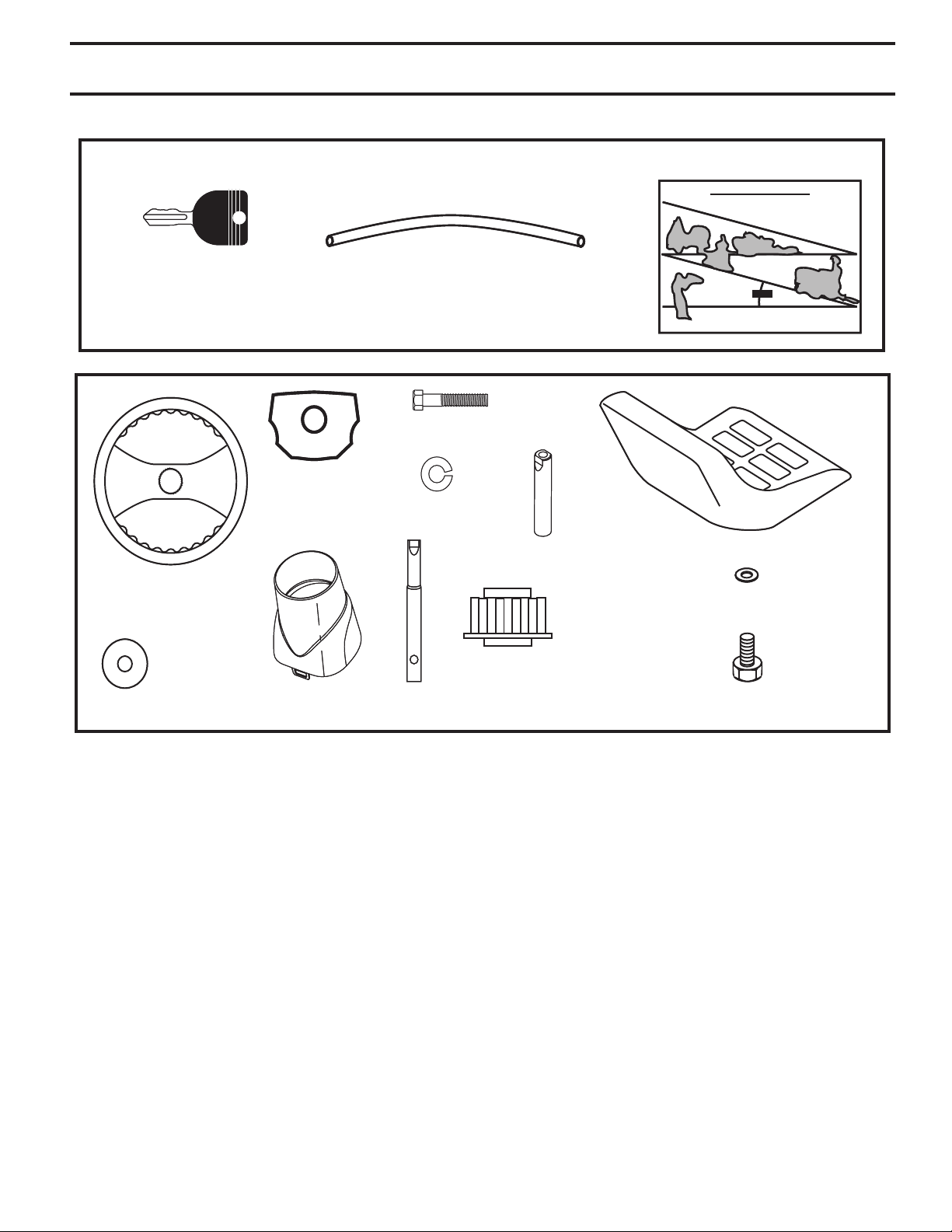
CONTENTS OF HARDWARE PACK
Slope Sheet
Key
Key
(2) Keys
(2) Keys
Insert
(1) Oil Drain Tube
(1) Oil Drain Tube
(1) Hex Bolt
Steering
Steering
Extension
Extension
Shaft
Shaft
Lock Washer
Slope Sheet
Steering
3TEERING
Wheel
7HEEL
Washer
Steering
Steering
Boot
Boot
Steering
Steering
Extension
Extension
Shaft
Shaft
Steering Wheel
Steering Wheel
Adapter
Adapter
SeatSeat
Washer
ª"OLT
5
Page 6
ASSEMBLY
Your new tractor has been assembled at the factory with exception of those parts left unassembled for shipping purposes.
To ensure safe and proper operation of your tractor all parts and hardware you assemble must be tightened securely. Use
the correct tools as necessary to insure proper tightness.
TOOLS REQUIRED FOR ASSEMBLY
A socket wrench set will make assembly easier. Stan dard
wrench sizes are listed.
(1) 1/2" wrench Utility knife
(2) 3/4" wrench Tire pres sure gauge
Pliers
When right or left hand is mentioned in this man ual, it means
when you are in the operating po si tion (seated be hind the
steer ing wheel).
TO REMOVE TRACTOR FROM
CAR TON
UNPACK CARTON
• Remove all accessible loose parts and parts cartons
from carton.
• Cut along dashed lines on all four panels of carton.
Remove end panels and lay side panels flat.
• Check for any additional loose parts or cartons and
remove.
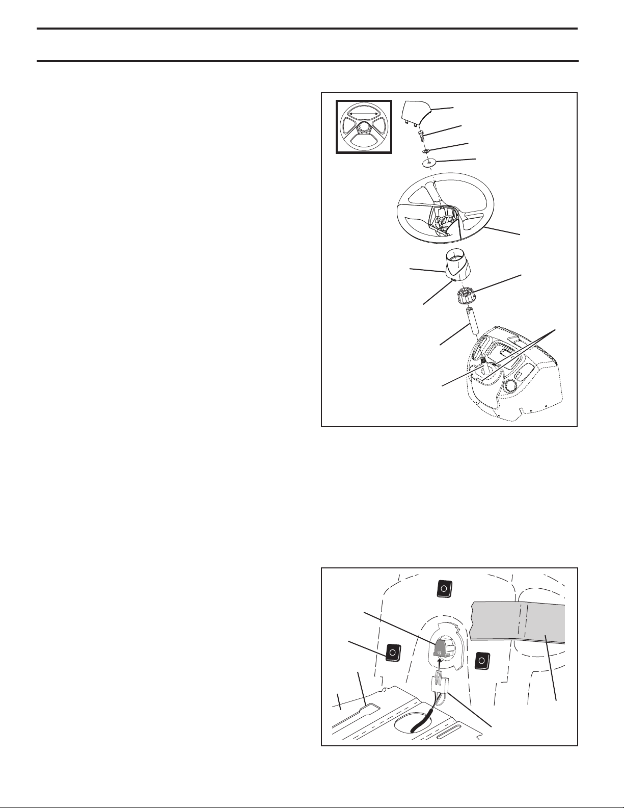
STEERING BOOT
TABS
EXTENSION SHAFT
INSERT
5/16 HEX BOLT
5/16 LOCK WASHER
LARGE FLAT WASHER
STEERING
WHEEL
ADAPTER
TAB
SLOTS
BEFORE REMOVING TRACTOR FROM
SKID
ATTACH STEERING WHEEL (See Fig. 1)
ASSEMBLE EXTENSION SHAFT AND BOOT
• Slide extension shaft onto lower steering shaft.
• Place tabs of steering boot over tab slots in dash and
push down to secure.
INSTALL STEERING WHEEL
• Position front wheels of the tractor so they are pointing
straight forward.
• Remove steering wheel adapter from steering wheel
and slide adapter onto steer ing shaft ex ten sion.
• Position steering wheel so cross bars are hor i zon tal
(left to right) and slide inside boot and onto adapt er.
• Assemble large flat washer, 5/16 lock washer, 5/16 hex
bolt and tighten se cure ly.
• Snap steering wheel insert into center of steer ing
wheel.
• Remove protective materials from trac tor hood and
grill.
IMPORTANT: CHECK FOR AND REMOVE ANY STAPLES IN
SKID THAT MAY PUNCTURE TIRES WHERE TRACTOR IS TO
ROLL OFF SKID.
LOWER STEERING SHAFT
03125
FIG. 1
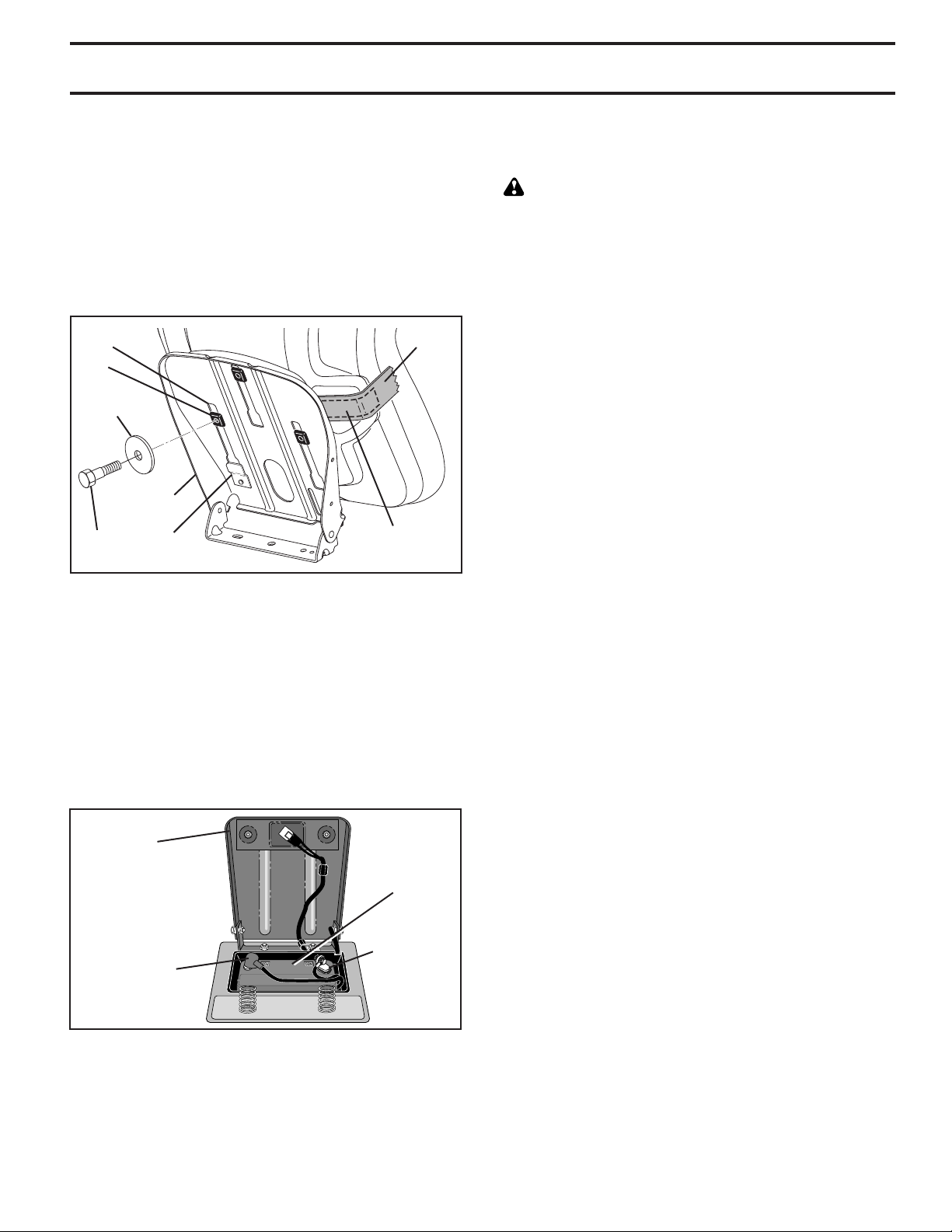
INSTALL SEAT (See Figs. 2 and 3)
• Remove bolt and flat washer se cur ing seat to cardboard
packing and set aside for as sem bly of seat to tractor.
Remove the cardboard packing and discard.
• Connect switch to seat.
• Place seat on seat pan so all three (3) bottom pads
are positioned over large slotted holes in pan.
SEAT
SWITCH
PAD
SLOT
SEAT
PAN
TAPE
WIRING HARNESS
Fig. 2
6
Page 7
ASSEMBLY
• Push down on seat to engage pads in slots and pull
seat towards rear of tractor.
• Raise seat and tighten bolt securely.
• Remove tape and discard.
• Lower seat into operating position and sit on seat.
Press clutch/brake pedal all the way down. If operating
position is not comfortable, adjust seat.
To adjust seat: Grasp adjustment handle and pull up, slide
seat to desired po si tion and release adjustment handle.
SLOT
PAD
FLAT
WASHER
SEAT PAN
BOLT
TAB
ADJUSTMENT
Fig. 3
TAPE
HANDLE
CHECK BATTERY (See Fig. 4)
• Lift seat pan to raised position.
• If this battery is put into service after month and year
indicated on label (label located between terminals)
charge battery for minimum of one hour at 6-10 amps.
(See "BATTERY" in MAINTENANCE section of this
manual for charging instructions).
SEAT PAN
LABEL
NOTE: You may now roll or drive your tractor off the skid.
Follow the ap pro pri ate instruction below to remove the
tractor from the skid.
WARNING: Before start ing, read, un der stand and fol low
all in struc tions in the Op er a tion section of this man u al. Be
sure tractor is in a well-ventilated area. Be sure the area in
front of tractor is clear of other peo ple and objects.
TO ROLL TRACTOR OFF SKID (See Op er a tion section for location and function of
con trols)
• Press lift lever plunger and raise at tach ment lift lever
to its highest po si tion.
• Release parking brake by depressing clutch/brake
ped al.
• Place gearshift lever in neutral (N) po si tion.
• Roll tractor forward off skid.
• Remove banding holding the de flec tor shield up against
tractor.
TO DRIVE TRACTOR OFF SKID (See Op er a tion section for location and func tion of
con trols)
• Be sure all the above assembly steps have been com-
plet ed.
• Check engine oil level and fill fuel tank with gasoline.
• Sit on seat in operating position, depress clutch/brake
pedal and set the parking brake.
• Place gear shift lever in neutral (N) position.
• Press lift lever plunger and raise at tach ment lift lever
to its highest position.
• Remove key from bag and start the engine (see "TO
START ENGINE" in the Operation section of this manual). After engine has started, move throttle control to
idle (slow) position.
• Depress clutch/brake pedal into full "BRAKE" position
and hold. Move gearshift lever to 1st gear.
• Slowly release clutch/brake pedal and slowly drive
tractor off skid.
• Apply brake to stop tractor, set parking brake and place
gearshift lever in neutral position.
• Turn ignition key to "STOP" position.
Continue with the instructions that follow.
TERMINAL
TERMINAL
FIG. 4
7
Page 8

ASSEMBLY
CHECK TIRE PRESSURE
The tires on your tractor were overinflated at the factory
for shipping purposes. Correct tire pressure is important
for best cutting performance.
• Reduce tire pressure to PSI shown on tires.
CHECK DECK LEVELNESS
For best cutting results, mower housing should be properly
leveled. See “TO LEVEL MOWER HOUSING” in the Service
and Adjustments section of this manual.
CHECK FOR PROPER POSITION OF ALL
BELTS
See the figures that are shown for replacing motion and
mower blade drive belts in the Service and Adjustments
sec tion of this manual. Verify that the belts are routed
correctly.
CHECK BRAKE SYSTEM
After you learn how to operate your tractor, check to see that
the brake is operating properly. See “TO CHECK BRAKE”
in the Service and Adjustments section of this manual.
✓CHECKLIST
BEFORE YOU OPERATE YOUR NEW TRAC TOR, WE
WISH TO ASSURE THAT YOU RECEIVE THE BEST PER FOR MANCE AND SAT IS FAC TION FROM THIS QUALITY
PROD UCT.
PLEASE REVIEW THE FOLLOWING CHECKLIST:
✓ All assembly instructions have been completed.
✓ No remaining loose parts in carton.
✓ Battery is properly prepared and charged.
✓ Seat is adjusted comfortably and tightened securely.
✓ All tires are properly inflated. (For shipping purposes,
the tires were overinflated at the factory).
✓ Be sure mower deck is properly leveled side-to-side/
front-to-rear for best cutting results. (Tires must be
properly inflated for leveling).
✓ Check mower and drive belts. Be sure they are routed
properly around pulleys and inside all belt keepers.
✓ Check wiring. See that all con nec tions are still secure
and wires are properly clamped.
WHILE LEARNING HOW TO USE YOUR TRACTOR, PAY
EXTRA ATTENTION TO THE FOLLOWING IMPORTANT
ITEMS:
✓ Engine oil is at proper level.
✓ Fuel tank is filled with fresh, clean, regular unleaded
gasoline.
✓ Become familiar with all controls, their location and
function. Operate them before you start the engine.
✓ Be sure brake system is in safe operating condition.
✓ Be sure Operator Presence System and Reverse Op-
eration System (ROS) are working properly (See the
Operation and Maintenance sections in this manual).
8
Page 9

OPERATION
These symbols may appear on your tractor or in literature supplied with the product. Learn and understand their meaning.
REVERSE
ENGINE OFF
OVER TEMP
LIGHT
ATTACHMENT
CLUTCH DISENGAGED
FREE WHEEL
(Automatic Models only)
NEUTRAL
REVERSE
OPERATION
SYSTEM (ROS)
FUEL
HIGH
ENGINE ON
OIL PRESSURE
ATTACHMENT
CLUTCH ENGAGED
LIGHTS ON
LOW
ENGINE START
BATTERY
DANGER, KEEP HANDS
AND FEET AWAY
CHOKE
PARKING BRAKE
REVERSE
DANGER indicates a hazard which, if not avoided,
will result in death or serious injury.
WARNING indicates a hazard which, if not avoided,
could result in death or serious injury.
CAUTION indicates a hazard which, if not avoided,
might result in minor or moderate injury.
FAST
P
FORWARD
KEEP AREA CLEAR
SLOW
PARKING BRAKE
LOCKED
MOWER HEIGHT
(SEE SAFETY RULES SECTION)
IGNITION SWITCH
PARKING BRAKE
UNLOCKED
MOWER LIFT
15
SLOPE HAZARDS
15
Failure to follow instructions
could result in serious injury or
death. The safety alert symbol
is used to identify safety information about hazards which can
result in death, serious injury
and/or property damage.
CAUTION when used without the alert symbol,
indicates a situation that could result in damage
to the tractor and/or engine.
HOT SURFACES indicates a hazard which,
if not avoided, could result in death, serious injury
and/or property damage.
FIRE indicates a hazard which, if not avoided,
could result in death, serious injury and/or
property damage.
9
Page 10
OPERATION
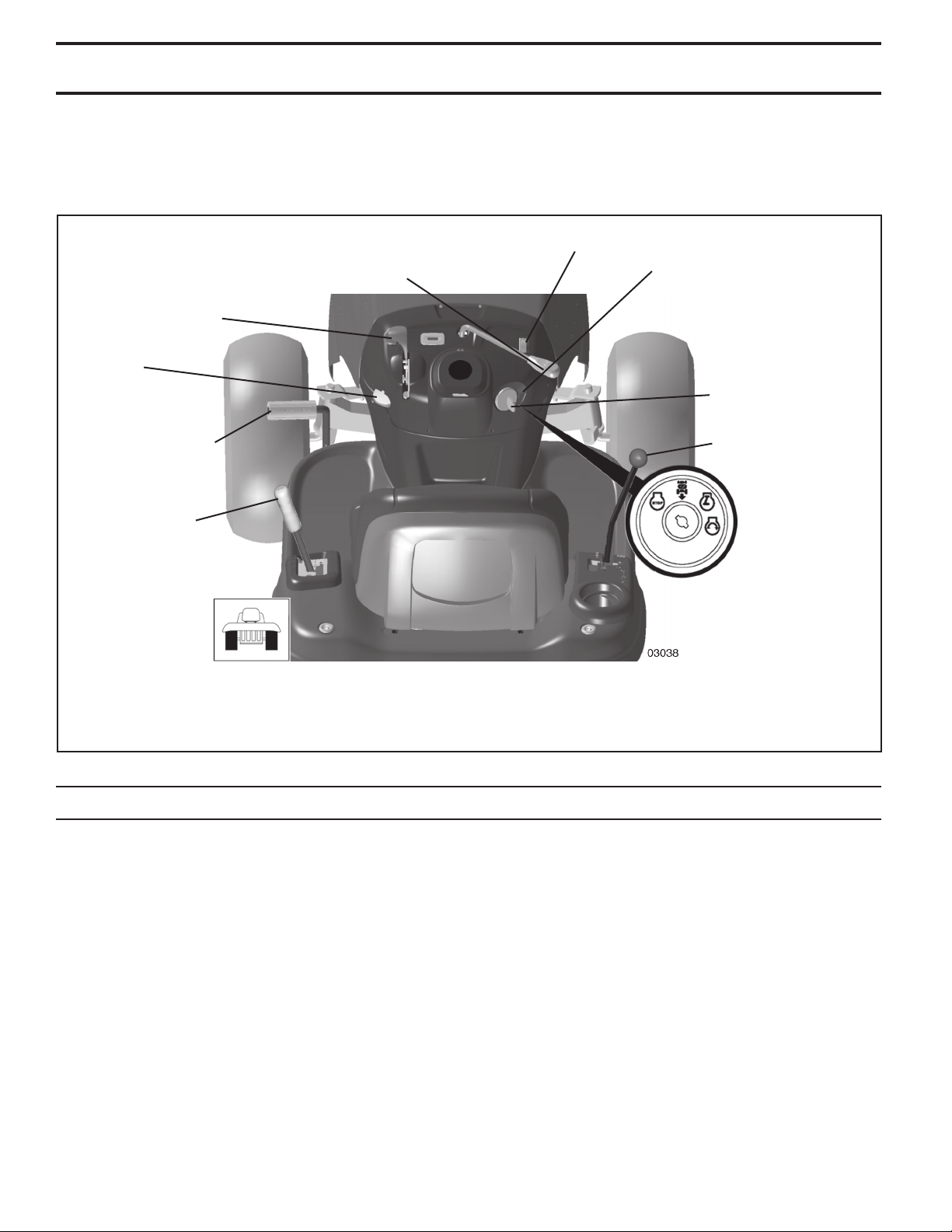
KNOW YOUR TRACTOR
READ THIS OWNER'S MANUAL AND SAFETY RULES BEFORE OPERATING YOUR TRACTOR
Compare the illustrations with your tractor to familiarize yourself with the locations of various controls and ad just ments.
Save this manual for future reference.
LIGHT SWITCH
ATTACHMENT
CLUTCH LEVER
THROTTLE/CHOKE
CONTROL
PARKING
BRAKE
ROS "ON"
POSITION
IGNITION
SWITCH
CLUTCH/BRAKE
PEDAL
ATTACHMENT
LIFT LEVER
Our tractors conform to the applicable safety standards of the American National Standards Institute.
ATTACHMENT CLUTCH LEVER - Used to engage the
mower blades, or other attachments mounted to your
tractor.
ATTACHMENT LIFT LEVER - Used to raise, lower, and
adjust the mower deck or other attachments mounted to
your tractor.
CLUTCH/BRAKE PEDAL - Used for declutching and brak ing the tractor and starting the engine.
GEARSHIFT LEVER - Selects the speed and di rec tion
of the tractor.
GEAR SHIFT
LEVER
FIG. 5
IGNITION SWITCH - Used for starting and stopping the
engine.
LIGHT SWITCH - Turns the headlights on and off.
PARKING BRAKE - Locks clutch/brake pedal into the
brake position.
REVERSE OPERATION SYSTEM (ROS) “ON” POSITION - Allows operation of mower deck or other powered
attachment while in reverse.
THROTTLE/CHOKE CONTROL - Used for starting and
con trol ling engine speed.
10
Page 11
OPERATION
The operation of any tractor can result in foreign objects thrown into the eyes, which can result
in severe eye dam age. Always wear safety glass es or eye shields while operating your tractor or
per form ing any adjustments or repairs. We rec om mend a wide vision safety mask over spectacles
or stan dard safety glasses.
HOW TO USE YOUR TRACTOR
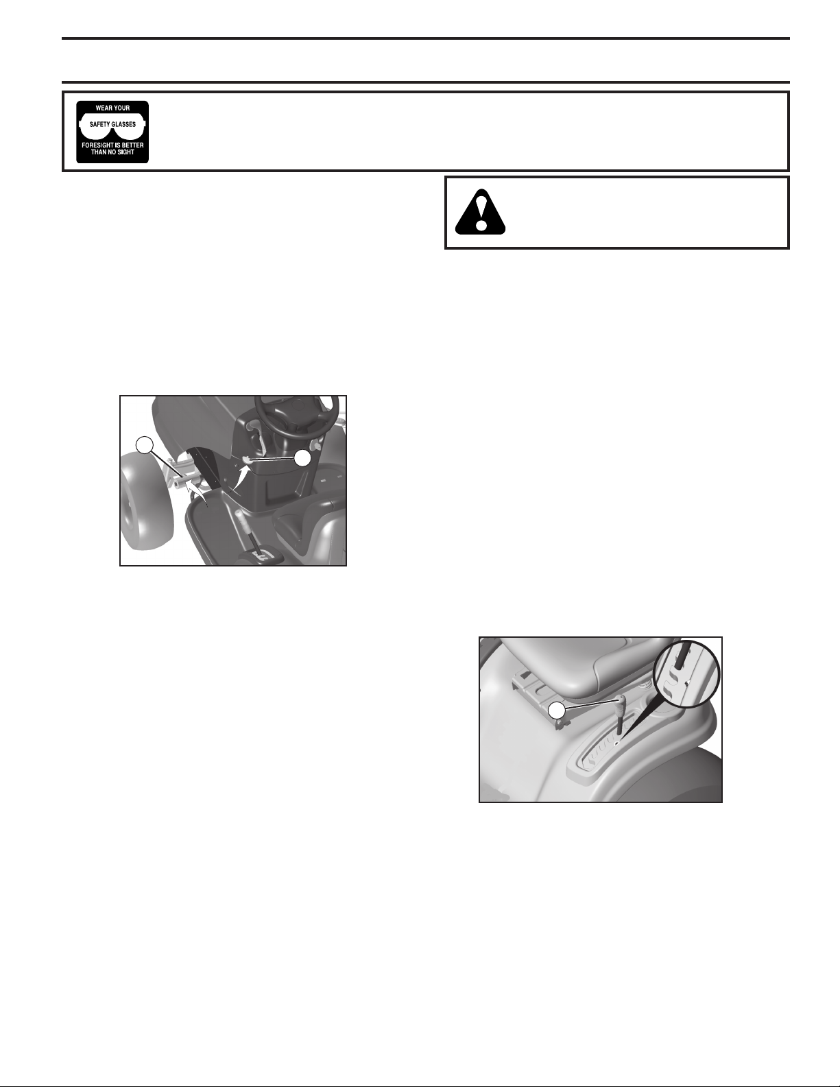
TO SET PARKING BRAKE (See Fig. 6)
Your tractor is equipped with an operator presence sens ing switch. When engine is running, any attempt by the
op er a tor to leave the seat without first setting the parking
brake will shut off the engine.
• Depress clutch/brake pedal into full “BRAKE” position
and hold.
• Place parking brake lever in “ENGAGED” position
and re lease pressure from clutch/brake pedal. Pedal
should re main in “BRAKE” position. Make sure parking
brake will hold tractor secure.
B
C
FIG. 6
STOPPING (See Fig. 6)
MOWER BLADES -
• To stop mower blades,move attachment clutch lever
to “DIS EN GAGED” po si tion.
GROUND DRIVE -
• To stop ground drive, depress clutch/brake pedal into
full “BRAKE” po si tion.
• Move gearshift lever to neutral (N) po si tion.
ENGINE -
• Move throttle control between half and full speed (fast)
position.
NOTE: Failure to move throttle control between half and
full speed (fast) position, before stop ping may cause engine
to “back fire”.
• Turn ignition key to “OFF” position and remove key.
Always remove key when leaving tractor to prevent
un au tho rized use.
• Never use choke to stop engine.
IMPORTANT: LEAVING THE IGNITION SWITCH IN ANY
POSITION OTHER THAN "OFF" WILL CAUSE THE BATTERY
TO BE DIS CHARGED, (DEAD).
NOTE: Under certain conditions when tractor is standing
idle with the engine running, hot engine exhaust gases may
cause “brown ing” of grass. To eliminate this possibility, always stop engine when stopping tractor on grass areas.
CAUTION: Always stop tractor com plete ly, as described above, before leav ing the operator's position; to empty
grass catch er, etc.
TO USE THROTTLE CONTROL (See Fig. 6)
Always operate engine at full speed (fast).
• Operating engine at less than full speed (fast) reduces
the engine's operating efficiency.
• Full speed (fast) of fers the best mower per for mance.
TO MOVE FORWARD AND BACKWARD
(See Fig. 6)
The direction and speed of movement is controlled by the
gearshift lever.
• Start tractor with clutch/brake pedal depressed and
gearshift lever in neutral (N) position.
• Move gearshift lever to desired position.
• Slowly release clutch/brake pedal to start movement.
IMPORTANT: BRING TRACTOR TO A COMPLETE STOP
BEFORE SHIFTING OR CHANGING GEARS. FAILURE
TO DO SO WILL SHORTEN THE USEFUL LIFE OF YOUR
TRANSAXLE.
TO ADJUST MOWER CUT TING HEIGHT
(See Fig. 7)
The po si tion of the at tach ment lift le ver (A) de ter mines the
cut ting height.
A
FIG. 7
• Put attachment lift lever in desired cutting height
slot.
The cutting height range is ap prox i mate ly 1" to 4". The
heights are measured from the ground to the blade tip with
the engine not running. These heights are approximate
and may vary depending upon soil conditions, height of
grass and types of grass being mowed.
• The average lawn should be cut to approximately 2-1/2
inches during the cool season and to over 3 inches
during hot months. For healthier and better looking
lawns, mow often and after moderate growth.
• For best cutting performance, grass over 6 inches
11
in height should be mowed twice. Make the first cut
relatively high; the second to de sired height.
Page 12
OPERATION
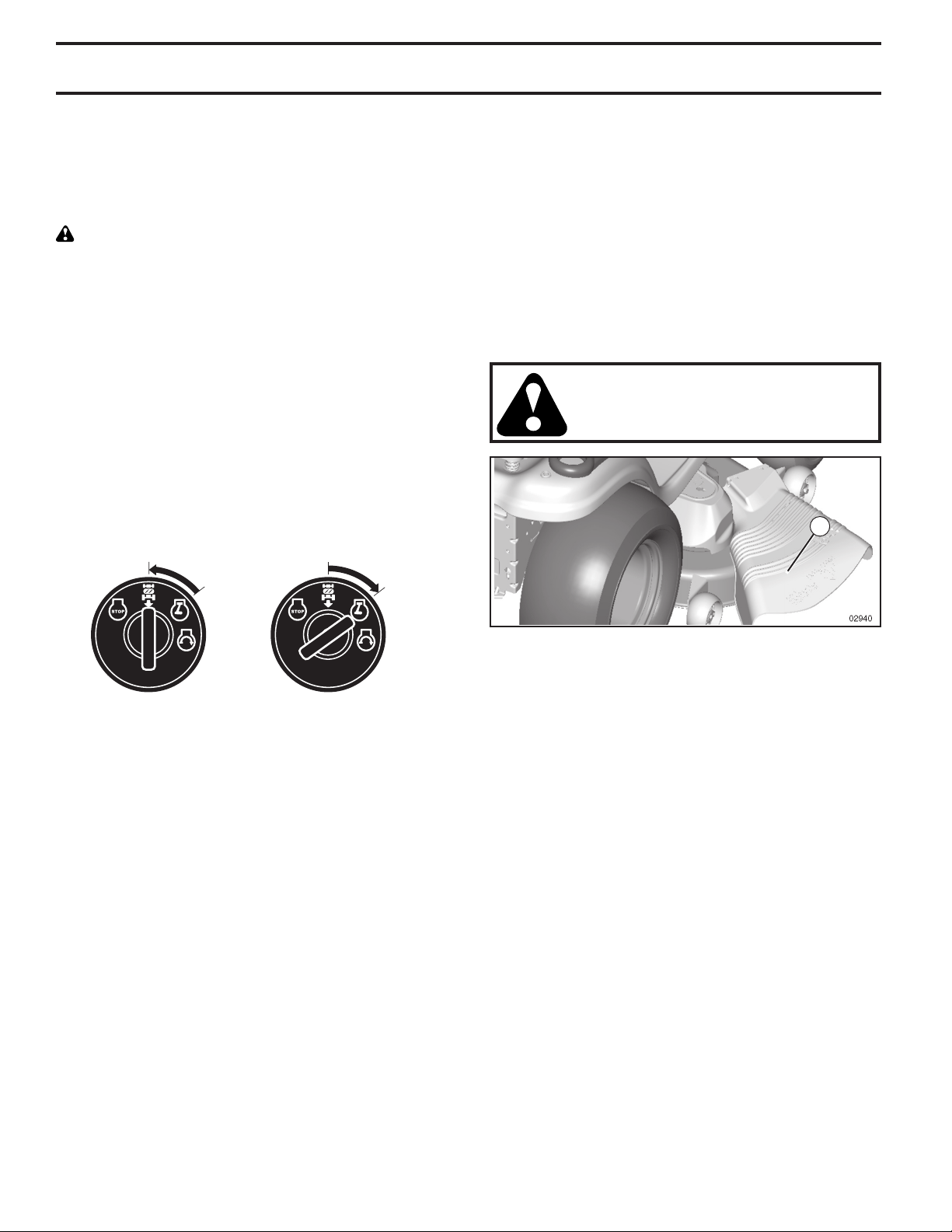
REVERSE OPERATION SYSTEM (ROS)
Your tractor is equipped with a Reverse Operation System
(ROS). Any attempt by the operator to travel in the reverse
direction with the attachment clutch engaged will shut off
the engine unless ignition key is placed in the ROS "ON"
position.
WARNING: Backing up with the attachment clutch engaged while mowing is strongly discouraged. Turning the
ROS "ON", to allow reverse operation with the attachment
clutch engaged, should only be done when the operator
decides it is necessary to reposition the machine with the
attachment engaged. Do not mow in reverse unless
absolutely necessary.
USING THE REVERSE OPERATION SYSTEM -
• Depress clutch/brake pedal all the way down and
hold.
• With engine running, turn ignition key counterclockwise
to ROS "ON" position.
• Look down and behind before backing.
• Move gear shift lever to reverse (R) po si tion and slowly
release clutch/brake pedal to start movement.
• When use of the ROS is no longer needed, turn the
ignition key clockwise to engine "ON" position.
ROS "ON" POSITION
ENGINE "ON" POSITION
(NORMAL OPERATING)
TO OPERATE MOWER (See Fig. 8)
Your tractor is equipped with an operator presence sensing
switch. Any attempt by the operator to leave the seat with
the engine running and the attachment clutch engaged will
shut off the engine. You must remain fully and centrally
positioned in the seat to prevent the engine from hesitating or cutting off when operating your equipment on rough,
rolling terrain or hills.
• Select desired height of cut with attachment lift lever.
• Start mower blades by engaging at tach ment clutch
control.
TO STOP MOWER BLADES disengage at tach ment clutch con trol.
CAUTION: Do not operate the mower
without either the en tire grass catcher,
on mowers so equipped, or the deflector
shield (S) in place.
S
FIG. 8
8
2
8
2
0
12
Page 13

OPERATION
TO OPERATE ON HILLS
WARNING: Do not drive up or down
hills with slopes great er than 15° and
do not drive across any slope.
• Choose the slowest speed before starting up or down
hills.
• Avoid stopping or changing speed on hills.
• If stopping is absolutely necessary, push clutch/brake
pedal quickly to brake position and engage parking
brake.
• Move gearshift lever to 1st gear. Be sure you have
allowed room for tractor to roll slightly as you restart
movement.
• To restart movement, slowly release parking brake and
clutch/brake pedal.
• Make all turns slowly.
TO TRANSPORT
• Raise attachment lift to highest position with at tach ment
lift control.
• When pushing or towing your tractor, be sure gearshift
lever is in neutral (N) position.
• Do not push or tow tractor at more than five (5) MPH.
NOTE: To protect hood from damage when transporting
your tractor on a truck or a trailer, be sure hood is closed
and secured to tractor. Use an appropriate means of tying
hood to tractor (rope, cord, etc.).
ADD GASOLINE
• Fill fuel tank to bottom of filler neck. Do not overfill.
Use fresh, clean, regular un lead ed gasoline with a
minimum of 87 octane. (Use of leaded gasoline will
increase carbon and lead oxide deposits and reduce
valve life). Do not mix oil with gasoline. Purchase fuel
in quan ti ties that can be used within 30 days to assure
fuel freshness.
CAUTION: Wipe off any spilled oil or
fuel. Do not store, spill or use gasoline
near an open flame.
IMPORTANT: WHEN OPERATING IN TEMPERATURES
BELOW32°F(0°C), USE FRESH, CLEAN WINTER GRADE
GAS O LINE TO HELP INSURE GOOD COLD WEATHER
START ING.
CAUTION: Alcohol blended fuels (called
gas o hol or using ethanol or methanol) can attract moisture which leads to sep a ra tion and
for ma tion of acids during storage. Acidic gas
can damage the fuel system of an engine while
in storage. To avoid engine problems, the fuel
system should be emptied before stor age of
30 days or longer. Drain the gas tank, start
the engine and let it run until the fuel lines
and carburetor are empty. Use fresh fuel next
sea son. See Storage In struc tions for additional
information. Never use engine or carburetor
cleaner products in the fuel tank or permanent
damage may occur.
TOWING CARTS AND OTHER AT TACH MENTS
Tow only the attachments that are recommended by and
comply with specifications of the manufacturer of your tractor. Use common sense when towing. Too heavy of a load,
while on a slope, is dangerous. Tires can lose traction with
the ground and cause you to lose control of your tractor.
BEFORE STARTING THE ENGINE
CHECK ENGINE OIL LEVEL
The engine in your tractor has been shipped, from the
factory, already filled with sum mer weight oil.
• Check engine oil with tractor on level ground.
• Remove oil fill cap/dipstick and wipe clean, reinsert the
dipstick and screw cap tight, wait for a few seconds,
remove and read oil level. If necessary, add oil until
“FULL” mark on dipstick is reached. Do not overfill.
• For cold weather operation you should change oil for
easier starting (See “OIL VISCOSITY CHART” in the
Maintenance sec tion of this manual).
• To change engine oil, see the Maintenance section in
this manual.
TO START ENGINE (See Fig. 7)
When starting the engine for the first time or if the engine
has run out of fuel, it will take extra cranking time to move
fuel from the tank to the engine.
• Sit on seat in operating position, depress clutch/brake
pedal and set parking brake.
• Place gear shift lever in neutral (N) position.
• Move attachment clutch to “DISENGAGED” position.
• Move throttle control to choke ( ) position.
NOTE: Before starting, read the warm and cold starting
pro ce dures below.
• Insert key into ignition and turn key clockwise to “START”
position and release key as soon as engine starts.
Do not run starter continuously for more than fifteen
sec onds per minute. If the engine does not start after
several attempts, move throttle control to fast position,
wait a few minutes and try again. If engine still does
not start, move the throttle control back to the choke (
) position and retry.
WARM WEATHER STARTING (50° F and above)
• When engine starts, move the throttle control to the
fast position.
• The attachments and ground drive can now be used. If
the engine does not accept the load, restart the engine
and allow it to warm up for one minute using the choke
as described above.
13
Page 14

OPERATION
COLD WEATHER STARTING ( 50° F and below)
• When engine starts, allow engine to run with the throttle
control in the choke (
roughly, then move throttle control to fast position. This
may require an engine warm-up period from several
seconds to several minutes, depending on the tem per a ture.
• The attachments can also be used during the engine
warm-up period.
NOTE: If at a high altitude (above 3000 feet) or in cold
tem per a tures (below 32 F) the carburetor fuel mixture may
need to be adjusted for best engine performance. See “TO
ADJUST CAR BU RE TOR” in the Service and Adjustments
section of this manual.
MOWING TIPS
• Mower should be properly leveled for best mowing per for mance. See "TO LEVEL MOWER HOUSING" in the
Service and Adjustments section of this manual.
• The left hand side of mower should be used for trim ming.
• Drive so that clippings are discharged onto the area
that has been cut. Have the cut area to the right of the
machine. This will result in a more even distribution of
clippings and more uniform cutting.
• When mowing large areas, start by turning to the right
so that clippings will discharge away from shrubs,
fences, drive ways, etc. After one or two rounds, mow
in the opposite direction making left hand turns until
finished (See Fig. 9).
) position until the engine runs
FIG. 9
• If grass is extremely tall, it should be mowed twice to
reduce load and possible fire hazard from dried clip pings. Make first cut relatively high; the second to the
desired height.
• Do not mow grass when it is wet. Wet grass will plug
mower and leave undesirable clumps. Allow grass to
dry before mowing.
• Always operate engine at full throttle when mow-
ing to assure better mowing performance and proper
dis charge of ma te ri al. Regulate ground speed by se lect ing a low enough gear to give the mower cutting
per for mance as well as the quality of cut desired.
• When operating attachments, select a ground speed
that will suit the terrain and give best performance of
the attachment being used.
14
Page 15
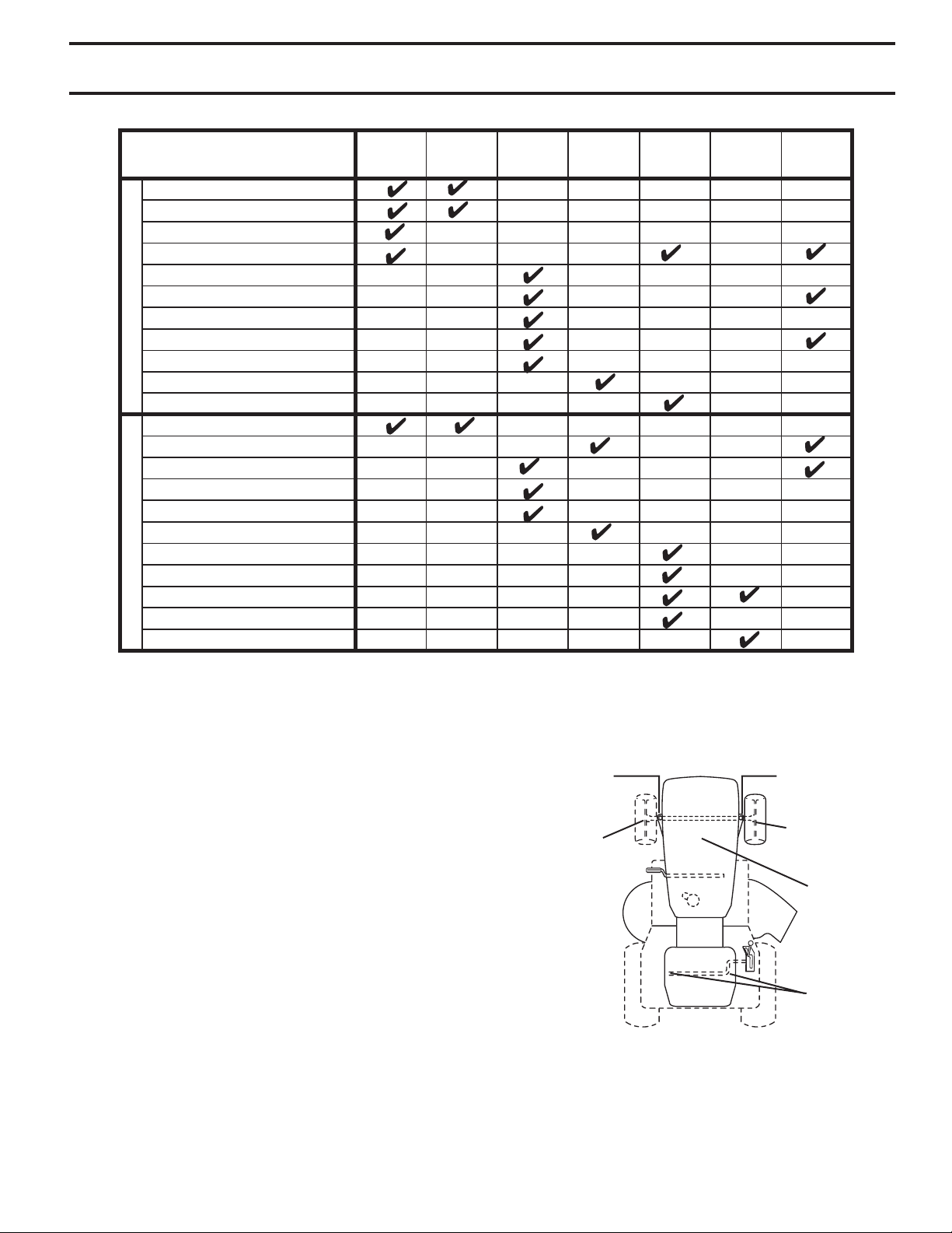
MAINTENANCE
MAINTENANCE
SCHEDULE
Check Brake Operation
Check Tire Pressure
T
Check Operator Presence & ROS Systems
R
Check for Loose Fasteners
A
Check/Replace Mower Blades
C
T
Lubrication Chart
0
Check Battery Level
R
Clean Battery and Terminals
Check Transaxle Cooling
Check Mower Levelness
Check V-Belts
Check Engine Oil Level
Change Engine Oil (with oil filter)
Change Engine Oil (without oil filter)
E
Clean Air Filter
N
Clean Air Screen
G
Inspect Muffler/Spark Arrester
I
Replace Oil Filter (If equipped)
N
E
Clean Engine Cooling Fins
Replace Spark Plug
Replace Air Filter Paper Cartridge
Replace Fuel Filter
1 - Change more often when operating under a heavy load or
in high ambient temperatures.
2 - Service more often when operating in dirty or dusty conditions.
BEFORE
EACH
USE
EVERY
8
HOURS
EVERY
25
HOURS
3 - Replace blades more often when mowing in sandy soil.
4 - Not required if equipped with maintenance-free battery.
4
1,2
EVERY
50
HOURS
3
2
2
1,2
EVERY
100
HOURS
1
EVERY
SEASON
,
2
2
2
BEFORE
STORAGE
maint_sch-tractore.ROS.e
GENERAL RECOMMENDATIONS
The warranty on this tractor does not cover items that
have been subjected to operator abuse or negligence. To
receive full value from the warranty, operator must main tain
tractor as instructed in this manual.
Some adjustments will need to be made periodically to
properly maintain your tractor.
At least once a season, check to see if you should
make any of the adjustments described in the Service
and Adjustments section of this manual.
• At least once a year you should replace the spark
plug, clean or replace air filter, and check blades and
belts for wear. A new spark plug and clean air filter
assure proper air-fuel mixture and help your engine
run better and last longer.
BEFORE EACH USE
• Check engine oil level.
• Check brake operation.
• Check tire pressure.
• Check operator presence and
ROS systems for proper operation.
• Check for loose fasteners.
LUBRICATION CHART
dSPINDLE ZERK
dFRONT WHEEL
BEARING ZERK
cSAE 30 OR 10W30 MOTOR OIL
dGENERAL PURPOSE GREASE
eREFER TO MAINTENANCE “ENGINE” SECTION
IMPORTANT: DO NOT OIL OR GREASE THE PIVOT POINTS WHICH
HAVE SPECIAL NYLON BEARINGS. VISCOUS LU BRI CANTS WILL
ATTRACT DUST AND DIRT THAT WILL SHORT EN THE LIFE OF
THE SELF-LU BRI CAT ING BEARINGS. IF YOU FEEL THEY MUST
BE LU BRI CAT ED, USE ONLY A DRY, POW DERED GRAPHITE TYPE
LU BRI CANT SPARINGLY.
15
dSPINDLE ZERK
dFRONT WHEEL
BEARING ZERK
eENGINE
cGEARSHIFT
PIVOTS
Page 16
MAINTENANCE
TRACTOR
Always observe safety rules when per form ing any main te nance.
BRAKE OPERATION
If tractor requires more than five (5) feet to stop at highest
speed in high est gear on a level, dry concrete or paved
surface, then brake must be checked and ad just ed. (See
“TO ADJUST BRAKE” in the Ser vice and Ad just ments
section of this manual).
TIRES
• Maintain proper air pressure in all tires (See “PROD UCT
SPEC I FI CA TIONS” section of this man ual).
• Keep tires free of gasoline, oil, or insect control chemi cals which can harm rubber.
• Avoid stumps, stones, deep ruts, sharp objects and
other hazards that may cause tire damage.
NOTE: To seal tire punctures and pre vent flat tires due to
slow leaks, tire sealant may be purchased from your local
parts dealer. Tire sealant also pre vents tire dry rot and
corrosion.
OPERATOR PRESENCE SYS TEM AND REVERSE OPERATION SYSTEM (ROS)
Be sure operator presence and reverse operation sys tems
are work ing properly. If your tractor does not function as
described, repair the problem immediately.
• The engine should not start unless the brake pedal is
fully de pressed, and the attachment clutch con trol is
in the dis en gaged position.
CHECK OPERATOR PRESENCE SYSTEM
• When the engine is running, any attempt by the op er a tor
to leave the seat without first setting the parking brake
should shut off the engine.
• When the engine is running and the at tach ment clutch
is engaged, any attempt by the operator to leave the
seat should shut off the engine.
• The attachment clutch should never operate unless
the operator is in the seat.
CHECK REVERSE OPERATION (ROS) SYSTEM
• When the engine is running with the ignition switch in
the engine "ON" position and the at tach ment clutch
engaged, any attempt by the operator to shift into
reverse should shut off the engine.
• When the engine is running with the ignition switch in
the ROS "ON" position and the at tach ment clutch engaged, any attempt by the operator to shift into reverse
should NOT shut off the engine.
ROS "ON" POSITION
ENGINE "ON" POSITION
(NORMAL OPERATING)
BLADE CARE
For best results mower blades must be kept sharp. Re place
bent or damaged blades.
CAUTION: Use only a replacement blade
approved by the manufacturer of your
tractor. Using a blade not approved
by the manufacturer of your tractor is
hazardous, could damage your tractor
and void your warranty.
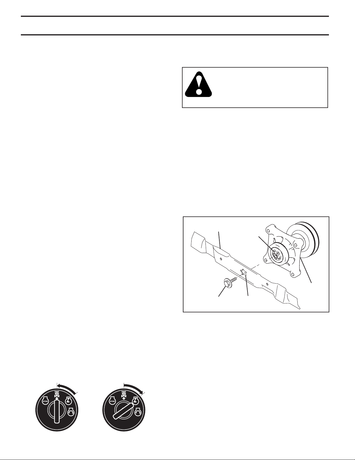
BLADE REMOVAL (See Fig. 10)
• Raise mower to highest position to allow access to
blades.
NOTE: Protect your hands with gloves and/or wrap blade
with heavy cloth.
• Remove blade bolt by turning coun ter clock wise.
• Install new blade with stamped "THIS SIDE UP" facing
deck and mandrel assembly.
IMPORTANT: To ensure proper as sem bly, center hole in
blade must align with star on mandrel assembly.
• Install and tighten blade bolt securely (45-55 Ft. Lbs.
torque).
IMPORTANT: Special blade bolt is heat treated.
BLADE
BLADE BOLT
(SPECIAL)
STAR
CENTER
HOLE
02
545
MANDREL
ASSEMBLY
FIG. 10
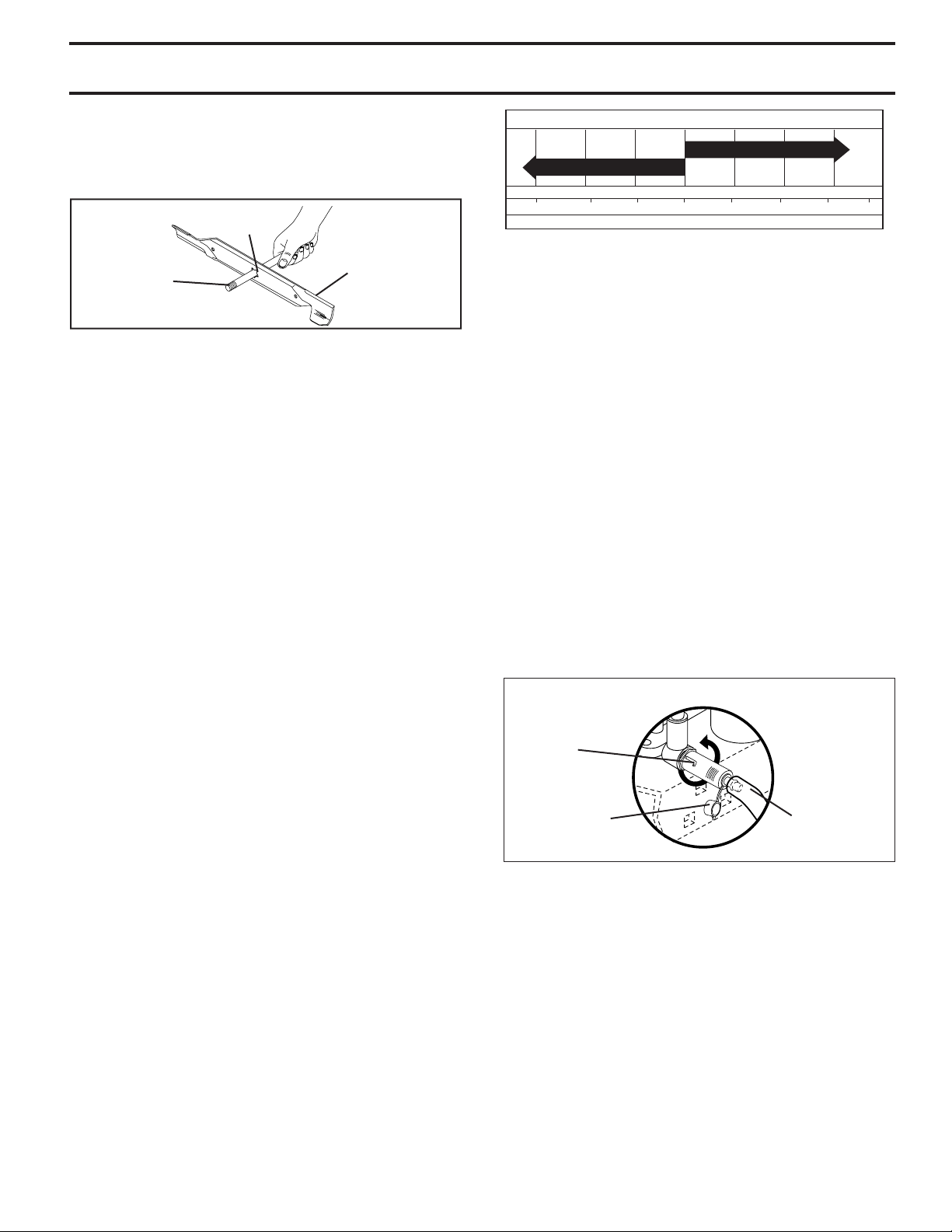
TO SHARPEN BLADE (See Fig. 11)
NOTE: We do not recommend sharpening blade - but if
you do, be sure the blade is balanced.
Care should be taken to keep the blade balanced. An un bal anced blade will cause excessive vibration and even tual
dam age to mower and engine.
• The blade can be sharpened with a file or on a grinding wheel. Do not attempt to sharpen while on the
mower.
• To check blade balance, you will need a 5/8" diameter
steel bolt, pin, or a cone balancer. (When using a
cone balancer, follow the instructions supplied with
bal anc er.)
NOTE: Do not use a nail for balancing blade. The lobes of
the center hole may appear to be centered, but are not.
16
Page 17
MAINTENANCE
• Slide blade on to an unthreaded portion of the steel bolt
or pin and hold the bolt or pin parallel with the ground.
If blade is balanced, it should remain in a horizontal
position. If either end of the blade moves downward,
sharpen the heavy end until the blade is balanced.
CENTER HOLE
5/8" BOLT
OR PIN
BLADE
FIG. 11
BATTERY
Your tractor has a battery charging system which is suf fi cient
for normal use. However, periodic charging of the battery
with an automotive charger will extend its life.
• Keep battery and terminals clean.
• Keep battery bolts tight.
• Keep small vent holes open.
• Recharge at 6-10 amperes for 1 hour.
NOTE: The original equipment battery on your tractor is
maintenance free. Do not attempt to open or remove caps
or covers. Adding or checking level of electrolyte is not
nec es sary.
TO CLEAN BATTERY AND TERMINALS
Corrosion and dirt on the battery and terminals can cause
the battery to “leak” power.
• Disconnect BLACK battery cable first then RED bat tery cable and remove battery from tractor.
• Rinse the battery with plain water and dry.
• Clean terminals and battery cable ends with wire brush
until bright.
• Coat terminals with grease or petroleum jelly.
• Reinstall battery (See “REPLACING BATTERY” in the
Service and Adjustment sec tion of this manual).
V-BELTS
Check V-belts for deterioration and wear after 100 hours and
replace if necessary. The belts are not adjustable. Re place
belts if they begin to slip from wear.
TRANSAXLE COOLING
Keep transaxle free from build-up of dirt and chaff which
can restrict cooling.
ENGINE
LUBRICATION
Only use high quality detergent oil rated with API service
classification SG-SL. Select the oil’s SAE viscosity grade
according to your expected operating temperature.
SAE VISCOSITY GRADES
SAE 30
5W-30
-20 0 30 40
F
C
-30
TEMPERATURE RANGE ANTICIPATED BEFORE NEXT OIL CHANGE
-20 0
-10
32
60
10
80
20 30 40
oil_visc_chart1_e
FIG. 12
NOTE: Although multi-viscosity oils (5W30, 10W30 etc.)
improve starting in cold weather, they will result in increased
oil consumption when used above 32°F. Check your engine
oil level more frequently to avoid possible engine damage
from running low on oil.
Change the oil after every 50 hours of operation or at least
once a year if the tractor is not used for 50 hours in one
year.
Check the crankcase oil level before starting the engine
and after each eight (8) hours of operation. Tighten oil fill
cap/dipstick securely each time you check the oil level.
TO CHANGE ENGINE OIL (See Figs. 12 and 13)
Determine temperature range expected before oil change.
All oil must meet API service classification SG-SL.
• Be sure tractor is on level surface.
• Oil will drain more freely when warm.
• Catch oil in a suitable container.
• Remove oil fill cap/dipstick. Be careful not to allow dirt
to enter the engine when changing oil.
• Remove yellow cap from end of drain valve and install
the drain tube onto the fitting.
OIL DRAIN VALVE
CLOSED
AND
LOCKED
POSITION
YEL LOW CAP
DRAIN
TUBE
FIG. 13
• Unlock drain valve by pushing inward and turning
coun ter clock wise.
• To open, pull out on the drain valve.
• After oil has drained completely, close and lock the
drain valve by pushing inward and turning clockwise
until the pin is in the locked position as shown.
• Remove the drain tube and replace the cap onto to the
bottom fitting of the drain valve.
• Refill engine with oil through oil fill dipstick tube. Pour
slowly. Do not overfill. For approximate capacity see
“PRODUCT SPECIFICATIONS” section of this man u al.
• Use gauge on oil fill cap/dipstick for checking level.
Be sure dipstick cap is tightened securely for accurate
reading. Keep oil at “FULL” line on dipstick. Tighten cap
onto the tube securely when finished.
17
100
Page 18

MAINTENANCE
CLEAN AIR SCREEN
Air screen must be kept free of dirt and chaff to prevent
engine dam age from overheating. Clean with a wire brush
or com pressed air to re move dirt and stubborn dried gum
fibers.
AIR FILTER
Your engine will not run properly using a dirty air filter.
Service air cleaner more often under dusty conditions. See
Engine Manual.
ENGINE OIL FILTER
Replace the engine oil filter every season or every other
oil change if the tractor is used more than 100 hours in
one year.
MUFFLER
Inspect and replace corroded muffler and spark arrester
(if equipped) as it could create a fire hazard and/or damage.
SPARK PLUGS
Replace spark plugs at the beginning of each mowing season or after every 100 hours of use, whichever comes first.
Spark plug type and gap setting is shown in "PROD UCT
SPECIFICATIONS" section of this manual.
IN-LINE FUEL FILTER (See Fig. 14)
The fuel filter should be replaced once each season. If fuel
filter becomes clogged, ob struct ing fuel flow to car bu re tor,
re place ment is re quired.
• With engine cool, remove filter and plug fuel line sec tions.
• Place new fuel filter in position in fuel line with arrow
pointing towards carburetor.
• Be sure there are no fuel line leaks and clamps are
properly positioned.
• Immediately wipe up any spilled gasoline.
CLAMP
FIG. 14
CLAMP
FUEL
FILTER
CLEANING
• Clean engine, battery, seat, finish, etc. of all foreign
matter.
• Keep finished surfaces and wheels free of all gasoline,
oil, etc.
• Protect painted surfaces with automotive type wax.
We do not recommend using a garden hose or pressure
washer to clean your tractor unless the engine and transmission are covered to keep water out. Water in engine or
transmission will shorten the useful life of your tractor. Use
compressed air or a leaf blower to remove grass, leaves
and trash from tractor and mower.
18
Page 19

SERVICE AND ADJUSTMENTS
WARNING: TO AVOID SE RI OUS IN JU RY, BEFORE PERFORMING ANY SERVICE OR ADJUSTMENTS:
• Depress clutch/brake pedal fully and set parking brake.
• Place gearshift lever in neutral (N) position.
• Place attachment clutch in “DISENGAGED” position.
• Turn ignition key to “STOP” and remove key.
• Make sure the blades and all moving parts have completely stopped.
• Disconnect spark plug wire from spark plug and place wire where it cannot come in contact
with plug.
TRACTOR
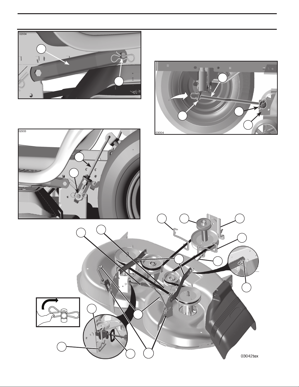
TO REMOVE MOWER (See Fig. 15)
• Place attachment clutch in “DIS EN GAGED” position.
• Lower attachment lift lever to its lowest position.
• Roll belt off engine pulley (M) and belt keepers (G).
• Remove retainer spring (K), slide col lar (L) off and push
housing guide (P) out of brack et.
• Remove clutch cable spring (Q) from idler arm (R).
• Disconnect front link (E) from mower - remove retainer
spring and washer.
• Go to either side of mower and disconnect mower
suspension arm (A) from chassis pin (B) and rear lift
link (C) from rear mower bracket (D) - remove retainer
springs and washers.
CAUTION: AFTER REAR LIFT LINKS
ARE DISCONNECTED, THE ATTACHMENT LIFT LEVER WILL BE SPRING
LOADED. HAVE A TIGHT GRIP ON LIFT
LEVER WHEN CHANGING POSITION
OF THE LEVER.
• Slide mower out from under right side of tractor.
IMPORTANT: IF AN ATTACHMENT OTHER THAN THE
MOWER IS TO BE MOUNTED ON THE TRAC TOR,
REMOVE THE FRONT LINK (E) AND REAR LIFT LIKS
(C) FROM TRACTOR AND HOOK THE CLUTCH SPRING
(Q) INTO THE CABLE GUIDE ON FRONT EDGE OF
LOWER DASH.
TO INSTALL MOWER (See Fig. 16–19)
Be sure tractor is on level surface and engage park ing
brake.
• Lower attachment lift lever to it's lowest position.
CAUTION: LIFT LEVER IS SPRING
LOADED. HAVE A TIGHT GRIP ON
LIFT LEVER, LOWER IT SLOWLY AND
ENGAGE IN LOWEST POSITION.
NOTE: Be sure mower side suspension arms (A) are point-
ing forward before sliding mower under tractor.
• Slide mower under tractor until it is centered under
tractor.
• ATTACH MOWER SIDE SUSPENSION ARMS (A) TO
CHASSIS - Position hole in arm over pin (B) on outside
of tractor chassis and secure with retainer spring.
• Repeat on opposite side of tractor.
G
M
F
K
Q
P
R
L
C
D
19
A
FIG. 15
G
E
B
Page 20
A
SERVICE AND ADJUSTMENTS
• ATTACH FRONT LINK (E) - Work from left side of tractor. Insert rod end of link assembly through front hole
in tractor front suspension bracket (F).
• Insert end of link (E) into hole in front mower bracket
and secure with washer and retainer spring (J).
B
FIG. 16
• ATTACH REAR LIFT LINKS (C) - Lift rear corner of
mower and position slot in link assembly over pin (D)
on rear mower bracket and secure with washer and
retainer spring.
C
D
E
J
F
H
FIG. 18
• Hook end of clutch cable spring (Q) into hole in idler
arm (R).
• Push clutch cable housing guide (P) into bracket, slide
collar (L) onto guide and secure with retainer spring (K).
• Install belt on engine pulley (M), in belt keepers (G).
IMPORTANT: CHECK BELT FOR PROPER ROUTING
IN ALL MOWER PULLEY GROOVES.
• Raise attachment lift lever to highest position.
• If necessary, adjust gauge wheels before op er at ing
mower as shown in the Operation section of this
manual.
K
FIG. 17
Q
P
R
L
C
D
G
M
A
FIG. 19
F
G
E
B
20
Page 21

SERVICE AND ADJUSTMENTS
02948
TO LEVEL MOWER
Make sure tires are properly inflated to the PSI shown on
tires. If tires are over or under inflated, it may affect the
appearance of your lawn and lead you to think the mower
is not adjusted properly.
VISUAL SIDE-TO-SIDE ADJUSTMENT (See Fig .20)
• With all tires properly inflated and if your lawn appears
unevenly cut, determine which side of mower is cutting
lower.
NOTE: As desired, you can raise the low side of mower
or lower the high side.
• Go to side of mower you wish to adjust.
• With a 3/4" or adjustable wrench, turn lift link adjustment nut (A) to the left to lower the mower, or, to the
right to raise the mower.
A
02966
A
A
FIG. 21
FRONT-TO-BACK ADJUSTMENT (See Figs. 22 and 23)
IMPORTANT: Deck must be level side-to-side.
To obtain the best cutting re sults, the mower blades should
be adjusted so the front tip is 1/8" to 1/2" lower than the
rear tip when the mower is in its highest position.
CAUTION: Blades are sharp. Protect your
hands with gloves and/or wrap blade with
heavy cloth.
• Raise mower to highest position.
• Position any blade so the tip is pointing straight forward.
Measure distance (B) to the ground at front and rear tip
of the blade.
• If front tip of blade is not 1/8" to 1/2" lower than the rear
tip, go to the front of tractor.
• With an 11/16" or adjustable wrench, loosen jam nut A
several turns to clear adjustment nut B.
• With a 3/4" or adjustable wrench, turn front link adjustment nut (B) clockwise (ltighten) to raise the front of
mower, or, counterclockwise (loosen) to lower the front
mower.
Turn nut right
to raise mower
Turn nut left
to lower mower
FIG. 20
NOTE: Each full turn of adjustment nut will change mower
height about 3/16".
• Test your adjustment by mowing some uncut grass
and visually checking the appearance. Readjust, if
necessary, until you are satisfied with the results.
PRECISION SIDE-TO-SIDE ADJUSTMENT
• With all tires properly inflated, park tractor on level
ground or driveway.
CAUTION: Blades are sharp. Protect
your hands with gloves and/or wrap
blade with heavy cloth.
• Raise mower to its highest position.
• At both sides of mower, position blade at side and
measure the distance (A) from bottom edge of blade
to the ground. The distance should be the same on
both sides.
• If adjustment is necessary, see steps in Visual Adjustment instructions above.
• Recheck measurements, adjust if necessary until both
sides are equal.
02548
B
B
FIG. 22
B
A
Tighten adjust nut
B to raise mower
02950
Loosen jam nut A first
Loosen adjust nut
B to lower mower
FIG. 23
NOTE: Each full turn of the adjustment nut will change
mower height about 1/8".
• Recheck measurements, adjust if necessary until front
tip of blade is 1/8" to 1/2" lower than the rear tip.
• Hold adjustment nut in position with wrench and tighten
21
jam nut securely against adjustment nut.
Page 22

SERVICE AND ADJUSTMENTS
To Replace Mower Drive Belt (See Fig. 24)
MOWER DRIVE BELT REMOVAL
1. Park tractor on a level surface. En gage parking
brake.
2. Lower attachment lift lever to its lowest position.
4. Remove any dirt or grass clippings which may have
accumulated around mandrels and entire upper deck
surface.
5. Remove belt from clutch pulley (M), both mandrel pulleys (R) and all idler pulleys (S).
MOWER DRIVE BELT INSTALLATION
1. Install belt around both mandrel pulleys (R) and around
idler pulleys (S) as shown.
2. Install belt onto clutch pulley (M).
IMPORTANT: Check belt for proper routing in all mower
pulley grooves.
3. Raise attachment lift lever to highest position.
-
'
2
1
!
0
+
#
$
,
&
'
%
"
TO REPLACE MOTION BELT DRIVE
(See Fig. 25)
Park the tractor on level surface. En gage parking brake.
For as sis tance, there is a belt installation guide decal on
bottom side of left footrest.
BELT REMOVAL -
• Remove mower (See “TO RE MOVE MOWER” in this
section of manual).
NOTE: Observe entire motion drive belt and position of all
belt guides and keepers.
• Remove belt from stationary idler (A) and clutching
idler (B).
• Pull belt slack toward rear of trac tor. Carefully remove
belt up wards from trans mis sion input pulley and over
cooling fan blades (D).
• Remove belt downward from engine pulley (E).
• Slide belt toward rear of tractor, off the steering plate
(F) and remove from tractor.
BELT INSTALLATION -
• Install new belt from tractor rear to front, over the steering plate (F) and above clutch brake pedal shaft (G).
• Pull belt toward front of tractor and roll belt onto engine
pulley (E).
• Pull belt toward rear of tractor. Carefully work belt down
around transmission cooling fan and onto the input
pulley (D). Be sure belt is inside the belt keeper.
• Install belt through stationary idler (A) and clutch ing
idler (B).
• Make sure belt is in all pulley grooves and in side all
belt guides and keep ers.
• Install mower (See “TO IN STALL MOWER” in this
sec tion of manual).
FIG. 24
TO CHECK BRAKE
If tractor requires more than five (5) feet to stop at highest
speed in high est gear on a level, dry concrete or paved
surface, then brake must be serviced.
You may also check brake by:
• Park tractor on a level, dry concrete or paved surface,
depress brake pedal all the way down and engage
parking brake.
• Place gear shift lever in neutral (N) position.
The rear wheels must lock and skid when you try to manually push the tractor forward. If the rear wheels rotate,
then the brake needs to be serviced. Contact a qualified
service center.
E
F
A
B
D
02954
Manual
G
FIG. 25
22
Page 23

SERVICE AND ADJUSTMENTS
TRANSAXLE GEAR SHIFT LEVER NEU TRALADJUSTMENT (See Fig. 26)
The transaxle should be in neutral when the gear shift
lever is in neutral (N) (lock gate) position. The adjustment
is preset at the factory; however, if adjustment is needed,
proceed as follows:
• Make sure transaxle is in neutral (N).
NOTE: When the tractor rear wheels move freely, the
transaxle is in neutral.
• Loosen adjustment bolt in front of the right rear
wheel.
• Position the gear shift lever in the neutral (N) position.
• Tighten adjustment bolt securely.
NOTE: If additional clearance is needed to get to ad just ment
bolt, move mower deck height to the lowest position.
NEUTRAL
GEARSHIFT LEVER
FIG. 26
TO ADJUST STEERING WHEEL ALIGNMENT
If steering wheel crossbars are not horizontal (left to right)
when wheels are positioned straight forward, remove steer ing wheel and reassemble per instructions in the Assembly
section of this manual.
FRONT WHEEL TOE-IN/CAMBER
The front wheel toe-in and camber are not adjustable on
your tractor. If damage has occurred to affect the front wheel
toe-in or camber, contact your nearest authorized service
center/department.
LOCK GATE
ADJUSTMENT
BOLT
RE TAIN ING
RING
AXLE
COVER
SQUARE KEY (REAR
WHEEL ONLY)
WASH ERS
FIG. 27
TO START ENGINE WITH A WEAK BATTERY
(See Fig. 28)
WARNING: Lead-acid batteries gen er ate ex plo sive gases. Keep sparks,
flame and smoking ma te ri als away from
bat ter ies. Always wear eye pro tec tion
when around batteries.
If your battery is too weak to start the engine, it should be
recharged. (See "BATTERY" in the Maintenance sec tion
of this man u al).
If “jumper ca bles” are used for emer gen cy starting, follow
this pro ce dure:
IMPORTANT: YOUR TRACTOR IS EQUIPPED WITH A 12 VOLT
SYSTEM. THE OTHER VEHICLE MUST ALSO BE A 12 VOLT
SYSTEM. DO NOT USE YOUR TRACTOR BATTERY TO START
OTHER VEHICLES.
TO ATTACH JUMPER CABLES -
• Connect one end of the RED cable to the POSITIVE
(+) terminal of each battery(A-B), taking care not to
short against tractor chassis.
• Connect one end of the BLACK ca ble to the NEGA TIVE
(-) terminal (C) of fully charged battery.
• Connect the other end of the BLACK cable (D) to good
chassis ground, away from fuel tank and bat tery.
TO REMOVE CABLES, REVERSE ORDER -
• BLACK cable first from chassis and then from the fully
charged battery.
• RED cable last from both batteries.
TO REMOVE WHEEL FOR REPAIRS
(See Fig. 27)
• Block up axle securely.
• Remove axle cover, retaining ring and washers to allow
wheel removal (rear wheel contains a square key - Do
not lose).
• Repair tire and reassemble.
• On rear wheels only: align grooves in rear wheel hub
and axle. Insert square key.
• Replace washers and snap retaining ring securely in
axle groove.
• Replace axle cover.
NOTE: To seal tire punctures and prevent flat tires due to
slow leaks, tire sealant may be purchased from your local
parts dealer. Tire sealant also prevents tire dry rot and
corrosion.
23
WEAK OR DEAD
BATTERY
FULLY CHARGED
BATTERY
FIG. 28
Page 24

SERVICE AND ADJUSTMENTS
REPLACING BATTERY (See Figs. 29 and 30)
WARNING: Do not short battery
ter mi nals by allowing a wrench or any
other object to contact both terminals
at the same time. Before connecting battery, remove metal bracelets,
wristwatch bands, rings, etc.
Positive terminal must be connected
first to prevent sparking from ac ci den tal grounding.
• Lift seat pan to raised position.
• Disconnect BLACK battery cable first then RED battery
cable and carefully remove battery from tractor.
• Install new battery with terminals in same position as
old battery.
• First connect RED battery cable to positive (+) terminal
with hex bolt and keps nut as shown. Tighten securely.
Slide terminal cover over terminal.
• Connect BLACK grounding cable to negative (-) ter mi nal with remaining hex bolt and keps nut. Tighten
securely.
SEAT PAN
TO REPLACE FUSE
Replace with 20 amp automotive-type plug-in fuse. The
fuse holder is located behind the dash.
TO REMOVE HOOD AND GRILL ASSEMBLY
(See Fig. 31)
• Raise hood.
• Unsnap headlight wire connector.
• Stand in front of tractor. Grasp hood at sides, tilt toward
engine and lift off of tractor.
• To replace, reverse above procedure.
HOOD
HEADLIGHT WIRE
CONNECTOR
01536
FIG. 31
FIG. 29
TER MI NAL
COVER
POSITIVE (RED) CABLE
KEPS NUT
HEX
BOLT
NEGATIVE (BLACK) CABLE
FIG. 30
TO REPLACE HEADLIGHT BULB
• Raise hood.
• Pull bulb holder out of the hole in the backside of the
grill.
• Replace bulb in holder and push bulb holder securely
back into the hole in the backside of the grill.
• Close hood.
ENGINE
TO AD JUST THROTTLE CON TROL CABLE
The throttle control has been preset at the factory and
ad just ment should not be necessary. If adjustment is nec es sary, see engine manual.
TO AD JUST CHOKE CON TROL
The choke control has been preset at the factory and ad just ment should not be necessary. If adjustment is necessary, see engne manual.
TO ADJUST CARBURETOR
Your carburetor is not adjustable. If your engine does not
operate properly due to suspected carburetor problems,
take your tractor to an authorized service center for repair
and/or adjustment.
INTERLOCKS AND RELAYS
Loose or damaged wiring may cause your tractor to run
poorly, stop running, or prevent it from starting.
• Check wiring. See electrical wiring diagram in the
Repair Parts section.
24
Page 25

STORAGE
Immediately prepare your tractor for storage at the end
of the season or if the tractor will not be used for 30 days
or more.
WARNING: Never store the trac tor with
gas o line in the tank inside a building
where fumes may reach an open flame
or spark. Allow the engine to cool before
storing in any en clo sure.
TRACTOR
Remove mower from tractor for winter storage. When mower
is to be stored for a period of time, clean it thor oughly, remove
all dirt, grease, leaves, etc. Store in a clean, dry area.
• Clean entire tractor (See “CLEANING” in the Main te nance section of this manual).
• Inspect and replace belts, if necessary (See belt re place ment instructions in the Service and Adjustments
section of this manual).
• Lubricate as shown in the Maintenance section of this
man ual.
• Be sure that all nuts, bolts and screws are securely
fastened. Inspect moving parts for damage, breakage
and wear. Replace if necessary.
• Touch up all rusted or chipped paint surfaces; sand
lightly before painting.
BATTERY
• Fully charge the battery for storage.
• After a period of time in storage, battery may require
recharging.
• To help prevent corrosion and power leakage during
long periods of storage, battery cables should be dis con nect ed and battery cleaned thoroughly (see “TO
CLEAN BATTERY AND TERMINALS” in the Maintenance sec tion of this manual).
• After cleaning, leave cables disconnected and place
cables where they cannot come in contact with battery
terminals.
• If battery is removed from tractor for storage, do not
store battery directly on concrete or damp surfaces.
ENGINE
FUEL SYSTEM
IMPORTANT: IT IS IMPORTANT TO PREVENT GUM DEPOSITS
FROM FORMING IN ES SEN TIAL FUEL SYSTEM PARTS SUCH
AS CARBURETOR, FUEL FIL TER, FUEL HOSE, OR TANK
DURING STORAGE. ALSO, EXPERIENCE INDICATES THAT
ALCOHOL BLENDED FUELS (CALLED GASOHOL OR USING
ETHANOL OR METHANOL) CAN ATTRACT MOIS TURE WHICH
LEADS TO SEPARATION AND FOR MA TION OF ACIDS DURING
STOR AGE. ACIDIC GAS CAN DAMAGE THE FUEL SYSTEM
OF AN ENGINE WHILE IN STORAGE.
• Empty the fuel tank by starting the engine and let it run
until the fuel lines and carburetor are empty.
• Never use engine or carburetor cleaner products in the
fuel tank or permanent damage may occur.
• Use fresh fuel next season.
NOTE: Fuel stabilizer is an acceptable alternative in minimizing the formation of fuel gum deposits during stor age.
Add stabilizer to gasoline in fuel tank or storage container.
Always follow the mix ratio found on stabilizer container.
Run engine at least 10 minutes after adding stabilizer to
allow the stabilizer to reach the carburetor. Do not empty
the gas tank and carburetor if using fuel stabilizer.
ENGINE OIL
Drain oil (with engine warm) and replace with clean engine oil. (See “ENGINE” in the Maintenance section of
this man ual).
CYLINDER(S)
• Remove spark plug(s).
• Pour one ounce of oil through spark plug hole(s) into
cylinder(s).
• Turn ignition key to “START” position for a few seconds
to distribute oil.
• Replace with new spark plug(s).
OTHER
• Do not store gasoline from one season to another.
• Replace your gasoline can if your can starts to rust.
Rust and/or dirt in your gasoline will cause problems.
• If possible, store your tractor indoors and cover it to
give protection from dust and dirt.
• Cover your tractor with a suitable protective cover that
does not retain moisture. Do not use plastic. Plastic
cannot breathe which allows condensation to form and
will cause your tractor to rust.
IMPORTANT: NEVER COVER TRACTOR WHILE EN GINE AND
EXHAUST AREAS ARE STILL WARM.
25
Page 26

TROUBLESHOOTING POINTS
PROBLEM CAUSE CORRECTION
Will not start 1. Out of fuel. 1. Fill fuel tank.
2. Engine not “CHOKED” properly. 2. See “TO START ENGINE” in Operation section.
3. Engine flooded. 3. Wait several minutes before attempting to start.
4. Bad spark plug. 4. Replace spark plug.
5. Dirty air filter. 5. Clean/replace air filter.
6. Dirty fuel filter. 6. Replace fuel filter.
7. Water in fuel. 7. Empty fuel tank and carburetor, refill tank with fresh
gasoline and replace fuel filter.
8. Loose or damaged wiring. 8. Check all wiring.
9. Carburetor out of adjustment. 9. See “To Adjust Carburetor” in Service Adjustments
section.
10. Engine valves out of adjustment. 10. Contact an authorized service center/department.
Hard to start 1. Dirty air filter. 1. Clean/replace air filter.
2. Bad spark plug. 2. Replace spark plug.
3. Weak or dead battery. 3. Recharge or replace battery.
4. Dirty fuel filter. 4. Replace fuel filter.
5. Stale or dirty fuel. 5. Empty fuel tank and refill tank with fresh, clean gasoline.
6. Loose or damaged wiring. 6. Check all wiring.
7. Carburetor out of adjustment. 7. See “To Adjust Carburetor” in Service Adjustments
section.
8. Engine valves out of adjustment. 8. Contact an authorized service center/department.
Engine will not turn over 1. Clutch/brake pedal not depressed. 1. Depress clutch/brake pedal.
2. Attachment clutch is engaged. 2. Disengage attachment clutch.
3. Weak or dead battery. 3. Recharge or replace battery.
4. Blown fuse. 4. Replace fuse.
5. Corroded battery terminals. 5. Clean battery terminals.
6. Loose or damaged wiring. 6. Check all wiring.
7. Faulty ignition switch. 7. Check/replace ignition switch.
8. Faulty solenoid or starter. 8. Check/replace solenoid or starter.
9. Faulty operator presence switch(es). 9. Contact an authorized service center/department.
Engine clicks but will not 1. Weak or dead battery. 1. Recharge or replace battery.
start 2. Corroded battery terminals. 2. Clean battery terminals.
3. Loose or damaged wiring. 3. Check all wiring.
4. Faulty solenoid or starter. 4. Check/replace solenoid or starter.
Loss of power 1. Cutting too much grass/too fast. 1. Raise cutting height/reduce speed.
2. Throttle in “CHOKE” position. 2. Adjust throttle control.
3. Build-up of grass, leaves and trash under mower. 3. Clean underside of mower housing.
4. Dirty air filter. 4. Clean/replace air filter.
5. Low oil level/dirty oil. 5. Check oil level/change oil.
6. Faulty spark plug. 6. Clean and regap or change spark plug.
7. Dirty fuel filter. 7. Replace fuel filter.
8. Stale or dirty fuel. 8. Empty fuel tank and refill tank with fresh, clean gasoline.
9. Water in fuel. 9. Empty fuel tank and carburetor, refill tank with fresh
gasoline and replace fuel filter.
10. Spark plug wire loose. 10. Connect and tighten spark plug wire.
11. Dirty engine air screen/fins. 11. Clean engine air screen/fins.
12. Dirty/clogged muffler. 12. Clean/replace muffler.
13. Loose or damaged wiring. 13. Check all wiring.
14. Carburetor out of adjustment. 14. See “To Adjust Carburetor” in Service Adjustments
section.
15. Engine valves out of adjustment. 15. Contact an authorized service center/department.
Excessive vibration 1. Worn, bent or loose blade. 1. Replace blade. Tighten blade bolt.
2. Bent blade mandrel. 2. Replace blade mandrel.
3. Loose/damaged part(s). 3. Tighten loose part(s). Replace damaged parts.
26
Page 27

TROUBLESHOOTING POINTS
PROBLEM CAUSE CORRECTION
Engine dies when 1. Reverse operation system 1. Turn ignition key to
tractor is shifted (ROS) is not "ON" while ROS "ON" position.
into reverse mower or other attachment See Operation section.
is engaged.
Engine continues to run 1. Faulty operator-safety presence control system. 1. Check wiring, switches and connections. If not
when operator leaves seat corrected, contact an authorized service center/
with attachment clutch department.
engaged
Poor cut - uneven 1. Worn, bent or loose blade. 1. Replace blade. Tighten blade bolt.
2. Mower deck not level. 2. Level mower deck.
3. Buildup of grass, leaves, and trash under mower. 3. Clean underside of mower housing.
4. Bent blade mandrel. 4. Replace blade mandrel.
5. Clogged mower deck vent holes from buildup of 5. Clean around mandrels to open vent holes.
grass, leaves, and trash around mandrels.
Mower blades will not 1. Obstruction in clutch mechanism. 1. Remove obstruction.
rotate 2. Worn/damaged mower drive belt. 2. Replace mower drive belt.
3. Frozen idler pulley. 3. Replace idler pulley.
4. Frozen blade mandrel. 4. Replace blade mandrel.
Poor grass discharge 1. Engine speed too slow. 1. Place throttle control in “FAST” position.
2. Travel speed too fast. 2. Shift to slower speed.
3. Wet grass. 3. Allow grass to dry before mowing.
4. Mower deck not level. 4. Level mower deck.
5. Low/uneven tire air pressure. 5. Check tires for proper air pressure.
6. Worn, bent or loose blade. 6. Replace/sharpen blade. Tighten blade bolt.
7. Buildup of grass, leaves and trash under mower. 7. Clean underside of mower housing.
8. Mower drive belt worn. 8. Replace mower drive belt.
9. Blades improperly installed. 9. Reinstall blades sharp edge down.
10. Improper blades used. 10. Replace with blades listed in this manual.
11. Clogged mower deck vent holes from buildup of 11. Clean around mandrels to open vent holes.
grass, leaves, and trash around mandrels.
Headlight(s) not working 1. Light switch is “OFF”. 1. Turn light switch “ON”.
(if so equipped) 2. Bulb(s) or lamp(s) burned out. 2. Replace bulb(s) or lamp(s).
3. Faulty light switch. 3. Check/replace light switch.
4. Loose or damaged wiring. 4. Check wiring and connections.
5. Blown fuse. 5. Replace fuse.
Battery will not charge 1. Bad battery cell(s). 1. Replace battery.
2. Poor cable connections. 2. Check/clean all connections.
3. Faulty regulator (if so equipped). 3. Replace regulator.
4. Faulty alternator. 4. Replace alternator.
Engine “backfires” when 1. Engine throttle control not set between half and 1. Move throttle control between half and full speed
turning engine “OFF” full speed (fast) position before stopping engine. (fast) position before stopping engine.
27
Page 28

LIMITED WARRANTY
The Manufacturer warrants to the original consumer purchaser that this product as manufactured is free from defects in materials and work man ship. For a period of two (2) years from date of purchase by the original consumer purchaser, we will repair or
replace, at our option, without charge for parts or labor incurred in replacing parts, any part which we find to be defective due
to materials or workmanship. This Warranty is subject to the following limitations and exclusions.
1. This warranty does not apply to the engine, transaxle/transmission components, battery (except as noted below) or components parts thereof. Please refer to the applicable manufacturer's warranty on these items.
2. Transportation charges for the movement of any power equipment unit or attachment are the responsibility of the pur chaser. Transportation charges for any parts submitted for replacement under this warranty must be paid by the purchaser
unless such return is requested by the manufacturer.
3. Battery Warranty: On products equipped with a Battery, we will replace, without charge to you, any battery which we find
to be defective in manufacture, during the first ninety (90) days of ownership. After ninety (90) days, we will exchange the
Battery, charging you 1/12 of the price of a new Battery for each full month from the date of the original sale. Battery must
be maintained in accordance with the instructions furnished.
4. The Warranty period for any products used for rental or commercial purposes is limited to 90 days from the date of original
purchase.
5. This Warranty applies only to products which have been properly assembled, adjusted, operated, and main tained in ac cor dance with the instructions furnished. This Warranty does not apply to any product which has been subjected to alteration,
misuse, abuse, improper assembly or installation, delivery damage, or to normal wear of the product.
6. Exclusions: Excluded from this Warranty are belts, blades, blade adapters, normal wear, normal adjustments, stan dard
hardware and normal maintenance.
7. In the event you have a claim under this Warranty, you must return the product to an authorized service dealer.
Should you have any unanswered questions concerning this Warranty, please contact:
Poulan Pro
Outdoor Products Customer Service Dept.
1030 Stevens Creek Road
Augusta, GA 30907 USA
giving the model number, serial number and date of purchase of your product and the name and address of the authorized
dealer from whom it was purchased.
THIS WARRANTY DOES NOT APPLY TO INCIDENTAL OR CONSEQUENTIAL DAMAGES AND ANY IMPLIED WAR RAN TIES ARE LIMITED TO THE SAME TIME PERIODS STATED HEREIN FOR OUR EXPRESSED WARRANTIES. Some areas
do not allow the limitation of consequential damages or limitations of how long an implied Warranty may last, so the above limitations or exclusions may not apply to you. This Warranty gives you specific legal rights, and you may have other rights which
vary from locale to locale.
This is a limited Warranty within the meaning of that term as defined in the Magnuson-Moss Act of 1975.
In Canada contact:
Poulan Pro
5855 Terry Fox Way
Mississauga, Ontario
L5V 3E4
28
Page 29

REPAIR PARTS
TRACTOR - - MODEL NUMBER PB19546LT (96042003500), PRODUCT NO. 960 42 00-35
SCHEMATIC
BATTERY
RED
AMMETER
(OPTIONAL)
S
B
M
A1
G
L
A2
RED
A
RED
FUSE
WHITE
BLUE
BLACK
BLACK
BLACK/WHITE
CLUTCH / BRAKE
(PEDAL UP)
BLACK
REVERSE SWITCH
IGNITION
UNIT
NOT IN REVERSE
ATTACHMENT CLUTCH
(CLUTCH OFF)
(NOT OCCUPIED)
GRAY
SHORTING CONNECTOR
SPARK PLUGS
GAP
(2 PLUGS
ON TWIN CYL. ENGINES)
SOLENOID
STARTER
M
BLACK
SEAT SWITCH
BLACK
GRAY
BLACK
IGNITION SWITCH
CIRCUITPOSITION
OFF
RUN/OVERRIDE
M+G+A1
B+S+A1START
B+A1
B+A1RUN
“MAKE”
L+A2
BLUE
RED
LIGHT SWITCH
BLUE
FUEL
LINE
FUEL SHUT-OFF
SOLENOID
LIGHTING SYSTEM OUTPUT
5AMPAC@3600RPM
ORANGE
BROWN
HOUR
METER
(OPTIONAL)
CHARGING SYSTEM OUTPUT
3AMPDC@3600RPM
NOTE
YOUR TRACTOR IS
EQUIPPED WITH A SPECIAL
ALTERNATOR SYSTEM.
THE LIGHTS ARE NOT
CONNECTED TO THE
BATTERY, BUT HAVE THEIR
OWN ELECTRICAL SOURCE.
BECAUSE OF THIS, THE
BRIGHTNESS OF THE LIGHTS
WILL CHANGE WITH ENGINE
SPEED. AT IDLE THE LIGHTS
WILL DIM. AS THE ENGINE IS
SPEEDED UP, THE LIGHTS
WILL BECOME THEIR BRIGHTEST.
02836
29
BLACK
28 VOLTS AC MIN. @ 3600 RPM
(CHARGING SYSTEM DISCONNECTED)
DIODE
14 VOLTS AC MIN. @ 3600 RPM (LIGHTS OFF)
HEADLIGHTS
NON-REMOVABLE
CONNECTIONS
ALTERNATOR
BLACK
REMOVABLE
CONNECTIONS
WIRING INSULATED CLIPS
NOTE: IF WIRING INSULATED CLIPS
WERE REMOVED FOR SERVICING OF
UNIT, THEY SHOULD BE REPLACED
TO PROPERLY SECURE YOUR WIRING.
Page 30

REPAIR PARTS
TRACTOR - - MODEL NUMBER PB19546LT (96042003500), PRODUCT NO. 960 42 00-35
ELECTRICAL
22
21
90
41
42
43
40
27
30
33
25
34
16
26
94
71
29
92
55
93
28
400449B
30
Page 31

REPAIR PARTS
TRACTOR - - MODEL NUMBER PB19546LT (96042003500), PRODUCT NO. 960 42 00-35
ELECTRICAL
KEY PART
NO. NO. DESCRIPTION
1 163465 Battery
2 74760412 Bolt Hex Hd 1/4-20 unc x 3/4
8 193228 Box Battery
16 176138 Switch Interlock
21 183759 Harness Socket Light
22 4152J Bulb, Light # 1156
25 401662 Cable Battery 6 Ga. Red 14.5
26 175158 Fuse
27 73510400 Nut Keps Hex 1/4-20 unc
28 198885 Cable Ground 18" Rear Battery Blk 6 Ga.
29 401545 Switch Seat
30 193350 Switch Ign
33 140401 Key Ign Molded Generic
34 110712X Switch Light/Reset
40 401098 Harness Ign
41 17720408 Screw 1/4-20 unc x 1/2
42 131563 Cover Terminal Red
43 192507 Solenoid
55 17060512 Screw 5/16-18 x 3/4
71 400449 Harness Ign. Chass.
90 400725 Cover Terminal
92 196615 Harness Pigtail Reverse Switch
93 192540 Screw Plastic 10-14 x 2.0
94 191834 Modual Reverse ROS
NOTE: All component dimensions given in U.S. inches
1 inch = 25.4 mm
31
Page 32

REPAIR PARTS
TRACTOR - - MODEL NUMBER PB19546LT (96042003500), PRODUCT NO. 960 42 00-35
DRIVE
70
56
185
74
184
192
160
188
ª
17
22
172
167
64
176
174
175
166
159
165
161
166
195
125
29
172
125
51
186
187
51
190
52
189
50
49
202
35
134
192
155
125
42
139
140
141
157
61
116
2
162
158
1
225
DRIVETEX?PEERLESS?FENDER?
26
2
183
205
37
15
159
33
32
Page 33

REPAIR PARTS
TRACTOR - - MODEL NUMBER PB19546LT (96042003500), PRODUCT NO. 960 42 00-35
DRIVE
KEY PART
NO. NO. DESCRIPTION
1 - - - - - - Transaxle, Peerless 206-565
(Contact Peerless for Parts)
2 123583X Key Square
15 19131316 Washer 13/32 x 13/16 x 16 Ga.
17 197297 Spring, Brake
22 197660 Rod Shift
23 409154x421 Knob
26 197455 Spring Brake RTN
29 197267 Rod, Brake
33 12000001 Ring E
35 197722 Rod, Brake, Park
37 121749X Washer 25/32 x 1-1/4 x 16 Ga.
42 8883R Cover, Foot Pedal
49 72110614 Bolt
50 194327 Pulley Idler Flat
51 73900600 Lock Nut 3/8-16
52 194326 Idler V-Groove
56 194346 V-Belt, Drive
61 123666X Pulley Transaxle
64 196200 Shaft Asm. Pedal Brake Control
70 193225X428 Console
74 142432 Screw 1/4 x 1/2
116 73900500 Nut Lock Hex Flange 5/16-18
125 17000512 Screw 5/16-18 x 3/4
134 197857 Arm Shift
139 74550412 Bolt 1/4-20 unf Gr. 8 w/Patch
140 10040400 Washer Lock Hvy Helical 1/4
141 19091210 Washer 9/32 x 3/4 x 10 Ga.
155 12000028 Ring Retainer
157 105701X Washer Plate Shf
158 194352 Keeper T/A
159 76020412 Pin Cotter 1/8 x 3/4
KEY PART
NO. NO. DESCRIPTION
160 169484 Retainer Clip
161 195403 Spring, Return, Clutch
162 195785 Spacer
165 196212 Busing Shaft Brake Hand Control
166 197290 Nut Push .625
167 405257 Latch Brake Parking
172 197657 Strap Torque LH
174 197289 Nut Push
175 197858 Shaft Asm Shift
176 196214 Arm Clevis Rod Shift
178 197456 Spring Shift
183 137057 Spacer Axle
184 198403X505 Handle Parking Brake
185 72110620 Bolt
186 194321 Spacer Retainer
187 19133210 Washer
188 194323 Link Clutch Ground Drive
189 194317 Bellcrank Ground Drive
190 194318 Keeper Bellcrank Ground Drive
192 150360 Nut Lock Center 1/4-28
193 17060512 Screw 5/16-18 x 3/4
195 197332 Bracket Brake Rod
202 197859 Link Shift
203 19111116 Washer 11/32 x 11/16 x 16 Ga.
205 121748X Washer 25/32 x 1-5/8 x 16 Ga.
225 74490560 Bolt 5/16-18 x 3.75
226 74780716 Bolt 7/16-14 x 1 Gr.5
227 405296 Washer Serrated
NOTE: All component dimensions given in U.S. inches
1 inch = 25.4 mm
33
Page 34

REPAIR PARTS
TRACTOR - - MODEL NUMBER PB19546LT (96042003500), PRODUCT NO. 960 42 00-35
CHASSIS
15
208
18
5
176
14
177
137
151
175
176
176
182
25
207
186
181
222
196
181
37
36
162
159
230
138
150
176
130
194
36
194
236
235
219
194
2
219
183
159
152
197
68
159
180
230
chassis-tex_52-elite sv pro_r1
34
Page 35

REPAIR PARTS
TRACTOR - - MODEL NUMBER PB19546LT (96042003500), PRODUCT NO. 960 42 00-35
CHASSIS
KEY PART
NO. NO. DESCRIPTION
2 194263 Drawbar
5 197783X428 Dash
14 183393X428 Hood
15 183834X599 Lens Grille LH
18 183828 Grille
25 183835X599 Lens Grille RH
36 17060512 Screw 5/16-18 x 3/4
37 193218X428 Fender
68 17490508 Screw Thdrol 5/16-18 x 1/2
130 191611 Screw 10 x 3/4 Single Lead-Hex
137 184921 Bumper Hood
138 193224X428 Cupholder
150 184322 Duct Heat Hood
151 407807 Bracket Pivot
152 194329 Shield Browning/Debris
159 17000612 Screw Hexwsh Thdrol 3/8-16 x 3/4
162 142432 Screw Hex Wsh Hi-Lo 1/4 x 1/2
175 193243 Crossmember
176 400776 Screw 10-24 x 5/8 Wshd Qdrx
177 195228 Bushing Steering
180 194260 Chassis
181 193102X428 Bushing Mtg. Fender Crgo.
182 193057 Dash Lower
183 74780520 Bolt Fin Hex 5/16-18 x 1-1/4
186 183829X428 Insert Grille
194 73900500 Nut Lock Hex Flange 5/16-18
196 410584 Console Asm. Deck Lift
197 156524 Rod Pivot Chassis
207 183833 Bezel Grille RH
208 183832 Bezel Grille LH
219 195161 Stud Fastener
222 137729 Screw Thd Roll 1/4-20 x 5/8
230 170165 Bolt Shoulder 5/16-18
235 406129 Spacer Fender
236 73930500 Nut center Lock 5/16-18
NOTE: All component dimensions given in U.S. inches
1 inch = 25.4 mm
35
Page 36

REPAIR PARTS
TRACTOR - - MODEL NUMBER PB19546LT (96042003500), PRODUCT NO. 960 42 00-35
11
9
12 13
5 5
7
2
14
KEY PART
NO. NO. DESCRIPTION
1 402015 Decal Oper
2 408834 Decal Eng. H.P.
3 186164 Decal Hood LH
4 408794 Decal Side Panel Logo
5 411174 Decal Lwr Dash
6 170563 Decal Warning, Keep Hand Away
7 411142 Decal Replacement Parts
9 172740 Decal Fender Logo
11 172743 Decal Ins Strg Whl
16
4
6
3
4
1
KEY PART
NO. NO. DESCRIPTION
12 408948 Decal Fend SD Rh
13 408949 Decal Fend SD Lh
14 160396 Decal V-Belt Schematic
16 186163 Decal Hood Rh
20 145005 Decal Bat Dan/Psn
- - 193226X428 Pad Footrest LH
- - 193227X428 Pad Footrest RH
- - 411229 Manual Operator's (Eng)
- - 411230 Manual Operator's (French)
20
WHEELS AND TIRES
1
2
6
5,8
7
4,10
3,9
11
KEY PART
NO. NO. DESCRIPTION
1 59192 Cap Valve Tire
2 65139 Stem Valve
3 106222X Tire F T 15 x 6 0 - 6 Service
4 59904 Tube Front (Service Item Only)
5 106732X421 Rim Asm 6" front Service
6 278H Fitting Grease (Front Wheel Only)
7 9040H Bearing Flange (Front Wheel nly)
8 106108X421 Rim Asm 8" rear Service
9 106268X Tire R T 18 x 9.5-8C Service
10 7152J Tube Rear (Service Item Only)
11 104757X421 Cap Axle Blk 1 50 x 1 00
- - 144334 Sealant, Tire (10 oz. Tube)
NOTE: All component dimensions given in U.S. inches
1 inch = 25.4 mm
36
Page 37

REPAIR PARTS
TRACTOR - - MODEL NUMBER PB19546LT (96042003500), PRODUCT NO. 960 42 00-35
STEERING
26
72
33
45
1
20
71
16
28
13
69
68
63
59
22
steering-tex_7-lt
19
35
50
60
57
63
6
4
58
65
50
70
21
64
KEY PART
NO. NO. DESCRIPTION
1 186093X428 Wheel, Steering
2 184706 Axle Asm., Front
4 403087 Spindle Asm., LH
5 403088 Spindle Asm., RH
6 6266H Bearing, Race Thrust Harden
7 121748X Washer 25/32 x 1-5/8 x 16 Ga.
8 12000029 Ring, Klip #T5304-75
9 121232X Cap, Spindle
13 121749X Washer 25/32 x 1-1/4 x 16 Ga.
14 10040600 Washer Lock 3/8
15 73540600 Nut, Crown Lock 3/8-24 unf
16 408220 Shaft Steering
19 194729 Plate Steering
20 198375X428 Boot, Steering
21 186737 Adapter, Wheel Steering
22 194845 Bushing, Strg. Blk
26 186095X428 Insert, Wheel Steering
28 17000612 Screw 3/8-16 x 3/4
33 10040500 Washer Lock 5/16
35 194732 Gear, Sector Plate
45 19113812 Washer 11/32 x 2-3/8 x 12 Ga.
50 73900600 Nut Lock Flg 3/8-16 unc
54
65
9
61
8
7
15
14
67
55
2
9
8
7
67
62
14
15
55
6
66
54
5
13
8
53
13
KEY PART
NO. NO. DESCRIPTION
53 188967 Washer Hardened .793 x 1.637 x
.060
54 74760636 Bolt Hex HS 3/8-16 unc x 2-1/4
55 197636 Spacer Brace Axle
57 407465 Bracket Upstop
58 194747 Bolt Shoulder Sector Pivot CFM
59 194748 Washer Thrust Sector Steering
60 73971000 Nut Flange Lock 5/8-11
61 194740 Draglink LH
62 194741 Draglink, RH
63 17000512 Screw 5/16-18 x 3/4
64 199849 Retainer Clip Spring Steering
65 194734 Brace Axle Front
66 71020748 Bolt Hex Fghd 7/16-14 x 3 Serr
67 194737 Bushing PM Front Axle
68 73900700 Nut Lock Flange 7/16-14 Gr. 5
69 199162 Washer 1.5 x .505 x .118
70 196197 Bracket Deck Susp. Front
71 196075 Shaft Ext. Steering
72 74780572 Bolt 5/16-18 x 4.5 Gr. 5
NOTE: All component dimensions given in U.S. inches
1 inch = 25.4 mm
37
Page 38
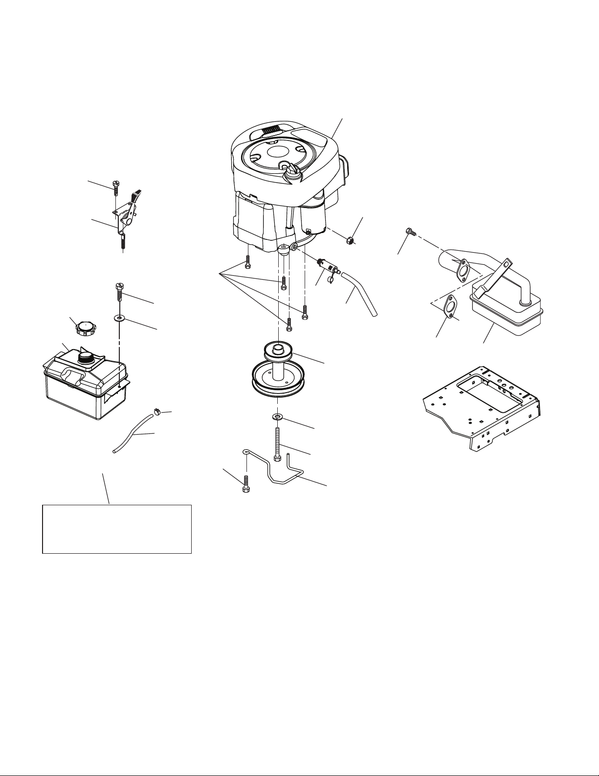
REPAIR PARTS
TRACTOR - - MODEL NUMBER PB19546LT (96042003500), PRODUCT NO. 960 42 00-35
ENGINE
1
21
15
18
20
29
97
96
28
37
84
90
82
85
42
12
45
79
81
69
9
2
OPTIONAL EQUIPMENT
Spark Arrester
engine-bs-1cyl-tex_4
38
Page 39

REPAIR PARTS
TRACTOR - - MODEL NUMBER PB19546LT (96042003500), PRODUCT NO. 960 42 00-35
ENGINE
KEY PART
NO. NO. DESCRIPTION
1 - - - - - - Engine B&S Model No. 31P677
2 137352 Muffler
9 194319 Keeper Belt Engine
12 405140 Pulley Engine
15 407545 Tank Fuel 1.50
18 197725 Cap Asm
20 176636X421 Control Throttle/Choke
21 191611 Screw 10 x 3/4 Single Lead-Hex
28 401137 Fuel Line
29 137180 Spark Arrester Kit
37 123487X Clamp Hose
42 10040700 Washer Lock 7/16
45 73510400 Nut Keps Hex 1/4-20 unc
69 165291 Gasket
79 192334 Screw Socket Hd 5/16-18 x .75
81 148456 Tube Drain Oil Easy
82 181654 Plug Drain Oil
84 17060620 Screw 3/8-16 x 1-1/4
85 173937 Bolt Hex 7/16-20 x 4 x Gr. 5-1.5
90 17000612 Screw 3/8-16 x 1.0
96 19091416 Washer 9/32 x 7/8 x 16 Ga.
97 17670412 Screw 1/4-20 x 3/4
NOTE: All component dimensions given in U.S. inches
1 inch = 25.4 mm
Engine Power Rating Information
The gross power rating for individual gas engine models is labeled in accordance with SAE (Society of Automotive Engineers) code J11940 (Small Engine Power & Torque Rating Procedure), and rating performance has been obtained and
corrected in accordance with SAE J1995 (Revision 2002-5). Actual gross engine power will be lower and is affected by,
among other things, ambient operating conditions and engine-to-engine variability. Given both the wide array of products on which engines are placed and the variety of environmental issues applicable to operating the equipment, the
gas engine will not develop the rated gross power when used in a given piece of power equipment (actual “on-site” or
net horsepower). This difference is due to a variety of factors including, but not limited to, accessories (air cleaner, exhaust, charging, cooling, carburetor, fuel pump, etc.), application limitations, ambient operating conditions (temperature,
humidity, altitude), and engine-to-engine variability. Due to manufacturing and capacity limitations, Briggs & Stratton
may substitute an engine of higher rated power for this Series engine.
39
Page 40

REPAIR PARTS
TRACTOR - - MODEL NUMBER PB19546LT (96042003500), PRODUCT NO. 960 42 00-35
MOWER DECK
47
?MAN4EX?LT?
40
Page 41

REPAIR PARTS
TRACTOR - - MODEL NUMBER PB19546LT (96042003500), PRODUCT NO. 960 42 00-35
MOWER DECK
KEY PART
NO. NO. DESCRIPTION
1 405050x421 Mower Housing
5 4939M Retainer Spring
6 195186 Arm Suspension
7 191611 Screw 10 x 3/4 Single Hex
8 193003 Bolt/Washer asm 7/16-20 unf
11 405380 Blade, 46" Hi-Lift
(For bagging or discharge)
13 192872 Shaft Assembly, Mandrel
14 187281 Housing, Mandrel
15 110485X Bearing, Ball, Mandrel
19 196539 Bolt, Shoulder
21 73680500 Nut, Crownlock 5/16-18 unc
23 192557 Bracket, Deflector
24 105304X Cap, Sleeve
25 197026 Spring, Torsion, Deflector
26 110452X Nut, Push
27 405357 Shield, Deflector
29 131491 Rod, Hinge
30 173984 Screw Thdrol Rolling Wsh Hd
31 187690 Washer, Spacer
32 195945 Pulley, Mandrel
33 400234 Nut, Toplock, Flanged
34 72110612 Bolt Carr Sh. 3/8-16 x 1-1/2 Gr. 5
36 196106 Pulley, Idler, Flat
37 19131316 Washer 13/32 x 13/16 x 16 Ga.
38 199189 Keeper Belt LH Mandrel
40 73900600 Nut, Lock Flg. 3/8-16 unc
42 198410 Spring Torsion Brake
43 197256 Spring Torsion Retainer
46 137729 Screw Thd Roll 1/4-20 x 5/8
47 197250 Bracket Clutch Cable
55 197249 Arm, Idler
56 199092 Spacer, Retainer
57 17000616 Screw Hexwsh Thd 3/8-16 x 1
59 141043 Guard, Tuv Idler (94)
60 400132 Arm Brake Mower
63 199478 Arm Brake Mower
64 405136 Linkage Brake
KEY PART
NO. NO. DESCRIPTION
67 198398X421 Handle, Clutch Cable
68 405143 V-Belt
69 72140505 Bolt Rdhd Sqnk 5/16-18 x 5/8
70 198332 Clutch Asm. Manual
86 197798 Pin Attachment Cable
87 197802 Switch Interlock
113 17000510 Screw 5/16-18
116 4898H Bolt SHLD
117 188606 Wheel Gage
118 73930600 Nut Centerlock 3/8-16 UNC
119 19121414 Washer 3/8 x 7/8 x 14 Ga.
122 197258 Keeper Belt Eng. LH
123 197259 Keeper Belt Eng. RH
129 19131312 Washer 13/32 x 13/16 x 12 Ga.
144 199204 Keeper Belt
145 177968 Pulley Idler
147 401872 Spring Return
151 198331 Bracket Clutch CBL
152 408714 Cable Clutch Manual w/Spr.
186 197799 Arm Acutator CL Cable
187 187800 Lever Control CL Cable
188 195161 Stud Fastener
189 73900500 Nut Lock Hex Flange
193 197801 Spring Plunger Actuator
194 197797 Bearing Control Lever Clutch
195 17000612 Screw Hexwsh Thdr 3/8-16 x 3/4
198 403149 Baffle Center Front
199 403150 Baffle Front RH
240 74520630 Bolt 3/8-16 x 2 x 10 Ga.
241 19133210 Washer 13/32 x 2 x 10 Ga.
- - 192870 Mandrel Assembly (Includes
housing, shaft and shaft hardware
only-pulley not included)
- - 411232 Replacement Mower, Complete
NOTE: All component dimensions given in U.S. inches
1 inch = 25.4 mm
41
Page 42

REPAIR PARTS
TRACTOR - - MODEL NUMBER PB19546LT (96042003500), PRODUCT NO. 960 42 00-35
SEAT
1
8
43
44
41
40
10
21
7
6
37
37
2
3
8
7
21
seat-tex_7-vgt
KEY PART
NO. NO. DESCRIPTION
1 197514 Seat
2 180166 Bracket Pivot Fender
3 140675 Strap, Asm Fender
6 73800600 Nut, Lock W/Ins. 3/8-16 unc
7 124181X Spring, Seat Cprsn
8 171877 Bolt 5/16-18 unc x 3/4 w/Sems
10 196977 Pan, Seat
21 171852 Bolt, Shoulder 5/16-18
KEY PART
NO. NO. DESCRIPTION
37 73800500 Nut, Lock 5/16-18 unc
40 197661 Handle Slide
41 198200 Spring Latch
43 74760612 Bolt 3/8-16 UNC x 3/4
44 19133812 Washer 13/32 x 2 3/8 x 12 Ga.
NOTE: All component dimensions given in U.S. inches
1 inch = 25.4 mm
42
Page 43
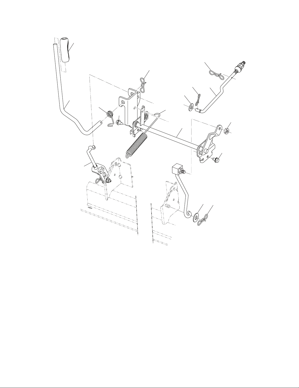
REPAIR PARTS
TRACTOR - - MODEL NUMBER PB19546LT (96042003500), PRODUCT NO. 960 42 00-35
MOWER LIFT
7
87
87
90
89
3
10
97
91
88
2
89
98
100
97
87
lift-tex_5
KEY PART
NO. NO. DESCRIPTION
2 195223 Shaft Asm., Lift
3 195231 Lever Asm., Lift Rh
7 196492X421 Grip, Lever
10 196314 Spring Torsion
87 194209 Pin Cotter 7/16 Bow Tie Lock
88 195303 Spring Lift Assist
KEY PART
NO. NO. DESCRIPTION
89 19191912 Washer Clear Zinc
90 194208 Pin Cotter 5/16 Bow Tie Lock
91 195181 Link Lift Susp Mower Rear
97 17060612 Screw 3/8-16 x .75 Smgml Tap/R.Z
98 195270 Link Lift Susp. Front Mower
100 73930600 Nut Centerlock 3/8 -16 unc
NOTE: All component dimensions given in U.S. inches
1 inch = 25.4 mm
43
Page 44

SERVICE NOTES
44
Page 45

SERVICE NOTES
45
Page 46

SERVICE NOTES
46
Page 47
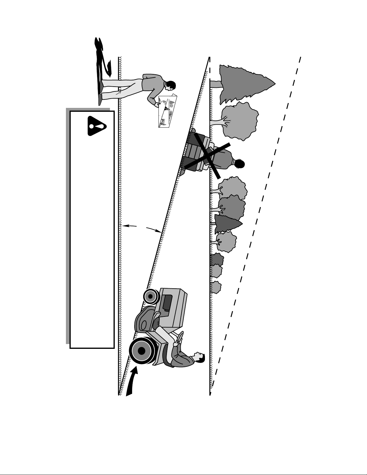
15 DEGREES MAX.
FOLD ALONG DOTTED LINE
THIS IS A 15 DEGREE SLOPE
ONLY RIDE UP AND DOWN HILL,
NOT ACROSS HILL
SUGGESTED GUIDE FOR SIGHTING SLOPES FOR SAFE OPERATION
WARNING: To avoid serious injury, operate your tractor up and
down the face of slopes, never across the face. Do not mow
slopes greater than 15 degrees. Make turns gradually to prevent
tipping or loss of control. Exercise extreme caution when
changing direction on slopes.
1. Fold this page along dotted line indicated above.
2. Hold page before you so that its left edge is vertically parallel to a tree
trunk or other upright structure.
3. Sight across the fold in the direction of hill slope you want to measure.
4. Compare the angle of the fold with the slope of the hill.
47
Page 48

SERVICE
¨
T
E
C
U
Issued January 1980
Revised January 1991
M
H
E
S
POLICY
WARRANTY
T
E
C
U
M
¨
H
E
S
LIMITED WARRANTIES
FOR
NEW PEERLESS GEAR POWER TRAIN COMPONENTS
A. Products Warranted
Peerless Gear and Machine Division of Tecumseh Products Company (“Tecumseh”), subject to the limitations contained below,
will,at its option, repair or replace, without charge for parts or labor only, any part of a new Power Train Component (which as used
herein means and includes the transaxle, gear box, transmission, differential and right angle drives, and any part of the Power Train
Component), EXCEPT any new Power Train Component incorporated in equipment used for commercial or rental purposes, which is
found upon examination by any Tecumseh Authorized Service Outlet or by Tecumseh’s factory in Grafton, Wisconsin, to be DEFECTIVE
IN MATERIAL AND/OR WORKMANSHIP if received by Tecumseh or a Tecumseh Authorized Service Outlet for such examination within
TWO YEARS from the date of sale to the original consumer purchaser of Peerless Series 820, 900, 910, 915, 920, 930 transaxles and
Series 1100 angle drive and ONE YEAR for all other Peerless products. New Power Train Components incorporated in equipment used
for commercial purposes are warranted in the same manner and to the same extent EXCEPT such Power Train Components are warranted for NINETY (90) DAYS ONLY, and must be received by Tecumseh or by a Tecumseh Authorized Service Outlet for such examination within 90 days from the date of sale to the original purchaser. New Power Train Components Incorporated in equipment used for
rental purposes are warranted in the same manner and to the same extent EXCEPT such Power Train Components are warranted for
THIRTY (30) DAYS ONLY, and must be received by Tecumseh or a Tecumseh Authorized Service Outlet within 30 days from the date
of sale to the original purchaser.
B. Products And Items Not Warranted
1. Alterations or Modifications of Power Train Components.
2. Accidents, Normal Maintenance, Failure to follow the Original Equipment Man u fac tur er’s Manual.
This warranty covers only parts of new Power Train Components which are found upon examination to be defective in material or
workmanship as delivered to the original purchaser. This warranty does not cover defects caused by depreciation or damage caused
by normal wear, accidents, improper main te nance, improper use or abuse of the product, failure to follow the instructions contained in
an Instruction Manual for the operation of the Power Train Component and parts. The cost of normal maintenance and replacement of
service items which are not defective shall be paid for by the original purchaser.
C. Securing Warranty Service
Warranty service can be arranged for by contacting either a Tecumseh Authorized Service Outlet (any Tecumseh Registered Service
Dealer, Tecumseh Authorized Service Distributor, or Tecumseh Central Warehouse Distributor) or by contacting Tecumseh, c/o Service
Manager, Engine and Transmission Group Service Division, 900 North Street, Grafton, Wisconsin 53024. Warranty service can only
be performed by a Tecumseh Authorized Service Outlet or by Tecumseh at its factory in Grafton, Wisconsin. At the time of requesting
warranty service, evidence must be presented of the date of sale to the original purchaser. The purchaser shall pay any charges for
making service calls and/or for transporting the product to and from the place where the inspection and/or warranty work is performed.
The purchaser shall be responsible for any damage or loss incurred in connection with the transportation of Power Train Components
and/or part(s) of the Power Train Components submitted for inspection and/or warranty work.
D. Limitation of Damages and Implied Warranties
The foregoing EXPRESSED WARRANTY IS IN LIEU OF ALL OTHER EXPRESS WARRANTIES. Neither Tecumseh nor any of its
affiliates makes any warranties, representations or promises, written or oral, as to the quality of the Power Train Component or any of
its parts, other than as set forth herein.
ANY IMPLIED WARRANTY OF MERCHANTABILITY OR FITNESS FOR A PARTICULAR PURPOSE, TO THE EXTENT THAT
EITHER MAY APPLY TO ANY PART(S) OF POWER TRAIN COMPONENTS, SHALL BE LIMITED IN DURATION TO THE PERIODS
OF THE EXPRESSED WARRANTIES DEFINED IN PARAGRAPH A HEREOF. IN NO EVENT WILL TECUMSEH BE LIABLE FOR ANY
INCIDENTAL, CONSEQUENTIAL OR SPECIAL DAMAGES AND/OR EXPENSES. Some states do not allow limitations on how long
an implied warranty lasts or the exclusion or limitation of incidental or consequential damages, so the above limitation(s) or exclusion(s)
may not apply to you. This warranty gives you specific legal rights and you may also have other legal rights which vary from state to
state.
E. No Dealer Warranty
Tecumseh neither assumes nor authorizes any other person, natural or corporate, to assume for Tecumseh any other obligations or
liabilities in connection with or with respect to any part(s) of a Power Train Component. The seller or dealer of part(s) of a Power Train
Component has no authority, whatsoever, to make any representations or promises on behalf of Tecumseh or to modify the terms or
limitations of Tecumseh’s warranty in any way.
48
 Loading...