

Page 1

Operator ′ s manual Manuel d’utilisation Manual de instrucciones
Saw attachment PA PA 1100
Accessoire de sciage PA PA 1100
Suplemento de sierra PA PA 1100
EEEEnnnngggglllliiiisssshh
GB FR ES
hh
Page 2
KEY TO SYMBOLS
Symbols
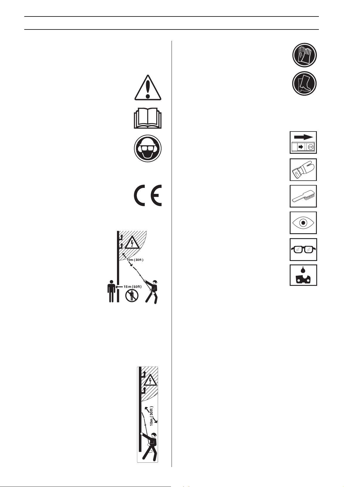
WARNING! The machine can be a dangerous
tool if used incorrectly or carelessly, which can
cause serious or fatal injury to the operator or
others.
Please read the operator’s manual carefully
and make sure you understand the
instructions before using the machine.
Always wear:
• A protective helmet where there is a risk of
falling objects
• Approved hearing protection
• Protective goggles or a visor
This product is in accordance with applicable
EC directives.
.
Always wear approved protective gloves.
Wear sturdy, non-slip boots.
Other symbols/decals on the machine refer to special
certification requirements for certain markets.
Switch off the engine by moving the stop
switch to the STOP position before carrying
out any checks or maintenance.
Always wear approved protective gloves.
Regular cleaning is required.
Saw attachment with shaft PA 1100
This machine is not electrically
insulated. If the machine touches
or comes close to high-voltage
power lines it could lead to death
or serious bodily injury. Electricity
can jump from one point to
another by arcing. The higher the
voltage, the greater the distance
electricity can jump. Electricity
can also travel through branches
and other objects, especially if
they are wet. Always keep a
distance of at least 10 m between
the machine and high-voltage power lines and/or any objects
that are touching them. If have to work within this safe
distance you should always contact the relevant power
company to make sure the power is switched off before you
start work.
Saw attachment without shaft PA
This machine is not electrically insulated. If the
machine touches or comes close to highvoltage power lines it could lead to death or
serious bodily injury. Electricity can jump from
one point to another by arcing. The higher the
voltage, the greater the distance electricity can
jump. Electricity can also travel through
branches and other objects, especially if they
are wet. Always keep a distance of at least 10
m between the machine and high-voltage
power lines and/or any objects that are
touching them. If have to work within this safe
distance you should always contact the relevant
power company to make sure the power is
switched off before you start work.
Visual check.
Protective goggles or a visor must be worn.
Filling with chain oil and adjusting oil flow
2 –
English
Page 3

CONTENTS
Contents Note the following before starting:
KEY TO SYMBOLS
Symbols ....................................................................... 2
CONTENTS
Contents ...................................................................... 3
Note the following before starting: ................................ 3
SAFETY INSTRUCTIONS
Cutting equipment ........................................................ 4
Specification of bar and saw chain .............................. 4
Sharpening your chain and adjusting raker clearance . 5
Tensioning the chain .................................................... 6
Lubricating cutting equipment ...................................... 7
Checking wear on cutting equipment ........................... 8
Safety instructions for using a pruning saw ................. 8
WHAT IS WHAT?
What is what on the saw attachment? (Saw attachment
with shaft PA 1100)....................................................... 11
What is what on the saw attachment? (Saw attachment
without shaft PA)........................................................... 12
ASSEMBLY
Fitting the cutting head (Saw attachment with shaft PA
1100)............................................................................. 13
Fitting the cutting head (Saw attachment without shaft
PA) ................................................................................ 13
Fitting the bar and chain .............................................. 13
Fitting the hanging ring ................................................ 13
Adjusting the harness .................................................. 14
Filling with oil ................................................................ 14
Check before starting ................................................... 14
TECHNICAL DATA
Technical data .............................................................. 15
Bar and chain combinations ........................................ 15
EC-declaration of conformity ........................................ 16
Husqvarna AB has a policy of continuous product
development and therefore reserves the right to modify the
design and appearance of products without prior notice.
Long-term exposure to noise can result in permanent hearing
impairment. So always use approved hearing protection.
Please read the operator’s manual carefully and make sure
you understand the instructions before using the machine.
These instructions supplement the instructions that were
included with the machine. For other procedures, please refer
to the operating instructions for the machine.
WARNING! Under no circumstances may the
design of the machine be modified without
!
the permission of the manufacturer. Always
use genuine accessories. Non-authorized
modifications and/or accessories can result
in serious personal injury or the death of the
operator or others.
WARNING! This accessory may only be used
together with the intended clearing saw/
!
trimmer, see under heading ”Approved
accessories” in chapter Technical data in the
machine’s Operator’s Manual.
The machine is only designed for cutting branches and twigs.
English
– 3
Page 4
SAFETY INSTRUCTIONS
Cutting equipment
This section describes how you can achieve maximum
clearing capacity and extend the life of the cutting attachment
through correct maintenance and using the right type of
cutting attachment.
Only use cutting equipment recommended by us! See
the Technical data section.
Keep the chain’s cutting teeth properly sharpened!
Follow our instructions and use the recommended file
gauge. A damaged or badly sharpened chain increases the
risk of accidents.
WARNING! Always stop the engine before
doing any work on the cutting attachment.
!
This continues to rotate even after the
throttle has been released. Ensure that the
cutting attachment has stopped completely
and disconnect the HT lead from the spark
plug before you start to work on it.
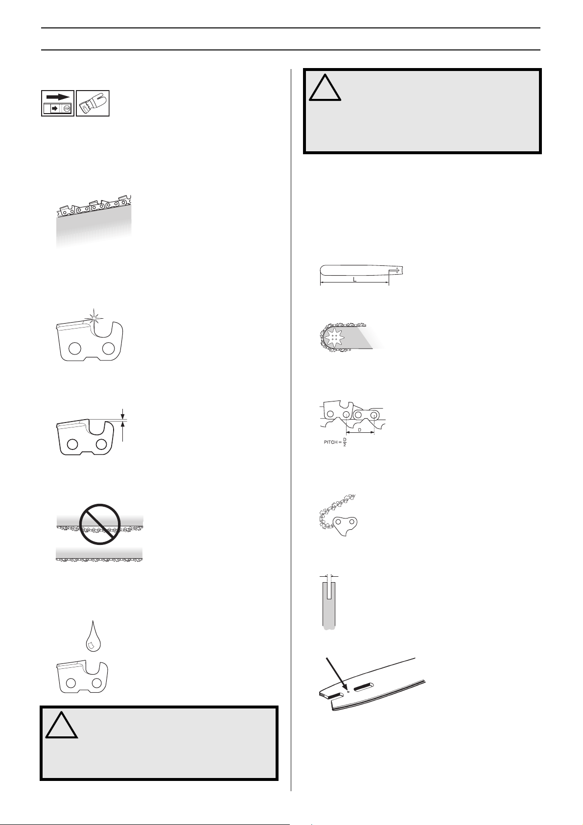
Specification of bar and saw chain
When the cutting attachment supplied with your machine has
to be replaced, because it is worn out or damaged, you must
only fit the types of bar and saw chain recommended by us.
Bar
• Length (inches/cm)
• Number of teeth on bar tip sprocket (T). Small number =
small tip radius = low risk of kickback.
Maintain the correct raker clearance! Follow our
instructions and use the recommended raker gauge. Too
large a clearance increases the risk of kickback.
Keep the chain properly tensioned! If the chain is slack it
is more likely to jump off and lead to increased wear on the
bar, chain and drive sprocket.
Keep cutting equipment well lubricated and properly
maintained! A poorly lubricated chain is more likely to break
and lead to increased wear on the bar, chain and drive
sprocket.
• Chain pitch (inches). The spacing between the drive links
of the chain must match the spacing of the teeth on the
bar tip sprocket and drive sprocket.
• Number of drive links. The number of drive links is
determined by the length of the bar, the chain pitch and
the number of teeth on the bar tip sprocket.
• Bar groove width (inches/mm). The groove in the bar must
match the width of the chain drive links.
• Saw chain oil hole and hole for chain tensioner pin.
4 –
!
English
WARNING! Never use a machine with faulty
safety equipment. The machine’s safety
equipment must be checked and maintained
as described in this section. If your machine
fails any of these checks contact your
service agent to get it repaired.
Page 5
1
5
SAFETY INSTRUCTIONS
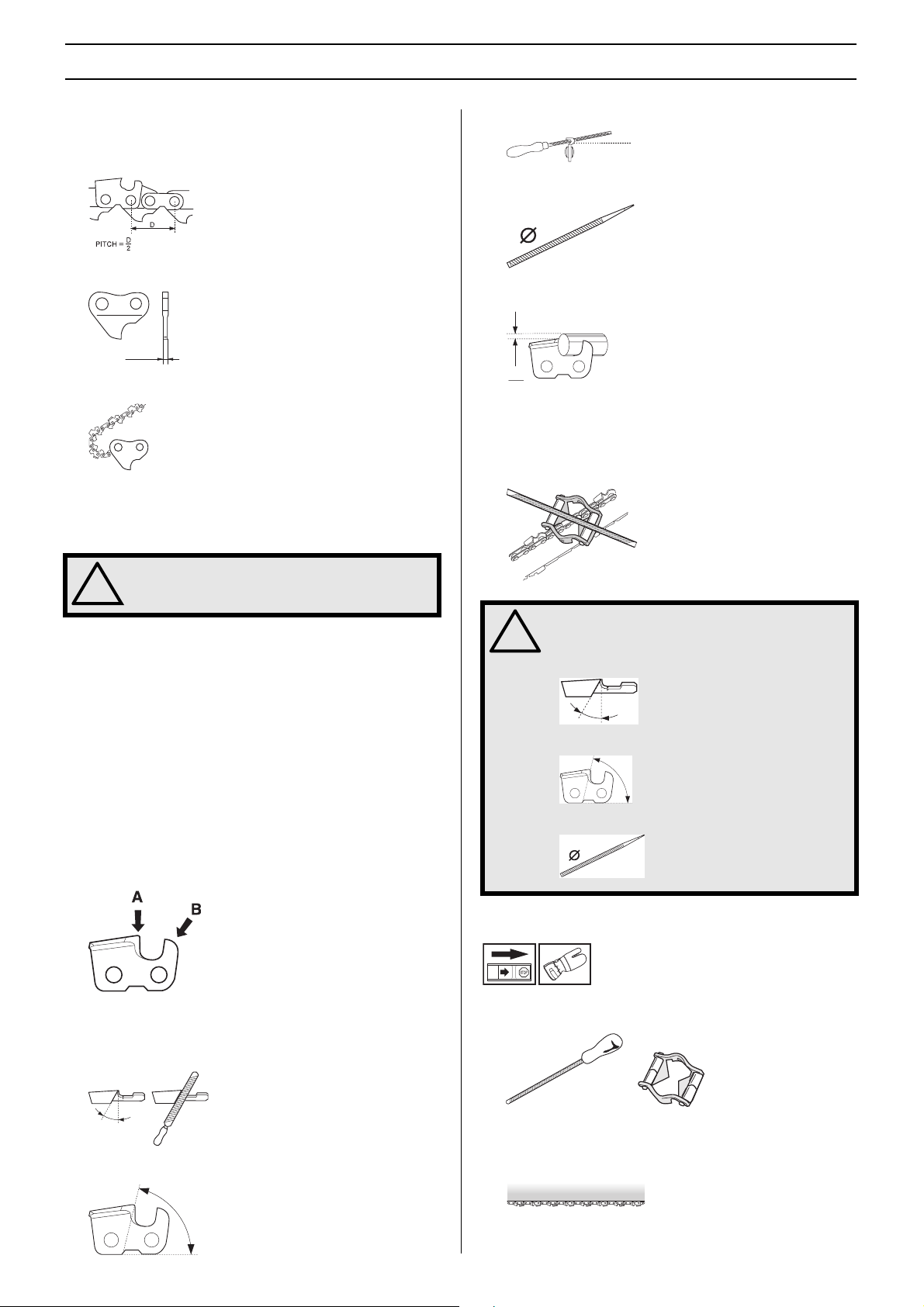
Chain
• Saw chain pitch (inches). (The distance between three
drive links, divided by two.)
• Drive link width (mm/inches)
• Number of drive links.
Sharpening your chain and
adjusting raker clearance
3 File position
4 Round file diameter
5 File depth
It is very difficult to sharpen a chain correctly without the right
equipment. We recommend that you use our file gauge. This
will help you obtain the maximum kickback reduction and
cutting performance from your chain.
WARNING! The risk of kickback is increased
with a badly sharpened chain!
!
General information on sharpening cutting
teeth
• Never use a blunt chain. When the chain is blunt you have
to exert more pressure to force the bar through the wood
and the cuttings will be very small. If the chain is very blunt
it will not produce any cuttings at all. Wood powder would
be the only result.
• A sharp chain eats its way through the wood and
produces long, thick cuttings.
The cutting part of the chain is called the cutting link and
this consists of a cutting tooth (A) and the raker lip (B). The
cutting depth is determined by the difference in height
between the two.
• When you sharpen a cutting tooth there are five important
factors to remember.
1 Filing angle
WARNING! The following faults will increase
the risk of kickback considerably:
!
File angle too large
Cutting angle too small
File diameter too small
Sharpening cutting teeth
• To sharpen cutting teeth you will need a round file and a
file gauge.
2 Cutting angle
• Check that the chain is correctly tensioned. A slack chain
will move sideways, making it more difficult to sharpen
correctly.
English
– 5
Page 6
SAFETY INSTRUCTIONS
• Always file cutting teeth from the inside face outwards.
Reduce the pressure on the return stroke. File all the teeth
on one side of the bar first. Then turn the saw over and file
the remaining teeth from the other side.
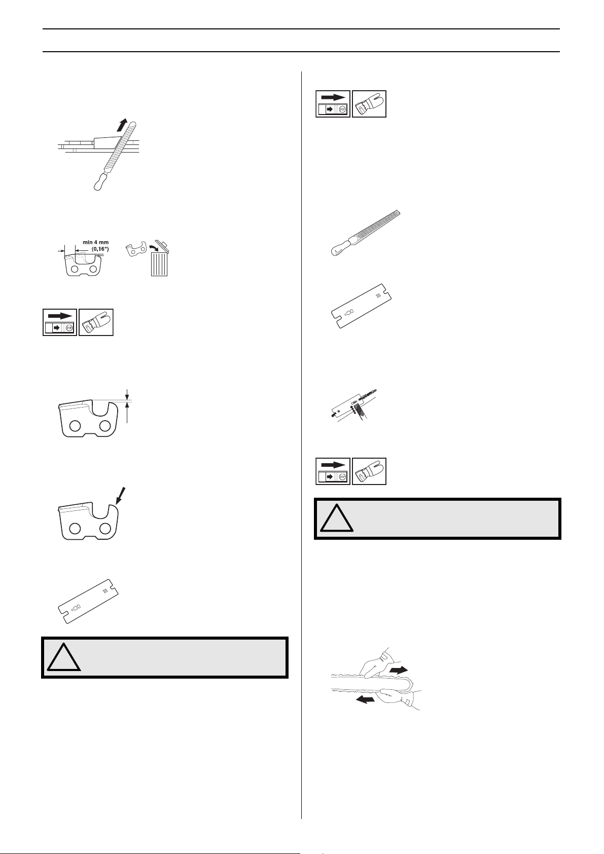
• File all the teeth to the same length. When the length of
the cutting teeth is reduced to 4 mm (0.16") the chain is
worn out and should be replaced.
General advice on setting raker clearance
• When you sharpen the cutting teeth you reduce the raker
clearance (=cutting depth). To maintain optimal cutting
performance you must file back the raker lip to the
recommended height.
Setting the raker clearance
• Before setting the raker clearance the cutting teeth should
be newly sharpened. We recommend that you adjust the
raker clearance every third time you sharpen the chain.
NOTE! This recommendation assumes that the length of
the cutting teeth is not reduced excessively.
• To adjust the raker clearance you will need a flat file and a
raker gauge.
• Place the gauge over the raker lip.
• Place the file over the part of the lip that protrudes through
the gauge and file off the excess. The clearance is correct
when you no longer feel any resistance as you draw the
file over the gauge.
• On a low-kickback cutting link the front edge of the raker
lip is rounded. It is very important that you maintain this
radius or bevel when you adjust the raker clearance.
• We recommend that you use our raker gauge to achieve
the correct clearance and bevel on the raker lip.
WARNING! The risk of kickback is increased
if the raker clearance is too large!
!
Tensioning the chain
WARNING! A slack chain may jump off and
cause serious or even fatal injury.
!
• The more you use a chain the longer it becomes. It is
therefore important to adjust the chain regularly to take up
the slack.
• Check the chain tension every time you refuel. NOTE! A
new chain has a running-in period during which you
should check the tension more frequently.
• Tension the chain as tightly as possible, but not so tight
that you cannot pull it round freely by hand.
6 –
English
Page 7

SAFETY INSTRUCTIONS
1 Undo the bar nut.
2 Raise the tip of the bar and stretch the chain by tightening
the chain tensioning screw using the combination
spanner. Tighten the chain until it does not sag from the
underside of the bar.
Filling with chain oil
The oil pump is preset at the factory to meet most lubrication
requirements. A full oil tank will last about half as long as a full
tank of fuel. You should therefore check the level of oil in the
oil tank regularly to avoid damage to the saw chain and bar
that could occur due to lack of lubrication.
3 Use the combination spanner to tighten the blade nut
while holding up the tip of the bar. Check that you can pull
the saw chain round freely by hand.
Lubricating cutting equipment
WARNING! Poor lubrication of cutting
equipment may cause the chain to snap,
!
which could lead to serious, even fatal
injuries.
Chain oil
Checking chain lubrication
Check the chain lubrication each time you refuel.
Aim the tip of the bar at a light coloured surface about 20 cm
(8 inches) away. After 1 minute running at 3/4 throttle you
should see a distinct line of oil on the light surface.
Adjusting chain lubrication
When cutting dry or hard species of wood it may be
necessary to increase lubrication. Turn the adjuster screw
anticlockwise to increase the oil flow. Remember that this will
increase oil consumption, check the level in the oil tank
regularly. Turn the adjuster screw clockwise to decrease the
oil flow.
• Chain oil must demonstrate good adhesion to the chain
and also maintain its flow characteristics regardless of
whether it is warm summer or cold winter weather.
• As a chain saw manufacturer we have developed an
optimal chain oil which, with its vegetable oil base, is also
biodegradable. We recommend the use of our own oil for
both maximum chain life and to minimise environmental
damage.
• If our own chain oil is not available, standard chain oil is
recommended.
• In areas where oil specifically for lubrication of saw chains
is unavailable, ordinary EP 90 transmission oil may be
used.
• Never use waste oil! This is dangerous for yourself, the
machine and the environment.
What to do if lubrication does not work:
1 Check that the oil channel in the bar is not obstructed.
Clean if necessary.
English
– 7
Page 8

SAFETY INSTRUCTIONS
2 Check that the oil channel in the gear housing is clean.
Clean if necessary.
3 Check that the bar tip sprocket turns freely. If the chain
lubrication system is still not working after carrying out the
above checks you should contact your service workshop.
Checking wear on cutting
equipment
Chain
Check the chain daily for:
• Visible cracks in rivets and links.
Vibration damping system
Check regularly that the vibration damping element is free
from cracks. Check regularly the degree of wear to the rubber
dampers. Replace them if worn.
Bar
Check regularly:
• Whether there are burrs on the edges of the bar. Remove
these with a file if necessary.
• Whether the groove in the bar has become badly worn.
Replace the bar if necessary.
• Whether the chain is stiff.
• Whether rivets and links are badly worn.
We recommend you compare the existing chain with a new
chain to decide how badly the existing chain is worn.
When the length of the cutting teeth has worn down to only 4
mm the chain must be replaced.
Chain drive sprocket
Regularly check the degree of wear on the drive sprocket.
Replace if wear is excessive.
• Whether the tip of the bar is uneven or badly worn. If a
hollow forms on the underside of the bar tip this is due to
running with a slack chain.
To prolong the life of the bar you should turn it over daily.
WARNING! A faulty cutting attachment may
increase the risk of accidents.
!
Safety instructions for using a
pruning saw
WARNING! The machine can cause serious
personal injury. Read the safety instructions
!
carefully. Learn how to use the machine.
8 –
English
WARNING! Cutting tool. Do not touch the
tool without first switching off the engine.
!
CAUTION! Please read the operator’s manual carefully and
make sure you understand the instructions before using the
machine.
Page 9

SAFETY INSTRUCTIONS
Personal protection
• Always wear boots and other equipment described under
the heading Personal protective equipment in the
machine’s Operator’s Manual.
• Always wear working clothes and heavy-duty long
trousers.
• Never wear loose clothing or jewellery.
• Make sure your hair does not hang below shoulder level.
Safety instructions regarding the
surroundings
• Never allow children to use the machine.
• Ensure that no-one comes closer than 15 m while you are
working.
• Never allow anyone else to use the machine without first
ensuring that they have understood the contents of the
operator’s manual.
• Never work from a ladder, stool or any other raised
position that is not fully secured.
• When the engine is switched off, keep your hands and feet
away from the cutting attachment until it has stopped
completely.
• Watch out for stumps of branches that can be thrown out
during cutting.
• Always lay the machine on the ground when you are not
using it.
• Check the working area for foreign objects such as
electricity cables, insects and animals, etc, or other
objects that could damage the cutting attachment, such
as metal items.
• If any foreign object is hit or if vibrations occur stop the
machine immediately. Disconnect the HT lead from the
spark plug. Check that the machine is not damaged.
Repair any damage.
• If anything gets caught up in the cutting attachment while
you are working, switch off the engine and let it stop
completely before cleaning the cutting attachment.
Safety instructions after completing work
• The transport guard should always be fitted to the cutting
attachment when the machine is not in use.
• Make sure the cutting attachment has stopped before
cleaning, carrying out repairs or an inspection.
Disconnect the HT lead from the spark plug.
• Always wear heavy-duty gloves when repairing the cutting
attachment. This is extremely sharp and can easily cause
cuts.
Safety instructions while working
• Always ensure you have a safe and stable working
position.
• Always use both hands to hold the machine. Hold the
machine at the side of your body.
• Use your right hand to control the throttle setting.
• Make sure that your hands and feet do not come near the
cutting attachment when the engine is running.
• Store the machine out of reach of children.
• Use only original spare parts for repairs.
Basic working techniques
• Hold the machine as close to your body as possible to get
the best balance.
• Make sure that the tip does not touch the ground.
• Do not rush the work, but work steadily until all the
branches have been cut back cleanly.
English
– 9
Page 10

SAFETY INSTRUCTIONS
• Always slow the engine to idle speed after each working
operation. Long periods at full throttle without any load on
the engine can lead to serious engine damage.
• Always work at full throttle.
• Let the engine drop back to idle speed between each cut.
Long periods at full throttle can cause serious damage to
the centrifugal clutch.
WARNING! Never stand directly underneath
a branch that is being cut. This could lead to
!
serious or even fatal personal injury.
Observe great care when working close to overhead power
lines. Falling branches can result in short-circuiting.
WARNING! Observe the applicable safety
regulations for work in the vicinity of
!
overhead power lines.
WARNING! This machine is not electrically
insulated. If the machine touches or comes
!
close to high-voltage power lines it could
lead to death or serious bodily injury.
Electricity can jump from one point to
another by arcing. The higher the voltage,
the greater the distance electricity can jump.
Electricity can also travel through branches
and other objects, especially if they are wet.
Always keep a distance of at least 10 m
between the machine and high-voltage
power lines and/or any objects that are
touching them. If have to work within this
safe distance you should always contact the
relevant power company to make sure the
power is switched off before you start work.
• Cut large branches in sections so that you have better
control over where they fall.
• Never cut through the swelling at the root of the branch as
this will slow down healing and increase the risk of fungal
attack!
• Use the stop at the base of the cutting head to provide
support during cutting. This will help prevent the cutting
attachment from ”jumping” on the branch.
• Make an initial cut on the underside of the branch before
cutting through the branch. This will prevent tearing of the
bark, which could lead to slow healing and cause
permanent damage to the tree. The cut should not be
deeper than 1/3 of the branch thickness to prevent
jamming. Keep the chain running while you withdraw the
cutting attachment from the branch to prevent it jamming.
WARNING! This machine has a long reach.
Make sure that no people or animals come
!
closer than 15 m when the machine is
running.
• Whenever possible position yourself so that you can make
the cut at right angles to the branch.
• Do not work with the shaft held straight out in front of you
(like a fishing rod) as this increases the apparent weight of
the cutting attachment.
• Use the harness to support the weight of the machine and
make it easier to handle.
• Make sure you have a firm footing and that you can work
without being hampered by branches, stones and trees.
WARNING! Never activate the throttle
without having the cutting attachment in full
!
view.
10 –
English
Page 11

WHAT IS WHAT?
12
10
11
9
8
4
7
13
14
11
2
1
3
6
5
15
What is what on the saw attachment? (Saw attachment with shaft PA 1100)
1 Bevel gear
2 Chain lubrication adjustment screw
3 Shaft (1100 mm)
4 Harness support hook
5 Protective guard for saw chain
6 Bar nut
7 Chain tensioning screw
8 Chain
9 Bar
10 Chain oil tank
11 Filling with chain oil
12 Operator ′ s manual
13 Transport guard
14 Combination spanner
15 Harness
English
– 11
Page 12

WHAT IS WHAT?
11
8
10
10
2
1
7
9
5
4
3
6
14
12
13
What is what on the saw attachment? (Saw attachment without shaft PA)
1 Bevel gear
2 Chain lubrication adjustment screw
3 Harness support hook
4 Protective guard for saw chain
5 Bar nut
6 Chain tensioning screw
7 Chain
8 Bar
9 Chain oil tank
10 Filling with chain oil
11 Operator′s manual
12 Transport guard
13 Combination spanner
14 Harness
12 – English
Page 13

ASSEMBLY
Fitting the cutting head
(Saw attachment with shaft PA 1100)
• Fit the cutting head on the shaft so that the screw (A) is
aligned with the hole in the shaft as shown.
B
A
• Tighten screw A.
• Tighten screw B.
CAUTION! Make sure that the drive shaft inside the shaft
engages with the cut-out in the cutting head.
Fitting the cutting head
(Saw attachment without shaft PA)
Fitting the bar and chain
• Unscrew the bar nut and remove the protective cover.
• Fit the bar over the bar bolt. Place the bar in its rearmost
position. Place the chain over the drive sprocket and in the
groove on the bar. Begin on the top side of the bar.
• Make sure that the edges of the cutting links are facing
forward on the top edge of the bar.
• Fit the cover and locate the chain adjuster pin (A) in the
hole in the bar. Check that the drive links of the chain fit
correctly on the drive sprocket (B) and that the chain is in
the groove in the bar (C). Tighten the bar nut finger-tight.
• Tension the chain by turning the chain tensioning screw
clockwise using the combination spanner. The chain
should be tensioned until it does not sag from the
underside of the bar.
• Remove the mitre gear from the shaft.
• Fit the cutting attachment to the shaft.
B
A
• Tighten screw A.
• Tighten screw B.
CAUTION! Make sure that the drive shaft inside the shaft
engages with the cut-out in the cutting head.
• The chain is correctly tensioned when it does not sag from
the underside of the bar, but can still be turned easily by
hand. Hold up the bar tip and tighten the bar nuts with the
combination spanner.
• When fitting a new chain, the chain tension has to be
checked frequently until the chain is run-in. Check the
chain tension regularly. A correctly tensioned chain
ensures good cutting performance and long life.
Fitting the hanging ring
Fit the hanging ring between the rear handle and the loop
handle. Position the hanging ring so that the machine is
balanced and comfortable to work with.
English – 13
Page 14

ASSEMBLY
Adjusting the harness
You should always use the harness with the machine to give
maximum control over the machine and reduce the risk of
fatigue in your arms and back.
• Put on the harness.
• Hook the machine onto the harness support hook.
• Adjust the length of the harness so that the support hook
is roughly level with your right hip.
Filling with oil
• Open the cap on top of the bar head
Check before starting
• Inspect the working area. Remove any objects that could
be thrown out.
• Check the cutting attachment. Never use blunt, cracked or
damaged equipment.
• Check that the machine is in perfect working order. Check
that all nuts and screws are tight.
• Make sure the chain is adequately lubricated. See
instructions under the heading Lubricating the cutting
attachment.
• Check that the cutting attachment always stops when the
engine is idling.
• Only use the machine for the purpose it was intended for.
• Make sure the handle and safety features are in order.
Never use a machine that has any parts missing or has
been modified in relation to the specification.
• Fill with Husqvarna saw chain oil.
• Refit the cap.
14 – English
Page 15

Technical data
TECHNICAL DATA
Technical data
Saw attachment without
shaft PA
Saw attachment with shaft
PA 1100
Lubrication system
Oil tank capacity, litre 0,22 0,22
Weight
Weight without fuel, cutting attachment and guard, kg 0,8 1,4
Noise levels
(see note 1)
Equivalent noise pressure level at the user’s ear, measured
according to EN ISO 11680-1, dB(A) 95 96
Equivalent noise power level at the user’s ear, measured
according to EN/ISO 11680-1 and ISO 10884, dB(A) 106 106
Vibration levels
Vibration levels on the handles, measured according to
EN/ISO 11680 m/s
2
When idling, rear/front handles: 1,0/3,0 1,2/2,3
At max. speed, rear/front handles: 5,5/3,6 6,0/5,5
Note 1: Equivalent sound pressure level is calculated as the time-weighted energy total for sound pressure levels under various
working conditions with the following time distribution: 1/2 idling and 1/2 max speed.
Bar and chain combinations
The following combinations are CE approved.
Bar Chain
Length, inches Pitch, inch
Max. no of teeth
on tip sprocket
10 3/8 7 T Husqvarna S 36/Oregon 91 VG
12 3/8 7 T
10 3/8 7 T Oregon 90SG
12 3/8 7 T
D
D
_
PITCH =
2
L
English – 15
Page 16

TECHNICAL DATA
EC-declaration of conformity
(Applies to Europe only)
We, Husqvarna AB, SE-561 82 Huskvarna, Sweden, tel +46-36-146500, declare that this saw attachment from 2002’s serial
numbers and onwards (the year is clearly stated in plain text on the type plate, with subsequent serial number), complies with the
requirements of the COUNCIL’S DIRECTIVE:
of June 22, 1998 ”relating to machinery” 98/37/EC, annex IIA.
The following standards have been applied: EN 292-2, EN ISO 11680-1
Notified body: 0404, SMP Svensk Maskinprovning AB, Fyrisborgsgatan 3, SE-754 50 Uppsala, Sweden, has carried out EC type
examination in accordance with the machinery directive’s (98/37/EC) article 8, point 2c. The certificate for EC type examination in
accordance with annex VI, has number: 404/02/858
The supplied saw attachment conforms to the example that underwent EC type examination.
Huskvarna January 3, 2002
Bo Andréasson, Development manager
16 – English
Page 17

´®z+H8r¶0_¨
1140248-26
´®z+H8r¶0_¨
20
2004-02-05
 Loading...