


Oper ator ′ s manual
P 520D W ith cabin
P 525D With cabin
Please r ead the operator’s manual carefully and make sure you understand the
instructions before using the machine.
EEEEnnnngggglllliiiisssshh
hh
2
>10
KEY T O SYMBOLS
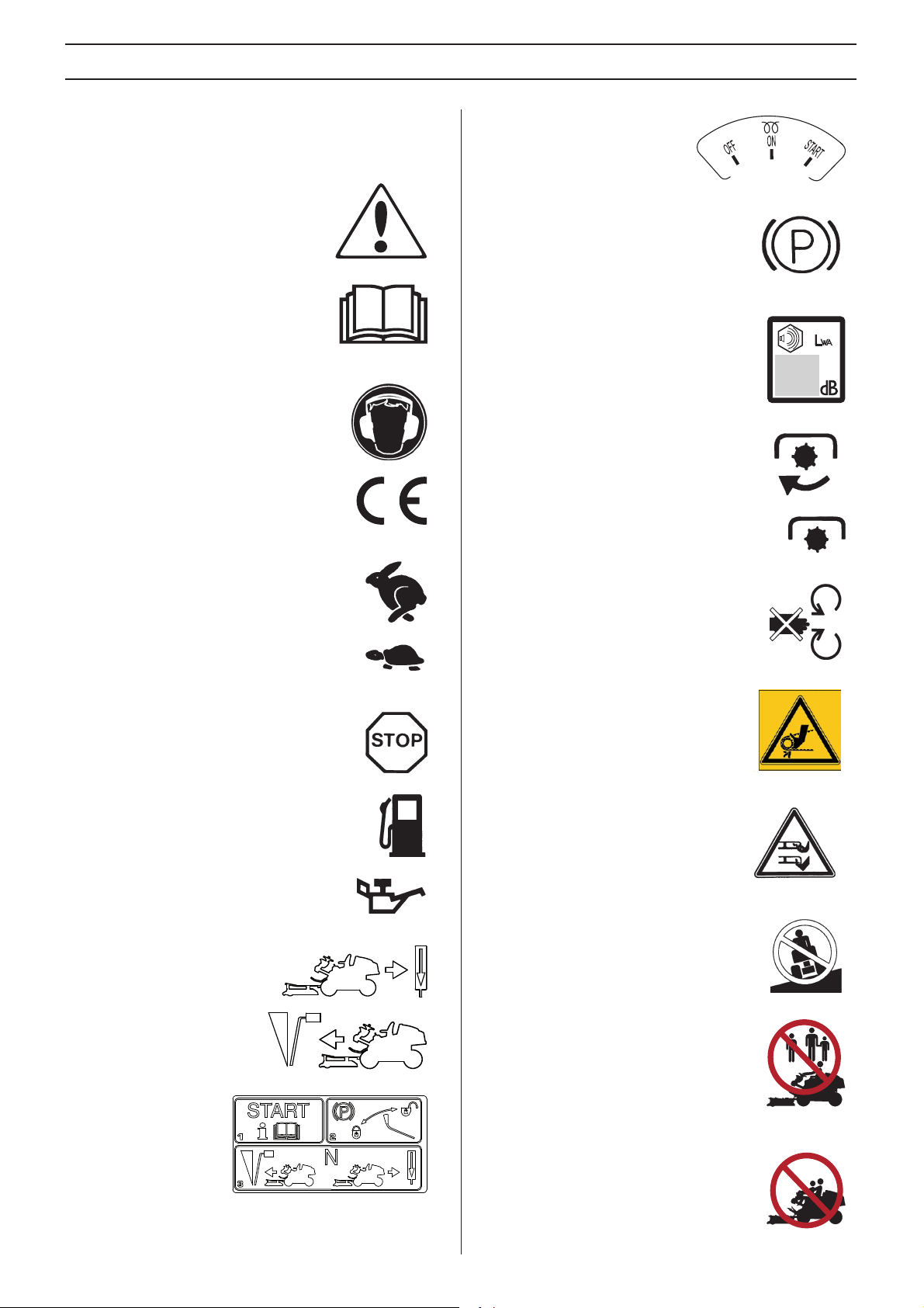
Symbols
These symbols are on the machine and in the instr uctions.
WARNING! Careless or incorrect use can
result in serious or fatal injury to the
operator or others.
Please read the operator’s manual
carefully and make sure you understand
the instructions before using the machine.
Always wear:
• Approved hearing protection
This product is in accordance with applicable
EC directives.
Fast
Slow
Stop the engine.
Ignition
Parking brake
Noise emission to the environment
according to the European Community’s
Directive. The machine’s emission is
specified in the Technical data chapter and
on the label.
Connecting the power take-off (PTO).
Disengaging the power take-off (PTO)
Warning: rotating parts. Keep hands and feet
clear.
Watch your hands and other body parts
so they do not get caught and crushed
between the belt and belt pulley.
Fuel
Oil pressure
Backwards
Forwards
Starting instructions
Rotary blades Keep hands and feet
away from under the hood when the
engine is running
Never drive across a slope
Never use the machine if persons,
especially children, or animals, are in the
vicinity
Never carry passengers on the machine or
equipment
–
English
W
W
KEY T O SYMBOLS
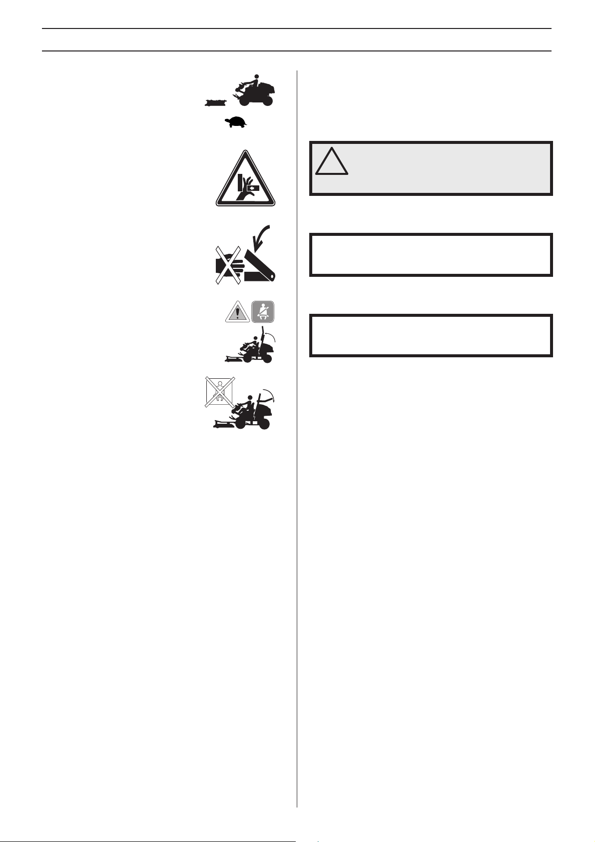
Drive very slowly if no cutting unit is
fitted
Risk of crush injuries!
Danger of crushing between the lift arms
and base plate.
If the frame is folded up, the safety belt must
be used.
Explanation of warning le vels
The w arnings are graded in three levels.
ARNING!
ARNING! Used if there is a risk of serious
injury or death for the operator or damage to
!
the surroundings if the instructions in the
manual are not followed.
IMPORTANT!
IMPOR TANT! Used if there is a risk of injury to the operator
or damage to the surroundings if the instructions in the
manual are not followed.
CAUTION!
CAUTION! Used if there is a risk of damage to materials or
the machine if the instructions in the manual are not
followed.
If the frame is folded down the safety
belt should NOT be used.
English
– 3

4
MA
ST
CONTENTS
Contents
KEY TO SYMBOLS
Symbols ....................................................................... 2
Explanation of warning levels ...................................... 3
CONTENTS
Contents ...................................................................... 4
Ser vice journal
Pre-deliv ery service ..................................................... 6
After the first 25 hours ................................................. 6
PRESENT ATION
Dear Customer , ............................................................ 7
Driving and transport on public roads .......................... 7
Towing .......................................................................... 7
Use .............................................................................. 7
Insure your Rider ......................................................... 7
Good service ................................................................ 8
WHA T IS WHAT?
What is what on the machine? ..................................... 9
CHINE´S SAFETY EQUIPMENT
Gener al ........................................................................ 10
Ignition key ................................................................... 10
Safety circuit ................................................................ 10
Warning lamp ............................................................... 10
Speed limiter ................................................................ 10
Parking brake ............................................................... 11
ROPS (Roll Over Protective Structure) ........................ 11
Safety belt ................................................................... 11
Counter weight ............................................................. 12
Muffler .......................................................................... 12
Protective covers .......................................................... 12
ASSEMBLING AND ADJUSTMENTS
Saf ety when assembling and settings .......................... 13
Cutting unit ................................................................... 13
Fitting the cutting head ................................................ 14
Removing the cutting unit ............................................ 15
Seat adjustment ........................................................... 16
Auxiliary lift system settings ......................................... 16
Dismantling the doors .................................................. 16
Dismantling the cab ..................................................... 17
Assembling the ROPS (Roll Over Protective Structure) 18
Lowering the ROPS (Roll Over Protective Structure) .. 18
FUEL HANDLING
Gener al ........................................................................ 19
Fuel .............................................................................. 19
Winter fuel .................................................................... 19
Fueling ......................................................................... 19
Transport and storage .................................................. 19
OPERA TING
Gener al safety precautions .......................................... 20
Personal protective equipment ..................................... 20
Other protective equipment .......................................... 20
Work safety .................................................................. 21
Instrument panel .......................................................... 21
Driving the Rider .......................................................... 21
Lights and power outlet ................................................ 23
Controls - Cabin ........................................................... 23
Controls - Control panel ............................................... 24
Heating and fan system ................................................ 24
Transport and storage .................................................. 24
Transportation and storage of the cabin ....................... 25
Transport with engine off .............................................. 25
Bypass valves .............................................................. 25
ARTING AND STOPPING
Bef ore starting .............................................................. 26
Start the engine ............................................................ 26
Starting the engine with a weak battery ....................... 27
Braking ......................................................................... 28
Stop the engine ............................................................ 28
MAINTENANCE AND SER VICE
Maintenance schedule ................................................. 29
General ........................................................................ 30
Cleaning ....................................................................... 30
Checking the engine’s cooling air intake ...................... 30
Cleaning the radiator cell package ............................... 30
Cleaning the air filter .................................................... 30
Cleaning the engine and muffler .................................. 31
Removing of the machine hoods .................................. 31
Adjustment of pump and alternator belt ....................... 31
Change pump and alternator belt ................................. 31
Adjusting the parking brake .......................................... 32
Replacing the light bulbs .............................................. 32
Main fuse ...................................................................... 33
Service position for the cutting unit .............................. 34
–
English

CONTENTS
Cutting height and tilt angle adjustment. ...................... 36
Replacing the cutting unit belts .................................... 37
Checking the blades .................................................... 38
Replacing the blades ................................................... 38
Removing the BioClip plug ........................................... 38
Adjustment of PTO belts .............................................. 38
Change PTO belts ....................................................... 39
Change coolant ............................................................ 40
Inspecting the muffler ................................................... 40
Checking the tyre pressure .......................................... 40
Check the battery ......................................................... 41
Replacement of fuel filter ............................................. 41
Replacing the air filter .................................................. 41
Changing the fan system inlet filter .............................. 42
The cutting unit bevel gear ........................................... 42
Checking the engine’s oil level. .................................... 42
Replacing the engine oil .............................................. 43
Changing the oil filter ................................................... 43
Check the hydraulic system oil level ............................ 43
Check the oil level in the transmission gearboxes ....... 43
Lubrication
Lubr ication schedule .................................................... 44
General ........................................................................ 44
Accessories ................................................................. 45
Pivot wheel bearings ................................................... 45
Universal drive shaft joints ........................................... 45
Cutting unit bracket ...................................................... 45
Lift arm rear bearings ................................................... 45
Lift cylinder ................................................................... 45
The drive shaft front support bearing ........................... 45
The drive shaft rear support bearing ............................ 45
Steering cylinder .......................................................... 45
Joint bearing ................................................................ 46
Link brace .................................................................... 46
Knobs for setting the cutting height .............................. 46
Driver seat .................................................................... 46
Lubricating the cables .................................................. 46
Throttle and choke cables, lever bearings ................... 46
Lubricate the parking brake wire .................................. 46
roubleshooting schedule
TECHNICAL DATA
Ride-on mo wer dimensions ......................................... 51
Cabin dimensions ........................................................ 52
Cabin support dimensions ........................................... 52
EC Declaration of Conformity ...................................... 53
T
English
– 5

6
1
1
Ser vice journal
Pre-deliver y service
Charge the battery for at least 4 hours at max. 5
amp.
2 Check coolant level and antifreeze.
3 Check and adjust tyre pressure (150 kPa, 1,5 bar,
21,8 PSI).
4 Make sure the correct amount of oil is in the
cutting unit's bevel gear.
5 Check that the right amount of oil is in the engine.
6 Check that there is oil in the transmission’s oil
tank.
7 Fit cutting unit.
8 Adjust cutting unit:
Adjust cutting unit so that rear edge is about 6-9
mm higher than front edge.
14 Tell customer about:
The requirement and advantages of servicing the
machine according to the service plan
Servicing and the influence of this journal on the
second-hand value of the machine.
The transmission warranty is only valid if front
and rear wheel rotation speed has be checked in
accordance with the service schedule. Adjust if
necessary according to the table values specified in the
workshop manual. Performed by authorized servicing
dealer. The system will be damaged if this adjustment is
not carried out.
At temperatures below 0 ° C, the machine must
be warmed up for at least 10 minutes for the
hydraulic oil and transmission to get hot.
Otherwise there is a risk of the transmission breaking
down thereby reducing the service life of the transmission.
Range of applications for BioClip function.
Complete proof of sale etc.
Pre-delivery service carried out. No outstanding
problems. Certified:
Date:
Conduct a function test of the cutting deck height
adjustment. - Combi 132 X, Combi 155 X
9 Lubricate the universal drive shaft with grease.
10 Connect battery.
11 Fill with fuel and start engine.
12 Check that machine does not move in neutral.
13 Check:
Forward drive.
Reverse drive.
Operation of blades.
Seat safety switch.
Mileage:
Signature:
Label:
After the fi rst 25 hours
Change the engine oil and oil filter
2 Changing oil in transmission gearboxes (front and
rear).
3 Replace the engine’s hydraulic oil filter
Safety switch for parking brake.
–
English
4 Check front and rear wheel rotation speed
according to the service schedule.

T
PRESENT A TION
Dear Customer ,
Thank y ou for choosing a Husqvarna Rider. Husqvarna Riders are built to a unique design with a front-mounted cutting unit and a
patented articulated steering. Riders are designed for maximum efficiency even in small or confined areas. The closely grouped
controls and pedal-operated hydrostatic transmission also contribute to the performance of this machine.
This operator’s manual is a valuable document. By following its instructions (on operation, service, maintenance, etc.) you will
significantly extend the life of the machine and even its second-hand value.
When you sell your Rider, make sure you pass on the operator’s manual to the new owner.
A service journal accompanies the operator’s manual. Ensure that service and repair work is documented. A well-documented
service history reduces the costs of seasonal maintenance and influences the second-hand value of the machine. Bring the service
journal when bringing the machine to a workshop for a service.
Driving and transpor t on public roads
Chec k the relevant road traffic regulations before driving the machine on a public road. If transporting the machine on another
vehicle always use approved securing devices and make sure that the machine is securely held.
owing
When y our machine is equipped with a hydrostatic transmission you should only tow the machine over short distances and at a
low speed, otherwise there is a risk of damaging the transmission.
The transmission must be disengaged when towing, see instructions under the heading Bypass valves.
Use
This r ide-on mower is designed to mow grass on open and level ground surfaces. In addition, there is a number of accessories
recommended by the manufacturer that broadens the application area. Please contact your dealer for more information about
which accessories are available. The machine may only be used with the equipment recommended by the manufacturer. All other
types of use are incorrect. Compliance with and strict adherence to the conditions of operation, service and repair as specified by
the manufacturer also constitute essential elements of the intended use.
IMPORTANT! The transmission warranty is only valid if front and rear wheel rotation speed has be checked in accordance with
the service schedule. Adjust if necessary according to the table values specified in the workshop manual. Performed by
authorized servicing dealer. The system will be damaged if this adjustment is not carried out.
This machine should be operated, serviced and repaired only by persons who are familiar with its particular characteristics and
who are acquainted with the relevant safety procedures.
Accident prevention regulations, all other generally recognised regulations on safety and occupational medicine, and all road traffic
regulations must be observed at all times.
Any arbitrary modifications carried out to this machine may relieve the manufacturer of liability for any resulting damage or injury.
Insure y our Rider
Chec k the insurance coverage for your new Rider.
• Contact your insurance company.
• You should have fully comprehensive insurance including: third party, fire, damage, theft and liability
English
– 7

8
PRESENT A TION
Good ser vice
Husqv arna products are sold all over the world and ensures that you, the customer, get the best support and service. For example,
before this machine was delivered it was inspected and adjusted by your dealer. See the certificate in the Service Journal in this
manual.
IMPORTANT! All service intervals are described in the service journal. Ensure service is carried out at the right time.
When you need spare parts or advice on service issues, warranty terms, etc., contact:
Name: Dealer:
This operator’s manual belongs to the machine with the
manufacturing number (serial number):
PNC: Engine
On the machine's rating plate you will find the following information:
• The machines type designation.
• The manufacturer’s type number.
• The machine’s serial number.
State the type designation and serial number when ordering spare parts.
Transmission
–
English
WHA T IS WHA T?
1
1
23
2
22
21
4
3
20
19
6
5
7
18
8
10
9
11
12
17
16
13
14
15
14
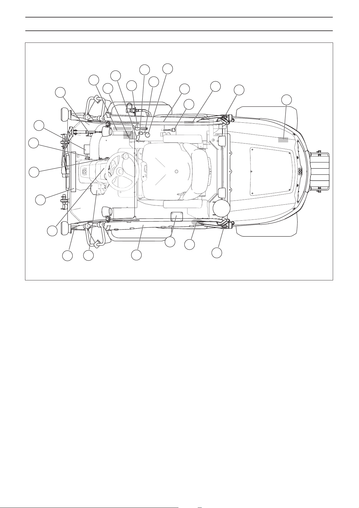
What is what on the mac hine?
High and low speed catches
2 Speed limiter for driving forward
3 Speed limiter for reversing
4 Heating controls
5 Window washer fluid container
6 Parking brake
7 Lever for hydraulic lift of attachments
8 Function button for accessories with extra hydraulics
9 Cutting height control
10 Control for cutting unit drive
11 Emergency exit
12 Throttle trigger
13 Product and serial number plate
14 Cover lock
15 Bypass valve rear axle
16 Fuel cap
17 Fuel gauge
18 Driver’s door
19 Controls - Control panel
20 Venting stay
21 Instrument panel
22 Air distributor
23 Ignition lock
English
– 9
MA CHINE´S SAFETY EQ UIPMENT
10
•
General
WARNING! Never use a machine that has
faulty safety equipment!
!
If your machine fails any checks contact
your service agent to get it repaired.
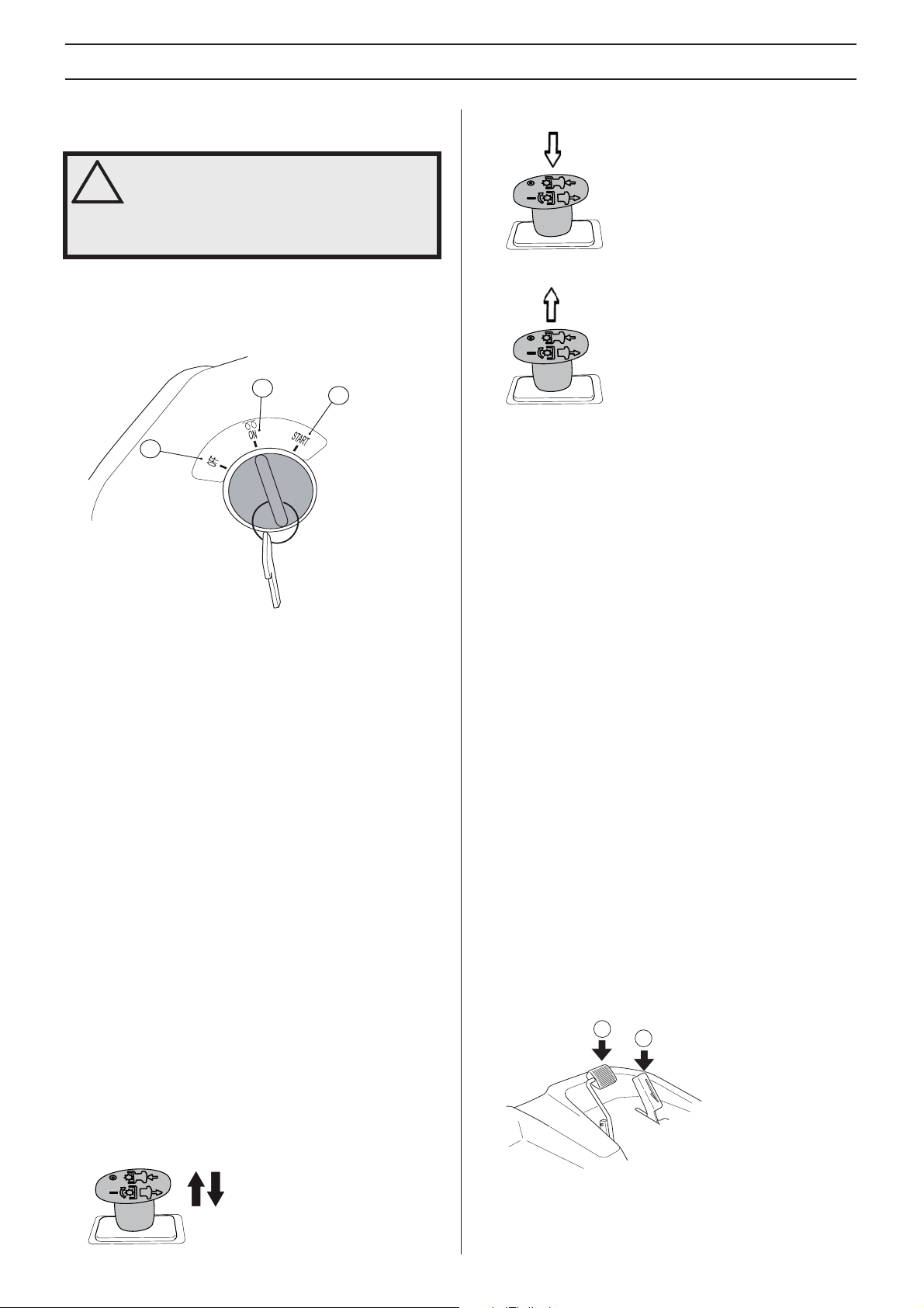
Ignition ke y
The ignition k ey is used to turn the engine on and off together
with all electrical functions except the power outlet.
2
1
3
• Push in the lever to disengage the blades.
• Pull out the lever to engage the drive of the blades.
Saf ety circuit check
• Check daily to ensure that the safety system works by
attempting to start the engine when one of the conditions
above is not met. Change the conditions and try again.
Warning lamp
1 OFF - the machine is powered down
2 ON - Glow plug heating and drive position
3 START - spring-back ignition position
The ignition key is on the right side of the dash.
Ignition ke y check
Check the ignition key by starting and stopping the
engine. See instructions under the heading Starting and
stopping.
• The engine should start when the ignition key is turned to
START (3).
• The engine should stop immediately when the ignition key
is turned to OFF (1).
Saf ety circuit
The machine has a saf ety circuit that triggers whenever the
driver gets off the seat while the blades are engaged. The
safety circuit is also tripped when the parking brake has not
been applied and the driver rises from the seat.
Drive to the blades is stopped when the safety circuit is
tripped. There is a short delay to prevent stopping if the driver
bounces on the seat.
• When the safety circuit has stopped the drive to the
cutting unit, the control must be pushed and pulled out
again to start the blades. Drive to the blades can be
started only when the driver is sitting on the seat.
The cab has two types of warning lamps.
Hazard flashers, all the direction indicator on the machine
flash at once. Hazard flashers are used to warn other vehicles
on public roads that the machine is stationary or moving
slower than other traffic.
Rotating warning light, warning lamp with flashing orange
light located on the roof of the cab. The rotating warning light
is used to warn of work in progress.
Warning lamp check
Regularly check that the lamps are in working order and are
free from dirt and cracks.
Operating the machine without cab
National and local rules and regulations must be observed
also when the machine is used without cab. This may
concern, for example, protective equipment, traffic kit and
traffic regulations.
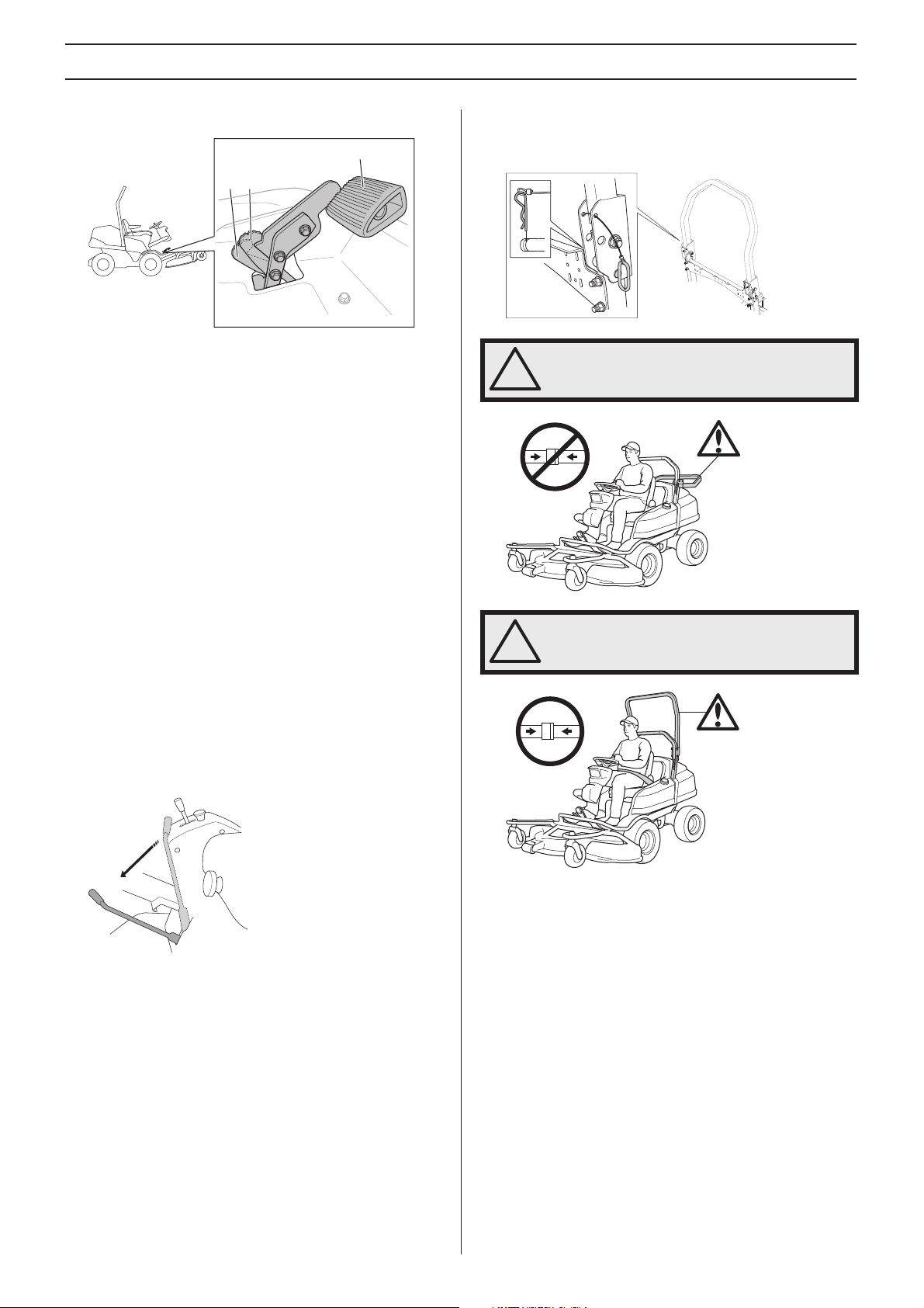
Speed limiter
The speed of the machine is steplessly regulated with two
pedals. Pedal (1) is used to drive forwards, and pedal (2) to
drive backwards.
1
2
–
The machine is braked when the forward pedal is released.
The reverse pedal can also be used if additional braking
power is required.
English
MACHINE´S SAFETY EQUIPMENT
High and low speed catches (P 525D)
3
1
2
8095-306
1 Low speed catch
2 Full speed catch
3 Forward pedal
The forward pedal has a catch that can be foot operated.
Maximum speed is obtained with the catch in high-speed
position (2). Recommended for transport operation.
Control will go into low-speed mode when the catch is pulled
back, which will engage limited speed on the machine (1).
Low-speed mode is preferred for best ergonomics when
working at low speed, mowing for example.
The frame can be folded down.
• Remove the two pins that hold the frame and fold it
backwards.
WARNING! If the frame is folded down the
safety belt should NOT be used.
!
Accelerator check
• Ensure the forward and reverse pedals can be operated
freely.
• Ensure the machine brakes when the forward pedal is
released.
• Ensure the catch returns to high-speed position by lifting
up the forward pedal with your foot.
Parking brake
Operate the parking brake by moving the handle forwards.
Checking the parking brake
Make sure the parking brake is properly adjusted by placing
the machine on a slope.
• Apply the parking brake.
• When the machine does not stand still, the parking brake
should be adjusted.
ROPS (Roll Over Protective Structure)
ROPS is a protective frame that reduces the risk of injury in
the event of overturning. Use ROPS and a safety belt when
driving on slopes.
WARNING! If the frame is folded up, the
safety belt must be used.
!
ROPS check
• Check that the ROPS is securely attached and not
damaged.
Safety belt
The seat belt protects the driver from injury in case of crashes
or overturning.
The belt may only be used when the bar (ROPS) has been
raised or a cab is fitted on the machine.
When the safety belt is not used, it must be wrapped around
the chair back and tightened.
Seat belt check
• Check regularly that the seat belt is intact and secured
correctly.
English – 11
MACHINE´S SAFETY EQUIPMENT
Counter weight
The counterweight must always be used if the machine is
being operated with cab. The counterweight will improve
machine stability.
Checking the counterweight
Check regularly that the counterweight is mounted correctly
and securely in place.
Muffler
The muffler is designed to keep noise levels to a minimum
and to direct exhaust fumes away from the user.
WARNING! Never use a machine without a
muffler, or with a faulty muffler. A damaged
!
muffler may substantially increase the noise
level and the fire hazard. Keep fire fighting
equipment handy.
WARNING! The inside of the muffler contain
chemicals that may be carcinogenic. Avoid
!
contact with these elements in the event of a
damaged muffler.
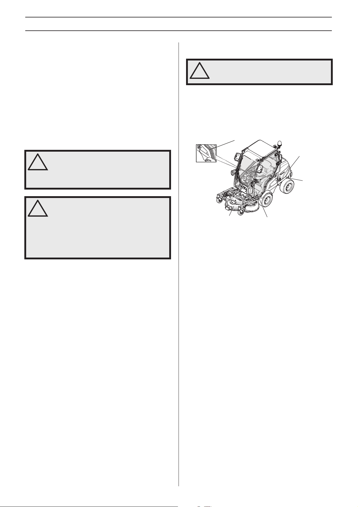
Protective covers
WARNING! Always check that the protection
covers are correctly fitted before starting the
!
machine.
Protective covers on the machine protects the user from the
cooling fan, belt drives and hot surfaces.
Checking the protective covers
• Check the protective covers for cracks or other damages.
Replace damaged covers.
1
2
3
5
4
The muffler gets very hot during and after
use as well as when idling. Be aware of the
fire hazard, especially when working near
flammable substances and/or vapours.
Inspecting the muffler
• Check that the muffler is securely attached and not
damaged.
1 Side cover
2 Engine cover
3 Transmission cover
4 Service hatch
5 Belt covers (3 pcs.)
12 – English
ASSEMBLING AND ADJUSTMENTS
Safety when assembling and settings
WARNING! The engine emits carbon
monoxide, which is a colourless, poisonous
!
gas. Do not use the machine in enclosed
spaces.
• Never leave the machine unsupervised with the engine
running. Always stop the blades, apply the parking brake,
stop the engine and remove the keys before leaving the
machine.
• Never allow children or other persons not trained in the
use of the machine to use or service it. Local laws may
regulate the age of the user.
• Electrical shocks can cause injuries. Do not touch cables
when the engine is running. Do not test the ignition
system with your fingers.
WARNING! The engine and the exhaust
system become very hot during operation.
!
Risk of burn injuries if touched.
• The machine is tested and approved only with the
equipment originally provided or recommended by the
manufacturer.
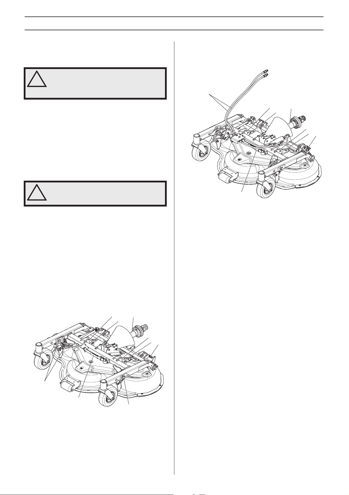
Cutting unit
The machine can be fitted with 4 different cutting decks.
Combi 132 and Combi 155 with 7-step, manual cutting height
adjustment and Combi 132X and Combi 155X with variable,
hydraulic cutting height adjustment.
The Cutting Unit Components
- Combi 132 X, Combi 155 X
The components mentioned are:
6
1
2
5
1 Attachment point
2 Bolt
3 Universal drive shaft
4 Spring-loaded catch for link
5 Service strut
6 Hydraulic hoses
3
1
2
4
The Cutting Unit Components
- Combi 132, Combi 155
The components mentioned are:
1
2
5
6
1 Attachment point
2 Bolt
3 Universal drive shaft
4 Spring-loaded catch for link
5 Cutting height control
6 Service strut
3
1
2
4
5
English – 13
ASSEMBLING AND ADJUSTMENTS
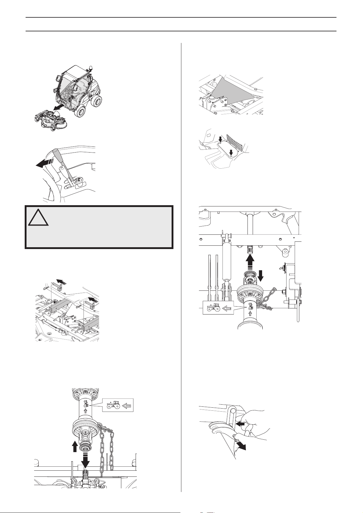
Fitting the cutting head
1 Ride the machine to the cutting deck.
2 Lower the lift arms to the cutting deck attachment points.
WARNING! If the help function is engaged,
the lift arms will move with great force if
!
someone releases the lifting lever. Observe
caution to avoid trapping your hand.
6 Secure the front locking chain to the universal joint cover
around the cross pipe.
7 Make sure the rubber casing is folded over the front
universal joint.
8 Remove the service hatch.
9 For more information, see 'Removing the ride-on mower
covers'.
10 Couple the rear of the propeller shaft to the power take-off
on the machine.
Risk of crush injuries.
3 Activate the parking brake and turn off the engine.
4 Insert the bolts for the link joints and the pins on both sides
of the cutting deck.
5 Fit the universal drive shaft to the cutting unit. The
propeller shaft is marked with an arrow indicating the
direction in which it is to be connected to the power takeoff on the machine. Slide back the ring to release the quick
coupling and the universal drive shaft can be pushed onto
the shaft journal.
11 Fit the locking chain to the universal joint cover around the
lifting beam.
12 Refit the service hatch.
13 Start the engine and lift the cutting unit halfway up.
14 Turn off the motor.
15 Fit the lifting eyes which are attached to the lift arms. Pull
out the catch and press in the lifting eye. There is one for
each lift arm.
14 – English
16 Check and adjust the tilt angle of the cutting unit. For more
information, see 'Cutting Height and Tilt Angle
Adjustment'.
ASSEMBLING AND ADJUSTMENTS
Fitting the cutting head
- Combi 132 X, Combi 155 X
17 Follow the instructions for 'Assembling the Cutting Deck'
steps 1-16.
18 Pull the hydraulic hoses from the cutting deck through the
eyelet.
19 Connect the hydraulic hoses from the cutting deck to the
quick couplings on the machine.
20 Make sure hydraulic hoses are coupled correctly by
adjusting the cutting height with the cutting height control
on the machine. For more information, see 'Cutting Height
- Combi 132 X, Combi 155X'.
3 Raise the cutting unit halfway.
4 Turn off the motor.
5 Remove the lifting eyes from the cutting unit.
6 Start the engine and lower the cutting unit to the lowest
position. The cutting unit now hangs free at the back.
7 Turn off the motor.
8 Remove the service hatch.
21 Select a function with the cutting height control (raise,
lower) with the location of the hydraulic hoses in the quick
couplings on the machine. Switch the raise and lowering
function by changing the location of the hydraulic hoses.
Removing the cutting unit
WARNING! Never leave the universal drive
shaft of the machine with one end loose. If
!
the engine is started, damage can occur.
1 Place the machine on a flat surface and apply the parking
brake.
2 Disconnect the hydraulic hoses from the quick
connections on the machine.
(Combi 132 X, Combi 155 X)
9 Slide back the ring to release the quick connector and to
be able to pull the propeller shaft from the shaft journal.
Remove the universal drive shaft completely. Lift off the
lock chains.
10 Remove the pins from the bolts and remove the bolts from
the link joints.
WARNING! If the help function is connected,
the lift arms move with great force when the
!
pins are loosened. Observe caution to avoid
trapping your hand.
English – 15
ASSEMBLING AND ADJUSTMENTS
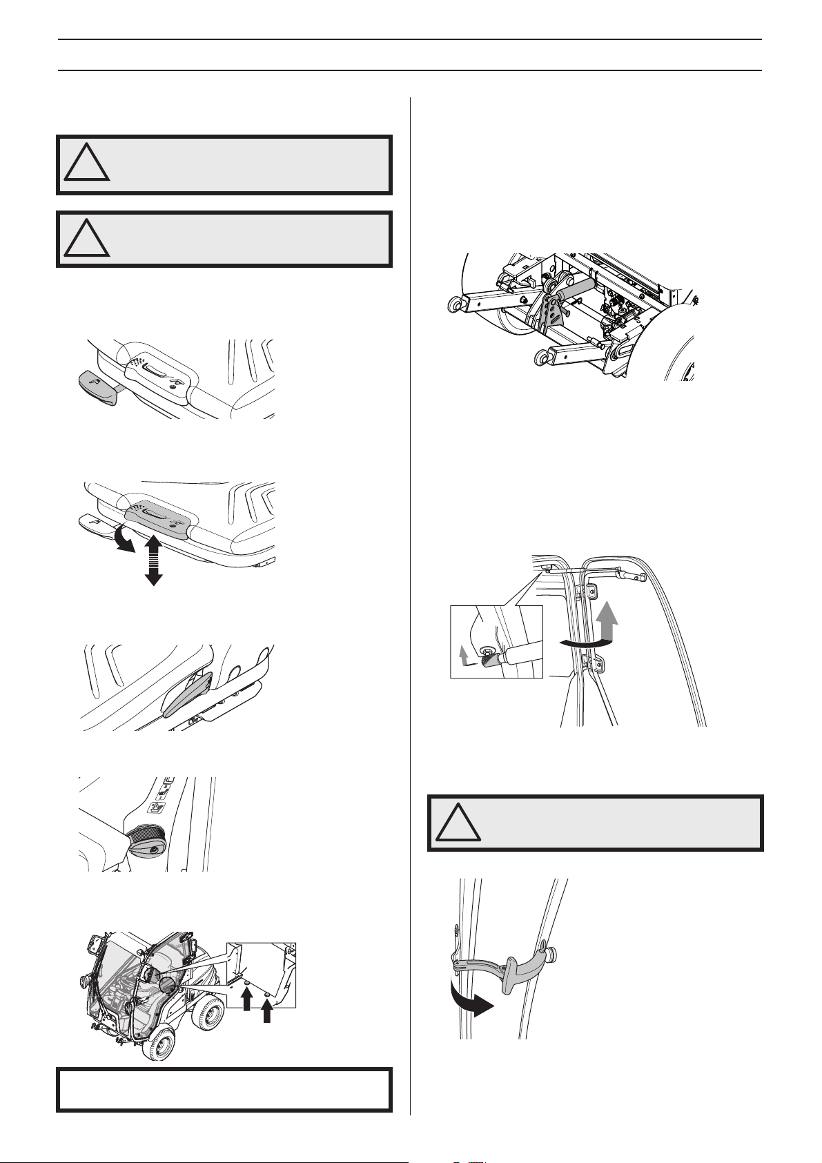
Seat adjustment
WARNING! Take care so that hands are not
trapped or injured by the locking hooks
!
when the seat is folded back.
WARNING! Do not adjust seat settings while
driving. Risk of unsafe manoeuvring.
!
The seat can be adjusted lengthways. When making
adjustments, the lever under the front edge of the seat is
moved up, after which the seat can be moved backwards or
forwards to the desired position.
The seat suspension can be adjusted to driver’s weight. The
weight can be set by extracting the lever in the front of the seat
and pumping up or down.
1
Auxiliary lift system settings
The auxiliary lift system reduces the ground pressure exerted
by the cutting deck pivot wheel and transfers it to the front
wheel of the machine.
The effect of the auxiliary lift system can be adjusted by
moving the gas spring up or down.
• Maximum effect is obtained when the gas spring is placed
in the top hole.
• No effect is obtained in the slot at the bottom.
• When using the cutting unit, the gas spring must be
mounted in the top hole.
Dismantling the doors
1 Opening the driver’s door.
2 Loosen the gas spring by pulling back on the bayonet
mount and loosening the ball joint.
2
Backrest tilt is adjusted with the lever on the right side of the
seat.
Lumbar support is adjusted with the knob on the back of the
seat.
The seat has a jointed attachment on the front edge and can
be tipped forward. The knobs on the back of the seat must be
loosened in order to tilt forward the seat.
3 Open the door 90 degrees.
4 Take a firm grip of the door and lift it straight up.
WARNING! Handle the door with great care!
!
5 Open the emergency exit with the handle inside the cab.
IMPORTANT! When the seat is folded back theknobs and
the washers
16 – English
must be fitted properly in place
6 Open the door 90 degrees.
7 Take a firm grip of the door and lift it straight up.
Assemble the parts in the reverse order.
ASSEMBLING AND ADJUSTMENTS
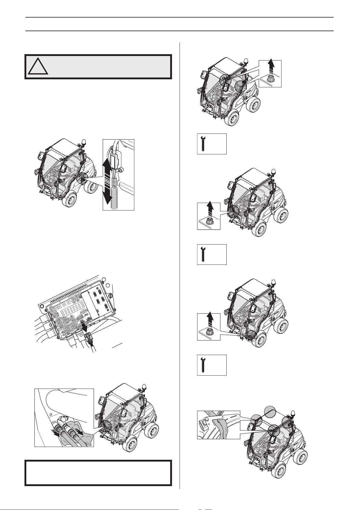
Dismantling the cab
WARNING! ROPS must be fitted if the
machine is used without cab.
!
1 Dismantle the doors. For more information, see
“Dismantling the doors'.
2 Open the engine cover. For more information, see
'Removing the ride-on mower covers'.
3 Disconnect the electricity between the cab and the battery
by unplugging the contact between the cab and the
battery.
4 Dismantle the side cover. For more information, see
'Removing the ride-on mower covers'.
5 Dismantle the protective cover by unscrewing the 4
screws.
6 Loosen the cable harness from its attachment on the fuse
box.
7 Unplug the connection.
10 Remove the screw and washer from both sides behind the
seat.
19mm
11 Remove the screw and washer behind the heater hoses.
17mm
12 Remove the screw and washer at the driver’s door.
8 There is a loose rubber grommet in the fuse box. Fit the
rubber grommet into the empty slot.
9 Uncouple the heater hoses.
CAUTION! Coolant may leak from the hoses when
uncoupled. Place a rag under the hoses to prevent the fluid
from running out into the cab.
17mm
13 Fold forward the seat.
14 Attachments for the front work lighting also act as the cab
lifting points.
English – 17

ASSEMBLING AND ADJUSTMENTS
15 Fasten the lifting straps to the lifting points.
16 Attach another lifting strap through the rear part of the
cab.
17 Use the lifting straps to carefully lift the cab a few
centimeters. The cab should now be hanging freely a few
centimeters above the machine.
CAUTION! Make sure the studs are not damaged.
18 Slide the cab forwards in the machine’s direction of travel
to release it from the machine.
19 Lift of the cab.
20 Place the cab as instructed in “Transport and storage".
21 Assemble the ROPS (Roll Over Protective Structure) See
“Assembling the ROPS (Roll Over Protective Structure)"
for more information.
Assemble the parts in the reverse order.
CAUTION! Take great care not to pinch the cables when
assembling the cab.
Assembling the ROPS (Roll Over
Lowering the ROPS (Roll Over Protective Structure) - Accessories
1 Remove the pin.
2 Lower the bar over the engine cover.
3 Fasten the pin in the middle hole.
Protective Structure) - Accessories
1 Lift up the bar and place it over the steel attachments
behind the seat.
2 Fasten the bolts in the top hole.
3 Tighten the bolt correctly. The bolt should be tightened
with a torque of 47 Nm.
4 Fit the pin into the bottom hole.
18 – English

FUEL HANDLING
General
WARNING! Running an engine in a confined
or badly ventilated area can result in death
!
due to asphyxiation or carbon monoxide
poisoning. Do not use the machine in
enclosed spaces.
Fuel and fuel fumes are flammable and can
cause serious injury when inhaled or
allowed to come in contact with the skin. For
this reason observe caution when handling
fuel and make sure there is adequate
ventilation.
The exhaust fumes from the engine are hot
and may contain sparks which can start a
fire. Never start the machine indoors or near
combustible material!
Do not smoke and do not place any hot
objects in the vicinity of fuel.
Fuel
• Top up with diesel fuel. Gasoline may not be used under
any circumstances.
• Use fuel with a cetane rating over 45. Max RME mixing
5% in mineral oil-based fuels.
Winter fuel
When driving in very cold weather operating problems due to
paraffin precipitation can occur if you run on standard fuel. To
counteract this, winter fuel is sold in the climate areas
affected. In some regions, different fuel is sold in summer and
winter. Ask your fuel supplier and use only winter fuel below
0
°C (+32°F).
Fueling
WARNING! Diesel is highly flammable.
Exercise care and refuel outdoors.
!
Clean the area around the fuel cap.
Tighten the fuel cap carefully after refuelling.
If the cap is not properly tightened the cap
might vibrate lose and fuel may escape from
the fuel tank creating a fire hazard.
Move the machine at least 3 m from the
refuelling point before starting it.
The fuel level in the tank is shown by the gauge on top of the
tank.
The diesel engine injection system is very sensitive and can
be damaged by the slightest contamination. Observe the
greatest possible fuel cleanliness. Use only clean containers.
• Clean the area around the fuel cap. Contamination in the
tank can cause operating problems.
• When refuelling, open the fuel cap slowly so that any
excess pressure is released gently.
• Wipe up any spillage. Materials contaminated by fuel must
be moved to a safe location.
• Handle oil, oil filters, fuel and the battery carefully, of
environmental considerations. Follow the local recycling
requirements.
Never start the machine:
• If you have spilled fuel on yourself or your clothes, change
your clothes. Wash any part of your body that has come in
contact with fuel. Use soap and water.
• If you have spilled fuel or engine oil on the machine. Wipe
off the spill and allow the remaining fuel to evaporate.
• If the machine is leaking fuel. Check regularly for leaks
from the fuel cap and fuel lines.
• Unless the fuel cap is securely tightened after refueling.
Transport and storage
• Store and transport the machine and fuel so that there is
no risk of any leakage or fumes coming into contact with
sparks or open flames, for example, from electrical
machinery, electric motors, electrical relays/switches or
boilers.
• When storing and transporting fuel always use approved
containers intended for this purpose.
• Store the machine and fuel in such a way that there is no
risk that leaking fuel or fumes can cause any damage.
Fuel which is left to stand for long periods (30 days or more)
can leave sticky deposits and interfere with the engine
function. Fuel stabiliser is an acceptable alternative to avoid
tacky deposits during storage.
• Add stabiliser to the fuel in the tank or the storage
container.
• Always use the mixing ratios indicated by the
manufacturer.
• Run the engine for at least 10 minutes after adding the
stabiliser.
• Allow the engine to cool before refuelling.
• Check the fuel level before each use and leave space for
the fuel to expand, because the heat from the engine and
the sun may otherwise cause the fuel to expand and
overflow.
WARNING! Never store a machine with fuel
in the tank indoors or in poorly ventilated
!
spaces where fuel vapour can come in
contact with open flames, sparks, or a pilot
light such as in a boiler, hot water tank,
clothes drier, etc.
Exercise caution when handling fuel. It is
highly inflammable, and careless use can
cause serious injury and damage to
property.
English – 19

OPERATING
General safety precautions
• Read all the instructions in this operator’s manual and on
the machine before you start it. Ensure you understand
them and then observe them.
WARNING! This machine produces an
electromagnetic field during operation. This
!
field may under some circumstances
interfere with active or passive medical
implants. To reduce the risk of serious or
fatal injury, we recommend persons with
medical implants to consult their physician
and the medical implant manufacturer
before operating this machine.
• Serious accidents may occur if you fail to be on your guard
for children in the vicinity of the machine. Children are
often attracted to the machine and mowing. Never
assume that children will remain where you last saw them.
• Keep an eye out and shut off the machine if children enter
the work area.
• Remember that the driver is responsible for dangers or
accidents.
WARNING! This machine can sever hands
and feet as well as throw objects. Failure to
!
observe the safety instructions can result in
serious injuries.
• Learn how to use the machine and its controls safely and
learn to how to stop quickly. Also learn to recognize the
safety decals.
• Only allow the machine to be used by adults who are
familiar with its use. Never allow children to operate the
machine.
• Never carry passengers. The machine is only intended to
be used by one person.
Personal protective equipment
WARNING! You must use approved personal
protective equipment whenever you use the
!
machine. Personal protective equipment
cannot eliminate the risk of injury but it will
reduce the degree of injury if an accident
does happen. Ask your dealer for help in
choosing the right equipment.
• Use hearing protection to minimise the risk of hearing
impairment.
• Never wear loose-fitting clothing, jewellery or similar that
can get caught in moving parts.
• Never use the machine when barefoot. Always wear
protective shoes or protective boots, preferably with steel
toes.
20 – English
Other protective equipment
• Make sure that you have first aid equipment close at hand
when using the machine.
• Fire Extinguisher

OPERATING
Work safety
• Make sure nobody else is in the vicinity of the machine
when you start the engine, engage the drive or drive off.
• Clear the area of objects such as stones, toys, wires, etc.
that may become caught in the blades and be thrown out.
• Look out for the ejector and do not direct it towards
anyone.
• Always look downwards and backwards before and while
reversing. Keep watch for both large and small obstacles.
• Slow before cornering.
• Switch off the blades when you are not mowing.
• Take care when rounding a fixed object, so that the blades
do not hit it. Never run the machine over foreign objects.
• Only use the machine in daylight or in other well-lit
conditions. Keep the machine at a safe distance from
holes or other irregularities in the ground. Pay attention to
other possible risks.
• Never use the machine if you are tired, if you have
consumed alcohol, if you are taking other drugs or
medication that can affect your vision, judgement or coordination.
• Never use the machine in bad weather, for instance in fog,
in rain, damp or in wet locations,strong winds, intense
cold, risk of lightning, etc.
• Keep an eye on the traffic when working close to a road or
when crossing it.
Driving the Rider
WARNING! Make sure that branches do not
obstruct the pedals when mowing under
!
bushes.
Localise and mark stones and other fixed
objects to avoid collision.
• Release the parking brake before driving
• When driving the throttle control must be in the position for
maximum engine speed, work mode.
• Carefully press down one of the pedals until the required
speed is obtained. Pedal (1) is used to drive forwards, and
pedal (2) to drive backwards.
1
2
Instrument panel
The indicator lights are on the steering console under the
steering wheel.
123456
7
1 Temperature gauge for coolant *
2 Oil pressure, check oil level and top up if necessary.
3 Indicates glow plug heating
4 Charge the battery.
5 Controls for driving the cutting unit blades activated
6 The parking brake is applied.
7 Spotlight activated
* Temperature gauge for coolant. The engine is liquid cooled.
If overheating of the engine is indicated the first action to take
is to reduce the engine temperature by running the engine at
idle with no load. Turn off the power transmission Check
coolant level and top up if necessary. Also check that the
radiator grill and radiator are clean and not clogged. The grill
is at the rear of the machine and on top of the bonnet.
(P 525D)
The forward pedal has a catch that can be foot operated.
Maximum speed is obtained with the catch in high-speed
position (2). When a steady lower speed is required, the catch
for the forward pedal can be pulled back with your foot. For
more information, please see 'Speed Control'.
3
1
2
8095-306
WARNING! Do not use the Rider on ground
that slopes more than 10
!
upwards and downwards, never across.
Avoid sudden changes in direction.
°. Mow slopes
English – 21

OPERATING
Adjusting the cutting height
The cutting height can be adjusted to seven different
positions.
Select the required cutting height (1-7) using the cutting
height adjusters. Set the knobs horizontally so that they do
not snag on bushes and the like. For more information, see
'Cutting Height and Tilt Angle Adjustment'.
Lever for hydraulic lift of attachments
The lifting lever is used to put the cutting unit in either the
transport or mowing position when hydraulic pressure is
available.
The lever has four different positions.
4
1
2
3
Function button for accessories with extra hydraulics
This button has varying functions depending on the attached
accessory. The button works only with accessories with extra
hydraulic functions. See the operator’s manual for the
accessory in question for more information.
Transport position
• Stop the blades by pressing in the control for driving the
cutting unit.
1 Neutral position or transport position
2 Lowers the cutting unit with spring return to the neutral
position
3 Floating where the lever stops. The unit is lowered to the
automatically floating position, which means that the
cutting unit follows the contours of the ground.
4 Raises the cutting unit with spring return to neutral
position.
Mowing Position
• Lower the cutting unit by directly moving the lever forward
to the float position where the lever stays put. (3)
• Start the drive for the blades by pulling up the drive control
for the cutting unit.
• Pull back on the lever for the hydraulic lift to engage
transport position. The unit is then raised. (1)
Braking
• Release the drive pedals. The machine slows and is
stopped by the drive system. Do not use the parking brake
as the drive brake.
• Quicker braking is possible if you press down the drive
pedal for the opposite direction.
Driving on slopes
Driving on slopes is one of the operations where the risk of
the driver losing control of the machine or of it overturning is
the greatest; this can result in serious injury or death. All
slopes demand extra care. If you cannot reverse up a slope or
if you feel unsure, do not mow it.
IMPORTANT! Do not drive down slopes with the cutting
deck raised.
22 – English
This is what you do
• Remove obstacles such as stones, branches, etc.

OPERATING
• Mow upwards and downwards, not sideways.
• Do not use the machine on ground that slopes more than
10
°.
• Take extra care if any attachments are fitted that can
change the stability of the machine.
• Avoid starting or stopping on a slope. If the tyres start to
slip, stop the blades and drive slowly down the slope.
• Always drive smoothly and slowly on slopes.
• Always use ROPS (Rollover Protective Structure) and
seat belts when riding on slopes.
Lights and power outlet
The lights are switched on and off using the switch on the
instrument panel.
A seat heater or mobile phone charger are examples of
articles that can be connected to the power socket.
The power outlet is switched on and off using power switch on
the control panel.
• Do not make any sudden changes in speed or direction.
• Avoid unnecessary turns on slopes, if necessary, turn
slowly and gradually downwards if possible. Drive slowly.
Do not turn the wheel sharply.
• Watch out for and avoid driving over furrows, holes and
bumps. It is easier for the machine to overturn on uneven
ground. Tall grass can hide obstacles.
• Do not mow too close to edges, ditches or banks. The
machine can suddenly overturn if one wheel comes over
the edge of a steep slope or a ditch, or if an edge gives
way.
• Do not mow wet grass. It is slippery, and tyres can lose
their grip so that the machine skids.
• Do not try to stabilize the machine by putting your foot on
the ground.
• When cleaning the chassis, the machine may never be
driven near verges or ditches.
• When mowing, keep away from bushes and other objects.
• Follow the manufacturer’s recommendations regarding
wheel weights or counterbalance weights to increase
machine stability.
IMPORTANT! Some combinations of accessories require
additional counterweight at the rear Check with your dealer
for the right combination.
The power outlet works even if the ignition is turned off. Do
not forget to disconnect the power outlet or remove the power
consumer when the machine is not in use.
The voltage is 12 V.
Controls - Cabin
1
1 Window wiper with washer
2 Work light - rear
3 Rotating warning light
4 Inner light
23
4
CAUTION! The inner light can be lit without the ignition of
the machine is switched on this makes the battery
discharges faster. Remember to switch off the lights in the
cabin when leaving the machine.
The interior lighting is turned on and off by pressing the
respective end of the lamp.
English – 23

OPERATING
CLOSE
CLOSE
Controls - Control panel
1
2
P
3
5
1 Low beam
2 Parking lights
3 Horn
4 Turning lights
5 Hazard flashers
4
Low beam
The front work lighting and the low beam is connected so that
only one type of lighting is lit at a time.
If the working lights are lit and the low beam is activated the
working lights will automatically switch off. If the low beam is
deactivated the work lights will lit up again.
Turning lights
The turning lights only flashes during a short period of time.
To extend the flashing the turning lights must be reactivated.
Deactivate the turning lights manually by pressing the button
again.
Heating and fan system
Airflow can be adjusted using the knob on the top part of the
fan system.
0 - Off
1 - Minimum flow
2 - Medium flow
3 - Maximum flow
Air circulation in the cab is adjusted with the damper on the
bottom part of the fan system.
1
2
1 Recirculation damper - open
2 Recirculation damper - closed
In order to achieve optimal heat output at low temperature
(under 0°C), the fresh air intake should be blocked and the
damper kept fully open. See “Changing the fan system inlet
filter" for more information.
Transport and storage
IMPORTANT! The parking brake is not sufficient to lock the
machine during transport. Ensure you secure the machine
firmly to the transporting vehicle.
The machine is equipped with a heating system that enables
the temperature in the cab to be adjusted.
Heat is adjusted with the knob on the heater hoses in the cab.
ON
OFF
The fan system is for heating in the cab and to defrost the
window.
• The machine is heavy and can cause serious crush
injuries. Take extra care when loading it onto or off a
vehicle or trailer.
• Use an approved trailer to transport the machine.
• Check and observe local road traffic regulations before
transporting or driving the machine on roads.
To secure the machine on the trailer, two approved tension
belts and four wedge shaped wheel blocks should be used.
• Engage the parking brake and tie the tension belts around
the front and rear brackets.
• Secure the machine by tensioning the belts towards the
back and the front of the trailer respectively.
• Place the wheel blocks in front of and behind the rear
wheels.
24 – English

OPERATING
Transportation and storage of the cabin
WARNING! Handle the cab with great care!
!
• The cab is heavy and can cause serious crush injuries.
Take extra care while dismantling and assembling the cab.
• Keep the cab safe and protected from unauthorized
access. Make sure it is standing securely a cannot tip
over.
• Store the equipment in a lockable area so that it is out of
reach of children and unauthorized persons.
• Stabilize the cab with supports to protect against damage.
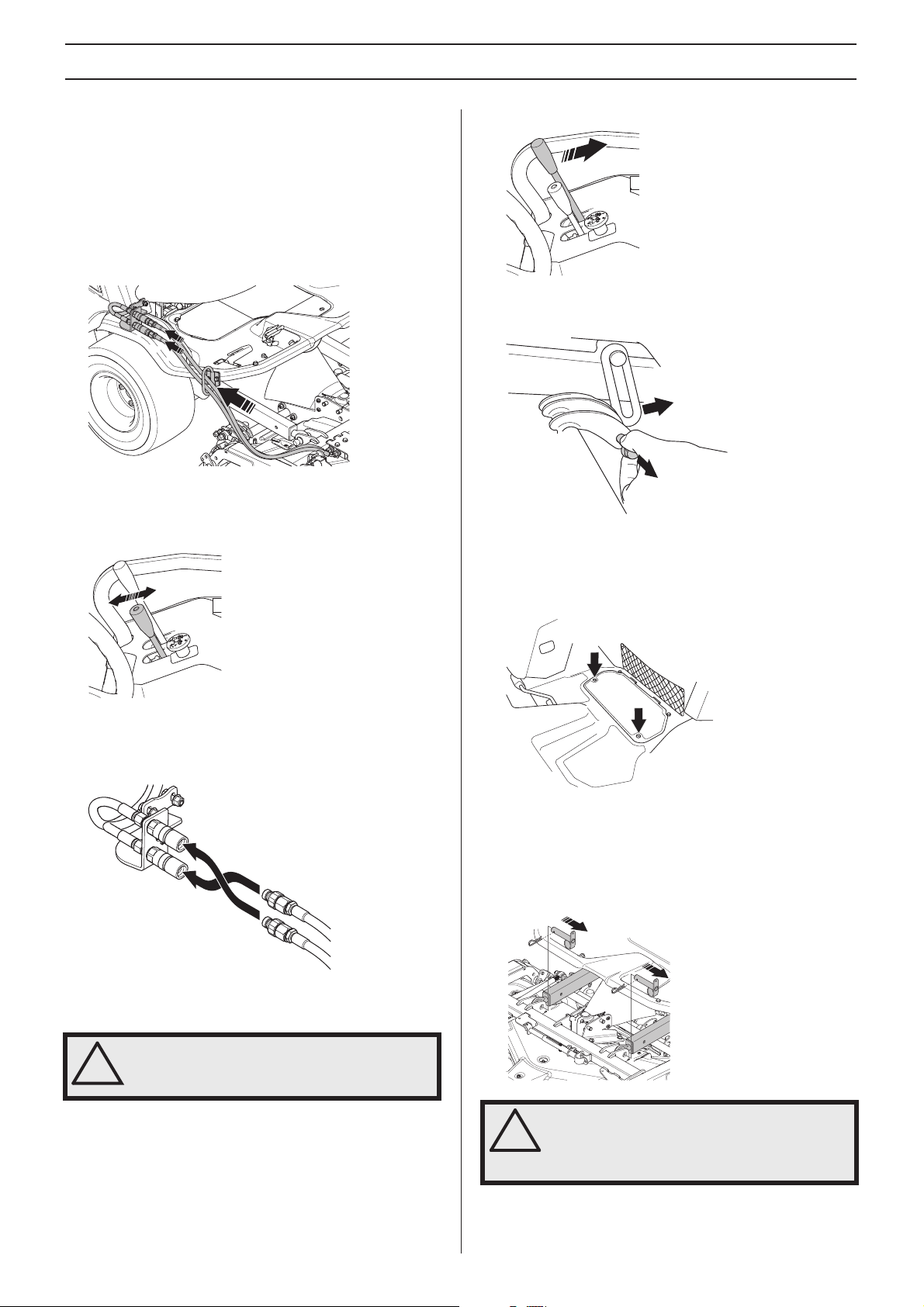
Bypass valves
If you try to drive the machine without hydraulic pressure, it
will not move. The drive on the axle is disengaged if one valve
is open.
The P 520D and the P 525D has two valves, one valve for the
front axle and one for the rear axle.
Bypass valve rear axle
• The hydraulic pressure is released by opening the locking
nut (1) 1/4-1/2 turn anti-clockwise, then the bypass valve
(2) 2 turns.
• The hydraulic pressure is switched on by closing the
valve. Close the valve nut (2) fully before tightening the
locking nut (1).
Bypass valve front axle
Transport with engine off
Hydraulic pressure must be released in order for the ride-on
mower to be moved when the engine is shutoff.
The hydraulic pressure is opened and closed with a bypass
valve.
• The hydraulic pressure is released by opening the locking
nut (1) 1/4-1/2 turn anti-clockwise, then the bypass valve
(2) 2 turns.
• The hydraulic pressure is switched on by closing the
valve. Close the valve nut (2) fully before tightening the
locking nut (1).
Winter storage
At the end of the season, or if the machine is going to stand
idle for more than 30 days, it should immediately be made
ready for storage.
For transport and storage of fuel, see the section "Fuel
handling".
To prepare the machine for storage follow these instructions:
• Carefully clean the machine, especially under the cutting
unit.
• Touch-up paint damage to avoid rust.
• Inspect the machine for worn or damaged parts and
tighten loose screws and nuts.
• Change the engine oil, and take care of the waste oil.
• Fill fuel tank.
• Grease all grease nipples, joints and axles.
• Remove the battery. Clean it, charge it, and store it in a
cool place.
• Store the machine in a clean and dry place and cover it
over for extra protection.
Guard
There is a cover to protect your machine during storage or
transport. Contact your dealer for a demonstration
English – 25

STARTING AND STOPPING
Before starting
• Read the safety instructions and information concerning
the placement of controls and functions before starting.
• Perform daily maintenance before starting as set out in
the Maintenance schedule.
IMPORTANT!
The air intake grille in the engine cover must not be blocked
by, for example, clothing, leaves, grass or dirt. Impaired
cooling of the engine. Risk of major engine damage.
WARNING! Do not modify the machine’s
safety devices and check regularly that they
!
are working properly.
• Localise and mark stones and other fixed objects to avoid
collision.
• Avoid mowing a wet lawn. The mowing results will then be
poorer.
• Start with a high cutting height and reduce down until the
required mowing results are obtained.
• The mowing result will be best with the highest permitted
engine speed, see technical data, (the blades rotate
rapidly) and low speed (the Mower moves slowly). If the
grass is not too high and thick, the driving speed can be
increased without noticeably depreciating the mowing
result.
• The best lawns are achieved if the grass is cut often.
Mowing becomes more uniform and the grass cuttings
become more evenly distributed over the surface. The
total time consumption is not greater since it is possible to
select a higher driving speed without inferior mowing
results.
• When the BioClip function is used, it is very important that
the mowing interval is not too long.
• Hose down the cutting unit with water underneath each
time it is used, avoid using a high pressure washer. The
cutting unit should then be put in the service position.
Start the engine
1 Ensure that the bypass valves are closed.
2 Apply the parking brake.
3 Stop the blades by pressing in the control for driving the
cutting unit.
The engine will not start unless the parking brake is on
and the cutting unit drive activated.
4 Move the throttle control to half throttle.
5 Turn the ignition key to the ignition position and hold it
there until the indicator light on the instrument panel goes
out.
6 Turn the ignition key to the start position.
7 When the engine starts release the ignition key
immediately back to neutral position.
8 Set the required engine speed with the throttle control.
Let the engine run at moderate speed or half throttle for 35 minutes before subjecting it to heavy load.
26 – English
IMPORTANT! Do not run the starter for more than about 15
seconds at a time. If the engine does not start, wait about
15 seconds before trying again.
WARNING! Never run the engine indoors, in
enclosed or poorly ventilated areas. The
!
exhaust fumes contain toxic carbon
monoxide.

STARTING AND STOPPING
Starting when cold
If the engine fails to start due to the cold, repeat ignition and
attempt to re-start. Start gas or ether must not be used.
For more information about winter fuel, please see 'Fuel
handling'.
Half the radiator can be blocked to increase the working
temperature of the engine at low ambient temperatures
(under 0
At temperatures below 0 ° C, the machine must be warmed
up for at least 10 minutes for the hydraulic oil and
transmission to get hot. Otherwise there is a risk of reducing
the service life of the transmission or that the hydraulic
system fails.
°C).
IMPORTANT! At temperatures below 0 ° C, the machine
must be warmed up for at least 10 minutes for the hydraulic
oil and transmission to get hot. Otherwise there is a risk of
the transmission breaking down thereby reducing the
service life of the transmission.
Starting the engine with a weak battery
1 Connect each end of the red cable to the POSITIVE pole
(+) on each battery, exercise care not to short circuit any
of the ends against the chassis.
2 Connect one end of the black cable to the NEGATIVE pole
(-) on the fully charged battery.
3 Connect the other end of the black cable to a good
CHASSIS EARTH, away from the fuel tank and the
battery.
Remove the cables in the reverse order
• The BLACK cable is removed from the chassis and then
the fully charged battery.
• Finally the RED cable from both batteries.
IMPORTANT!
Never use a boost charger/start booster.
Use only conventional battery chargers. Always disconnect
the charger before starting the engine. So called boost
chargers/start boosters must never be used. These will
often increase the voltage (instead of the current) to
generate the power needed to start the engine. This
increase in voltage will damage the electrical system.
WARNING! Lead-acid batteries produce
explosive gases. Avoid sparks, open flames
!
and smoking close to batteries. Always wear
protective glasses in the vicinity of batteries.
If the battery is too weak to start the engine, it should be
recharged.
When jump leads are used for emergency starting, follow the
procedure below:
IMPORTANT! Your Rider is equipped with a 12-volt system
with negative earth. The other vehicle must also have a 12volt system with negative earth. Do not use your Rider
battery to start other vehicles.
Connecting the jump leads
2
1
1
WARNING! Never connect the negative
terminal of the fully-charged battery to, or in
!
the vicinity of, the negative terminal of the
discharged battery. Hydrogen gas may be
present with risk of explosion.
3
English – 27

STARTING AND STOPPING
Braking
WARNING! Never use the reverse pedal to
brake the machine without the cutting unit
!
mounted. Risk of the machine overturning.
Release the drive pedals. The machine slows and is stopped
by the drive system. Do not use the parking brake as the drive
brake.
Quicker braking is possible if you press down the drive pedal
for the opposite direction.
Stop the engine
Always park the machine on a level surface with the engine
OFF.
Preferably allow the engine to idle for a minute to obtain
normal working temperature before stopping it if it has been
working hard.
1 Stop the blades by pressing in the control for driving the
cutting unit.
5 Turn the ignition key to ”OFF”-position.
2 Apply the parking brake by moving the handle downward.
3 Lift the cutting unit with the hydraulic lifting lever.
4 Move the throttle control to the MIN. position.
28 – English

MAINTENANCE AND SERVICE
Maintenance schedule
WARNING! No service procedures must be conducted on the engine or cutting unit unless:
The engine is switched off.
!
The parking brake is applied.
The ignition key is removed.
The following is a list of the maintenance which should be conducted on the machine. For those points not described in this manual,
visit an authorised service workshop.
Daily maintenance Maintenance interval in hours
Maintenance
Check the safety system X
Check for fuel and oil leakage. O
Check the engine’s oil level X X
Check coolant level and antifreeze. X X
Checking the transmission oil level X X
Check and clean the engine’s cooling air intake, clean the radiator. X X
Cleaning X
Clean and lubricate the splines in the wheel hub. O
Start engine and blades, listen for noise O
Check nuts and screws O
Clean underside of cutting unit X
Lubricate throttle cable X
Grease the blade shafts X
Check air filter X
Check the tyre pressures. X
Lubricate according to lubrication schedule, see under heading
"LUBRICATION"
Clean thoroughly around engine X
Clean thoroughly around transmission X
Clean the air filter and empty the particle collector X
Checking the blades X
Replace the fuel filter. X
Change engine oil and filter
Check the synchronisation between the front and rear wheels. O
Change hydraulic oil4) and hydraulic filter
Check oil level in the bevel gear, top up if necessary. X
Check belt tension and condition (alternator belt, PTO belt, cutting
unit belt)
Check the battery condition, clean as necessary. X
Check the wheel nuts. O
Check the parking brake X
Replace the air filter2). X
Change belts (PTO belt and cutting unit belt). X
Change the oil in the bevel gear. X
Change pump and alternator belt X
Change coolant (50% glycol). X
Service at an authorised service representative. O
1)
First change after 25 hours. When operating with a heavy load or at high ambient temperatures, replace every 50 hours.
Maintenance and replacement are required more often in dusty conditions. 3)First change after 25 hours. 4)Conducted by
authorised service workshop.
X = Described in this operator's manual
O = Not described in this operator's manual
1)
3,4)
. O
Before
starting
After work is
completed
10 40 100 200 400 800
X X
X
X
2)
IMPORTANT! When the machine is in operation the hoses are under high pressure. Do not try to connect or disconnect the hoses
when the hydraulic system is operational. This can result in serious personal injuries.
English – 29

MAINTENANCE AND SERVICE
General
Service
Low season is the most suitable time to perform a service or
overhaul of the machine in order to ensure high function
safety during high season.
When ordering spare parts state your machine’s purchase
year, model, type, and serial number.
Always use genuine parts.
An annual check-up by an authorised servicing dealer is a
good way to ensure that your ride-on mower performs at its
best the following season.
Cleaning
Clean the machine directly after use. It is much easier to wash
off grass cuttings before they dry.
Cleaning the radiator cell package
Clean the radiator with compressed air. Use compressed air
blown from the engine compartment through the cell package
and back.
• Open the engine cover.
• If necessary, remove the engine cover. For more
information, see 'Removing the ride-on mower covers'.
Cleaning the air filter
If the engine seems to lack power or does not run smoothly
this may be because the air filter is clogged. When driving
with a dirty air filter the engine can suffer from lack of air, so
that it does not meet environmental requirements and the
engine does not provide full power.
Emptying the particle collector
• Squeeze so that the rubber tabs open and the particles
can escape.
Oily dirt can be removed using a cold degreasing agent.
Spray on a thin layer.
Rinse at normal water pressure.
Do not direct the jet towards electrical components or
bearings.
Do not rinse hot surfaces such as the engine and exhaust
system.
It is recommended that you start the engine and run the
mower for a short period after cleaning, so that any remaining
water is blown off.
Lubricate the machine if necessary after cleaning. Carry out
extra lubrication when the bearings have been exposed to a
degreaser or a water jet.
IMPORTANT! Avoid using a high pressure washer or a
steam cleaner.
There is a major risk of water penetrating into bearings and
electrical connections. Corrosion attack can result, which
will lead to running problems. Cleaning additives generally
aggravate the damage.
Checking the engine’s cooling air intake
• Make sure the radiator grille is free of leaves, grass and
dirt.
Cleaning the filter cover
• Loosen the two fasteners holding the filter cover and
remove it.
• Clean the inside of the lid. It can be washed with soapy
water and blown with compressed air when the lid is
removed.
• Replace the air filter cover, ensure that the particle
collector is facing downwards.
30 – English

MAINTENANCE AND SERVICE
Cleaning the engine and muffler
Keep the engine and muffler free from grass cuttings and dirt.
Clipping debris soaked in fuel or oil on the engine means
increased risk of fire and impaired cooling.
Allow the engine to cool before cleaning. If the dirt is mixed
with oil, remove it using a degreasing agent otherwise just
water and a brush.
Grass cuttings around the muffler dry quickly and constitute a
fire risk. Brush or wash them off when the muffler is cold.
Removing of the machine hoods
WARNING! Always check that the guards are
correctly fitted before starting the machine.
!
Engine cover
Cover Plate
• Loosen screws and remove the cover plates.
Transmission cover
• Loosen the screws and remove the transmission cover.
Adjustment of pump and alternator belt
• Loosen the rubber straps on the side of the cover and lift
up the engine cover.
• If necessary the engine cover can be lifted off by removing
the bolts.
Side cover
• Loosen the screws holding the side cover and remove it.
Service hatch
• Loosen the lower mounting screw and upper adjustment
screw a few turns.
• Tension the belt by pulling the alternator along the track. It
must be possible to press the belt in about 1 cm with your
thumb without too much pressure.
• Tighten the adjustment screw securely.
Change pump and alternator belt
• Loosen the lower mounting screw and upper adjustment
screw a few turns.
A service panel is fitted in the base plate.
• Loosen the screws and lift off the panel.
• Take off the old belt and fit the new one.
• Tension the belt by pulling the alternator along the track. It
must be possible to press the belt in about 1 cm with your
thumb without too much pressure.
English – 31

MAINTENANCE AND SERVICE
Adjusting the parking brake
Make sure the parking brake is properly adjusted by placing
the machine on a slope.
Apply and lock the parking brake.
When the machine does not stand still, the parking brake
should be adjusted according to the following.
1 Position the machine on flat ground.
2 Make sure the parking brake is released.
3 Adjust so there is 1 mm play between the outer cable and
the adjuster screw when you pull the outer cable.
Adjust the adjuster screw using the nuts.
4 Tighten the nuts carefully to prevent damaging the
adjuster screw.
5 The parking brake should be checked again after the
adjustment has been made.
WARNING! A poorly adjusted parking brake
can result in reduced braking ability.
!
• Loosen the lamp by holding down the spring lock.
• Insert the new lamp.
• Refit the cables and lamp insert.
Parking lights
• Loosen the cables from the lamp.
• Lift out the bulbs from the insert.
• Insert the new lamp.
• Refit the cables and lamp insert.
Replacing the light bulbs
For information about the bulb type, see Technical Data.
Low beam, parking lights, turning lights
Unscrew the 4 screws holding the lamp insert.
Low beam
Turning lights
• Loosen the cables from the lamp.
• Loosen the lamp from the lamp insert by turning the lamp
counterclockwise.
• Loosen the cables from the lamp.
32 – English
• Insert the new lamp.
• Refit the cables and lamp insert.

MAINTENANCE AND SERVICE
Work light - front
• Loosen the cables from the lamp.
• Loosen the lamp from the lamp insert by turning the lamp
counterclockwise.
Rotating warning light
• Remove the entire connector and change the lamp-
Main fuse
The machine has a high-power safety fuse located in a box on
the top of the battery plus terminal.
Work light - rear
• Remove the entire connector and change the lamp-
Taillights
A feeder fuse for the electrical connection box is located on
the front of the battery box in the engine compartment.
Other fuses are in the electrical connection box behind right
side cover.
A blown fuse is indicated by a burnt connector. Pull the fuse
from the holder when replacing.
The fuse is there to protect the electrical system.
Do not use any other type of fuse when replacing. If it blows
again shortly after replacement, it is due to a short circuit,
which must be fixed before the machine can be put into
operation again.
Fuses - cab
Cab fuses are located on the front of the battery box in the
engine compartment.
• Remove the entire connector and change the lamp-
• Open the engine cover. For more information, see
'Removing the ride-on mower covers'.
• A blown fuse is indicated by a burnt connector. Pull the
fuse from the holder when replacing. Do not use any other
type of fuse when replacing.
English – 33

MAINTENANCE AND SERVICE
The traffic kit fuses are located under the cover for the servo
housing.
1
2
1 Horn - 5 amp.
2 Parking lights - 5 amp.
• The air distributor must be unscrewed in order to obtain
better access to the servo housing. The air distributor is at
the bottom of the window inside the cab. Dismantle by
loosening the 4 screws and lifting off the air distributor.
Service position for the cutting unit
The cutting head can be placed in the service position to
provide easy access for cleaning, repairs and servicing. In the
service position the cutting unit is raised and locked in the
vertical position.
Placing in the service position
1 Position the machine on flat ground. Apply the parking
brake.
2 Raise the cutting unit halfway.
3 Turn off the motor.
WARNING! Never leave the universal drive
shaft of the machine with one end loose. If
!
the engine is started, damage can occur.
• Unscrew the two screws holding the cover on the power
servo housing.
• A blown fuse is indicated by a burnt connector. Pull the
fuse from the holder when replacing. Do not use any other
type of fuse when replacing.
Fuses in cab roof.
1 2 3 4 5
1 Window wiper - 10 Amp.
2 Fan - 10 Amp.
3 Work light - rear - 10 Amp.
4 Low beam - 10 Amp.
5 Work light - front - 10 Amp.
4 Remove the lifting eyes from the cutting unit.
5 Lower the cutting unit to the lowest position. The cutting
unit now hangs free at the back.
6 Remove the universal drive shaft completely. Lift off the
lock chains.
7 Disconnect the hydraulic hoses from the quick
connections on the machine. (Combi 132 X, Combi 155
X)
8 Remove the service strut from the cutting unit.
34 – English
If it is the first time the service strut is removed, remove
the safety strap from the strut and place it in the storage
compartment under the seat.

MAINTENANCE AND SERVICE
9 Fit the service strut to the attachment under the base
plate. The attachment is highlighted in red.
10 Fit the other end of the strut to the cross tube on the
cutting unit. Pull out the pin and move the strut over the
cross tube to the position marked in red.
11 Release the pin so that it locks over the cross tube.
Restoring from service position
1 Remove the safety belt and place it in the storage
compartment.
2 Lower the cutting unit to the lowest position.
3 Remove the service strut and place it on the cutting unit.
12 Start the engine and raise the cutting unit to the service
position.
13 Secure the cutting unit with the safety belt, which is stored
in the storage compartment under the seat.
4 Fit the universal drive shaft to the cutting unit. Secure the
front locking chain to the universal joint cover around the
cross pipe.
5 Start the engine. Raise the cutting unit halfway.
6 Fit the lifting eyes which are attached to the lift arms. Pull
out the catch and press in the lifting eye. There is one for
each lift arm.
7 Lower the cutting unit.
English – 35

MAINTENANCE AND SERVICE
Cutting height and tilt angle adjustment.
When a cutting unit is installed the cutting height and tilt angle
need to be adjusted
The adjustment must be made in the stated order.
Starting position:
1 Check the tyre pressures. The tyre pressure should be 1.5
bar/150 kPa/22 PSI for all wheels
2 Place the machine on a flat surface.
3 The cutting deck must be fully lowered on a level surface.
Cutting height - Combi 132, Combi 155
WARNING! Keep unauthorised persons at a
distance. You are responsible to ensure that
!
animals and onlookers are not within the
working area.
1 Position the machine on flat ground. Apply the parking
brake.
2 Raise the cutting unit halfway.
3 Turn off the motor. Adjust the cutting height by loosening
the handle and selecting the desired cutting height.
Cutting height (1-7) is indicated inside the adjusting plate.
The handle can be placed in different holes depending on
the cutting height. Set the same height on all three control
points.
Tilt angle - Combi 132, Combi 155
• Place the machine on a flat surface.
• Check the tyre pressures. The tyre pressure should be 1.5
bar/150 kPa/22 PSI for all wheels
• Measure the distance between the ground and the front
and rear edges of the cutting unit hood.
• The rear edge of the cutting unit should be 6-9 mm (1/4"3/8") higher than the front of the unit.
• If necessary, loosen the lock nut and turn the adjusting
brace. Extend the brace to raise the rear edge of the
cutting unit.
4 Hand tighten the cutting height adjustment knob.
5 Adjust the control on the cutting unit. Remove the locking
pin and pull the control the required position. Set the same
height on all three control points.
Height intervals are in seven different positions.
Frequency Approximate cutting height mm/in
1 30 / 1,18
2 40 / 1,57
3 52 / 2,04
4 64 / 2,51
5 76 / 2,3
6 93 / 3,66
7 112 / 4,4
• Tighten the lock nut against the ball joint.
Cutting height - Combi 132 X, Combi 155 X
WARNING! Keep unauthorised persons at a
distance. You are responsible to ensure that
!
animals and onlookers are not within the
working area.
1 Position the machine on flat ground. Apply the parking
brake.
2 Adjust the cutting unit to the lowest cutting height and
lower the cutting unit.
3 Adjust the cutting height by moving the lever forwards or
backwards. The height adjustment is variable.
36 – English

MAINTENANCE AND SERVICE
4 The selected cutting height is indicated on the cutting
deck.
The adjustment bar raise and lower function depends on the
location of the hydraulic hoses in the quick couplings on the
machine.
• Test adjustment bar function by depressing the button on
the bar and moving it backwards and forwards.
• Switch the raise and lowering function by changing the
location of the hydraulic hoses.
Tilt angle - Combi 132 X, Combi 155 X
• If necessary, loosen the lock nut and turn the adjustment
screw on both sides of the cutting deck. Extend the stay in
order to raise the front edge of the cutting deck.
• Tighten the lock nut against the ball joint.
Replacing the cutting unit belts
WARNING! Protect your hands with gloves.
There is a risk of crush injuries when
!
working with the belt.
On these cutting units with collision-proof blades, the blades
are driven by one V-belt. Do as follows to change the V-belt:
1 Remove the screws holding the belt covers and lift them
off.
2 Use the service strut to relieve the spring and release the
belt tension.
• Place the machine on a flat surface.
• Check the air pressure in the tyres The tyre pressure
should be 1.5 bar/150 kPa/22 PSI for all wheels
• Measure the distance from the front and back edge on
both sides of the deck to the ground.
• The rear edge of the cutting unit should be 6-9 mm (1/4"3/8") higher than the front of the unit.
3 Prise the belt off the pulleys.
4 Fit the belt around the pulleys. The belt tightening
schedule is on a decal located on the cutting unit under
the belt cover.
5 Fit covers.
English – 37

MAINTENANCE AND SERVICE
Checking the blades
To achieve the best mowing results it is important that the
blades are undamaged and well-sharpened.
Check that the blades’ attachment screws are tight. Screws
should be torque tightened to 84 Nm.
IMPORTANT! One or more unbalanced blades , caused by
damage or poor balancing after sharpening, can cause
vibrations in the machine.
The blades should be balanced after sharpening.
Damaged blades should be replaced when hitting obstacles
that result in a breakdown.
Replacing the blades
• Put the unit in the service position, see Placing in the
service position.
• Remove the equipment frame.
• Lock the blade with a wooden block. Loosen the blade bolt
and remove the blade bolt, the washers and the blade.
IMPORTANT! Always exercise care and use your common
sense. Avoid all situations which you consider to be beyond
your capability. If you still feel uncertain about operating
procedures after reading these instructions, you should
consult an expert before continuing. Contact an authorised
service workshop.
Always use genuine parts. For more information, see the
”Technical data” section.
Removing the BioClip plug
To change a Combi unit from BioClip function to cutting unit
with rear ejection, remove the BioClip plug located under the
unit with three screws.
1 Put the unit in the service position, see Placing in the
service position.
2 Remove the three screws holding the BioClip plug, and
remove the plug.
• Assemble the parts in the reverse order.
• The blade must be mounted with the angled ends pointing
up towards the cover.
• Tightening torque 80-84 Nm (8,15-8,56 kpm/59-62 lbft).
18mm
WARNING! Wear gloves to protect your
hands when working with the blades.
!
3 Tip: Fit three full-thread screws M8x15 mm in the screw
holes to protect the threads.
4 Replace the unit in normal position.
Fit the BioClip plug in the reverse order.
Adjustment of PTO belts
1 Tighten screw (4) until the sleeve bottoms against the
frame bracket. Tighten lock nut (3) whilst holding screw (4)
firmly.
38 – English

MAINTENANCE AND SERVICE
Change PTO belts
WARNING! Protect your hands with gloves.
There is a risk of crush injuries when
!
working with the belt.
Always replace the belts in pairs.
1 Prevent the engine from starting by removing the ignition
key before making any adjustments or performing
maintenance.
2 Fold down driver's seat.
3 Remove the cover plate of the hydraulic pump drive shaft.
4 Unscrew the bolts (1) of the coupling that connects the
drive shaft and the hydraulic pump and remove the spacer
ring (2) from the coupling. The drive shaft must be locked
with some kind of tool, for example. a big U-spanner or
screwdriver.
10 Pull the belt onto the pump belt pulley first and then onto
the lower belt pulley. Repeat the procedure with the
second belt.
11 Fit the spacer (6) to the bearing bridge and screw the
bearing bridge tight with the associated screws (5).
Torque 47 Nm.
6
5
12 Replace the spacer ring (2) and screw the hydraulic pump
securely to the drive shaft. Torque for the screws (1) is 47
Nm.
5 Loosen the lock nut (3) and the lower screw (4) until it is
completely free from the belt tensioner.
6
5
6 Remove rear bearing spacer screws (5) and remove the
spacer (6).
7 Cut/pull off the old belts.
8 Pull the new belts through the gap between the spacer
ring and the hydraulic pump.
13 Fit the belt tensioner screw with spring and sleeve.
Tighten screw (4) until the sleeve bottoms against the
frame bracket. Tighten lock nut (3) whilst holding screw (4)
firmly.
14 Check belt tension after the first 25 hours after belt
change.
9 Feed the lower part of the strap between the bearing
bridge and the bracket.
English – 39

MAINTENANCE AND SERVICE
Change coolant
Correct coolant level is important for the cooling system to
function properly. Therefore the coolant level must be
checked regularly.
The coolant should be visible when the filler cap is removed.
Repeated coolant loss normally indicates leakage. The
cooling system should be checked by a professional. It is not
sufficient just to top up with coolant.
If the engine boils, coolant will be lost. Open the radiator cap
and allow the coolant to cool down. Allow the engine cool
before filling.
The cooling system must not be filled with salt water, as this
will cause corrosion damage to the engine.
Replace coolant if it is discoloured or cloudy
The cooling system must then be thoroughly flushed.
Use only glycol-based antifreeze approved to BS 6580:1992
or ASTM D 3306-89 or AS 2108-1977 (indicated on the
packaging).
The antifreeze must be intended for alloy engines.
Your Husqvarna supplier can provide the right type of
antifreeze.
Use antifreeze all year round and even in climates where
there is no risk of frost.
Antifreeze contains additives that protect the engine cooling
system against corrosion
The coolant and antifreeze should be changed at least every
two years.
• Remove the filler cap.
Fill only with antifreeze and water mixed according to the
following table.
Propylene glycol (MPG) Water Freezing point
60 % 40 % -47 °C / -53 °F
50 % 50 % -37 °C / -35 °F
40 % 60 % -25 °C / -13 °F
IMPORTANT! Never add cold coolant to a hot engine. Risk
of comprehensive engine damage.
• Check the coolant when the engine has run for a few
minutes after filling. There may have been air in the
system that has been released.
Inspecting the muffler
WARNING! The muffler gets very hot in use
and remains so for a short time afterwards.
!
Do not touch the muffler if it is hot!
The muffler is designed to keep noise levels to a minimum
and to direct exhaust fumes away from the user.
• Check regularly that the muffler is complete and secured
correctly.
WARNING! Do not open the cap quickly
when the engine is hot without first
!
releasing the pressure by partially opening
the cap. Risk of burns. Wear protective
gloves and goggles.
WARNING! Antifreeze and coolant are
dangerous to health. Keep them in storage
!
in labelled containers and away from
children and animals.
• When emptying loosen the lower hose to the radiator.
40 – English
Checking the tyre pressure
The tyre pressure should be 1.5 bar/150 kPa/22 PSI for all
wheels for best bearing capacity.
IMPORTANT! Different tyre pressures on the front tyres will
result in the blades cutting the grass at different heights.

MAINTENANCE AND SERVICE
Check the battery
WARNING! Lead-acid batteries produce
explosive gases. Avoid sparks, open flames
!
and smoking close to batteries.
Always wear protective glasses in the
vicinity of batteries.
The machine is equipped with a maintenance-free battery.
The battery has a service window showing different colours.
• White = Charge battery
• Green = OK.
• Red = Change battery.
Clean the battery and holder with soap/water solution.
A discarded or replacement battery should be handled as
hazardous waste.
Replacement of fuel filter
P520 D, P525 D has two fuel filters. A pre-filter and main filter.
Replace the fuel filter every 100 hours (at least once per
season) or more often if it is clogged.
The pre-filter is located under the battery box and is replaced
as follows.
Replacing the air filter
WARNING! The exhaust system is hot. Let it
cool before starting to replace the air filter.
!
If the engine seems to lack power or does not run smoothly
this may be because the air filter is clogged. It is therefore
important to replace the air filter at regular intervals (see
Maintenance/Maintenance Schedule for the correct service
interval).
Replace the air filter as follows:
1 Open the engine cover.
2 Loosen the two fasteners holding the filter cover and
remove it.
IMPORTANT!
Never run the engine without the air filter fitted.
Poorly filtered inlet air is a main factor contributing to engine
wear. Replace the air filter according to the service
schedule or more often in dusty conditions
The filters must not be oiled. They must be fitted dry.
3 Remove the filter cartridge from the filter housing.
1 Open the engine cover.
2 Loosen the hose clips
3 Move the hose clips away from the filter. Use a pair of flat
pliers.
4 Pull off the filter from the hose ends.
5 Press the new filter into the ends of the hoses.
6 Push the hose clips back on the filter and tighten.
The main filter has a paper insert that is changed as follows.
1 Open the engine cover.
2 Unscrew the filter cover and remove the paper filter.
4 Wipe clean the interior of the air filter housing. If
necessary, the cleaning cloth should be moistened with
white spirit or fuel. Water or compressed air should not be
used.
5 Clean the filter by knocking it with care against a hard
surface. Do not use compressed air to clean the filter.
Replace the air filter if it is still dirty.
6 Fit a new air filter cartridge with the hole inward and press
it into place.
7 Replace the air filter cover, ensure that the particle
collector is facing downwards.
English – 41

MAINTENANCE AND SERVICE
Changing the fan system inlet filter
1 Loosen the knobs.
2 Pull out the filter holder.
3 Take the filter out of the filter holder and carefully brush it
free from dirt. Change filter if necessary.
The cutting unit bevel gear
Check the oil level
Check the oil level when the cutting deck is in its lowest
position.
• Insert a clean metal rod (approx. Ø3 mm) through the filler
plug. Lower the rod until it reaches the bottom of the gear
housing (approx. 90 mm).
• Pull up the metal rod and read off the oil level. The oil level
must be between 18-22 mm from the end of the rod.
• Fill with transmission fluid SAE 80W/90 as necessary.
CAUTION! Too high an oil level increases the risk of oil
leakage.
Changing the oil
• Empty the bevel gear through the filler plug using a pump
fitted with a plastic tube that extends to the bottom of the
housing.
Alternative: Remove the cutting unit and plastic covers.
Place the cutting unit on its edge and empty the bevel gear
through the plug.
• Fill the bevel gear with 80 ml of transmission fluid SAE
80W/90
Checking the engine’s oil level.
Check the oil level in the engine when the Rider stands
horizontal with the engine switched off. Do not check the oil
with the engine running.
• Open the engine cover.
• Loosen the dipstick, pull it up and wipe it off.
• Now insert the dipstick again, without tightening it.
• Pull the dipstick out again and read the oil level.
The oil level should be between the markings on the dipstick.
• If the level is approaching the ADD mark, top up the oil to
the FULL mark on the dipstick.
The oil filler is on the valve cap.
• Tighten the dipstick correctly before starting the engine.
• Start and run the engine at idling speed for approx. 30
seconds.
• Turn off the motor. Wait 30 seconds and check the oil
level.
• If necessary fill so that the oil comes up to the FULL mark
on the dipstick.
The following oil classes are recommended:
• API Service Class: CH4 or ACEA E5 or higher.
Choose an oil with viscosity according to the temperature
ranges in the figure:
0W
5W 20
10W 30
15W 40
20W 50
20
30
40
-30 -20 -10 0 10 20 30 40 50 C
-22 -4 -14 32 50 68 86 104 122 F
Do not mix different types of oil.
42 – English

MAINTENANCE AND SERVICE
Replacing the engine oil
WARNING! Engine oil can be very hot if it is
drained directly after stopping the engine.
!
Allow the engine to cool somewhat first.
The engine oil should be changed the first time after 25 hours
running time. It should then be changed after every 100 hours
of running time.
1 Open the engine cover.
2 Place a container underneath the engine oil drain plug.
3 Remove the dipstick. Remove the drain plug from the
engine.
4 Let the oil run out into the container.
5 Fit the drain plug and tighten it.
6 Change oil filter if necessary.
7 If necessary fill so that the oil comes up to the FULL mark
on the dipstick.
8 Run the engine warm, then check that there is no leakage
from the oil plug.
9 Check the engine oil level and top up if necessary.
• Start the engine and let it idle for about 3 minutes. Now
stop it and check for signs of leakage.
• Check the engine oil level and top up if necessary.
IMPORTANT! Used engine oil and transmission oil is
hazardous to health and must not be disposed of in the
ground or out of doors.
Replaced filters must be handed in to the workshop or other
allotted place for disposal.
Avoid skin contact; wash with soap and water in case of
spills.
Check the hydraulic system oil level
The oil and filter should be changed by an authorised service
representative, as described in the Workshop Manual.
Work on the system entails particular demands on
cleanliness and the system must be vented before the
machine is used.
• Fold up the seat.
• Remove the filler cap. The level should be 40-60 mm from
the strainer top.
IMPORTANT! Used engine oil, antifreeze etc. is a health
hazard and must not be disposed of on the ground or in
nature; it should always be disposed of at a workshop or
appropriate disposal location. Avoid skin contact; wash with
soap and water in case of spills.
Changing the oil filter
WARNING! Engine oil can be very hot if it is
drained directly after stopping the engine.
!
Allow the engine to cool somewhat first.
The oil filter is located on the right side of the engine.
• Open the engine cover.
• Place a suitable vessel to collect the oil in.
• Turn the old oil filter anti-clockwise to remove. If
necessary, use a filter remover.
• Clean the oil filter bracket.
• Lightly lubricate the rubber seal on the new oil filter using
new oil.
• Fit the oil filter by turning clockwise. Turn by hand until the
rubber seal is seated. Now tighten a further half turn.
• Refill as required with fully synthetic 10W/50 API SM oil or
better
Check the oil level in the transmission gearboxes
• Use the oil dipstick to check that there is oil in the
transmission.
• The oil level should be between the markings on the
dipstick.
• Refill as required with fully synthetic 10W/50 API SM oil or
better
English – 43

Lubrication schedule
QUICK MAINTENANCE GUIDE
Lubrication
First service after 25 hours
X-Variants
SAE 10W 50 API SM = 8L
ANTIFREEZE =
50% Propylene Glycol
TIRE
PRESSURE = Front & Rear 1,5 bar
Legend for the lubrication schedule
Filter replacement
Oil change
Level check
Grease nipple
Oil can
Check belts, condition and belt tension
Belt replacement
3,0L
3,3L
MOTOR OIL SAE 10W 40 API CP
0,9L
Front & Rear
TRANSMISSION OIL 10W 50 API SM SAE 80W/90 = 80cl (3oz)
General
Remove the ignition key to prevent unintentional movements
during lubrication.
When lubricating with an oilcan, it ought to be filled with engine
oil.
When lubricating with grease, unless otherwise stated, grease
503 98 96-01 or another chassis or ball bearing grease offering
good corrosion protection shall be used.
If the machine is used daily it should be lubricated twice a week.
Wipe away excess grease after lubrication.
It is important to avoid getting lubricant on the belts or the drive
surfaces on the belt pulleys. Should this happen, attempt to
clean them with spirits. If the belt continues to slip after cleaning
with spirits, it must be replaced.
Petrol or other petroleum products must not be used to clean
belts.
44 – English

Lubrication
Accessories
Lubrication or other maintenance of optional equipment or
accessories is not described in this manual. This equipment
too, naturally, requires maintenance. See the manuals for the
respective accessories for instructions.
Pivot wheel bearings
4 nipples (sprocket and pivot shaft bearing), lubricate with
grease gun until grease appears.
Universal drive shaft joints
• Remove the service hatch.
• Loosen the two quick connectors on the universal drive
shaft and remove the universal drive shaft.
• The universal drive shaft has two grease nipples, one on
the front hub and one on the rear hub. Lubricate with a
grease gun until the grease is forced out.
Lift cylinder
• Remove the service hatch.
• 2 grease nipples, one on each side. Lubricate with a
grease gun until the grease is forced out.
The drive shaft front support bearing
• Lubricate with a grease gun until the grease is forced out.
• Lubricate the telescopic joint of the universal drive shaft
with grease.
Cutting unit bracket
• Lubricate swivel joints and shafts with oil.
Lift arm rear bearings
• Remove the service hatch. For more information, see
'Removing the ride-on mower covers'.
• 2 grease nipples, one on each side. Lubricate with a
grease gun until the grease is forced out.
The drive shaft rear support bearing
• 2 grease nipples. Lubricate with a grease gun until the
grease is forced out.
Steering cylinder
The steering cylinder has two grease nipples, one on each
end.
• Lubricate with a grease gun until the grease is forced out.
English – 45

Lubrication
Joint bearing
• Lift the machine under the joint bearing. This will allow the
grease to enter into the correct lubricating point in the
bearing. (1)
• Grease the waist section of joint bearing Lubricate with a
grease gun until the grease is forced out. (2)
2
1
Link brace
2 grease nipples, one on each side.
• Lubricate with a grease gun until the grease is forced out.
Lubricating the cables
• Remove the cable´s rubber casing when lubricating.
• Grease both ends of the cables and move the controls to
end stop positions when lubricating.
• Re-attach the rubber covers on the cables after
lubrication.
Cables with sheaths will jam if they are not lubricated
regularly. A jammed cable may cause malfunction, such as
the parking braking being applied. If a cable binds, remove
the cable and hang it vertically. Lubricate it with thin engine oil
until the oil begins to escape from the bottom.
A tip: Fill a small plastic bag with oil and tape it so that it seals
against the casing and allow the cable to hang vertically from
the bag overnight. If you do not succeed in lubricating the
cable, it must be replaced.
Throttle and choke cables, lever bearings
• Remove the right side cover on the lever housing (3
screws) and open the engine cover.
• Lubricate the cables’ free ends with the oilcan, even those
by the engine.
• Move the controls to the end points and lubricate again.
Knobs for setting the cutting height
• Lubricate front and rear knobs with oil.
Driver seat
• Fold up the seat.
• Lubricate the lever for longitudinal adjustment with oil.
• Lubricate the longitudinal adjustment runners with
grease. Pull the seat back and forth and lubricate on both
sides.
• Replace the lever housing’s side cover.
Lubricate the parking brake wire
• Remove the rubber cover and lubricate the cable with oil.
46 – English

Troubleshooting schedule
Problem Cause
There is no fuel in the fuel tank
Air in fuel system
Engine does not start
Starter motor does not turn over the engine
Engine does not run smoothly
Abnormal exhaust smoke
Black smoke
Blue smoke
White smoke
Engine seems to have no power
Engine overheats
Incorrect fuel type
Ignition system inoperative
Serious engine damage
Battery flat
Poor contact affecting the battery terminal cable connections, ignition lock, or
starter
Power take off (PTO) activated
Air in fuel system
Fuse on or near the battery blown (check 2 off)
Start lock broken
Faulty starter motor
The parking brake is not on
Faulty or improperly adjusted parking brake switch
Faulty relief valve
Clogged fuel filter
Air filter clogged
Fuel tank vent blocked
Low feed pressure
Loose fuel pressure line (injector pipe)
Faulty fuel injector
Faulty injection pump
Faulty feed pump
Incorrect fuel type
Serious engine damage
Incorrect amount of fuel from injection pump
Faulty fuel injector
Incorrect timing of fuel injection pump
Air filter clogged
Engine oil level too high
Serious engine damage
Cylinder head gasket damaged
Cylinder head cracked
Engine oil level too high
Air filter clogged
Air in fuel system
Clogged fuel filter
Faulty relief valve
Low feed pressure
Faulty feed pump
Incorrect timing of fuel injection pump
Serious engine damage
Engine overloaded
Coolant level too low
Air intake or cooling flanges blocked
Fan damaged
Too little or no oil in engine
Incorrect radiator cap
Coolant pump drive belt broken
English – 47

Battery does not charge
Machine vibrates
Uneven mowing
Troubleshooting schedule
One or more battery cells faulty
Poor contact on the battery terminal cable connectors
Defective alternator
Alternator belt broken or slipping
Wires to the alternator broken
Defective battery maintenance
Sulphated battery
Blades are loose
Damaged universal joint
Engine is loose
The hydraulic pump is loose
Damaged support bearing for PTO shaft
Bevel gear is loose
The engine is not firing on all cylinders
Pulley loose or worn bearing on cutting unit
One or more blades unbalanced, caused by damage or poor balancing after
sharpening
Blades blunt
Cutting unit skew
Long or wet grass
Grass blockage under hood
Different tyre pressures on right and left sides
Different tyre pressures on pivot wheel
Over-speeding
Engine speed too low
Cutting unit belt slipping
PTO belt slipping
Cutting height too low
48 – English

TECHNICAL DATA
P 520D P 525D
Dimensions
Unladen weight excluding cutting unit, kg/lb 857/1889,3 907/1999,6
Tyre dimensions 18 x 8,5 x 8 20x10x10
Air pressure, rear - front, kPa / bar / PSI 150/1,5/22 150/1,5/22
Engine
Brand / Model Kubota D902 Kubota D1105
Nominal engine output, kW (see note 1) 14,5 @3000 rpm 18,7 @3000 rpm
Displacement, cm3/cu.in 898 / 54.8 1123 / 68.5
Idle speed, rpm 1800 ± 50 1750 ± 50
Max. engine speed, rpm 3300 3200
Fuel, diesel fuel
Tank volume, litres/USqt 25 / 6.6 25 / 6.6
Oil, API class CD or better SAE 10W/40 SAE 10W/40
Oil volume incl. filter 3,3/3,5 3,3/3,5
Oil volume excl. filter, litres/USqt 3,0/3,2 3,0/3,2
Starting Electric starter Electric starter
Electrical system
Type 12 V, negative earthed 12 V, negative earthed
Battery 12 V, 62 Ah 12 V, 62 Ah
Main fuse, A 125 125
Supply fuse circuit board, A 50 50
Lights
Low beam H7 H7
Parking lights W5W W5W
Turning lights PY21W PY21W
Headlights H9 H9
Taillights LED lights LED lights
Rotating warning light LED lights LED lights
Cooling system
Cooling system capacity, l/USqt 3,7/3,9 3,7/3,9
Antifreeze ≥ 50% propylenglykol (MPG) ≥ 50% propylenglykol (MPG)
Hydraulic System
Max. working pressure, bar / psi 120 / 1740 120 / 1740
Max. workflow l/min / USgal/min 12 / 3,17 12 / 3,17
Hydraulic tank capacity, l/USqt 8/8,5 8/8,5
Hydraulic system capacity, l/USqt 13/13,7 13/13,7
Transmission
Brand Kanzaki KTM 23 Kanzaki KTM 23
Oil, class API SM, ACEA A3/B4 SAE 10W/50 Synthetic SAE 10W/50 Synthetic
Oil capacity gearbox front, l/USgal 0,9 / 0.24 0,9 / 0.24
Oil capacity gearbox rear, I/USgal 0,9 / 0.24 0,9 / 0.24
Max. hydraulic pressure, bar/psi 275/3989 275/3989
Drive
Forward speed, km/h. 0-15 0-18,5
Reverse speed, km/h 0-12 0-14
min 45 cetane 2.0-4.5 cSt @ 40°C
0.835-0.855 kg/l sulphur<0.2w%
min 45 cetane 2.0-4.5 cSt @ 40°C
0.835-0.855 kg/l sulphur<0.2w%
Note 1: The power rating of the engine indicated is the average net output (at specified rpm) of a typical production engine for the
engine model measured to SAE standard J1349/ISO1585. Mass production engines may differ from this value. Actual power
output for the engine installed on the final machine will depend on the operating speed, environmental conditions and other values.
English – 49

TECHNICAL DATA
Technical data concerning the cutting unit
Cutting unit Combi 132 Combi 155
Cutting width, cm/inch 132 / 52 155 / 61
Cutting heights, mm/inch 30-112 / 1.18-4.4 30-112 / 1.18-4.4
Weight, kg/lb 138 / 304 155 / 341,7
Bevel gear oil SAE 80W/90, capacity 0.4 l SAE 80W/90, capacity 0.4 l
Cutter
Article number 5861988-10 5441758-10
Blade length, mm/inch 490 / 19,3 563 / 22.2
Technical specifications for sound and vibration levels
P 520D P 525D
Combi 132 Combi 155 Combi 132 Combi 155
Noise emissions (see note 2)
Sound power level, measured dB(A) 104 104 104 104
Sound power level, guaranteed dB(A) 105 104 105 105
Sound levels (see note 3)
Sound pressure level at the operators ear, dB(A) 88 90 88 89
Vibration levels (see note 4)
Vibration level on the steering wheel, m/s
Vibration level in the seat, m/s
2
2
1,7 1,7 1,7 1,7
0,7 0,7 0,7 0,7
Technical data concerning the cutting unit
Cutting unit Combi 132 X Combi 155X
Cutting width, cm/inch 132 / 52 155 / 61
Cutting heights, mm/inch 30-112 / 1.18-4.4 30-112 / 1.18-4.4
Weight, kg/lb 148 / 326 163 / 359
Bevel gear oil SAE 80W/90, capacity 0.4 l SAE 80W/90, capacity 0.4 l
Cutter
Article number 5861988-10 5441758-10
Blade length, mm/inch 490 / 19,3 563 / 22.2
Technical specifications for sound and vibration levels
P 520D P 525D
Combi 132 X Combi 155 X Combi 132 X Combi 155 X
Noise emissions (see note 2)
Sound power level, measured dB(A) 104 104 104 104
Sound power level, guaranteed dB(A) 105 104 105 105
Sound levels (see note 3)
Sound pressure level at the operators ear, dB(A) 88 90 88 89
Vibration levels (see note 4)
Vibration level on the steering wheel, m/s
Vibration level in the seat, m/s
2
2
1,7 1,7 1,7 1,7
0,7 0,7 0,7 0,7
Note 2: Noise emissions in the environment measured as sound power (LWA) in conformity with EC directive 2000/14/EC.
Note 3: Noise pressure level according to ISO 5395. Reported data for noise pressure level has a typical statistical dispersion
(standard deviation) of 1.2 dB(A).
Note 4: Vibration level according to ISO 5395. Reported data for vibration level has a typical statistical dispersion (standard
deviation) of 0.2 m/s2 (steering wheel) and 0.8 m/s2 (seat).
50 – English

Ride-on mower dimensions
TECHNICAL DATA
N
F
C
A
B
P 520D P 525D
A 897 mm 904 mm
B 1110 mm 1139 mm
C 120 mm 145 mm
D 821 mm 828 mm
E 1034 mm 1063 mm
F 1301 mm 1326 mm
G 474 mm 499 mm
H 644 mm 644 mm
I 1060 mm 1060 mm
J 135 mm 160 mm
K 407 mm 407 mm
L 373 mm 373 mm
M 225 mm 250 mm
N 2003 mm 2028 mm
O 29° 36°
P 2077 mm 2077 mm
D
E
G
J
K
H
I
P
L
M
O
English – 51

TECHNICAL DATA
Cabin dimensions
B
A
P 520D P 525D
A 1983 mm 2008 mm
B 2242 mm 2267 mm
C 1251 mm 1251 mm
D 883 mm 883 mm
E 800 mm 800 mm
F 692 mm 692 mm
G 518 mm 518 mm
H 2269 mm 2269 mm
I 29° 36°
C
D
E
I
FG
H
Cabin support dimensions
B
A
C
A 50 mm
B 100 mm
C 800 mm
D 755 mm
E 844 mm
F 880 mm
G 22,5 mm
H (4x) Ø15
I 96 mm
J 515 mm
K 89 mm
L 700 mm
H
G
I
D
E
F
J
L
K
52 – English

TECHNICAL DATA
IMPORTANT! When the service life of this product has been served and it is no longer used it should be returned to the dealer
or to an applicable station for recycling.
IMPORTANT! We reserve the right to change specifications and designs without prior notice so as to implement improvements.
Note that no legal claims are valid on the basis of information in this manual.
Use only genuine parts for repairs. The warranty is not valid if non genuine parts are used.
EC Declaration of Conformity (Applies to Europe only)
Husqvarna AB, SE-561 82 Huskvarna, Sweden, tel.: +46-36-146500, hereby declares that Husqvarna P 520D and P 525D from
2015’s serial numbers and onwards (the year is clearly stated in plain text on the rating plate with subsequent serial number),
complies with the requirements of the COUNCIL’S DIRECTIVE:
of May 17, 2006 ”relating to machinery” 2006/42/EC.
of February 26, 2014 ”relating to electromagnetic compatibility” 2014/30/EU.
of May 8, 2000 ”relating to the noise emissions in the environment” 2000/14/EC.
The following harmonised standards have been applied: EN ISO 12100-2, ISO 5395
Notified body: 0404, SMP Svensk Maskinprovning AB, Box 7035, SE-750 07 Uppsala, has issued reports regarding the
assessment of conformity according to annex VI of the COUNCIL’S DIRECTIVE of May 8, 2000 ”relating to the noise emissions in
the environment” 2000/14/EC.
The certificates have the numbers: 01/901/165 , 01/901/166 ,01/901/243 ,101/901/244
Huskvarna 16 September 2015
Claes Losdal, Development Manager/Garden Products (Authorized representative for Husqvarna AB and responsible for technical
documentation.)
English – 53


Original instructions
´®z+YtT¶6}¨
´®z+YtT¶6}¨
1157845-26
2016-04-29
 Loading...