

Page 1

HP x360 310 G1 PC
Maintenance and Service Guide
IMPORTANT! This document is intended for HP
authorized service providers only.
Page 2

© Copyright 2014 Hewlett-Packard
Development Company, L.P.
Intel and Pentium are trademarks of Intel
Corporation in the U.S. and other countries.
Bluetooth is a trademark owned by its
proprietor and used by Hewlett-Packard
Company under license. Microsoft, Windows,
and Windows 8 are U.S. registered trademarks
of the Microsoft group of companies. SD Logo
is a trademark of its proprietor.
The information contained herein is subject to
change without notice. The only warranties for
HP products and services are set forth in
the express warranty statements
accompanying such products and services.
Nothing herein should be construed as
constituting an additional warranty. HP shall
not be liable for technical or editorial errors or
omissions contained herein.
First Edition: December 2014
Document Part Number: 803404-001
Product notice
This guide describes features that are common
to most models. Some features may not be
available on your computer.
Not all features are available on all editions of
Windows 8. This computer may require
upgraded and/or separately purchased
hardware, drivers, and/or software to take full
advantage of Windows 8 functionality. See
http://www.microsoft.com for details.
This computer may require upgraded and/ or
separately purchased hardware and/or a DVD
drive to install the Windows 7 software and
take full advantage of Windows 7 functionality.
See http://windows.microsoft.com/en-us/
windows7/get-know-windows-7 for details.
Page 3

Safety warning notice
WARNING! To reduce the possibility of heat-related injuries or of overheating the device, do not place
the device directly on your lap or obstruct the device air vents. Use the device only on a hard, flat surface. Do
not allow another hard surface, such as an adjoining optional printer, or a soft surface, such as pillows or
rugs or clothing, to block airflow. Also, do not allow the AC adapter to contact the skin or a soft surface, such
as pillows or rugs or clothing, during operation. The device and the AC adapter comply with the useraccessible surface temperature limits defined by the International Standard for Safety of Information
Technology Equipment (IEC 60950).
iii
Page 4

iv Safety warning notice
Page 5

Table of contents
1 Product description ....................................................................................................................................... 1
2 External component identification ................................................................................................................. 4
Right side ............................................................................................................................................................... 4
Left side ................................................................................................................................................................. 5
Speakers ................................................................................................................................................................ 6
Display ................................................................................................................................................................... 7
Changing your notebook to an entertainment stand ......................................................................... 8
Changing your notebook to a tablet ................................................................................................... 8
Top ......................................................................................................................................................................... 9
TouchPad ............................................................................................................................................. 9
Lights ................................................................................................................................................. 10
Keys ................................................................................................................................................... 11
Service tag and PCID label ................................................................................................................................... 12
Service tag ......................................................................................................................................... 12
PCID label ........................................................................................................................................... 13
3 Illustrated parts catalog .............................................................................................................................. 14
Computer major components ............................................................................................................................. 14
Mass storage devices .......................................................................................................................................... 17
Miscellaneous parts ............................................................................................................................................. 17
Display assembly subcomponents ..................................................................................................................... 18
Sequential part number listing ........................................................................................................................... 19
4 Removal and replacement procedures preliminary requirements .................................................................... 22
Tools required ...................................................................................................................................................... 22
Service considerations ........................................................................................................................................ 22
Plastic parts ....................................................................................................................................... 22
Cables and connectors ...................................................................................................................... 23
Drive handling ................................................................................................................................... 23
Grounding guidelines ........................................................................................................................................... 24
Electrostatic discharge damage ....................................................................................................... 24
Packaging and transporting guidelines ......................................................................... 25
Workstation guidelines ................................................................................ 25
v
Page 6

5 Removal and replacement procedures for Authorized Service Provider parts ................................................... 27
Component replacement procedures ................................................................................................................. 27
Bottom cover ..................................................................................................................................... 28
USB/audio board ............................................................................................................................... 31
WLAN module .................................................................................................................................... 32
Solid-state drive (M.2) ....................................................................................................................... 34
Hard drive .......................................................................................................................................... 36
RTC battery ........................................................................................................................................ 39
Memory module ................................................................................................................................ 41
Power button board .......................................................................................................................... 43
Fan ..................................................................................................................................................... 45
Heat sink ............................................................................................................................................ 46
Battery ............................................................................................................................................... 49
Speakers ............................................................................................................................................ 50
TouchPad button board .................................................................................................................... 51
Display assembly .............................................................................................................................. 53
Power connector cable ...................................................................................................................... 58
System board .................................................................................................................................... 59
Keyboard ........................................................................................................................................... 62
6 Using Setup Utility (BIOS) ............................................................................................................................. 64
Starting Setup Utility (BIOS) ................................................................................................................................ 64
Updating the BIOS ................................................................................................................................................ 64
Determining the BIOS version ........................................................................................................... 64
Downloading a BIOS update .............................................................................................................. 65
Synchronizing a tablet and keyboard (select models only) ............................................................................... 66
7 Using HP PC Hardware Diagnostics (UEFI) ...................................................................................................... 67
Downloading HP PC Hardware Diagnostics (UEFI) to a USB device .................................................................... 67
8 Backing up, restoring, and recovering ........................................................................................................... 69
Creating recovery media and backups ................................................................................................................ 69
Creating HP Recovery media (select models only) ........................................................................... 69
Using Windows tools ........................................................................................................................................... 70
Restore and recovery .......................................................................................................................................... 70
Recovering using HP Recovery Manager .......................................................................................... 71
What you need to know before you get started ............................................................ 71
Using the HP Recovery partition (select models only) .................................................. 72
Using HP Recovery media to recover ............................................................................. 72
Changing the computer boot order ................................................................................ 73
vi
Page 7

Removing the HP Recovery partition (select models only) ........................................... 73
9 Specifications ............................................................................................................................................. 74
Computer specifications ...................................................................................................................................... 74
Hard drive specifications ..................................................................................................................................... 75
10 Statement of memory volatility .................................................................................................................. 76
Nonvolatile memory usage ................................................................................................................................. 78
Questions and answers ....................................................................................................................................... 80
Using HP Sure Start (select models only) ........................................................................................................... 81
11 Power cord set requirements ...................................................................................................................... 82
Requirements for all countries ........................................................................................................................... 82
Requirements for specific countries and regions ............................................................................................... 82
12 Recycling .................................................................................................................................................. 84
Index ............................................................................................................................................................. 85
vii
Page 8

viii
Page 9

1 Product description
Category Description
Product Name HP x360 310 G1 PC
Processor Intel Pentium N3540 processor (2.16 GHz/2.66 GHz, 2 MB L2, 1333 MHz), quad core
Intel Pentium N3530 processor (2.16 GHz/2.58 GHz, 2 MB L2, 1333 MHz), quad core
Intel Celeron N2840 processor (2.16 GHz/2.58 GHz, 1 MB L2, 1333 MHz), dual core
Intel Celeron N2830 processor (1.83 GHz/2.41 GHz, 1 MB L2, 1333 MHz), dual core
Chipset Intel Bay Trail-M SoC
Graphics Internal graphics:
Intel HD Graphics
Support for DX11
Support for HD playback, streaming, and recording @ 720p 30fps
Panel 11.6-in [29.5-cm] (1366×768), high-definition (HD), white light emitting diode (WLED), AntiGlare,
TouchScreen with MultiTouch enabled; 16:9 ultra-wide aspect ratio; typical brightness: 200 nits; slim (3.6mm)
Supports low-voltage differential signaling (LVDS) (co-layout with eDP1.3+PSR)
Memory One customer-accessible/upgradable memory module slot
Support for DDR3L-1333-MHz (DDR3L-1600-MHz downgrade to DDR3L-1333-MHz) – for use with Pentium
processors
Support for DDR3L-1066-MHz (DDR3L-1600-MHz downgrade to DDR3L-1066-MHz) – for use with Celeron
processors
Support for 8192-MB of system RAM in the following configurations:
●
8192 MB × 1
●
4096 MB × 1
Hard drive Support for 6.35-cm (2.5-in) hard drives in 7.0-mm (.28-in) thickness
Support for Serial ATA
Support for Accelerometer hard drive protection
Support for the following hard drives:
●
750-GB, 5400-rpm, 7.2-mm
●
500-GB, 5400-rpm, 7.0-mm
●
500-GB, 5400-rpm + 8 GB NAND Hybrid, 7.0-mm
●
320-GB, 5400-rpm, 7.0-mm
Solid-state drives Support for the following SSD M.2 SATA configurations:
●
128 GB 2280 M2 SATA-3 TLC
●
256 GB SATA-3 TLC
Optical drive Support for external 9.5 mm tray load, SATA, DVD+/-RW DL SuperMulti drive only
1
Page 10

Category Description
Audio and video Fixed, integrated HD web camera with one microphone
Realtek ALC3227-CG audio codec
Beats Audio
Dual Speakers support 25 mm x 14 mm speaker
Formats: MP3, AAC,AAC+, EAAC+ OGG, MIDI
Ethernet Integrated 10/100 network interface card (NIC)
Sensor Sensor Hub (Accelerometer + Gyroscope + e-Compass)
Wireless Integrated wireless local area network (WLAN) options by way of wireless module
Support for the following WLAN formats:
●
Atheros AR9485 802.11b/g/n WiFi Adapter with 1 antenna
●
Qualcomm QCA9565 802.11bgn 1x1 Wi-Fi + BT4.0 Combo Adapter with 1 antenna
●
Ralink RT3290LE 802.11b/g/n 1×1 WiFi and Bluetooth 4.0 Combo Adapter with 1 antenna
●
Realtek RTL8188EE 802.11bgn Wi-Fi Adapter with 1 antenna
Compatible with Miracast-certified devices
External media cards HP Multi-Format Digital Media Card Reader with push-push technology. Supports SD/SDHC/SDXC.
Internal Expansion One half-size mini card slot - support for WLAN
Ports AC adapter: HP Smart pin plug (4.5-mm barrel)
Audio: one combo audio-out (headphone)/audio-in (microphone) jack, supports jack auto-detection
HDMI: v. 1.4, supporting up to 1080p, 1920×1080 at 60 Hz
RJ-45/Ethernet
(1) USB 3.0 (on right side)
(2) USB 2.0 (on left and right sides)
Video: VGA (Dsub 15-pin) supporting 1920×1200 external resolution at 60 Hz, hot plug/unplug and autodetection for correct output to wide-aspect vs. standard aspect video
Keyboard/pointing
devices
Power requirements Support for the following AC adapter:
97%-size, textured, island-style keyboard (no numerical keypad)
Touchpad requirements:
HP Imagepad - Clickpad with image sensor
Taps enabled as default
Multitouch gestures enabled: 2-finger scroll, pinch
Support for PS/2 and SMB interface
Support for Windows 8.1 Modern TouchPad Gestures
●
45-W HP Smart AC adapter (non-PFC, with 26.5 mm z-height adapter [non-slim]) with localized cable
plug support
Support for the following batteries:
●
Embedded 2-cell, 29-Wh, Li-ion battery
●
Embedded 3-cell, 43-Wh, Li-ion battery
2 Chapter 1 Product description
Page 11

Category Description
Supports battery fast charge
1.0 m power cord
Security Lock slot
TPM (Trusted Platform Module)
Operating system Preinstalled:
Windows 8.1 Professional 64
Windows 8.1 Small Screen Touch
Windows 8.1 Professional Education 64
Windows 8.1 Core for Higher Education (ML) 64
Web support:
Windows 8.1 64
Serviceability End user replaceable parts:
AC adapter
3
Page 12
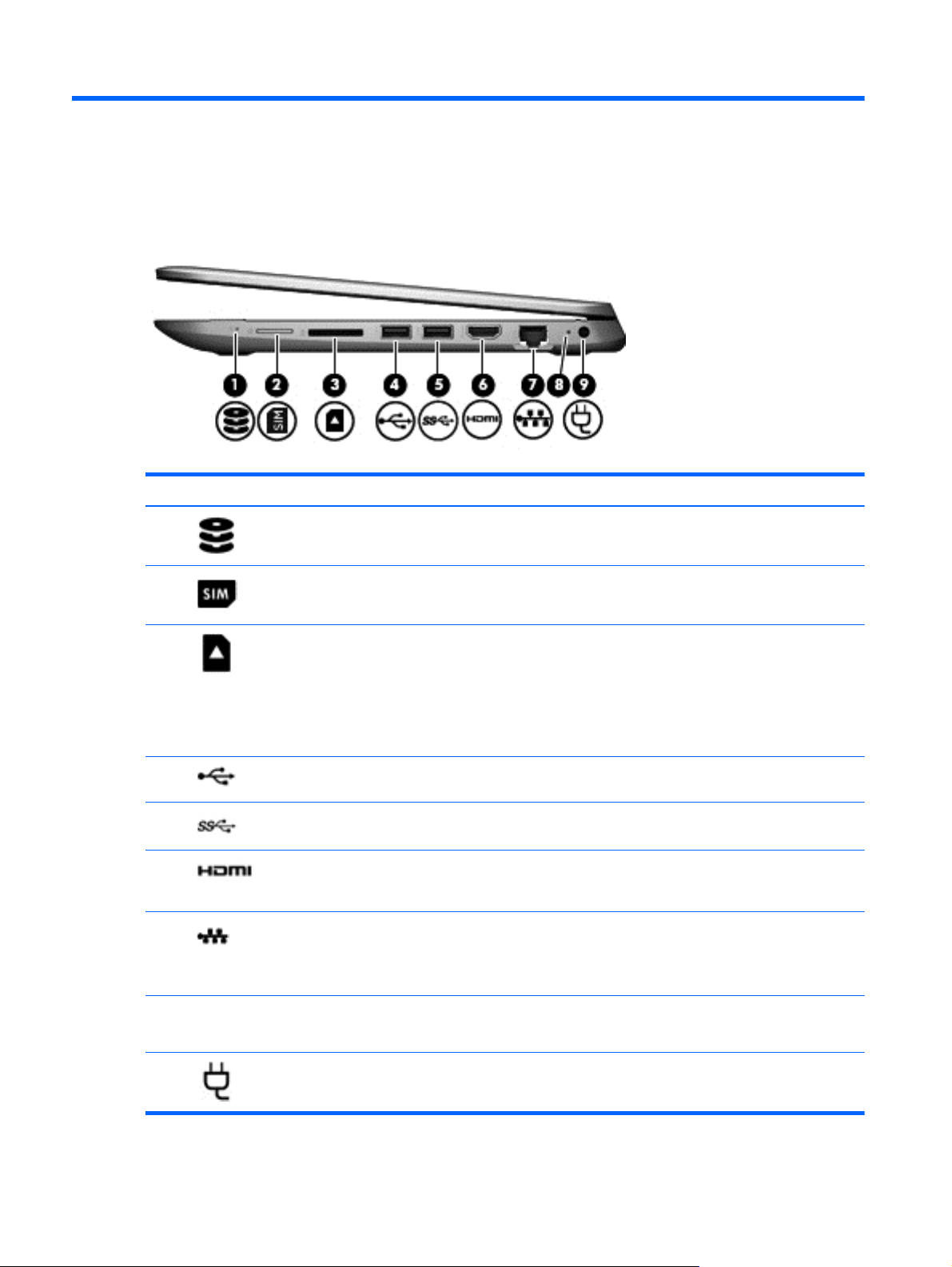
2 External component identification
Right side
Component Description
(1)
(2)
(3)
(4)
(5)
(6)
(7)
Hard drive light
SIM slot (select models only) Supports a wireless subscriber identity module (SIM).
Memory card reader Reads optional memory cards that enable you to store, manage, share,
USB 2.0 port Connects an optional USB device, such as a keyboard, mouse, external
USB 3.0 port Connects an optional USB device, such as a keyboard, mouse, external
HDMI port Connects an optional video or audio device, such as a high-definition
RJ-45 (network) jack/status lights Connects a network cable.
●
Blinking white: The hard drive is being accessed.
●
Amber: HP 3D DriveGuard has temporarily parked the hard drive.
or access information.
To insert a card, hold the card label-side up, with connectors facing the
slot, insert the card into the slot, and then push in on the card until it is
firmly seated.
To remove a card, press in on the card it until it pops out.
drive, printer, scanner or USB hub.
drive, printer, scanner or USB hub.
television, any compatible digital or audio component, or a high-speed
High-Definition Multimedia Interface (HDMI) device.
●
White: The network is connected.
●
Amber: Activity is occurring on the network.
(8) AC adapter light
(9)
Power connector Connects an AC adapter.
4 Chapter 2 External component identification
●
On: The AC adapter is connected and the battery is charged.
●
Off: The computer is using battery power.
Page 13

Left side
Component Description
(1) Security cable slot Attaches an optional security cable to the computer.
NOTE: The security cable is designed to act as a deterrent, but
it may not prevent the computer from being mishandled or
stolen.
(2)
(3) Power light
Power button
●
When the computer is off, press the button to turn on the
computer.
●
When the computer is on, press the button briefly to
initiate Sleep.
●
When the computer is in the Sleep state, press the button
briefly to exit Sleep.
●
When the computer is in Hibernation, press the button
briefly to exit Hibernation.
CAUTION: Pressing and holding down the power button will
result in the loss of unsaved information.
If the computer has stopped responding and Windows
shutdown procedures are ineffective, press and hold the power
button down for at least 5 seconds to turn off the computer.
To learn more about your power settings, see your power
options. From the Start screen, type power, select Power and
sleep settings, and then select Power and sleep from the list of
applications.
●
On: The computer is on.
●
Blinking: The computer is in the Sleep state, a powersaving state. The computer shuts off power to the display
and other unneeded components.
●
Off: The computer is off or in Hibernation. Hibernation is a
power-saving state that uses the least amount of power.
(4) Vent Enables airflow to cool internal components.
NOTE: The computer fan starts up automatically to cool
internal components and prevent overheating. It is normal for
the internal fan to cycle on and off during routine operation.
(5)
(6)
USB 2.0 port Connects an optional USB device, such as a keyboard, mouse,
external drive, printer, scanner or USB hub.
Audio-out (headphone)/Audio-in (microphone)
jack
Connects optional powered stereo speakers, headphones,
earbuds, a headset, or a television audio cable. Also connects an
Left side 5
Page 14
Component Description
optional headset microphone. This jack does not support
optional microphone-only devices.
WARNING! To reduce the risk of personal injury, adjust the
volume before putting on headphones, earbuds, or a headset.
For additional safety information, refer to the Regulatory,
Safety, and Environmental Notices.,
To access this document:
●
From the Start screen, type support, and then select the
HP Support Assistant app.
– or —
●
From the Windows desktop, click the question mark icon in
the notification area, at the far right of the taskbar.
NOTE: When a device is connected to the jack, the computer
speakers are disabled.
NOTE: Be sure that the device cable has a 4-conductor
connector that supports both audio-out (headphone) and audioin (microphone).
(7)
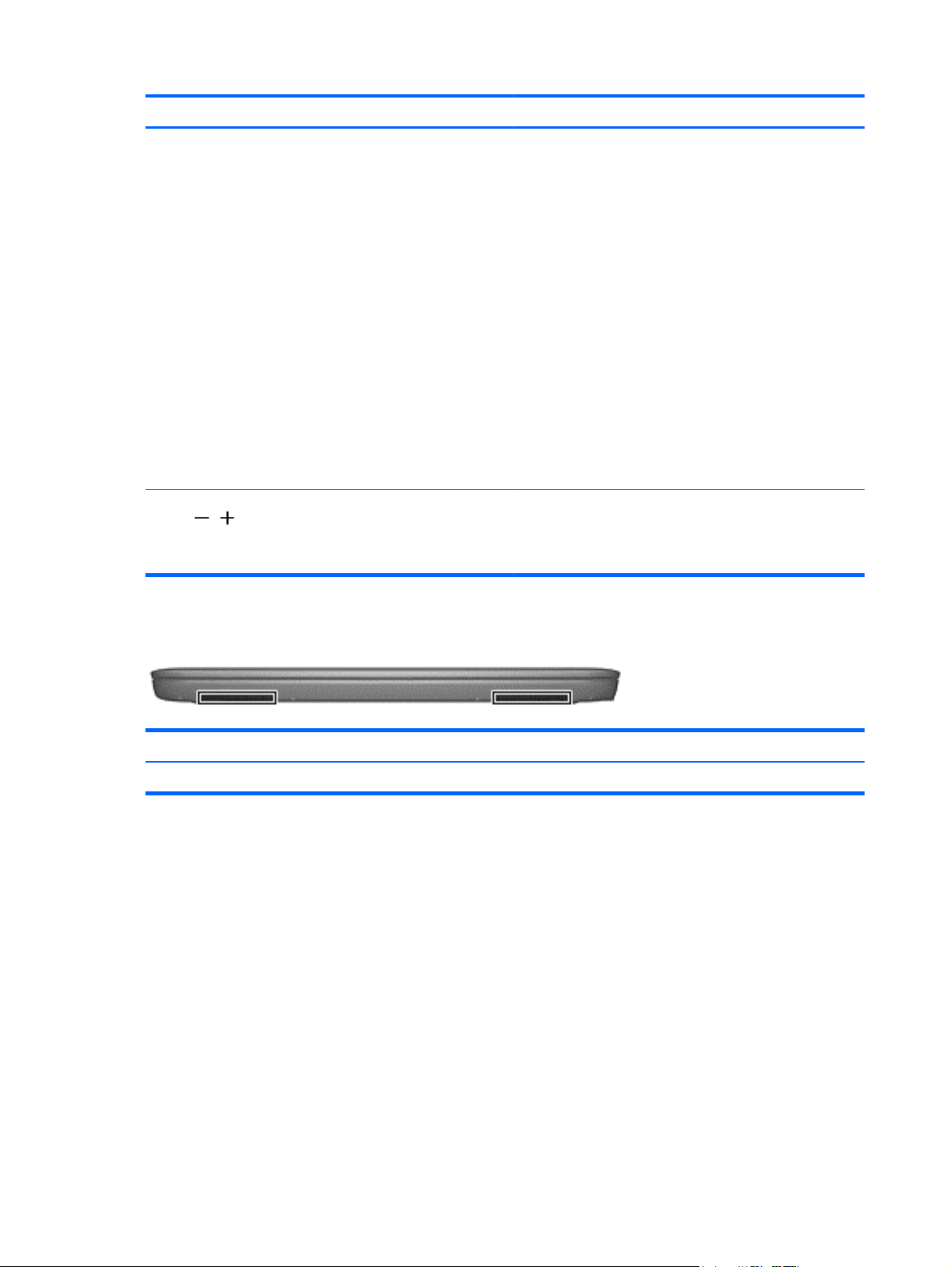
Speakers
Component Description
Speakers (2) Produce sound.
Volume button Controls speaker volume.
To decrease speaker volume, press the – edge of the button.
To increase speaker volume, press the + edge of the button.
6 Chapter 2 External component identification
Page 15
Display
Component Description
(1) Webcam light On: The webcam is in use.
(2) Webcam Records video and captures photographs. Some models allow you to
video conference and chat online using streaming video.
To use the webcam, from the Start screen, type camera, and then
select Camera from the list of applications.
(3) Internal microphone Records sound.
(4) WLAN antenna* Sends and receives wireless signals to communicate with wireless
local area networks (WLANs).
(5) Internal display switch Turns off the display and initiates Sleep if the display is closed while
the power is on.
NOTE: The internal display switch is not visible from the outside of
the computer.
*The antennas are not visible from the outside of the computer. For optimal transmission, keep the areas immediately around the
antennas free from obstructions. For wireless regulatory notices, see the section of the Regulatory, Safety, and Environmental Notices
that applies to your country or region.
To access this document:
From the Start screen, type support, and then select the HP Support Assistant app.
Display 7
Page 16

Your computer can function as a classic notebook, and in addition, the display can be rotated so that the
computer transforms into an entertainment stand or a tablet.
Changing your notebook to an entertainment stand
To change your notebook to an entertainment stand, raise the display, and then rotate the display backward
to a stand position (about 315 degrees).
Changing your notebook to a tablet
To change your notebook to a tablet, raise the display, and then rotate the display backward until it is flush
with the computer bottom (360 degrees).
8 Chapter 2 External component identification
Page 17

Top
TouchPad
Component Description
(1) TouchPad zone Reads your finger gestures to move the pointer or activate
items on the screen.
NOTE: The TouchPad also supports edge-swipe gestures.
(2) Left TouchPad button Functions like the left button on an external mouse.
(3) Right TouchPad button Functions like the right button on an external mouse.
Top 9
Page 18

Lights
Component Description
(1) Caps lock light On: Caps lock is on, which switches the keys to all capital letters.
(2)
Mute light
●
Amber: Computer sound is off.
●
Off: Computer sound is on.
10 Chapter 2 External component identification
Page 19

Keys
Component Description
(1) esc key Displays system information when pressed in combination with
the fn key.
(2) fn key Executes frequently used system functions when pressed in
combination with the esc key, or on select models, the b key or
the spacebar.
(3)
(4) Action keys Execute frequently used system functions.
Windows key Returns you to the Start screen from an open app or the
Windows desktop.
NOTE: Pressing the Windows key again will return you to the
previous screen.
NOTE: On select models, the f5 action key turns the radiance
backlight keybard feature off or on.
Top 11
Page 20

Service tag and PCID label
Service tag
When ordering parts or requesting information, provide the computer serial number and model description
provided on the service tag.
●
Serial number (s/n) (1). This is an alphanumeric identifier that is unique to each product.
●
Part number/Product number (p/n) (2). This number provides specific information about the product's
hardware components. The part number helps a service technician to determine what components and
parts are needed.
●
Model/Warranty period (3).
Model is the alphanumeric identifier used to locate documents, drivers, and support for the computer.
Warranty describes the duration (in years) of the warranty period for the computer.
12 Chapter 2 External component identification
Page 21

PCID label
The PCID label provides the information required to properly reset the notebook firmware (BIOS) back to
factory shipped specifications when replacing the system board. The label may have a different number of
characters depending on the operating system on the computer.
Windows 8 models
Non-Windows 8 models
Service tag and PCID label 13
Page 22

3 Illustrated parts catalog
Computer major components
NOTE: HP continually improves and changes product parts. For complete and current information on
supported parts for your computer, go to
follow the on-screen instructions.
http://partsurfer.hp.com, select your country or region, and then
14 Chapter 3 Illustrated parts catalog
Page 23

Item Component Spare part number
(1) Display assembly (11.6-in [29.5-cm], AG, SVA, LED TouchScreen) (includes webcam/
microphone module)
(2) Top cover (includes TouchPad)
Silver 781865-001
Red 790943-001
(3) TouchPad button board (includes bracket and cable) not spared
(4) Power connector cable 755727-001
(5) Keyboard
NOTE: For a detailed list of available keyboards, see
For use in Brazil 755896-201
For use in Canada 755896-DB1
For use in Japan 755896-291
For use in Latin America 755896-161
For use in the United States 755896-001
For use in Russia 785454-251
(6) System board (includes replacement thermal material):
Intel Pentium N3540 processor and the Windows 8.1 Professional operating system on
models with a 3 cell battery
Sequential part number listing on page 19.
755730-001
794721-601
Intel Pentium N3540 processor and the Windows 8.1 Standard operating system on models
with a 3 cell battery
Intel Pentium N3540 processor and the Windows 8.1 Professional operating system on
models with a 2 cell battery
Intel Pentium N3540 processor and the Windows 8.1 Standard operating system on models
with a 2 cell battery
Intel Pentium N3540 processor and a non-Windows 8.1 operating system on models with a
2 cell battery
Intel Pentium N3530 processor and the Windows 8.1 Professional operating system on
models with a 3 cell battery
Intel Pentium N3530 processor and the Windows 8.1 Standard operating system on models
with a 3 cell battery
Intel Pentium N3530 processor and a non-Windows 8.1 operating system on models with a
3 cell battery
Intel Pentium N3530 processor and the Windows 8.1 Professional operating system on
models with a 2 cell battery
Intel Pentium N3530 processor and the Windows 8.1 Standard operating system on models
with a 2 cell battery
Intel Pentium N3530 processor and a non-Windows 8.1 operating system on models with a
2 cell battery
Intel Pentium N2840 processor and the Windows 8.1 Professional operating system on
models with a 3 cell battery
794721-501
793104-601
793104-501
793104-001
793103-601
793103-501
793103-001
774996-601
774996-501
774996-001
794722-601
Computer major components 15
Page 24

Item Component Spare part number
Intel Pentium N2840 processor and the Windows 8.1 Standard operating system on models
with a 3 cell battery
Intel Pentium N2840 processor and a non-Windows 8.1 operating system on models with a
3 cell battery
Intel Pentium N2840 processor and the Windows 8.1 Professional operating system on
models with a 2 cell battery
Intel Pentium N2840 processor and the Windows 8.1 Standard operating system on models
with a 2 cell battery
Intel Pentium N2840 processor and a non-Windows 8.1 operating system on models with a
2 cell battery
Intel Pentium N2830 processor and the Windows 8.1 Professional operating system on
models with a 2 cell battery
Intel Pentium N2830 processor and the Windows 8.1 Standard operating system on models
with a 2 cell battery
Intel Pentium N2830 processor and a non-Windows 8.1 operating system on models with a
2 cell battery
(7) Speaker Kit (includes left and right speakers and cable) 755738-001
(8) RTC battery (includes cable) 755735-001
(9) Heat sink (includes replacement thermal material) 755728-001
(10) Fan 755729-001
794722-501
794722-001
793105-601
793105-501
793105-001
774997-601
774997-501
774997-001
(11) Power button board (includes cable) 755733-001
(12) Hard drive (does not include hard drive bracket, hard drive connector cable, or screws):
750-GB, 5400-rpm, 7.0-mm 752099-001
500-GB, 5400-rpm, 8 GB hybrid SSD, 7.0-mm 732000-005
500-GB, 5400-rpm, 7.0-mm 683802-005
Hard Drive Hardware Kit (not illustrated, includes hard drive bracket, hard drive connector
cable, and screws)
Solid-State Drives
256 GB solid-state drive (SSD), M.2 788297-001
128 GB solid-state drive (SSD), M.2, TLC 777774-001
(13) Memory module (PC3L, 12800, 1600-MHz):
8-GB 693374-005
4-GB 691740-005
(14) WLAN module:
Realtek RTL8188EE 802.11bgn Wi-Fi Adapter 709848-005
Qualcomm QCA9565 802.11bgn 1x1 Wi-Fi + BT4.0 Combo Adapter 733476-005
(15) Li-ion battery
755740-001
2-cell, 29-Wh, 3.82-Ah 751875-005
16 Chapter 3 Illustrated parts catalog
Page 25

Item Component Spare part number
3-cell, 43-Wh, 3.82-Ah 778956-005
(16) USB board (includes cable) 755734-001
(17) Bottom cover
Red models with 3 cell battery 784782-001
Red models with 2 cell battery 755725-001
Silver models with 3 cell battery 790944-001
Silver models with 2 cell battery 755726-001
Mass storage devices
Component Spare part number
Hard drive (does not include hard drive bracket, hard drive connector cable, or screws):
750-GB, 5400-rpm, 7.0-mm 752099-001
500-GB, 5400-rpm, 8 GB hybrid SSD, 7.0-mm 732000-005
500-GB, 5400-rpm, 7.0-mm 683802-005
Hard Drive Hardware Kit (includes hard drive bracket, connector cable, and screws) 755740-001
Solid-State Drives
256 GB solid-state drive (SSD), M.2 788297-001
128 GB solid-state drive (SSD), M.2, TLC 777774-001
Miscellaneous parts
Component Spare part number
AC adapter
45-W HP Smart AC adapter (non-PFC, 4.5-mm, non-slim) 741727-001
Power cord (3-pin, black, 1.0-m):
For use in Europe 755530-021
For use in Israel 755530-BB1
For use in North America 755530-001
For use in South Africa 755530-AR1
For use in the United Kingdom and Singapore 755530-031
Rubber Feet Kit (includes 2 rear rubber feet) 755736-001
Screw Kit 755737-001
Mass storage devices 17
Page 26
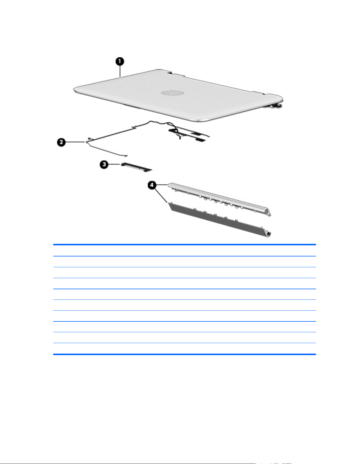
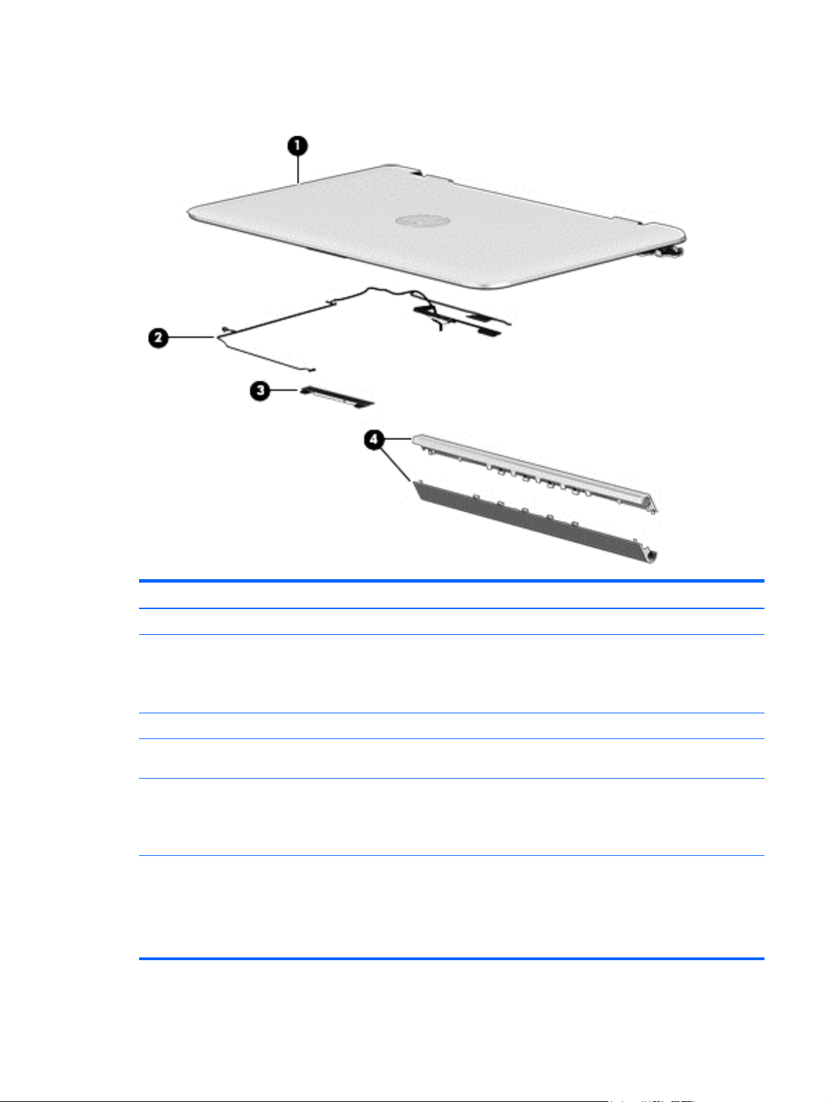
Display assembly subcomponents
Item Component Spare part number
(1) Display enclosure
Silver models 758845-001
Red models 758846-001
(2) Display cable 761350-001
(3) Webcam 758848-001
(4) Display hinge covers
For use in red models 758847-001
For use in silver models 759503-001
Sensor board (not illustrated) 788218-001
18 Chapter 3 Illustrated parts catalog
Page 27

Sequential part number listing
CSR flag designations:
A = Mandatory
B = Optional
C = Service technician recommended
N = Non-user replaceable
Spare part number CSR flag Description
683802-005 N Hard drive, 500-GB, 5400-rpm, 7.0-mm
691740-005 N 4-GB memory module (PC3L, 12800, 1600-MHz)
693374-005 N 8-GB memory module (PC3L, 12800, 1600-MHz)
709848-005 N Realtek RTL8188EE 802.11bgn Wi-Fi Adapter
732000-005 N 500-GB, 5400-rpm, 8 GB hybrid SSD, 7.0-mm
NOTE: The hard drive bracket, hard drive connector cable, and screws are included in the Hard
Drive Hardware Kit, spare part number 755740-001.
733476-005 N Qualcomm QCA9565 802.11bgn 1x1 Wi-Fi + BT4.0 Combo Adapter
741727-001 A 45-W HP Smart AC adapter (non-PFC, 4.5-mm, non-slim)
751875-005 N 2-cell, 29-Wh, 3.82-Ah, Li-ion battery for use in all models
752099-001 A 750-GB, 5400-rpm, 8 GB hybrid SSD, 7.0-mm
NOTE: The hard drive bracket, hard drive connector cable, and screws are included in the Hard
Drive Hardware Kit, spare part number 755740-001.
755530-001 A Power cord for use in North America (3-pin, black, 1.0-m)
755530-021 A Power cord for use in the United Kingdom and Singapore (3-pin, black, 1.0-m)
755530-031 A Power cord for use in the United Kingdom and Singapore (3-pin, black, 1.0-m)
755530-AR1 A Power cord for use in South Africa (3-pin, black, 1.0-m)
755530-BB1 A Power cord for use in Israel (3-pin, black, 1.0-m)
755725-001 N Bottom cover for use in red models with a 2 cell battery
755726-001 N Bottom cover for use in silver models with a 2 cell battery
755727-001 N Power connector cable
755728-001 N Heat sink (includes replacement thermal material)
755729-001 N Fan
755730-001 N 11.6-in [29.5-cm], AG, SVA, LED TouchScreen display assembly
755733-001 N Power button board (includes cable)
755734-001 N USB board (includes cable)
755735-001 N RTC battery (includes cable)
755736-001 N Rubber Feet Kit (includes 2 rubber feet)
Sequential part number listing 19
Page 28

Spare part number CSR flag Description
755737-001 N Screw Kit
755738-001 N Speaker Kit (includes left and right speakers and cable)
755740-001 N Hard Drive Hardware Kit (includes hard drive bracket, hard drive connector cable, and screws)
755896-001 N Keyboard for use in the United States (includes keyboard cable and TouchPad)
755896-161 N Keyboard for use in Latin America (includes keyboard cable and TouchPad)
755896-201 N Keyboard for use in Brazil (includes keyboard cable and TouchPad)
755896-291 N Keyboard for use in Japan (includes keyboard cable and TouchPad)
755896-DB1 N Keyboard for use in Canada (includes keyboard cable and TouchPad)
758845-001 N Display rear cover for use in silver models
758846-001 N Display rear cover for use in red models
758847-001 N Display hinge covers for use in all red models
758848-001 N Webcam
759503-001 N Display hinge covers for use in all silver models
761350-001 N Display cable
774996-001 N System board equipped with an Intel Pentium N3530 processor and a non-Windows 8.1 operating
system for use in models with a 2 cell battery
774996-501 N System board equipped with an Intel Pentium N3530 processor and the Windows 8.1 Standard
operating system for use in models with a 2 cell battery
774996-601 N System board equipped with an Intel Pentium N3530 processor and the Windows 8.1 Professional
operating system for use in models with a 2 cell battery
774997-001 N System board equipped with an Intel Pentium N2830 processor and a non-Windows 8.1 operating
system for use in models with a 2 cell battery
774997-501 N System board equipped with an Intel Pentium N2830 processor and the Windows 8.1 Standard
operating system for use in models with a 2 cell battery
774997-601 N System board equipped with an Intel Pentium N2830 processor and the Windows 8.1 Professional
operating system for use in models with a 2 cell battery
777774-001 N 128 GB Solid-state drive (SSD), M.2, TLC
778956-005 N 3-cell, 43-Wh, 3.82-Ah, Li-ion battery
781865-001 C Top cover for use in silver models (includes TouchPad)
784782-001 N Bottom cover for use in red models with a 3 cell battery
785454-251 B Keyboard for use in Russia (includes keyboard cable and TouchPad)
788218-001 N Sensor board
788297-001 N 256 GB Solid-state drive (SSD), M.2
790943-001 N Top cover for use in red models (includes TouchPad)
790944-001 N Bottom cover for use in silver models with a 3 cell battery
793103-001 N System board equipped with an Intel Pentium N3530 processor and a non-Windows 8.1 operating
20 Chapter 3 Illustrated parts catalog
system for use in models with a 3 cell battery
Page 29

Spare part number CSR flag Description
793103-501 N System board equipped with an Intel Pentium N3530 processor and the Windows 8.1 Standard
operating system for use in models with a 3 cell battery
793103-601 N System board equipped with an Intel Pentium N3530 processor and the Windows 8.1 Professional
operating system for use in models with a 3 cell battery
793104-001 N System board equipped with an Intel Pentium N3540 processor and a non-Windows 8.1 operating
system for use in models with a 2 cell battery
793104-501 N System board equipped with an Intel Pentium N3540 processor and the Windows 8.1 Standard
operating system for use in models with a 2 cell battery
793104-601 N System board equipped with an Intel Pentium N3540 processor and the Windows 8.1 Professional
operating system for use in models with a 2 cell battery
793105-001 N System board equipped with an Intel Pentium N2840 processor and a non-Windows 8.1 operating
system for use in models with a 2 cell battery
793105-501 N System board equipped with an Intel Pentium N2840 processor and the Windows 8.1 Standard
operating system for use in models with a 2 cell battery
793105-601 N System board equipped with an Intel Pentium N2840 processor and the Windows 8.1 Professional
operating system for use in models with a 2 cell battery
794721-001 N System board equipped with an Intel Pentium N3540 processor and a non-Windows 8.1 operating
system for use in models with a 3 cell battery
794721-501 N System board equipped with an Intel Pentium N3540 processor and the Windows 8.1 Standard
operating system for use in models with a 3 cell battery
794721-601 N System board equipped with an Intel Pentium N3540 processor and the Windows 8.1 Professional
operating system for use in models with a 3 cell battery
794722-001 N System board equipped with an Intel Pentium N2840 processor and a non-Windows 8.1 operating
system for use in models with a 3 cell battery
794722-501 N System board equipped with an Intel Pentium N2840 processor and the Windows 8.1 Standard
operating system for use in models with a 3 cell battery
794722-601 N System board equipped with an Intel Pentium N2840 processor and the Windows 8.1 Professional
operating system for use in models with a 3 cell battery
Sequential part number listing 21
Page 30

4 Removal and replacement procedures
preliminary requirements
Tools required
You will need the following tools to complete the removal and replacement procedures:
●
Flat-bladed screw driver
●
Magnetic screw driver
●
Phillips P0 and P1 screw drivers
Service considerations
The following sections include some of the considerations that you must keep in mind during disassembly
and assembly procedures.
NOTE: As you remove each subassembly from the computer, place the subassembly (and all accompanying
screws) away from the work area to prevent damage.
Plastic parts
CAUTION: Using excessive force during disassembly and reassembly can damage plastic parts. Use care
when handling the plastic parts. Apply pressure only at the points designated in the
maintenance instructions.
22 Chapter 4 Removal and replacement procedures preliminary requirements
Page 31

Cables and connectors
CAUTION: When servicing the computer, be sure that cables are placed in their proper locations during the
reassembly process. Improper cable placement can damage the computer.
Cables must be handled with extreme care to avoid damage. Apply only the tension required to unseat or
seat the cables during removal and insertion. Handle cables by the connector whenever possible. In all cases,
avoid bending, twisting, or tearing cables. Be sure that cables are routed in such a way that they cannot be
caught or snagged by parts being removed or replaced. Handle flex cables with extreme care; these cables
tear easily.
Drive handling
CAUTION: Drives are fragile components that must be handled with care. To prevent damage to
the computer, damage to a drive, or loss of information, observe these precautions:
Before removing or inserting a hard drive, shut down the computer. If you are unsure whether the computer
is off or in Hibernation, turn the computer on, and then shut it down through the operating system.
Before handling a drive, be sure that you are discharged of static electricity. While handling a drive, avoid
touching the connector.
Before removing a diskette drive or optical drive, be sure that a diskette or disc is not in the drive and be sure
that the optical drive tray is closed.
Handle drives on surfaces covered with at least one inch of shock-proof foam.
Avoid dropping drives from any height onto any surface.
After removing a hard drive, an optical drive, or a diskette drive, place it in a static-proof bag.
Avoid exposing an internal hard drive to products that have magnetic fields, such as monitors or speakers.
Avoid exposing a drive to temperature extremes or liquids.
If a drive must be mailed, place the drive in a bubble pack mailer or other suitable form of protective
packaging and label the package “FRAGILE.”
Service considerations 23
Page 32

Grounding guidelines
Electrostatic discharge damage
Electronic components are sensitive to electrostatic discharge (ESD). Circuitry design and structure
determine the degree of sensitivity. Networks built into many integrated circuits provide some protection,
but in many cases, ESD contains enough power to alter device parameters or melt silicon junctions.
A discharge of static electricity from a finger or other conductor can destroy static-sensitive devices or
microcircuitry. Even if the spark is neither felt nor heard, damage may have occurred.
An electronic device exposed to ESD may not be affected at all and can work perfectly throughout a normal
cycle. Or the device may function normally for a while, then degrade in the internal layers, reducing its life
expectancy.
CAUTION: To prevent damage to the computer when you are removing or installing internal components,
observe these precautions:
Keep components in their electrostatic-safe containers until you are ready to install them.
Before touching an electronic component, discharge static electricity by using the guidelines described in this
section.
Avoid touching pins, leads, and circuitry. Handle electronic components as little as possible.
If you remove a component, place it in an electrostatic-safe container.
The following table shows how humidity affects the electrostatic voltage levels generated by
different activities.
CAUTION: A product can be degraded by as little as 700 V.
Typical electrostatic voltage levels
Relative humidity
Event 10% 40% 55%
Walking across carpet 35,000 V 15,000 V 7,500 V
Walking across vinyl floor 12,000 V 5,000 V 3,000 V
Motions of bench worker 6,000 V 800 V 400 V
Removing DIPS from plastic tube 2,000 V 700 V 400 V
Removing DIPS from vinyl tray 11,500 V 4,000 V 2,000 V
Removing DIPS from Styrofoam 14,500 V 5,000 V 3,500 V
Removing bubble pack from PCB 26,500 V 20,000 V 7,000 V
Packing PCBs in foam-lined box 21,000 V 11,000 V 5,000 V
24 Chapter 4 Removal and replacement procedures preliminary requirements
Page 33

Packaging and transporting guidelines
Follow these grounding guidelines when packaging and transporting equipment:
●
To avoid hand contact, transport products in static-safe tubes, bags, or boxes.
●
Protect ESD-sensitive parts and assemblies with conductive or approved containers or packaging.
●
Keep ESD-sensitive parts in their containers until the parts arrive at static-free workstations.
●
Place items on a grounded surface before removing items from their containers.
●
Always be properly grounded when touching a component or assembly.
●
Store reusable ESD-sensitive parts from assemblies in protective packaging or nonconductive foam.
●
Use transporters and conveyors made of antistatic belts and roller bushings. Be sure that mechanized
equipment used for moving materials is wired to ground and that proper materials are selected to avoid
static charging. When grounding is not possible, use an ionizer to dissipate electric charges.
Workstation guidelines
Follow these grounding workstation guidelines:
●
Cover the workstation with approved static-shielding material.
●
Use a wrist strap connected to a properly grounded work surface and use properly grounded tools and
equipment.
●
Use conductive field service tools, such as cutters, screw drivers, and vacuums.
●
When fixtures must directly contact dissipative surfaces, use fixtures made only of staticsafe materials.
●
Keep the work area free of nonconductive materials, such as ordinary plastic assembly aids
and Styrofoam.
●
Handle ESD-sensitive components, parts, and assemblies by the case or PCM laminate. Handle these
items only at static-free workstations.
●
Avoid contact with pins, leads, or circuitry.
●
Turn off power and input signals before inserting or removing connectors or test equipment.
Grounding guidelines 25
Page 34

Equipment guidelines
Grounding equipment must include either a wrist strap or a foot strap at a grounded workstation.
●
When seated, wear a wrist strap connected to a grounded system. Wrist straps are flexible straps with a
minimum of one megohm ±10% resistance in the ground cords. To provide proper ground, wear a strap
snugly against the skin at all times. On grounded mats with banana-plug connectors, use alligator clips
to connect a wrist strap.
●
When standing, use foot straps and a grounded floor mat. Foot straps (heel, toe, or boot straps) can be
used at standing workstations and are compatible with most types of shoes or boots. On conductive
floors or dissipative floor mats, use foot straps on both feet with a minimum of one megohm resistance
between the operator and ground. To be effective, the conductive must be worn in contact with the
skin.
The following grounding equipment is recommended to prevent electrostatic damage:
●
Antistatic tape
●
Antistatic smocks, aprons, and sleeve protectors
●
Conductive bins and other assembly or soldering aids
●
Nonconductive foam
●
Conductive tabletop workstations with ground cords of one megohm resistance
●
Static-dissipative tables or floor mats with hard ties to the ground
●
Field service kits
●
Static awareness labels
●
Material-handling packages
●
Nonconductive plastic bags, tubes, or boxes
●
Metal tote boxes
●
Electrostatic voltage levels and protective materials
The following table lists the shielding protection provided by antistatic bags and floor mats.
Material Use Voltage protection level
Antistatic plastics Bags 1,500 V
Carbon-loaded plastic Floor mats 7,500 V
Metallized laminate Floor mats 5,000 V
26 Chapter 4 Removal and replacement procedures preliminary requirements
Page 35

5 Removal and replacement procedures for
Authorized Service Provider parts
CAUTION: Components described in this chapter should only be accessed by an authorized service provider.
Accessing these parts can damage the computer or void the warranty.
NOTE: HP continually improves and changes product parts. For complete and current information on
supported parts for your computer, go to
follow the on-screen instructions.
Component replacement procedures
This chapter provides removal and replacement procedures for Authorized Service Provider only parts.
There are as many as 76 screws that must be removed, replaced, and/or loosened when servicing the
computer. Make special note of each screw size and location during removal and replacement.
http://partsurfer.hp.com, select your country or region, and then
Component replacement procedures 27
Page 36

Bottom cover
Description Spare part number
Bottom cover for use in:
Red models with a 3 cell battery 784782-001
Red models with a 2 cell battery 755725-001
Silver models with a 3 cell battery 790944-001
Silver models with a 2 cell battery 755726-001
Rubber Kit (includes rear feet) 755736-001
Before removing the bottom cover, follow these steps:
1. Turn off the computer. If you are unsure whether the computer is off or in Hibernation, turn the
computer on, and then shut it down through the operating system.
2. Disconnect the power from the computer by unplugging the power cord from the computer.
3. Disconnect all external devices from the computer.
Remove the bottom cover:
1. Position the computer upside-down.
2. Pry the two rear rubber feet off the bottom cover (1).
3. Remove the two Phillips PM2.5×8.0 screws (2) that secure the bottom cover to the computer.
28 Chapter 5 Removal and replacement procedures for Authorized Service Provider parts
Page 37

4. Remove the two Phillips PM2.5×8.0 screws (1) and the seven Phillips PM2.0×7.0 screws (2) that secure
the bottom cover to the computer.
5. Separate the bottom cover from the computer by lifting up at the seam near the display hinges (1), and
then lift the cover up and off the computer (2) far enough to access the USB/audio board connector on
the system board.
NOTE: When you lift the bottom cover, a cable is connected from the USB/audio board (installed on
the inside of the bottom cover) to the system board. Be sure not to pull the cable loose when lifting the
bottom cover.
Component replacement procedures 29
Page 38

6. Disconnect the USB/audio board cable from the system board by lifting the ZIF connector (1), and then
removing the USB/audio board cable from the system board connector (2).
Reverse this procedure to install the bottom cover.
30 Chapter 5 Removal and replacement procedures for Authorized Service Provider parts
Page 39

USB/audio board
Description Spare part number
USB/audio board (includes cable) 755734-001
Before removing the USB/audio board, follow these steps:
1. Shut down the computer. If you are unsure whether the computer is off or in Hibernation, turn the
computer on, and then shut it down through the operating system.
2. Disconnect all external devices connected to the computer.
3. Disconnect the power from the computer by first unplugging the power cord from the AC outlet and
then unplugging the AC adapter from the computer.
4. Remove the bottom cover (see
Bottom cover on page 28).
To remove the USB/audio board:
1. Position the bottom cover upside-down.
2. Remove the Phillips PM2.0×3.0 screw (1).
3. Lift up on the rear of the board and lift the board off the bottom cover (2).
Reverse this procedure to install the USB/audio board.
Component replacement procedures 31
Page 40

WLAN module
Description Spare part number
Realtek RTL8188EE 802.11bgn Wi-Fi Adapter 709848-005
Qualcomm QCA9565 802.11bgn 1x1 Wi-Fi + BT4.0 Combo Adapter 733476-005
CAUTION: To prevent an unresponsive system, replace the wireless module only with a wireless module
authorized for use in the computer by the governmental agency that regulates wireless devices in your
country or region. If you replace the module and then receive a warning message, remove the module to
restore device functionality, and then contact technical support.
Before removing the WLAN module, follow these steps:
1. Turn off the computer. If you are unsure whether the computer is off or in Hibernation, turn the
computer on, and then shut it down through the operating system.
2. Disconnect the power from the computer by unplugging the power cord from the computer.
3. Disconnect all external devices from the computer.
4. Remove the bottom cover (see
Bottom cover on page 28).
5. Disconnect the battery.
Remove the WLAN module:
1. Disconnect the WLAN antenna cable (1) from the terminal on the WLAN module.
NOTE: The WLAN antenna cable connects to the WLAN module “Main” terminal labeled “1”.
2. Remove the two Phillips PM2.0×3.5 screws (2) that secure the WLAN module to the system board. (The
WLAN module tilts up.)
32 Chapter 5 Removal and replacement procedures for Authorized Service Provider parts
Page 41

3. Remove the WLAN module (3) by pulling the module away from the slot at an angle.
NOTE: If the WLAN antenna cables are not connected to the terminals on the WLAN module, the protective
sleeves must be installed on the antenna connectors, as shown in the following illustration.
Reverse this procedure to install the WLAN module.
Component replacement procedures 33
Page 42

Solid-state drive (M.2)
Description Spare part number
256 GB Solid-state drive (SSD), M.2 788297-001
128 GB solid-state drive (SSD), M.2, TLC 777774-001
Before removing the solid-state drive, follow these steps:
1. Turn off the computer. If you are unsure whether the computer is off or in Hibernation, turn the
computer on, and then shut it down through the operating system.
2. Disconnect the power from the computer by unplugging the power cord from the computer.
3. Disconnect all external devices from the computer.
4. Remove the bottom cover (see
Bottom cover on page 28).
5. Disconnect the battery.
Remove the solid-state drive:
1. Remove the Phillips PM2.0×3.5 screw (1) that secures the solid-state drive to the system board.
2. Remove the solid-state drive (2) by pulling the drive away from the slot at an angle.
34 Chapter 5 Removal and replacement procedures for Authorized Service Provider parts
Page 43

Reverse this procedure to install the solid-state drive.
Component replacement procedures 35
Page 44

Hard drive
NOTE: The Hard Drive Hardware Kit, spare part number 755740-001, includes the hard drive bracket, hard
drive connector cable, and screws.
Description Spare part number
750-GB, 5400-rpm, 7.0-mm 752099-001
500-GB, 5400-rpm, 8 GB hybrid SSD, 7.0-mm 732000-005
500-GB, 5400-rpm, 7.0-mm 683802-005
Before removing the hard drive, follow these steps:
1. Turn off the computer. If you are unsure whether the computer is off or in Hibernation, turn the
2. Disconnect the power from the computer by unplugging the power cord from the computer.
3. Disconnect all external devices from the computer.
computer on, and then shut it down through the operating system.
4. Remove the bottom cover (see
Bottom cover on page 28).
5. Disconnect the battery.
Remove the hard drive:
1. Disconnect the hard drive connector cable (1) from the system board.
2. Remove the Phillips PM2.0×7.0 screw (2) that secures the hard drive and battery to the computer.
3. Remove the three Phillips PM2.0×3.0 screws (3) that secure the hard drive to the computer.
36 Chapter 5 Removal and replacement procedures for Authorized Service Provider parts
Page 45

4. A small part of the hard drive sits under one of the battery screw tabs (4). To remove it, slide the hard
drive toward the top of the computer (5), and then lift it out of the computer (6).
5. If it is necessary to disassemble the hard drive, perform the following steps:
a. Disconnect the hard drive connector cable (1) from the hard drive.
b. Remove the four Phillips PM3.0×3.0 screws (2) that secure the hard drive bracket to the hard
drive.
c. Remove the hard drive bracket (3) from the hard drive.
The hard drive bracket, hard drive connector cable, and screws are available in the Hard Drive
Hardware Kit, spare part number 755740-001.
Component replacement procedures 37
Page 46

Reverse this procedure to install the hard drive.
38 Chapter 5 Removal and replacement procedures for Authorized Service Provider parts
Page 47

RTC battery
Description Spare part number
RTC battery (includes cable) 755735-001
Before removing the RTC battery, follow these steps:
1. Turn off the computer. If you are unsure whether the computer is off or in Hibernation, turn the
2. Disconnect the power from the computer by unplugging the power cord from the computer.
3. Disconnect all external devices from the computer.
computer on, and then shut it down through the operating system.
4. Remove the bottom cover (see
Bottom cover on page 28).
5. Disconnect the battery.
Remove the RTC battery:
1. Disconnect the RTC battery cable (1) from the system board.
Component replacement procedures 39
Page 48

2. Detach the RTC battery (2) from the system board. (The RTC battery is secured with double-sided tape.)
3. Remove the RTC battery.
Reverse this procedure to install the RTC battery.
40 Chapter 5 Removal and replacement procedures for Authorized Service Provider parts
Page 49

Memory module
Description Spare part number
8-GB (PC3L, 12800, 1600-MHz) 693374-005
4-GB (PC3L, 12800, 1600-MHz) 691740-005
Update BIOS before adding memory modules
Before adding new memory, make sure you update the computer to the latest BIOS.
CAUTION: Failure to update the computer to the latest BIOS prior to installing new memory may result in
various system problems.
To update BIOS:
1. Navigate to
www.hp.com.
2. Click Support & Drivers > click Drivers & Software.
3. In the Enter a product name/number box, type the computer model information, and then click Search.
4. Click the link for the computer model.
5. Select the operating system, and then click Next.
6. Under Step 2: Select a Download, click the BIOS link.
7. Click the link for the most recent BIOS.
8. Click the Download button, and then follow the on-screen instructions.
Before removing a memory module, follow these steps:
1. Turn off the computer. If you are unsure whether the computer is off or in Hibernation, turn the
computer on, and then shut it down through the operating system.
2. Disconnect the power from the computer by unplugging the power cord from the computer.
3. Disconnect all external devices from the computer.
4. Remove the bottom cover (see
Bottom cover on page 28).
5. Disconnect the battery.
Remove the memory module:
1. Spread the retaining tabs (1) on each side of the memory module slot to release the memory module.
(The memory module tilts up.)
Component replacement procedures 41
Page 50

2. Remove the memory module (2) by pulling the module away from the slot at an angle.
Reverse this procedure to install a memory module.
42 Chapter 5 Removal and replacement procedures for Authorized Service Provider parts
Page 51

Power button board
Description Spare part number
Power button board (includes cable) 755733-001
Before removing the power button board, follow these steps:
1. Turn off the computer. If you are unsure whether the computer is off or in Hibernation, turn the
computer on, and then shut it down through the operating system.
2. Disconnect the power from the computer by unplugging the power cord from the computer.
3. Disconnect all external devices from the computer.
4. Remove the bottom cover (see
Bottom cover on page 28).
5. Disconnect the battery.
Remove the power button board:
1. Disconnect the power button board cable (1) from the system board.
2. Remove the two Phillips PM2.0×3.0 screws (2) that secure the power button board to the computer.
Component replacement procedures 43
Page 52

3. Remove the power button board and cable (3).
Reverse this procedure to install the power button board.
44 Chapter 5 Removal and replacement procedures for Authorized Service Provider parts
Page 53

Fan
Description Spare part number
Fan 755729-001
Before removing the fan, follow these steps:
1. Turn off the computer. If you are unsure whether the computer is off or in Hibernation, turn the
computer on, and then shut it down through the operating system.
2. Disconnect the power from the computer by unplugging the power cord from the computer.
3. Disconnect all external devices from the computer.
4. Remove the bottom cover (see
Bottom cover on page 28).
5. Disconnect the battery.
Remove the fan:
NOTE: You do not have to remove the heat sink to remove the fan. You must disengage the tape that
secures the fan to the heat sink.
1. Disconnect the fan cable (1) from the system board.
2. Remove the two Phillips PM2.0×3.0 screws (2) that secure the fan to the system board.
3. Detach the tape (3) from the heat sink.
NOTE: You do not need to remove the tape from the fan.
Component replacement procedures 45
Page 54

4. Remove the fan (4).
Reverse this procedure to install the fan.
Heat sink
Before removing the heat sink, follow these steps:
1. Turn off the computer. If you are unsure whether the computer is off or in Hibernation, turn the
2. Disconnect the power from the computer by unplugging the power cord from the computer.
3. Disconnect all external devices from the computer.
4. Remove the bottom cover (see
5. Disconnect the battery.
Description Spare part number
Heat sink (includes replacement thermal material) 755728-001
computer on, and then shut it down through the operating system.
Bottom cover on page 28).
6. Remove the fan (see Fan on page 45).
46 Chapter 5 Removal and replacement procedures for Authorized Service Provider parts
Page 55

Remove the heat sink:
NOTE: You do not have to remove the fan to remove the heat sink. You must disengage the tape that
secures the heat sink to the fan.
1. Following the 1 through 4 sequence stamped into the heat sink, remove the four Phillips PM2.0×3.0
screws (1) that secure the heat sink to the system board.
2. Detach the tape (2) that secures the heat sink to the fan.
3. Remove the heat sink (3).
NOTE: Due to the adhesive quality of the thermal material located between the heat sink and the
system board components, it may be necessary to move the heat sink from side to side to detach it.
NOTE: The thermal material must be thoroughly cleaned from the surfaces of the heat sink and the system
board components each time the heat sink is removed. Thermal paste is used on the processor (1) and the
heat sink section (2) that services it
Component replacement procedures 47
Page 56

Reverse this procedure to install the heat sink.
48 Chapter 5 Removal and replacement procedures for Authorized Service Provider parts
Page 57

Battery
Description Spare part number
2-cell, 29-Wh, 3.82-Ah, Li-ion battery 751875-005
3-cell, 43-Wh, 3.82-Ah, Li-ion battery 778956-005
Before removing the battery, follow these steps:
1. Turn off the computer. If you are unsure whether the computer is off or in Hibernation, turn the
computer on, and then shut it down through the operating system.
2. Disconnect the power from the computer by unplugging the power cord from the computer.
3. Disconnect all external devices from the computer.
4. Remove the bottom cover (see
Bottom cover on page 28).
Remove the battery:
WARNING! To reduce potential safety issues, use only the battery provided with the computer, a
replacement battery provided by HP, or a compatible battery purchased from HP.
1. Disconnect the battery cable from the system board (1).
2. Remove the four Phillips PM2.0×7.0 screws (2) that secure the battery to the computer.
3. Remove the battery (3).
Reverse this procedure to install the battery.
Component replacement procedures 49
Page 58

Speakers
Before removing the speakers, follow these steps:
1. Turn off the computer. If you are unsure whether the computer is off or in Hibernation, turn the
2. Disconnect the power from the computer by unplugging the power cord from the computer.
3. Disconnect all external devices from the computer.
Description Spare part number
Speaker Kit (includes left and right speakers and cable) 755738-001
computer on, and then shut it down through the operating system.
4. Remove the bottom cover (see
5. Remove the battery (see
Bottom cover on page 28).
Battery on page 49).
Remove the speakers:
1. Disconnect the speaker cable from the system board (1).
2. Remove the four Phillips PM2.0×6.0 broadhead screws (2) that secure the speakers to the computer.
NOTE: Make note of the rubber gaskets (3) that fit around each screw. For installation, make sure the
gaskets are properly installed.
3. Remove the speakers (4).
Reverse this procedure to install the speakers.
50 Chapter 5 Removal and replacement procedures for Authorized Service Provider parts
Page 59

TouchPad button board
Description Spare part number
TouchPad button board (includes bracket and cable) not spared
Before removing the TouchPad button board, follow these steps:
1. Turn off the computer. If you are unsure whether the computer is off or in Hibernation, turn the
computer on, and then shut it down through the operating system.
2. Disconnect the power from the computer by unplugging the power cord from the computer.
3. Disconnect all external devices from the computer.
4. Remove the bottom cover (see
5. Remove the battery (see
Bottom cover on page 28).
Battery on page 49).
Remove the TouchPad button board:
1. Disconnect the TouchPad board cable from the system board (1).
2. Remove the two Phillips PM2.0×3.0 screws (2) that secure the bracket, and then rotate the front of the
bracket up and lift it off the computer (4).
3. Remove the three Phillips PM2.0×2.0 broadhead screws (5) that secure the TouchPad button board to
the computer.
4. Lift the foil and rubber gaskets from atop the left and right broadhead screw holes (1).
Component replacement procedures 51
Page 60

5. Lift the bottom of the touchpad upward (2), and then lift it off the computer (3).
Reverse this procedure to install the TouchPad button board.
52 Chapter 5 Removal and replacement procedures for Authorized Service Provider parts
Page 61

Display assembly
Description Spare part number
Display assembly (11.6-in [29.5-cm], AG, SVA, LED TouchScreen) (includes webcam/microphone module) 755730-001
Before removing the display assembly, follow these steps:
1. Shut down the computer. If you are unsure whether the computer is off or in Hibernation, turn the
computer on, and then shut it down through the operating system.
2. Disconnect all external devices connected to the computer.
3. Disconnect the power from the computer by first unplugging the power cord from the AC outlet and
then unplugging the AC adapter from the computer.
4. Remove the bottom cover (see
5. Remove the battery (see
Bottom cover on page 28).
Battery on page 49).
To remove the display assembly:
1. Release the wireless antenna cables from the clips (1) built into the base enclosure.
NOTE: The number of antenna cables may vary.
2. Disconnect the webcam cable (2) from the system board.
3. Disconnect the display panel cable (3) from the system board.
4. Lift the black foam piece that covers the right screw on the right hinge (1).
5. Remove the two silver Phillips PM2.5×4.0 screws (2) and the two black Phillips PM2.5×5.0 screws (3)
that secure the display assembly and bracket to the computer.
Component replacement procedures 53
Page 62

CAUTION: Support the display assembly when removing the screws. Failure to support the display
assembly can result in damage to the display assembly and other computer components.
6. Lift the computer to force the hinges to rotate upward to an angle (4).
7. Separate the display assembly from the computer (5).
If it is necessary to replace any of the display assembly subcomponents:
1. To remove the display enclosure:
NOTE: The display enclosure is available using the following spare part numbers:
758846-001 for use in red models
758845-001 for use in silver models
a. Remove the two screw covers (1).
b. Remove the two Phillips PM2.5×4.0 screws (2) that secure the enclosure to the display.
54 Chapter 5 Removal and replacement procedures for Authorized Service Provider parts
Page 63

c. Pry from the side to separate the enclosure from the display (3).
2. To remove the webcam module:
NOTE: The webcam is available using spare part number 758848-001.
a. Lift the webcam module (1) enough to gain access to the cable.
b. Disconnect the cable (2) from the module.
3. To remove the display hinge covers:
Component replacement procedures 55
Page 64

NOTE: The display hinge covers are available using spare part number 758847-001 for red models,
759503-001 for silver models.
a. Separate the top hinge cover by prying and rotating it off (1).
b. Remove the four Phillips PM2.5×5.0 screws (2) that secure the bottom hinge cover to the display.
c. Remove the bottom display hinge cover from the display (3).
4. To remove the display cable:
NOTE: The display cable is available using spare part number 761350-001.
a. Disconnect the end of the display cable from the small connector at the bottom of the display
panel (1).
b. Disconnect the display cable from the large connector on the bottom of the display panel (2).
56 Chapter 5 Removal and replacement procedures for Authorized Service Provider parts
Page 65

c. Remove the cable from the tape (3) and clips (4) that secure it to the display enclosure , and then
lift the display cable from the display enclosure (5).
5. To remove the sensor board:
NOTE: The sensor board is available using spare part number 788218-001.
a. Disconnect the cable from the board (1).
b. Remove the Phillips PM2.0×3.0 screw that secures the board to the display enclosure (2).
c. Remove the sensor board from the display (3).
Reverse this procedure to reassemble and install the display assembly.
Component replacement procedures 57
Page 66

Power connector cable
Description Spare part number
Power connector cable 755727-001
Before removing the power connector cable, follow these steps:
1. Turn off the computer. If you are unsure whether the computer is off or in Hibernation, turn the
computer on, and then shut it down through the operating system.
2. Disconnect the power from the computer by unplugging the power cord from the computer.
3. Disconnect all external devices from the computer.
4. Remove the bottom cover (see
5. Remove the battery (see
Bottom cover on page 28).
Battery on page 49).
Remove the power connector cable:
1. Remove the black Phillips PM2.5×6.0 screw (1) that secures the bracket to the computer and the silver
Phillips PM3.0×5.0 screw (2) that secures the right display hinge.
2. Open the display assembly right hinge (3) as far as it will open.
3. Remove the bracket from the computer (4).
4. Disconnect the power connector cable (5) from the system board.
5. Remove the power connector (6) from the computer.
6. Remove the power connector cable.
Reverse this procedure to install the power connector cable.
58 Chapter 5 Removal and replacement procedures for Authorized Service Provider parts
Page 67

System board
NOTE: The system board spare part kit includes replacement thermal material.
Description Spare part
System board for use in models equipped with:
Intel Pentium N3540 processor and the Windows 8.1 Professional operating system on models with a 3 cell battery 794721-601
Intel Pentium N3540 processor and the Windows 8.1 Standard operating system on models with a 3 cell battery 794721-501
Intel Pentium N3540 processor and a non-Windows 8.1 operating system on models with a 3 cell battery 794721-001
Intel Pentium N3540 processor and the Windows 8.1 Professional operating system on models with a 2 cell battery 793104-601
Intel Pentium N3540 processor and the Windows 8.1 Standard operating system on models with a 2 cell battery 793104-501
Intel Pentium N3540 processor and a non-Windows 8.1 operating system on models with a 2 cell battery 793104-001
Intel Pentium N3530 processor and the Windows 8.1 Professional operating system on models with a 3 cell battery 793103-601
Intel Pentium N3530 processor and the Windows 8.1 Standard operating system on models with a 3 cell battery 793103-501
Intel Pentium N3530 processor and a non-Windows 8.1 operating system on models with a 3 cell battery 793103-001
Intel Pentium N3530 processor and the Windows 8.1 Professional operating system on models with a 2 cell battery 774996-601
Intel Pentium N3530 processor and the Windows 8.1 Standard operating system on models with a 2 cell battery 774996-501
Intel Pentium N3530 processor and a non-Windows 8.1 operating system on models with a 2 cell battery 774996-001
Intel Pentium N2840 processor and the Windows 8.1 Professional operating system on models with a 3 cell battery 794722-601
Intel Pentium N2840 processor and the Windows 8.1 Standard operating system on models with a 3 cell battery 794722-501
number
Intel Pentium N2840 processor and a non-Windows 8.1 operating system on models with a 3 cell battery 794722-001
Intel Pentium N2840 processor and the Windows 8.1 Professional operating system on models with a 2 cell battery 793105-601
Intel Pentium N2840 processor and the Windows 8.1 Standard operating system on models with a 2 cell battery 793105-501
Intel Pentium N2840 processor and a non-Windows 8.1 operating system on models with a 2 cell battery 793105-001
Intel Pentium N2830 processor and the Windows 8.1 Professional operating system on models with a 2 cell battery 774997-601
Intel Pentium N2830 processor and the Windows 8.1 Standard operating system on models with a 2 cell battery 774997-501
Intel Pentium N2830 processor and a non-Windows 8.1 operating system on models with a 2 cell battery 774997-001
Before removing the system board, follow these steps:
1. Turn off the computer. If you are unsure whether the computer is off or in Hibernation, turn the
computer on, and then shut it down through the operating system.
2. Disconnect the power from the computer by unplugging the power cord from the computer.
3. Disconnect all external devices from the computer.
4. Remove the bottom cover (see
5. Remove the battery (see
Bottom cover on page 28).
Battery on page 49).
Component replacement procedures 59
Page 68

NOTE: When replacing the system board, be sure that the following components are removed from the
defective system board and installed on the replacement system board:
●
WLAN module (see
●
Memory module (see
●
Solid-state drive (see
●
Heat sink (see
●
Fan (see
Fan on page 45)
WLAN module on page 32)
Memory module on page 41)
Solid-state drive (M.2) on page 34)
Heat sink on page 46)
Remove the system board:
1. Disconnect the following cables from the system board:
(1): Power connector cable
(2): Wireless antennas (may include one or two antennas)
(3): Keyboard cable
(4): Webcam cable
(5): Display cable
(6): Power button board cable
(7): Fan cable
(8): Speaker cable
(9): Touchpad board cable
(10): Hard drive cable
2. Remove the four Phillips PM2.0×3.0 screws (1) that secure the system board to the computer.
60 Chapter 5 Removal and replacement procedures for Authorized Service Provider parts
Page 69

3. Remove the system board (2) from the computer.
Reverse this procedure to install the system board.
Component replacement procedures 61
Page 70

Keyboard
NOTE: For a detailed list of available keyboards, see Sequential part number listing on page 19.
Before removing the keyboard, follow these steps:
1. Turn off the computer. If you are unsure whether the computer is off or in Hibernation, turn the
2. Disconnect the power from the computer by unplugging the power cord from the computer.
3. Disconnect all external devices from the computer.
Description Spare part number
Keyboard for use in Brazil (includes cable) 755896-201
Keyboard for use in Canada (includes cable) 755896-DB1
Keyboard for use in Japan (includes cable) 755896-291
Keyboard for use in Latin America (includes cable) 755896-161
Keyboard for use in the United States (includes cable) 755896-001
Keyboard for use in Russia (includes cable) 785454-251
computer on, and then shut it down through the operating system.
4. Remove the bottom cover (see
5. Remove the hard drive (see
6. Remove the fan (see
Fan on page 45).
7. Remove the heat sink (see
8. Remove the battery (see
9. Remove the system board (see
Bottom cover on page 28).
Hard drive on page 36).
Heat sink on page 46).
Battery on page 49).
System board on page 59).
Remove the keyboard:
1. Remove the 16 Phillips PM2.0×3.0 screws that secure the keyboard to the top cover.
62 Chapter 5 Removal and replacement procedures for Authorized Service Provider parts
Page 71

2. Remove the keyboard from the top cover.
Top covers are available using spare part number 790943-001 for red models and 781865-001 for silver
models.
Reverse this procedure to install the keyboard.
Component replacement procedures 63
Page 72

6 Using Setup Utility (BIOS)
Setup Utility, or Basic Input/Output System (BIOS), controls communication between all the input and output
devices on the system (such as disk drives, display, keyboard, mouse, and printer). Setup Utility (BIOS)
includes settings for the types of devices installed, the startup sequence of the computer, and the amount of
system and extended memory.
Starting Setup Utility (BIOS)
CAUTION: Use extreme care when making changes in Setup Utility (BIOS). Errors can prevent the computer
from operating properly.
NOTE: If your tablet has a keyboard base, connect the tablet to the keyboard base before beginning the
steps in this chapter.
●
Computers or tablets with keyboards:
▲
Turn on or restart the computer, quickly press esc, and then press f10.
●
Tablets without keyboards:
1. Turn on or restart the tablet, and then quickly hold down the volume down button.
- or -
Turn on or restart the tablet, and then quickly hold down the Windows button.
2. Tap f10.
Updating the BIOS
Updated versions of the BIOS may be available on the HP website.
Most BIOS updates on the HP website are packaged in compressed files called SoftPaqs.
Some download packages contain a file named Readme.txt, which contains information regarding installing
and troubleshooting the file.
Determining the BIOS version
To determine whether available BIOS updates contain later BIOS versions than the one currently installed on
the computer, you need to know the version of the system BIOS that is installed.
BIOS version information (also known as ROM date and System BIOS) can be revealed from the Start screen by
typing support, selecting the HP Support Assistant app, and then selecting System Information, or by
using Setup Utility (BIOS).
1. Start Setup Utility (BIOS) (see
2. Select Main, and then make note of your BIOS version.
3. Select Exit, select Exit Discarding Changes, and then follow the on-screen instructions.
Starting Setup Utility (BIOS) on page 64).
64 Chapter 6 Using Setup Utility (BIOS)
Page 73

Downloading a BIOS update
CAUTION: To reduce the risk of damage to the computer or an unsuccessful installation, download and
install a BIOS update only when the computer is connected to reliable external power using the AC adapter.
Do not download or install a BIOS update while the computer is running on battery power, docked in an
optional docking device, or connected to an optional power source. During the download and installation,
follow these instructions:
●
Do not disconnect power from the computer by unplugging the power cord from the AC outlet.
●
Do not shut down the computer or initiate Sleep.
●
Do not insert, remove, connect, or disconnect any device, cable, or cord.
NOTE: If your computer is connected to a network, consult the network administrator before installing any
software updates, especially system BIOS updates.
1. From the Start screen, type support, and then select the HP Support Assistant app.
‒ or –
From the Windows desktop, click the question mark icon in the notification area, at the far right of the
taskbar.
2. Click Updates and tune-ups, and then click Check for HP updates now.
3. Follow the on-screen instructions.
4. At the download area, follow these steps:
a. Identify the most recent BIOS update and compare it to the BIOS version currently installed on
your computer. If the update is more recent than your BIOS, make a note of the date, name, or
other identifier. You may need this information to locate the update later, after it has been
downloaded to your hard drive.
b. Follow the on-screen instructions to download your selection to the hard drive.
If the update is more recent than your BIOS, make a note of the path to the location on your hard
drive where the BIOS update is downloaded. You will need to access this path when you are ready
to install the update.
BIOS installation procedures vary. Follow any instructions that appear on the screen after the download is
complete. If no instructions appear, follow these steps:
1. From the Start screen, type file, and then select File Explorer.
‒ or –
From the Windows desktop, right-click the Start button, and then select File Explorer.
2. Click your hard drive designation. The hard drive designation is typically Local Disk (C:).
3. Using the hard drive path you recorded earlier, open the folder on your hard drive that contains the
update.
4. Double-click the file that has an .exe extension (for example, filename.exe).
The BIOS installation begins.
5. Complete the installation by following the on-screen instructions.
NOTE: After a message on the screen reports a successful installation, you can delete the downloaded file
from your hard drive.
Updating the BIOS 65
Page 74

Synchronizing a tablet and keyboard (select models only)
When you attach a tablet to the keyboard and restart the computer, the BIOS checks to see if the Embedded
Controller firmware on the keyboard needs to be synchronized. If so, BIOS will start the synchronization. If
the synchronization is interrupted, a notification screen displays for 10 seconds before the tablet restarts
and attempts to synchronize again.
NOTE: The Embedded Controller firmware will synchronize ONLY if the tablet or keyboard battery is more
than 50% charged, or if your tablet is connected to AC power.
66 Chapter 6 Using Setup Utility (BIOS)
Page 75

7 Using HP PC Hardware Diagnostics (UEFI)
HP PC Hardware Diagnostics is a Unified Extensible Firmware Interface (UEFI) that allows you to run
diagnostic tests to determine whether the computer hardware is functioning properly. The tool runs outside
the operating system so that it can isolate hardware failures from issues that are caused by the operating
system or other software components.
To start HP PC Hardware Diagnostics (UEFI):
1. Start Setup Utility:
●
Computers or tablets with keyboards:
▲
Turn on or restart the computer, quickly press esc.
2. Press or tap f2.
The BIOS searches 3 places for the diagnostic tools, in the following order:
a. Connected USB drive
NOTE: To download the HP PC Hardware Diagnostics (UEFI) tool to a USB drive, see
HP PC Hardware Diagnostics (UEFI) to a USB device on page 67.
b. Hard drive
c. BIOS
3. When the diagnostic tool opens, use the keyboard arrow keys to select the type of diagnostic test you
want to run, and then follow the on-screen instructions.
NOTE: If you need to stop a diagnostic test, press or tap esc.
NOTE: To start the Setup Utility, your computer must be in notebook mode and you must use the keyboard
attached to your notebook. The on-screen keyboard which displays in tablet mode cannot access the Setup
Utility.
Downloading
Downloading HP PC Hardware Diagnostics (UEFI) to a USB device
NOTE: Instructions for downloading HP PC Hardware Diagnostics (UEFI) are provided in English only.
There are two options to download HP PC Hardware Diagnostics to a USB device:
Option 1: HP PC Diagnostics homepage— Provides access to the latest UEFI version
1. Go to
2. Click the UEFI Download link, and then select Run.
http://hp.com/go/techcenter/pcdiags.
Option 2: Support and Drivers pages—Provide downloads for a specific product for earlier and later
versions
1. Go to
2. Point to Support, located at the top of the page, and then click Download Drivers.
http://www.hp.com.
Downloading HP PC Hardware Diagnostics (UEFI) to a USB device 67
Page 76

3. In the text box, enter the product name, and then click Go.
– or –
Click Find Now to let HP automatically detect your product.
4. Select your computer model, and then select your operating system.
5. In the Diagnostic section, click HP UEFI Support Environment.
– or –
Click Download, and then select Run.
68 Chapter 7 Using HP PC Hardware Diagnostics (UEFI)
Page 77

8 Backing up, restoring, and recovering
This chapter provides information about the following processes. The information in the chapter is standard
procedure for most models.
●
Creating recovery media and backups
●
Restoring and recovering your system
For additional information, refer to the HP Support Assistant.
▲
From the Start screen, type support, and then select the HP Support Assistant app.
- or -
From the Windows desktop, click the question mark icon in the notification area, at the far right of the
taskbar.
IMPORTANT: If you will be using F11 startup recovery or USB media recovery to recover your system, the
tablet battery must have at least 70% battery power remaining before starting the recovery process.
Creating recovery media and backups
The following methods of creating recovery media and backups are available on select models only. Choose
the available method according to your computer model.
●
Use HP Recovery Manager after you successfully set up the computer to create HP Recovery media. This
step creates a backup of the HP Recovery partition on the computer. The backup can be used to reinstall
the original operating system in cases where the hard drive is corrupted or has been replaced. For
information on creating recovery media, see
on page 69. For information on the recovery options that are available using the recovery media, see
Recovering using HP Recovery Manager on page 71.
●
Use Windows tools to create system restore points and create backups of personal information.
For more information, see
NOTE: If storage is 32 GB or less, Microsoft System Restore is disabled by default.
Using Windows tools on page 70.
Creating HP Recovery media (select models only)
Creating HP Recovery media (select models only)
IMPORTANT: If your computer does not list a Recovery Media Creation option, you can obtain recovery
media for your system from support. See the Worldwide Telephone Numbers booklet included with the
computer. You can also find contact information from the HP website. Go to
select your country or region, and follow the on-screen instructions.
HP Recovery Manager is a software program that allows you to create recovery media after you successfully
set up the computer. HP Recovery media can be used to perform system recovery if the hard drive becomes
corrupted. System recovery reinstalls the original operating system and the software programs installed at
the factory and then configures the settings for the programs. HP Recovery media can also be used to
customize the system or restore the factory image if you replace the hard drive.
http://www.hp.com/support,
Creating recovery media and backups 69
Page 78

●
Only one set of recovery media can be created. Handle these recovery tools carefully, and keep them in
a safe place.
●
HP Recovery Manager examines the computer and determines the required storage capacity for the
media that will be required.
●
To create recovery discs, your computer must have an optical drive with DVD writer capability, and you
must use only high-quality blank DVD-R, DVD+R, DVD-R DL, or DVD+R DL discs. Do not use rewritable
discs such as CD±RW, DVD±RW, double-layer DVD±RW, or BD-RE (rewritable Blu-ray) discs; they are not
compatible with HP Recovery Manager software. Or, instead, you can use a high-quality blank USB flash
drive.
●
If your computer does not include an integrated optical drive with DVD writer capability, but you would
like to create DVD recovery media, you can use an external optical drive (purchased separately) to
create recovery discs, or you can obtain recovery discs for your computer from support. See the
Worldwide Telephone Numbers booklet included with the computer. You can also find contact
information from the HP website. Go to
follow the on-screen instructions. If you use an external optical drive, it must be connected directly to a
USB port on the computer; the drive cannot be connected to a USB port on an external device, such as a
USB hub.
●
Be sure that the computer is connected to AC power before you begin creating the recovery media.
●
The creation process can take an hour or more. Do not interrupt the creation process.
●
If necessary, you can exit the program before you have finished creating all of the recovery DVDs. HP
Recovery Manager will finish burning the current DVD. The next time you start HP Recovery Manager,
you will be prompted to continue, and the remaining discs will be burned.
http://www.hp.com/support, select your country or region, and
To create HP Recovery media:
IMPORTANT: For tablets with a detachable keyboard, connect the keyboard to the keyboard dock before
beginning these steps (select models only).
1. From the Start screen, type recovery, and then select HP Recovery Manager.
2. Select Recovery Media Creation, and then follow the on-screen instructions.
If you ever need to recover the system, see
Using Windows tools
You can create system restore points and create backups of personal information using Windows tools.
NOTE: If storage is 32 GB or less, Microsoft System Restore is disabled by default.
▲
From the Start screen, type help, and then select Help and Support.
‒ or –
From the Windows desktop, click the question mark icon in the notification area, at the far right of the
taskbar.
For more information and steps, see Help and Support.
Recovering using HP Recovery Manager on page 71.
Restore and recovery
There are several options for recovering your system. Choose the method that best matches your situation
and level of expertise:
70 Chapter 8 Backing up, restoring, and recovering
Page 79

IMPORTANT: Not all methods are available on all models.
●
Windows offers several options for restoring from backup, refreshing the computer, and resetting the
computer to its original state. For more information see Help and Support.
▲
From the Start screen, type support, and then select the HP Support Assistant app.
- or -
From the Windows desktop, click the question mark icon in the notification area, at the far right of
the taskbar.
●
If you need to correct a problem with a preinstalled application or driver, use the Drivers and
Applications Reinstall option of HP Recovery Manager to reinstall the individual application or driver.
▲
From the Start screen, type recovery, select HP Recovery Manager, select Drivers and
Applications Reinstall, and then follow the on-screen instructions.
●
On select models, if you want to reset your computer using a minimized image, you can choose the HP
Minimized Image Recovery option from the HP Recovery partition or HP Recovery media. Minimized
Image Recovery installs only drivers and hardware-enabling applications. Other applications included in
the image continue to be available for installation through the Drivers and Applications Reinstall option
in HP Recovery Manager.
For more information, see
●
If you want to recover the Windows partition to original factory content, you can choose the System
Recovery option from the HP Recovery partition (select models only) or use the HP Recovery media. For
more information, see
created recovery media, see
●
On select models, if you want to recover the computer's original factory partition and content , or if you
have replaced the hard drive, you can use the Factory Reset option of HP Recovery media. For more
information, see
●
On select models, if you want to remove the recovery partition to reclaim hard drive space, HP Recovery
Manager offers the Remove Recovery Partition option.
For more information, see
Recovering using HP Recovery Manager on page 71.
Recovering using HP Recovery Manager on page 71.
Recovering using HP Recovery Manager on page 71. If you have not already
Creating HP Recovery media (select models only) on page 69.
Removing the HP Recovery partition (select models only) on page 73.
Recovering using HP Recovery Manager
HP Recovery Manager software allows you to recover the computer to its original factory state by using the
HP Recovery media that you either created or that you obtained from support, or by using the HP Recovery
partition (select models only). If you have not already created recovery media, see
media (select models only) on page 69.
What you need to know before you get started
●
HP Recovery Manager recovers only software that was installed at the factory. For software not
provided with this computer, you must either download the software from the manufacturer's website
or reinstall the software from the media provided by the manufacturer.
Creating HP Recovery
IMPORTANT: Recovery through HP Recovery Manager should be used as a final attempt to correct
computer issues.
●
HP Recovery media must be used if the computer hard drive fails. If you have not already created
recovery media, see
Creating HP Recovery media (select models only) on page 69.
Restore and recovery 71
Page 80

●
To use the Factory Reset option (select models only), you must use HP Recovery media. If you have not
already created recovery media, see
●
If your computer does not allow the creation of HP Recovery media or if the HP Recovery media does
not work, you can obtain recovery media for your system from support. See the Worldwide Telephone
Numbers booklet included with the computer. You can also find contact information from the HP
website. Go to
instructions.
IMPORTANT: HP Recovery Manager does not automatically provide backups of your personal data. Before
beginning recovery, back up any personal data you want to retain.
Using HP Recovery media, you can choose from one of the following recovery options:
NOTE: Only the options available for your computer display when you start the recovery process.
●
System Recovery—Reinstalls the original operating system, and then configures the settings for the
programs that were installed at the factory.
●
Minimized Image Recovery (select models only)—Reinstalls the operating system and all hardwarerelated drivers and software, but not other software applications.
●
Factory Reset—Restores the computer to its original factory state by deleting all information from the
hard drive and re-creating the partitions. Then it reinstalls the operating system and the software that
was installed at the factory.
The HP Recovery partition (select models only) allows System Recovery and Minimized Image Recovery
(select models only).
http://www.hp.com/support, select your country or region, and follow the on-screen
Creating HP Recovery media (select models only) on page 69.
Using the HP Recovery partition (select models only)
The HP Recovery partition allows you to perform a system recovery or minimized image recovery (select
models only) without the need for recovery discs or a recovery USB flash drive. This type of recovery can be
used only if the hard drive is still working.
To start HP Recovery Manager from the HP Recovery partition:
IMPORTANT: For tablets with a detachable keyboard, connect the keyboard to the keyboard dock before
beginning these steps (select models only).
1. From the Start screen, type recovery, select Recovery Manager, and then select HP Recovery
Environment.
- or-
Press f11 while the computer boots, or press and hold f11 as you press the power button.
2. Select Troubleshoot from the boot options menu.
3. Select Recovery Manager, and then follow the on-screen instructions.
Using HP Recovery media to recover
You can use HP Recovery media to recover the original system. This method can be used if your system does
not have an HP Recovery partition or if the hard drive is not working properly.
72 Chapter 8 Backing up, restoring, and recovering
Page 81

1. If possible, back up all personal files.
2. Insert the HP Recovery media, and then restart the computer.
NOTE: If the computer does not automatically restart in HP Recovery Manager, change the computer
boot order. See
3. Follow the on-screen instructions.
Changing the computer boot order on page 73.
Changing the computer boot order
If your computer does not restart in HP Recovery Manager, you can change the computer boot order, which is
the order of devices listed in BIOS where the computer looks for startup information. You can change the
selection for an optical drive or a USB flash drive.
To change the boot order:
IMPORTANT: For tablets with a detachable keyboard, connect the keyboard to the keyboard dock before
beginning these steps (select models only).
1. Insert the HP Recovery media.
2. Start Computer Setup:
For computers or tablets with keyboards attached:
▲
Turn on or restart the computer or tablet, quickly press esc, and then press f9 for boot options.
For computers or tablets without keyboards attached:
▲
Turn on or restart the computer, quickly press the volume down button, and then tap f9 for boot
options.
- or -
Turn on or restart the computer, quickly press the Windows button, and then tap f9 for boot
options.
3. Select the optical drive or USB flash drive from which you want to boot.
4. Follow the on-screen instructions.
Removing the HP Recovery partition (select models only)
HP Recovery Manager software allows you to remove the HP Recovery partition to free up hard drive space.
IMPORTANT: After you remove the HP Recovery partition, you can no longer use the Windows Refresh
option or the Windows option to remove everything and reinstall Windows. In addition, you will not be able to
perform System Recovery or Minimized Image Recovery from the HP Recovery partition. So before you
remove the Recovery partition, create HP Recovery media; see
only) on page 69.
Follow these steps to remove the HP Recovery partition:
1. From the Start screen, type recovery, and then select HP Recovery Manager.
Creating HP Recovery media (select models
2. Select Remove Recovery Partition, and then follow the on-screen instructions.
Restore and recovery 73
Page 82

9 Specifications
Computer specifications
Metric U.S.
Dimensions
Width 308 mm 12.13 in
Depth 215.1 mm 8.47 in
Height 21.9 mm 0.86 in
Weight 1.4 kg 3.08 lbs
Input power
Operating voltage and current 19.5 V dc @ 3.33 A – 65 W
Temperature
Operating 5°C to 35°C 41°F to 95°F
Nonoperating -20°C to 60°C -4°F to 140°F
Relative humidity (noncondensing)
Operating 10% to 90%
Nonoperating 5% to 95%
Maximum altitude (unpressurized)
Operating -15 m to 3,048 m -50 ft to 10,000 ft
Nonoperating -15 m to 12,192 m -50 ft to 40,000 ft
NOTE: Applicable product safety standards specify thermal limits for plastic surfaces. The device operates well within this range of
temperatures.
74 Chapter 9 Specifications
Page 83

Hard drive specifications
750-GB, 5400-rpm* 500-GB, 5400-rpm* 320-GB, 5400-rpm*
Dimensions
Height 7.0 mm 7.0 mm 7.0 mm
Length 100.4 mm 100.4 mm 100.4 mm
Width 69.9 mm 69.9 mm 69.9 mm
Weight 110 g 110 g 110 g
Interface type SATA SATA SATA
Transfer rate (synchronous,
maximum)
Security ATA security ATA security ATA security
Seek times (typical read, including setting)
Single track 1.1 ms 1.5 ms 1.5 ms
Average (read/write) 11 ms 11/13 ms 11/13 ms
Maximum 18 ms 22 ms 22 ms
Logical blocks 1,285,971 976,773,168 628,142,448
Disk rotational speed 5400 rpm 5400 rpm 5400 rpm
Operating temperature 0°C to 60°C (32°F to 140°F) 0°C to 60°C (32°F to 140°F) 0°C to 60°C (32°F to 140°F)
*1 GB = 1 billion bytes when referring to hard drive storage capacity. Actual accessible capacity is less.
NOTE: Certain restrictions and exclusions apply. Contact technical support for details.
1.2 GB/sec 1.1 GB/sec 1.1 GB/sec
Hard drive specifications 75
Page 84

10 Statement of memory volatility
The purpose of this chapter is to provide general information regarding nonvolatile memory in HP Business
PCs. This chapter also provides general instructions for restoring nonvolatile memory that can contain
personal data after the system has been powered off and the hard drive has been removed.
HP Business PC products that use Intel®-based or AMD®-based system boards contain volatile DDR memory.
The amount of nonvolatile memory present in the system depends upon the system configuration. Intelbased and AMD-based system boards contain nonvolatile memory subcomponents as originally shipped
from HP, assuming that no subsequent modifications have been made to the system and assuming that no
applications, features, or functionality have been added to or installed on the system.
Following system shutdown and removal of all power sources from an HP Business PC system, personal data
can remain on volatile system memory (DIMMs) for a finite period of time and will also remain in nonvolatile
memory. Use the steps below to remove personal data from the PC, including the nonvolatile memory found
in Intel-based and AMD-based system boards.
1. Follow steps (a) through (j) below to restore the nonvolatile memory that can contain personal data.
Restoring or reprogramming nonvolatile memory that does not store personal data is neither necessary
nor recommended.
a. Turn on or restart the computer, and then press esc while the "Press the ESC key for Startup Menu"
message is displayed at the bottom of the screen.
NOTE: If the system has a BIOS administrator password, enter the password at the prompt.
b. Select Main, select Restore Defaults, and then select Yes to load defaults.
c. Select the Security menu, select Restore Security Level Defaults, and then select Yes to restore
security level defaults.
d. If an asset or ownership tag is set, select the Security menu and scroll down to the Utilities menu.
Select System IDs, and then select Asset Tracking Number. Clear the tag, and then make the
selection to return to the prior menu.
e. If a DriveLock password is set, select the Security menu, and scroll down to Hard Drive Tools
under the Utilities menu. Select Hard Drive Tools, select DriveLock, then uncheck the checkbox
for DriveLock password on restart. Select OK to proceed.
f. If an Automatic DriveLock password is set, select the Security menu, scroll down to Hard Drive
Tools under the Utilities menu. Select Hard Drive Tools, scroll down to Automatic DriveLock,
then select the desired hard drive and disable protection. At the automatic drive lock warning
screen, select Yes to continue. Repeat this procedure if more than one hard drive has an Automatic
DriveLock password.
g. Select the Main menu, and then select Reset BIOS Security to factory default. Click Yes at the
warning message.
h. Select the Main menu, select Save Changes and Exit, select Yes to save changes and exit, and
then select Shutdown.
76 Chapter 10 Statement of memory volatility
Page 85

i. Reboot the system. If the system has a Trusted Platform Module (TPM) and/or fingerprint reader,
one or two prompts will appear—one to clear the TPM and the other to Reset Fingerprint Sensor;
press or tap F1 to accept or F2 to reject.
j. Remove all power and system batteries for at least 24 hours.
2. Complete one of the following:
●
Remove and retain the storage drive.
– or –
●
Clear the drive contents by using a third party utility designed to erase data from an SSD.
– or –
●
Clear the contents of the drive by using the following BIOS Setup Secure Erase command option
steps:
IMPORTANT: If you clear data using Secure Erase, it cannot be recovered.
a. Turn on or restart the computer, and then press esc while the "Press the ESC key for Startup Menu"
message is displayed at the bottom of the screen.
b. Select the Security menu and scroll down to the Utilities menu.
c. Select Hard Drive Tools.
d. Under Utilities, select Secure Erase, select the hard drive storing the data you want to clear, and
then follow the on-screen instructions to continue.
– or –
●
Clear the contents of the drive by using the following Disk Sanitizer command steps:
IMPORTANT: If you clear data using Disk Sanitizer, it cannot be recovered.
NOTE: The amount of time it takes for Disk Sanitizer to run can take several hours. Plug the computer
into an AC outlet before starting.
a. Turn on or restart the computer, and then press esc while the "Press the ESC key for Startup Menu"
message is displayed at the bottom of the screen.
b. Select the Security menu and scroll down to the Utilities menu.
c. Select Hard Drive Tools.
d. Under Utilities, select Disk Sanitizer, select the hard drive storing the data you want to clear, and
then follow the on-screen instructions to continue.
77
Page 86

Nonvolatile memory usage
Nonvolatile
Memory Type
HP Sure Start
flash (select
models only)
Real Time Clock
(RTC) battery
backed-up CMOS
configuration
memory
Amount (Size) Does this
memory
store
customer
data?
2 MBytes No Yes Provides
256 Bytes No Yes Stores system
Does this
memory
retain data
when power
is removed?
What is the
purpose of this
memory?
protected
backup of
critical System
BIOS code, EC
firmware, and
critical PC
configuration
data for select
platforms that
support HP
Sure Start.
For more
information,
see
Using HP
Sure Start
(select models
only)
on page 81.
date and time
and noncritical
data.
How is data input into this
memory?
Data cannot be written to this
device via the host processor.
The content is managed
solely by the HP Sure Start
Embedded Controller.
RTC battery backed-up CMOS
is programmed using the
Computer Setup (BIOS), or
changing the Microsoft
Windows date & time.
How is this memory
write-protected?
This memory is protected
by the HP Sure Start
Embedded Controller.
This memory is not writeprotected.
Controller (NIC)
EEPROM
DIMM Serial
Presence Detect
(SPD)
configuration data
System BIOS 4 MBytes to 5
64 KBytes (not
customer
accessible)
256 Bytes per
memory
module, 128
Bytes
programmable
(not customer
accessible)
MBytes
No Yes Stores NIC
configuration
and NIC
firmware.
No Yes Stores memory
module
information.
Yes Yes Stores system
BIOS code and
PC
configuration
data.
NIC EEPROM is programmed
using a utility from the NIC
vendor that can be run from
DOS.
DIMM SPD is programmed by
the memory vendor.
System BIOS code is
programmed at the factory.
Code is updated when the
system BIOS is updated.
Configuration data and
settings are input using the
Computer Setup (BIOS) or a
custom utility.
A utility is required to
write data to this
memory and is available
from the NIC vendor.
Writing data to this ROM
in an inappropriate
manner will render the
NIC non-functional.
Data cannot be written to
this memory when the
module is installed in a
PC. The specific writeprotection method varies
by memory vendor.
NOTE: Writing data to
this ROM in an
inappropriate manner
can render the PC nonfunctional.
A utility is required for
writing data to this
memory and is available
on the HP website; go to
http://www.hp.com/
support, and select your
country. Select Drivers &
78 Chapter 10 Statement of memory volatility
Page 87

Nonvolatile
Memory Type
Amount (Size) Does this
memory
store
customer
data?
Does this
memory
retain data
when power
is removed?
What is the
purpose of this
memory?
How is data input into this
memory?
How is this memory
write-protected?
Downloads, and then
follow the on-screen
instructions.
Intel Management
Engine Firmware
(present in only
specific ZBook and
EliteBook models.
For more
information, go to
http://www.hp.com/
support, and
select your
country. Select
Drivers &
Downloads, and
then follow the
on-screen
instructions.)
Bluetooth flash 2 Mbit No Yes Stores
802.11 WLAN
EEPROM
1.5 MBytes or 5
MBytes
4 Kbit to 8 Kbit No Yes Stores
Yes Yes Stores
Management
Engine Code,
Settings,
Provisioning
Data and iAMT
third-party data
store.
Bluetooth
configuration
and firmware.
configuration
and calibration
data.
Management Engine Code is
programmed at the factory.
Code is updated via Intel
secure firmware update
utility. Unique Provisioning
Data can be entered at the
factory or by an
administrator using the
Management Engine (MEBx)
setup utility. The third party
data store contents can be
populated by a remote
management console or local
applications that have been
registered by an
administrator to have access
to the space.
Bluetooth flash is
programmed at the factory.
Tools for writing data to this
memory are not publicly
available but can be obtained
from the silicon vendor.
802.11 WLAN EEPROM is
programmed at the factory.
Tools for writing data to this
memory are not made public.
The Intel chipset is
configured to enforce
hardware protection to
block all direct read/write
access to this area. An
Intel utility is required for
updating the firmware.
Only firmware updates
digitally signed by Intel
can be applied using this
utility.
A utility is required for
writing data to this
memory and is made
available through newer
versions of the driver
whenever the flash
requires an upgrade.
A utility is required for
writing data to this
memory and is typically
not made available to the
public unless a firmware
upgrade is necessary to
address a unique issue.
Web camera 64 Kbit No Yes Stores webcam
configuration
and firmware.
Fingerprint reader 512 KByte flash Yes Yes Stores
fingerprint
templates.
Webcam memory is
programmed using a utility
from the device
manufacturer that can be run
from Windows.
Fingerprint reader memory is
programmed by user
enrollment in HP
ProtectTools Security
Manager.
Nonvolatile memory usage 79
A utility is required for
writing data to this
memory and is typically
not made available to the
public unless a firmware
upgrade is necessary to
address a unique issue.
Only a digitally signed
application can make the
call to write to the flash.
Page 88

Questions and answers
1. How can the BIOS settings be restored (returned to factory settings)?
IMPORTANT: Restore defaults does not securely erase any data on your hard drive. See question and
answer 6 for steps to securely erase data.
Restore defaults does not reset the Custom Secure Boot keys. See question and answer 7 for
information about resetting the keys.
a. Turn on or restart the computer, and then press esc while the "Press the ESC key for Startup Menu"
message is displayed at the bottom of the screen.
b. Select Main, and then select Restore defaults.
c. Follow the on-screen instructions.
d. Select Main, select Save Changes and Exit, and then follow the on-screen instructions.
2. What is a UEFI BIOS, and how is it different from a legacy BIOS?
The Unified Extensible Firmware Interface (UEFI) BIOS is an industry-standard software interface
between the platform firmware and an operating system (OS). It is a replacement for the older BIOS
architecture, but supports much of the legacy BIOS functionality.
Like the legacy BIOS, the UEFI BIOS provides an interface to display the system information and
configuration settings and to change the configuration of your computer before an OS is loaded. BIOS
provides a secure run-time environment that supports a Graphic User Interface (GUI). In this
environment, you can use either a pointing device (Touchscreen, TouchPad, pointing stick, or USB
mouse) or the keyboard to navigate and make menu and configuration selections. The UEFI BIOS also
contains basic system diagnostics.
The UEFI BIOS provides functionality beyond that of the legacy BIOS. In addition, the UEFI BIOS works to
initialize the computer’s hardware before loading and executing the OS; the run-time environment
allows the loading and execution of software programs from storage devices to provide more
functionality, such as advanced hardware diagnostics (with the ability to display more detailed system
information) and advanced firmware management and recovery software.
HP has provided options in Computer Setup (BIOS) to allow you to run in legacy BIOS, if required by the
operating system. Examples of this requirement would be if you upgrade or downgrade the OS.
3. Where does the UEFI BIOS reside?
The UEFI BIOS resides on a flash memory chip. A utility is required to write to the chip.
4. What kind of configuration data is stored on the DIMM Serial Presence Detect (SPD) memory
module? How would this data be written?
The DIMM SPD memory contains information about the memory module, such as size, serial number,
data width, speed/timing, voltage, and thermal information. This information is written by the module
manufacturer and stored on an EEPROM. This EEPROM cannot be written to when the memory module is
installed in a PC. Third-party tools do exist that can write to the EEPROM when the memory module is
not installed in a PC. Various third-party tools are available to read SPD memory.
5. What is meant by “Restore the nonvolatile memory found in Intel-based system boards”?
This message relates to clearing the Real Time Clock (RTC) CMOS memory that contains PC
configuration data.
6. How can the BIOS security be reset to factory defaults and data erased?
80 Chapter 10 Statement of memory volatility
Page 89

IMPORTANT: Resetting will result in the loss of information.
These steps will not reset Custom Secure Boot Keys. See question and answer 7 for information about
resetting the keys.
a. Turn on or restart the computer, and then press esc while the "Press the ESC key for Startup Menu"
message is displayed at the bottom of the screen.
b. Select Main, and then select Reset BIOS Security to Factory Default.
c. Follow the on-screen instructions.
d. Select Main, select Save Changes and Exit, and then follow the on-screen instructions.
7. How can the Custom Secure Boot Keys be reset?
Secure Boot is a feature to ensure that only authenticated code can start on a platform. If you enabled
Secure Boot and created Custom Secure Boot Keys, simply disabling Secure Boot will not clear the keys.
You must also select to clear the Custom Secure Boot Keys. Use the same Secure Boot access procedure
you used to create the Custom Secure Boot Keys, but make the selection to clear or delete all Secure
Boot Keys.
a. Turn on or restart the computer, and then press esc while the "Press the ESC key for Startup Menu"
message is displayed at the bottom of the screen.
b. Select the Security menu, select Secure Boot Configuration, and then follow the on-screen
instructions.
c. At the Secure Boot Configuration window, select Secure Boot, select Clear Secure Boot Keys, and
then follow the on-screen instructions to continue.
Using HP Sure Start (select models only)
Select computer models are configured with HP Sure Start, a technology that continuously monitors your
computer's BIOS for attacks or corruption. If the BIOS becomes corrupted or is attacked, HP Sure Start
restores the BIOS to its previously safe state, without user intervention. Those select computer models ship
with HP Sure Start configured and enabled. HP Sure Start is configured and already enabled so that most
users can use the HP Sure Start default configuration. The default configuration can be customized by
advanced users.
To access the latest documentation on HP Sure Start, go to
country. Select Drivers & Downloads, and then follow the on-screen instructions.
http://www.hp.com/support, and select your
Using HP Sure Start (select models only) 81
Page 90

11 Power cord set requirements
The wide-range input feature of the computer permits it to operate from any line voltage from 100 to 120
volts AC, or from 220 to 240 volts AC.
The 3-conductor power cord set included with the computer meets the requirements for use in the country or
region where the equipment is purchased.
Power cord sets for use in other countries and regions must meet the requirements of the country or region
where the computer is used.
Requirements for all countries
The following requirements are applicable to all countries and regions:
●
The length of the power cord set must be at least 1.0 m (3.3 ft) and no more than 2.0 m (6.5 ft).
●
All power cord sets must be approved by an acceptable accredited agency responsible for evaluation in
the country or region where the power cord set will be used.
●
The power cord sets must have a minimum current capacity of 10 amps and a nominal voltage rating of
125 or 250 V AC, as required by the power system of each country or region.
●
The appliance coupler must meet the mechanical configuration of an EN 60 320/IEC 320 Standard Sheet
C13 connector for mating with the appliance inlet on the back of the computer. Requirements for all
countries 113
Requirements for specific countries and regions
Country/region Accredited agency Applicable note number
Australia EANSW 1
Austria OVE 1
Belgium CEBC 1
Canada CSA 2
Denmark DEMKO 1
Finland FIMKO 1
France UTE 1
Germany VDE 1
Italy IMQ 1
Japan METI 3
The Netherlands KEMA 1
Norway NEMKO 1
The People's Republic of China COC 5
82 Chapter 11 Power cord set requirements
Page 91

Country/region Accredited agency Applicable note number
South Korea EK 4
Sweden CEMKO 1
Switzerland SEV 1
Taiwan BSMI 4
The United Kingdom BSI 1
The United States UL 2
1. The flexible cord must be Type HO5VV-F, 3-conductor, 1.0-mm² conductor size. Power cord set fittings (appliance coupler and
wall plug) must bear the certification mark of the agency responsible for evaluation in the country or region where it will be
used.
2. The flexible cord must be Type SPT-3 or equivalent, No. 18 AWG, 3-conductor. The wall plug must be a two-pole grounding type
with a NEMA 5-15P (15 A, 125 V) or NEMA 6-15P (15 A, 250 V) configuration.
3. The appliance coupler, flexible cord, and wall plug must bear a “T” mark and registration number in accordance with the
Japanese Dentori Law. The flexible cord must be Type VCT or VCTF, 3-conductor, 1.00-mm² conductor size. The wall plug must
be a two-pole grounding type with a Japanese Industrial Standard C8303 (7 A, 125 V) configuration.
4. The flexible cord must be Type RVV, 3-conductor, 0.75-mm² conductor size. Power cord set fittings (appliance coupler and wall
plug) must bear the certification mark of the agency responsible for evaluation in the country or region where it will be used.
5. The flexible cord must be Type VCTF, 3-conductor, 0.75-mm² conductor size. Power cord set fittings (appliance coupler and wall
plug) must bear the certification mark of the agency responsible for evaluation in the country or region where it will be used.
Requirements for specific countries and regions 83
Page 92

12 Recycling
When a non-rechargeable or rechargeable battery has reached the end of its useful life, do not dispose of the
battery in general household waste. Follow the local laws and regulations in your area for battery disposal.
HP encourages customers to recycle used electronic hardware, HP original print cartridges, and rechargeable
batteries. For more information about recycling programs, see the HP Web site at
recycle.
http://www.hp.com/
84 Chapter 12 Recycling
Page 93

Index
A
AC adapter 4
AC adapter, spare part numbers 17,
19
action keys
identifying 11
audio, product description 2
audio-out (headphone)/audio-in
(microphone) jack 5
B
backups 69
battery
removal 49
spare part number 16, 19, 20,
49
BIOS
determining version 64
downloading an update 65
starting the Setup Utility 64
updating 64
boot order
changing 73
bottom cover
removal 28
spare part number 17, 28
buttons
left TouchPad 9
power 5
right TouchPad 9
C
cables, service considerations 23
caps lock light, identifying 10
chipset, product description 1
components
display 7
left side 5
right side 4
top 9
computer
major components 14
specifications 74
connector, power 4
connectors, service considerations
23
D
display assembly
removing 53
spare part number 15, 19
spare part numbers 53
subcomponents 18
display assembly subcomponents
removing 53
display bezel
removing 54
display cable
removing 56
display cable, spare part number
18, 20
display enclosure, spare part
number 18
display hinge
spare part number 18
display hinge cover, spare part
number 20
display hinge covers
removing 55
display hinge covers, spare part
number 18
display panel, product description 1
display rear cover, spare part
number 20
drives, preventing damage 23
DVD±RW Double-Layer with
SuperMulti Drive
precautions 23
E
electrostatic discharge 24
equipment guidelines 26
esc key, identifying 11
Ethernet, product description 2
external media cards, product
description 2
F
fan
removal 45
spare part number 16, 19, 45
fn key, identifying 11
G
graphics, product description 1
grounding guidelines 24
guidelines
equipment 26
grounding 24
packaging 25
transporting 25
workstation 25
H
hard drive
precautions 23
product description 1
removal 36
spare part numbers 16, 17, 19,
36
specifications 75
hard drive bracket
removal 37
hard drive connector cable
removal 37
Hard Drive Hardware Kit
contents 17
spare part number 16, 17, 20
hard drive light 4
HDMI port
identifying 4
heat sink
removal 46
spare part number 16, 19, 46
hinge covers
removing 55
HP PC Hardware Diagnostics (UEFI)
downloading 67
HP Recovery Manager
correcting boot problems 73
starting 72
Index 85
Page 94

HP Recovery media
creating 69
recovery 72
HP Recovery partition
recovery 72
removing 73
HP Sure Start 81
I
internal display switch, identifying
7
internal microphone, identifying 7
J
jacks
audio-out (headphone)/audio-in
(microphone) 5
network 4
RJ-45 (network) 4
K
keyboard
removal 62
spare part number 62
spare part numbers 15, 20
keys
action 11
esc 11
fn 11
Windows 11
L
lights
AC adapter 4
caps lock 10
hard drive 4
mute 10
power 5
RJ-45 (network) status 4
M
mass storage device 17
precautions 23
spare part numbers 17
memory
nonvolatile 76
volatile 76
memory card
inserting 4
removing 4
memory card reader, identifying 4
memory module
product description 1
removal 41
spare part numbers 16, 19, 41
microphone
product description 2
minimized image recovery 72
minimized image, creating 71
model name 1
mute light, identifying 10
N
network jack, identifying 4
nonvolatile memory 76
O
operating system, product
description 3
optical drive
precautions 23
product description 1
original system recovery 71
P
packaging guidelines 25
PCID label 13
plastic parts, service
considerations 22
ports
HDMI 4
product description 2
USB 2.0 4, 5
USB 3.0 4
power button board
removal 43
spare part number 16, 19, 43
power button, identifying 5
power connector cable
removal 58
spare part number 15, 19, 58
power connector, identifying 4
power cord
set requirements 82
spare part numbers 19
power lights, identifying 5
power requirements, product
description 2
processor, product description 1
product description
audio 2
chipset 1
display panel 1
Ethernet 2
external media cards 2
graphics 1
hard drive 1
memory module 1
microphone 2
operating system 3
optical drive 1
ports 2
power requirements 2
processors 1
product name 1
security 3
serviceability 3
video 2
wireless 2
product name 1
R
recover
options 70
recovery
discs 70, 72
HP Recovery Manager 71
media 72
starting 72
supported discs 70
system 71
USB flash drive 72
using HP Recovery media 70
recovery media
creating 69
creating using HP Recovery
Manager 70
recovery partition
removing 73
removal/replacement
procedures 27
removing personal data from volatile
system memory 76
RJ-45 (network) jack, identifying 4
RJ-45 (network) status lights,
identifying 4
RTC battery
removal 39
spare part number 16, 19, 39
Rubber Feet Kit, spare part number
17, 19
86 Index
Page 95

S
Screw Kit, spare part number 17, 20
security cable slot, identifying 5
security, product description 3
sensor board
removing 57
spare part number 18, 20, 57
service considerations
cables 23
connectors 23
plastic parts 22
service tag 12
serviceability, product description 3
SIM slot, identifying 4
slots
memory card reader 4
security cable 5
SIM 4
solid-state drive
removal 34
spare part numbers 34
Speaker Kit, spare part number 16,
20, 50
speakers
identifying 6
removal 50
spare part number 16, 20, 50
specifications
computer 74
hard drive 75
supported discs, recovery 70
system board
removal 59
spare part numbers 15, 59
system memory, removing personal
data from volatile 76
system recovery 71
system restore point
creating 70
system restore point, creating 69
U
USB 2.0 ports, identifying 4, 5
USB 3.0 ports, identifying 4
USB/audio board
removing 31
spare part number 17, 19, 31
V
vents, identifying 5
video, product description 2
volume button 6
W
webcam
identifying 7
spare part number 20
webcam light, identifying 7
webcam, spare part number 18
webcam/microphone module
removing 55
Windows
system restore point 69, 70
Windows key, identifying 11
Windows tools
using 70
wireless, product description 2
WLAN antenna, identifying 7
WLAN module
removal 32
spare part numbers 16, 19, 32
workstation guidelines 25
T
tools required 22
TouchPad
buttons 9
TouchPad button board
removal 51
TouchPad zone, identifying 9
transporting guidelines 25
Index 87
 Loading...