

Page 1

HP EliteBook x360 1030 G3 Notebook PC
Maintenance and Service Guide
IMPORTANT! This document is intended for
HP authorized service providers only.
Page 2

© Copyright 2018 HP Development Company,
L.P.
AMD is a trademark of Advanced Micro Devices,
Inc. Bluetooth is a trademark owned by its
proprietor and used by HP Inc. under license.
NVIDIA and Quadro are trademarks and/or
registered trademarks of NVIDIA Corporation in
the U.S. and other countries. Red Hat Enterprise
Linux is a registered trademark of Red Hat, Inc.
in the United States and other countries. Linux®
is the registered trademark of Linus Torvalds in
the U.S. and other countries. Bluetooth is a
trademark owned by its proprietor and used by
HP Inc. under license. Intel, Pentium, and Core
are trademarks of Intel Corporation in the U.S.
and other countries. Windows is either a
registered trademark or trademark of Microsoft
Corporation in the United States and/or other
countries.
The information contained herein is subject to
change without notice. The only warranties for
HP products and services are set forth in the
express warranty statements accompanying
such products and services. Nothing herein
should be construed as constituting an
additional warranty. HP shall not be liable for
technical or editorial errors or omissions
contained herein.
Product notice
This guide describes features that are common
to most models. Some features may not be
available on your computer.
This computer may require upgraded and/ or
separately purchased hardware and/or a DVD
drive to install the Windows 7 software and take
full advantage of Windows 7 functionality. See
http://windows.microsoft.com/en-us/
windows7/get-know-windows-7 for details.
Software terms
By installing, copying, downloading, or otherwise
using any software product preinstalled on this
computer, you agree to be bound by the terms
of the HP End User License Agreement (EULA). If
you do not accept these license terms, your sole
remedy is to return the entire unused product
(hardware and software) within 14 days for a full
refund subject to the refund policy of your seller.
For any further information or to request a full
refund of the price of the computer, please
contact your seller.
First Edition: June 2018
Document Part Number: L21782-001
Page 3

Important Notice about Customer Self-Repair Parts
CAUTION: Your computer includes Customer Self-Repair parts and parts that should only be accessed by an
authorized service provider. See Chapter 5, "Removal and replacement procedures for Customer Self-Repair
parts," for details. Accessing parts described in Chapter 6, "Removal and replacement procedures for authorized
service provider parts," can damage the computer or void your warranty.
iii
Page 4

iv Important Notice about Customer Self-Repair Parts
Page 5

Safety warning notice
WARNING! To reduce the possibility of heat-related injuries or of overheating the device, do not place the
device directly on your lap or obstruct the device air vents. Use the device only on a hard, at surface. Do not
allow another hard surface, such as an adjoining optional printer, or a soft surface, such as pillows or rugs or
clothing, to block airow. Also, do not allow the AC adapter to contact the skin or a soft surface, such as pillows
or rugs or clothing, during operation. The device and the AC adapter comply with the user-accessible surface
temperature limits dened by the International Standard for Safety of Information Technology Equipment (IEC
60950-1).
v
Page 6

vi Safety warning notice
Page 7

Table of contents
1 Product description .................................................................................................................................................................................. 1
2 External component identication ......................................................................................................................................................... 4
Right ........................................................................................................................................................................................... 4
Left .............................................................................................................................................................................................. 5
Display ........................................................................................................................................................................................ 6
Keyboard area ........................................................................................................................................................................... 8
TouchPad ............................................................................................................................................................... 8
Lights ..................................................................................................................................................................... 9
Speakers and ngerprint reader ..................................................................................................................... 10
Special keys ........................................................................................................................................................ 11
Action keys ......................................................................................................................................................... 12
Hot keys (select products only) ....................................................................................................................... 14
Bottom ..................................................................................................................................................................................... 14
Labels ....................................................................................................................................................................................... 15
3 Illustrated parts catalog ........................................................................................................................................................................ 16
Computer major components .............................................................................................................................................. 16
Miscellaneous parts ............................................................................................................................................................... 21
4 Removal and replacement procedures preliminary requirements ................................................................................................ 22
Tools required ......................................................................................................................................................................... 22
Service considerations .......................................................................................................................................................... 22
Plastic parts ........................................................................................................................................................ 22
Cables and connectors ..................................................................................................................................... 22
Drive handling .................................................................................................................................................... 23
Electrostatic discharge damage .......................................................................................................................................... 23
Packaging and transporting guidelines .............................................................................................................................. 24
Workstation guidelines .......................................................................................................................................................... 24
Equipment guidelines ............................................................................................................................................................ 25
5 Removal and replacement procedures for authorized service provider parts ............................................................................ 26
Component replacement procedures ................................................................................................................................. 26
Bottom cover ...................................................................................................................................................... 26
Battery ................................................................................................................................................................. 27
Solid State drive ................................................................................................................................................. 29
vii
Page 8

System board ..................................................................................................................................................... 31
Display assembly ............................................................................................................................................... 34
Audio jack board ................................................................................................................................................ 35
Power module .................................................................................................................................................... 36
Speaker assembly ............................................................................................................................................. 37
Fingerprint reader board .................................................................................................................................. 38
TouchPad ............................................................................................................................................................ 39
NFC board ........................................................................................................................................................... 40
WWAN module ................................................................................................................................................... 42
6 Troubleshooting guide .......................................................................................................................................................................... 44
Resources ................................................................................................................................................................................ 45
General troubleshooting steps ............................................................................................................................................ 45
Identify the issue ............................................................................................................................................... 46
1. Understand the issue ............................................................................................................... 46
Boot up sequence .................................................................................................... 46
Failure classication ................................................................................................. 46
2. Examine the environment ....................................................................................................... 48
3. Perform a visual inspection of hardware .............................................................................. 49
4. Update BIOS and drivers .......................................................................................................... 49
Manually updating BIOS and drivers ..................................................................... 49
Remotely deploying BIOS and drivers .................................................................. 49
Analyze the issue ............................................................................................................................................... 49
5. Remove or uninstall recently added hardware, software ................................................. 49
6. HP Hardware Diagnostics and Tools ..................................................................................... 50
HP PC Hardware Diagnostics (UEFI) ...................................................................... 50
HP Support Assistant (HPSA) ................................................................................. 52
HP BIOS Conguration Utility (BCU) ....................................................................... 53
HP Image Diagnostic Tool ....................................................................................... 53
HP Thermal Monitor ................................................................................................. 53
Non HP diagnostics tools ........................................................................................ 53
7. Status lights, blinking light codes, troubleshooting lights, and POST error
messages ....................................................................................................................................... 54
Status lights .............................................................................................................. 54
Blinking light codes .................................................................................................. 55
POST error messages .............................................................................................. 55
Power Good (Troubleshooting) lights ................................................................... 56
Resolve the issue ............................................................................................................................................... 57
8. Hard reset .................................................................................................................................. 57
9. Soft reset (Default Settings) ................................................................................................... 58
10. Reseat cables and connections ........................................................................................... 58
viii
Page 9

11. Test with minimum conguration ....................................................................................... 59
Essential hardware conguration .......................................................................... 59
Safe mode ................................................................................................................. 60
12. Test with veried working conguration (hardware and/or operating system) .......... 60
13. Replace the system board .................................................................................................... 60
Verify solution .................................................................................................................................................... 61
Helpful Hints ........................................................................................................................................................................... 61
At startup ............................................................................................................................................................ 61
During operation ................................................................................................................................................ 62
Consulting with HP Service .............................................................................................................................. 62
Common issues and possible solutions ............................................................................................................................. 63
Power-on issues ................................................................................................................................................ 63
No Power ........................................................................................................................................ 63
Intermittent power-on, shutdown, reboot ............................................................................... 65
AC adapter issue ........................................................................................................................... 66
Battery not recognized, not charging ........................................................................................ 66
Battery discharges too fast ......................................................................................................... 68
Burnt smell .................................................................................................................................... 68
POST .................................................................................................................................................................... 69
No video (with power) .................................................................................................................. 69
Blinking lights ................................................................................................................................ 70
Diagnostics error messages ........................................................................................................ 70
BIOS password .............................................................................................................................. 72
Performance (OS) .............................................................................................................................................. 72
Intermittent shutdown ................................................................................................................. 73
Blue screen .................................................................................................................................... 74
Freeze at Windows Logo (hang/lockup) .................................................................................... 76
Electromagnetic Interference (EMI) ........................................................................................... 77
No wake up .................................................................................................................................... 78
Unresponsive ................................................................................................................................. 79
Slow performance ........................................................................................................................ 79
HP Smart Adapter warning message ........................................................................................ 80
Incorrect time and date ................................................................................................................ 80
Display ................................................................................................................................................................. 81
Display anomalies ......................................................................................................................... 81
Symptom ................................................................................................................... 81
Quick check ................................................................................................................ 82
HP PC Hardware Diagnostics (UEFI) for video test .............................................. 82
Display assembly diagram ...................................................................................... 83
Dead pixel ....................................................................................................................................... 83
No video (internal) ........................................................................................................................ 83
ix
Page 10

No video (external) ....................................................................................................................... 84
DisplayPort/VGA ............................................................................................................................ 84
HDMI ................................................................................................................................................ 84
No or bad external video via docking ........................................................................................ 85
Incorrect or missing color/distorted image .............................................................................. 85
Touch screen .................................................................................................................................. 86
I/O devices .......................................................................................................................................................... 87
Keyboard ........................................................................................................................................ 87
Keyboard point stick ..................................................................................................................... 88
Keyboard backlight ....................................................................................................................... 88
TouchPad ........................................................................................................................................ 89
Network Connectivity Ethernet (RJ-45 jack) ............................................................................ 89
Network connectivity wireless (WLAN) ...................................................................................... 90
WWAN ............................................................................................................................................. 91
USB .................................................................................................................................................. 92
Smart card reader ......................................................................................................................... 93
Speaker, headphone - audio issues ........................................................................................... 94
Thunderbolt (TB) ........................................................................................................................... 95
Storage ................................................................................................................................................................ 96
Hard drive/solid-state drive not recognized ............................................................................. 97
No boot to operating system (no read/write error) ................................................................. 97
Read-write error ........................................................................................................................... 98
Slow performance ........................................................................................................................ 98
Blue screen (BSOD) error ............................................................................................................. 98
Noisy hard drive ............................................................................................................................ 99
Mechanical ........................................................................................................................................................ 100
Fan error message - 90B .......................................................................................................... 100
Noise (sound) .............................................................................................................................. 101
Fan runs constantly .................................................................................................................... 102
Thermal shutdown (hot) ........................................................................................................... 103
Stuck power button .................................................................................................................... 103
Additional information ........................................................................................................................................................ 104
Acronyms .......................................................................................................................................................... 104
Blinking lights and boot error codes ............................................................................................................ 105
Processor not executing code .................................................................................................. 105
BIOS recovery code unable to nd valid BIOS recovery image ............................................ 105
Memory module error ................................................................................................................ 105
Graphics Controller Error (No Controller) ................................................................................ 106
Failure - System Board Error .................................................................................................... 106
Intel Trusted Execution Technology (TXT) Error ................................................................... 106
Sure Start unable to nd valid BIOS Boot Block image ......................................................... 106
x
Page 11

Sure Start has identied a problem (Manual Recovery Policy Set) .................................... 106
POST Error Messages and User Actions ...................................................................................................... 107
Routine Maintenance for Performance Improvement .............................................................................. 109
Common Blue Screen Error Messages ........................................................................................................ 109
Error message list ...................................................................................................................... 109
Bug check symbolic names ...................................................................................................... 109
Microsoft general troubleshooting of Windows bug check codes ...................................... 110
Use Windows Debugging Tool ...................................................................................................................... 110
Windows Software Development Kit (SDK) ............................................................................ 111
Display Issue: Pixel Anomalies ...................................................................................................................... 115
Cable management ........................................................................................................................................ 116
Connector types .............................................................................................................................................. 117
7 Computer Setup (BIOS), TPM, and HP Sure Start ............................................................................................................................ 119
Using Computer Setup ........................................................................................................................................................ 119
Starting Computer Setup ............................................................................................................................... 119
Using a USB keyboard or USB mouse to start Computer Setup (BIOS) ............................. 119
Navigating and selecting in Computer Setup ............................................................................................. 119
Restoring factory settings in Computer Setup ........................................................................................... 120
Updating the BIOS ........................................................................................................................................... 120
Determining the BIOS version .................................................................................................. 120
Downloading a BIOS update ..................................................................................................... 121
Changing the boot order using the f9 prompt ........................................................................................... 122
TPM BIOS settings (select products only) ........................................................................................................................ 122
Using HP Sure Start (select products only) ..................................................................................................................... 122
8 Backing up, restoring, and recovering .............................................................................................................................................. 123
Creating recovery media and backups ............................................................................................................................. 123
Using HP Recovery media (select products only) ...................................................................................... 123
Using Windows tools ...................................................................................................................................... 124
Using the HP Cloud Recovery Download Tool (select products only) ..................................................... 125
Restore and recovery .......................................................................................................................................................... 125
Recovering using HP Recovery Manager ..................................................................................................... 125
What you need to know before you get started ................................................................... 125
Using the HP Recovery partition (select products only) ....................................................... 126
Using HP Recovery media to recover ...................................................................................... 127
Changing the computer boot order ......................................................................................... 127
Removing the HP Recovery partition (select products only) ............................................... 127
xi
Page 12

9 Using HP PC Hardware Diagnostics ................................................................................................................................................... 128
Using HP PC Hardware Diagnostics Windows (select products only) ......................................................................... 128
Downloading HP PC Hardware Diagnostics Windows ............................................................................... 128
Downloading the latest HP PC Hardware Diagnostics Windows version .......................... 128
Downloading HP Hardware Diagnostics Windows by product name or number
(select products only) ................................................................................................................ 129
Installing HP PC Hardware Diagnostics Windows ...................................................................................... 129
Using HP PC Hardware Diagnostics UEFI ......................................................................................................................... 129
Starting HP PC Hardware Diagnostics UEFI ................................................................................................ 129
Downloading HP PC Hardware Diagnostics UEFI to a USB ash drive .................................................... 130
Downloading the latest HP PC Hardware Diagnostics UEFI version ................................... 130
Downloading HP PC Hardware Diagnostics UEFI by product name or number (select
products only) ............................................................................................................................. 130
Using Remote HP PC Hardware Diagnostics UEFI settings (select products only) ................................................... 130
Downloading Remote HP PC Hardware Diagnostics UEFI ........................................................................ 131
Downloading the latest Remote HP PC Hardware Diagnostics UEFI version ................... 131
Downloading Remote HP PC Hardware Diagnostics UEFI by product name or number 131
Customizing Remote HP PC Hardware Diagnostics UEFI settings .......................................................... 131
10 Specications ..................................................................................................................................................................................... 132
Computer specications ..................................................................................................................................................... 132
xx cm (xx-in) display specications .................................................................................................................................. 133
Hard drive specications ..................................................................................................................................................... 133
11 Power cord set requirements .......................................................................................................................................................... 135
Requirements for all countries .......................................................................................................................................... 135
Requirements for specic countries and regions ........................................................................................................... 136
12 Statement of memory volatility ...................................................................................................................................................... 138
Nonvolatile memory usage ................................................................................................................................................ 140
Questions and answers ...................................................................................................................................................... 142
Using HP Sure Start (select models only) ........................................................................................................................ 143
13 Recycling ............................................................................................................................................................................................. 144
Index ........................................................................................................................................................................................................... 145
xii
Page 13

1 Product description
Category Description
Product Name HP EliteBook x360 1030 G3 Notebook PC
Processors 8th generation Intel® Core® processors:
● i5-8250U, 8 GB and 16 GB with fan/heatsink
● i5-8350U, 8 GB and 16 GB with fan/heatsink
● i7-8550U, 8 GB and 16 GB with fan/heatsink
● i7-8600U, 8 GB and 16 GB with fan/heatsink
Chipset Intel Premium Chipset
Integrated with processor
Graphics Intel UMA Graphics with shared video memory
Intel HD Graphics 620
Panels 33.78-cm (13.3-in) LED backlight
Full high-denition (FHD), ultra-wide viewing angle (UWVA), (1920 × 1080) eDP 1.3,
UltraSlim, touch display, 400 nits
FHD, UWVA (1920 × 1080), eDP 1.3, UltraSlim, touch display, 700 nits, touch display,
privacy
Ultra-HD (UHD), (3840 x 2160), eDP 1.3, UltraSlim, UWVA, touch display, 500 nits,
touch display
Memory On-board (soldered) memory
LPDDR3, 2133 MHz, dual channel support
Supports up to 16GB of system RAM
Primary storage Supports M.2 SSD SS 2280
Supports the following M.2 SSDs:
● 128 GB M2 SATA-3
● 256 GB PCIe NVMe SS Value
● 256 GB SATA-3 SED OPAL2 TLC
● 256 GB PCIe Gen 3x4 NVMe SS TLC
● 512 GB PCIe Gen 3 x 4 NVMe SS TLC
● 512 GB PCIe Gen 3 x 4 NVMe SS TLC Opal 2
● 1 TB PCIe Gen 3 x 4 NVMe SS TLC
● 2 TB PCIe Gen 3 x 4 NVMe SS TLC
Audio and video Two stereo speakers
HD Bang & Olufsen audio
IR and RGB camera (1080 p), supports IR “Hello” facial recognition with Windows 10.
(supports wide dynamic range)
1
Page 14

Category Description
Premium stereo speakers (4)
Integrated multi-array microphone including world-facing 3rd microphone
Discrete ampliers
Ethernet No direct Ethernet support. Ethernet available from accessory dongle.
Wireless WLAN
Integrated wireless local area network (WLAN) options via soldered assembly
Two WLAN antennas built into display assembly
Support for Intel Dual Band Wireless-AC 8265 802.11 AC 2 x 2 WiFi + BT 4.2 combo
adapter
Supports the following:
● Miracast
● S3/S4 wake on Wireless LAN
● Supports WWAN/LAN/WWAN switching
● WiFi SAR in BIOS
● HP Connection Optimizer
NFC
Integrated Near Field Communication (NFC) module (NXP NPC300 I2C)
NFC antenna congured with NFC option
WWAN
Support for:
● Qualcomm® Snapdragon™ X12, with LTE-Advanced CAT 9
● Intel® XMM™ 7360 LTE, with LTE Advanced CAT9
● HP lt4132 LTE/HSPA+ 4G Mobile Broadband Module
Support for no WWAN option
External media cards Micro SD Media Reader Slot - supports SD, SDHC, SDXC
Ports Headphone/Microphone Combo
HDMI
USB 3.1 Type-C Thunderbolt port (2)
External nano SIM slot for WWAN
Docking HP Docking Station
Keyboard/pointing devices Keyboard
Dura keys
Backlit
Backlit – Privacy
Spill-resistant with drain
ClickPad
2 Chapter 1 Product description
Gestures enabled by default: two-nger scrolling, two-nger pinch-zoom
Page 15

Category Description
Taps enabled by default
Glass with chemical etched surface
Power requirements AC adapter:
65-W AC adapter non-PFC USB-C
Power cords:
Duck head power cord – length: 3.29 ft (1.0 m)
Battery:
4-cell, 56.20 Whr, 7.30 Ahr long life polymer battery
Security Security lock
Touch ngerprint reader
Supports Trusted Platform Module (TPM) 2.0 (Inneon, soldered down)
Full volume encryption
Preboot authentication (password)
Power-on authentication (password)
Operating system Preinstalled:
● Windows 10 Home 64 Chinese Market CPPP Plus
● Windows 10 Home 64 Plus
● Windows 10 Home 64 Plus Single Language
● Windows 10 Professional 64
● Windows 10 Professional 64 StF MSNA Plus (For use with i7 processor and more
than 4 GB RAM only)
Restore media–DR-DVD:
● Windows 10 (available with any Windows 10 operating system)
● Windows 10 DRUSB (for service only)
Certied:
● Microsoft WHQL: Windows 10 64
Web-only support:
● Windows 10 Enterprise 64
● Windows 10 Enterprise 64 LTSB 1709
Serviceability End user replaceable parts:
● AC adapter
3
Page 16

2 External component identication
Right
Component Description
(1) Volume button Controls speaker volume on the computer.
(2) Battery light When AC power is connected:
● White: The battery charge is greater than 90 percent.
● Amber: The battery charge is from 0 to 90 percent.
● O: The battery is not charging.
When AC power is disconnected (battery not charging):
● Blinking amber: The battery has reached a low battery level.
When the battery has reached a critical battery level, the
battery light begins blinking rapidly.
● O: The battery is not charging.
(3) USB Type-C power connector and Thunderbolt
ports with HP Sleep and Charge (2)
(4) Security cable slot Attaches an optional security cable to the computer.
Connect an AC adapter that has a USB Type-C connector,
supplying power to the computer and, if needed, charging the
computer battery.
– and –
Connect and charge most USB devices that have a Type-C
connector, such as a cell phone, camera, activity tracker, or
smartwatch, and provides high-speed data transfer.
– and –
Connect a display device that has a USB Type-C connector,
providing DisplayPort output.
NOTE: Your computer may also support a Thunderbolt docking
station.
NOTE: Cables and/or adapters (purchased separately) may be
required.
4 Chapter 2 External component identication
Page 17

Left
Component Description
NOTE: The security cable is designed to act as a deterrent, but it
may not prevent the computer from being mishandled or stolen.
(5) HDMI port Connects an optional video or audio device, such as a high-
denition television, any compatible digital or audio component,
or a high-speed High Denition Multimedia Interface (HDMI)
device.
Component Description
(1) USB SuperSpeed port with HP Sleep and Charge Connects a USB device, provides high-speed data transfer, and
even when the computer is o, charges most products such as a
cell phone, camera, activity tracker, or smartwatch.
(2) Audio-out (headphone)/Audio-in (microphone)
combo jack
(3) Power button ● When the computer is o, press the button to turn on the
Connects optional powered stereo speakers, headphones,
earbuds, a headset, or a television audio cable. Also connects an
optional headset microphone. This jack does not support optional
standalone microphones.
WARNING! To reduce the risk of personal injury, adjust the
volume before putting on headphones, earbuds, or a headset. For
additional safety information, refer to the Regulatory, Safety, and
Environmental Notices.
To access this guide:
▲ Select the Start button, select HP Help and Support, and
then select HP Documentation.
‒ or –
▲ Select the Start button, select HP, and then select HP
Documentation.
NOTE: When a device is connected to the jack, the computer
speakers are disabled.
computer.
● When the computer is on, press the button briey to initiate
Sleep.
● When the computer is in the Sleep state, press the button
briey to exit Sleep.
● When the computer is in Hibernation, press the button
briey to exit Hibernation.
Left 5
Page 18
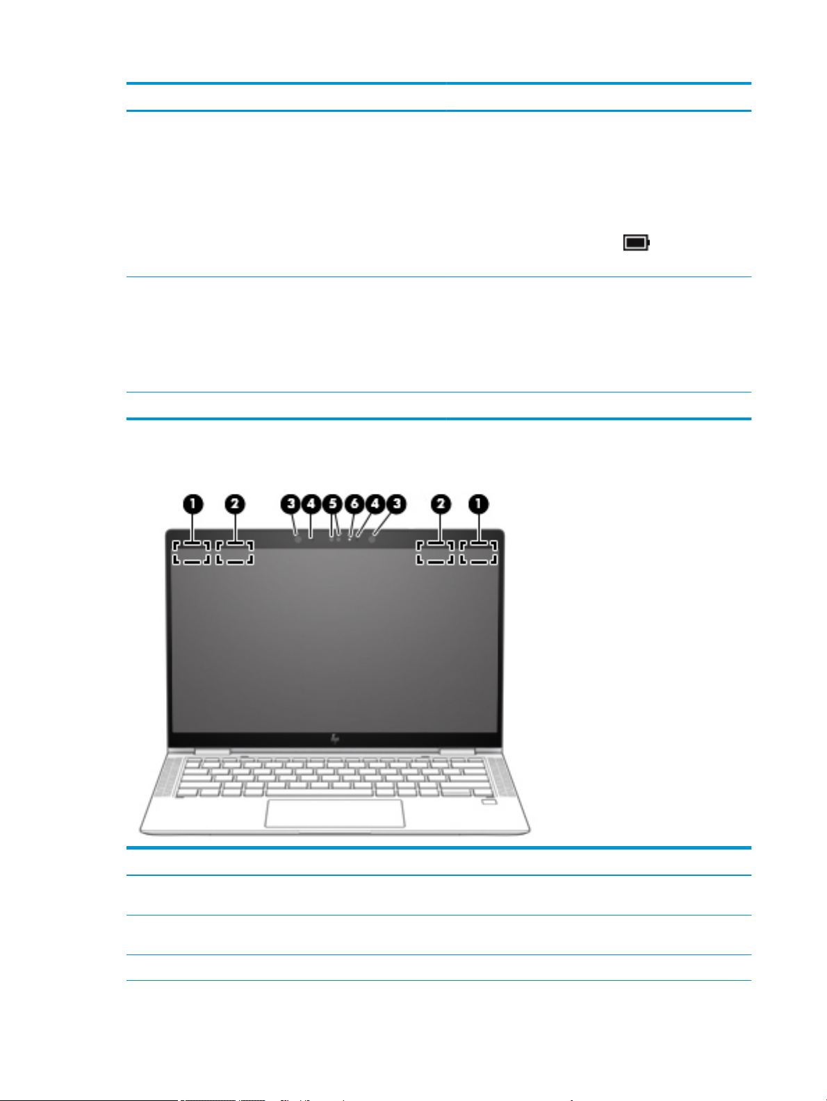
Display
Component Description
CAUTION: Pressing and holding down the power button results
in the loss of unsaved information.
If the computer has stopped responding and shutdown
procedures are ineective, press and hold the power button for at
least 5 seconds to turn o the computer.
To learn more about your power settings, see your power options.
▲ Right-click the Power meter icon and then select
Power Options.
(4) Power light ● On: The computer is on.
● Blinking: The computer is in the Sleep state, a power-saving
state. The computer shuts o power to the display and
other unneeded components.
● O: The computer is o or in Hibernation. Hibernation is a
power-saving state that uses the least amount of power.
(5) Nano SIM card slot Supports a wireless subscriber identity module (SIM) card.
Component Description
(1) WWAN antennas* (select products only) Send and receive wireless signals to communicate with wireless wide
(2) WLAN antennas* Send and receive wireless signals to communicate with wireless local
(3) Camera light(s) On: One or more cameras are in use.
6 Chapter 2 External component identication
area networks (WWANs).
area networks (WLANs).
Page 19

Component Description
(4) Internal microphones Record sound.
(5) Camera(s) Allow(s) you to video chat, record video, and record still images. Some
cameras also allow a facial recognition logon to Windows, instead of a
password logon.
NOTE: Camera functions vary depending on the camera hardware
and software installed on your product.
*The antennas are not visible from the outside of the computer. For optimal transmission, keep the areas immediately around the
antennas free from obstructions.
For wireless regulatory notices, see the section of the Regulatory, Safety, and Environmental Notices that applies to your country or region.
To access this guide:
▲ Select the Start button, select HP Help and Support, and then select HP Documentation.
‒ or –
▲ Select the Start button, select HP, and then select HP Documentation.
Display 7
Page 20
Keyboard area
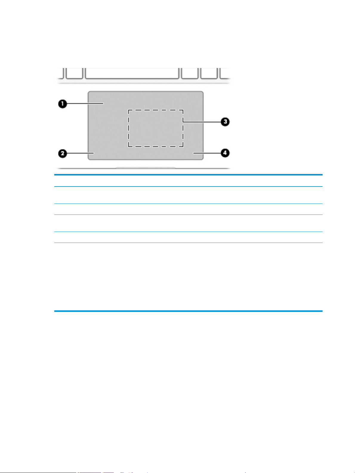
TouchPad
Component Description
(1) TouchPad zone Reads your nger gestures to move the pointer or activate items
(2) Left TouchPad button Functions like the left button on an external mouse.
on the screen.
(3) Near Field Communications (NFC) tapping area
and antenna* (select products only)
(4) Right TouchPad button Functions like the right button on an external mouse.
*The antenna is not visible from the outside of the computer. For optimal transmission, keep the area immediately around the antenna
free from obstructions.
For wireless regulatory notices, see the section of the Regulatory, Safety, and Environmental Notices that applies to your country or region.
To access this guide:
▲ Select the Start button, select HP Help and Support, and then select HP Documentation.
‒ or –
▲ Select the Start button, select HP, and then select HP Documentation.
Allows you to wirelessly share information when you tap it with
an NFC-enabled device.
8 Chapter 2 External component identication
Page 21

Lights
Component Description
(1) Caps lock light On: Caps lock is on, which switches the key input to all capital
letters.
(2) Mute light ● On: Computer sound is o.
● O: Computer sound is on.
(3) Microphone mute light ● On: Microphone is o.
● O: Microphone is on.
(4) Num lk light On: Num lock is on.
(5) Wireless light On: An integrated wireless device, such as a wireless local area
network (WLAN) device and/or a Bluetooth® device, is on.
NOTE: On some models, the wireless light is amber when all
wireless devices are o.
(6) Sharing or presenting light On: Sharing is on.
(7) Call answer light On: Call answer is on.
(8) Call end light On: Call end is on.
Keyboard area 9
Page 22
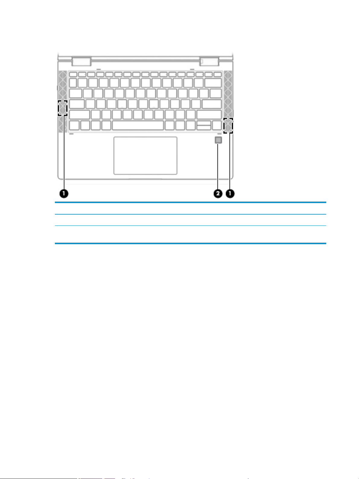
Speakers and ngerprint reader
Component Description
(1) Speakers Produce sound.
(2) Fingerprint reader Allows a ngerprint logon to Windows, instead of a password
logon.
10 Chapter 2 External component identication
Page 23
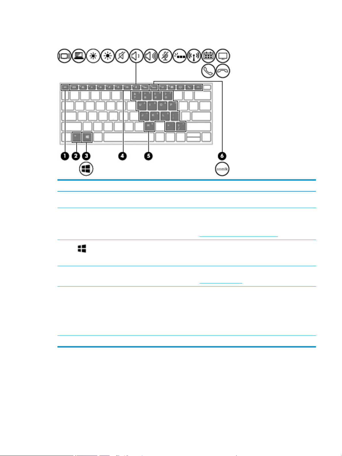
Special keys
Component Description
(1) esc key Displays system information when pressed in combination with
the fn key.
(2) fn key Executes frequently used system functions when pressed in
combination with another key. Such key combinations are called
hot keys.
See Hot keys (select products only) on page 14.
(3) Windows key Opens the Start menu.
NOTE: Pressing the Windows key again will close the Start
menu.
(4) Action keys Execute frequently used system functions.
See Action keys on page 12.
(5) Embedded numeric keypad A numeric keypad superimposed over the keyboard alphabet
keys. When fn+num lk is pressed, the keypad can be used like an
external numeric keypad. Each key on the keypad performs the
function indicated by the icon in the upper-right corner of the key.
NOTE: If the keypad function is active when the computer is
turned o, that function is reinstated when the computer is turned
back on.
(6) num lk key Turns the embedded numeric keypad on and o.
Keyboard area 11
Page 24
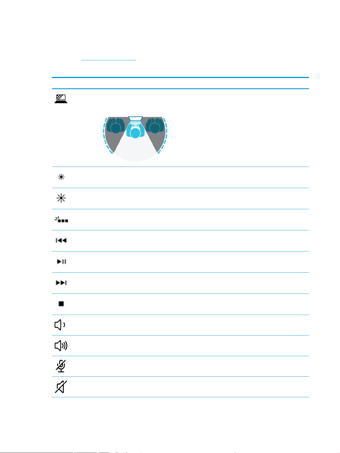
Action keys
An action key performs the function indicated by the icon on the key. To determine which keys are on your
product, see Special keys on page 11.
▲ To use an action key, press and hold the key.
Icon Description
Helps prevent side-angle viewing from onlookers. If needed, decrease or increase brightness for well-lit or
darker environments. Press the key again to turn o the privacy screen.
NOTE: To quickly turn on the highest privacy setting, press fn+p.
Decreases the screen brightness incrementally as long as you hold down the key.
Increases the screen brightness incrementally as long as you hold down the key.
Turns the keyboard backlight o or on.
NOTE: To conserve battery power, turn o this feature.
Plays the previous track of an audio CD or the previous section of a DVD or a Blu-ray Disc (BD).
Starts, pauses, or resumes playback of an audio CD, a DVD, or a BD.
Plays the next track of an audio CD or the next section of a DVD or a BD.
Stops audio or video playback of a CD, a DVD, or a BD.
Decreases speaker volume incrementally while you hold down the key.
Increases speaker volume incrementally while you hold down the key.
Mutes the microphone.
Mutes or restores speaker sound.
12 Chapter 2 External component identication
Page 25
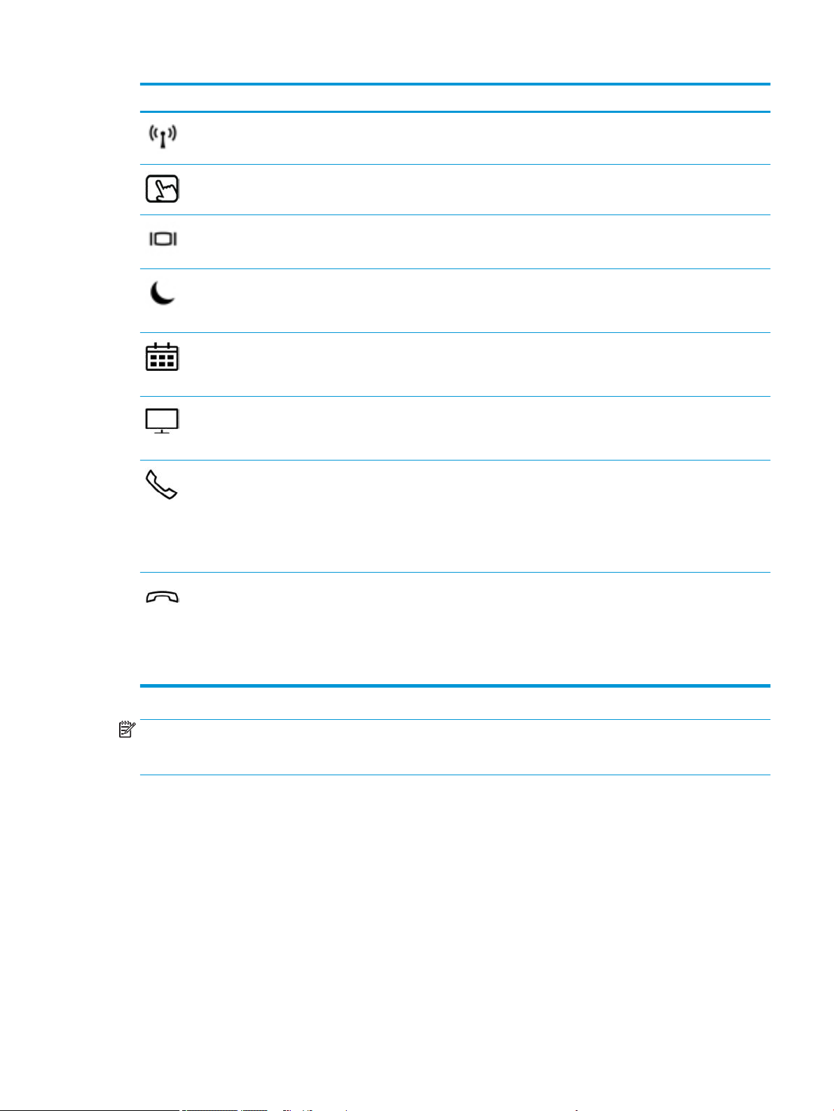
Icon Description
Turns the wireless feature on or o.
NOTE: A wireless network must be set up before a wireless connection is possible.
Turns the TouchPad and TouchPad light on and o.
Switches the screen image among display devices connected to the system. For example, if a monitor is
connected to the computer, repeatedly pressing the key alternates the screen image from computer display to
monitor display to simultaneous display on both the computer and the monitor.
Initiates Sleep, which saves your information in system memory. The display and other system components turn
o and power is conserved. To exit Sleep, briey press the power button.
CAUTION: To reduce the risk of information loss, save your work before initiating Sleep.
Provides quick access to your Skype for Business calendar.
NOTE: This feature requires Skype® for Business or Lync® 2013 running on Microsoft Exchange or Oce 365®
servers.
Turns the screen sharing function on or o.
NOTE: This feature requires Skype for Business or Lync 2013 running on Microsoft Exchange or Oce 365
servers.
● Answers a call.
● Starts a call during a 1-on-1 chat.
● Places a call on hold.
NOTE: This feature requires Skype for Business or Lync 2013 running on Microsoft Exchange or Oce 365
servers.
● Ends a call.
● Declines incoming calls.
● Ends screen sharing.
NOTE: This feature requires Skype for Business or Lync 2013 running on Microsoft Exchange or Oce 365
servers.
NOTE: The action key feature is enabled at the factory. You can disable this feature by pressing and holding the
fn key and the left shift key. The fn lock light will turn on. After you have disabled the action key feature, you can
still perform each function by pressing the fn key in combination with the appropriate action key.
Keyboard area 13
Page 26
Hot keys (select products only)
A hot key is the combination of the fn key and another key.
To use a hot key:
▲ Press the fn key, and then press one of the keys listed in the following table.
Key Description
E Turns on the insert function.
W Pauses the operation.
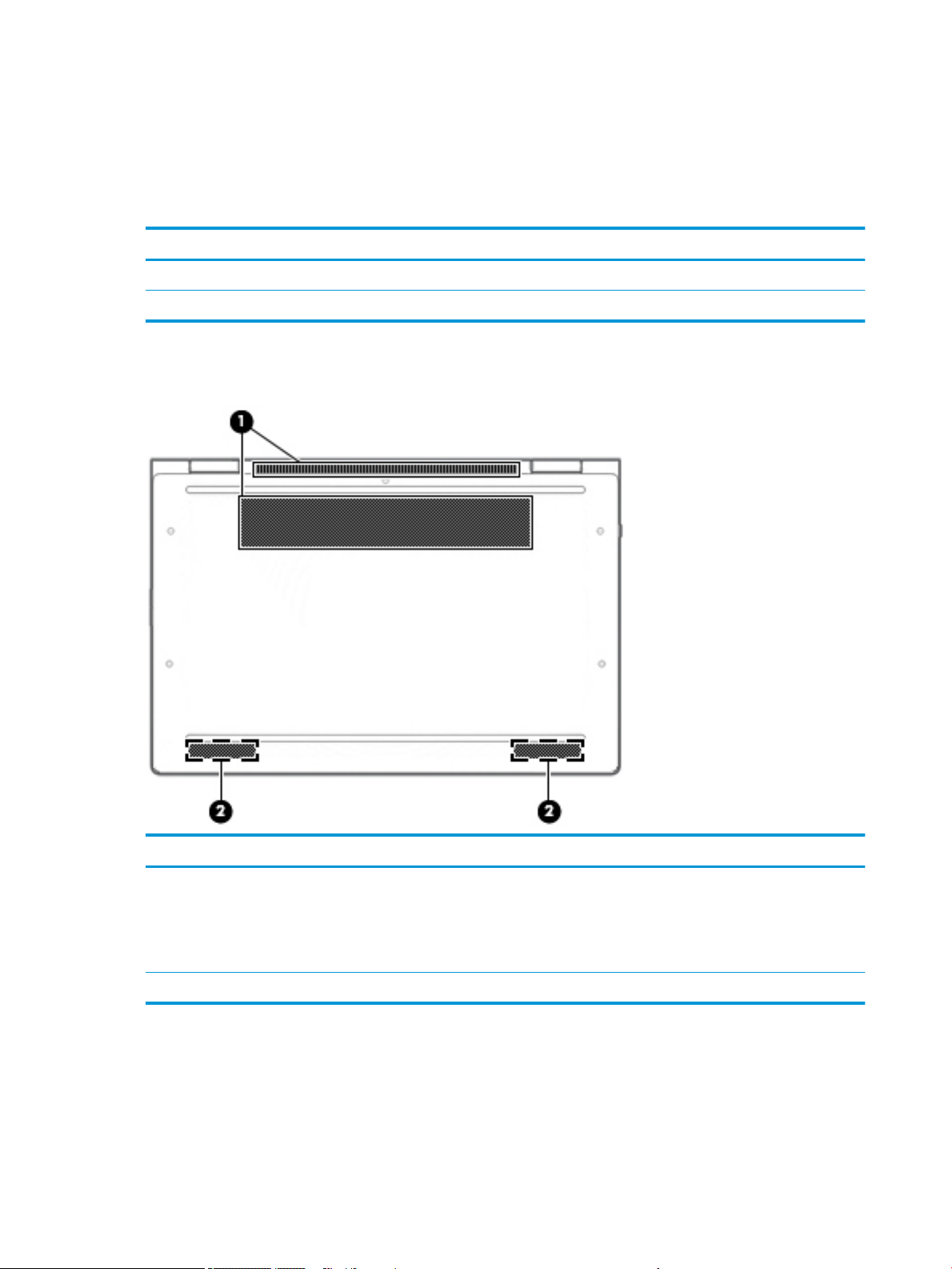
Bottom
Component Description
(1) Vents Enable airow to cool internal components.
(2) Speakers Produce sound.
14 Chapter 2 External component identication
NOTE: The computer fan starts up automatically to cool
internal components and prevent overheating. It is normal
for the internal fan to cycle on and o during routine
operation.
Page 27
Labels
The labels axed to the computer provide information you may need when you troubleshoot system problems
or travel internationally with the computer. Labels may be in paper form or imprinted on the product.
IMPORTANT: Check the following locations for the labels described in this section: the bottom of the computer,
inside the battery bay, under the service door, on the back of the display, or on the bottom of a tablet kickstand.
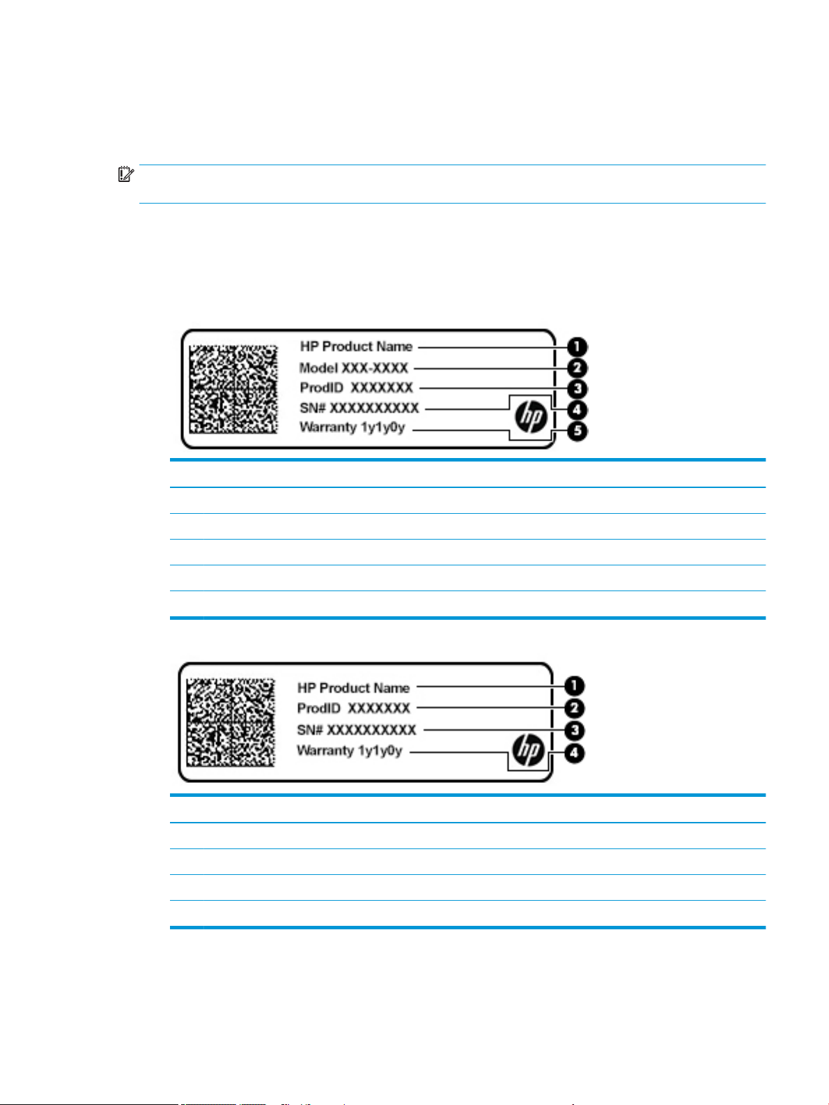
● Service label—Provides important information to identify your computer. When contacting support, you
may be asked for the serial number, the product number, or the model number. Locate this information
before you contact support.
Your service label will resemble one of the examples shown below. Refer to the illustration that most
closely matches the service label on your computer.
Component
(1) HP product name
(2) Model number
(3) Product ID
(4) Serial number
(5) Warranty period
Component
(1) HP product name
(2) Product ID
(3) Serial number
(4) Warranty period
● Regulatory label(s)—Provide(s) regulatory information about the computer.
● Wireless certication label(s)—Provide(s) information about optional wireless devices and the approval
markings for the countries or regions in which the devices have been approved for use.
Labels 15
Page 28

3 Illustrated parts catalog
Computer major components
NOTE: HP continually improves and changes product parts. For complete and current information on
supported parts for your computer, go to http://partsurfer.hp.com, select your country or region, and then follow
the on-screen instructions.
NOTE: Details about your computer, including model, serial number, product key, and length of warranty, are
on the service tag at the bottom of your computer. See Labels on page 15 for details.
16 Chapter 3 Illustrated parts catalog
Page 29
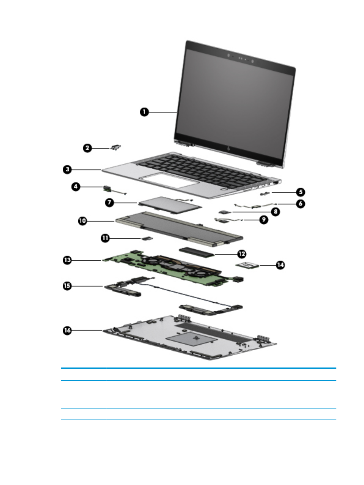
Item Component Spare part number
(1) Display assembly , touch screen
NOTE: Touch displays are only spared as full hinge-ups. Individual components are
not spared for touch screen displays.
LCD 13 FHD AG UWVA 400 nits touch L31868-001
LCD 13 FHD AG UWVA 700 nits touch (privacy) L31869-001
Computer major components 17
Page 30

Item Component Spare part number
LCD 13 FHD BV UWVA 400 nits touch L31870-001
LCD 13 FHD AG UWVA 700 nits touch (privacy) L31871-001
LCD 13 FHD BV UWVA 500 nits touch L31872-001
(2) Power button (spared with volume control board). Includes power button cable L31857-001
(3) Keyboard/top cover (includes keyboard cable, top cover shielding, and magnets)
For use in the United States L31882-001
For use in the United Kingdom L31882-031
For use in Germany L31882-041
For use in France L31882–051
For use in Italy L31882–061
For use in Spain L31882–071
For use in Denmark L31882–081
For use in Norway L31882–091
For use in Portugal L31882–131
For use in Turkey
For use in Turkey (F)
For use in Greece L31882–151
For use in Latin America L31882–161
For use in Saudi Arabia L31882–171
For use in Brazil L31882–201
For use in Hungary L31882–211
For use in Russia L31882–251
For use in Bulgaria L31882–261
For use in Romania L31882–271
For use in Thailand L31882–281
For use in Japan L31882–291
For use in Belgium L31882–A41
For use in Taiwain L31882–AB1
For use in Korea L31882–AD1
For use in Europe L31882–B31
L31882–141
L31882–541
For use in Sweden/Finland L31882–B71
For use in Slovakia L31882–BA1
For use in Hebrew L31882–BB1
For use in Switzerland L31882–BG1
18 Chapter 3 Illustrated parts catalog
Page 31

Item Component Spare part number
For use in India L31882–D61
For use in Canada (French/English) L31882–DB1
For use in Iceland L31882–DD1
For use in the Nordic region (English, Danish, Swedish, Finnish, and Norwegian) L31882–DH1
For use in Czechoslovakia and Slovenia L31882–FL1
For use in French Africa L31882–FP1
For use with products equipped with a privacy panel
For use in the United States L31883–001
For use in the United Kingdom L31883–031
For use in Germany L31883–041
For use in France L31883–051
For use in Italy L31883–061
For use in Spain L31883–071
For use in Denmark L31883–081
For use in Norway L31883–091
For use in Portugal L31883–131
For use in Turkey
For use in Turkey (F)
For use in Greece L31883–151
For use in Latin America L31883–161
For use in Saudi Arabia L31883–171
For use in Brazil L31883–201
For use in Hungary L31883–211
For use in Russia L31883–251
For use in Bulgaria L31883–261
For use in Thailand L31883–271
For use in Japan L31883–281
For use in Belgium L31883–A41
For use in Taiwan L31883–AB1
For use in Korea L31883–AD1
For use in Europe L31883–B31
L31883–141
L31883–541
For use in Sweden/Finland L31883–B71
For use in Slovenia L31883–BA1
For use in Israel L31883–BB1
Computer major components 19
Page 32

Item Component Spare part number
For use in Switzerland L31883–BG1
For use in India L31883–D61
For use in Canada (French/English) L31883–DB1
For use in Iceland L31883–DD1
For use in the Nordic region (English, Danish, Swedish, Finnish, and Norwegian) L31883–DH1
For use in Czechoslovakia and Slovenia L31883–FL1
For use in French Africa L31883–FP1
(4) Audio jack board L31858-001
(5) Volume control board (spared with power button) and cable L31857-001
(6) NFC module Included with TouchPad L31856-001
(7) TouchPad (includes NFC board cable) L31855-001
(8) Fingerprint reader bracket L31852-001
(9) Fingerprint reader board (includes double-sided adhesive and ngerprint reader
bracket)
(10) Battery L31852-001
(11) HDMI board bracket L31857-001
(12) Solid State Drive
128GB M2 SATA-3 TLC L31873–001
1TB PCIe NVMe TLC L31874–001
256GB PCIe NVMe TLC L31875–001
256GB PCIe NVMe Value L31876–001
2TB PCIe NVMe TLC L31877–001
360GB PCIe NVMe TLC L31878–001
512GB PCIe NVMe TLC L31879–001
512GB PCIe NVMe SED OPAL2 TLC L31880–001
256GB M2 SATA-3 SED OPAL2 TLC L31881–001
(13) System board (includes processor, graphics subsystem with UMA memory, fan/heat
sink, and replacement thermal material)
All system boards use the following part numbers:
xxxxxx-001: Windows 7 or non-Windows operating systems
L31852-001
xxxxxx-601: Windows 8.1 or Windows 10 operating system
i5-8250U, 8GB with fan/heatsink L31860-xx1
i5-8250U, 16GB with fan/heatsink L31861–xx1
i5-8350U, 8 GB with fan/heatsink L31862–xx1
i5-8350U, 16 GB with fan/heatsink L31863–xx1
20 Chapter 3 Illustrated parts catalog
Page 33

Item Component Spare part number
i7-8550U, 8 GB with fan/heatsink L31864–xx1
i7-8550U, 16 GB with fan/heatsink L31865–xx1
i7-8650U, 8 GB with fan/heatsink L31866–xx1
i7-8650U, 16 GB with fan/heatsink L31867–xx1
(14) WWAN module
HP It4132 LTE/HSPA+ 4G with GPS M.2 WWAN module
(15) Speaker assembly (includes cables, left and right speakers, and two rubber isolators) L31854-001
(16) Bottom cover L31851-001
Miscellaneous parts
Component Spare part number
AC adapter:
65 W USB-C adapter (non-PFC) – slim L04650—850
Cable kit L31853-001
Fan/heat sink L31859-001
Hardware kit L34181-001
Screw kit L34182-001
L29292-800
Miscellaneous parts 21
Page 34

4 Removal and replacement procedures
preliminary requirements
Tools required
You will need the following tools to complete the removal and replacement procedures:
● Flat-bladed screwdriver
● Magnetic screwdriver
● Phillips P0 and P1 screwdrivers
● Torx T8 screw driver
Service considerations
The following sections include some of the considerations that you must keep in mind during disassembly and
assembly procedures.
NOTE: As you remove each subassembly from the computer, place the subassembly (and all accompanying
screws) away from the work area to prevent damage.
Plastic parts
CAUTION: Using excessive force during disassembly and reassembly can damage plastic parts. Use care when
handling the plastic
Cables and connectors
CAUTION: When servicing the computer, be sure that cables are placed in their proper locations during the
reassembly process. Improper cable placement can damage the computer.
Cables must be handled with extreme care to avoid damage. Apply only the tension required to unseat or seat
the cables during removal and insertion. Handle cables by the connector whenever possible. In all cases, avoid
bending, twisting, or tearing cables. Be sure that cables are routed in such a way that they cannot be caught or
snagged by parts being removed or replaced. Handle ex cables with extreme care; these cables tear easily.
22 Chapter 4 Removal and replacement procedures preliminary requirements
Page 35

Drive handling
CAUTION: Drives are fragile components that must be handled with care. To prevent damage to the computer,
damage to a drive, or loss of information, observe these precautions:
Before removing or inserting a hard drive, shut down the computer. If you are unsure whether the computer is
o or in Hibernation, turn the computer on, and then shut it down through the operating system.
Before handling a drive, be sure that you are discharged of static electricity. While handling a drive, avoid
touching the connector.
Before removing an optical drive, be sure that a disc is not in the drive and be sure that the optical drive tray is
closed.
Handle drives on surfaces covered with at least one inch of shock-proof foam.
Avoid dropping drives from any height onto any surface.
After removing a hard drive or an optical drive, place it in a static-proof bag.
Avoid exposing an internal hard drive to products that have magnetic elds, such as monitors or speakers.
Avoid exposing a drive to temperature extremes or liquids.
If a drive must be mailed, place the drive in a bubble pack mailer or other suitable form of protective packaging
and label the package “FRAGILE.”
Electrostatic discharge damage
Electronic components are sensitive to electrostatic discharge (ESD). Circuitry design and structure determine
the degree of sensitivity. Networks built into many integrated circuits provide some protection, but in many
cases, ESD contains enough power to alter device parameters or melt silicon junctions.
A discharge of static electricity from a nger or other conductor can destroy static-sensitive devices or
microcircuitry. Even if the spark is neither felt nor heard, damage may have occurred.
An electronic device exposed to ESD may not be aected at all and can work perfectly throughout a normal
cycle. Or the device may function normally for a while, then degrade in the internal layers, reducing its life
expectancy.
CAUTION: To prevent damage to the tablet when you are removing or installing internal components, observe
these precautions:
Keep components in their electrostatic-safe containers until you are ready to install them.
Before touching an electronic component, discharge static electricity by using the guidelines described in this
section.
Avoid touching pins, leads, and circuitry. Handle electronic components as little as possible.
If you remove a component, place it in an electrostatic-safe container.
The following table shows how humidity aects the electrostatic voltage levels generated by dierent activities.
CAUTION: A product can be degraded by as little as 700 V.
Typical electrostatic voltage levels
Relative humidity
Event 10% 40% 55%
Walking across carpet 35,000 V 15,000 V 7,500 V
Electrostatic discharge damage 23
Page 36

Typical electrostatic voltage levels
Relative humidity
Event 10% 40% 55%
Walking across vinyl oor 12,000 V 5,000 V 3,000 V
Motions of bench worker 6,000 V 800 V 400 V
Removing DIPS from plastic tube 2,000 V 700 V 400 V
Removing DIPS from vinyl tray 11,500 V 4,000 V 2,000 V
Removing DIPS from Styrofoam 14,500 V 5,000 V 3,500 V
Removing bubble pack from PCB 26,500 V 20,000 V 7,000 V
Packing PCBs in foam-lined box 21,000 V 11,000 V 5,000 V
Packaging and transporting guidelines
Follow these grounding guidelines when packaging and transporting equipment:
● To avoid hand contact, transport products in static-safe tubes, bags, or boxes.
● Protect ESD-sensitive parts and assemblies with conductive or approved containers or packaging.
● Keep ESD-sensitive parts in their containers until the parts arrive at static-free workstations.
● Place items on a grounded surface before removing items from their containers.
● Always be properly grounded when touching a component or assembly.
● Store reusable ESD-sensitive parts from assemblies in protective packaging or nonconductive foam.
● Use transporters and conveyors made of antistatic belts and roller bushings. Be sure that mechanized
equipment used for moving materials is wired to ground and that proper materials are selected to avoid
static charging. When grounding is not possible, use an ionizer to dissipate electric charges.
Workstation guidelines
Follow these grounding workstation guidelines:
● Cover the workstation with approved static-shielding material.
● Use a wrist strap connected to a properly grounded work surface and use properly grounded tools and
equipment.
● Use conductive eld service tools, such as cutters, screw drivers, and vacuums.
● When xtures must directly contact dissipative surfaces, use xtures made only of static-safe materials.
● Keep the work area free of nonconductive materials, such as ordinary plastic assembly aids and Styrofoam.
● Handle ESD-sensitive components, parts, and assemblies by the case or PCM laminate. Handle these items
only at static-free workstations.
● Avoid contact with pins, leads, or circuitry.
● Turn o power and input signals before inserting or removing connectors or test equipment.
24 Chapter 4 Removal and replacement procedures preliminary requirements
Page 37

Equipment guidelines
Grounding equipment must include either a wrist strap or a foot strap at a grounded workstation.
● When seated, wear a wrist strap connected to a grounded system. Wrist straps are exible straps with a
minimum of one megohm ±10% resistance in the ground cords. To provide proper ground, wear a strap
snugly against the skin at all times. On grounded mats with banana-plug connectors, use alligator clips to
connect a wrist strap.
● When standing, use foot straps and a grounded oor mat. Foot straps (heel, toe, or boot straps) can be
used at standing workstations and are compatible with most types of shoes or boots. On conductive oors
or dissipative oor mats, use foot straps on both feet with a minimum of one megohm resistance between
the operator and ground. To be eective, the conductive must be worn in contact with the skin.
The following grounding equipment is recommended to prevent electrostatic damage:
● Antistatic tape
● Antistatic smocks, aprons, and sleeve protectors
● Conductive bins and other assembly or soldering aids
● Nonconductive foam
● Conductive tabletop workstations with ground cords of one megohm resistance
● Static-dissipative tables or oor mats with hard ties to the ground
● Field service kits
● Static awareness labels
● Material-handling packages
● Nonconductive plastic bags, tubes, or boxes
● Metal tote boxes
● Electrostatic voltage levels and protective materials
The following table lists the shielding protection provided by antistatic bags and oor mats.
Material Use Voltage protection level
Antistatic plastics Bags 1,500 V
Carbon-loaded plastic Floor mats 7,500 V
Metallized laminate Floor mats 5,000 V
Equipment guidelines 25
Page 38

5 Removal and replacement procedures for
authorized service provider parts
CAUTION: Components described in this chapter should be accessed only by an authorized service provider.
Accessing these parts can damage the computer or void the warranty.
CAUTION: This computer does not have user-replaceable parts. Only HP authorized service providers should
perform the removal and replacement procedures described here. Accessing the internal part could damage the
computer or void the warranty.
Component replacement procedures
NOTE: Details about your computer, including model, serial number, product key, and length of warranty, are
on the service tag at the bottom of your computer. See for details.
NOTE: HP continually improves and changes product parts. For complete and current information on
supported parts for your computer, go to http://partsurfer.hp.com, select your country or region, and then follow
the on-screen instructions.
There are as many as xx screws that must be removed, replaced, and/or loosened when servicing the parts
described in this chapter. Make special note of each screw size and location during removal and replacement.
Bottom cover
Description Spare part number
Bottom cover for use in all models L31851-001
Before removing the bottom cover, follow these steps:
1. Turn o the computer. If you are unsure whether the computer is o or in Hibernation, turn the computer
2. Disconnect the power from the computer by unplugging the power cord from the computer.
3. Disconnect all external devices from the computer.
Remove the bottom cover:
1. Remove the four Torx T8M2.0×4.3 screws (1) and loosen the captive screw (2) that secures the bottom
on, and then shut it down through the operating system.
cover to the computer.
26 Chapter 5 Removal and replacement procedures for authorized service provider parts
Page 39

Battery
2. Remove the bottom cover (3).
Reverse the removal procedures to install the bottom cover.
Description Spare part number
4-cell, 49-Whr, 6.4-Ah, Li ion battery 915191-855
Before disassembling the computer, follow these steps:
1. Turn o the computer. If you are unsure whether the computer is o or in Hibernation, turn the computer
on, and then shut it down through the operating system.
2. Disconnect the power from the computer by unplugging the power cord from the computer.
3. Disconnect all external devices from the computer.
4. Remove the bottom cover (see Bottom cover on page 26).
Remove the battery:
1. Disconnect the battery cable from the system board (1).
2. Remove the four Phillips screws (2) that secure the battery to the computer.
Component replacement procedures 27
Page 40

3. Remove the Phillips broadhead screw, and lift the battery out of the computer (3).
28 Chapter 5 Removal and replacement procedures for authorized service provider parts
Page 41

Solid State drive
Description Spare part number
Solid State drive (SSD)
128 GB, M2 SATA-3 TLC L31873-001
256 GB, PCIe NVMe TLC L31875-001
256 GB, PCIe NVMe Value L31881-001
256 GB, SED OPAL2 TLC L31876-001
512 GB, PCIe Gen 3 x 4 NVMe SS TLC L31878-001
512 GB, PCIe Gen 3 x 4 NVMe SS TLC L31879-001
1 TB, PCIe NVMe TLC L31874-001
2TB, PCIe NVMe TLC L31877–001
Before removing the SSD, follow these steps:
1. Turn o the computer. If you are unsure whether the computer is o or in Hibernation, turn the computer
on, and then shut it down through the operating system.
2. Disconnect the power from the computer by unplugging the power cord from the computer.
3. Disconnect all external devices from the computer.
4. Remove the bottom cover (see Bottom cover on page 26).
5. Remove the battery. (see Battery on page 27).
Remove the SSD:
1. Remove the Mylar strip that covers the SSD .
Component replacement procedures 29
Page 42

2. Remove the Phillips PM2.0×1.8 screw (1) that secures the drive to the system board.
3. Remove the drive (2) by pulling it away from the connector.
NOTE: SSDs are designed with notches to prevent incorrect insertion.
Reverse this procedure to reassemble and install the SSD.
30 Chapter 5 Removal and replacement procedures for authorized service provider parts
Page 43

System board
NOTE: The system board spare part kit includes replacement thermal material.
All system boards use the following part numbers:
xxxxxx-001: Windows 7 or non-Windows operating systems
xxxxxx-601: Windows 8.1 or Windows 10 operating system
Description Spare part number
Equipped with Intel Core i5-8250U processor 8 GB L31860-xxx
Equipped with Intel Core i5-8250U processor 16GB L31861-xxx
Equipped with Intel Core i5-8350U processor 8 GB L31862-xxx
Equipped with Intel Core i5-8350U processor 8 GB L31863-xxx
Equipped with Intel Core i7-8550U processor 16 GB L31864-xxx
Equipped with Intel Core i7-8550U processor 8 GB L31864-xxx
Equipped with Intel Core i7-8650U processor 8 GB L31865–xxx
Equipped with Intel Core i7-8650U processor 8 GB L31865–xxx
Before removing the system board, follow these steps:
1. Turn o the computer. If you are unsure whether the computer is o or in Hibernation, turn the computer
on, and then shut it down through the operating system.
2. Disconnect the power from the computer by unplugging the power cord from the computer.
3. Disconnect all external devices from the computer.
4. Remove the bottom cover (see Bottom cover on page 26).
5. Remove the battery (see Battery on page 27).
6. Remove the SSD (see Solid State drive on page 29).
Remove the system board:
1. Disconnect the following cables:
(1): Audio
(2): Power button
(3): Speaker
(4): Panel
(5): TouchPad
(6): Keyboard back light
(7): NFC module
(8): Keyboard
(9): Fingerprint reader
Component replacement procedures 31
Page 44

2. Remove the SIM card insert (1), and then remove the 2 long screws (2).
3. Remove the HDMI module (3).
4. Remove the eight Phillips screws (4) that secure the system board to the computer.
5. Pull the system board up (5) and away from the computer (6), making sure the connectors on the side of
the board are clear of the computer.
CAUTION: To avoid damaging or breaking the system board, use two hands when removing the board. Do
not lift up on the narrow end of the board.
32 Chapter 5 Removal and replacement procedures for authorized service provider parts
Page 45

Reverse this procedure to install the system board.
Component replacement procedures 33
Page 46

Display assembly
This section describes removing components that require you to completely remove the display panel. Individual
components are not spared for the display assembly.
Before removing the display assembly, follow these steps:
1. Turn o the computer. If you are unsure whether the computer is o or in Hibernation, turn the computer
on, and then shut it down through the operating system.
2. Disconnect the power from the computer by unplugging the power cord from the computer.
3. Disconnect all external devices from the computer.
4. Remove the bottom cover (see Bottom cover on page 26).
Remove the display assembly:
1. Open the computer completely and fold the display under the base enclosure.
2. Remove the six Phillips screws (1) that secure the left and right brackets, and open the display slightly.
3. Slide the display slightly toward the front (2) to disengage the display from the computer and remove the
display (3).
Reverse this procedure to reinstall the display assembly.
34 Chapter 5 Removal and replacement procedures for authorized service provider parts
Page 47

Audio jack board
Description Spare part number
Audio jack board L31858-001
IMPORTANT: Make special note of each screw and screw lock size and location during removal and replacement
Before removing the audio module, follow these steps:
1. Shut down the computer.
2. Disconnect all external devices connected to the computer.
3. Disconnect the power from the computer by rst unplugging the power cord from the AC outlet and then
unplugging the AC adapter from the computer.
4. Remove the battery (see Battery on page 27).
Remove the Audio jack board:
1. Disconnect the audio jack board cable from the system board (1).
2. Remove the Phillips screw (2), and then remove the audio jack board (3).
Reverse this procedure to install the audio jack board.
Component replacement procedures 35
Page 48

Power module
Description Spare part number
Power module L31857-001
IMPORTANT: Make special note of each screw and screw lock size and location during removal and replacement
Before removing the power module, follow these steps:
1. Shut down the computer.
2. Disconnect all external devices connected to the computer.
3. Disconnect the power from the computer by rst unplugging the power cord from the AC outlet and then
unplugging the AC adapter from the computer.
4. Remove the battery (see Battery on page 27).
Remove the Power module:
1. Disconnect the Power module (1).
2. Remove the two Phillips screws (2), and then remove the Power module.
Reverse this procedure to install the power module.
36 Chapter 5 Removal and replacement procedures for authorized service provider parts
Page 49

Speaker assembly
Description Spare part number
Speaker assembly contains four speakers, with foam/rubber tape L31854-001
Before removing the speaker assembly, follow these steps:
1. Turn o the computer. If you are unsure whether the computer is o or in Hibernation, turn the computer
on, and then shut it down through the operating system.
2. Disconnect the power from the computer by unplugging the power cord from the computer.
3. Disconnect all external devices from the computer.
4. Remove the bottom cover (see Bottom cover on page 26).
5. Remove the battery (see Battery on page 27).
Remove the speaker assembly:
1. Disconnect the speaker cables from the system board (1).
2. Remove the six screws securing the speakers (2).
3. Remove the plastic tape holding the speaker cable (3), and then remove the wiring (4).
4. Remove the left and right speakers (5).
Reverse this procedure to install the speaker.
Component replacement procedures 37
Page 50

Fingerprint reader board
Description Spare part number
Fingerprint reader board (includes cable) L31852-001
Before removing the ngerprint reader board, follow these steps:
1. Turn o the computer. If you are unsure whether the computer is o or in Hibernation, turn the computer
on, and then shut it down through the operating system.
2. Disconnect the power from the computer by unplugging the power cord from the computer.
3. Disconnect all external devices from the computer.
4. Remove the bottom cover (see Bottom cover on page 26).
5. Remove the battery (see Battery on page 27).
Remove the ngerprint reader board:
1. Disconnect the ngerprint reader board from the system board (1).
2. Remove the Phillips screw (2) that secures the assembly to the computer.
3. Lift the bracket up at the screw end and remove the ngerprint bracket (3).
4. Remove the ngerprint reader board and cable from the computer (4).
Reverse this procedure to install the ngerprint reader board.
38 Chapter 5 Removal and replacement procedures for authorized service provider parts
Page 51

TouchPad
Before removing the TouchPad, follow these steps:
1. Turn o the computer. If you are unsure whether the computer is o or in Hibernation, turn the computer
2. Disconnect the power from the computer by unplugging the power cord from the computer.
3. Disconnect all external devices from the computer.
4. Remove the bottom cover (see Bottom cover on page 26).
5. Remove the battery (see Battery on page 27).
Remove the TouchPad:
1. Disconnect the TouchPad cable (1) from the system board.
2. Remove the six Phillips screws (2) that secure the TouchPad to the computer, and then lift the TouchPad
Description Spare part number
TouchPad L31855-001
TouchPad with NFC module (includes antenna and tape) L31856-001
on, and then shut it down through the operating system.
from the computer (3).
Reverse the removal procedures to install the TouchPad.
Component replacement procedures 39
Page 52

NFC board
Description Spare part number
NFC board
NOTE: The NFC board spare part kit does not include the NFC board cable. The NFC board cable is included in
the Cable Kit, spare part number.
L31856-001
IMPORTANT: Make special note of each screw and screw lock size and location during removal and replacement
Before removing the NFC board, follow these steps:
1. Shut down the computer.
2. Disconnect all external devices connected to the computer.
3. Disconnect the power from the computer by rst unplugging the power cord from the AC outlet and then
unplugging the AC adapter from the computer.
4. Disconnect all external devices from the computer.
5. Remove the bottom cover.
6. Remove the battery (see Battery on page 27).
Remove the NFC board:
1. Release the ZIF connector (1) to which the NFC board cable is attached, and then disconnect the NFC board
cable from the card reader board.
2. Release the grounding tape (2) that secures the NFC board cable to the NFC board.
3. Release the ZIF connector (3) to which the NFC board cable is attached, and then disconnect the NFC board
cable from the NFC board.
40 Chapter 5 Removal and replacement procedures for authorized service provider parts
Page 53

4. Detach the NFC board (4) from the keyboard/top cover. (The NFC board is attached to the keyboard/top
cover with double-side adhesive.)
5. Remove the NFC board.
Reverse this procedure to install the NFC board.
Component replacement procedures 41
Page 54

WWAN module
Description Spare part number
WWAN module
HP It4132 LTE/HSPA+ 4G with GPS M.2 WWAN module
L29292–800
CAUTION: To prevent an unresponsive system, replace the wireless board only with a wireless board
authorized for use in the computer by the governmental agency that regulates wireless devices in your country
or region. If you replace the board and then receive a warning message, remove the board to restore device
functionality, and then contact technical support.
IMPORTANT: Make special note of each screw and screw lock size and location during removal and replacement
Before removing the WWAN module, follow these steps:
1. Shut down the computer.
2. Disconnect all external devices connected to the computer.
3. Disconnect the power from the computer by rst unplugging the power cord from the AC outlet and then
unplugging the AC adapter from the computer.
4. Remove the battery (see Battery on page 27), and then remove the following components:
Remove the WWAN module:
NOTE: In order to remove or replace the WWAN module, you may need to rst remove the Mylar strip that may
block access to the WWAN module.
1. Disconnect the WWAN antenna cables (1) from the terminals on the WWAN module.
42 Chapter 5 Removal and replacement procedures for authorized service provider parts
Page 55

NOTE: The #5/red WWAN antenna cable connects to the WWAN module #5/Main terminal. The #6/blue
WWAN antenna cable connects to the WWAN module #6/Aux terminal.
2. Remove the Phillips PM2.0×2.4 screw (2) that secures the WWAN module to the system board. (The WWAN
module tilts up.)
3. Remove the WWAN module (3) by pulling the board away from the slot at an angle.
NOTE: If the WWAN antenna is not connected to the terminal on the WWAN module, a protective sleeve must
be installed on the antenna connector, as shown in the following illustration.
Reverse this procedure to install the WWAN module.
Component replacement procedures 43
Page 56

6 Troubleshooting guide
This chapter is primarily focused on troubleshooting HP Mobile Workstations and HP Notebooks. The information
is provided so that you can solve problems yourself or at least narrow down what may be causing the
problem. Based on some of the most common symptoms, this chapter helps to identify logical steps and
available resources or tools for resolving an issue. HP recommends that you follow the instructions carefully,
observe safety precautions, and note any observations or results. Capturing this information may help identify
and resolve the problem faster.
WARNING! To reduce the risk of electric shock or damage to the equipment:
● Do not disable the power cord grounding plug. The grounding plug is an important safety feature.
● Plug the power cord into a grounded (earthed) outlet that is easily accessible at all times.
● Disconnect power from the equipment by unplugging the power cord from the AC outlet.
● Before disassembling notebooks, always disconnect power and remove the battery.
CAUTION: Static electricity can damage the electronic components of the computer. To prevent damage to the
computer, carefully observe the electrostatic discharge precautions.
● Discharge static electricity by briey touching a grounded metal object before you begin.
● Work on a static-free mat.
● Wear a static strap to ensure that any accumulated electrostatic charge is discharged from your body to
the ground.
● Create a common ground for the equipment you are working on by connecting the static-free mat, static
strap, and peripheral units to that piece of equipment.
● Refer to the Electrostatic Discharge Section of the Maintenance & Service Guide for more information.
CAUTION: The computer includes customer self-repair parts and parts that should only be accessed by an
authorized service provider. See the chapter titled "Removal and replacement procedures for Customer SelfRepair parts," for details. Accessing parts described in the chapter titled "Removal and replacement procedures
for authorized service provider only parts" can damage the computer or void the computer warranty.
44 Chapter 6 Troubleshooting guide
Page 57

Resources
HP Resource Tool Description Link
HP Elite Support Provides live HP Premium support (available 24/7) to
Elite computers.
HP Support Center Provides important support, such as warranty, support
cases, drivers, Customer Advisories, Customer and
Security Bulletins, and Product Change Notices.
HP Troubleshooting Support page Provides troubleshooting information for your specic
HP computer.
Subscribers Choice Allows you to sign up for HP product updates. http://www8.hp.com/us/en/subscribe/
HP Support Forums Provide discussions about HP products and issues. http://h30434.www3.hp.com/psg/
Service Access Workbench (SAW)
(Available for technicians and
Business Partners only)
Vendors’ web sites Provide additional information for associated
Provides navigable content intended for use by
internal and outsourced call center sta and can be a
resource for support and product division
professionals.
components such as Intel (processor, WLAN), Microsoft
(Windows 7/8/10), AMD/NVidia (GPU), and so on.
General troubleshooting steps
http://www8.hp.com/us/en/ads/eliteproducts/overview.html
http://h20565.www2.hp.com/portal/site/
hpsc
http://www8.hp.com/us/en/
troubleshooting.html
http://sawpro.atlanta.hp.com/km/saw/
home.do
http://www.intel.com/content/www/us/en/
homepage.html
http://www.amd.com
http://www.nvidia.com
A basic logic should be used when troubleshooting computer issues. This section will help you become familiar
with troubleshooting methodology and eciently resolve problems. Proceed through the steps in the following
table until the issue is resolved, and then move on to the next step that is relevant to the issue. For example, if
you resolve a memory issue using the HP PC Diagnostics (UEFI) tool in step 6, you can then move on to step 10
to reseat the memory into its memory slot.
NOTE: General troubleshooting steps do not have to be followed in a specic order if an issue does not apply.
Table 6-1 Troubleshooting methodology and general troubleshooting steps
Identify issue Analyze issue Resolve issue Verify solution
1. Understand the issue
on page 46
2. Examine the environment
on page 48
3. Perform a visual inspection
of hardware on page 49
4. Update BIOS and drivers
on page 49
5. Remove or uninstall recently
added hardware, software
on page 49
6. HP Hardware Diagnostics and
Tools on page 50
7. Status lights, blinking light
codes, troubleshooting lights, and
POST error messages on page 54
8. Hard reset on page 57
9. Soft reset (Default Settings) on page 58
10. Reseat cables and connections
on page 58
11. Test with minimum conguration
on page 59
12. Test with veried working conguration
(hardware and/or operating system)
on page 60
13. Replace the system board on page 60
Verify solution
on page 61
Resources 45
Page 58

Identify the issue
1. Understand the issue
It is important to understand the issue that occurred, including related symptoms. It helps to understand the
basic computer boot-up sequence as well as the failure itself. The boot-up sequence and associated failures are
described below.
Boot up sequence
The computer performs several steps after you press the power button or restart the computer.
It is important to understand where in the boot-up sequence the symptoms occur. The following table lists the
phases of the boot-up sequence and explains the symptoms that may occur in each phase. For example, a blue
screen error (BSOD) often occurs during the performance phase.
Table 6-2 Boot-up sequence
Item Procedure
Power-on After power button is pressed, the computer boots after all internal power rails (i.e., 5V, 3.3V) are stable.
Conrm that power lights are on fan is spinning.
Next step: If the computer experiences a power-on issue, see “Verify Power Good (Troubleshooting) lights” in No
Power on page 63.
Common issues: all lights are o; troubleshooting lights are on; does not boot; video is absent.
POST (UEFI/BIOS) Power-On Self-Test (POST) veries that hardware components (processor, hard drive, memory, etc.) are
Performance
(operating system)
Failure classication
Failure classication is a breakdown of dierent types of failures and symptoms that could occur during the
boot-up sequence. Table 3 and table 4 represent the failure classication for common notebook failures.
Table 3 categorizes failures by the boot-up sequence.
1. Power-on: Common issues are No Power, Recycle/Reboot, etc.
2. POST: Common issues are No Boot (have power), Light Flash or Diagnostics Error.
3. Performance: Common issues are Intermittent Loss of Power, Blue Screen, Hang, etc. In many cases, issues
may be identied and associated with a particular hardware (i.e., display, storage).
Table 4 categorizes failures by hardware.
functional. When POST is complete, the HP logo displays briey and then disappears.
If there are errors, the computer may exhibit blinking lights and POST error messages
Common issues: lights blink, error message appears, hangs.
System boots to operating system, and Windows logo screen appears.
Common issues: hangs (lock up/freezes), blue screen, video distorted, driver conict, slow performance, display
issue (dead pixel), I/O issue (no speaker sound), wireless/audio unavailable, noise.
See Analyze the issue on page 49 table below for detailed troubleshooting information).
4. Display
5. I/O devices (Input/Output)
46 Chapter 6 Troubleshooting guide
Page 59

6. Storage
7. Mechanical
A single symptom can be listed under dierent groups. For example, No Video can belong to (1) Power-on or (4)
Display; but Flickering when powered should be listed in (4) Display. Or, in another example, a blue screen can be
caused by a driver conict in Performance (4), but it can also be caused by a defective hard drive under (6)
Storage. Therefore, failures that share similar symptoms are noted.
If possible, make a record of the failure symptom, the phase of the boot-up sequence where the failure occurs,
and the most likely location in the failure tree (Table 6-3 Failure classication by boot-up sequence on page 47
and Table 6-4 Failure classication by hardware devices and mechanical on page 48). This will help isolate the
issue and indicate the next steps. For example, when the computer is running the operating system, it may
experience an issue with (4) Display, (5) I/O devices (keyboard, wireless, and so on), (6) Storage, or (7) Mechanical
components (stuck buttons, thermal shutdown, and so on).
NOTE: “Uncategorized” is used if an issue found is not listed. For example, Bluetooth is oered on certain
hardware congurations; therefore, a Bluetooth issue can be classied under “I/O Device” if needed.
Failure classication by boot-up sequence
Table 6-3 Failure classication by boot-up sequence
1. Power-on 2. POST 3. Performance
1. No Power on page 63
2. Intermittent power-on, shutdown,
reboot on page 65
3. AC adapter issue on page 66
4. Battery not recognized, not charging
on page 66
5. Battery discharges too fast
on page 68
6. Burnt smell on page 68
a,b,c
similar symptoms
a
1. No video (with power) on page 69
2. Blinking lights on page 70
3. Diagnostics error messages
on page 70
4. BIOS password on page 72
1. Intermittent shutdown on page 73
2. Blue screen (BSOD) error on page 98
3. Freeze at Windows Logo (hang/lockup)
on page 76
4. Electromagnetic Interference (EMI)
on page 77
5. No wake up on page 78
6. Unresponsive on page 79
7. Slow performance on page 79
8. HP Smart Adapter warning message
on page 80
9. Incorrect time and date on page 80
a
b
c
General troubleshooting steps 47
Page 60

Failure classication by hardware devices and mechanical
Table 6-4 Failure classication by hardware devices and mechanical
4. Display 5. I/O devices 6. Storage 7. Mechanical
1. Display anomalies
on page 81
2. Dead pixel on page 83
3. No video (internal)
on page 83
4. No video (external)
on page 84
5. DisplayPort/VGA
on page 84
6. HDMI on page 84
7. No or bad external video
via docking on page 85
8. Incorrect or missing color/
distorted image
on page 85
9. Touch screen on page 86
b,c,d
similar symptoms
d
d
1. Keyboard on page 87
2. Keyboard point stick
on page 88
3. Keyboard backlight
on page 88
4. TouchPad on page 89
5. Network Connectivity
Ethernet (RJ-45 jack)
on page 89
6. Network connectivity
wireless (WLAN)
on page 90
7. WWAN on page 91
8. USB on page 92
9. Smart card reader
on page 93
10. Speaker, headphone audio issues on page 94
11. Thunderbolt (TB)
on page 95
1. Hard drive/solid-state
drive not recognized
on page 97
2. No boot to operating
system (no read/write
error) on page 97
3. Read-write error
on page 98
4. Slow performance
on page 79
5. Blue screen (BSOD) error
on page 98
6. Noisy hard drive
on page 99
c
b
1. Fan error message - 90B
on page 100
2. Noise (sound) on page 101
3. Fan runs constantly
on page 102
4. HP Thermal Monitor
on page 53
5. Stuck power button
on page 103
2. Examine the environment
It is important to examine the computer’s environment. If you can quickly identify the cause of the issue, fewer
resolution steps may be needed. Perform the following environment inspections:
● Check all cables and connections to be sure that there are no loose connections.
● Conrm that power sources are good, such as wall power type/adapter (110V/220V ac), power strip. Test
with a veried working AC outlet.
● Check for compatibility issues between the computer and third-party devices, peripherals, noncertied
devices, incompatible hardware (i.e., Mac OS device). Incompatibility can result in blue screen errors,
improper operation, and so on.
● Isolate the computer from sources of electromagnetic interference (EMI), such as cell phones, 2-way
radios, oor mats, fans (and other electronic motors). EMI may contribute to a display freeze issue or lockup.
48 Chapter 6 Troubleshooting guide
Page 61

3. Perform a visual inspection of hardware
It is important to do a visual inspection of the hardware itself. Perform physical inspection of the computer:
● Look for abnormalities such as a cracked display, dented battery, broken latches for battery bay, keyboard
key caps popped out, dust over connectors, liquid spill over keyboard, etc.
● Look for signs of drop, movement, or vibration that may cause internal and external loose connections.
4. Update BIOS and drivers
IMPORTANT: Whenever possible, update to the latest BIOS, rmware, and drivers before troubleshooting.
Note that some customer company policies prohibit updates. Check your company policy before taking action.
The updates may include xes for your computer issues, and they may also enhance system performance. HP
continually improves the update process to make it easier. The BIOS update can be done locally through a
manual process, through an automatic installation, or through a remote installation on multiple units.
Manually updating BIOS and drivers
● See the Computer Setup chapters to manually update BIOS and drivers.
● Refer to specic BIOS update installation instructions that accompany the download.
Remotely deploying BIOS and drivers
Instead of manually searching for and downloading each SoftPaq, users and IT personnel can use two tools to
identify and download all appropriate SoftPaqs for the selected HP models.
● HP SoftPaq Download Manager (SDM) is a software tool designed to streamline the download, extraction,
and installation process of SoftPaqs, including BIOS and drivers.
● HP System Software Manager (SSM) is a software tool designed to simplify the deployment of SoftPaqs to
HP computers.
Analyze the issue
5. Remove or uninstall recently added hardware, software
HP has designed this computer and validated it using a full-range hardware and software qualication matrix. If
an issue appears to have started recently, it may be related to the recent addition of hardware or software. A
good method to determine the root cause is to remove recently added components or uninstall applications one
at a time and restart the computer when necessary.
IMPORTANT: After you have completed the process of uninstalling hardware or software and are ready to
reinstall, when installing a new device be sure that it is seated properly and all cables are correctly connected.
After installing the device, restart the computer and make sure the new device is powered on. In addition, if the
new device is a root cause of a problem, it could cause a conict in drivers or incompatibility issues with other
programs installed. For any new hardware you have added, be sure to install the latest drivers available from the
device vendor website.
General troubleshooting steps 49
Page 62

6. HP Hardware Diagnostics and Tools
HP oers dierent diagnostics and tools to diagnose hardware failure. This section describes how to use some of
these tools. Make sure to check for the latest versions before use.
HP PC Hardware Diagnostics (UEFI)
HP PC Hardware Diagnostics is a Unied Extensible Firmware Interface (UEFI) that allows you to run diagnostic
tests to determine whether the computer hardware is functioning properly. The HP PC Hardware Diagnostics
(UEFI) tool is built within BIOS (basic memory and hard drive diagnostics only), or within new hard drives
themselves. These drives contain more advanced versions of the diagnostic tool than the BIOS-based version.
In addition, for HP authorized service partners and IT professionals who need to support a mixed environment of
older and newer HP/Compaq PCs, the http://www8.hp.com/us/en/campaigns/hpsupportassistant/pc-
diags.html?jumpid=va_r602_us/en/any/pps/pl_ot_ob_ds_pd/HP_PC_Hardware_Diagnostics_cc/dt is a
diagnostic tool that supports a wide range of HP Desktop and Notebook computers.
The tool runs outside the operating system so that it can isolate hardware failures from issues that are caused
by the operating system or other software components. In reality, many problems can be determined using this
tool if the issue is a defective part or a loose connection (i.e., reseating keyboard cable after the tool reports a
keyboard error).
The tool has three major functions:
● System Tests - Check the computer’s hardware to assure everything is functioning properly. If your system
won’t boot into Windows, try the Quick System Test. For more comprehensive testing, use the Extensive
System Test option. If the System Test did not detect a hardware problem, continue with the Component
Tests.
● Component Tests – Focus on selected hardware components in your computer.
● Firmware Management – Update your computer’s BIOS to the latest version (available separately) or roll
back to a previous version.
To start HP PC Hardware Diagnostics (UEFI):
1. Turn on or restart the computer, quickly press the esc button on the computer, and then press F2. The BIOS
searches three places for the diagnostic tools, in the following order:
a. Connected USB drive
b. Hard drive
c. BIOS
50 Chapter 6 Troubleshooting guide
Page 63

2. When the diagnostic tool opens, use the keyboard arrow keys to select the type of diagnostic test you want
to run, and then follow the on-screen instructions.
Screen shot appearance may vary.
NOTE: Users should utilize this tool, especially when the computer cannot boot to Windows.
NOTE: If a component fails a test, write down the information so it is available when contacting support. The
information is also available in Test Logs on the Main Menu.
For more information, see the chapter titled “Using HP PC Hardware Diagnostics (UEFI).”
General troubleshooting steps 51
Page 64

HP Support Assistant (HPSA)
HP Support Assistant (HPSA) helps you maintain peak performance and resolve problems through automatic
updates, built-in diagnostics, and a variety of assistance options. HPSA is preinstalled on every new HP PC with
Windows 7, Windows 8, or Windows 10. HP is continually improving this tool. Please verify the latest version is
installed to receive the most benet. For more information, see http://www.hp.com/go/hpsupportassistant.
NOTE: HPSA can be used only if the computer boots into Windows. If the computer does not boot into
Windows, use HP PC Hardware Diagnostics (UEFI) instead.
HPSA also integrates diagnostics and tools that help resolve issues. See example screen shots as follows.
52 Chapter 6 Troubleshooting guide
Page 65

HP BIOS Conguration Utility (BCU)
HP BCU is a free utility that captures the BIOS settings and their values. This tool provides a text le of the
computer’s BIOS conguration. This can help identify any settings that may be contributing to an issue.
In some cases, it may help to compare this BIOS text le to the default settings of the computer.
For more information, see the http://ftp.hp.com/pub/caps-softpaq/cmit/whitepapers/
BIOS_Conguration_Utility_User_Guide.pdf.
NOTE: HP recommends that you reset BIOS before trying BCU. Resetting the BIOS is always available and
relatively quick to try, whereas BCU takes extra time and eort.
HP Image Diagnostic Tool
Available to HP Authorized Support Partners (ASPs) and users from the ftp://ftp.hp.com/pub/idr/ImageDiags/,
this tool collects information about the current state of the computer, including product serial number, platform
and BIOS information, and information about user-installed software and hardware components. HP encourages
you to review the report before sending it to support. The report may assist you with diagnostics and solutions
to problems you encounter.
HP Thermal Monitor
NOTE: Available only to authorized service providers/technicians.
Available only for HP internal use, HP Thermal Monitor can be used to stress the processor and GPU and monitor
the temperature values of various components in the system. The components that are currently monitored
include the processor, GPU, ACPI thermal zones, hard drive, and battery. The tool reads the temperatures of the
components, logs the data, and helps to determine whether the computer would overheat in the event of
thermal shutdown, fan spinning loud, etc.
Non HP diagnostics tools
Windows-to-Go USB
Windows-To-Go USB is a Microsoft-based tool for Enterprise editions of Windows that can help in
troubleshooting. You can nd a process online about how to create a live Windows USB drive. For more
information, see https://technet.microsoft.com/en-us/library/hh831833.aspx.
Intel Processor Diagnostic Tool
Determine what processor is in your computer and verify the processor operating frequency. The tool also tests
specic processor features and performs a stress test on the processor. For more information, see
http://www.intel.com/support/processors/sb/CS-031726.htm?iid=subhdr+tools_procdiagtool.
General troubleshooting steps 53
Page 66

7. Status lights, blinking light codes, troubleshooting lights, and POST error messages
Carefully observe any behavior the computer may be exhibiting: status lights, blinking lights, and POST error
messages during boot. It is important to understand what these indicators mean.
Status lights
See the chapter titled “External Component Identication” for light locations. The following table describes basic
lights on the computer.
Component Description
Power button When the computer is o, press the button to turn on the computer.
When the computer is on, press the button briey to initiate Sleep (Windows) or Suspend
(Linux).
When the computer is in the Sleep state, press the button briey to exit Sleep (Windows) or
Suspend (Linux).
When the computer is in Hibernation, press the button briey to exit Hibernation.
CAUTION: Pressing and holding down the power button results in the loss of unsaved
information.
If the computer has stopped responding and operating system shutdown procedures are
ineective, press and hold the power button.
Front power light On: The computer is on.
Blinking: The computer is in the Sleep state.
O: The computer is o.
Front AC adapter and battery light White: The computer is connected to external power and the battery is charged from 90 to 99
percent.
Amber: The computer is connected to external power and the battery is charged from 0 to 90
percent.
Blinking amber: A battery that is the only available power source has reached a low battery
level. When the battery reaches a critical battery level, the battery light begins blinking rapidly.
By default, the critical battery level is dened in Power Options as 5%.
O: The battery is fully charged.
Front hard drive light Blinking white: The hard drive is being accessed.
Amber: HP 3D DriveGuard has temporarily parked the hard drive.
Rear AC adapter light White: The computer is connected to external power.
O: The computer is not connected to external power.
54 Chapter 6 Troubleshooting guide
Page 67

Blinking light codes
During startup, the computer may not boot properly. If this occurs, blinking light codes that will help identify
what is causing the issue. The computer uses the blinking lights below to identify a hardware component that
reports an error during startup. For more information, see Blinking lights and boot error codes on page 105.
Table 6-5 Boot-error codes
Blink codes Error
Amber battery light: blinks 1 Hz continuously Embedded controller unable to load rmware
Caps/num lock lights = 1 blink Processor not executing code
Caps/num lock lights = 2 blinks BIOS recovery code unable to nd valid BIOS recovery image
Caps/num lock lights = 3 blinks Memory module error
Caps/num lock lights = 4 blinks Graphics controller error
Caps/num lock lights = 5 blinks System board error
Caps/num lock lights = 6 blinks Intel Trusted Execution Technology (TXT) Error
Caps/num lock lights = 7 blinks Sure Start unable to nd valid BIOS Boot Block image
Caps/num lock lights = 8 blinks Sure Start has identied a problem (Manual Recovery Policy Set)
POST error messages
The Power-On Self-Test (POST) is a series of diagnostic tests that runs automatically when the computer is
powered on. If the POST encounters a problem, visual error messages are displayed before the operating system
starts. POST checks the following items to ensure that the computer system is functioning properly:
● Memory
● Processors
● BIOS
● Mass storage devices
● Fans
The following table describes errors encountered during HP PC Hardware Diagnostics (UEFI).
Table
6-6 System diagnostics failure codes and user actions
Test description Failure description Error code Suggested user actions
Startup Test Memory module 200 Attempt to reseat the memory module and then repeat the test.
For details on troubleshooting issues related to the memory
module, search for support documentation at http://www.hp.com/
support.
Startup Test Hard Disk 1 SMART 301 Attempt to reseat the hard drive and repeat the test. The hard
drive may have failed.
Boot Device Manager Boot device not found 3F0 Reset BIOS. Then reseat the hard drive and repeat the test.
BIOS Recovery BIOS Recovery Occurred 500 This message indicates that BIOS recovery was completed
successfully. No further action is required.
General troubleshooting steps 55
Page 68

Table 6-6 System diagnostics failure codes and user actions (continued)
Test description Failure description Error code Suggested user actions
BIOS Application BIOS Application Error 501 The BIOS installation may have become corrupted. Download the
CMOS Recovery CMOS Recovery Occurred 502 This message indicates that CMOS recovery was completed
Battery Check Primary Battery Replace 601 This message indicates that the primary battery has very low
Wireless Modules Not installed or responding 701 Reseat the wireless LAN adapter module and antennas.
Fan Fan not operating correctly 90B The system fan may be malfunctioning. Replace the fan.
Power Good (Troubleshooting) lights
HP has added troubleshooting power lights to ZBook G3 Mobile Workstations (Studio, ZBook 15, and ZBook 17)
to help troubleshoot power-on issues. The lights indicate when the system board power rails are unstable
and/or the system needs a hardware reset.
latest version of the BIOS and install it.
If reinstalling the BIOS fails, contact support for further assistance.
successfully. No further action is required.
capacity. Search for support documentation at
http://www.hp.com/support for details on using the HP Support
Assistant to verify the battery capacity and, if necessary, order a
replacement.
Because seating or reseating a wireless LAN adapter is unique to
each computer model, see the WLAN module removal section in
the removal and replacement chapter for further details.
Contact support if third-party wireless adapters are installed in the
computer.
Example Description
These lights should be visible after removing the service door or bottom
cover. Consult with support for platform-specic locations of the lights.
Troubleshooting LEDs diagram
● Example: System board is good. Lights that turn on briey (< 1 second) and immediately turn o indicate
normal function. In this case, system (3.3V), power good (3.3V), and system reset (3.3V) are all good and
troubleshooting lights should not be lit. However, other external lights should be lit as normal afterward.
Troubleshooting lights
O On Do not replace system board No power-on issue
On O Replace board Power-on issue
External lights Action Note
56 Chapter 6 Troubleshooting guide
Page 69

● Example: System board needs replacement. When (1) system 3.3V exists, but one power rail is bad then (2)
power good is low (0V), and troubleshooting lights will turn on.
After you press the system power button, troubleshooting lights will turn on for 5 seconds and turn
o. The system external lights will not light up. Follow general troubleshooting steps (i.e., remove recently
added hardware, test with minimum conguration, etc.) prior to replacing the system board.
Resolve the issue
8. Hard reset
A hard reset (or forced reset) erases all information in the computer's memory and may restore functionality.
Resetting the computer forces the system to clear and reestablish the connections between the BIOS and the
hardware. For more information, see http://support.hp.com/us-en/document/c01684768.
Performing a hard reset might x the following common conditions:
● Windows stops responding.
● Computer stops before Windows loads, indicated by incomplete boot-up, blinking cursor on a black
background, and errors relating to operating system not found or a missing drive.
● Display suddenly goes blank and stays blank.
● Software freezes.
● Keyboard stops responding.
● The computer does not exit Sleep or Suspend state.
● An external device stops responding. Turn o the power to that device in addition to performing the steps
in this document.
Before performing a hard reset, you must disconnect or remove all peripheral devices. You should start and test
the computer by itself, and if the problem is not resolved, reconnect one peripheral device at a time. To resolve
the startup or operational problem, run HP Support Assistant, or manually install all updated drivers from
Microsoft and HP.
Before beginning, turn the computer over and look for a battery compartment door (service door). For 2015
platforms, the battery is considered removable but not accessible. See the battery section for how to remove/
unplug the battery.
To perform a hard reset on a computer with a sealed or non removable battery, use the following steps:
1. Turn o the computer.
2. Remove the computer from any port replicator or docking station.
3. Disconnect all external connected peripheral devices such as USB storage devices, external displays, and
printers.
General troubleshooting steps 57
Page 70

4. Unplug the AC adapter from the computer.
5. Disconnect the battery.
6. Press and hold the power button for at least 15 seconds to drain residual power.
7. Reconnect the battery and plug the AC adapter back into the computer, but do not connect any of the
peripheral devices.
8. Press the power button to turn on the computer.
9. If a startup menu appears, use the arrow keys to select Start Windows Normally, and then press the Enter
key.
10. After reconnecting each of the peripheral devices, run Windows Update and HP Support Assistant to update
all device drivers.
Clear CMOS
CMOS refers to the battery-powered, semiconductor chip located on computer's system board. Notebooks store
low-level settings like the system time and hardware settings in CMOS. Sometimes it is necessary to clear CMOS,
which requires removing and reinserting the 3V RTC battery for a short period of time (a few minutes before
reinserting), in addition to removing the AC adapter and battery.
NOTE: Clearing the CMOS should only be performed for troubleshooting purposes. There is no reason to clear
CMOS if the computer is working properly.
The notebook service door must be removed to access the CMOS battery. If the computer has a replaceable RTC
battery, see the RTC battery replacement section for the battery removal/replacement.
9. Soft reset (Default Settings)
NOTE: Some company policies prohibit updates or changes. Check whether the computer has custom BIOS
settings before taking action.
If your computer is having issues booting, has errors during boot, is running into issues after adding hardware, or
you are having other abnormal system behaviors that cannot be resolved through any other methods (i.e., hard
reset), it may be necessary to reset the system BIOS to default settings.
To load BIOS to default settings: Reboot the computer, and then press F10 > Main > Restore defaults. For more
information, see the BIOS F10 Setup technical white paper at http://support.hp.com, enter your computer
model, and then go to Manuals > White papers > HP PC BIOS F10 Setup Guide.
10. Reseat cables and connections
NOTE: Before disassembling the computer to reseat cables and connections, always disconnect power and
remove the battery or disconnect a non removable battery.
Many problems are caused by improper connections or loose connections due to abnormal movement and
vibration. See Cable management on page 116 and Connector types on page 117 for suggested cable
management practices when removing and installing components.
You can access and reseat connections for Customer Self-Repair (CSR) parts (see the “Removal and replacement
procedures for Customer Self-Repair parts” chapter for details). Examples of reseating hardware include:
● Reseating the battery into the battery bay can resolve no-battery found and no-charging issues.
● Reseating memory modules can resolve memory error, no-boot, and blue screen issues.
● Reseating the hard drive can resolve a POST error 3F0 (no boot device) issue (see POST Error Messages and
User Actions on page 107).
58 Chapter 6 Troubleshooting guide
Page 71

● Reseating the keyboard cable can resolve an unrecognized keys error.
● Reseating the wireless module and antenna cable can resolve a wireless connection issue.
For eld replaceable units (FRUs), authorized service providers can try the following steps (for more information,
see the ”Removal and replacement procedures for authorized service provider parts” chapter).
● Reseating the fan cable can x POST error 90B (no fan detected) issue (see POST Error Messages and User
Actions on page 107).
● Reseating the power cable can x a no boot issue.
●
Reseating the daughterboards (some models may have a power button board, VGA board, etc.) can resolve
their functional issues.
● Reseating graphics cables and panel connectors can x distorted/ickering video.
● Replacing thermal pads may resolve thermal power-down issue.
11. Test with minimum conguration
The factory-shipped computer (hardware conguration and preinstalled operating system image) is well tested
and ready for use. Therefore, using the original factory hardware conguration and/or booting to operating
system safe mode often resolves issues quickly.
● Disconnect any external USB storage, remove any discs in optical drives, remove the computer from a
docking station, remove external video, etc.
● In addition to removing recently added components, the issue can be narrowed down further with a
minimum conguration. For example, if HP PC Diagnostics reports a memory error, test one memory
module at a time to isolate the defective module.
● If the computer does not successfully boot the operating system, booting to safe mode may help identify
what may be causing the issue as described below.
Essential hardware conguration
NOTE: This step is to be used by authorized service providers only. HP will not honor the warranty for a system
tested with the system board removed without the heat sink, fan, etc.
If none of the steps above resolve the issue, start the computer with essential hardware only. The purpose is to
remove as much as hardware as possible while still maintaining the computer’s ability to turn on.
This essential conguration is often used to troubleshoot power-on related issues, such as no-boot, reboot, and
freezing issues.
The essential hardware consists of the following:
● System board
● AC adapter (unplug nonremovable battery or remove battery)
● Processor (and heat sink/fan). (Processor may be integrated into the system board.)
● Memory (one veried working memory DIMM)
● Graphics card (if no VGA port is available on the system board). Platform may have both Intel integrated
graphics and discrete graphics. Therefore, discrete graphics card may not be needed.
● External VGA monitor
General troubleshooting steps 59
Page 72

Safe mode
● External USB keyboard
● External mouse
NOTE: After the service door is removed, disconnect all connections (internal keyboard, display, discrete GPU,
hard drive/solid-state drive, daughterboards, etc.) to achieve the essential hardware conguration above. DO
NOT disassemble the system board from its enclosure at this time.
Reverse the procedure above by reinstalling each piece of hardware removed, one piece at a time, and testing
your computer after each installation. Since your computer works with only the essential hardware installed,
those parts must be working properly. This means that one of the hardware components removed is causing the
computer to not work properly. By installing each device back into the computer and testing each time, the
failing hardware will eventually be identied.
A driver conict often results in a blue screen error message. Therefore, booting in safe mode can resolve many
issues in Windows because safe mode forces the computer to load a limited version of Windows which only
contains essential les. Safe mode is useful for troubleshooting problems with programs and drivers that might
not start correctly or that might prevent Windows from starting correctly.
If a problem does not reappear when you start in safe mode, eliminate the default settings and basic device
drivers as possible causes. Refer to the links below for how to start your computer in safe mode:
● http://support.hp.com/us-en/document/c01835750
● http://support.hp.com/us-en/document/c03439317
12. Test with veried working conguration (hardware and/or operating system)
One troubleshooting technique that can quickly isolate an issue is using a veried working part while testing. A
good example is to use an external keyboard, mouse, or VGA monitor when you have issues with an internal
keyboard, TouchPad, or display. Testing with a veried working AC adapter can identify an error caused by a
faulty one. Similarly, testing with a veried working operating system can determine bad behaviors of the
current operating system. See Non HP diagnostics tools on page 53 for instructions about obtaining and using a
Windows-To-Go USB.
NOTE: In some situations, more than one item may contribute to a problem.
13. Replace the system board
The system board may be replaced only by authorized service providers. This should not be considered an initial
step taken to resolve an issue. Review and perform all steps discussed previously before replacing the system
board. 4. Update BIOS and drivers on page 49, 7. Status lights, blinking light codes, troubleshooting lights, and
POST error messages on page 54, 8. Hard reset on page 57, and 9. Soft reset (Default Settings) on page 58,
and/or 10. Reseat cables and connections on page 58 can resolve many system board issues without requiring
the eort of replacing unnecessary hardware.
Review Table 6-1 Troubleshooting methodology and general troubleshooting steps on page 45 for appropriate
troubleshooting steps.
IMPORTANT: System board failure is not common. Do not replace the system board until you have tried all
other troubleshooting options.
NOTE: Determine whether a previous service case might be related to the current problem. For example, a fan
detection issue may be caused by a loose connection resulting from previous service.
TIP: Without an RTC battery (3V coin-cell battery), the computer automatically reboots. This is a useful feature
when the power connector cable (between external AC adapter and system board) is defective.
60 Chapter 6 Troubleshooting guide
Page 73

NOTE: Most of the time, eective troubleshooting can prevent a system board replacement.
Items that may prevent resolution of the issue:
● The information provided about the issue omits key details, including any actions taken before the issue
occurred.
● BIOS, software, and drivers have not been updated.
● Cables or connections are loose.
● Technician is unaware of information available from the HP Support website (i.e., CA - Customer Advisory).
● The issue is related to existing or known issues that may be identied in existing support articles.
● Technician may have omitted steps in the provided repair instructions (e.g., Spare Part Replacement
Instructions).
● Skipping one of steps from Troubleshooting Methodology table results in No Defect Found (NDF)/No Fault
Found (NFF)/No Issue Detected (NID) messages.
Verify solution
● Verify that the implemented solution works. Reboot the system or device and try to complete the task that
produced the issue.
● If a part has been replaced, verify other basic functions. For example, GPU replacement requires keyboard
removal. Therefore, it is good practice to verify all basic components to be sure that the solution is
complete.
● Explain to the customer why the issue occurred and what was done to resolve it. If the solution you used
was in an HP Public document, provide the document information to the customer, letting them know it
can be located on www.hp.com. Also, tell them that there are other solutions available on the website.
Advise the customer to check the website rst when they have an issue. It may save them time calling in.
● Document the correct issue. Update the case with as many details as possible for other agents and
engineering to analyze and study for lessons learned.
Helpful Hints
After you become familiar with the general troubleshooting steps above (General troubleshooting steps
on page 45), follow the helpful hints below before running diagnostics and troubleshooting.
At startup
TIP: If you have installed an operating system other than the factory-installed operating system, go to
http://www.hp.com/go/quickspecs and verify that it is supported on your system.
1. Be sure that the computer is plugged into a working AC outlet.
2. Be sure that power is connected to the docking station if a dock is used.
3. Be sure that the AC adapter light is on.
4. Be sure that the AC adapter is connected when you update BIOS to avoid BIOS corruption.
5. Be sure that the computer is turned on, the rear power light is solid white (connected to an external power
source) and the front power light is solid white (normal operation).
6. Remove all optical and ash drives from your system before turning it on.
7. Be sure that the boot option is set to a working operating system drive.
Helpful Hints 61
Page 74

8. Be sure that externally connected monitors are turned on and their power lights are on. Not all monitors
are equipped with lights to indicate their functionality.
9. Turn up the brightness and contrast controls of a display or external display device if the screen is dim.
During operation
1. To wake the computer:
a. Press the power button or any key on the keyboard.
b. If the system remains in the Sleep (Windows), Suspend (Linux), or Hibernate state, shut down the
c. If the system does not shut down, unplug the power cord, wait a few seconds, and then plug it in
2. Look for blinking lights on the computer. The blinking lights could be error codes that will help diagnose the
problem.
3. Check all cables for loose or incorrect connections (external devices, power cords, dock, etc.).
4. After installing a non-Plug and Play expansion board or other option, recongure the computer. For
example, if you upgrade to a solid-state drive, you may need to recongure the boot order.
5. Be sure that all required device drivers have been installed. For example, if you have connected a printer,
you must install a printer driver.
system by pressing and holding the power button for at least four seconds.
again. Then press the power button again to restart the system. If it does not turn on, press the
power button to start the computer.
6. If there is a network connection issue, plug another computer with a dierent cable into the network
connection. There might be a problem with the network plug or cable.
7. If hardware has recently been installed, remove it and determine whether the computer functions properly.
8. If software has recently been installed, uninstall it and determine whether the computer functions
properly.
9. If the screen is blank, conrm the display choice by pressing Windows logo + P and set to screen
only. Or plug an external monitor into a dierent video port on the computer if one is available and close
the computer lid.
10. Verify that the latest version of BIOS, drivers, and software are installed. A new release might support new
features or x the problem.
11. Press the caps lock and/or num lock key. If the caps lock and/or num lock light toggles on or o, the
keyboard is likely operating correctly.
12. Press the TouchPad On/O button light. If the light toggles on or o, the TouchPad is likely operating
correctly.
Consulting with HP Service
If further HP support is required, a lot of the following information may be requested when you call, so it may be
helpful to take notes.
● Technical support registration number (if applicable)
● Product serial number
● Product model name and number
● Product identication number
62 Chapter 6 Troubleshooting guide
Page 75

● Applicable error messages
● Add-on boards or hardware
● Third-party hardware or software
● Operating system type and revision level
Common issues and possible solutions
This section contains common issues, symptoms, and a series of tables that describe possible solutions to
issues from Failure classication on page 46 tables. The following sections identify the issue with symptoms and
solutions to resolve an issue.
Power-on issues
No Power
When a unit experiences no power there are several contributing factors to consider. Be sure to consider all
symptoms related to this behavior in troubleshooting.
Items Procedures
Symptoms
● Computer does not start
● Display is black or blank
● No fan noise
● No hard drive spinning
● Lights do not glow
Troubleshooting steps
Possible causes
Failed power input to the computer (external power source, AC adapter, faulty battery).
Bad connection to the computer (bad power button, power connector).
Defective parts (memory, hard drive, graphics) or failed system board.
Perform quick check
Remove all external devices, including docking station.
Verify external power source (2. Examine the environment on page 48).
Perform a hard reset (8. Hard reset on page 57).
Verify AC adapter
It is preferable to verify the battery before verifying the AC adapter. However, you can
verify the AC adapter rst, before opening the service door for a battery check.
● Verify AC adapter is compatible with product. Verify that the part number is for this
computer if possible.
● Verify AC adapter and power cord are good (no physical damage, bent middle ID
pin).
● Verify AC adapter works on a veried working computer.
● Plug in AC adapter and power on computer without battery.
● Inspect power port on computer side for any damage, dust, or debris.
● Check power light (7. Status lights, blinking light codes, troubleshooting lights, and
POST error messages on page 54). Rear power light indicates external power to the
computer is good.
Common issues and possible solutions 63
Page 76

Items Procedures
NOTE: Refer to battery replacement section
for removing/replacing the battery
The sections below are intended for authorized service providers/technicians.
Verify AC adapter – voltage
NOTE: 2015 mWS does not have the power
cable between system board and power
connector on chassis
Verify battery condition/status
1. Check battery condition (overall result, cycle life, voltage, etc.) using HP PC
Hardware Diagnostics (UEFI) or HPSA tools.
2. Verify that battery is installed properly in battery bay without a gap and that latch
locks are tight (for models with removable batteries).
3. Check battery status light (7. Status lights, blinking light codes, troubleshooting
lights, and POST error messages on page 54). Be sure that battery is not fully
discharged, preventing system from booting.
4. Determine whether the computer can turn on with battery only.
5. Remove service door and test with a veried working battery. If the computer
boots, inspect original battery before replacement.
6. Test battery with a veried working computer to verify that it is OK.
7. If there is still no boot, remove battery and boot on AC power only.
1. Measure DC voltage output that should be around 19.5 VDC and acceptable voltage
range is from 18.5 – 20.5 VDC.
2. If the DC voltage is out of range, replace the AC adapter.
NOTE: This action requires a digital voltmeter.
Verify power button, power connector
1. Be sure that power button is not stuck.
2. Reseat power connector cable (if applicable).
3. Replace new power connector cable (if the cable exists and is defective)
4. To isolate faulty power connector cable and power button, technicians can short
power-on pads/pins to power up the computer. Contact HP Engineering for this
information.
Verify blinking lights (7. Status lights, blinking light codes, troubleshooting lights, and
Verify Power Good (Troubleshooting) lights
Verify system board
64 Chapter 6 Troubleshooting guide
POST error messages on page 54)
At this point, there should be sucient power from the AC adapter to the system board.
Expect to hear the fan spinning and see blinking lights or error messages (i.e., faulty
memory, HDD, etc)
1. Verify if the system board has power-on issue related. If there is no power-on
issue, move to next steps. For more information, see Power Good
(Troubleshooting) lights on page 56.
2. Verify all connections and reseat parts (10. Reseat cables and connections
on page 58).
1. Test essential hardware conguration (11. Test with minimum conguration
on page 59, 12. Test with veried working conguration (hardware and/or
operating system) on page 60, 13. Replace the system board on page 60) by
removing nonessential parts.
Page 77

Items Procedures
Tips and tricks Computer automatically boots without pressing power button when RTC 3V battery has
Intermittent power-on, shutdown, reboot
Items Procedures
2. If there is still no boot, replace system board.
been removed. Therefore, after the service door and RTC 3V battery are removed, no
need to press power button from top side.
In essential hardware conguration, mWS G1 and G2 may require discrete GPU to boot.
However, mWS G3 can boot with integrated graphics.
Symptoms
● Does not always turn on
● Intermittently hangs
● Intermittently shuts down
● Spontaneously reboots
Troubleshooting steps
The sections below are intended for authorized service providers/technicians.
1. Follow actions in No Power on page 63.
Possible causes
Electrical short, uctuating power source, unstable power rails, loose connections, bent pins, stray
wires, dust, obvious damage, nearly faulty parts (bulging/leaking capacitor).
Potentially will turn into a no power issue soon (No Power on page 63).
1. Visually check power ports on both AC adapter and computer sides.
2. Inspect power sources:
a. Verify AC adapter working correctly. Use a conrmed working adapter to test.
b. Verify that battery is not depleted while system is in Sleep state. Test with a conrmed
working battery.
a. Be sure that AC adapter has correct DC voltage.
b. Verify battery - test with a conrmed working battery.
c. Verify that power button is not stuck.
d. Verify that power connector is not loose.
e. Verify that Power Good LEDs are solid.
f. Remedy loose connections and reseat major components (processor, memory, GPU,
hard drive/solid-state drive, etc).
2. Perform visual check for loose connections, bent pins, stray wires, dust, nearly faulty parts
(bulging/leaking capacitor).
3. Test essential hardware conguration (11. Test with minimum conguration on page 59)
a. If system boots, reinstall nonessential hardware one component at a time to isolate
issue.
b. If system does not boot, replace essential hardware with veried working parts, one
component at a time. If system still does not boot, replace system board.
Common issues and possible solutions 65
Page 78

AC adapter issue
Solution
Symptoms
● No sign of power
● No boot
● No rear power light
● No front power light
● Battery does not charge when AC
adapter is connected
Verify AC adapter
Possible causes
AC adapter and others (i.e., external power source)
Troubleshooting steps
Quick check
1. Verify external power source (2. Examine the environment on page 48).
2. Remove all external devices, including docking station.
3. Perform a hard reset for the computer (8. Hard reset on page 57).
4. Disconnect and reassemble the power cord and adapter in case the adapter
experienced short circuit, over current, over temperature events.
5. Use a veried working adapter. If the computer operates normally, there is a
problem with the original adapter.
6. Verify that the AC adapter works on a veried working computer. If the computer
operates normally, there is no problem with the adapter. See HP Smart Adapter
warning message on page 80 for further information.
1. Remove working battery.
2. Verify that AC adapter is compatible with product. Verify that part number is for this
computer if possible.
3. Inspect AC adapter and power cord for physical damage, bent middle ID pin.
4. Plug in AC adapter and power the computer without battery.
5. Inspect the power port on computer side for any damage, dust, debris.
6. Check power light (7. Status lights, blinking light codes, troubleshooting lights, and
POST error messages on page 54). Rear power light indicates that external power
to the computer is good.
7. If there is still no rear power light or no boot, replace the AC adapter.
Tips and tricks The HP Smart AC adapter has a special pin in the middle, called the ID pin, for power
Battery not recognized, not charging
Items
Symptoms
● No battery status light
● Blinking amber (critically low
battery level)
● No boot without AC adapter
Troubleshooting steps
66 Chapter 6 Troubleshooting guide
rating and throttling purpose. If this pin is broken, the rear power light will be on but the
power button and front power lights will blink continuously and the computer will not
turn on. Third party AC adapter will not work on the computer.
Use the AC adapter that came with the computer for better performance.
Procedures
Possible causes
Defective AC adapter and/or battery.
NOTE: Before proceeding, verify that the computer can boot to BIOS or Windows with a good
AC adapter.
Page 79

Items Procedures
Visual inspections
1. Inspect battery connectors for any signs of damage.
2. Verify that battery is installed properly in battery bay without gap or obstructions and
latch locks are tight. Reseat battery (for models with removable batteries).
3. Determine whether battery gets hot (batteries heat up when charging, but not too hot to
touch).
Check battery warranty to see whether the battery is new or its warranty is expired. Battery
capacity degrades over time.
Verify front battery status light
1. Battery status light is o: battery not recognized.
2. Battery status light is blinking amber: critically low battery level.
Reset
1. Hard reset (8. Hard reset on page 57)
2. Soft reset (9. Soft reset (Default Settings) on page 58)
Verify AC adapter
1. Determine whether the computer needs the AC adapter to boot and operate. Sometimes,
intermittently bad AC adapter and loose connection between adapter and computer
results in inability to charge battery which causes short run time.
2. Inspect AC adapter to verify that it is functioning.
3. Test with a working AC adapter and conrm whether battery is charging.
4. Be sure that battery is fully charged (AC adapter plugged in at least 2.5 hours).
Diagnostics: HP tools will report results such as passed, calibrate, weak, replace, no battery and
unknown, and suggest corresponding actions.
Use HP Hardware Diagnostics (UEFI) (6. HP Hardware Diagnostics and Tools on page 50)
● HP PC Hardware Diagnostics (UEFI) is a good tool to use to isolate and determine faulty
battery, especially for quickly discharging (short life) battery.
Use HP Support Assistant tools in Windows (HP Support Assistant (HPSA) on page 52)
1. Verify that battery is recognized and charging.
2. Verify battery condition if battery cycle life is over specs (i.e., long life of 1000-cycle life
and 3-year warranty). Battery may have premature capacity loss within its cycle life or
warranty.
3. If issue remains, test with a veried working battery and verify battery status lights and
battery conditions.
4. If issue remains, replace system board.
5. Verify the new replacement.
Tips and tricks See the computer user guide for instructions regarding battery maintenance and increasing
battery life. Also reference http://support.hp.com/us-en/document/c01297640?
jumpid=hpr_r1002_usen_link3.
Common issues and possible solutions 67
Page 80

Battery discharges too fast
Items Procedures
Symptoms
Battery has good status light but discharges
too fast
Verify battery: Battery capacity can degrade over time, so check the warranty coverage.
Possible causes
AC adapter and/or battery.
Troubleshooting steps
Verify AC adapter
Determine whether the computer needs the AC adapter to boot and operate.
Sometimes, intermittently bad AC adapter and loose connection between adapter and
computer results in inability to charge battery and causes short run time.
1. Inspect AC adapter to verify that it is working.
2. Test with AC adapter alone and with a veried working AC adapter.
Run a battery test to conrm if issue is hardware-related.
1. Review battery power plans in Control Panel > Power Options that may consume
more energy and discharge battery faster. Resetting default to Power Saver option
can conserve battery power.
2. Determine whether any graphics processing is running.
3. Verify battery maintenance and operations. Leaving the battery at a high level of
charge in a high-temperature environment for extended periods accelerates the
loss of capacity.
4. Test and calibrate battery using HP PC Hardware Diagnostics (UEFI).
5. Verify battery life cycle using HP Support Assistant tool.
If battery cycle life is over specs (long life battery of 1000-cycle life and 3-year
warranty), battery may have capacity loss beyond its lifecycle or warranty.
6. Compare discharge time with a veried working battery (remove AC adapter) using
Hardware Diagnostics (UEFI) > Hard Drive Tests > Extensive Test > Loop until error.
Tips and tricks To conserve battery power, turn o Wireless On-O button and other peripherals/USB
Burnt smell
Items Procedures
Symptoms
Emits smoke, burnt smell
Troubleshooting steps
68 Chapter 6 Troubleshooting guide
devices, applications, processes (in Task Manager) when not in use; also, reduce screen
brightness.
Follow HP instructions of how to maintain battery and increase battery life. Also
reference http://support.hp.com/us-en/document/c01297640?
jumpid=hpr_r1002_usen_link3.
Possible causes
Defective on-board components.
General visual inspection
1. Disconnect the computer from power source (AC adapter and battery).
2. Inspect for visual damage on AC adapter and battery. Test on a known working
computer to isolate issue. If issue follows AC adapter or battery, replace it.
Page 81

Items Procedures
The sections below are intended for authorized service providers/technicians.
Further inspection on components
POST
No video (with power)
Items Procedures
3. Inspect any sign of liquid spill on the computer (back of keyboard).
1. Inspect further sources internally after disassembling chassis, such as burnt or
damaged components.
2. If the issue persists, replace boards, AC adapter, and battery for safety concern and
report issues to HP.
Symptoms
● No video (black/blank image) but
have power
● Light activity
● No error messages
● Fan noise
● Hard drive light blinking and hard
drive noise
Troubleshooting steps
Possible causes
Failed display
Failed critical components (memory, hard drive, system board)
Loose connection
Recently added hardware
NOTE: Assume the computer has not previously been set up for multiple displays.
Quick check
1. Verify that system light activity is OK.
2. Remove all external devices, including docking station. Recently added hardware and/or
applications may cause graphics driver conict and result in loss of video.
3. Perform hardware reset (8. Hard reset on page 57) and verify that HP Logo is presented
correctly on display screen when pressing F10.
4. Test with external monitor via VGA port (or DisplayPort, HDMI, etc). Press power button
and close the computer lid to force video output to external video. If unsuccessful, contact
HP service.
5. If external video is OK, update BIOS, software, and drivers (4. Update BIOS and drivers
on page 49) and perform soft reset (9. Soft reset (Default Settings) on page 58) if needed.
Go to next step to verify display.
Verify display
● When booting to Windows, determine whether image appears on display screen (via
Windows Screen Solutions or Windows logo + P for display switcher).
● If there is video on display, disconnect external display device, open the computer lid and
restart.
The sections below are intended for authorized service providers/technicians.
1. Verify Power Good lights are on to be sure that system board power is functional.
Common issues and possible solutions 69
Page 82

Items Procedures
Tips and tricks Swipe a metal piece (screwdriver) over wireless/mute buttons to act as if closing lid to force
Blinking lights
Items Procedures
2. Reseat display cable connection on system board.
3. Reseat display cable connection on display panel side.
4. Examine and reseat major components, such as hard drive, memory.
5. Test with minimum conguration (11. Test with minimum conguration on page 59) by
removing hard drive to isolate operating system issues and testing video in F10 Setup.
6. If video is present, restart and retest the computer.
7. If video is present but bad, go to Display on page 81 section.
8. If issue persists (no video), test with external video.
9. If issue persists, test or replace a conrmed working display.
10. If issue persists, replace discrete graphics card.
11. If issue persists, replace system board due to defective video function.
video output to external display device. See the “External component identication – Display”
section for location of the magnetic sensor.
Symptoms
Lights blink on keyboard caps lock/num
lock keys
Troubleshooting steps
Note Since the display may not be functional, lights are used to indicate an error.
Diagnostics error messages
Items
Symptoms
● Computer has power
● POST error message displays
(Windows logo has not yet
appeared)
Possible causes
Blinking lights on startup usually indicate a problem with basic functionality of a critical
component (processor, BIOS, graphics cards, memory, etc.) due to loose connection, defective
parts, or recently added parts.
1. Check for any blink patterns. Count the number of blinks in a sequence, followed by a
pause for a few seconds.
2. See Status, Blinking Lights, and Error Message (7. Status lights, blinking light codes,
troubleshooting lights, and POST error messages on page 54) for corrective actions.
3. If internal hardware components (memory, hard drive, etc.) have been recently added, a
component may not be connected properly. Remove and reseat new components (10.
Reseat cables and connections on page 58) one at a time.
Procedures
Possible causes
Diagnostic error messages indicate a problem. There may be a problem with the instruction
being sent from the BIOS to a hardware component (e.g., keyboard failures), or incompatible
hardware. Can usually be resolved by installing updated rmware for the component.
Troubleshooting steps
70 Chapter 6 Troubleshooting guide
Page 83

Items Procedures
1. See 7. Status lights, blinking light codes, troubleshooting lights, and POST error
messages on page 54 for corrective actions. An example of a POST error message is
shown below.
2. If there is power, you may be able to access BIOS. Reset BIOS to its default condition. (9.
Soft reset (Default Settings) on page 58)
3. Restore hardware to its original condition (i.e., bootable solid-state drive instead of hard
drive).
4. Reseat suspected components and verify connection.
5. Test suspected components using HP PC Hardware Diagnostics (UEFI) tool.
Note An Error Message means the system has nished BIOS hardware validation and is ready to
launch the Startup Menu. To access the Startup Menu for further options, press the Esc key
while restarting the computer.
Common issues and possible solutions 71
Page 84

BIOS password
Items Procedures
Symptoms
Some sections are unavailable (grayed
out)
Troubleshooting steps
Reference HP F10 Setup Overview
Performance (OS)
NOTE: Most software problems occur as a result of the following:
Possible causes
BIOS administration password is required.
1. Review F10 BIOS Setup Overview to determine which features must be enabled.
2. Your BIOS settings may be managed by a BIOS administrator password setup.
3. If you lost or forgot user password, contact your IT personnel.
4. If you lost or forgot administrator password, contact HP service to reset the password.
This process requires a unique UUID.
http://h10032.www1.hp.com/ctg/Manual/c04460979
http://h10032.www1.hp.com/ctg/Manual/c04685655
2015 Business PC models – see the BIOS F10 Setup technical white paper at
http://support.hp.com, enter your computer model, and then go to Manuals > White papers >
HP PC BIOS F10 Setup Guide.
● The application was not installed or congured correctly.
● There is insucient memory available to run the application.
● There is a conict between applications.
Make sure that all the needed device drivers are installed.
If an operating system other than the factory operating system is installed, check whether the operating system
is supported and the application is certied for the version of the operating system.
HP ships and supports Windows 7 with BIOS Legacy boot mode and Windows 8, 10 with BIOS UEFI boot mode.
Therefore, HP recommends that you switch BIOS boot mode from Legacy to UEFI Native for clean Windows 8, 10
installations, or to UEFI Hybrid (if available) for upgrading the option from Windows 7 to Windows 8, 10. UEFI
Windows 8, 10 avoids many unexpected behaviors (i.e., blue screen error, graphics/video issues) in the BIOS
Legacy setting.
72 Chapter 6 Troubleshooting guide
Page 85

Intermittent shutdown
Items Procedures
Symptoms
● Shutdown during startup
● Shutdown during operation
Troubleshooting steps
Power related issue
OS custom settings
Possible causes
It is often dicult to troubleshoot an intermittent issue. Possible causes include the following:
Power-related issue: defective or insucient power sources, poor connection.
OS Custom Setting: Energy Saver (Power Management).
Thermal-related issue: thermal sensors reach limits.
Hardware related issue: voltage, out-of-range current; electrical short.
1. Update BIOS and drivers. (4. Update BIOS and drivers on page 49)
2. Perform hard reset (8. Hard reset on page 57)
3. Perform soft reset (9. Soft reset (Default Settings) on page 58)
1. Verify functionality of AC adapter alone. If no functionality, test with a veried working
adapter.
2. Verify battery alone. Verify that battery is not depleted. Test battery using HP PC
Hardware Diagnostics (UEFI) tool.
3. Verify connection of power button, power cable.
1. Advise users to reset power options and close all applications that are not in use,
including applications in the background.
2. Test with a conrmed working operating system to isolate custom settings by users or
any conicting applications that cause shutdown.
The sections below are intended for authorized service providers/technicians.
Thermal-related issue
1. Verify thermal condition:
a. Test fan using HP PC Hardware Diagnostics (UEFI) tool (6. HP Hardware Diagnostics
and Tools on page 50)
b. Check fan and connection. Reseat fan cable.
c. Be sure that no obstructions or dust are in heat sink fan, n, or vent.
d. Test with a veried working fan.
e. Remove old thermal compound and pads and replace with new compound and
pads.
2. Verify thermal solution:
○ Use Thermal Monitor tool (available only to authorized service providers/
technicians) to perform stress test (processor and GPU) (6. HP Hardware
Diagnostics and Tools on page 50) and verify that thermal sensors are within limits
after thermal condition is serviced.
Hardware related issue
1. Check for any signs of loose connections, bent pins, stray wires, dust, nearly faulty parts
(bulging/leaking capacitor).
Common issues and possible solutions 73
Page 86

Blue screen
Items Procedures
2. Verify that lights are solid.
3. If shutdown is reproducible, test essential hardware conguration:
a. If no issue with hardware conguration, reinstall one non essential component at a
time to determine faulty hardware.
b. If issue persists, replace essential hardware with a conrmed working part, one at a
time. If no boot, replace system board.
Tips and tricks Intermittent issue is dicult to reproduce and troubleshoot. It is important to record details on
shutdown frequencies, system conguration (3D video application) and operating conditions.
Items Procedures
Symptoms
● Have power, light activity, fan spinning
● HP Logo displays briey
● Fails to boot into Windows operating system,
displays blue screen, and then crashes,
restarts, or stops responding
Important Notes & Resources Troubleshooting steps
Possible causes
Recent changes: conict of instructions from multiple programs or just added
hardware.
Incompatible hardware and driver.
Poor connection (hard drive, memory).
Hardware malfunctioning due to overheating (GPU, processor).
Defective hardware (memory, hard drive).
There are many dierent ways to troubleshoot a blue screen error. Therefore, you
need to identify working conguration (Windows 7/8/10) and specic symptoms of
the failure in order to narrow down the issue. Refer to Blue screen (BSOD) error
on page 98.
Recommended resources
Microsoft knowledge base:
http://windows.microsoft.com/en-us/windows-8/resolve-windows-blue-screenerrors
For more information search for HP Troubleshooting Error Messages on a blue
screen at http://www.hp.com.
Overview of General Troubleshooting Steps for a blue screen error
1. Note the blue screen error message and what activity was performed at the time.
2. Perform a hard reset (8. Hard reset on page 57) after disconnecting all external peripherals.
3. Reset BIOS to default (9. Soft reset (Default Settings) on page 58) to prevent booting to another device.
4. Run HP Hardware Diagnostics (6. HP Hardware Diagnostics and Tools on page 50) to isolate major faulty
hardware issues.
74 Chapter 6 Troubleshooting guide
Page 87

● HP PC Hardware Diagnostics (UEFI) tool to test hard drive, memory and system.
● Thermal Monitor (available only to authorized service providers/technicians) tool to monitor
temperature limits of processor and GPU. See “HP Thermal Monitor” in 6. HP Hardware Diagnostics
and Tools on page 50.
5. Remove or undo recently added hardware (5. Remove or uninstall recently added hardware, software
on page 49). For example, incompatible memory or new solid-state drive storage.
6. Reseat cables and connections (10. Reseat cables and connections on page 58). Pay attention to proper
installation of memory and hard drive.
7. Verify that a minimum of at least 100 MB of free space is available on your Windows partition.
8. If you can start Windows:
a. Update BIOS and drivers (4. Update BIOS and drivers on page 49) to support updates for
incompatibilities.
b. Get all the latest updates, using Windows Update.
c. Undo recent changes:
– Startup using Last Known Good Conguration.
– Use System Restore.
– Roll back device driver in Device Manager.
d. Check for specic Error Message. See Common Blue Screen Error Messages on page 109.
e. Boot to safe mode (11. Test with minimum conguration on page 59) to troubleshoot issues.
9. If you cannot start Windows:
a. Boot to safe mode. (11. Test with minimum conguration on page 59)
b. Use Startup Repair to x Windows startup les.
c. Undo recent changes using System Restore to revert to a previous “working” state.
d. Check for specic STOP error by analyzing Crash Dump (retrieved via a bootable USB). See Use
Windows Debugging Tool on page 110.
e. Restore computer using System Recovery or image backup to factory settings.
10. Lastly, test with essential hardware conguration (11. Test with minimum conguration on page 59) along
with a veried working operating system (i.e., USB Windows-To-Go), if available, to isolate the software
issue.
Tips & tricks
In some cases, the computer may reboot automatically before you have time to read the blue screen.
To identify the error message itself, disable the automatic restart using one of the following methods:
Right-click on My Computer, and then select Properties > Advanced. Under Startup and Recovery, select Settings.
Clear the Automatically Restart check box.
Common issues and possible solutions 75
Page 88

Windows Advanced Boot Option
Windows 7:
1. Press F8 to open the Windows Advanced Boot Option screen.
2. Select Disable automatic restart on system failure to view error messages.
Windows 8:
1. Press F11 (System Recovery) to open the Windows Advanced Boot Option screen.
2. Select Startup Settings to view error messages.
Freeze at Windows Logo (hang/lockup)
Items Procedures
Symptoms
● Has power, light activity, fan spinning
● HP Logo displays briey
● Attempt to boot to operating system and
freeze/hang at Windows logo
● No response to pressing num lock or caps
lock key
76 Chapter 6 Troubleshooting guide
Possible causes
Conict of instructions from multiple programs or drivers; installing a new hardware or
program that is not compatible (may also cause a blue screen error—see blue screen
issue).
Page 89

Items Procedures
Troubleshooting steps
Follow suggested steps below one at a time to verify normal boot process:
1. Disconnect all external peripherals, and perform a hard reset (8. Hard reset
on page 57).
2. Perform soft reset (9. Soft reset (Default Settings) on page 58).
3. Update BIOS and drivers (4. Update BIOS and drivers on page 49).
a. Roll back to previous version may be necessary.
b. Go to safe mode to install drivers.
4. Run Hardware Diagnostics (6. HP Hardware Diagnostics and Tools on page 50) to
isolate hardware issue.
5. Undo recent changes in Windows (5. Remove or uninstall recently added
hardware, software on page 49).
6. Reseat cables and connections (10. Reseat cables and connections on page 58).
7. Start Windows in safe mode (11. Test with minimum conguration on page 59).
8. Use Startup Repair Windows to x Windows damaged les.
9. Test with essential hardware conguration (11. Test with minimum
conguration on page 59) along with a veried working operating system (i.e.,
USB Windows-To-Go ) if available to isolate the software issue.
Tips and tricks For more information, see http://support.hp.com/us-en/document/c03671001.
Electromagnetic Interference (EMI)
Items Procedures
Symptoms
System locks up, freezes in certain
physical area or location
Possible causes
Electromagnetic interference (EMI).
Troubleshooting steps
1. See (2. Examine the environment on page 48). Pay attention to external power source,
high-frequency signals such as cell phones, microwave ovens.
2. Move the computer to dierent locations nearby to determine where it fails and where it
does not fail.
3. Test with a veried working computer in original factory conguration.
4. Consult with support.
Common issues and possible solutions 77
Page 90

No wake up
Items Procedures
Symptoms
When resuming from a power
management state the computer may
display:
● Blank screen
● Some light activity
Possible causes
Power-saving mode; multiple-display setting.
Troubleshooting steps
1. Verify that front power light (7. Status lights, blinking light codes, troubleshooting lights,
and POST error messages on page 54) is blinking (indicating Sleep state). Press power
button to exit Sleep.
2. Reset BIOS to default (associated with OS Power Management in Power Menu) (4. Update
BIOS and drivers on page 49)
3. Verify power management settings in Windows Power Options. Disable Sleep options if
the issue is resolved.
Tips and tricks If you are using a docking station, set your notebook display as a primary display. When the
78 Chapter 6 Troubleshooting guide
4. Screen saver is set. Press any key or touch TouchPad to resume.
5. Verify that Display Choice is set to external video only. Toggle screen control key
combination Fn + F4 or Windows logo +P.
computer is undocked, you may think it is in a power-saving state, but the screen image may
actually display on an external display device in the docking conguration.
Page 91

Unresponsive
Items Procedures
Symptom
Unresponsive
Troubleshooting steps
Slow performance
Items Procedures
Symptom
Slow performance when performing
small tasks, or even in idle mode
Troubleshooting steps
Possible causes
Program in use has stopped responding to commands.
1. If possible, use the Windows Task Manager to isolate and terminate the oending
process.
2. Attempt the normal Windows shutdown procedure.
3. Restart the computer using the power button.
Possible causes
Processor is hot or hard drive is full.
Processor is hot
1. Verify that airow to the computer is not blocked.
2. Verify that chassis fans are connected and working properly. Some fans operate only
when needed.
3. Verify that the processor heat sink is installed properly.
Hard drive is full
1. Transfer data from the hard drive to create more space on the hard drive. Microsoft
recommends at least 200 MB to sync system les.
2. Perform disk defragmentation to consolidate fragmented data on the hard drive so it will
work more eciently.
Also see Slow performance on page 98.
Tips and tricks See Routine Maintenance for Performance Improvement on page 109).
See http://windows.microsoft.com/en-us/windows-8/free-up-disk-space.
See http://windows.microsoft.com/en-us/windows/optimize-windows-better-
performance#optimize-windows-better-performance=windows-vista.
Common issues and possible solutions 79
Page 92

HP Smart Adapter warning message
Items Procedures
Symptom
Warning message displayed in
Window
Troubleshooting steps
Possible causes
Less powerful AC adapter, BIOS out of date.
1. Update BIOS that may contain a table that assigns
an appropriate adapter for a certain conguration.
2. Update the latest HP Hotkey Support software
from Drivers website.
3. Verify sucient power source (where adapter is
connected).
4. Use appropriate AC adapter (often supplied with
system) for optimum system performance.
5. Test with a veried working AC adapter.
6. Test the adapter on a veried working computer.
7. Contact HP for conguration details.
Note HP Smart AC adapter warning message: informs you
Incorrect time and date
Item
Symptom
Incorrect date and time
that as power demands increase, the notebook may
not perform at full capacity, which may result in longer
battery-charging time. In cases of extreme power
demands, the system may also throttle back the
processor, or with systems that have a discrete video
sub-system, a video balance mode may occur to
further balance the power needs of the system.
System processor functions always have priority over
battery charging, so charging delays will occur rst.
Procedure
Possible cause
Real-time clock (RTC) battery might need replacement.
Troubleshooting steps
1. Reset the date and time in the operating system Control Panel.
2. Replace the RTC battery.
3. Verify that date and time are correct.
80 Chapter 6 Troubleshooting guide
Page 93

Display
Display anomalies
The display panel is a eld replaceable unit (FRU) and must be replaced by only authorized technicians. However,
HP highly recommends that users and technicians observe specic symptom vs. generic symptoms and utilize
the HP PC Hardware Diagnostics (UEFI) tool before any replacement.
Symptom
Common display issues with symptoms:
● Blank/black video
● Incorrect/missing color/distorted image
● Flickering image
● Vertical lines (due to LDVS, decreased signal integrity, and data loss)
● Dead pixel (due to display liquid, internal transistor, etc.)
● Horizontal lines (due to video memory)
● Distorted when hot (due to thermal issue)
● Cracked screen/image (physical damage)
● Light leakage/bleeding
Contact support for assistance.
● Humming noise (due to frequency settings)
Contact support for assistance.
Cracked screen
Display anomalies
Cracked image
Blurred image
Dead pixel
Vertical lines
Horizontal lines
Common issues and possible solutions 81
Page 94

Quick check
● Visually examine the display for cracked screen, liquid crystal leak, dirty spots on glass, etc.
● Reset and update BIOS and docking rmware.
● Update operating system (OS), graphics/video drivers (Intel/AMD/NVidia, etc).
For custom images, HP highly recommends upgrading or installing Windows in UEFI mode (or Legacy
disabled) to fully support hybrid graphics and avoid unexpected behaviors (i.e., blue screen error, graphics/
video issues) in the BIOS Legacy setting.
● Congure Windows settings (Power options, Screen brightness, Personalization, Screen resolution, etc.).
● Test with a veried working external display.
● Boot to Windows in safe mode.
● Test with a veried working operating system (i.e., shipping image).
HP PC Hardware Diagnostics (UEFI) for video test
Use this tool to quickly determine if the display issue is related to a real hardware issue.
To start HP PC Hardware Diagnostics (UEFI) (6. HP Hardware Diagnostics and Tools on page 50), when the
computer is at boot, press the F2 key, select Component Tests, and then select Video.
There are three options:
● Video Memory Check: to test video memory
● Palette Check: to test the three video color components (red, green, blue)
● Dead Pixel Check: to check dead pixels in eight dierent colors (Dead Pixel Check is available with the “HP
PC Diagnostics 3-in-1 USB Key” tool)
Review the video troubleshooting in the Display section below for specic issues and possible solutions. For
additional information about display problems, refer to documentation provided by the product manufacturer.
82 Chapter 6 Troubleshooting guide
Page 95

Display assembly diagram
The display assembly diagram shows basic video components: system board, graphics cards, display cables,
display connectors, operating system (OS), graphics driver, and LCD display panel. Any component or a
combination of these components can contribute to a video issue.
NOTE: The lid close switch is a Hall-eect sensor located in the top cover. When the display is closed, the
sensor acts like a switch is closed. A notebook can force a video output to an external monitor, or go to
hibernation or standby mode through power management. If the display screen does not light up when the
display is open, the lid close switch (Hall-eect sensor) could be faulty.
Dead pixel
Display panel may show one or more pixels that are not properly lit when displaying a single color over the
screen area. Use HP PC Hardware Diagnostics (UEFI) tool to determine those defective pixels. There is no
solution for dead pixels. Refer to Display Issue: Pixel Anomalies on page 115 for the HP dead pixel policy.
No video (internal)
Items Procedures
Symptoms
No internal video with certain programs
(i.e., video-intensive games)
References See section No video (with power) on page 69 for display information.
Possible causes
Display resolution, brightness, faulty lid switch, running a program requiring a higher resolution
than the display screen can support.
Faulty lid switch may put the system into Sleep or Hibernation mode.
Troubleshooting steps
Use an external monitor with higher resolution.
Test with external monitor using HDMI or HP port. Press the power button and close the
computer lid to force video output to external video. If there is still no video, contact support.
Common issues and possible solutions 83
Page 96

No video (external)
Items Procedures
Symptom
No image on external
monitor
DisplayPort/VGA
Possible causes
External monitor, resolution, display conguration, drivers.
Troubleshooting steps
1. Be sure external monitor is compatible with the
computer.
2. Be sure that external monitor is turned on.
3. Press any key to get out power saving mode.
4. Adjust the brightness of the monitor.
5. Test with a veried working monitor.
6. Test the monitor via internal ports (VGA, DP ports).
7. Install latest video driver.
8. Reset the screen resolution as described in the
documentation.
9. Congure display choice, and then force output to
external video by closing the notebook lid or pressing Fn
+ F4 to switch screen output.
HDMI
See No video (external) on page 84.
Items Procedures
Symptoms
● Display issue
● Sound issue
Troubleshooting steps
1. Perform hard reset (4. Update BIOS and drivers on page 49).
References http://support.hp.com/us-en/document/c01186408
Possible causes
Cable, connection, settings.
Quick Check
1. Verify HDMI device input source is set correctly (i.e., HDMI1).
2. Be sure you are using the correct HDMI cable.
3. Check connection and reconnect the HDMI cable.
4. Verify if sound output is congured correctly in Control Panel > Sound Manager.
2. Update BIOS and drivers (4. Update BIOS and drivers on page 49) when sound is heard but no
video on HDTV.
84 Chapter 6 Troubleshooting guide
Page 97

No or bad external video via docking
Items Procedures
Symptoms
No or bad image on external monitor via
ports of docking station (VGA, DP, TB,
display port, etc.)
Troubleshooting steps
Possible causes
Rooted from system board, software/drivers, dock connectors, docking station hardware/
rmware, dock video ports (DP, VGA, etc).
1. Be sure that external monitor is powered on.
2. Be sure that external monitor is compatible with the computer.
3. If applicable, plug the dock in dierent Type-C ports.
For more information, see the technical white paper titled ”HP ZBook 65/150/200 W
Thunderbolt 3 Dock User Guide.” Go to http://support.hp.com/, enter your model number,
and then click Manuals > Technical white papers.
4. If the screen image is distorted, try a DP-to-VGA adapter. Connect the adapter to each
DisplayPort and VGA port of the dock.
5. Test the monitor via internal ports (VGA, DP, HDMI, etc.).
6. Verify that dock connectors of the notebook and the dock are clean, without dust, debris
(e.g., using air duster).
7. Ideally, use a veried working operating system/system connected to the dock to isolate
the issue of the current operating system.
8. Ideally, use a veried working docking station to isolate the faulty dock.
9. Update latest dock rmware. Be sure to follow the installation instructions carefully. You
may want to try a DP-to-VGA adapter if you have a distorted screen image. Connect the
adapter to each DisplayPort of the dock. If you still cannot update the dock, attempt to
update it on a conrmed working notebook before having the dock replaced.
Note See the technical white paper titled “Multiple displays on HP ZBook Mobile Workstations” from
HP platform support website. Go to http://support.hp.com/, enter your model number, and
then click Manuals > Technical white papers.
Incorrect or missing color/distorted image
Items Procedures
Symptoms
System works normally but the display
shows:
● Missing or strange color
● Image distortion
Verify display cable and cable connection–Display disassembly is required.
Possible causes
Loose connection, display cable, display, graphics card.
Troubleshooting steps
Verify with external monitor (i.e., VGA)
1. Use combination Fn + F4 to enable output to external monitor.
2. Close the lid.
If the external monitor also shows incorrect color, it is graphics card issue. Test with a veried
working graphics card.
Be sure that external display cables are not pinched or damaged.
Common issues and possible solutions 85
Page 98

Items Procedures
Touch screen
Items Procedures
Be sure that external display cables have good connection at both ends (system board and
display panel).
● If moving cables aects the image, it is display cable. Test with a conrmed working cable.
● If moving cables does not aect the image, is display issue. Test with a conrmed working
display
Symptoms
Unresponsive
Inaccurate
Congure the touch display in Control Panel >
Tablet PC Settings
Possible causes
Dirt and smudge, driver, touch display conguration, power management.
Troubleshooting steps
Quick check
Turn o the computer, spray glass cleaner onto a soft, damp cloth, and gently wipe
the screen to remove dirt and smudge.
NOTE: Do not spray cleaner directly onto the screen.
1. Restart the computer.
2. Verify touch screen and graphics drivers.
3. Congure the touch display to identify the screen as a touch screen as shown in
the image at left.
4. Calibrate the screen and reset if touch functionality is still not working
correctly.
5. Perform diagnostic test in HP Hardware Diagnostics under Component Tests >
Touch Screen.
If the diagnostics tests pass but the touch screen still does not respond,
continue following the steps.
6. Adjust the power management settings for your touch screen.
If the touch screen stops working after waking from sleep, adjust the power
management settings so that the touch screen device stays active while the
computer is in sleep mode.
7. Perform Microsoft System Restore and restore to a time when the system was
working.
8. Perform HP System Recovery if none of the above actions resolves the issue.
References https://support.hp.com/us-en/document/c03488148
86 Chapter 6 Troubleshooting guide
Page 99

I/O devices
NOTE:
● Make sure external devices are supported and compliant (i.e., USB Type C, Thunderbolt 3, PCI Express, etc).
● If you have problems with external devices not provided by HP, contact device manufacturers for
● Be sure I/O devices are properly inserted into the I/O ports, and then be sure the I/O devices are recognized
Keyboard
Items Procedures
compatibility and latest drivers prior to troubleshooting (i.e., USB devices, Thunderbolt devices, PCI Express
Card reader, VGA/Display/HDMI monitors, Speakers, etc).
by Windows Device Manager.
Symptoms
Keystrokes not recognized
Characters not matched
Troubleshooting steps
The sections below are intended for authorized service providers/technicians.
Possible causes
Dust trapped under keycap, loose keycap, loose keyboard connection, defective keyboard.
1. Inspect the keyboard for any signs of dust, liquid, or debris trapped under sticky keys that
might prevent keystroke recognition.
2. Check for incomplete connection between keyboard and system board by verifying that
caps lock or num lock light turns on when key is pressed.
3. Verify whether the keyboard is recognized in Windows Device Manager and verify
whether the keyboard driver is installed properly.
4. Test with a working external keyboard (i.e., USB keyboard).
Also test in Windows for special keys (Caps Lock, Shift, Ctrl, Fn, Windows, Alt) if necessary.
5. Test with HP PC Hardware Diagnostics (UEFI) to isolate a hardware issue from a software
issue.
6. Verify that BIOS is up to date. If so, resetting BIOS to default may help.
7. Test with veried working operating system or restore operating system to be sure that
the issue is not caused by dierent language settings, sticky keys feature, etc.
8. Verify that keyboard ex cables are fully inserted and in good condition.
1. Verify if keyboard ex cable is in good condition (no delamination or torn cable end, no
missing or cracked tracks, pads).
2. Verify keyboard ex cable ends are fully inserted and aligned with connectors on system
board, and those connector tabs are properly closed. Reseat cables.
3. Replace new internal keyboard and retest.
Tips and tricks A key only works when pressed with force. Inspect and remove debris trapped under keycap.
Common issues and possible solutions 87
Page 100

Keyboard point stick
Items Procedures
Symptom
Point stick not working properly
Troubleshooting steps
The sections below are intended for authorized service providers/technicians.
Example of back of keyboard, including
keyboard, point stick, and backlight
cables.
Keyboard backlight
Possible causes
Dust trapped under point stick, loose point stick cap.
1. Inspect any signs of dust, liquid spill that prevent point stick from working.
2. Check whether point stick cap is loose and reseat it if necessary.
1. Verify whether keyboard ex cables are in good condition (no delamination or torn cable
end, no missing or cracked tracks, pads).
2. Verify keyboard ex cable ends are fully inserted and aligned with connectors on system
board and back of keyboard and that connector tabs are properly closed.
3. Reseat point stick cables.
Items Procedures
Symptom
Backlight function not working properly
Troubleshooting steps
The sections below are intended for authorized service providers/technicians.
1. Verify if backlight ex cables are in good condition (no delamination or torn cable end, no
Possible causes
Backlight disabled, loose connection.
NOTE: Not all notebook computers have backlit keyboards.
A keyboard function key lets you turn the light on and o. Verify if backlit feature is not
disabled by pressing a combination of Fn + Backlit key.
missing or cracked tracks, pads).
2. Verify backlight ex cable ends are fully inserted and aligned with connectors on system
board and that connector tabs are properly closed.
3. Reseat backlight cable.
88 Chapter 6 Troubleshooting guide
 Loading...