

HP StoreOnce 5250, StoreOnce 5200, StoreOnce 5650 Start Here Manual
HPE StoreOnce 5200,
5250, and 5650 Systems
Use this guide when installing a basic system without
optional storage products and with all PCIe cards preinstalled. PCIe cards that were ordered with the system
are pre-installed.
Use the HPE StoreOnce 3620, 3640, 5200, 5250, and
5650 Systems Installation Guide in the following cases.
• The system includes optional storage products or
capacity upgrade kits.
• The system arrived without PCIe cards pre-installed
or requires additional PCIe cards.
Start Here Guide
Abstract
This guide describes how to install a basic HPE
StoreOnce 5200, 5250, or 5650 System that does not
include optional storage products. The StoreOnce
System can then be fully configured using the
StoreOnce Management Console, as described in the
HPE StoreOnce 3620, 3640, 5200, 5250, and 5650
Systems Installation Guide.
Process overview
Required tools:
• Torx T25 screwdriver
• A monitor and USB keyboard or a KVM for initial
network configuration
Procedure
1. Verify contents
2. Record the iLO default network information
3. Verify installation requirements
4. Install the components in the rack 5200 or 5250 or
5650
5. Attach the security bezel
6. Connect the storage enclosure cables
7. Connect the system cables
8. Power on the system
©
Copyright 2018 Hewlett Packard Enterprise Development LP
Part Number: BB954-80010
Published: September 2018
Edition: 1
*BB954-80010*
9. Configure iLO during bootup (optional)
10. Configure the basic network
11. Configure the StoreOnce System
Verifying contents
The StoreOnce System includes a server node and the
base storage enclosure.
Procedure
1. Verify that you received the server components.
• StoreOnce server node
• Rail kit
• Security bezel
Page 1
• Two power cables
1080 mm
1000 mm
80 mm
300 mm
• Two network cables
2. Verify that you received the storage enclosure
contents.
• Storage enclosure
• Rail kit
• Power cables
◦ StoreOnce 5200: two cables
◦ StoreOnce 5250 and 5650: four cables
• HD SAS cables
◦ One 1m cable
◦ One 2m cable
◦ StoreOnce 5250 and 5650: Two 0.5m cables
Recording the iLO default network
information
Procedure
Record the iLO default network information from the
label on top of the server node.
iLO user name:________________________
iLO network name:_____________________
iLO password:_________________________
Installation prerequisites
Procedure
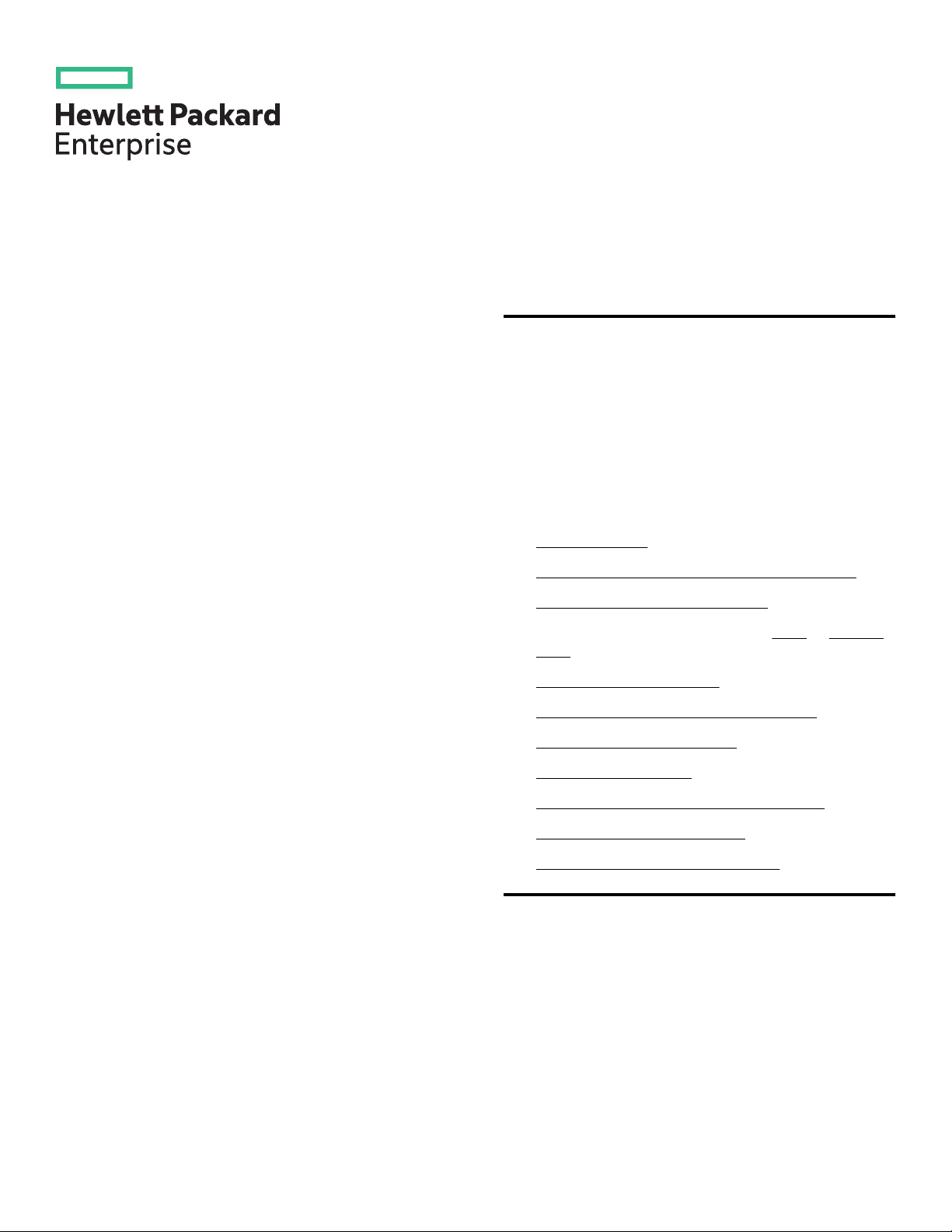
1. StoreOnce 5250 and 5650: Verify that the storage
enclosure has the required front and side clearance.
The clearance is required to allow hard drive
replacement.
• At least 1,000 mm to the front
• At least 300 mm to the right of the extended
drawer
2. Use rack stabilizers on racks that contain storage
enclosures.
IMPORTANT: See the rack documentation for
detailed instructions, including safety
information, about installing units within the
rack. Ensure that you have sufficient personnel
or lifting equipment to install the storage
enclosure safely.
3. StoreOnce 5250 and 5650: You can leave the disks
in the base enclosure during installation, but do not
add expansion disks until the storage enclosure is
installed in the rack.
Expansion disks ordered with the system are factoryinstalled in the base enclosure.
CAUTION: If the system was delivered with
further expansion disks loaded and configured,
assess the total weight. If you remove the disks
before installing to reduce weight, ensure that
they can be returned to their original
configuration. Use the supplied labels to record
the drawer and slot location of each disk.
Installing the server node and storage
enclosures in the rack - 5200
CAUTION: Use extreme caution when installing
and pulling units from the rack. Units can slip and
fall, damaging the HPE StoreOnce System or
causing personal injury. Hewlett Packard
Enterprise is not responsible for any damage or
injury caused by mishandling the HPE StoreOnce
System.
Page 2
Procedure
1. Install the server rails, as illustrated on the
installation instructions that ship with the rail kit.
NOTE: To leave room for future storage expansion,
install the base storage enclosure under the server
node. The system has a maximum of three
enclosures above the server node and three
enclosures under it.
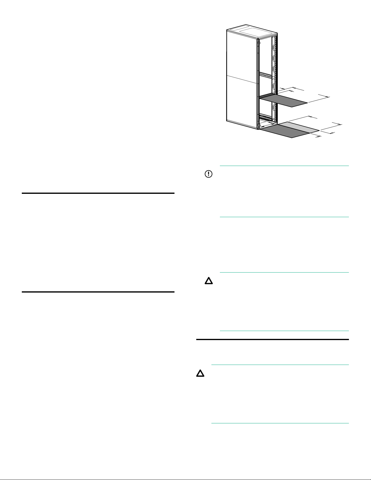
2. Adjust the back bracket on the standard rail kit to
accommodate the storage enclosure.
Attach rear hold down brackets by sliding the tab
with the arrow pointed forward (1) into the
corresponding slot on each side of the rear of the
chassis. Use the black headed thumb screw to
secure tightly to the rail in the second hole from the
rear (2).
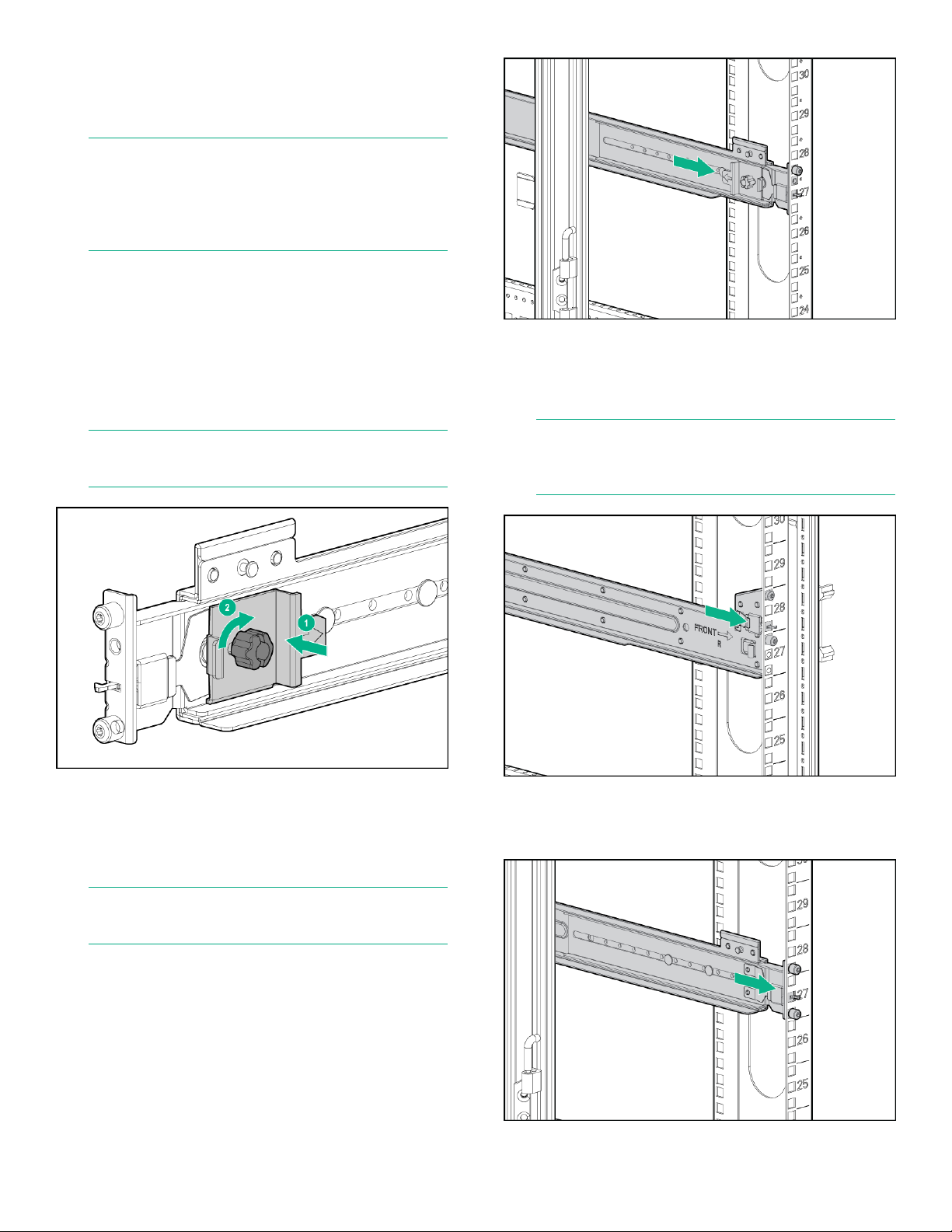
6. To engage the front, pull the rail towards the front of
the rack to engage the spring hook with the RETMA
column in the same manner as the rear spring
hook.
NOTE: It is easier to make this adjustment prior to
mounting the rails.
3. Position left and right rack rails at the desired 'U'
position in the rack, adjusting the rails to fit the rack,
as needed. Front and Rear bottom edge of rails
must align with the bottom of EIA boundary in the
lowermost 'U'
NOTE: Make sure that the respective guide pins for
the square or round hole rack align properly into
RETMA column hole spacing.
7. Secure the rear of the rack rail to the RETMA
column with either the provided round- or squarehole shoulder screws.
NOTE: Rails are marked L and R, with an arrow
indicating the direction the rail is installed.
4. Use guide pins to align the shelf mount kit to the
RETMA column holes.
5. To engage the rear, push the rail toward the back of
the rack until the spring hook snaps into place.
Page 3
 Loading...