

HP StoreOnce 3100, StoreOnce 3500, StoreOnce 5100, StoreOnce 5500 System Installation And Configuration Manual

StoreOnce 3100, 3500, 5100 and 5500 System Installation and Configuration Guide
Abstract
This guide is for StoreOnce System Administrators. It assumes that the user has followed the instructions on the appropriate
Start Here poster to create a basic network connection to the StoreOnce System.
Part Number: BB917-90903
Published: March 2016
Edition: 2

© Copyright 2015, 2016 Hewlett Packard Enterprise Development LP
The information contained herein is subject to change without notice. The only warranties for Hewlett Packard Enterprise products and services
are set forth in the express warranty statements accompanying such products and services. Nothing herein should be construed as constituting
an additional warranty. Hewlett Packard Enterprise shall not be liable for technical or editorial errors or omissions contained herein.
Confidential computer software. Valid license from Hewlett Packard Enterprise required for possession, use, or copying. Consistent with FAR
12.211 and 12.212, Commercial Computer Software, Computer Software Documentation, and Technical Data for Commercial Items are licensed
to the U.S. Government under vendor's standard commercial license.
Links to third-party websites take you outside the Hewlett Packard Enterprise website. Hewlett Packard Enterprise has no control over and is not
responsible for information outside the Hewlett Packard Enterprise website.
Acknowledgments
Intel®, Itanium®, Pentium®, Intel Inside®, and the Intel Inside logo are trademarks of Intel Corporation in the United States and other countries.
Microsoft® and Windows® are either registered trademarks or trademarks of Microsoft Corporation in the United States and/or other countries.
Adobe® and Acrobat® are trademarks of Adobe Systems Incorporated.
Java® and Oracle® are registered trademarks of Oracle and/or its affiliates.
UNIX® is a registered trademark of The Open Group.
Warranty
WARRANTY STATEMENT: To obtain a copy of the warranty for this product, see the warranty information website:
http://www.hpe.com/support/Storage-Warranties
Revision History
December 2015Revision 1
First edition with the HPE StoreOnce 3100, 3520 and 3540, and 5100 System product launch.
March 2016Revision 2
Second edition updated for the StoreOnce 5500 System product launch.

Contents
1 Preparing for Basic Configuration ......................................................................6
Structure of the guide...........................................................................................................................6
Overview of configuration tasks............................................................................................................6
StoreOnce Systems .............................................................................................................................7
StoreOnce 5500 System.................................................................................................................7
StoreOnce 3100 System.................................................................................................................7
StoreOnce 3500 Series...................................................................................................................7
StoreOnce 5100 System.................................................................................................................8
Hardware-related considerations..........................................................................................................8
Other sources of information................................................................................................................8
2 SAS cabling for StoreOnce 5500 Systems........................................................10
Basic installation.................................................................................................................................10
Expansion guidelines..........................................................................................................................11
SAS cable lengths..............................................................................................................................12
Expansion installation scenarios.........................................................................................................13
Two enclosures either side of the head server..............................................................................13
Up to four enclosures below the head server................................................................................13
3 Powering up and setting up iLO4......................................................................16
Powering up the StoreOnce 5500 System..........................................................................................16
Powering up StoreOnce 3100, 3500 and 5100 Systems....................................................................17
iLO functionality..................................................................................................................................18
iLO network name and iLO password...........................................................................................18
To configure iLO4, all systems............................................................................................................18
To set up a basic network configuration..............................................................................................20
4 Logging in to the StoreOnce System and checking status................................21
Supported web browsers....................................................................................................................21
Login to the StoreOnce System and check status..............................................................................21
StoreOnce CLI....................................................................................................................................21
5 Configuring licenses..........................................................................................23
Capacity expansion, StoreOnce 5500................................................................................................23
Pre-installed Capacity licenses.....................................................................................................23
Capacity expansion, StoreOnce 3100 System, StoreOnce 3500 Series and StoreOnce 5100
System................................................................................................................................................23
Security...............................................................................................................................................24
Target devices and stores...................................................................................................................24
StoreOnce Optional Hardware............................................................................................................24
Checking for installed licenses...........................................................................................................24
Applying a demo license.....................................................................................................................25
Applying a full license.........................................................................................................................25
To redeem a license......................................................................................................................25
To apply a full license....................................................................................................................26
6 Setting time zone and configuring NTP server..................................................27
Using the StoreOnce GUI to set the time zone ..................................................................................27
Using the StoreOnce GUI to configure NTP server............................................................................27
7 Creating user accounts and changing default passwords.................................29
Introduction.........................................................................................................................................29
To add a local user..............................................................................................................................29
To change passwords for local users..................................................................................................30
Contents 3

8 Setting up email alerts.......................................................................................31
To configure email settings.................................................................................................................31
To test email........................................................................................................................................31
Email Events notification.....................................................................................................................32
To manage email notifications.......................................................................................................32
9 Setting up SNMP (Simple Network Management Protocol) .............................33
Management Information Bases (MIBs).............................................................................................33
Configuring SNMP on the StoreOnce Management Console............................................................33
StoreOnce CLI...............................................................................................................................33
StoreOnce GUI .............................................................................................................................34
Modify the SNMP Agent Setup................................................................................................34
10 Generating the SSL certificate.........................................................................37
SSL certificates...................................................................................................................................37
To generate a self-signed certificate...................................................................................................37
11 Expanding storage capacity, if supported........................................................38
StoreOnce 3500 Series......................................................................................................................38
To view license details...................................................................................................................38
To view storage status...................................................................................................................38
StoreOnce 5100 System and StoreOnce 5500 System.....................................................................39
12 Checking for the latest software......................................................................40
Suppressing remote events................................................................................................................40
To check software version..................................................................................................................40
To view and upgrade firmware............................................................................................................40
13 Configuring Remote Support via STaTS.........................................................42
General procedure for setting up Remote Support via STaTS on the StoreOnce Management
GUI.....................................................................................................................................................42
More about warranty details...............................................................................................................43
14 Complete network configuration......................................................................44
To add a custom network configuration..............................................................................................44
15 Additional configuration tasks..........................................................................50
Saving the configuration and keystore ...............................................................................................50
Saving the configuration................................................................................................................50
Saving the encryption keystore.....................................................................................................50
Running a system confidence check .................................................................................................51
Configuring media servers to use StoreOnce Catalyst.......................................................................51
Driver installation on client server (optional, VTL only)......................................................................52
iSCSI Initiator (VTL only)....................................................................................................................52
16 Hardware overview reference section.............................................................53
StoreOnce 5500 System.....................................................................................................................53
StoreOnce 5500 System front and rear views, server...................................................................53
Front and rear views of the disk enclosure....................................................................................54
StoreOnce 3100 System.....................................................................................................................55
StoreOnce 3500 Series......................................................................................................................56
Storage expansion.........................................................................................................................56
Optional hardware.........................................................................................................................56
Front and rear views .....................................................................................................................56
StoreOnce 5100 System.....................................................................................................................57
Storage expansion.........................................................................................................................57
Optional hardware.........................................................................................................................57
Front and rear views......................................................................................................................58
StoreOnce 5100 System with Capacity Expansion............................................................................58
4 Contents

17 Optional PCIe cards........................................................................................60
PCIe slot allocation at delivery............................................................................................................60
Port numbering on PCI cards........................................................................................................61
Viewing hardware options...................................................................................................................62
Licensing hardware options...........................................................................................................62
18 More about network configuration...................................................................63
Understanding hardware configuration options..................................................................................63
Connecting to a 1 GbE network....................................................................................................63
Connecting to a 10 GbE network..................................................................................................63
Key definitions....................................................................................................................................64
Network bonding modes.....................................................................................................................65
VLAN guidelines.................................................................................................................................66
19 Configure Fibre Channel.................................................................................67
Fibre Channel hardware requirements...............................................................................................67
Supported Fibre Channel connections...............................................................................................67
Zoning............................................................................................................................................67
Configuring Fibre Channel..................................................................................................................68
For use with StoreOnce Catalyst stores........................................................................................68
For use with VTL libraries..............................................................................................................69
20 Support and other resources...........................................................................70
Accessing Hewlett Packard Enterprise Support.................................................................................70
Accessing updates..............................................................................................................................70
Related information.............................................................................................................................70
Websites.............................................................................................................................................71
Customer self repair...........................................................................................................................71
Documentation feedback....................................................................................................................71
A Warranty and regulatory information.................................................................72
Warranty information...........................................................................................................................72
Regulatory information........................................................................................................................72
Belarus Kazakhstan Russia marking.............................................................................................72
Turkey RoHS material content declaration....................................................................................73
Ukraine RoHS material content declaration..................................................................................73
Contents 5

1 Preparing for Basic Configuration
This guide assumes that the user has followed the instructions on the printed Start Here poster
to install the StoreOnce System in the Data Center and establish an initial 1 GbE network
connection for the StoreOnce Management Console.
IMPORTANT: All tasks described in this guide require an admin user logon.
Structure of the guide
The guide is divided into two sections. The first section is task based and describes how to log
in to the StoreOnce GUI to complete basic configuration tasks. The second section provides
reference information for the hardware and physical connection to Ethernet or Fibre Channel.
Overview of configuration tasks
Table 1 Configuration checklist
Refer toTask
1
connection to LAN port 1, which is valid for all products.
Make sure you understand what has been factory installed
and configured on your system and any further cabling
requirements. Available options for network and Fibre
Channel connectivity will depend upon the type of model.
4
Management application, such as Insight Remote Support,
configure iLO. (You can also configure iLO after
configuring the StoreOnce System.)
5
system, storage and optional hardware status.
Configure users.8
Hardware overview (page 53)The Start Here poster describes a basic installation with
Other sources of information (page 8)Make sure all reference material is to hand.2
SAS cabling for StoreOnce 5500 Systems (page 10)StoreOnce 5500 only: Review SAS cabling requirements.3
Powering up and setting up iLO (page 16)Boot up the system and, if you are using a Network
Logging in to the HPE StoreOnce System (page 21)Log on to the StoreOnce Management Console and check
Configuring licenses (page 23)Configure licenses.6
Setting time zone and configuring NTP (page 27)Configure time zone and NTP server.7
Creating user accounts and changing
passwords (page 29)
Setting up email alerts (page 31)Configure email.9
Setting up SNMP traps (page 33)Configure SNMP.10
18
on the system.
6 Preparing for Basic Configuration
Generating the SSL certificate (page 37)Apply the SSL certificate.11
Expanding storage (page 38)If necessary, expand storage.12
Checking software version (page 40)Check software version.13
Configuring Remote Support via STaTS (page 42)Configure Remote Support via STaTS.14
Completing network configuration (page 44)Configure the network.15
Configuring Fibre Channel (page 67)Configure Fibre Channel.16
Additional configuration tasks (page 50)Complete configuration.17
Running a system confidence check (page 51)Use the StoreOnce CLI to run a confidencecheck report
StoreOnce Systems
StoreOnce 5500 System
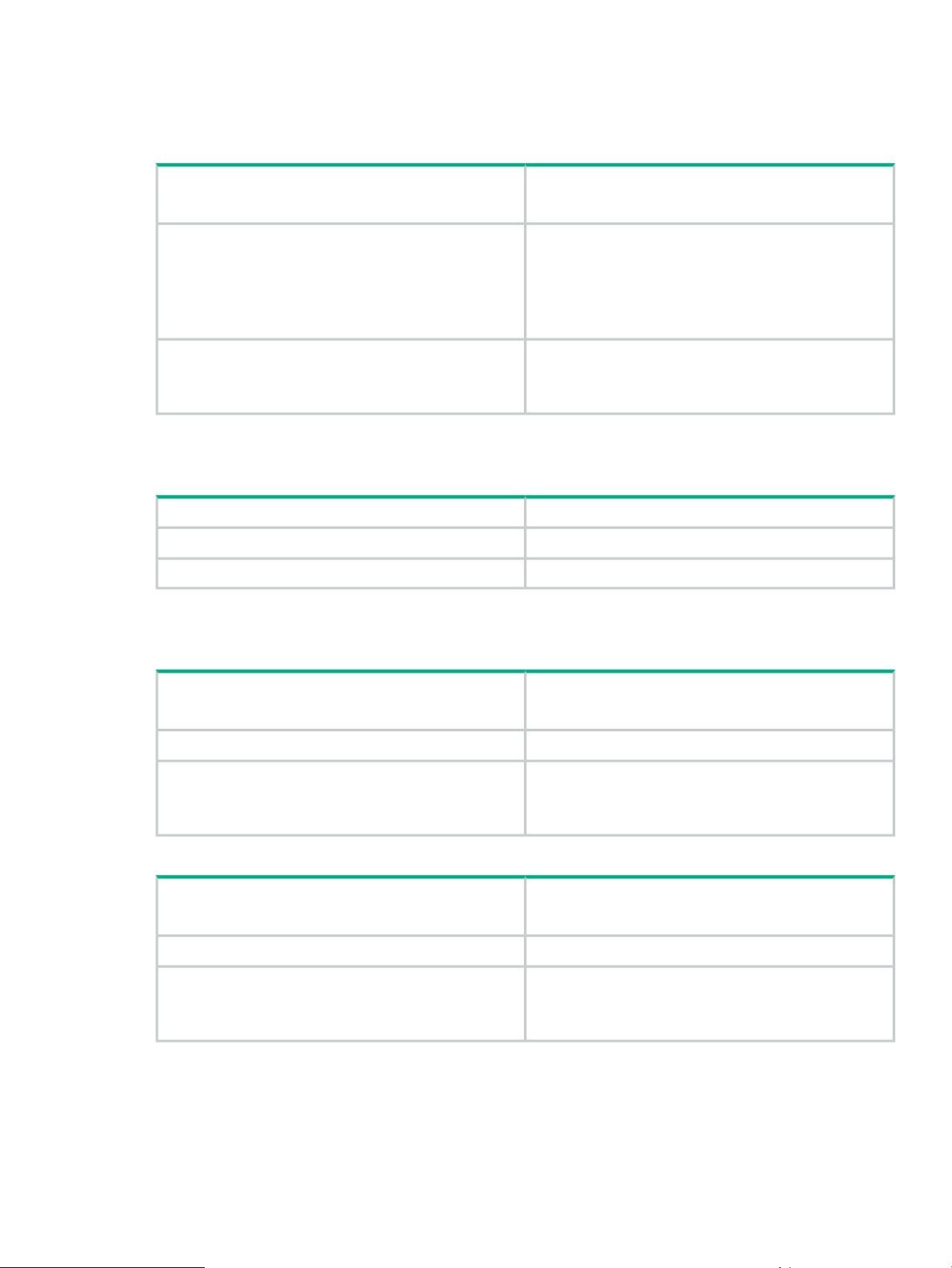
Table 2 StoreOnce 5500 System
60 TB (11 x 4 TB disks + 4 hot spare)Storage capacity
Maximum capacity = 1120 TB
There are two options:Storage Expansion Options
Add up to five 44 TB Capacity Upgrade disk packs
(containing eleven 4 TB disks) to each enclosure
Add up to three 60 TB Capacity Upgrade disk enclosures
(containing eleven 4 TB disks + 4 hot spare)
StoreOnce Optional Hardware
StoreOnce 3100 System
Table 3 StoreOnce 3100 System
StoreOnce 3500 Series
Table 4 StoreOnce 3520 System
StoreOnce Optional Hardware
Four PCIe slots are available for 10 GbE Network and FC
PCIe cards.
See Optional PCIe cards (page 60).
8 TB (4 x 2 TB disks)Storage capacity
NoneStorage Expansion Options
Not supportedStoreOnce Optional Hardware
12/24 TB (12 x 2 TB disks)Storage capacity
Base storage = 12 TB (50% capacity)
24 TB (100% capacity) requires additional licenseStorage Expansion Options
Four PCIe slots are available for 10 GbE Network and FC
PCIe cards.
See Optional PCIe cards (page 60).
Table 5 StoreOnce 3540 System
StoreOnce Optional Hardware
24/48 TB (12 x 4 TB disks)Storage capacity
Base storage = 24 TB (50% capacity)
48 TB (100% capacity) requires additional licenseStorage Expansion Options
Four PCIe slots are available for 10 GbE Network and FC
PCIe cards.
See Optional PCIe cards (page 60).
StoreOnce Systems 7

StoreOnce 5100 System
Table 6 StoreOnce 5100 System
48 TB (12 x 4 TB disks)Storage capacity
Maximum capacity = 288 TB
Storage Expansion Options
StoreOnce Optional Hardware
Hardware-related considerations
The StoreOnce System is supplied pre-configured according to the options specified at the time
of order. This means that any additional storage and/or Optional Hardware PCIe cards are already
installed. They should also be licensed and available for use.
Before you start the basic configuration tasks described in this guide verify the hardware installation
as follows:
• Verify what network connections are required for your backup environment. This determines
which network ports will be cabled in addition to the initial 1 GbE connection to LAN Port 1
described in the Start Here poster. See also More about network configuration (page 63).
• Verify that any Optional Hardware required for connection to the backup environment is
installed and licensed. See Hardware overview (page 53) for drawings that identify port and
slot locations for connecting to Ethernet networks and Fibre Channel SANs. See also Optional
PCIe cards (page 60).
• Verify what storage is available and that all storage is ready for use. The drawings in
Hardware overview (page 53) illustrate storage options for each model and any cabling
requirements. See also Expanding storage (page 38). For StoreOnce 5500 Systems refer
also to SAS cabling for StoreOnce 5500 Systems (page 10).
Up to five 48 TB Capacity Upgrade Kits may be connected
to base unit, each requires a separate license
Four PCIe slots are available for 10 GbE Network and FC
PCIe cards.
See Optional PCIe cards (page 60).
Other sources of information
The following documents are available from the HPE website at:
www.hpe.com/info/storeonce/docs
• StoreOnce Start Here posters: Quick Start installation posters are available for each model
and describe how to quickly install the StoreOnce System by connecting LAN Port 1 to a 1
GbE network.
• StoreOnce 5500 System Installation Planning and Preparation Guide: This guide provides
important information about planning for installation and future expansion. It also includes
detailed size, weight and power specifications.
• StoreOnce 5500 System Capacity Expansion Guide: This guide explains how to add disk
packs to a disk enclosure, how to connect additional storage enclosures to the StoreOnce
5500 System, and how to license and expand the storage.
• StoreOnce 5100 System Capacity Expansion Guide: This guide explains how to connect
additional storage enclosures to the StoreOnce 5100 System, and how to license and expand
the storage.
• StoreOnce System Optional Hardware Installation and Configuration Guide (not relevant for
3100): describes how to install and license StoreOnce Optional Hardware.
• StoreOnce System User Guide: This guide contains detailed information about the StoreOnce
Graphical User Interface (GUI) and troubleshooting information.
8 Preparing for Basic Configuration

• StoreOnce System CLI Reference Guide (for software version 3.14.0 and later): This is the
full reference guide for the StoreOnce Command Line Interface (CLI).
• StoreOnce System Linux and UNIX Configuration Guide: This guide explains how to configure
StoreOnce Systems with supported Linux and UNIX operating systems.
• OST plug-in documents: Various guides are available describing how to configure backup
applications for use with StoreOnce Catalyst. See Configuring media servers to use
StoreOnce Catalyst (page 51).
Other sources of information 9

2 SAS cabling for StoreOnce 5500 Systems
This chapter describes how to connect multiple disk enclosures to the StoreOnce 5500 System,
which has two RAID controller cards. It is included at the front of this guide for users who have
ordered a multi-enclosure configuration at installation because they need to understand how to
cable the disk enclosures to the correct RAID controller card.
IMPORTANT: It is important to plan for expansion when installing the basic system. The
StoreOnce 5500 System Installation Planning and Preparation Guide provides detailed information
about choosing a suitable location for the StoreOnce 5500 System, as well as size, weight and
power specifications for various expansion options. This document can be downloaded from:
www.hpe.com/info/storeonce/docs
All other StoreOnce Systems described in this guide have a single RAID controller card and
cabling diagrams for these systems are included in Hardware overview (page 53).
NOTE: Storage expansion steps with the StoreOnce 5500 System are also described in detail
in the StoreOnce 5500 System Capacity Upgrade Guide supplied as a printed document with
the product.
Basic installation
In this scenario, the disk enclosure bundled with the head server is installed above the server
and is connected to the RAID controller card in Slot 2. There is a 1U support shelf above the
head server to protect it from the weight of the disk enclosures. This is the installation that is
described in the printed StoreOnce 5500 Start Here poster, and is illustrated below.
NOTE: Within the StoreOnce software this enclosure is identified as Storage Cluster 1 and
volume and pool names have C2 as part of their naming convention, for example: Pool C2_P1
to Pool C2_P6.
10 SAS cabling for StoreOnce 5500 Systems
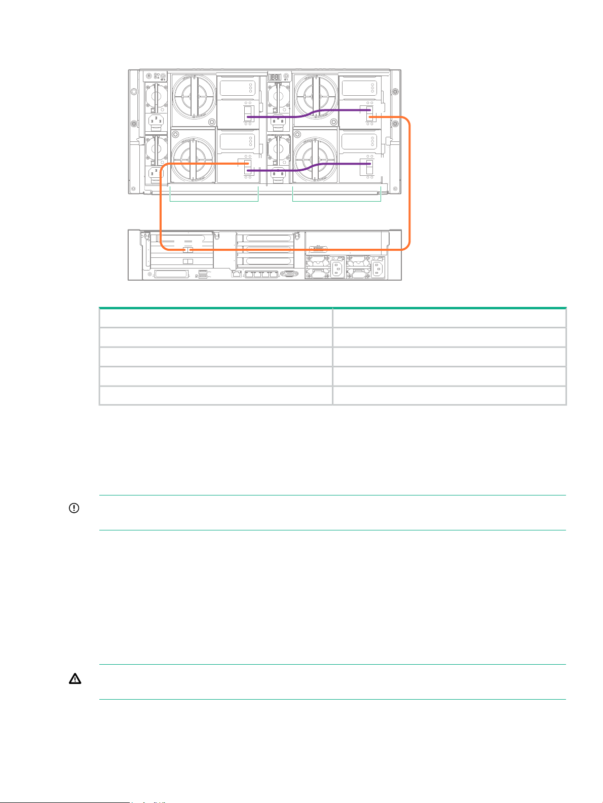
Figure 1 Cabling between head server, PCIe slot 2, and bundled enclosure
1
2
3
4
1
5
6
4
4
1
iLO
PS2
PS1
D1D2
IOM A
IOM B
IOM A
IOM B
P2
P1
P2
P1
P2
P1
P2
P1
P1P2
ToFrom
Expansion guidelines
Two installation scenarios are recommended:
• Two enclosures either side of the head server
• Four enclosures below the head server.
IMPORTANT: If you choose not to follow one of the recommended configurations, your system
may experience errors with the StoreOnce SAS check function that checks SAS cable integrity.
Refer to the StoreOnce 5500 System Capacity Upgrade Guide for detailed step-by-step cabling
instructions. Guidelines are as follows.
Enclosure connection sequence
• Connect the first enclosure to the RAID controller card in slot 2 of the head server.
• Connect the second enclosure to the RAID controller card in slot 3 of the head server.
• Daisy chain the third enclosure to the first enclosure.
Drawer 1, I/O module A, port 2Drawer 2, I/O module A, port 1
Drawer 1, I/O module B, port 2Drawer 2, I/O module B, port 1
Drawer 1, I/O module A, port 1RAID card in PCI slot 2, port 1
Drawer 2, I/O module B, port 2RAID card in PCI slot 2, port 2
• Daisy chain the fourth enclosure to the second enclosure.
WARNING! Never disconnect all SAS cabling at the same time while the system is powered
on. It is essential to maintain an active SAS connection throughout the expansion process.
Daisy chaining sequence
1. Connect the interlink cables between the two drawers in the new enclosure.
2. Connect the IOM A modules in the two enclosures.
Expansion guidelines 11
3. Make the connection from the P2 of the RAID controller to the newly added enclosure.
IMPORTANT: Do not disturb the SAS cabling between P1 of the RAID controller card and
the existing enclosure.
4. Connect the IOM B modules in the two enclosures.
SAS cable lengths
The StoreOnce implementation uses Managed Cables, making it easier to identify faults. The
StoreOnce software verifies that the correct length SAS cables are being used. Mini-SAS HD
connectors are used throughout.
SAS cables should ‘click’ and lock into position when correctly inserted. Three cable lengths are
available. The maximum supported cable length is 2.0 m.
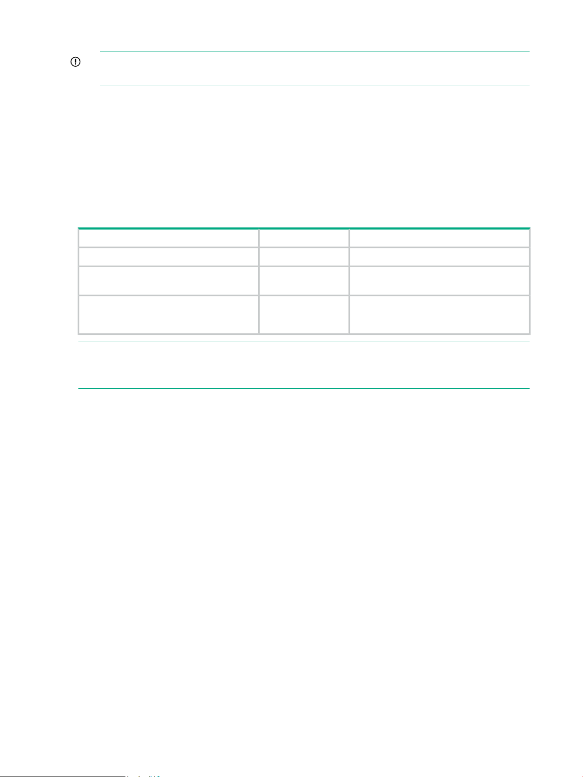
Table 7 Supported SAS cables
Location for usePart NumberDescription
Between drawers of a disk enclosure691970-0010.5 m Mini-HD SAS to Mini-HD SAS cable
691970-0021.0 m Mini-HD SAS to Mini-HD SAS cable
691970-0032.0 m Mini-HD SAS to Mini-HD SAS cable
Between disk enclosures or between the
server and the disk enclosure
Between the server and the disk enclosure if
the 1.0 m cable is not long enough. Do not
use to connect one disk enclosure to another.
NOTE: To facilitate future expansion, HPE recommends using 2.0 m SAS cables to connect
from the server to Drawer 2 of the disk enclosure. For this reason, the base system of one server
and one disk enclosure is supplied with two 0.5 m cables and two 2.0 m cables.
12 SAS cabling for StoreOnce 5500 Systems
Expansion installation scenarios
1
2
3
4
1
5
6
4
4
1
iLO
PS2
PS1
#1
#4
#2
#3
Two enclosures either side of the head server.
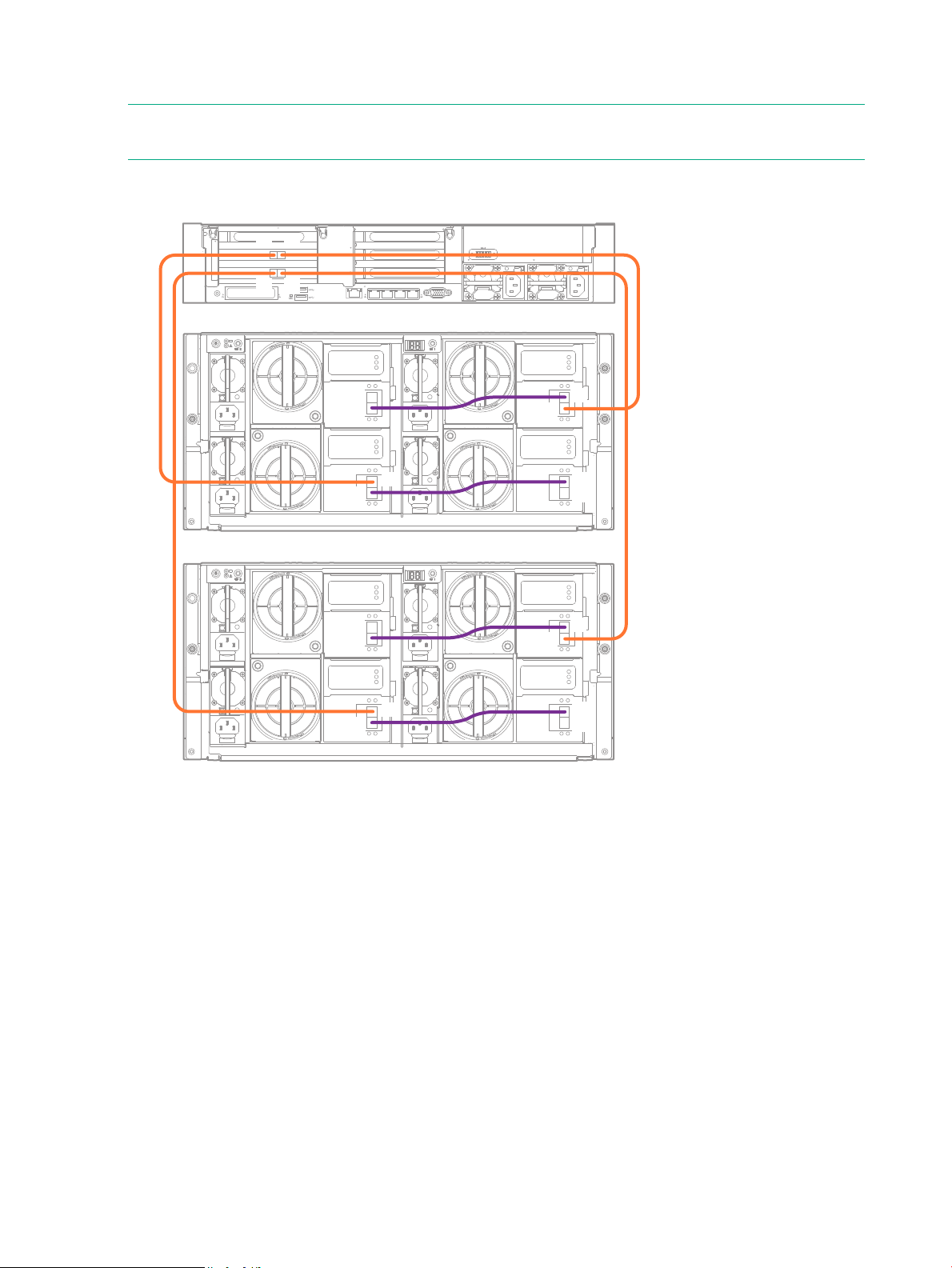
The following diagram illustrates the cabling for all four enclosures where two enclosures are
above and two enclosures are below the head server. This configuration provides equal weight
distribution in the rack. Refer to the StoreOnce 5500 System Capacity Upgrade Guide for detailed
step-by-step cabling instructions.
Figure 2 Cabling showing two enclosures installed either side of the head server
NOTE: Enclosure #1 and Enclosure #3 are in Storage Cluster 1, connected to the RAID
controller card in slot 2.
Enclosure #2 and Enclosure #4 are in Storage Cluster 2, connected to the RAID controller card
in slot 3.
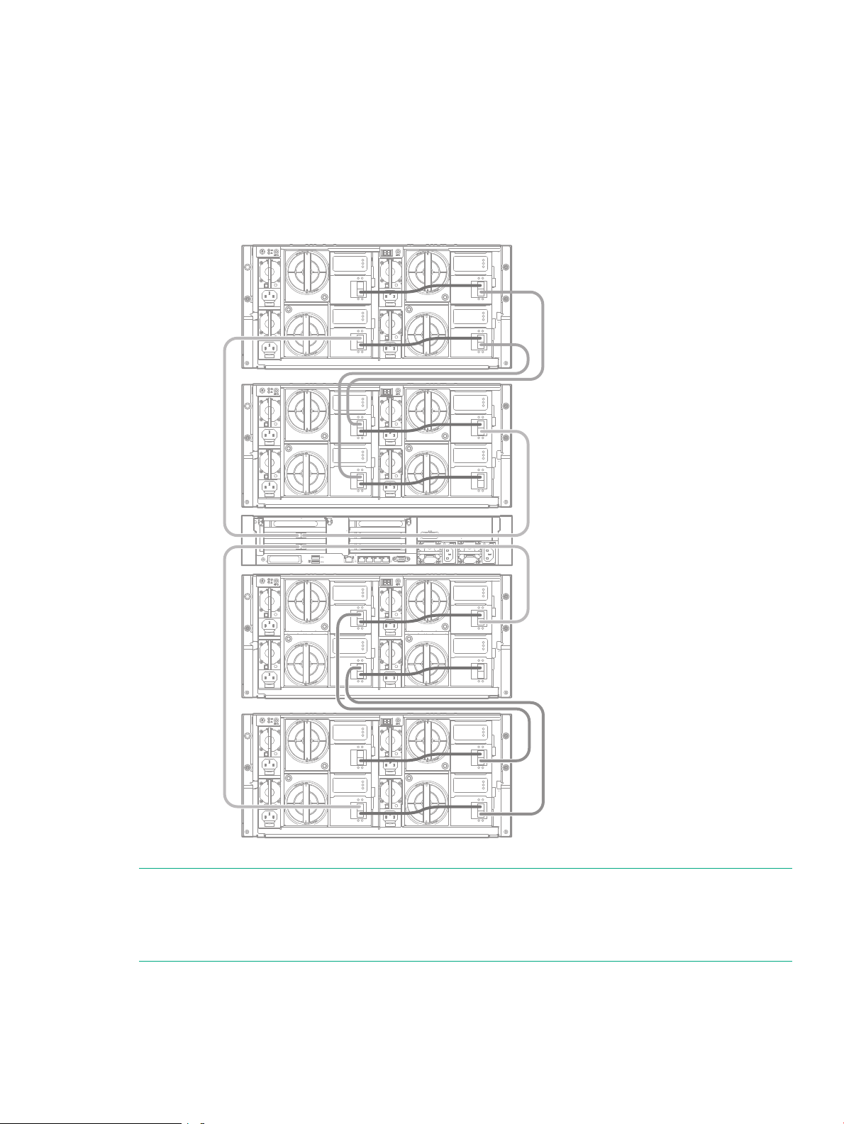
Up to four enclosures below the head server
The second recommended configuration has the head server at the top and all enclosures below
it. It requires one 1U support shelf, which should be installed below the last enclosure. This
Expansion installation scenarios 13
configuration provides easier access to the head server when cabling multiple enclosures. There
1
2
3
4
1
5
6
4
4
1
iLO
PS2
PS1
IOM A
IOM B
IOM A
IOM B
IOM A
IOM B
IOM A
IOM B
P2
P1
P2
P1
P2
P1
P2
P1
P2
P1
P2
P1
P2
P1
P2
P1
P1P2
P1P2
#2
#1
is a 1U support shelf underneath the lowest disk enclosure.
NOTE: If you choose not to follow one of the recommended configurations, your system may
experience errors with the StoreOnce SAS check function that checks SAS cable integrity.
Figure 3 Cabling showing two enclosures installed below the head server
14 SAS cabling for StoreOnce 5500 Systems

Figure 4 Cabling showing four enclosures installed below the head server
1
2
3
4
1
5
6
4
4
1
iLO
PS2
PS1
IOM A
IOM B
IOM A
IOM B
IOM A
IOM B
IOM A
IOM B
P2
P1
P2
P1
P2
P1
P2
P1
P2
P1
P2
P1
P2
P1
P2
P1
IOM A
IOM B
IOM A
IOM B
IOM A
IOM B
IOM A
IOM B
P2
P1
P2
P1
P2
P1
P2
P1
P2
P1
P2
P1
P2
P1
P2
P1
P1P2
P1P2
#2
#3
#4
#1
NOTE: Enclosure #1 and Enclosure #3 are in Storage Cluster 1, connected to the RAID
controller card in slot 2.
Enclosure #2 and Enclosure #4 are in Storage Cluster 2, connected to the RAID controller card
in slot 3.
Expansion installation scenarios 15
3 Powering up and setting up iLO4
2
1
3
4
SID
1 2 3 4 5 6 7 8
If the StoreOnce system has not yet been powered on, as described in the appropriate Start
Here poster, or if you need to configure iLO 4 from a direct connection, perform the following
steps.
Powering up the StoreOnce 5500 System
1. Perform a final check to ensure all cables are connected correctly and securely:
Head server unit
• Two power cables to the head server
• Keyboard and monitor cables
• Network cable to LAN port 1
• Network cable to iLO port
• Optional hardware — see the StoreOnce Optional Hardware Installation and
Configuration Guide
Disk enclosure(s)
• Four power cables to the disk enclosure
• Two 2m SAS cables from the disk enclosure to the first RAID controller card (slot 2)
• Two 0.5m SAS cables between the drawers on the disk enclosure
NOTE: See Hardware overview (page 53) for cabling examples.
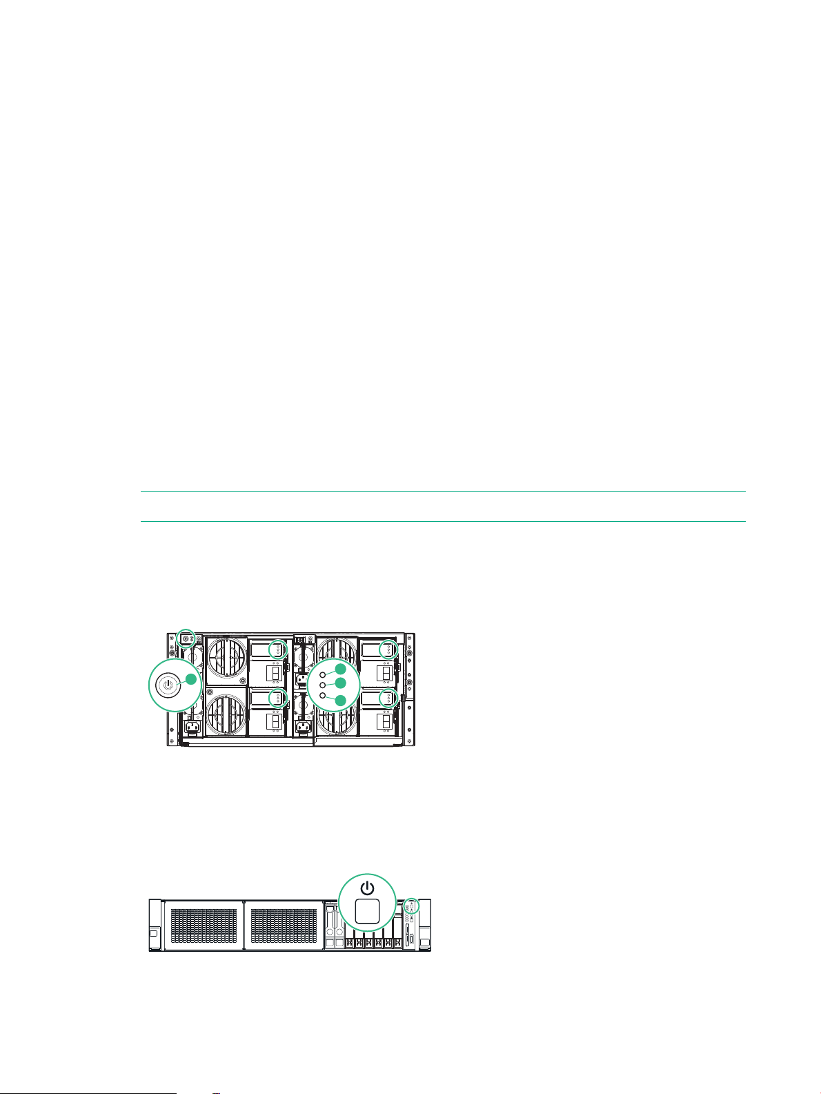
2. Power on all installed disk enclosures first. You may need to hold down the power on button
(1) on the rear of each unit for up to 30 seconds. Look at the LEDs on the I/O modules and
wait until the Green Status LED (3) remains on, and the Locate LED (2) and the Fault LED
(4) are both off.
3. Power on the HPE StoreOnce 5500 System (the power button is on the front of the unit).
The Power button LED flashes green during the power-on sequence, and the Power button,
System Health and NIC status LEDs all show steady green when the StoreOnce System is
powering up.
16 Powering up and setting up iLO4
Powering up StoreOnce 3100, 3500 and 5100 Systems
3 4
1 2 3 4
1. Perform a final check to ensure all cables are connected correctly and securely:
• Power cable(s)
• Keyboard and monitor cables
• Network cable to LAN port 1
• Network cable to iLO port
• Optional hardware, StoreOnce 3500 Series and StoreOnce 5100 System
• Capacity Upgrade Kits, StoreOnce 5100 System only
NOTE: See Hardware overview (page 53) for cabling examples.
2. Power on the StoreOnce System (the power button is on the front of the unit).
3. The Power button LED flashes green during the power-on sequence, and the Power button,
System Health and NIC status LEDs all show steady green when the StoreOnce System is
powering up.
NOTE: If you wish to configure iLO 4, press F9 in the ProLiant POST screen and proceed
as described in To configure iLO (page 18).
Figure 5 Powering up HPE StoreOnce 3100 System
NIC status LED2UID LED1
Power LED and on/off button4System health LED3
Powering up StoreOnce 3100, 3500 and 5100 Systems 17
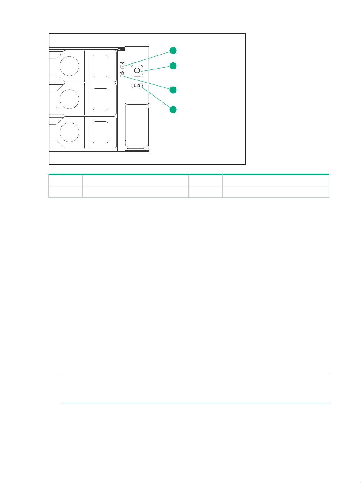
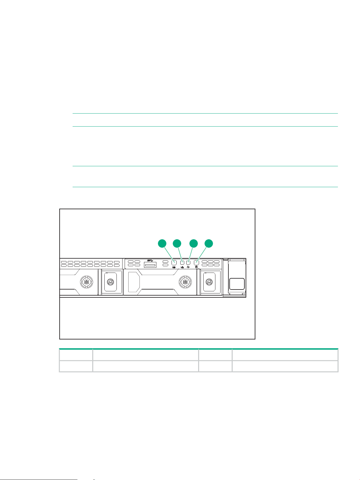
Figure 6 Powering up HPE StoreOnce 3500 Series and 5100 System
1
2
3
4
Power LED and on/off button2System health LED1
UID LED4NIC status LED3
iLO functionality
StoreOnce Systems are built on ProLiant server hardware and use the embedded Integrated
Lights-Out 4 (iLO 4) management technology. iLO enables secure remote monitoring and console
access via a web browser.
iLO is not required for daily management of the StoreOnce appliance but is useful in a lights-out
data center situation. iLO is also useful for diagnosing hardware failures that prevent access to
the appliance through the primary StoreOnce GUI or remote StoreOnce CLI interface.
iLO network name and iLO password
All StoreOnce Systems described in this guide are supplied with a label that includes the iLO
network name and iLO password. Ideally, the installer has made a note of this information, as
recommended in Step 3 of the printed Start Here guide. If not, it will be necessary to locate the
label on the top of the appliance in the data center.
It is good practice to either change the password after installation, or define an additional user
with privileges that can be used when accessing iLO from a web browser.
To configure iLO4, all systems
1. Boot up the StoreOnce System and watch the local console; the iLO4 IP addresses are
shown (IPv4 and IPv6).
NOTE: If the iLO port is plugged into a network that provides DHCP, the acquired addresses
will be shown here and you can connect to the network address in a web browser in order
to configure iLO.
2. If there are no DHCP–assigned IP addresses, you can manually configure iLO using the
local console. Press F9 in the ProLiant POST screen to access System Utilities. Select
System Configuration.
18 Powering up and setting up iLO4
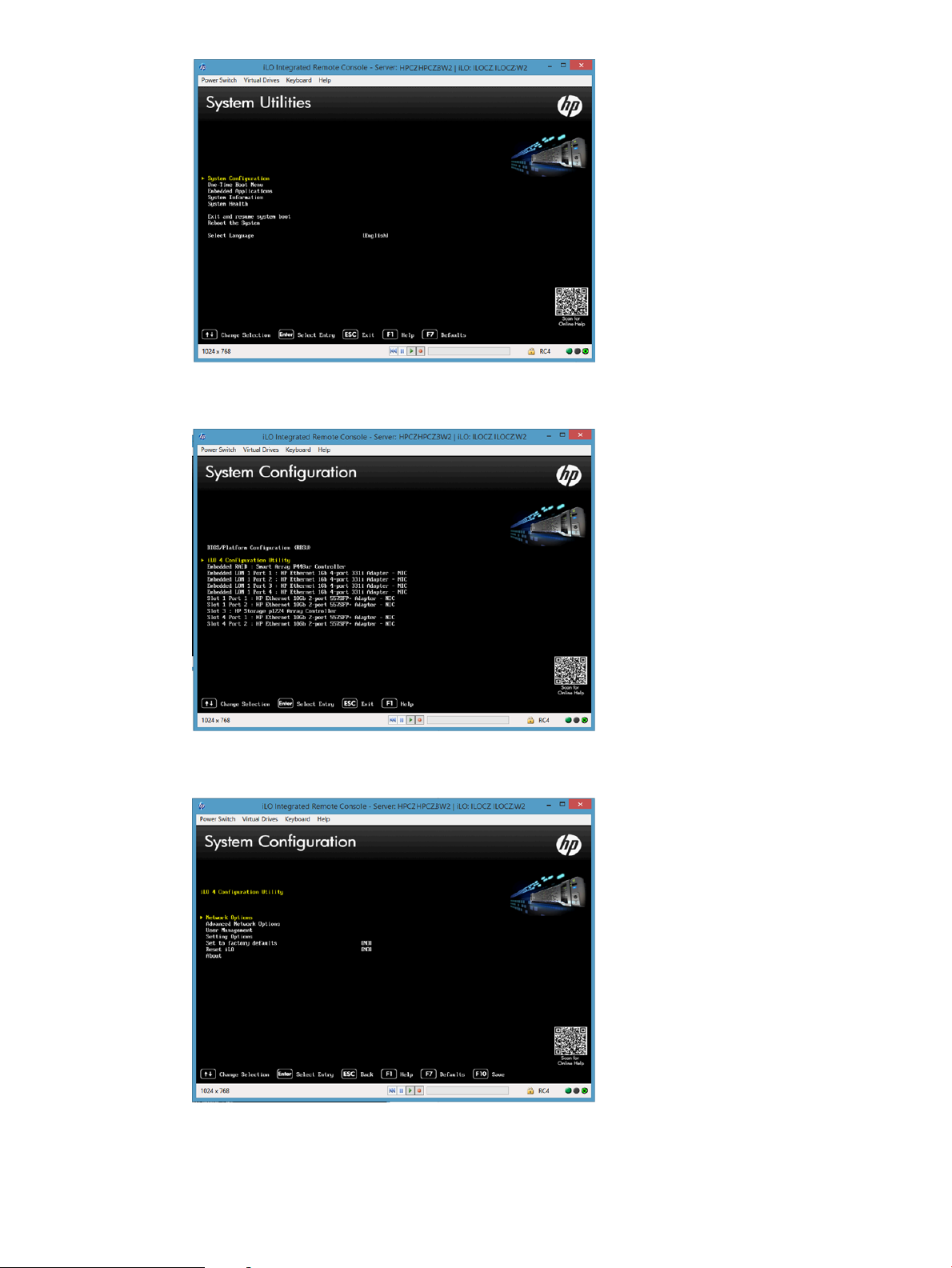
3. Select the iLO 4 Configuration Utility.
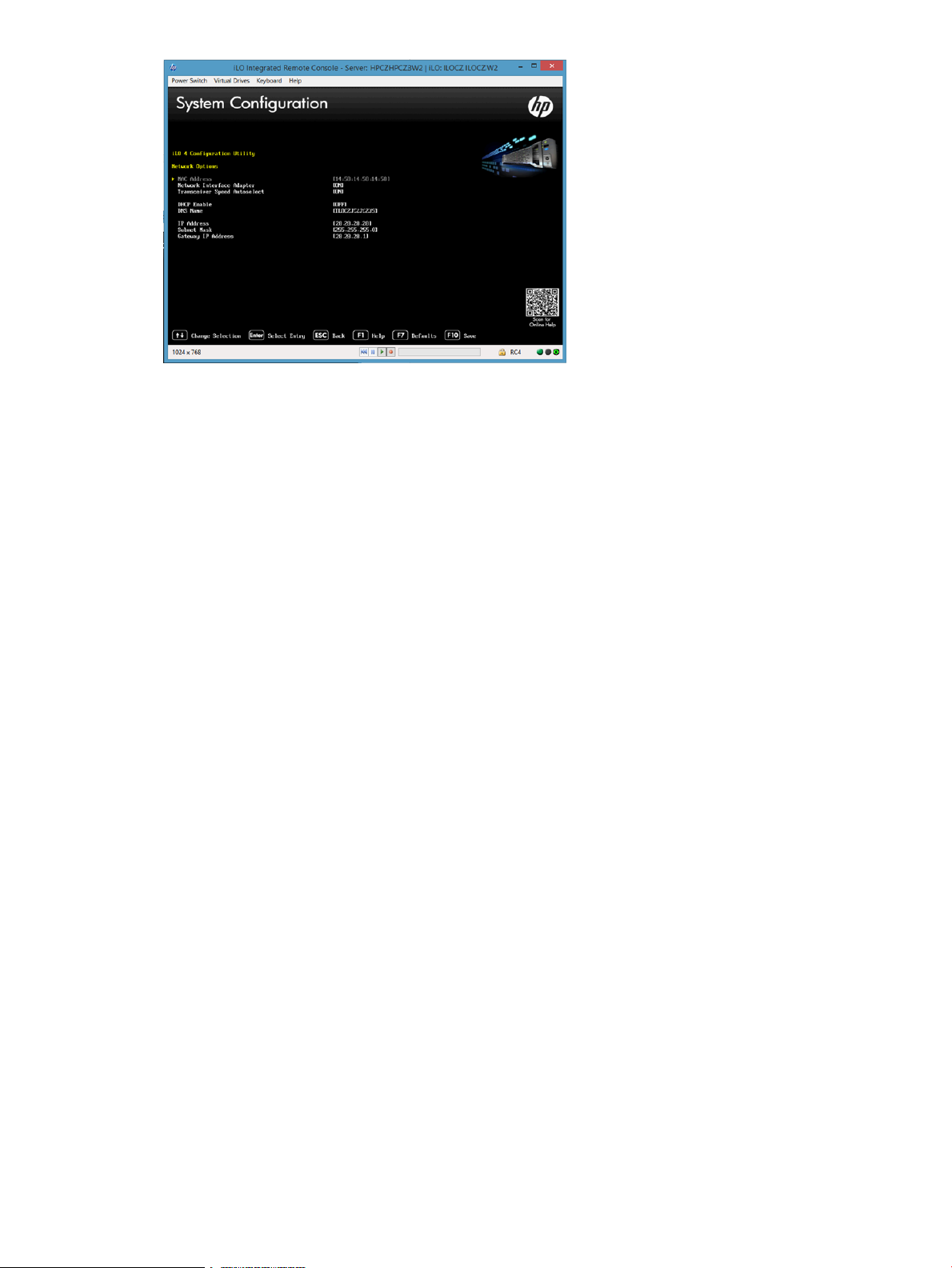
4. Select Network Options.
5. Configure your network settings and press F10 to save.
To configure iLO4, all systems 19
6. Then exit. The system will continue to boot normally into the StoreOnce OS.
To set up a basic network configuration
If you have not already done so, run the basic network script net set address as described
in the Start Here poster for your product, to configure a static address for LAN port 1 (eth0). Make
a note of the IP address details, which you will need to log into the StoreOnce System from a
web browser.
20 Powering up and setting up iLO4
4 Logging in to the StoreOnce System and checking status
The examples in this guide illustrate how to use the StoreOnce GUI to carry out configuration
tasks. However, all tasks may also be performed from the StoreOnce CLI, as described in the
StoreOnce System CLI Reference Guide.
Supported web browsers
The StoreOnce Management GUI is supported on the following web browsers:
• Internet Explorer 9, 10 and 11 (note that Internet Explorer 8 is not supported and some
StoreOnce features will not work)
• Mozilla FireFox v22 and above and Firefox ESR24 and above
IMPORTANT: The web browser used to communicate with the StoreOnce System requires
Active Scripting or JavaScript enabled. Without these scripts enabled, some browser buttons will
not display.
Login to the StoreOnce System and check status
To log on to the StoreOnce Management GUI, use any machine connected to the same network
as the appliance. The StoreOnce System uses a secure network connection.
1. Enter: https://<IP_address> .
You may also use the Fully Qualified Domain Name (FQDN).
NOTE: If you use http: in the URL, you are automatically forwarded to the https: secure
network connection.
2. The StoreOnce Management Console displays the Login prompt. Provide the default User
Name and Password (Admin, admin). You can also set the local language to display the
text within the StoreOnce GUI from the Login screen.
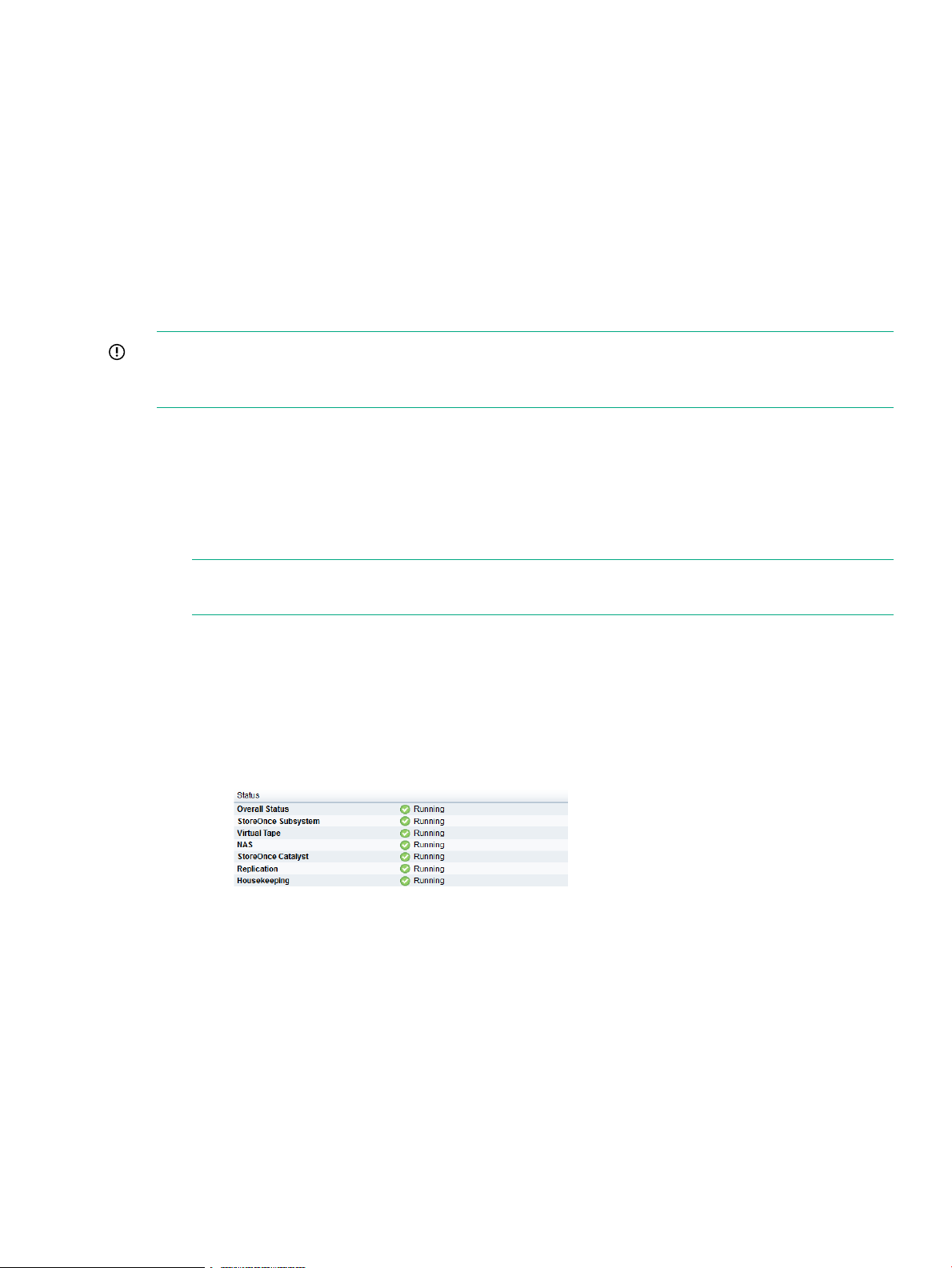
3. Look at the following pages to verify status information:
• StoreOnce to check the overall status and the status of all services. They should all
display with a green √ and Running.
• Device Configuration — License Management to see what licenses have been
applied. This page will also identify any Capacity Upgrade Kits and Optional Hardware
that has been installed and licensed. See Configuring licenses (page 23)
.
StoreOnce CLI
The tasks described in this guide can also be carried out using the StoreOnce CLI.
Supported web browsers 21

1. StoreOnce CLI commands require an SSH client application (freely available from the internet)
and must be run from a SSH terminal session on a machine that is on the same network as
the StoreOnce appliance:
ssh <username>@<ip_address>
NOTE: StoreOnce CLI commands can also be run from a local console (Keyboard and
Monitor) attached to the appliance, for example, if the network is not yet configured.
2. At the prompts provide a User Name and Password (Admin, admin).
3. See the StoreOnce System CLI Reference Guide for more information.
22 Logging in to the StoreOnce System and checking status
 Loading...