


OneCommand
Application
Version 6.0
User Manual
™
Manager
Emulex Connects™
P007450-01A Rev. A Servers, Storage and People

Copyright © 2003-2011 Emulex. All rights reserved worldwide. No part of this document may be reproduced by any
means or translated to any electronic medium without the prior written consent of Emulex.
Information furnished by Emulex is believed to be accurate and reliable. However, no responsibility is assumed by
Emulex for its use; or for any infringements of patents or other rights of third parties which may result from its use.
No license is granted by implication or otherwise under any paten t, copyrigh t or rela ted ri ghts of Emulex .
Emulex, the Emulex logo, AutoPilot Installer, AutoPilot Manager, BlockGuard, Connectivity Continuum,
Convergenomics, Emulex Connect, Emulex Secure, EZPilot, FibreSpy, HBAnyware, InSpeed, LightPulse,
MultiPulse, OneCommand, OneConnect, One Network. One Company., SBOD, SLI, and VEngine are trademarks of
Emulex. All other brand or product names referenced herein are trademarks or registered trademarks of their
respective companies or organizations.
Emulex provides this manual "as is" without any warranty of any kind, either expressed or implied, including but not
limited to the implied warranties of merchantability or fitness for a particular purpose. Emulex may make
improvements and changes to the product described in this manual at any time and without any notice. Em ulex
assumes no responsibility for its use, nor for any infringements of patents or other rights of third parties that may
result. Periodic changes are made to information contained herein; although these changes will be incorporated into
new editions of this manual, Emulex disclaims any undertaking to give notice of such changes.
Emulex, 3333 Susan Street
Costa Mesa, CA 92626
OpenSolaris DHCHAP Notice.
Contains portions of Covered Software subject to the Common Development and Distribution License (CDDL)
Version 1.0. Such portions of Covered Software in Source Code form may be obtained from the web site
www.opensolaris.org, or by contacting online support from the web site www.emulex.com.
Derived from the RSA Data Security, Inc. MD5 Message-Digest Algorithm.
Copyright (C) 1991-2, RSA Data Security, Inc. Created 1991. All rights reserved.
The OneCommand Manager User Manual Page ii

Introduction.............................................................................................................. 1
New Features in this Release............................................................................ 1
Compatibility......................................................................................................1
Supported Features by Operating System.........................................................2
Known Issues.................................................................................................... 3
Installing and Uninstalling OneCommand Manager
Application Components.......................................................................................... 4
Installing the OneCommand Manager Application.............................................4
In Windows ................................................................................................. 4
Attended Installation in Windows ..........................................................4
Unattended Installation in Windows......................................................7
In Solaris..................................................................................................... 8
In Linux .......................................................................................................9
In VMware ESX Server .............................................................................10
Installing the OneCommand Manager Application Web Launch Interface ....... 11
Prerequisites............................................................................................. 11
Procedures................................................................................................ 12
Installing the OneCommand Manager Application Command Line Interface... 13
In Windows ............................................................................................... 14
Unattended Installation in Windows.................................................... 15
In VMware ESX Server .............................................................................15
Prerequisites ....................................................................................... 15
Procedures ......................................................................................... 15
In a VMware ESX Server with an Existing HBAnyware CLI Kit Installed... 16
Uninstalling Older HBAnyware Kits on VMware..................................16
In Linux .....................................................................................................16
Prerequisites ....................................................................................... 16
Procedures ......................................................................................... 17
In a Linux System with an Existing HBAnyware CLI Kit Installed .......17
Uninstalling Older HBAnyware Kits on Linux.......................................18
In Solaris................................................................................................... 19
Prerequisites ....................................................................................... 19
Procedures ......................................................................................... 19
Upgrading from the OneCommand Manager Application CLI to the
Full-Featured OneCommand Manager Application Enterprise Kit ................... 19
In Windows ............................................................................................... 19
In Linux .....................................................................................................20
In Solaris................................................................................................... 20
In VMware ESX Server .............................................................................20
Uninstalling the OneCommand Manager Application ................................ 20
In Windows ............................................................................................... 20
In Solaris................................................................................................... 21
In Linux ....................................................................................................21
In VMware.................................................................................................21
Uninstalling the OneCommand Manager Application Web Launch
Interface Only.................................................................................................. 21
Starting and Stopping the OneCommand Manager
Application.............................................................................................................22
Starting the OneCommand Manager Application Web Launch Interface......... 23
Managing Files when Running the OneCommand Manager
Application Web Launch Interface............................................................. 23
The OneCommand Manager User Manual Page iii

Using the OneCommand Manager Application...................................................... 24
The OneCommand Manager Application Window Element Defin itions ........... 24
The Menu Bar ...........................................................................................25
The Toolbar............................................................................................... 25
The Toolbar Buttons.................................................................................. 25
The Discovery-Tree................................................................................... 26
Discovery-Tree Icons..........................................................................27
Expanding or Collapsing the Discovery-Tree View..............................28
The Property Tabs..................................................................................... 28
The Status Bar..........................................................................................28
Changing Management and Read-Only Mode................................................. 28
The Management Host..............................................................................29
In Windows......................................................................................... 29
In Solaris............................................................................................. 30
In Linux...............................................................................................30
Configuring Discovery ...........................................................................................30
Automatic FC Discovery.................................................................................. 30
Remote SAN Management Using TCP/IP Access Protocol............................. 31
The Hosts File................................................................................................. 32
Manually Editing the Hosts File.................................................................32
Copying the File........................................................................................33
Adding a Single Host....................................................................................... 33
Adding a Range of Hosts................................................................................. 34
Removing Hosts..............................................................................................36
Configuring Discovery and CIM Credentials....................................................36
Configuring iSCSI Target Discovery ................................................................ 39
Adding Target Portals................................................................................40
Removing a Target Portal.......................................................................... 40
Logging into Targets .................................................................................. 40
Manually Adding an iSCSI Target.............................................................. 42
Removing Targets..................................................................................... 42
Viewing Target Sessions...........................................................................42
Logging out of Target Sessions................................................................. 42
Configuring iSNS for iSCSI Target Discovery.................................................. 45
Viewing Discovery Information...............................................................................47
Viewing Host Grouping Information................................................................. 48
Viewing Host Information.................................................................................48
Grouping Hosts ............................................................................................... 50
Managing Host Groups ............................................................................. 51
Creating a Host Group........................................................................52
Deleting a Host Group ........................................................................ 52
Adding a Host to a Host Group........................................................... 53
Removing a Host from a Host Group.................................................. 53
Restoring a Host Group...................................................................... 53
Restoring all Host Groups................................................................... 53
Exporting Host Grouping Configurations.............................................53
Searching for Hosts.........................................................................................54
Viewing Adapter Information ........................................................................... 54
Viewing FC Adapter Information ............................................................... 54
Viewing OneConnect Adapter Information ................................................ 55
Viewing OneConnect Multi-ASIC Adapter Information ..............................58
Viewing ASIC Information................................................................................58
The OneCommand Manager User Manual Page iv

Viewing Port Information .................................................................................60
Viewing FC Port Information ..................................................................... 60
Viewing FCoE Port Information.................................................................62
Viewing iSCSI Port Information.................................................................64
Viewing NIC Port Information....................................................................66
Viewing Physical Port Information (OneConnect Adapters Only) .................... 68
Viewing Port Statistics..................................................................................... 69
Viewing FC/FCoE Port Statistics............................................................... 69
Viewing iSCSI Statistics ............................................................................72
Viewing FC Virtual Port Information (FC and FCoE Adapters Only)............... 74
Viewing FC Fabric Information (FC and FCoE Adapters Only)........................ 74
Viewing Transceiver Information .....................................................................75
Viewing FC Transceiver Information..........................................................75
Viewing OneConnect Adapter Transceiver Information.............................77
Viewing PHY Data (OneConnect OCe11100 series Adapters Only)................ 78
Viewing Vital Product Data (VPD)....................................................................80
Viewing VPD (FC adapters)...................................................................... 80
Viewing VPD (OneConnect adapters).......................................................80
Viewing Maintenance/Firmware Information.................................................... 81
Viewing FC Maintenance Information........................................................ 81
Viewing FCoE Maintenance Information ...................................................83
Viewing OneConnect Adapter Firmware Information ................................. 85
Viewing Target Information.............................................................................. 86
Viewing FC/FCoE Target Information........................................................ 87
Viewing iSCSI Target Information.............................................................. 87
Viewing LUN Information.................................................................................89
Viewing FC/FCoE LUN Information...........................................................89
Viewing iSCSI LUN Information ................................................................91
Viewing FC/FCoE Target Mapping (Windows and Solaris).............................. 92
Viewing Target Mapping (Linux and VMware ESX) .........................................93
Viewing iSCSI and NIC PCI Registers............................................................. 94
Viewing iSCSI PCI Registers .................................................................... 94
Viewing NIC PCI Registers ....................................................................... 95
Managing Adapters ...............................................................................................96
Managing Devices using CIM.................................................................... 96
Showing and Installing Licenses for OneConnect Adapters ............................ 96
Showing Licenses..................................................................................... 97
Installing Licenses..................................................................................... 98
Changing Personalities on OneConnect Adapters........................................... 99
Configuring the FC/FCoE Adapter Driver ...................................................... 100
The Host Driver Parameters Tab............................................................. 101
Setting Driver Parameters....................................................................... 103
Setting Driver Parameters for a Single Adapter ................................103
Restoring All Parameters to Their Earlier Values ..............................104
Resetting All Default Values.............................................................. 104
Setting an Adapter Parameter Value to the Host Adapter
Parameter Value............................................................................... 105
Saving Adapter Driver Parameters to a File...................................... 105
Setting Driver Parameters for All Adapters in a Host ........................ 105
Changing Non-dynamic Parameter Values (Linux 8.2)......................106
Changing Non-dynamic Parameter Values (VMware ESX)............... 107
Creating a Batch Mode Driver Parameters File....................................... 107
Assigning Batch Mode Parameters...................................................108
The OneCommand Manager User Manual Page v

Configuring DCB (Data Center Bridging) Parameters................................... 110
Configuring CEE/FCoE-Specific Parameters (LP21000 Series
Adapters Only)........................................................................................ 110
Configuring DCB Parameters for OneConnect Adapter Ports ..................111
Configuring DCB Parameters for iSCSI Adapter Ports............................ 116
Configuring DCB Parameters for NIC-Only Adapter Ports ......................120
Configuring FCoE Initialization Protocol (FIP) for FCoE Adapters.................124
Managing Ports ................................................................................................... 125
Changing Adapter Port Names (FC Ports Only)............................................ 125
Resetting Adapter Ports (FC/FCoE Ports Only)............................................. 126
Modifying TCP/IP iSCSI Port Configuration ................................................... 127
Advanced TCP/IP Configuration .............................................................128
Enabling and Disabling FC Ports................................................................... 129
Enabling and Disabling Physical Ports (OneConnect Adapters Only)............ 129
Setting Port Speed and DAC Cable Length (OneConnect OCe11102
Series Adapters Only) ...................................................................................129
Configuring iSCSI Port Initiator Login Options............................................... 131
Changing World Wide Name Configuration (FC/FCoE Ports Only) ............... 134
Creating and Deleting FC Virtual Ports (FC and FCoE Ports Only)............... 137
Creating Virtual Ports.............................................................................. 137
Deleting Virtual Ports .............................................................................. 139
Using FC-SP DHCHAP Authentication (Windows, Linux 8.2 and Solaris) ........... 141
Linux Considerations..................................................................................... 142
Enabling Authentication................................................................................. 142
The DHCHAP Tab .........................................................................................143
Changing Authentication Configuration...................................................144
Changing Your Password.................................................................. 145
Viewing the Error and Event Log ...................................................... 145
Updating Adapter Firmware................................................................................. 146
Updating Firmware for a Single Adapter........................................................ 146
Updating Firmware for Multiple Adapters ......................................................147
Updating CEE Firmware for a Single Adapter (LP21000 Series
Adapters Only) ..............................................................................................150
Updating CEE Firmware on Multiple Adapters (LP21000 Series
Adapters Only) ..............................................................................................152
Mapping and Masking (FC and FCoE Ports Only)............................................... 155
Automapping SCSI Devices (Windows)......................................................... 155
Mapping and Masking Defaults (Windows) ............................................. 156
Masking and Unmasking LUNs (Windows) ............................................. 156
Using Automapping and Persistent Binding (Windows)................................. 158
Changing Automapping Settings............................................................. 158
Adding a Persistent Binding.................................................................... 159
Binding a Target that Does Not Appear in the Persistent
Binding Table .......................................................................................... 160
Adding New Targets Using sd.conf (Solaris 8, 9 and 10).........................161
Configuring Boot from SAN ................................................................................. 161
Boot Types....................................................................................................161
Boot Device Parameters................................................................................162
Configuring Advanced Settings (Boot from SAN) ..........................................165
The OneCommand Manager User Manual Page vi

Exporting SAN Information ..................................................................................169
Diagnostics.......................................................................................................... 170
LightPulse FC HBA Diagnostics.................................................................... 170
Viewing Flash Contents, PCI Registers and Wakeup Information ........... 171
Viewing Flash Contents...........................................................................171
Viewing Overlay Details ..........................................................................172
Viewing the PCI Registers.......................................................................172
Running a Quick Test..............................................................................172
Running a Power On Self Test (POST) ...................................................173
Using Beaconing..................................................................................... 173
Creating Diagnostic Dumps..................................................................... 173
Running Advanced Diagnostic Tests.......................................................175
Running Loopback Tests......................................................................... 176
Loopback Test Combinations ..................................................................176
Running End-to-End (ECHO) Tests......................................................... 178
Saving the Log File ................................................................................. 179
OneConnect Diagnostics............................................................................... 180
OneConnect Loopback Test Combinations ............................................. 181
Using Beaconing..................................................................................... 183
Saving the Log File ................................................................................. 183
Creating Diagnostic Dumps..................................................................... 184
Using the OneCommand Manager Application Command Line
Interface .............................................................................................................. 187
Managing Devices Using CIM ....................................................................... 187
The CLI Client Command Reference...................................................................191
Using the CLI Client ...................................................................................... 191
Syntax Rules........................................................................................... 191
Syntax Rules for CIM........................................................................191
The Command Reference .............................................................................193
Commands Not Supported in Linux and Solaris ..................................... 193
Commands Not Supported in VMware ESX............................................ 193
Commands Supported in CIM Interface .................................................. 193
Commands Supported in CIM Provider 3.0....................................... 193
Commands Supported in CIM Provider 3.1....................................... 194
Commands Supported in CIM Provider 3.2....................................... 194
Commands Supported in CIM Provider 3.4.4.................................... 194
Commands Supported in CIM Provider 3.5....................................... 194
Commands Supported in Target-mode Ports .........................................195
Parameters Not Supported in the CIM Interface...................................... 195
Read-Only Mode.....................................................................................195
Help Command ............................................................................................. 196
Help ........................................................................................................ 196
Adapter License Management Commands ................................................... 196
InstallAdapterLicense..............................................................................196
ShowAdapterLicenseFeatures ................................................................197
ShowLicenseAdapterID........................................................................... 197
Attributes Commands.................................................................................... 198
HbaAttributes.......................................................................................... 198
PortAttributes.......................................................................................... 198
PortStatistics...........................................................................................199
ServerAttributes ......................................................................................199
The OneCommand Manager User Manual Page vii

SetPfcThrottle .........................................................................................199
SetPortEnabled....................................................................................... 200
SetPhyPortSpeed.................................................................................... 200
Authentication Commands ............................................................................ 201
AuthConfigList......................................................................................... 201
DeleteAuthConfig.................................................................................... 201
GetAuthConfig ........................................................................................202
GetAuthStatus......................................................................................... 202
InitiateAuth.............................................................................................. 202
SetAuthConfig......................................................................................... 202
SetPassword........................................................................................... 203
Boot Commands............................................................................................ 204
EnableBootCode.....................................................................................204
GetBootParams.......................................................................................204
SetBootParam......................................................................................... 206
CEE Commands............................................................................................ 206
CEEDownload ......................................................................................... 206
GetCEEParams....................................................................................... 207
SetCEEParam.........................................................................................207
Data Center Bridging Commands.................................................................. 208
GetDCBParams ...................................................................................... 208
GetPGInfo...............................................................................................208
SetCnaPGBW......................................................................................... 209
SetDCBParam.........................................................................................209
SetDCBPriority........................................................................................ 211
FCoE Adapter Specific Rules:........................................................... 211
iSCSI Adapter Specific Rules:........................................................... 211
NIC Adapter Specific Rules:.............................................................. 211
Diagnostic Commands .................................................................................. 212
EchoTest................................................................................................. 212
GetBeacon..............................................................................................212
GetXcvrData ........................................................................................... 213
LoadList ..................................................................................................213
LoopBackTest ......................................................................................... 214
LoopMap.................................................................................................214
PciData ...................................................................................................215
PostTest..................................................................................................216
SetBeacon .............................................................................................. 216
SetCableNVP.......................................................................................... 217
Wakeup...................................................................................................217
Driver Parameter Commands .......................................................................218
DriverConfig............................................................................................218
GetDriverParams .................................................................................... 218
GetDriverParamsGlobal.......................................................................... 219
SaveConfig ............................................................................................219
SetDriverParam ......................................................................................220
SetDriverParamDefaults..........................................................................220
Dump Commands..........................................................................................221
DeleteDumpFiles.....................................................................................221
Dump ......................................................................................................221
GetDumpDirectory .................................................................................. 222
SetDumpDirectory................................................................................... 222
GetDumpFile........................................................................................... 223
GetDumpFileNames................................................................................ 224
The OneCommand Manager User Manual Page viii

GetRetentionCount ................................................................................. 224
SetRetentionCount .................................................................................. 225
FCoE Commands.......................................................................................... 225
GetFCFInfo............................................................................................. 225
GetFIPParams ........................................................................................ 226
SetFIPParam ..........................................................................................226
iSCSI Commands.......................................................................................... 227
AddARPTableEntry ................................................................................. 227
AddRouteTableEntry............................................................................... 228
AddTarget................................................................................................228
AddTargetPortal ......................................................................................229
CleariSNSServer ..................................................................................... 231
DelARPTableEntry .................................................................................. 231
DelRouteTableEntry................................................................................ 231
DiscoveriSNSServer ............................................................................... 232
GetInitiatorProperties.............................................................................. 232
GetiSCSILuns .........................................................................................232
GetiSCSIPortStats................................................................................... 233
GetSessionInfo ....................................................................................... 233
iSCSIPing................................................................................................233
ListSessions............................................................................................234
RemoveTarget......................................................................................... 234
RemoveTargetPortal ............................................................................... 234
SetInitiatorProperties ..............................................................................235
SetNetworkConfiguration ........................................................................ 236
SetTargetLoginProperties........................................................................237
SetTargetProperties ................................................................................ 238
SetTPLoginProperties.............................................................................238
ShowARPTable....................................................................................... 239
ShowiSNSServer .................................................................................... 240
ShowRouteTable..................................................................................... 240
ShowTarget.............................................................................................240
ShowTargetPortal .................................................................................... 241
TargetLogin............................................................................................. 241
TargetLogout...........................................................................................242
UpdateiSNSServer.................................................................................. 243
LUN Masking Commands ............................................................................. 243
GetLunList...............................................................................................243
GetLunUnMaskByHBA............................................................................ 244
GetLunUnMaskByTarget......................................................................... 244
RescanLuns............................................................................................ 244
SetLunMask............................................................................................245
Miscellaneous Commands ............................................................................245
AddHost.................................................................................................. 245
CnaClearEventLog.................................................................................. 246
CnaGetEventLog..................................................................................... 246
Download................................................................................................246
ExportSANInfo ....................................................................................... 247
GetCimCred............................................................................................ 247
GetElxSecInfo.........................................................................................248
GetQoSInfo.............................................................................................248
GetVPD...................................................................................................248
ListHBAs................................................................................................. 249
RemoveHost ...........................................................................................249
The OneCommand Manager User Manual Page ix

Reset ......................................................................................................250
SetCimCred ............................................................................................ 250
TargetMapping ........................................................................................251
Version.................................................................................................... 251
Persistent Binding Commands ..................................................................... 251
AllNodeInfo ............................................................................................. 252
BindingCapabilities..................................................................................252
BindingSupport .......................................................................................252
PersistentBinding.................................................................................... 252
RemoveAllPersistentBinding...................................................................253
RemovePersistentBinding.......................................................................253
SetBindingSupport.................................................................................. 254
SetPersistentBinding...............................................................................254
Personality Change Commands.................................................................... 255
ChangePersonality..................................................................................255
ShowPersonalities...................................................................................256
Virtual Port (VPort) Commands..................................................................... 256
CreateVPort............................................................................................ 256
DeleteVPort............................................................................................. 257
ListVMs................................................................................................... 257
ListVPorts................................................................................................258
VPortTargets........................................................................................... 258
WWN Management Commands ...................................................................258
ChangeWWN.......................................................................................... 258
GetWWNCap .......................................................................................... 259
ReadWWN.............................................................................................. 259
RestoreWWN.......................................................................................... 260
Troubleshooting...................................................................................................261
General Situations.........................................................................................261
Emulex Driver for Linux and OneCommand Manager
Application Situations....................................................................................263
Emulex Driver for Solaris and OneCommand Manager Application
Situations ...................................................................................................... 268
VPorts and OneCommand Manager Application Situations........................... 268
The OneCommand Manager User Manual Page x

Introduction
The Emulex® OneCommandTM Manager application is a comprehensive management utility for Emulex
®
LightPulse
(UCNAs) that provides a powerful, centralized adapter management suite. Adapter management
includes discovery, reporting and management of local and remote adapters from a single console
anywhere in the Storage Area Network (SAN) and across operating system platforms. Remote
configuration capability can be provided by either Fibre Channel (FC) access via host systems on the
same FC SAN or by Transmission Control Protocol/Internet Protocol (TCP/IP) access from IP addresses
of remote machines. The OneCommand Manager application contains a graphica l user interface (GUI)
and a command line interface (CLI). This manual describes the OneComm and Mana ger applicatio n for
the following operating systems:
• Windows
•Linux
• VMware ESX Server
• Solaris
This OneCommand Manager installation includes options to install the OneCommand Vision Sensor
Application. The OneCommand Vision Sensor is designed to work with the Emulex OneCommand
Vision system, it is designed to collect critical I/O performance data while consuming the smallest
possible production server memory and CPU footprint.
The OneCommand Vision system is an intelligent application that enables proactive management of I/O
within a data center environment. OneCommand Vision gives IT administrators the ability to maximize
I/O resource utilization, identify bottlenecks, and enhance performance and availa bility by monitoring
and analyzing the I/O traffic within the infrastructure. OneCommand Vision collects, analyzes and
organizes critical I/O performance data; helping organizations establish performance baselines,
proactively monitor performance against those baselines, and lower time to resolutio n when prob lems
occur. For more information please visit http://www.emulex.com/vision/.
host bus adapters (HBAs) and OneConnect
TM
universal converged network adapters
New Features in this Release
• Supports Emulex multi-ASIC OneConnect adapters
• Supports Emulex 16 Gb/s host bus adapters
• Management host mode with push discovery of remote hosts
• Windows OneInstall to install all drivers and the OneCommand Manager application in a single
installation kit
• Installs the OneCommand Vision Sensor if desired.
Compatibility
See the Emulex website for specific information regarding supported operating systems and platforms.
The OneCommand Manager User Manual Page 1

Supported Features by Operating System
Not all OneCommand Manager application features are supported across all oper ating system s. The
following table lists the OneCommand Manager application features and their operating system support.
Table 1: Supported Features by Operating System Cross-Reference
Feature/Task Windows Solaris Linux
OneCommand Manager
application GUI
OneCommand Manager
application CLI
OneCommand Manager
application Web Launch
Interface utility
Discover local hosts, adapters,
targets and LUNs
Discover remote hosts,
adapters, targets and LUNs
Enable local discovery of
Emulex and OEM branded
Emulex adapters
Enable FC discovery of
Emulex and OEM branded
Emulex adapters
Change an adapter’s WWPN
or WWNN
Reset adapters
Set up persistent binding
Simultaneously set adapter
driver parameters to multiple
adapters
Set global driver parameters to
adapters
FC/FCoE Boot from SAN
iSCSI configuration
Update firmware and FC boot
code on a single adapter or
multiple adapters using batch
update
Enable or disable the x86
BootBIOS, EFI or OpenBoot,
PXE Boot
Run diagnostic tests on
adapters
Manage local adapters
Manage FC remote and
TCP/IP accessed adapters
Locate adapters using
beaconing
Mask and unmask LUNS
Perform authentication using
FC-SP DHCHAP
XXX X*
XXX X
XXX
XXX X*
XXX X*
XXX X*
XXX X*
XXX X*
XXX X*
X
XXX
XXX X**
XXX X
XXX
XXX X*
XXX X*
XXX X
XXX X*
XXX X*
XXX X
XX
X X***
VMware ESX
Server
The OneCommand Manager User Manual Page 2

Table 1: Supported Features by Operating System Cross-Reference (Continued)
Feature/Task Windows Solaris Linux
Create and delete virtual ports
Run in read-only mode
Configure boot from SAN
Modify an IP port number
View vital product data
View transceiver information
Create SAN element reports
Manage adapters using CIM
Enable or disable FIP
COMSTAR support
Adapter hot swapping/hot
plugging
Licensing
Personality change
Host grouping
vNIC^
Installs OneCommand Vision
Sensor
Emulex dual-ASIC 4 port
8Gb/sec FC adapters
Emulex 16 Gb/s host bus
adapters
XXX
XXX X*
XXX X*
XXX X*
XXX X*
XXX X*
XXX X*
X
XXX X*
X****
X
XXX X
XXX X
XXX
XXX
X^^ X^^ X
XXX X
XXX X
VMware ESX
Server
* Supported only by hbacmd for the VMware release of the OneCommand Manager application. Remote
management clients can perform these functions on ESX Server adapters using the OneCommand Manager
application GUI.
** Temporary (not persistent) driver parameters are su pported on VMware ESX 3i Update 4 and versions of
VMware ESX 3.5 prior to Update 4.
***DHCHAP is not supported on RHEL6 and SLES11-SP1.
****Supported on OpenSolaris only.
^ vNIC is supported only on IBM virtual fabric adapters.
^^ Not supported on IA64 Windows 7 and x86/x64 Solaris 10, 11 systems
Note: The features described in this manual depend on the driver version installed on the
adapter. Not all features may be available to you.
Known Issues
See the product release notes for the latest information.
The OneCommand Manager User Manual Page 3

Installing and Uninstalling OneCommand Manager Application Components
Installing the OneCommand Manager Application
In Windows
There are two ways to install the OneCommand Manager application in Windows:
• Attended installation using the GUI.
• Unattended installation using the command line.
Note: If you are running the OneCommand Vision application, you must stop the
OneCommand Vision sensor before installing the OneCommand Manager
application.
To stop the sensor:
1. Select Start > Programs > Administrative Tools > Services.
2. Stop the EmulexSensor service.
3. Stop the EmulexWMIAgent service.
4. Stop the Emulex PDH agent service.
5. Stop the EmulexScope agent service.
6. Install the OneCommand Manager application.
To restart the sensor after the installation is complete:
1. Stop SNMP service if SNMPv2c [Stop Net-SNMP Agent if SNMPv3].
2. Start SNMP service if SNMPv2c [Start Net-SNMP Agent if SNMPv3].
3. Start the EmulexSensor service.
Attended Installation in Windows
To install the OneCommand Manager application in Windows:
1. From the Emulex website, download the x64 or x86 OneComm and Man ager En terprise Kit
installation file.
Note: For IA64 systems, use the x86 OneCommand Manager Enterprise installation file.
2. Navigate to the directory to which you downloaded the file.
The OneCommand Manager User Manual Page 4
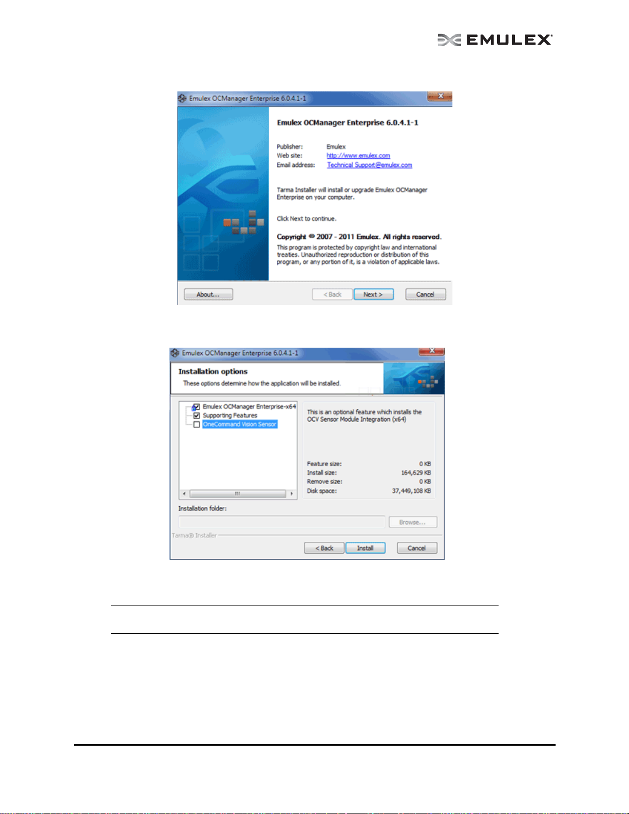
3. Double click the elxocm<version>.exe. The Emulex OCMan ager En terprise window app ears.
Figure 1: OCManager Enterprise window
4. Click Next. The Installation Options window appears.
Figure 2: OCManager Enterprise Installation Options window
5. Check the applications that you want to install and click Install.
Note: You can also install the OneCommand Vision Sensor, but you must have the
Windows SNMP service installed or the sensor installation will fail.
The OneCommand Manager User Manual Page 5
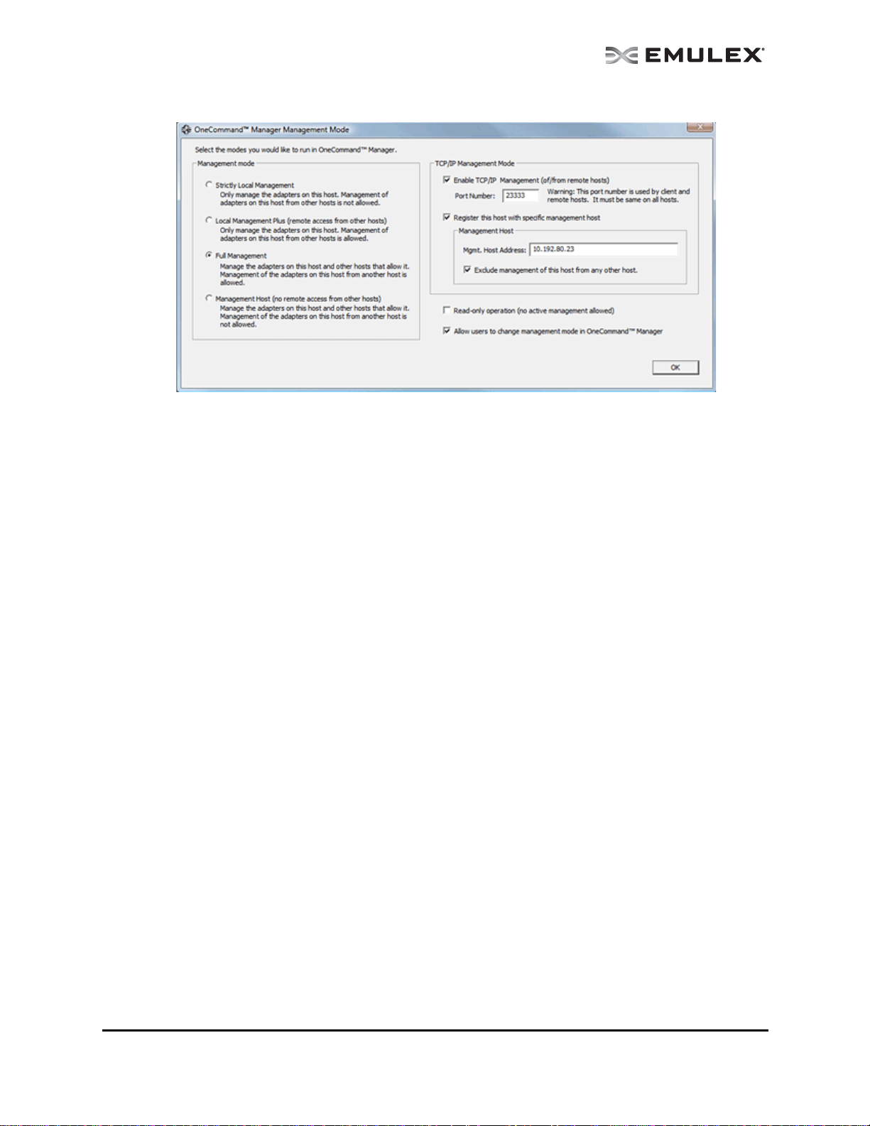
Figure 3: Management Mode dialog box
6. During installation the Management Mode dialog box appears. Ch oose the ma nagement mod e
you want and click OK. See “Changing Management and Read-Only Mode” on page 28 for more
information about configuring management mode.
7. Check or uncheck the Enable TCP/IP Manageme nt checkbox to en able or disable rem ote
management over TCP/IP. You can also change the TCP/IP port used (23333 is the IANA
registered port for Emulex).
8. The Installation Completed window appears when the installation is finished. Click Finish. A
shortcut is added to the Start menu. You do not need to reboot the system.
The OneCommand Manager User Manual Page 6

Unattended Installation in Windows
To install the OneCommand Manager application in Windows:
1. From the Emulex website, download the x64 or x86 OneComm and Man ager En terprise Kit
installation file to your system.
The kit is activated with the optional switch /q or /q2. The /q switch displays progress reports.
The /q2 switch does not display progress reports.
You must select a Management Mode by adding the mmode argument and the ability to change
that Management Mode by adding the change argument with selected values as in the example
below.
For example at the command prompt type:
elxocm-windows-x86-5.01.00.10-4.exe mmode=3 achange=1 /q2
The following are the possible mmode values:
1. Local Only Management Mode
2. Local Plus Management Mode
3. Full Management Mode
4. Local Plus Management Mode and Read Only
5. Full Management Mode and Read Only
6. Management host
The following are the possible achange values:
0. Do not allow Management Mode to change
1. Allow Management Mode to change
2. You can also set the following optional parameters:
• MHost - This option al switch allows a non-mana gement-ho st user to se lect a Ma nagemen t
Host with which to register. If this switch is not specified, the default value of 0 will be used
and the feature will be disabled. If the switch is specified, the value can be a host name or
an IP address which will be validated by the installer. An error message appears if /mmode
is set as Local Only or Management Host.
• excl - This op tional switch allows the non-man agemen t-host user to select whe ther it will
process requests exclusively from the Management Host specified by the MHost switch.
This option is only accepted if accompanied by a valid MHost value; otherwise an error
message appears. If this switch is not specified, the default value of 0 will be used. If the
switch is specified, the valid values are as follows:
0. Remotely managed by other hosts.
1. Remotely man aged by M anageme nt Host ONLY
• Mtcp - This option al switch allows you to ena ble or disable remo te manag ement and to
specify the TCP/IP port number over which management will occur. If this switch is not
specified, the default TCP/IP port number 2333 will be used.
If the management host option is selected, you must either select the default port number or
enter a valid TCP/IP port number on the command line. A value of 0 will not be accepted.
If one of the non-management host options is selected, the TCP/IP port number may be
entered on the command line.
The OneCommand Manager User Manual Page 7

In Solaris
The following must be installed for the utilities to function properly:
• The Solaris FC/FCoE inbox driver version 2.60 or later or the out of box driver version elxfc
4.00.xx.xx must be installed for FC/FCoE management.
• The NIC inbox driver version OCe1.20 or later or the out of box driver version 4.00 must be
installed for UCNA management.
Note: If Emulex OneConnect UCNAs are installed on the system, the NIC driver must be
installed and reporting all NIC ports. Otherwise, the OneCommand Manager
application cannot manage UCNAs.
To install the OneCommand Manager application in Solaris:
1. Copy the Solaris utility kit to a temporary directory on your system.
2. Untar the utility kit:
tar xvf elxocm-solaris-<version>.tar
3. Change to the newly created elxocm-solaris-<versio n> directory:
cd ./elxocm-solaris-<version>/
4. Execute the install script to begin installation. If the HBAnyware utility, OneCommand Manager
Core or OneCommand Manager Enterprise applications or the Solaris driver utilities are already
present on the system, the install script attempts to remove them first:
./install
5. When prompted, choose whether or not to install the OneCommand Vision Sensor:
Would you like to install the OneCommand Vision Sensor kits along with
this installation?
Enter y to install the kit.
Enter n not to install the kit. (default)
Enter the letter 'y' or 'n' y
6. When prompted, enter the type of management you want to use:
Enter the type of management you want to use:
1 Local Mode : HBA's on this Platform can be managed by OneCommand
clients on this Platform Only.
2 Managed Mode: HBA's on this Platform can be managed by local or
remote OneCommand clients.
3 Remote Mode : Same as '2' plus OneCommand clients on this Platform
can manage local and remote HBA's.
4 Management Host : Same as '1' plus OneCommand clients on this Platform
can manage remote HBA's.
If you select option 2, you are asked if you want to enable TCP/IP management from remote
hosts.
If you select option 3, you are asked if you want to enable TCP/IP management of/from remote
hosts. You are prompted to enter the TCP/IP port number to use. (Leaving the field blank
defaults to 23333.)
If you select options 2 or 3, you are prompted for the managment host address. (Leaving the
field blanks means none.)
You can enter an IP address or host name. If you enter a management host address, you will be
prompted to exclude management of this host from any other host.
The OneCommand Manager User Manual Page 8

If you select option 4, management of remote hosts is automatically selected and you are
prompted to enter the TCP/IP port number to use. (Leaving the field blank defaults to 23333.)
Note: Management hosts cannot be managed by remote hosts
7. If you answered 2, 3 or 4 in step 5, you must de cide if yo u want the One Command Manager
application to operate in read-only mode. Read-only mode preven ts users from performing
certain operations such as resetting adapters, updating an adapter's firmware and changing
adapter driver properties and bindings. It only affects the local OneCommand Manager
application interface. These operations can still be performed using remote management. Enter
<y> for yes to allow the user to perform these operations, enter <n> for no if read-only mode is
desired.
8. You are prompted about allowing users to change the management mode after installation.
Enter <y> for yes, or <n> for no.
In Linux
The following must be installed before you can install the OneCommand Manager application:
• The appropriate driver for your operating system:
• Linux drive r version 8.2.0.33 .3p or later (Fo r RHEL5 an d SLES10 op erating systems.)
• Linux drive r version 8.3.5.X or later (For RHEL 6 SLES 11 SP1 operating systems.)
Note: The RHEL 6 Enterprise kit requires the intallation of the libstdc++-5.so library. This
library is available through the compat-libstdc++-33 -3.2.3-68.<arch>.rpm or later . The
PPC and x86_64 builds require the 64bit version installed which is installed in
/usr/lib64.The i386 build requires the 32bit version installed which is installed in
/usr/lib.
• Previous versions of the Linux driver must be uninstalled. You must run the uninstall script that
shipped with the version of the Linux driver you want to remove.
To install the OneCommand Manager application in Linux:
1. Log on as ‘root’.
2. Download the utilities from the Emulex website or cop y them from th e installation CD.
3. Copy the installation and uninstallation scripts to a known location, for easy access by other
users.
4. Copy the OneCommand elxocm-<Platform>-<AppsRev>.tgz file to a directory on the install
machine.
5. Change to the directory to which you copied the tar file.
6. Untar the file.
• For RHEL 5 and RHEL 6 type:
tar zxvf elxocm-rhel5-rhel6-<apps_ver>-<rel>.tgz
• For SLES 10 and SLES 11 type:
tar zxvf elxocm-sles10-sles11-<apps_ver>-<rel>.tgz
7. Change to the elxocm directory created in step 6.
• For RHEL 5 and RHEL 6 type:
cd elxocm-rhel5-rhel6-<apps_ver>-<rel>
• For SLES 10 and SLES 11 type:
cd elxocm-sles10-sles11-<apps_ver>-<rel>
The OneCommand Manager User Manual Page 9

8. Run the install script. Type:
./install.sh
9. When promted, choose whether or not to install the OneComm and Vision Sensor:
Would you like to install the OneCommand Vision Sensor kits along with
this installation?
Enter y to install the kit.
Enter n not to install the kit. (default)
Enter the letter 'y' or 'n' y
10. When prompted, enter the type of management you want to use:
Enter the type of management you want to use:
1 Local Mode : HBA's on this Platform can be managed by OneCommand
clients on this Platform Only.
2 Managed Mode: HBA's on this Platform can be managed by local or
remote OneCommand clients.
3 Remote Mode : Same as '2' plus OneCommand clients on this Platform
can manage local and remote HBA's.
4 Management Host : Same as '1' plus OneCommand clients on this Platform
can manage remote HBA's.
If you select option 2, you are asked if you want to enable TCP/IP management from remote
hosts.
If you select option 3, you are asked if you want to enable TCP/IP management of/from remote
hosts. You are prompted to enter the TCP/IP port number to use. (Leaving the field blank
defaults to 23333.)
If you select options 2 or 3, you are prompted for the management host address. (Leaving the
field blanks means none.)
You can enter an IP address or host name. If you enter a management host address, you will be
prompted to exclude management of this host from any other host.
If you select option 4, management of remote hosts is automatically selected and you are
prompted to enter the TCP/IP port number to use. (Leaving the field blank defaults to 23333.)
Note: Management hosts cannot be managed by remote hosts
11. If you answered 2, 3 or 4 in step 5, you must decide if you want the OneComm and Man ager
application to operate in read-only mode. Read-only mode preven ts users from performing
certain operations such as resetting adapters, updating an adapter's firmware and changing
adapter driver properties and bindings. It only affects the local OneCommand Manager
application interface. These operations can still be performed using remote management. Enter
<y> for yes to allow the user to perform these operations, enter <n> for no if read-only mode is
desired.
12. You are prompted about allowing users to change the manage ment mod e after installation.
Enter <y> for yes, or <n> for no.
In VMware ESX Server
For the best real-time management of Emulex adapters in VMware ESX and ESXi environments, the
OneCommand Manager for VMware vCenter software plug-in (OCM for VMware) is h ighly
recommended. For more information and to down load go to
http://www.emulex.com/products/software-solutions/device-management/onecommand-manager-forvmware/overview.html.
The following must be installed before you can install the OneCommand Manager application:
The OneCommand Manager User Manual Page 10

• Emulex Driver for VMware ESX, ver sion 8.2 o r la ter is require d only if FC/FCoE functionality is
desired. Refer to the Emulex Driver for VMware ESX User Manual for specific information on
driver support in ESX Releases.
• The NIC driver is required only if FCoE/iSCSI/NIC functionality is desired.
• The iSCSI driver is required only if iSCSI functionality is desired. (ESX 4.1 or later)
To install the OneCommand Manager application agent in VMware ESX Server:
1. Log into the ESX Server COS.
2. Copy the elxocmcore-esx<NN>-<version>.<arch>.rpm file to a directory on the install machine,
where NN is 40 for ESX 4.0, 41 for an ESX 4.1 or 50 for an ESXi 5.0 system.
3. CD to the directory to which you copied the rpm file.
4. Install the rpm. Type:
rpm -Uvh elxocmcore-esx<NN>-<version>.<arch>.rpm
Where NN is 40 for ESX 4.0, 41 for an ESX 4.1 or 50 for an ESXi 5.0 system. The rpm contents
are installed in /usr/sbin/ocmanager. The OneCommand Manager application Command Line
Interface is also located in this directory.
Installing the OneCommand Manager Application Web Launch Interface
Prerequisites
In addition to the driver and OneCommand Manager application, the following prerequisites must be met
before you install the Web Launch feature:
Note: The OneCommand Manager application Web Launch Interface is not supported on
VMware ESX Server.
In Windows:
• Microsoft Internet Information Services (IIS) Server must be installed. See the Microsoft
website for information on downloads and installation.
• The Win dows Firewall fea ture m ay be enab led by de fault. If it is, you must ad d and enable
three exceptions: HTTP port, java.exe and rmiregistry.exe.
Note: Allowing programs and/or ports through the firewall may increase the security risks.
Use at your own discretion.
To enable the HTTP port:
1. Click Add Port... The Add a Port dialog box is displayed.
2. On the Add a Port dialog box, type HTTP as the Name and 80 as the Port Number.
3. Leave TCP enabled and click OK.
To enable the java.exe program:
1. Click Add Program... The Add a Program dialog box is displayed.
2. Click Browse...
3. Specify java.exe located in the OneCommand Manager JRE installation path. For
example: C:\Program Files\Emulex\util\JRE\bin\java.exe.
4. Click OK.
The OneCommand Manager User Manual Page 11

To enable the rmiregistry.exe program:
1. Click Add Program...The Add a Program dialog box is displayed.
2. Click Browse... and specify the rmiregistry.exe located in the OneCommand Manager
JRE installation path. For example:
C:\Program Files\Emulex\util\JRE\bin\rmiregistry.exe.
3. Click OK.
4. Click OK to apply the new firewall settings.
To add the MIME type:
1. Launch Server Manager.
2. Expand Roles.
3. Under Roles, expand Web Server (IIS).
4. Under Web Server (IIS), Click Internet Information Services (IIS) Manager.
5. In the right pane, find your server name under "Start Page" and click on it.
6. Double-click MIME Types listed under IIS group.
7. A MIME Types page appears. Under "Actions", click Add... A popup dialog box appears.
8. Add "jnlp" (without quotes) to the File name extension field.
9. Add "application/x-java-jnlp-file" (without quotes) to the MIME type field.
10. Click OK.
In Solaris and Linux:
• Apache Web server must be installed and running on the server tha t is hostin g the Web
Launch Service software.
• The Java Web Start application must be installed and running on the browser host.
The server on which you are installing the Web Launch Service package requires:
• An HTTP server configured to handle the JNLP MIME file type. The following MIME file type/
file extension must be added to your server configuration:
• The HTT P server must be ru nning.
The client on which you are running the browser requires:
• Java m ust be installed. The specific requir ements are:
• Sun 32 -bit Java 6.0 or later fo r Intel base d systems (x86 an d IA64)
• 32-bit Java 6.0 or later for x86-64 systems
• 32- bit Java 6.0 o r later for RHEL 5 and SLES 10 (ppc64)
Refer to the appropriate vendor documentation for detailed instructions about configuring MIME
types, configuring and starting the HTTP server and installing the JRE. See
/opt/ELXocm/README_WEBLAUNCH.txt (Solaris) or
/usr/sbin/ocmanager/README_WEBLAUNCH.txt (Linux) for more setup information.
Procedures
MIME type: application/x-java-jnlp-file
File Extension: jnlp
To install the OneCommand Manager application Web Launch Interface:
In Windows (Windows Server 2003, Windows Server 2008 and Windows Server 2008 R2):
1. Click Programs>Emulex >OCManager WebLaunch Install. Web Launch installation begins.
The OneCommand Manager User Manual Page 12

In Solaris and Linux:
1. Log on as ‘root’.
2. Navigate to the OneCommand Mana ger directory.
• Solaris:
cd /opt/ELXocm
• Linux:
cd /usr/sbin/ocmanager
3. Run the install script. Type:
./wsinstall
4. When prompted, enter the web server's docume nt root dir ectory. For example:
• Solaris:
/var/apache/htdocs
• Linux:
/srv/www/htdocs
or
/var/www/html
5. Confirm that the IP address of the host is the IP address that the web server uses. Answer <y>
or <n> as appropriate. If you answer <n>, you are prompted for the IP address you want to use.
6. When asked if your web server is listening on the normal default HTTP port (80), answer <y> or
<n> as appropriate. If you answer <n>, you are prompted for the port you want to use.
Once you have entered the necessary information, you are notified when the installation of the
OneCommand Manager application Web Launch package is complete. The Web Launch configuration files are created and Web Launch Service automatically starts.
7. To verify the installation, locate another client, open a web browser window a nd enter the
following URL:
http://IP_ADDR:PORT_NUM/ocmanager.jnlp
where IP_ADDR is the IP address of the host on which you installed the OneCommand Manager
application Web Launch service, and PORT_NUM is the TCP port number of the listening host’s
web server. The standard OneCommand Manager application user interface appears.
Note: It is not necessary to enter a port number if the standard HTTP port was chosen
during configuration.
Installing the OneCommand Manager Application Command Line Interface
The OneCommand Manager application Command Line Interface (CLI) is a compreh ensive
management utility for Emulex host bus adapters (HBAs) and converged network adapters (C NAs) that
provides support for commonly used commands without requiring installation of the OneCommand
Manager application GUI. The OneCommand Manager ap plication CLI can be installed separately
without installing the OneCommand Manager application GUI. The OneCommand Manager CLI console
application, named hbacmd, can be installed on Windows, Solaris, Linux and versions of VMware ESX
Server that include a Console Operating System (COS). A single operation is performed by entering
’hbacmd’ followed by the command at the command line. For syntax information and details on using the
OneCommand Manager application CLI, see “Using the OneCo mm and Ma nager Application Command
Line Interface” on page 187.
Note: If you installed the OneCommand Manager application, the CLI is already installed.
The OneCommand Manager User Manual Page 13
In Windows
There are two ways to install the OneCommand Manager application CLI in Windows:
• Attended installation using the GUI.
• Unattended installation using the command line.
Attended Installation in Windows
To install the OneCommand Manager application CLI:
1. From the Emulex website, download the x64 or x86 OneCommand Manager Core Kit installation
file.
Note: For IA64 systems, use the x86 OneCommand Manager Core Kit installation file.
2. Navigate to the system directory where you download the file.
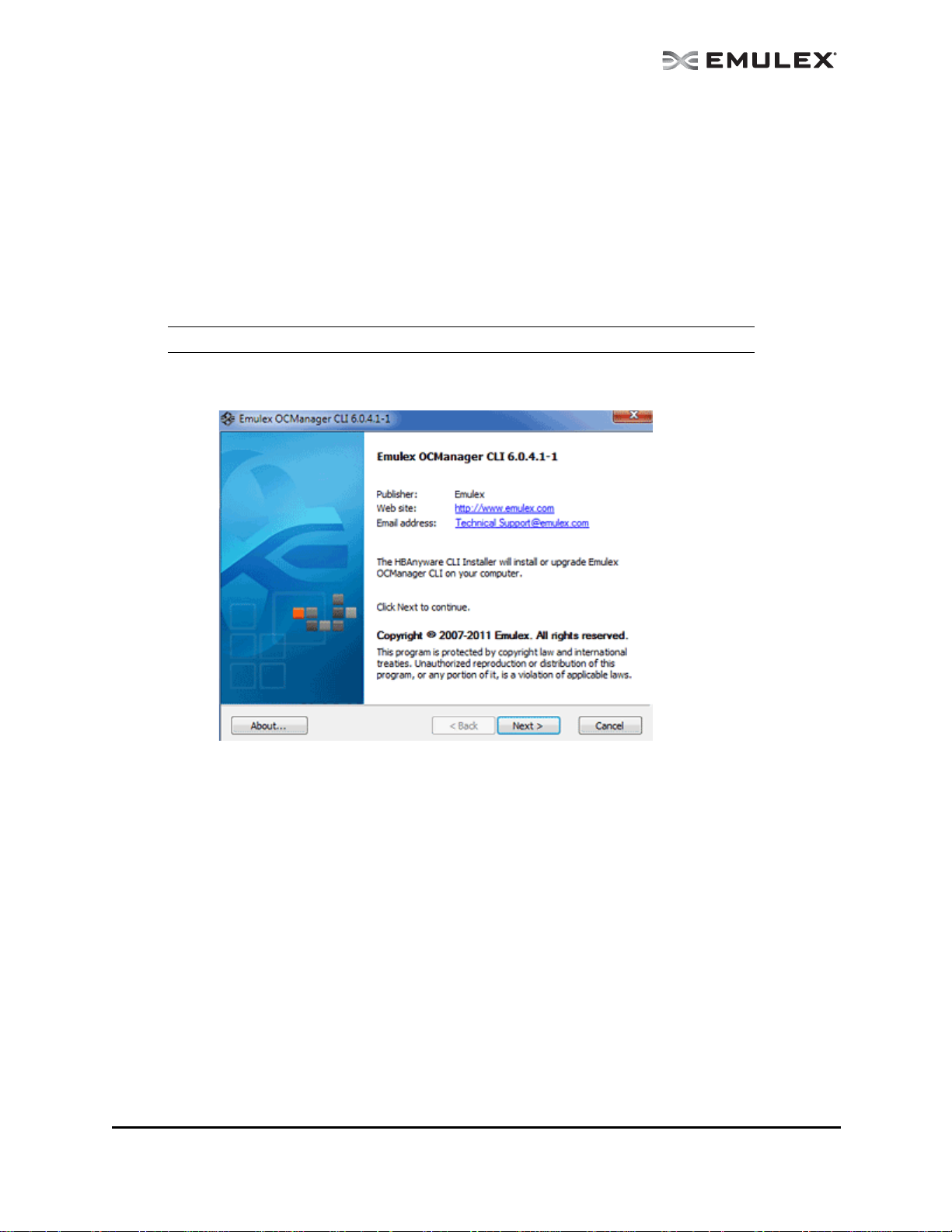
3. Double click the elxocmcore<version>.exe. The Emulex OCManager CLI wind ow appears.
Figure 4: OCManager CLI window
The OneCommand Manager User Manual Page 14
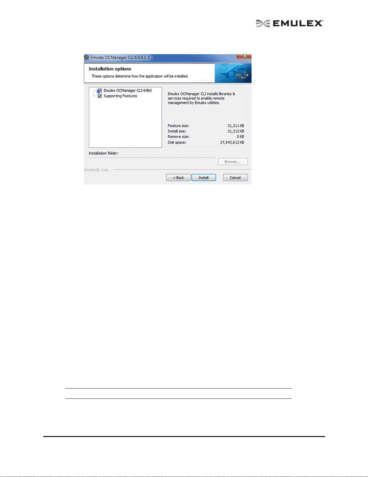
4. Click Next. The Installation options window appears.
Figure 5: OCManager CLI Installation options window
5. Click Install. The Operation in Progress window appears. The Installation completed window
appears when the installation is finished.
6. Click Finish. You do not need to reboot the system.
Unattended Installation in Windows
To install the OneCommand Manager CLI application in Windows:
1. From the Emulex website, download the x64 or x86 OneCommand Manager Core Kit installation
file to your system.
2. At the command prompt, set the optional switch to /q or /q2. The kit is activated with this optional
switch. The /q switch displays some progress reports. The /q2 switch does not displa y prog ress
reports.
For example:
elxocmcore-windows-x64-5.01.00.10-4.exe /q2
In VMware ESX Server
To install the OneCommand Manager application CLI on a new system, install the specific rpm file for the
driver for your VMware version.
Prerequisites
• To manage FCoE adapters, load LPFC driver version 8.2, or later.
• To manage NIC or iSCSI adapters, load driver version 2.102.440.0, or later.
• To manage iSCSI adapters, load the iSCSI driver.
Note: The iSCSI driver is not supported for VMware ESX 4.0.
Procedures
To install the OneCommand Manager application CLI:
The OneCommand Manager User Manual Page 15

1. Log into the ESX Server Host COS.
2. Copy the elxocmcore-esxNN-<kit version>.<arch>.rpm file to a directory on the install machine.
3. Change to the directory to which you copied the rpm file .
4. Install the rpm file. Type:
rpm -Uvh elxocmcore-esxNN-<kit version>.<arch>.rpm
Where NN is 40 for an ESX 4.0 system or 41 for an ESX 4.1 system. The rpm contents are
installed in /usr/sbin/ocmanager. The OneCommand Manager application CLI is also located in
this directory.
In a VMware ESX Server with an Existing HBAnyware CLI Kit Installed
To install the OneCommand Manager application CLI on a VMware system with an existing HBAnyware
CLI installed:
1. Install the rpm file by entering the following command all on one line at th e com and prom pt:
# rpm -Uvh elxocmcore-esxNN-<kit version>.<arch>.rpm
Where NN is 40 for ESX 4.0, 41 for an ESX 4.1 or 50 for an ESXi 5.0 system.
Uninstalling Older HBAnyware Kits on VMware
To uninstall an older HBAnyware Kit on VMware:
1. Log into the ESX Server COS.
2. Type: rpm -qa | grep elx and locate either of the following rpm files:
elxvmwarecorekit-<kit version>
Or
elxocmcore-esxNN-<kit version>
Where NN is 40 for ESX 4.0, 41 for an ESX 4.1 or 50 for an ESXi 5.0 system.
3. Type:
rpm -e elxvmwarecorekit-<kit version>
Or
rpm -e elxocmcore-esxNN-<kit version>
Where NN is 40 for ESX 4.0, 41 for an ESX 4.1 or 50 for an ESXi 5.0 system.
In Linux
Prerequisites
For existing systems install the following drivers before installing the OneCommand Manager application
CLI:
On LP21000 series adapters and OneConnect FCoE adapters:
• Linux driver version 8.2.0.33.3p or later (For RHEL5 and SLES10 operating systems.)
• Linux driver version 8.3.5.X (For RHEL6 and SLES 11 SP1 operating systems.)
Note: The RHEL 6 Enterprise kit requires the intallation of the libstdc++-5.so library. This
library is available through the compat-libstdc++-33 -3.2.3-68.<arch>.rpm or later . The
PPC and x86_64 builds require the 64bit version which is installed in
/usr/lib64.The i386 build requires the 32bit version which is installed in
/usr/lib.
The OneCommand Manager User Manual Page 16

On OneConnect iSCSI adapters:
• iSCSI driver
On OneConnect NIC adapters:
• NIC driver
Note: The NIC driver must also be installed if the adapter personality is iSCSI-NIC or
FCoE-NIC.
• Use the latest or matching driver from the Emulex website.
For new systems, the specific driver rpm file for your Linux version must be installed.
Note: On RHEL 5.5, RHEL 5.6 and RHEL 6, the OneCommand Core rpm file requires the
“Libnl” library. This library is not installed by default, but can be obtained from the OS
distribution media.
• For i386 RHEL 5.5, RHEL 5.6 and RHEL 6, use the 32bit libnl library.
• For x86_64 RHEL 5.5, RHEL 5.6 and RHEL 6, use the 64bit libnl library.
• For ia64 RHEL 5.5, RHEL 5.6 and RHEL 6, use the 64bit libnl library.
• For PPC RHEL 5.5, RHEL 5.6 and RHEL 6, use the 32bit libnl library.
Procedures
To install the OneCommand Manager application CLI:
1. Copy the applications kit tar file to a directory on the installation machine.
2. Change to the directory where you copied the tar file.
3. Untar the file.
tar zxvf elxocmcore-<supported_os>-<app_ver>-<rel>.tgz
4. Change (use cd command) to the core kit dir ectory created in ste p 3.
cd elxocmcore-<supported_os>-<app_ver>-<rel>
5. Run the install.sh script.
./install.sh
Note: The core kit consists of 2 rpm files for each supported architecture and each
supported version of Linux:
1. elxocmlibhbaapi-*.rpm
2. elxocmcore-*.rpm
In a Linux System with an Existing HBAnyware CLI Kit Installed
Note: The OneCommand Manager application core kit cannot be installed if a previous
version of HBAnyware is installed.
You have two options when installing the OneCommand Manager application CLI on a Linux system:
• Upgrade - preserve existing settings
• Clean install - overwrite existing settings
To upgrade:
1. You must install the current core kit as detailed in “In Linux” on page 16.
The rpm file handles the configuration file upgrade.
The OneCommand Manager User Manual Page 17

The install script executes an rpm upgrade (rpm -U *.rpm) to upgrade the installed version of the
core kit to the current version.
Note: There is no upgrade path from an HBAnyware 4.x or 3.x core kit to a OneCommand
Manager application 5.2.0.x core kit. You must uninstall previous versions of the
HBAnyware utility before installing a OneCommand Manager app lication core kit. For
information on uninstalling older versions of HBAnyware, see “Uninstalling Older
HBAnyware Kits on Linux” on page 18.
To perform a clean install:
1. Uninstall the existing OneCommand Manager application CLI using the uninstall script included
in the tar file or in /usr/sbin/ocmanager/scripts directory.
Note: If an HBAnyware CLI or enterprise kit is installed, follow the procedure for
“Uninstalling Older HBAnyware Kits on Linux” on page 18.
Note: Your configuration files are backed up by rpm with an .rpmsave extension.
2. Install the specific rpm file for your driver for Linux version. Fo r inform ation o n installing the rpm
file, see “In Linux” on page 16.
Uninstalling Older HBAnyware Kits on Linux
Uninstalling an older HBAnyware core kit:
1. Run the following command to remove the core kit.
rpm -e elxlinuxcorekit
Uninstalling an older HBAnyware enterprise kit:
1. Run the uninstall script located in /usr/sbin/hbanyware/scripts to remove the enterprise kit.
Or
Run the uninstall script located in the tar file to remove the enterprise kit.
If the HBAnyware Security Configurator is installed, it must be uninstalled before uninstalling the
HBAnyware utility. You must run the uninstall script that shipped with the version of HBAnyware
Security Configurator that you want to remove. Proceed to step 2. If the Security Configurator is
not installed, proceed to step 3.
2. If the HBAnyware Security Configurator is installed, follow these ste ps:
a. Log on as ‘root’.
b. Change to the directory to which you copied the tar file.
c. Extract the tar file using the tar -xvf command.
d. Change to the newly created directory.
e. Run the uninstall script with the ssc parameter specified. Type:
./uninstall ssc
3. Uninstall the HBAnyware utility and the Application Helper Module:
a. Log on as ‘root’.
b. Change to the directory to which you copied the tar file.
c. Extract the tar file using the tar -xvf command.
d. Change to the newly created directory.
e. Uninstall any previously installed versions. Type:
./uninstall
The OneCommand Manager User Manual Page 18

In Solaris
Prerequisites
• The Solaris FC/FCoE driver version 2.60 or later must be installed for FC/FCoE management.
• The NIC driver version 1.20 or later must be installed for UCNA management.
Note: If Emulex OneConnect UCNAs are installed on the system, the NIC driver must be
installed and reporting all NIC ports. Otherwise, the OneCommand Manager
application cannot manage UCNAs.
Procedures
To install the OneCommand Manager application CLI:
1. Copy the OneCommand Manager application core kit to a tempo rary directory on the system.
2. Untar the core kit. Type:
tar xvf elxocmcore-<kit version>.tar
3. Change to the newly created elxocmcore-<kit version> directory:
cd ./elxocmcore-<kit version>/
4. Run the install script and follow the instructions.
./install
If the HBAnyware utility, the OneCommand Manager application cor e kit, the One Command
Manager application enterprise kit, or the Solaris driver utilities are already present on the system, the install script attempts to first remove them.
Upgrading from the OneCommand Manager Application CLI to the FullFeatured OneCommand Manager Application Enterprise Kit
Note: An upgrade can be performed only if the version of the OneCommand Manager
application enterprise kit is the same or later than the OneCommand Manager
application CLI version. You cannot downgrade a OneCommand Manager application
CLI with a previous version of the OneCommand Manager application enterprise kit.
Note: When the OneCommand Vision Sensor software is installed on production servers
with Emulex adapters installed, the Sensor software may load and use some of the
software components included in the OneCommand Manager application or
HBAnyware utility software stacks. It is essential that the OneCommand Vision
Sensor software be stopped before performing any upgrades, or updates, to the
OneCommand Manager application or HBAnyware software stack components. For
information on stopping the Sensor, refer the OneCommand Vision user manual.
In Windows
To upgrade from the OneCommand Manager application CLI to the full-featured OneCommand Manager
application kit:
1. From the desktop, run the elxocm-windows-<kit version>.ex e file that con tains the full
application kit.
Running this executable file removes the OneCommand Manager application CLI and installs a
full-featured version of the OneCommand Manager application that includes the CLI and the
GUI.
The OneCommand Manager User Manual Page 19

In Linux
To upgrade from the OneCommand Manager application CLI to the full-featured OneCommand Manager
application kit:
1. Run the install.sh script of the OneCommand Manager application enterprise kit.
The install script executes an rpm upgrade (rpm -U *.rpm) to upgrade the installed core kit to an
enterprise kit.
In Solaris
To upgrade from the OneCommand Manager application CLI to the full-featured OneCommand Manager
application kit:
1. Download the OneCommand Manager application enterprise kit to a temporary directory on your
system.
2. Untar the OneCommand Manager application enterprise kit tar file:
tar xvf elxocm-<kit version>.tar
3. Change to the newly created elxocm-<kit version> directory:
cd ./elxocm-<kit version>/
4. Run the install script and follow the instructions.
./install
In VMware ESX Server
The full-featured OneCommand Manager application kit is not supported for VMware ESX Server.
Uninstalling the OneCommand Manager Application
Note: Do not uninstall the OneCommand Manager application if you are running, or intend
to run, OneCommand Vision.
Note: Uninstalling the OneCommand Manager application also uninstalls the
OneCommand Vision application.
To uninstall the OneCommand Manager application and OneCommand Manager application Web
Launch Interface:
In Windows
1. (Windows 2003) Select Start>Control Panel>Add/Remove Programs.
or
(Windows 2008 & Windows 2008 R2) Select Start>Control Panel>Programs>Uninstall a Pro-
gram.
2. If present, select Emulex Common SAN Manage ment [vers ion] and click Remove or
Uninstall. Click Yes. The Emulex Common SAN Management components are removed from
the system.
3. Select Emulex OCManager Enterprise [version] or Emu lex OC Manager CL I [version] an d
click Remove or Uninstall.
The OneCommand Manager User Manual Page 20

In Solaris
Note: If you installed the OneCommand Manager application Web Launch Interface, you
must uninstall it before uninstalling the OneCommand Manager application. See
“Uninstalling the OneCommand Manager Application Web Launch Interface Only” on
page 21.
1. Log on as ‘root’.
2. Run the OneCommand Manager un install script:
/opt/ELXocm/scripts/uninstall
In Linux
Note: If you installed the OneCommand Manager application Web Launch Interface, you
must uninstall it before uninstalling the OneCommand Manager application. See
“Uninstalling the OneCommand Manager Application Web Launch Interface Only” on
page 21.
1. Log in as ‘root’.
2. Change to the elxocm-<platform>-<version> installation directory.
3. Type:
./uninstall
In VMware
1. Log in as 'root'.
2. Type:
rpm -e elxocmcore-esxNN-<version>
Where NN is 40 for ESX 4.0, 41 for an ESX 4.1 or 50 for an ESXi 5.0 system.
Uninstalling the OneCommand Manager Application Web Launch Interface Only
To uninstall the OneCommand Manager application Web Launch, but leave the OneCommand Manager
application installed:
In Windows:
1. Select Start>Programs>Emulex>OCManager WebLaunch Uninstall. The following screen
appears:
Figure 6: OneCommand Manager Web Launch U ninstallation scr een
The OneCommand Manager User Manual Page 21

2. The OneCommand Manager application Web Launch Interface is re moved. Press any ke y to
continue.
In Solaris and Linux:
1. Log on as ‘root’.
Note: If you installed the OneCommand Manager application Web Launch Interface, you
must uninstall it before uninstalling the OneCommand Manager application.
2. Execute the uninstallation script.
• Solaris:
/opt/ELXocm/wsuninstall
• Linux:
/usr/sbin/ocmanager/wsuninstall
This script stops the OneCommand Manager application Web Launch Interface service daemons (if they
are running) and removes all Web Launch related files from the host.
Starting and Stopping the OneCommand Manager Application
In Windows:
To start the OneCommand Manager application:
1. On the Windows desktop, select Start>All Programs>Emulex>OCManager.
To stop the OneCommand Manager application:
1. From the OneCommand Manager app lication sele ct File>Exit.
In Linux and Solaris:
On Linux and Solaris machines, you can stop and start the OneCommand Manager daemon processes
using the "stop_ocmanager" and "start_ocmanager" scripts respectively. These are found in the
following OneCommand Manager installation directory:
Linux - /usr/sbin/ocmanager
Solaris - /opt/ELXocm
There are three basic daemon processes, included with OneCommand Ma nager installations, that are
affected by these scripts. They are:
• elxhbamgrd - Remote management daemon which services reque sts from OneCommand
Manager clients running on remote host machines.
• mili2d - MILI daemon that routes major po rtio ns o f the local On eCommand Manager client CNA
management requests.
• elxdiscoveryd - Discovery daemon responsible for maintaining all discovery data (remote and
local) for OneCommand Manager clients running on the local machine.
elxhbamgrd and mili2d start at system boot time. elxdiscoveryd starts whenever the OneCommand
Manager GUI process first runs on the host machine.
Additionally if the web-launch component of OneCommand Manager is installed, the daemon process,
rmiserver, starts at system boot time. The start_weblaunch script starts this daemon, while the
stop_weblaunch stops it.
The OneCommand Manager User Manual Page 22

Starting the OneCommand Manager Application Web Launch Interface
After the OneCommand Manager application Web Launch Interface software is installed and the Web
Launch server is initialized, you can launch the OneCommand Manager app lication directly with your
Web browser.
Note: Only the OneC ommand Manager application GUI is e xported to the requesting cl ient.
All adapter discovery and remote management operations are performed by
resources running on the remote host that served the GUI component. The refore, th e
SAN view displayed by the GUI is not from the client running the GUI, but rather from
the host from which this GUI was retrieved.
To launch the OneCommand Manager application with your Web browser:
1. Open your web browser. Linux and Solaris users must log on as ‘root’.
2. Enter the URL of the ocmanager.jnlp file. Make sure that the URL specifies a remote server
which has the OneCommand Manager application Web Launch Interface software installed and
running.
http://IP_ADDR:PORT_NUM/ocmanager.jnlp
where IP_ADDR is the IP address of the host on which you installed the OneCommand Manager
Web Launch Service, and PORT_NUM is the TCP port number of the listening hosts' Web
server. If the port number is omitted, the default port 80 is used. The standard OneCommand
Manager application user interface is displayed.
Managing Files when Running the OneCommand Manager Application Web Launch Interface
When running the OneCommand Manager application Web Launch Interface, all files (lo g files, drive r
parameter files, firmware files, etc.) are located on the browser launch h ost , whi ch is n ot ne cessa rily th e
same as the remote host that is specified in the Web Launch address.
The OneCommand Manager User Manual Page 23

Using the OneCommand Manager Application
Note: To properly view the OneCommand Manager application, ensure your system meets the
following display requirements:
For Windows systems, the display resolution must be set to 800 by 600 or better.
For Linux and Solaris systems, the display resolution must be set to 1024 by 768 or better.
The display must run in 256-color mode or higher. OneCommand Manager application icons
use 256 colors. If the display is set for 16 color mode, OneCommand Manager application
icons are not displayed.
The OneCommand Manager Application Window Element Definitions
The OneCommand Manager application window contains five basic components: the menu bar, the
toolbar, the discovery-tree, the property tabs and the status bar.
Figure 7: OneCommand Manager ap plicat ion windo w
Note: The element you select in the discovery-tree determines whether a menu item or
toolbar icon is active. For example, if you select the local host or other system host,
the Reset Adapter item on the Adapter menu is unavailable. The Reset Adapter
toolbar button is unavailable as well.
Note: Screenshot s in this manual are fo r illustrati ve purposes only. Your system information
can vary.
Note: The features displayed by your local OneCommand Manager application interface will
match those of the remote server. When accessing a remote server running an older
version of the OneCommand Manager application, features that are not supported by
the server’s older version of the OneCommand Manager application are unavailable.
Note: In some instances, the type of information displayed and available functionality is
determined by the operating system in use.
The OneCommand Manager User Manual Page 24

The Menu Bar
The menu bar contains commands that enable you to perform a variety of tasks such as exiting the
OneCommand Manager application, resetting adapters and sorting ite ms in the discovery-tree view.
Many of the menu bar commands are also available from the toolbar.
The Toolbar
The toolbar contains buttons that enable you to refresh the discovery-tree, reset the selected adapter
and choose how you want to view discovered SAN elements in the discovery-tree. Many of the toolbar
functions are also available from the menu bar.
Figure 8: Toolbar
The toolbar is visible by default. Use the Toolbar item in the View menu to h ide the toolba r. If the item is
checked, the toolbar is visible.
The Toolbar Buttons
The toolbar buttons perform the following tasks:
Discovery Refresh button
• Initiates a discovery refresh cycle.
Reset button
• Resets the selected adapter.
The View Buttons on the Toolbar
The View buttons on the toolbar enable you to view SAN el ement s from the ho st, fabric, virtual p ort s, or
by local or remote adapter perspective. By default, both local and remote adapters are displayed in
Host view. The OneCommand Manager application displays elements in ascending order.
Host View button (default)
• Displays the host system.
Note: Y ou cannot change host names using th e OneCommand Manager application; names
must be changed locally on that system.
• Displays the installed adapters within each host system.
• Displays adapter ports and the port numbers if available.
• Displays adapters by the WWNN if multiple adapters have the same model number.
• Displays the WWPN if targets are present. Multiple adapters can refer to the same target.
• Displays the LUN number if LUNs are present.
• COMSTAR ports are located on the same level in the discovery-tr ee as initiator ports,
meaning that they branch out from adapters. Unlike initiator ports, however, targets do not
branch out from COMSTAR ports. (COMSTAR ports are supported on OpenSolaris only.)
Note: COMSTAR ports are supported on OpenSolaris only.
Fabric View button
• Displays the FC/FCoE fabrics in the SAN with their fabric IDs.
• Displays the ports under each switch.
• If targets are present, displays each WWPN. Multiple adapters can refer to the same
target.
• If LUNs are present, displays each LUN number.
• If the fabric ID is all zeros, no fabric is attached.
The OneCommand Manager User Manual Page 25

Note: iSCSI and NIC ports are not displayed in Fabric View.
Virtual Ports View button
• Displays virtual ports in the SAN.
Note: The Emulex emlxs driver for Solaris does not support COMSTAR running over virtual
ports, so the Virtual Ports view only displays initiator ports.
Note: COMSTAR ports are supported on OpenSolaris only.
Note: iSCSI and NIC ports are not displayed in Virtual Ports View.
Local HBAs Only button
• Displays only local adapters.
Show Host Groups button and menu
• Displays hosts by their associated groups.
• Displays available host groups.
Find Host button and search field
• Enables you to search by host name for a particular host in the discovery-tree.
Refresh LUNS button
• Initiates a LUN discovery refresh cycle.
Help button
• Displays the OneCommand Manager application’s online help.
The Discovery-Tree
The discovery-tree (left pane) has icons that represent discovered hosts, adapters, ports, virtual ports,
fabrics, targets and LUNs.
Using the View menu, the OneCommand Manager application allows you to control the way iSCSI
initiator and target ports are identified in the discovery-tree. The "iSCSI Names" option displays all iSCSI
ports by their iSCSI Qualified Name (IQN). The "iSCSI Alias" option displays each port by its alias.
Figure 9: Discovery-tree
The OneCommand Manager User Manual Page 26

Discovery-Tree Icons
Discovery-tree icons represent the following:
The local host.
Other hosts connected to the system.
A green adapter icon with black descriptive text represents an online adapter. Blue text
represents an adapter port that had previously been discovered, but currently is not being
seen by the discovery engine (service). The adapter is removed from the discovery-tree if it
still is not seen after the undiscovered adapter expiration time has elapsed (default is 1800
seconds, or 30 minutes). If the adapter is discovered again before the expiration time has
elapsed, it reverts back to normal black text. See “Configuring Discovery and CIM
Credentials” on page 36 for more information about discovery settings.
The port icon represents an adapter port. A port icon with a red X indicates the port is down.
Note: Multiport adapters are represented in the discovery-tree with separate port icons for
each port with the port number displayed next to the icon.
The iSCSI icon represents an iSCSI PCI function instance. iSCSI functions can support up
to sixteen logical adapters, with each logical adapter appearing in the discovery-tree as a
separate child node under the respective iSCSI function. The green iSCSI icon represents
an iSCSI PCI function on-line instance. A black iSCSI ico n represent s an iSCSI PCI function
port-disabled instance. A red iSCSI icon represents an iSCSI PCI function link down
instance.
The green FCoE icon represents an FCoE PCI function on-line inst ance. A black FCoE icon
represents an FCoE PCI function port-disabled instance. A red FCoE icon represents an
FCoE PCI function link down instance.
The NIC icon represents a NIC-Only PCI function instance. A green icon indicates this
function instance is on-line, black indicates it is disabled, and red indicates a link down
instance.
The ASIC node icon, only displayed for OneConnect dual ASIC 4 port 8Gb/sec FC
adapters, represents each ASIC on the adapter. Each ASIC is managed independently. The
ASIC node format: "ASIC bus#-sub-adapter#" represents the PCI bus number and the subadapter number which is a concatenation of the discovered port numbers for the ASIC. For
example, "ASIC 64-12" represents PCI bus number 64 and 12 represents ports 1 and 2. If
there were no discovered functions for a port on that ASIC the label would be "ASIC 64-2"
(port 1 is missing).
The Virtual Port icon represents a virtual port.
The COMSTAR icon represents COMSTAR target mode ports. COMSTAR ports are unique
in that a single port can be shown simultaneously as both a manageable adapter port and a
regular target. When a COMSTAR port is seen as a target, it displays the Target discoverytree icon and Target dialog box information. A COMSTAR icon with a red X indicates the
port is down. (COMSTAR ports are supported on OpenSolaris only.)
The Target icon represents connections to individual storage devices.
The LUN icon represents connections to individual disk LUNs.
The OneCommand Manager User Manual Page 27

The Media Exchanger icon represents conections to individual media exchangers. A media
exchanger is a jukebox-like device that is capable of swapping various media device
instances (e.g. records or CDs) in and out.
The Tape LUN icon represents LUNs that are tape devices.
The Target Controller LUN icon represents LUNs that are storage controllers.
The Switch icon represents connections to the switch.
Expanding or Collapsing the Discovery-Tree View
You can also use the Expand/Collapse feature on the View menu to change the way discovered
elements are displayed. By selecting one of the four levels the discovery-tree is expanded or collapsed
to that level. You can choose Hosts/Fabrics (depending on the view), HBAs, Ports and Targets.
The Property Tabs
The property tabs display configuration, statistical and status information for network elements. The set
of available tabs is context-sensitive, depending on the type of network element or adapter port currently
selected in the discovery-tree.
The Status Bar
The status bar is located near the bottom of the OneCommand Manager application window. The status
bar displays messages about OneCommand Manager application functions, such a s “Discove ry in
progress” or the progress when performing an "Export SAN Info" o peratio n.
The status bar is visible by default. Use the Status Bar item in the View menu to hide the status bar.
When checked, the status bar is visible.
Changing Management and Read-Only Mode
During installation, a management and a read-only mode are selected. If modification of these settin gs
after installation was selected, you can change the management mode:
• Strictly Local Management - This setting only allows management of adapters on this host.
Management of adapters on this host from other hosts is not allowed.
• Local Management Plus - This setting only allows management of adapters on this host, b ut
management of adapters on this host from another host is possible.
• Full Management - This setting enables you to manage adapters on this h ost and othe r hosts
that allow it.
• Management Host - This setting allows this host to manage other hosts, but prevents it from
being managed by other hosts.
• Enable TCP/IP Management (of/from remote host) - This setting enables yo u to mana ge
remotes hosts or to manage this host remotely. If enabled, you must supply the port number
(between 1024 and 65535). The default port number is 2 3333. If the po rt number or the Enable
TCP/IP Management checkbox is changed, a set of warning messages may appear before
changes are made. Click Yes to continue with the chan ge.
If the IP port number is changed, the utility restarts the OneCommand Manager Application discovery server and management agent to use the new settings. If the servers cannot be stopped
The OneCommand Manager User Manual Page 28

and restarted, you are prompted to reboot the host for the new TCP/IP management settings to
take effect.
CAUTION: The IP port number must be the same for all hosts that are to be managed. Setting an IP port
number for one host to a different value than the other hosts will make the host unable to manage
other hosts over TCP/IP using a different port, as well as make the host unmanageable over
TCP/IP from other hosts using a different port.
• Register this host with specific management host - This setting enables you to register this host
with a specific host for management. If enabled, you must supply the IP address or host name of
the management host. You can also choose to prevent management of this host from any other
host, but the management host. See “The Management Host” on page 29 for more informa tion.
If Local Management Plus or Full Management mode are selected, you can a lso set read -only mode.
• Read-only operation - This setting prevents certain operations from being performed, such as
resetting adapters, updating the adapter firmware image and changing adapter settings and
driver properties. Dialog box controls that pertain to these tasks are completely hidden or
disabled.
The Management Host
The OneCommand Manager application Management Host feature provides en hanced discovery and
security by enabling a managed host to register with a management host. The management ho st
receives these registrations when the remote host is started and updates its hosts file so the discovery
server discovers the remotely managed host. You do not need to manually add remote hosts to be
managed.
If you choose to exclude management from all hosts except the management host, the mana ged host
will only respond to requests from the management host. All requests from other hosts are rejected. This
TCP/IP management security solution only allows the management host to manage the remote host.
To change management/read-only mode:
Note: After making changes, you must restart the OneCommand Manager application to
see the new management mode settings.
In Windows
1. From the File menu, select Management Mode. T he Mana gement M ode dia log box appe ars.
Figure 10: Management Mode dialog box
The OneCommand Manager User Manual Page 29

2. Choose the management type and rea d-only mode you wan t.
3. Click OK.
In Solaris
1. Run the following script:
/opt/ELXocm/set_operating_mode
2. Choose the management type and rea d-only mode you wan t.
In Linux
1. Stop the OneCommand Manager application.
2. Run the following script:
/usr/sbin/ocmanager/set_operating_mode
3. Choose the management type and read-on ly mode you wan t.
Configuring Discovery
Automatic FC Discovery
Adapters that have a physical FC connection to the same SAN are discovered automatically wh en the
OneCommand Manager application is launched. Adapters that do not have a physical FC connection to
the SAN, where the OneCommand Manager application is launched, can be discovered by sending
management requests to the remote host using TCP/IP.
Note: The OneCommand Manager application can only discover and manage remote
adapters on hosts running the OneCommand Manager application’s remote
management server. Remote FC capabilities of the OneCommand Manager
application are subject to fabric zoning. Hosts you want to discover and manage
using the OneCommand Manager application must be in the same zone or
discovered and managed through TCP/IP access.
Note: After adding an adapter to a running Windows system (commonly called a hot plug),
click Discovery Refresh ( ) or reconnect to the discovery server to display the new
adapter port in the discovery-tree. Hot plug is only supported by the OneCommand
Manager application on Windows platforms.
The OneCommand Manager User Manual Page 30

Figure 11: Discovery Information
Remote SAN Management Using TCP/IP Access Protocol
You can discover adapters on IPv4 and IPv6 TCP/IP hosts and on hosts configured to support the CIM
interface that have the OneCommand Manager application in stalled. Remote SAN manageme nt over
TCP/IP sends remote management requests using TCP/IP access protocol to remote hosts. TCP/IP
access enables you to access adapters via their host IP-address or by the name of the host on which
they reside. Since adapters can exist on a host, but not be a part of an FC network or are zoned on the
switch to be hidden to other adapters, they do not appear during normal FC disco very. Thus, TCP/IP
access enlarges the number of adapters that can be discovered and managed.
Note: In Windows, if you are running a firewall you may need to add the OneCommand
Manager application remote server to the firewall’s exception list. This remote
server’s path is:
\Program Files\Emulex\Util \Co mm on\ rms er ver .ex e
On an Itanium 64 host the path is:
\Program Files (x86)\Emulex\Util \C omm on\ rm ser ver .e xe
The principle differences between FC and TCP/IP access are:
• A TCP/IP host with or without an adapter installed does not need to connect to a fabric to
manage other hosts.
• A TCP/IP management host can manage all of the adapters in a remote host, not just the ones
connected to the same fabric. FC can only manage adapters connected to th e same fabr ic.
• You can manage many more hosts since TCP/IP access is not constrained by the boundaries of
a fabric or zoning.
• True board status (e.g. link down) is available since the FC path is not necessary to send a
status request to the remote host.
• Adapter security in a TCP/IP environment is much more important since many more hosts are
available for management and TCP/IP access is not affected by fabrics or zoning.
• Discovery of hosts in a TCP/IP environment is not automatic like FC discovery. You must add
the hosts to be managed.
The OneCommand Manager User Manual Page 31

• You can add multiple IP addresses for the same host. However, only one of the IP addresses
will be used by OneCommand Manager to manage the adapters on that host.
The Hosts File
The TCP/IP discovery function of the OneCommand Manager application discovery server relies on a
file called the hosts file. This plain text file contains a list of hosts the utility attempts to discover. The
discovery server does not attempt to discover hosts over TCP/IP through any other mechanisms (e.g.
ping sweeps, broadcasts, etc.).
The hosts file is automatically created or modified when you perform any of the following operations:
• Adding a single host from the Add Remote Host window. If the host is discovered, the
OneCommand Manager application adds its IP address and name to the host file.
• Scanning a range of IP addresses for hosts that can be managed. This function is performed in
the Add Remote Hosts window. For each discovered host, the OneCommand Manager
application adds its IP address and name to the host file.
• Removing a host from the host file using the Remove Remote Hosts window. For each removed
host, the OneCommand Manager application removes its IP address and name from the host
file.
• Adding or removing a host using the CLI.
Manually Editing the Hosts File
You can open the hosts file with any text editor, modify the contents and save the file. The name of the
host file is “hbahosts.lst”. Once the file is modified and saved, the updated file is used after the next
TCP/IP discovery cycle is complete. If the discovery server is running, it does not need to be restarted.
To manually edit the hosts file:
1. Locate and open the hosts file.
Windows: The file is located on the system drive in the directory "\Program Files\Emulex\Util" or
"\Program Files (x86)\Emulex\Util" for Itanium 64 hosts.
Solaris: The file is located in the directory "/opt/ELXocm".
Linux: The file is located in the directory "/usr/sbin/ocmanager".
2. Edit the file. Guidelines for editing the file are as follows:
• Each line of the file starts with an IPv4 or IPv6 address. Following the IP address can be any
number of tabs or spaces. This is followed by a “#” character, zero or more tabs or spaces
and the name of the host for that IP address. The host name is not required for discovery. Its
purpose is to make the file more readable and is used by the OneComm and Mana ger
application to display the host name in the Remove Remote Hosts window when the host is
not discovered. However, the discovery server only needs the IP address to discover the
host.
• IPv6 add ress tuples are de limited by colons an d can be added in sh ortened no tation as
defined by the IPv6 address specification.
• An IP port n umber can b e specified after the IPv4 address by appending a colon and por t
number to the address (e.g. 10.192.80.24:23333).
• An IP port n umber can b e specified after an IPv6 address by putting the IPv6 address in
brackets and following it with a colon and the port number. For example,
[fe80::50f1:832:3ce4:8d30]:23333
The OneCommand Manager User Manual Page 32

• Each lin e in the file can be up to 102 3 characters, altho ugh this is lo nger than is typically
needed for a host IP address and host name. A line longer than 1 023 characte rs is
truncated, possibly causing discovery to not discover some of the hosts.
• Bla nk lines are igno red.
3. Save the file.
Copying the File
A hosts file on one host can be copied and used on anoth er h ost. T his is useful when there are multiple
hosts on the same network running the OneCommand Manager application . For exam ple, once th e
remote hosts are added to the hosts file on one host, you can copy it to other hosts so you do not need
to create another hosts file.
Note: Due to the line terminator differences between Windows and Solaris or Linux hosts,
the files cannot be shared between Windows hosts and Solaris or Linux hosts.
Adding a Single Host
The OneCommand Manager application enables you to specify a single TCP/IP host to manage . You
can add a Remote Management Application Programming Interface (RMAPI) host or CIM host using the
host name or IP address. If the host is successfully discovered it is added to the hosts file. If it has not
been discovered over FC already, the host and its adapter ports are added to the discovery-tree. (Not
available in read-only mode.)
Prerequisites
• The OneCommand Manager application must be installed on the remote host.
Procedure
To add a single host:
1. From the Discovery menu, select TCP/IP>Add Host. The Add Remote TCP/IP Host dialog box
appears.
Figure 12: Add Remote TCP/IP Host dialog box
2. Enter the name or the IPv4 or IPv6 address of the host to be added.
Note: Entering the IP address to identify the host avoids possible name resolution issues.
Note: IPv6 address tuples are delimited by colons and can be entered in a shortened form
(i.e. supressing 0's) as defined by the IPv6 address specification.
3. Configure the discovery method:
The OneCommand Manager User Manual Page 33

• If you want to ad d the host using d efault discovery methods, check Ad d using default
credentials and click Add Host. Y ou will receive a message indicating whether the new
host was successfully added.
• If you want to ad d the new host u sing specific CIM credentials, ch eck Add usin g spe-
cific CIM credentials, modify any additional CIM settings and click Add Host. The Add
Remote TCP/IP Host dialog box appears with default CIM settings.
Note: CIM clients are only supported on Windows remote GUI OneCommand Manager
systems.
Figure 13: Add Remote TCP/IP Host dialog box with CIM Credentials
4. Edit the default CIM settings if necessary and click Add H ost. You will receive a message
indicating the new host was successfully added.
Adding a Range of Hosts
You find the TCP/IP-accessed manageable hosts by searching a range of IP addresses. The Add Range
of TCP/IP Hosts dialog box enables you to build the initial list of TCP/IP accessed manageable hosts.
(Not available in read-only mode.)
Note: The ranges of IP addresses are only scanned each time you open the Add Remote
TCP/IP Hosts dialog box and click Start Discovery. The ranges are NOT
automatically scanned by the discovery server during its discovery cycles.
Note: CIM is only supported on Windows systems.
Note: Adding a range of hosts is only supported for IPv4 addresses. It is not supported for
IPv6 addresses.
The OneCommand Manager User Manual Page 34

Figure 14: Add Range of TCP/IP Hosts dialog box
Prerequisites
• The OneCommand Manager application must be installed on all remote hosts.
Procedure
To add a range of remote hosts:
1. From the Discovery menu, select TCP/IP>Add Range of Hosts. The Add Range of TCP/IP
Hosts dialog box appears.
2. Enter the complete start and end address range (IPv4 only) and click Add . The adde d address
range appears in the dialog box. Add any additional ranges you want to search.
The OneCommand Manager User Manual Page 35

3. Click Start Discovery. If an address is remotely manageable, it is added to the list of addresses
that the discovery server will attempt to discover. The utility creates a host file if necessary, and
checks each address in the range to determine if the host is available and remotely
manageable. The number of addresses (of manageable hosts) discovered is periodically
updated on the dialog box.
Note: The number of addresses doe s not correspond directly to the number of hosts added
to the discovery-tree.
For example, some of the addresses discovered may be for hosts that have already
been discovered over FC. However, new adapters can be discovered on those hosts
that were not discovered over FC.
Also, a host can have more than one IP address assigned to it. If multiple IP
addresses for a host are discovered during the search, the host will be added to the
discovery tree only once.
4. You can save the IP address ranges. Click Save Ranges to File to save the specified range(s)
to a file so that these address ranges appear the next time you use the Add Range of T CP/IP
Hosts dialog box.
Removing Hosts
Removing hosts that are no longer discovered improves the operation of the d iscovery server. For
example, you may want to remove a host when it is removed from the network. (Not available in readonly mode.)
To remove hosts:
1. From the Discovery menu, select TCP/IP>Remove Host(s). The Remove Hosts dialog box
shows a list of discovered hosts. Any host that is not currently discovered appears in red. Click
Show Undiscovered Hosts Only to display only currently undiscovered hosts.
2. From the Remove Hosts dialog box, select the hosts you want to remove. You can select all the
displayed hosts by clicking Select All.
3. Click Remove to remove the selected hosts.
Configuring Discovery and CIM Credentials
Use the OneCommand Manager application Discovery Settings dialog box to con figure se veral
discovery server parameters. You can define when to start the discovery server, when to refresh FC and
TCP/IP accessed discoveries and when to remove previously discovered adapters that are n o longe r
being discovered. You can also define default CIM credentials such as the protocol, user name, port
number, password and name space.
Note: Management of CIM hosts is only supported on Windows systems.
Note: The number of addresses does not correspond directly to the number of hosts added
to the discovery-tree.
For example, some of the addresses discovered may be for hosts that have already been disco vered
over FC. However, new adapters can be discovered on those hosts that were not discovered over FC.
Also, a host can have more than one IP address assigned to it. If multiple IP addresses for a host are
The OneCommand Manager User Manual Page 36

discovered during the search, the host will be added to the discovery-tree only once. If the same host
name appears for more than one host, the adapters of all these hosts will be displayed by the
OneCommand Manager application as a single host entry.
Figure 15: Discovery Settings dialog box
To configure discovery settings:
1. From the Discovery menu, select Modify Sett ings. The Discovery Settin gs dialog box appears.
2. Define the discovery properties you want.
3. The CIM credentials group can be used to set the defa ult CIM cred entials which will be used by
default to connect to all the ESX hosts that are managed through the CIM interface.
• Protoco l: The http or https protocol can be used to connect to th e ESX hosts. The default
port numbers used for http and https are 5988 and 5989 respectively. The port number will
change automatically according to the protocol selected. The use r can also m anually
change the port number. Since, by default, the HTTP is disabled on sfcb in ESXi host, user
should use HTTPS to communicate to the ESXi host.
• User na me: The u ser name field con tains the username with which to connect to the ESX
hosts. By default this will be ‘root’
• Password: This password field will contain the password of the user name which will be
used to connect to the ESX host.
• Name space: Namespace is the namespace of the emulex provid er.
For ESX/ESXi 40 and 41, the namespace is ‘root/emulex’.
For ESX 3.5, the namespace is ‘elxhbacmpi/cimv2 ’.
The OneCommand Manager User Manual Page 37

Note: If the Emulex CIM Provider present in ESXi / ESX is inbox provider , then the namesp ace to be used is
“elxhbacmpi/cimv2”. If the out-of-box CIM Provider is installed, then the namespace to be used is “root/
emulex”.
Table 2 , “Namespaces Used for Providers,” lists the namespaces to be used with the
inbox providers and the out-of-the-box providers for various versions of ESX/ESXi:
Table 2: Namespaces Used for Providers
Namespace
Inbox Provider Out-of-Box Provider
ESX/ESXi 3.5 elxhbacmpi/cimv2 elxhbacmpi/cimv2
ESX/ESXi4.0 elxhbacmpi/cimv2 root/emulex
ESX/ESXi4.1 elxhbacmpi/cimv2 root/emulex
To check whether the CIM Provider is inbox or out-of-box, enter the following command on the
ESX/ESXi host.
~ # esxupdate --vib-view query | grep emulex-cim-provider
If the provider name is prefixed with deb, it is an inbox provider. If the provider name is prefixed with
cross, it is an out-of-box provider as shown in the following response samples:
deb_emulex-cim-provider_410.2.0.32.1-207424
installed 2010-04-01T07:00:00+00:00
cross_emulex-cim provider_410.3.1.16.1235786
installed 2010-10-11T09:39:04.047082+00:00
4. Choose the refresh rate settings you want to apply.
5. Click OK to apply your changes. Click Defaults to return the discovery properties to their default
settings.
The OneCommand Manager User Manual Page 38

Configuring iSCSI Target Discovery
The iSCSI Target Discovery tab allows you to configure iSCSI target discovery related parameters.
Figure 16: iSCSI Target Discovery tab
To display the iSCSI Target Discovery tab:
1. From the discovery-tree, select the iSCSI port whose d iscovery settings you want to co nfigure.
2. Select the iSCSI Target Discovery tab.
Target Discovery Field Definitions
• Target Portals - The Target Portals table contains all target portals that are queried for targets.
Depending on the SAN setup, the contents of this table may be a subset of the available target
portals, or it could contain the full set of target portals for all iSCSI targets.
• Targets - The Targets table contains all currently discovered targets. Targets in this table come
from one of three possible sources:
• The target was manually a dded.
• The target was discovered via a target portal.
• The target was found throu gh an iSNS server query.
The OneCommand Manager User Manual Page 39

Target Discovery Buttons
• Add Portal - Click to add a target portal. See “Adding Target Portals” on page 40 for more
information.
• Remove Portal - Click to remove a portal. See “Removing a Target Portal” on page 40 for more
information.
• Target Login - Click to log in to a selected target. See “Logging into Targets” on page 40 for more
information.
• Ta rget Sessions - Click to view active sessions for the selected target. See “Viewing Target
Sessions” on page 42 for more information.
• Manually Add Target - Click to manually add an iSCSI target. See “Manually Adding an iSCSI
Targe t” on page 42 for more information.
• Remove Target - Click to manually remove an iSCSI target. See “Removing Targets” on page 42
for more information.
• Refresh Targets - Click to manually force a complete rediscovery of the targets, querying all
configured iSNS servers and target portals.
Adding Target Portals
To ad d a target portal:
1. From the iSCSI Target Discovery tab, click Add Portal. The Add Target Portal dialog box
appears.
2. Enter the server IP address and TCP port number and click OK. After successfully adding a
target portal, that target portal's targets are discovered and appear in the target list.
3. Specify the Portal Login Options and Authentication type you want to use.
4. Click OK.
Removing a Target Portal
To rem ove a target portal:
1. From the iSCSI Target Discovery tab, select the target portal you want to remove in the Target
Portals table.
2. Click Remove Portal.
Note: The targets discovered on the target portal are not removed from the Targets list by
the operation. They must be specifically removed by selecting them and clicking the
Removet target button. However (except on ESX hosts), targets that are not logged
in when the system is rebooted are removed.
Logging into Targets
Only connected targets, that is targets that are successfully logged into, are displayed in the discoverytree. However, the Targets table in the iSCSI Target Discovery tab is composed of all discovered targets
regardless of their connection status. The connection status of each target is displayed in the 'Status'
column of the Targets table. Disconnected targets are targets that have not yet been logged into by the
initiator.
Note: The target's login options are set at the time they are discovered from the target
portal and match the target portal's login options. Changing the login options in the
Initiator Login Options tab does not change the discovered targets login options.
The OneCommand Manager User Manual Page 40

Figure 17: Target Login dialog box
To log into a target:
1. From the iSCSI Target Discovery tab, select the target from the Targets table.
2. Click Target Login. The Target Login dialog box appears. The dialog b ox displays the Target
Name and Target Alias of the target. When you log into a target and reboot the system, the
OneConnect adapter automatically logs in to that target after the reboot is complete.
3. Specify the Target Login O ptions and Authen ticatio n type you want to us e.
4. If more than one Target Portal is available to login into the target, you can select the target portal
you want to use from the Target Portal list. To us e the default Target Portal, check “Use default
target portal.”
5. Click OK. If the target was successfully logged into, the target's status in the Targets table
changes to 'Connected'.
Note: If you are logging into a target more than once, or you are logging into the same
target from multiple iSCSI ports, you must have multi-pathing software installed to
properly present the target‘s LUN(s) to the operating system.
The OneCommand Manager User Manual Page 41

Manually Adding an iSCSI Target
The iSCSI Target Discovery tab enables you to manually add and log into iSCSI targets.
To ma nually add an iSCSI target:
1. From the iSCSI Target Discovery tab, click Manually Add Target. The Add iSCSI Target dialog
box appears.
2. Enter the target iSCSI name, target IP address and TCP port number.
3. Specify the Target Login O ptions and Authen ticatio n type you want to us e.
4. Click OK. If the target was successfully added and logged into, the target appears as
‘Connnected’ in the Targets table.
Removing Targets
To rem ove a target:
1. Log out of all sessions for the target you want to remove.
2. From the iSCSI Target Discovery tab, select the target you want to remove and click Remo ve
Target.
Note: In cases where the target still exists on the network, the removed target(s) may
reappear (targets are periodically refreshed on the host system). Removing a target
permanently removes targets from the OneCommand Manager configuration only
after the target portal is removed from the OneCommand Manager configuration or
the target portal or target have been physically removed from the network.
Viewing Target Sessions
The Target Sessions dialog box enables you to view active sessions for a currently connected target.
To view active sessions for a conn ected target:
1. From the iSCSI Target Discovery tab, select the target whose sessions you want to view and
click Target Sessions. The Target Sessions dialog box appears.
If there are multiple active sessions in progress, use the Session pull-down menu to sele ct the
session whose information you want to view. Click Close to close the dialog box.
Logging out of Target Sessions
The Target Sessions dialog box enables you to log out of active sessions for a currently con nected
target.
To log out of active sessions fo r a connected target:
1. From the iSCSI Target Discovery tab, select the target whose sessions you want to log ou t of
and click Target Sessions. The Target Sessions dialog box appears.
2. From the Session pull-down menu, sele ct the session from wh ich you want to log out.
3. Click Close Session to log out of the session.
Note: If all sessions are logged out, the target is disconnected and removed from the
discovery-tree.
The OneCommand Manager User Manual Page 42

Figure 18: Target Sessions dialog box
Target Sessions Field Definitions
• Initiator Name - The initiator named used to log into the session.
• Status - The session status (logged in, login in progress, login failed, recovery, unknown).
• ISID - The initiator session identifier (unique for each session).
• ISID Qualifier - The first two bytes of the ISID (unique for each session).
• TSIH - The target session identifier handle. A tag generated by an iSCSI target to identify an
iSCSI session with a specific iSCSI initiator.
• iSCSI Boot - “Yes” indicates a boot session. Logout is not possible from a b oot session.
The OneCommand Manager User Manual Page 43

Session Negotiated Login Options Area
• InitialR2T - The initial request to transmit. When set to Yes, the initiator has to wait for the target
to solicit SCSI data before sending it. When set to No, it allows the initiator to send a burst of
unsolicited FirstBurstLength bytes.
• Immediate Data - When set to Yes, it allows the initiator to append unsolicited data to a
command.
• MaxConnections - The maximum number of connections to targets that are allowed within a
single session.
• MaxOutstandingR2T - The maximum number of outstanding request to transmits (R2Ts) per task
within a session, each up to MaxBurstLength bytes.
• FirstBurstLength - The maximum amount of unsolicited data (in bytes) the initiator can send to
the target during the execution of a single iSCSI command.
• MaxBurstLength - The maximum amount of either unsolicited or solicited data the initiator may
send in a single burst. Any amount of data exceeding this value must be explicitly so licited by
the target.
• DefaultTimeToWait - The minimum time to wait, in seconds, before the initiator attempts to
reconnect or reassign a connection (or task) that has been dropped after an unexpected
connection termination or reset. The initiator and target negotiate to determine this value.
• DefaultTimeToRetain - The maximum time, in seconds, to reassign a connectio n after the initial
wait that is indicated in DefaultTimeToWait has elapsed. The initiator and target negotiate to
determine this value.
• ErrorRecoveryLevel - The operational ErrorRecoveryLevel for the session. 0 indicates recovery
only by session restart. 1 indicates recovery by reissuing commands, data, or status. 2 indicates
connection failure recovery.
• DataPDUInOrder - The order of data protocol data units (PDUs) within a sequence.
• DataSequenceInOrder - The order between sequences.
Session Statistics Area
• Session Direction - The direction of iSCSI session. Valid values are InboundSession and
OutboundSession.
• Cmd PDUs - The count of Command PDUs transferred on this session.
• Response PDUs - The count of Response PDUs transferred on this session.
• Xmt Data Octets - The count of data octets that were transmitted by the local iSCSI node on this
session.
• Recv Data Octets - The count of data octets that were received by the local iSCSI node on this
session.
• Digest Errors - The count of PDUs which were received on the session and contained header or
data digest errors.
• Connection Timeouts - The count of connections within this session which have been terminated
due to a timeout.
• Session Ta rget Alias - Th e target alias for the session.
Connection Information Area
• iSCSI Connection ID - The iSCSI Connection ID assigned to the connection.
• Status - The status of the connection. Valid values are connected a nd unknown.
• Source IP Address - The source IP address for the connection.
• Source Port - The source TCP port number for the connection .
The OneCommand Manager User Manual Page 44

• Destination IP Address - The destination IP address for the connection.
• Destination Port - The destination TCP port number for the connection .
• Redirected Destination - The redirected IP address for the target.
• Redirected Destination Port - The redirected port number for the target.
Connection Negotiated Login Options
• Authentication Method - The authentication method used for connection. Valid values are None,
Mutual CHAP and One-Way CHAP.
• MaxRecdDataSegmentLength - The maximum data segment length in bytes an initiator or target
can receive in an iSCSI PDU.
• Header Digest - When set to CRC32C, the integrity of an iSCSI PDU's header segments is
protected by a CRC32C checksum.
• Data Digest - When set to CRC32C, the integrity of an iSCSI PDU's data segments is protected
by a CRC32C checksum.
• TCPMSS - The maximum segment size for this connection. The driver use s this to determine
the size of the data PDU whenever it is required to transmit the entire PDU with a single iSCSI
header.
Configuring iSNS for iSCSI Target Discovery
An Internet Storage Name Server (iSNS) maintains a database of storage network elements that can be
queried by other hosts within the SAN. iSCSI storage devices in particular can register targets with the
iSNS for efficient discovery by iSCSI clients such as the OneCommand Manager application.
Use the iSCSI SNS tab to configure the iSNS server or to discover the server using DHCP.
The OneCommand Manager User Manual Page 45

Figure 19: iSCSI SNS tab
To ad d a server:
1. Click Update iSNS Server. The Update iSNS Server dialog box appears.
2. Enter the server address and port and click OK.
The new iSNS server is also queried for iSCSI targets and any discovered targets are added to
the Ta rget's table on the main Target Discovery tab.
To remove a server:
1. Click Clear iSNS. The iSNS server is removed and no longer queried d uring a target refresh.
Note: The targets discovered using iSNS are not removed by clearing the iSNS server.
They must be specifically removed in the iSCSI Target Discovery tab. However
(except on ESX hosts), targets that are not logged in when the system is rebooted
are removed.
To discover servers using DHCP:
1. Click Discover thru DHCP. If an iSNS server can be discovered through a DCHP server, it is
configured and queried for targets.
The OneCommand Manager User Manual Page 46

Viewing Discovery Information
The Discovery Information page contains a general summary of the discovered elements. The Host,
Fabric or Virtual Port icon, depending upon which view you select, is the root of the discovery-tree, but it
does not represent a specific network element. Expanding it reveals all hosts, LUNs, targets, adapter
ports and virtual ports that are visible on the SAN.
To view discovery information:
1. Click the Hosts, Fabrics or Virtual Port icon at the root of the discover y-tree. Discovered SAN
elements appear in the discovery-tree.
2. Select an element from the discovery-tree to learn more about it.
Figure 20: Discovery Information (H ost view se lect ed)
Discovery Information Field Definitions
• Number of Hosts - The total number of discovered host computers containing manageable
Emulex adapters. This includes servers, workstations, personal computers, multiprocessor
systems and clustered computer complexes.
• Number of Fabrics - The total number of discovered fabrics.
• Number of Adapters - The total number of discovered adapters.
• Number of Physical Ports - The number of discovered physical ports that can be managed by
this host.
The OneCommand Manager User Manual Page 47

Viewing Host Grouping Information
The Host Group Information tab displays information about the selected host group, such as the group
name, the total number of hosts and so on. See “Grouping Hosts” on page 50 to learn about creating
host groups.
Note: Host grouping is not supported for VMware.
To view host g roupin g inform ation:
1. From the discovery-tree, select the host g roup whose info rmation you wan t to view.
Figure 21: Host Group Information tab
Host Group Information Field Definitions
• Group Name - The name of the selected group.
• Number Hosts - The total number of hosts assigned to the group.
• Number of Adapters - The total number of discovered adapters in the group.
• Number of Ports - The total number of ports in the group.
Viewing Host Information
There are two tabs that show host information: the Host Information tab and the Host Driver Parameters
tab. The Host Information tab is read-only. The Host Driver Parameters tab enables you to view and
define adapter driver settings for a specific host. See “The Host Driver Parameters Tab” on page 101 for
more information about the Host Driver Parameters tab.
To view the Host Information and Host Driver Parameters tabs:
1. Do one of the following:
• From View menu, click Group Adapters by Host Name.
• From the toolbar, click Group Adapters by Host Name.
2. Select a host in the discovery-tree.
3. Select the Host Information tab or the Host Driver Parameters tab.
The OneCommand Manager User Manual Page 48

The Host Information tab displays information for the selected host including the number of adapters
installed in the selected host, the number of fabrics to which it is connected and so on.
Figure 22: Host Information tab
Host Information Field Definitions
• Operating System - The operating system and version installed on the selected host.
• Management IP Address - If the host is discovered with FC, the Management IP Address field
displays “Host discovered over Fibre Channel”. If the host has been added with TCP/IP access,
the Management IP Address field displays the host's IP address, for example, 138.239.82.131.
"Local Host" is displayed if you selected the host you are actually launching from.
• Remote Manager Server Version - The version of the OneCommand Manager application
server that is running on the host. If different versions of the OneCommand Manager application
are installed on different hosts in the SAN, those differences appear in this field.
• Number of Adapters - The number of adapters installed in the host.
• Number of Physical Ports - The number of discovered physical ports that can be managed by
this host.
• CIM Provider Version - If the host is being managed using the CIM interface, the "CIM Provider
Version" field displays the version of the Emulex CIM provider that is running on the remotely
managed system.
Note: The CIM Provider Version field only appears if the host is managed through the CIM
interface.
The OneCommand Manager User Manual Page 49

Function Summary Area
• NIC Functions - The number of NIC functions running on the discovered adapters on this host.
• FC Functions - The number of FC functions running on the discover ed adapte rs on this host.
• FCoE Functions - The number of FCoE functions running on the discovered adapte rs on this
host.
• FC Targets - The number of FC targets discovered on the FC/FCoE functions on this host.
• VPorts - The number of discovered virtual ports that can be managed by this host. (Not
supported on VMware ESX servers being managed through the CIM interface.)
• iSCSI Functions - The number of iSCSI functions running on the discovered adapters on this
host.
• iSCSI Ta rgets - The number of iSCSI targets discovered on the iSCSI functions on this host.
Grouping Hosts
The OneCommand Manager application enables you to assign related hosts to host groups. Typically,
hosts within the same host group share some common function or they may simply r eside within the
same organizational unit within an enterprise such as "Payroll" group, or a "Shipping/Receiving" group.
You can display the hosts in the discovery-tree in either a group centric format or in the host-based flat
format. The Host grouping feature is available in Host view, Vport view or Fabric view mode.
Note: The same fabric may appear under more than one host group. For example, some
ports on the fabric may be attached to ports/hosts in one host group, and other ports
on the same fabric may be attached ports/hosts in a different host group.
You can also perform batch operations such as firmware download and driver parameter upd ates on a
selected set of groups. See “Updating Firmware for Multiple Adapters” on page 147 for more
information.
Note: Grouping hosts is not supported on VMware.
To display all hosts without grouping:
1. Do one of the following:
• From the View menu, uncheck Show Groups.
• From the toolbar unclick Show Host Groups.
To display all hosts groups:
1. Do one of the following:
• From the View menu, check Show Groups.
• From the toolbar click Show Host Groups.
2. From the Available Host Group list choose All.
To display all hosts assigned to a particular group:
1. Do one of the following:
• From the View menu, check Show Groups.
• From the toolbar click Show Host Groups.
The OneCommand Manager User Manual Page 50

2. From the Available Host Group list choose the group whose hosts you want to view.
Managing Host Groups
Use the Host Group Management dialog box to create and delete host groups, add and remove hosts
and restore host groups.
Note: Managing host groups is not supported on VMware.
Figure 23: Host Group Management dia log bo x
Host Group Management Field Definitions
• Available Hosts -The list of hosts that can be added to a host group. You can select a host and
right-click to see its group assignments.
• Show ungrouped hosts - When checked, displays only hosts that are currently assigned to a
host group.
• Hosts in Selected Group - The list of hosts assigned to the currently selected host group.
• Groups - The list of the currently defined host groups. When you select a group in this list its
host members appear in the Hosts in Selected Group list.
Host Group Management Buttons
• Add Host - Adds selected available hosts to the currently selected group.
• Remove Host - Removes selected hosts from the currently selected group.
The OneCommand Manager User Manual Page 51

• Create New Group - Enables you to create a new host group.
• Delete Group - Removes the currently selected host group.
• Restore Group - Returns the selected group's configuration to its original state.
• Restore All Groups - Returns all groups to to their original state.
• OK - Saves the current configuration changes and closes the d ialog box.
• Cancel - Discards changes and closes the dialog box.
Host Group Management Icons
• Indicates that the host is currently assigned to a single host group.
• Indicates that the host is currently assigned to multiple host groups.
Creating a Host Group
To crea te a new host gr oup:
1. From the View menu, select Manage Groups. The Host Group Management dialog box
appears.
2. Click Create New Group. The Create New Host Group dialog box is displaye d.
Figure 24: Create New Host Group dialog box
3. Enter the name of the group you want to create and click OK. Th e new group appears in the
Groups list on the Host Group Management dialog box.
Deleting a Host Group
To de le te a ho st group :
1. From the View menu, select Manage Groups. The Host Group Management dialog box
appears.
2. From the Groups list, select the group you want to delete. The Host Group Manageme nt
warning dialog box appears.
Figure 25: Host Group Management war ning di alog box
3. Click Ye s to delete the selected host group .
The OneCommand Manager User Manual Page 52

Adding a Host to a Host Group
To ad d a host to a gr oup:
1. From the View menu, select Manage Groups. The Host Group Management dialog box
appears.
2. From the Groups list, select the group to which you want to add the host.
3. From the Available Hosts list, select the host you want to add (or select multiple hosts by using
Ctrl-Click or Shift-Click), and click Add Host. The selected host is removed from the Available
Hosts list and is added to the Hosts in Selected Group list.
4. Click OK to commit your changes. The discovery-tree displays the new configuration.
Removing a Host from a Host Group
To rem ove a host from a ho st group:
1. From the View menu, select Manage Groups. The Host Group Management dialog box
appears.
2. From the Groups list, select the group containing the host you want to remove.
3. From the Hosts in Selected Group list, select the host you want to remove and click Remove
Host. The selected host is removed from the Hosts in Selected Group list and is added to the
Available Hosts list.
4. Click OK to commit your changes. The discovery-tree displays the new configuration.
Restoring a Host Group
Click Restore Group to return the configuration settings for the currently selected host group to those in
use when the dialog box was opened.
Note: If the currently selected group was created during the current configuration session,
clicking Restore Group deletes the new group name.
Restoring all Host Groups
Click Restore All Groups to return the entire host group configuration to the state that existed when the
dialog was opened. All host group assignments are returned to their original configuration. Any newly
added host groups yet to be committed are removed, and any host groups that were deleted are
restored.
Exporting Host Grouping Configurations
To exp ort the host grouping co nfiguration to a remote host, you must cop y the various host gr oup
configuration files from the host on which the configuration was created to the remote host. Copy the
entire contents of the config/hostgroups subdirectory under the OneCommand installation directory to
the equivalent location on the remote system. The host groups configuration file locations for the
supported platforms are:
Windows: InstallationDriveLetter:\Program Files\Emulex\Util\Config\hostgroups
Windows Itanium64: InstallationDriveLetter:\Program Files (x86)\Emulex\Util\Config\hostgroups
Linux: /usr/sbin/ocmanager/config/hostgroups
Solaris: /opt/ELXocm/config/hostgroups
The OneCommand Manager User Manual Page 53

Note: The host group configuration files are completely interchangeable between different
operating systems. For example, the host group configuration files created on a
Solaris hosts can be copied directly to a Linux or Windows host, with no conversion
required.
Searching for Hosts
The OneCommand Manager application enables you to search the discovery-tree for a particular host by
the host’s name. If the specified host name is found, the discovery-tree scrolls up or down to bring the
desired host name into view.
This feature is especially useful when you are searching for a host in large installation with hundreds or
thousands of hosts. It is also helpful in Fabric view mode, since the ports on a specific host may be
dispersed among several fabrics making the ports on that host difficult to find in the discovery-tree.
To search for a host:
1. Do one of the following:
• From the Edit menu, select Find... and enter the name of the host you are searching for into
the Find Host field.
• From the toolbar, enter the name of the host you are searching for into the Find Host field.
2. From the toolbar click Find Host or press <Enter> on the keyboard.
The host you are searching for is highlighted in the discovery-tree.
The Find Next option on the Edit menu, or pressing F3, enables you to continue searching for
more instances of the name you specified.
Viewing Adapter Information
The adapter information that is displayed depends upon the type of adapter you select; L ig htPulse (F C)
or OneConnect.
Viewing FC Adapter Information
When you select a FC adapter from the discovery-tree, the Adapter Information tab contains general
attributes associated with the selected FC adapter.
Note: Not all information is displayed on systems using CIM provider v1.2.1 on ESX 3i.
To view FC adapter information:
1. Select Host, Fabric or Virtual Ports view.
The OneCommand Manager User Manual Page 54

2. Select an FC adapter in the discovery-tree.
Figure 26: FC Adapter Information tab
FC Adapter Information Field Definitions
• Model - The complete model name of the adapter.
• Serial Number - The manufacturer's serial number for the selected adap ter.
• Hardware Version - For LightPulse adapters it displays the JEDEC ID. For OneConnect
adapters it displays the board type and revision code.
• Device ID - The default device ID for the selected adapter. (Not supported on VMware ESX
servers being managed through the CIM interface.)
• Adapter Temperature - If the adapter's temperature is not available, “Not Supported” is
displayed. (Not supported on VMware ESX servers being managed through the CIM interface.)
If supported by the adapter, this field displays the adapter's temperature and one of the following
temperature-related status messages:
• Norm al: The adap ter’s temperature is within normal operational range.
• Warning: The adapter’s temperature is beyond normal operational range. If the temperature
continues to increase, the adapter shuts down. You must determine the cause of the
temperature problem and fix it immediately. Check for system cooling issues. Common
causes of system cooling issues include clogged air filters, inoperable fans and a ir
conditioning problems that cause high ambient air temperatures.
• Exceeds o peratio nal range - Adap ter stopped: T he tempe rature has re ached critical lim it,
forcing the adapter to shut down. You must determine the cause of the temperature problem
and fix it before resuming operation. Check for system cooling issues. Common cau ses of
system cooling issues include clogged air filters, inoperable fans and air conditioning
problems that cause high ambient air temperatures.
After the system overheating issue is resolved and the adapter has cooled down, reboot the system or, if the system supports hot swapping, cycle the power of the adapter slot.
Viewing OneConnect Adapter Information
When you select a OneConnect adapter from the discovery-tree, the Adapter Information tab contains
general attributes associated with the selected OneConnect adapter. Yo u can also us e this tab to view
and enable licenses. See “Showing and Installing Licenses for OneConnect Adapters” on page 96 for
more information.
To view general On eConnect ada pter information :
The OneCommand Manager User Manual Page 55

1. Select Host view.
2. Select a OneConnect adapter in the discovery-tree.
Figure 27: iSCSI Adapter Information tab
OneConnect Adapter Information Field Definitions
• Model - The model of the selected adapter.
• Serial Number - The serial number of the selected adapter.
• Active Firmware Version - The version of the firmware running on the selected adapter.
• Firmware State - The condition of the firmware.
• BIOS Version - The version of the BIOS in use.
• HW Version - The hardware version of the selected adapter.
• NCSI Version - The Network Controller Sideband Interface version.
• IPL File Name - The name of the IPL (Initial Program Load) file currently loaded.
• PCI Express Link Speed - The speed of the PCI bus in which the adapter running.
• PCI Express Bus Width - The number of lanes for the slot in which the adapter is running.
• Adapter Temperature - If the adapter's temperature is not available, “Not Supported” is
displayed. (Not supported on VMware ESX servers being managed through the CIM interface.)
If supported by the adapter, this field displays the adapter's temperature and one of the following
temperature-related status messages:
• Norm al: The adap ter’s temperature is within normal operational range.
The OneCommand Manager User Manual Page 56

• Warning: The adapter’s temperature is beyond normal operational range. If the temperature
continues to increase, the adapter shuts down. You must determine the cause of the
temperature problem and fix it immediately. Check for system cooling issues. Common
causes of system cooling issues include clogged air filters, inoperable fans and a ir
conditioning problems that cause high ambient air temperatures.
• Exceeds o peratio nal range: Th e tempera ture has reach ed critical limit. You must determine
the cause of the temperature problem and fix it before resuming operation. Check for system
cooling issues. Common causes of system cooling issues include clogged air filters,
inoperable fans and air conditioning problems that cause high ambient air temp eratures.
After the system overheating issue is resolved and the adapter has cooled down, reboot the system or, if the system supports hot swapping, cycle the power of the adapter slot.
Personality Area
• Current - The current personality in use by the adapter.
• After Reboot
• FCoE - Check to choose the FCoE personality.
• iSCSI - Check to choose the iSCSI p ersonality.
• NIC Only - Check to choose the NIC only pe rsonality.
Note: Some of the personalities may be disabled if the personality is not available on the
adapter.
• Apply button - Click to apply the personality you choose. The system must be rebooted for your
selection to take affect.
License Features Area
• Show License Features button - Click to show available licenses. See “Showing and Installing
Licenses for OneConnect Adapters” on page 96 for more information.
• Install License Features button - Click to install licenses. See “Showing and Installing Licenses
for OneConnect Adapters” on page 96 for more information.
The OneCommand Manager User Manual Page 57

Viewing OneConnect Multi-ASIC Adapter Information
When you select a OneConnect multi-ASIC adapter from the discovery-tree, the Adapter Information tab
contains general attributes associated with the selected dual ASIC four-port OneConnect adapte r.
To view general On eConnect mu lti-ASIC adap ter information:
1. Select Host view.
2. Select a OneConnect multi-ASIC adapter in the discovery-tree.
Figure 28: OneConnect multi-ASIC Adapt er I nfor mat ion
OneConnect Multi-ASIC Adapter Information Field Definitions
• Model - The model of the selected adapter.
• Serial Number - The serial number of the selected adapter.
• HW Version - The hardware version of the selected adapter.
• ASICs - The number of ASICs on the selected adapter.
Viewing ASIC Information
When you select a OneConnect multi-ASIC adapter from the discovery-tree, the ASIC Information tab
contains general attributes associated with the selected ASIC. You can also use this tab to view and
enable licenses. See “Showing and Installing Licenses for OneConnect Adapters” on page 96 for more
information.
To view general ASIC info rmation:
1. Select Host view.
The OneCommand Manager User Manual Page 58

2. Select a OneConnect four-port adapter ASIC in the discovery-tree.
Figure 29: ASIC Information tab
ASIC Information Field Definitions
• Model - The model of the selected adapter.
• Serial Number - The serial number of the selected adapter.
• Active Firmware Version - The version of the firmware running on the selected adapter.
• Firmware State - The condition of the firmware.
• BIOS Version - The version of the BIOS in use.
• HW Version - The hardware version of the selected adapter.
• NCSI Version - The Network Controller Sideband Interface version.
• IPL File Name - The name of the IPL (Initial Program Load) file currently loaded.
• PCI Express Link Speed - The speed of the PCI bus in which the adapter running.
• PCI Express Bus Width - The number of lanes for the slot in which the adapter is running.
• Adapter Temperature - If the adapter's temperature is not available, “Not Supported” is
displayed. (Not supported on VMware ESX servers being managed through the CIM interface.)
If supported by the adapter, this field displays the adapter's temperature and one of the following
temperature-related status messages:
• Norm al: The adap ter’s temperature is within normal operational range.
• Exceede d operationa l range - Critical: The ada pter’s temperature is beyond normal
operational range. If the temperature continues to increase, the adapter shu ts down. You
must determine the cause of the temperature problem and fix it imme diately. Check for
system cooling issues. Common causes of system cooling issues include clogged air filters,
inoperable fans and air conditioning problems that cause high ambient air temp eratures.
• Exceeds o peratio nal range: Th e tempera ture has reach ed critical limit. You must determine
the cause of the temperature problem and fix it before resuming operation. Check for system
cooling issues. Common causes of system cooling issues include clogged air filters,
inoperable fans and air conditioning problems that cause high ambient air temp eratures.
The OneCommand Manager User Manual Page 59

• After the system overheating issue is resolved and the adapter has cooled down, reboot the
system or, if the system supports hot swapping, cycle the power of the adapter slot.
Personality Area
• Current - The current personality in use by the adapter.
• After Reboot
• FCoE - Check to choose the FCoE personality.
• iSCSI - Check to choose the iSCSI p ersonality.
• NIC Only - Check to choose the NIC only pe rsonality.
Note: Some of the personalities may be disabled if the personality is not available on the
adapter.
• Apply button - Click to apply the personality you choose. The system must be rebooted for your
selection to take affect.
License Features Area
• Show License Features button - Click to show available licenses. See “Showing and Installing
Licenses for OneConnect Adapters” on page 96 for more information.
• Install License Features button - Click to install licenses. See “Showing and Installing Licenses
for OneConnect Adapters” on page 96 for more information.
Viewing Port Information
The Port Information tab contains detailed information associated with the selected adapter port. The
port information that is displayed depends upon the type of adapter you select, FC, FCoE, iSCSI or NIC.
Note: Not all information is displayed on systems using CIM provider v1.2.1 on ESX 3i.
Viewing FC Port Information
When you select an FC port from the discovery-tree, the Port Information tab contains general attributes
associated with the selected FC adapter.
Note: Not all information is displayed on systems using CIM provider v1.2.1 on ESX 3i.
To view FC Port information:
1. Select Host or Fabric view.
2. Select a FC port in the discovery-tree.
The OneCommand Manager User Manual Page 60

3. Select the Port Information tab.
Figure 30: FC Port Information tab
FC Port Information Field Definitions
Port Attributes Area Field Definitions
• Port WWN - The Port World Wide Name of the adapter.
• Node WWN - The Node World Wide Name of the selected adapter.
• Fabric Name or Host Name - The Fabric Name field is displayed in Host view. This is a 64-bit
worldwide unique identifier assigned to the fabric. The Host Name is displayed in Fab ric view.
The host name is the name of the host containing the adapter. (Not supported on VMware ESX
servers being managed through the CIM interface.)
• Boot Version - The version of boot code installed on the selected adapter port. If the boot code is
disabled, the field displays ”Disabled”.
• Port FC ID - The FC ID for the selected adapter port.
• Driver Version - The version of the driver installed for the adapter.
• Driver Name - The executable file image name for the driver as it appears in the Emulex drive r
download package.
• Firmware Version - The version of Emulex firmware currently active on the adapter port.
• Discovered Ports - The number of mapped and unmapped ports found during discovery by the
Emulex adapter driver. The mapped ports are targets and the unmapped ports are non-targets
such as switches or adapters.
• Port Type - The FC type of the selected adapter’s port. (Not available if the port link is down.)
The OneCommand Manager User Manual Page 61

• OS Device Name - The platform-specific name by which the selected adapter is known to the
operating system. (Not supported on VMware ESX servers being managed through the CIM
interface.)
• Symbolic Node Name - The FC name used to register the driver with the name server.
• Supported Class of Service - A frame delivery scheme exhibiting a set of delivery characteristics
and attributes. There are three classes of service.
• Cla ss 1 provide s a dedica ted connection b etween a pair of ports with confirmed delive ry or
notification of non-delivery.
• Cla ss 2 provide s a fram e switched se rvice with co nfirmed delivery or no tification of non -
delivery.
• Class 3 provides a frame switched service similar to Class 2 but without notification of frame
delivery or non-delivery.
• Supported FC4 Types - A 256-bit (8-word) map of the FC-4 protocol types supported by the port
containing the selected adapter.
Port Status Area Field Definitions
• Link Status - The status of the link on the selected adapter port.
• Port Speed - The current port speed of the selected adapter port.
Loop Map Table Definitions
• The loop map shows the different ports present in the loop, and is present only if the port
(adapter) is operating in loop mode. The simplest example would be to connect a JBOD directly
to an adapter. When this is done, the port type is a private loop, and the loop map has an entry
for the adapter, and one entry for each of the disks in the JBOD. (Not supported on VMware ESX
servers being managed through the CIM interface. Not supported for COMSTAR ports.
COMSTAR ports are supported on OpenSolaris only.)
Port Information Buttons
• Enable\Disable Port - Click to enable or disable the selected FC port. See “Enabling a nd
Disabling FC Ports” on page 129 for more information.
Viewing FCoE Port Information
When you select an FCoE port from the discovery-tree, the Port Information tab contains general
attributes associated with the selected FCoE port.
Note: Not all information is displayed on systems using CIM provider v1.2.1 on ESX 3i.
To view FCoE Port information:
1. Select Host or Fabric view.
2. Select an FCoE port in the discovery-tree.
The OneCommand Manager User Manual Page 62

3. Select the Port Information tab.
Figure 31: FCoE Port Information tab
FCoE Port Information Field Definitions
Port Attributes Area Field Definitions
• Port WWN - The Port World Wide Name of the adapter.
• Node WWN - The Node World Wide Name of the selected adapter.
• Fabric Name or Host Name - The Fabric Name field is displayed in Host view. This is a 64-bit
worldwide unique identifier assigned to the fabric. The Host Name is displayed in Fab ric view.
The host name is the name of the host containing the adapter. (Not supported on VMware ESX
servers being managed through the CIM interface.)
• Boot Version - The version of boot code installed on the selected adapter port. If the boot code is
disabled, the field displays ”Disabled”.
• Port FC ID - The FCoE ID for the selected adapter port.
• PCI Function - The PCI funtion number assigned by the system.
• Driver Version - The version of the driver installed for the adapter.
• Driver Name - The executable file image name for the driver as it appears in the Emulex drive r
download package.
• Firmware Version - The version of Emulex firmware currently active on the adapter port.
• Discovered Ports - The number of mapped and unmapped ports found during discovery by the
Emulex adapter driver. The mapped ports are targets and the unmapped ports are non-targets
such as switches or adapters.
The OneCommand Manager User Manual Page 63

• Port Type - The current operational mode of the selected adapter’s port.
• Enable PFC Throttle checkbox - PFC throttle is enabled by default to prevent the loss of FCoE
packets. Uncheck the box to disable PFC throttle.
Note: The checkbox does not appear if the adapter does not support PFC throttle.
• OS Device Name - The platform-specific name by which the selected adapter is known to the
operating system. (Not supported on VMware ESX servers being managed through the CIM
interface.)
• Symbolic Node Name - The FC name used to register the driver with the name server.
• Supported Class of Service - A frame delivery scheme exhibiting a set of delivery characteristics
and attributes. There are three classes of service.
• Cla ss 1 provide s a dedica ted connection b etween a pair of ports with confirmed delive ry or
notification of non-delivery.
• Cla ss 2 provide s a fram e switched se rvice with co nfirmed delivery or no tification of non -
delivery.
• Class 3 provides a frame switched service similar to Class 2 but without notification of frame
delivery or non-delivery.
• Supported FC4 Types - A 256-bit (8-word) map of the FC-4 protocol types supported by the port
containing the selected adapter.
Port Status Area Field Definitions
• Link Status - The status of the link on the selected adapter port.
• Port Speed - The current port speed of the selected adapter port.
• Bandwidth Limit - The QoS bandwidth restriction on the port.
Viewing iSCSI Port Information
When you select an iSCSI port from the discovery-tree, the iSCSI Port Info tab contains general
attributes associated with the selected iSCSI adapter. You can a lso chang e the iSCSI port’s TCP/IP
configuration. See “Modifying TCP/IP iSCSI Port Configuration” on page 127 for more information. If the
adapter supports vNIC, vNIC data is also displayed.
Note: No iSCSI port information is displayed by the CIM p rovider on any version o f VMware
ESX.
Note: vNIC is supported only on IBM virtual fabric adapters. For specific information as to
whether it is supported on a specific adapter, see the release notes that are available
on the IBM adapter pages on the Emulex website.
To view iSCSI port information:
1. Select Host or Fabric view.
2. Select an iSCSI port in the discovery-tree.
The OneCommand Manager User Manual Page 64

3. Select the iSCSI Port Info tab.
Figure 32: iSCSI Port Informat ion tab
iSCSI Port Info Field Definitions
• Driver Name - The iSCSI driver file name.
• Driver Version - The iSCSI driver version.
• MAC Address - The iSCSI MAC address currently assigned to the port.
• Perm MAC Address - The original factory-assigned iSCSI MAC address.
• Device ID - The PCI device ID assigned to the iSCSI function.
• Vendor ID - The PCI vendor ID assigned to the iSCSI function.
• PCI Function - The PCI function number assigned to the iSCSI function.
• LDTO - (Link Down Time Out) The amount of time in seconds that the iSCSI driver delays
reporting a link down error to the operating system.
• Max MTU - Maximum transmission unit for iSCSI traffic.
• Default ETO - The default extended timeout.
• Max CDB Length - Maximum SCSI command descriptor block size.
• SubSys Device ID - The PCI subsystem ID assigned to the iSCSI function.
• SubSys Vendor ID - The PCI subsystem vendor ID assigned to the iSCSI function.
TCP/IP Configuration Area
• DHCP Enabled - The DHCP authentication status of the selected port.
The OneCommand Manager User Manual Page 65

• IP Address - The iSCSI initiator IP address.
• Subnet Mask - The iSCSI initiator subnet mask.
• Gateway Address - The iSCSI initiator gateway address.
• VLAN Enabled - The VLAN enabled state for the iSCSI interface.
• VLAN ID - The VLAN identifier to use 0-4094 (only valid when VLAN is enabled). 0 indicates the
VLAN is disabled.
• VLAN Priority - The VLAN priority for the iSCSI interface.
Network Info Area
• Link Status - The status of the link on the selected adapter port.
• Port Speed - The port speed at which the selected port is running.
vNIC Info Area (If supported)
• Name - The name assigned to the vNIC by an administrator during switch configuration.
• Outer VLAN ID - The VLAN identifier used between the NIC port and the switch. The switch
maps this value into the VLAN ID used on the network.
• Min. Bandwidth - The minimum bandwidth (i.e. speed) at which the port is guaranteed to run.
• Max. Bandwidth - The maximum bandwidth (i.e. speed) at which the port is guaranteed to run.
Port Information Buttons (Not available in read-only mode.)
• Modify - Enables you to change TCP/IP settings for the selected port. Y ou can change the port’s
VLAN tag, priority, IP address and more. See “Modifying TCP/IP iSCSI Port Configuration” on
page 127 for mo re information.
Viewing NIC Port Information
When you select a NIC port from the discovery-tree, the NIC Port Info tab contains general attributes
associated with the selected NIC port. If the adapter supports vNIC, vNIC data is also displayed.
Note: NIC ports do not exist only on NIC-Only adapters. NIC ports can also exist on iSCSI
and FCoE adapters.
Note: vNIC is supported only on IBM virtual fabric adapters. For specific information as to
whether it is supported on a specific adapter, see the release notes that are available
on the IBM adapter pages on the Emulex website.
To view general NIC por t information :
1. Select Host or Virt u al Po r ts view.
Note: In Virtual Ports view, NIC ports only appear on FCoE adapters. They do not appear
on iSCSI or NIC-only adapters.
2. Select a NIC-Only adapter in the discovery-tree.
The OneCommand Manager User Manual Page 66

3. Select the NIC Port Info tab.
Figure 33: NIC Port Info tab
NIC Port Info Field Definitions
• Driver Name - The NIC driver file name.
• Driver Version - The NIC driver version.
• MAC Address - The NIC MAC address currently assigned to the port.
• Perm MAC Address - The original factory assigned NIC MAC address.
• IPv4 Address - The IPv4 address for the NIC port.
• Subnet Mask - The subnet mask for the NIC port.
• IP Address Origin - The origin of the IP address (DHCP or Static).
• Device ID - The PCI device ID assigned to the NIC function.
• Subsys Device ID - The PCI subsystem ID assigned to the NIC function.
• Vendor ID - The PCI vendor ID assigned to the NIC function.
• Subsys Vendor ID - The PCI subsystem vendor ID assigned to the NIC function.
• PCI Function - The PCI function number assigned to the NIC function.
• Max MTU - The maximum transmission unit for iSCSI traffic.
• Current MTU - The current transmission unit for iSCSI traffic.
• Interface Name - The interface assigned to this port by the host operating system.
• Link Status - The status of the link on the selected adapter port.
The OneCommand Manager User Manual Page 67

• Bandwidth Limit - The QoS bandwidth restriction on the port. (Non vNIC adapters only)
vNIC Info Area (If supported)
• Name - The name assigned to the vNIC by an administrator during switch configuration.
• Outer VLAN ID - The VLAN identifier used between the NIC port and the switch. The switch
maps this value into the VLAN ID used on the network.
• Min. Bandwidth - The minimum bandwidth (i.e. speed) at which the port is guaranteed to run.
• Max. Bandwidth - The maximum bandwidth (i.e. speed) at which the port is guaranteed to run.
Checkboxes
• Enable PXE Boot - (Preboot Execution Environment) Check the box to enable PXE Boot on the
selected port.
Note: PXE Boot is only available on ports with PCI function 0 or 1.
Viewing Physical Port Information (OneConnect Adapters Only)
The Physical Port Info tab contains a general summarization of the PCI functions under that physical
port and the current physical port status.
OneConnect OCe11100 series adapters also display additiona l Physical Port Status information
including interface type, configured speed and DAC cable length. You can set the port speed and DAC
cable length. See “Setting Port Speed and DAC Cable Length (OneConnect OCe11102 Series Adapters
Only)” on page 129 for more information.
It also allows you to enable or disable the physical port. See “Enabling and Disabling Physical Ports
(OneConnect Adapters Only)” on page 129 for more information.
To view physical por t informa tion:
1. Select Host view.
2. Select a OneConnect adapter port in the discovery-tree.
The OneCommand Manager User Manual Page 68

3. Select the Physical Port Info tab .
Figure 34: Physical Port Info tab (OCE11102 adapter port selected)
Viewing Port Statistics
The Statistics tab provides cumulative totals for various error events and statistics on the port. Some
statistics are cleared when the adapter is reset. The Port Statistics information that is displayed depends
upon the type of adapter you select, FC, iSCSI or NIC-Only.
Note: Not all information is displayed on systems using CIM provider v1.2.1 on ESX 3i.
Viewing FC/FCoE Port Statistics
When you select an FC/FCoE port from the discovery-tree, the Port Statistics tab contains statistics
associated with the selected port.
Note: Not all information is displayed on systems using CIM provider v1.2.1 on ESX 3i.
To view FC port statistics:
1. Select Host or Fabric view.
2. Select an FC/FCoE adapter port in the discovery-tree.
The OneCommand Manager User Manual Page 69

3. Click the Statistics tab.
Figure 35: Statistics tab
Port Statistics Field Definitions
• Tx Frames - FC frames transmitted by this adapter port.
• Tx Words - FC words transmitted by this adapter port.
• Tx KB Count - FC kilobytes transmitted by this adapter port.
• Tx Sequences - FC sequences transmitted by this adapter por t.
• LIP count - The number of loop initialization primitive (LIP) events that have occurred for th e
port. This field is not supported if the topology is not arbitrated loop. Loop initialization consists
of the following:
• Temporarily suspending loop operations.
• Determ ining whe ther loop capable ports are connected to the lo op.
• Assigning AL_PA IDs.
• Providing no tification of configur atio n changes a nd loop failur es.
• Pla cing lo op po rts in the monitoring state.
• Error Frames - The number of frames received with cyclic redundancy check (CRC) error s.
• Link Failures - The number of times the link has failed. A link failure is a p ossible cause o f a
timeout.
• Loss of Signal - The number of times the signal was lost.
• Invalid Tx Words - The total number of invalid words transmitted by this adapter port.
The OneCommand Manager User Manual Page 70

• Ex Count Orig - The number of FC exchanges originating on this port. (Not supporte d on
VMware ESX servers being managed through the CIM interface.)
• Active XRIs - The number of active exchange resource indicators. (Not supported on VM ware
based ESX platforms using the CIM interface.)
• Received P_BSY - The number of FC port-busy link response frames received.
• Link Transitions - The number of times the SLI port sent a link attention condition.
• Elastic Buf Overruns - The number of times the link interface has had its elastic buffer overrun.
• Rx Frames - The number of FC frames received by this adapter port.
• Rx Words - The number of FC words received by this adapter port.
• Rx KB Count - The received kilobyte count by this adapter port.
• Rx Sequences - The number of FC seq uence s rece ived by this adapter port. (Not supported on
VMware ESX servers being managed through the CIM interface.)
• NOS count - The number of NOS events that have occurred on the switched fabric. (Not
currently supported for Emulex Windows drivers or arbitrated loop.)
• Dumped Frames - The number of frames that were lost due to a lack of host b uffers available.
(Not currently supported for the SCSIport Miniport driver, the Storport Miniport driver or the
driver for Solaris.)
• Loss of Sync - The number of times loss of synchronization has occurred.
• Prim Seq Prot Errs - The primitive sequence protocol error count. This counter is incremented
whenever there is any type of protocol error.
• Invalid CRCs - The number of frames received that contain CRC failures.
• Ex Count Resp - The number of FC exchange responses made by this port. (Not supported on
VMware ESX servers being managed through the CIM interface.)
• Active RPIs - The number of remote port indicators. (Not supported on VMware ESX servers
being managed through the CIM interface.)
• Receive F_BSY - The number of FC port-busy link response frames received.
• Primitive Seq Timeouts - The number of times a primitive sequence event timed out. (Not
supported on VMware ESX servers being managed through the CIM interface.)
• Arbitration Timeouts - The number of times the arbitration loop has timed out. Large counts
could indicate a malfunction somewhere in the loop or heavy usage of the loop. (Not su pported
on VMware ESX servers being managed through the CIM interface.)
If you selected a COMSTAR port, the following information is also displayed:
Note: COMSTAR ports are supported on OpenSolaris only.
• SCSI Write I/O Count - The number of SCSI write I/O requests received.
• SCSI Write KB Count - The total number of kilobytes written.
• To tal SCSI I/O Count - The number of SCSI I/O requests received.
• No Receive Buffer Count - The number of SCSI I/O requests that were dropped.
• Queue Depth Overflow Count - The number of SCSI I/O requests received after a QFULL
condition.
• Dropped SCSI I/O Count - The number of dropped SCSI I/O operations.
• Aborted SCSI I/O Count - The number of aborted SCSI I/O operations.
• Outstanding SCSI I/O Count - The number of SCSI I/O requests currently pending.
• SCSI Read I/O Count - The number of SCSI Read I/O requests received.
The OneCommand Manager User Manual Page 71

• SCSI Read KB Count - The total number of kilobytes read.
• SCSI Status Errors - The number of SCSI status errors sent to the initiator.
• SCSI Queue Full Errors - The number of QFULL errors sent to the initiator.
• SCSI Sense Errors - The number of times sense data was sent to the initiator.
• SCSI Residual Over - The number of residual overruns returned to the initiator.
• SCSI Residual Under - The number of residual underruns returned to the initiator.
Viewing iSCSI Statistics
When you select an iSCSI initiator from the discovery-tree, the iSCSI Statistics tab contains statistics
associated with the selected initiator.
Note: No iSCSI information is displayed when using the CIM provider for VMware ESX.
To view iSCSI port statistics:
1. Select Host view.
2. Select an iSCSI initiator node in the discovery-tree.
3. Click the iSCSI Statistics tab.
Figure 36: iSCSI Statistics tab
iSCSI Statistics Field Definitions
• Node Roles - The node role for this iSCSI initiator.
The OneCommand Manager User Manual Page 72

• Portal Count - The number of rows in the iscsiPortaltypeTable which are currently associated
with this iSCSI instance.
• Node Count - The number of rows in the iscsiNodetypeTable which are currently associated with
this iSCSI instance.
• Session Count -The number of rows in the iscsiSessiontypeTable which are currently associated
with this iSCSI instance.
• Session Failure Count - The number of times a session belonging to this port has failed.
• Last Session Failure Type - The type of failure encountered in the last session failure.
• Last Session Remote Node Name - The iSCSI name of the remote node from the failed session.
• Session Digest Errors - The count of sessions which failed due to receipt of a PDU containing
header or data digest errors.
• Session Connection Timeout - The count of sessions which failed due to a sequence exceeding
a time limit.
• Session Format Errors - The count of sessions which failed due to receipt of an iSCSI PDU that
contained a format error.
• Login Failures - The number of times a login from this initiator failed.
• Last Failure Time - The timestamp of the most recent failure of a login attempt from this initiator.
A value of 0 indicates that no failures have occurred.
• Last Failure Type - A description of the last failure.
• Last Target Failure Name - The UTF-8 string name of the target that most recently failed a login
request from this initiator.
• Last Target Failure Address - The Internet Network Address of the target that most recently
failed.
• Login Accept Responses - The count of Login Response PDUs received by this initia tor that
were accepted.
• Login Other Fail Responses - The count of Login Response PDUs received by this initiator with
any status code not counted by the other objects.
• Login Redirect Responses - The count of Login Response PDUs received by the initiator with
status class Redirection.
• Login Authentication Fail Responses - The count of Login Response PDUs with status class
0x201 Authentication Failed received by this initiator.
• Login Authentication Failures - The number of times the initiator has aborted a login because the
target could not be authenticated.
• Login Negotiation Failures - The number of times the initiator h as aborted a login because
parameter negotiation with the target failed.
• Logout Normals - The count of Logout Command PDUs generated by this initiator with reason
code normal.
• Logout Others - The count of Logout Command PDUs generated by this initiator with any status
code other than normal.
• Port Row Status - This field allows entries to be dynamically added and removed from this table
via Simple Network Management Protocol (SNMP).
• Portal Role - The role of a portal. A portal can operate in either one of two roles as a target portal
and/or an initiator portal.
• Portal Protocol - The portal's transport protocol.
• Portal Tag - The portal’s aggregation tag when the portal is used as an initiator.
The OneCommand Manager User Manual Page 73

Viewing FC Virtual Port Information (FC and FCoE Adapters Only)
Use the Virtual Ports tab to view information about FC virtual ports and their associated targets and
LUNs.
To view virt ual port information:
1. Do one of the following:
• From the View menu, select Grou p Adapt ers by Virtual Port.
• From the toolbar, click Group Adapters by Virtu al Port.
Figure 37: Virtual Ports Information
Virtual Port Information Field Definitions
• Number of Hosts - The total number of hosts discovered in the SAN.
• Number of Fabrics - The total number of fabrics discovered in the SAN.
• Number of Adapters - The total number of adapters discovered in the SAN.
• Number of Physical Ports - The total number of physical ports discovered in the SAN.
• Number of Virtual Ports - The total number of virtual ports discovered in the SAN.
Viewing FC Fabric Information (FC and FCoE Adapters Only)
The Discovery Information tab contains information about the selected fabric.
To view fabr ic discovery information:
1. Do one of the following:
• From the View menu, select Grou p Adapt ers by Fabric Address.
• From the toolbar, click Group Adapters by Fabric Address.
The OneCommand Manager User Manual Page 74

The Discovery Information tab shows information about the fabric.
Figure 38: Fabric Discovery Information
Discovery Information Field Definitions
• Number of Hosts - The number of hosts discovered or seen by this host on the selected fabric.
• Number of Fabrics - The number fabrics identified during discovery.
• Number of Adapters - The number of adapters discovered by this host on the selected fabric.
• Number of Physical Ports - The number of discovered physical ports on this host that can be
managed by this host.
Viewing Transceiver Information
The Transceiver Data tab enables you to view transceiver information such as vendor name, serial
number, part number and so on. If the adapter/transceiver does not support some or all of the
transceiver data, the fields display N/A.
Where the Transceiver tab is found depends upon the type of adapter you select, FC or OneConnect.
Note: Not supported on systems using CIM provider v1.2.1 on ESX 3i.
Viewing FC Transceiver Information
When you select an FC port from the discovery-tree, the Transceiver Data tab contains information
associated with the selected port.
To view FC transceiver inform ation:
1. Select Host or Fabric view.
2. In the discovery-tree, select the FC port whose transceiver informa tion you wan t to view.
The OneCommand Manager User Manual Page 75

3. Select the Transceiver Data tab.
Figure 39: FC Transceiver Data tab
Transceiver Data Field Definitions
Module Attributes Area
• Vendor - The name of the vendor.
• Identifier/Type - The identifier value that specifies the physical device described by the serial
information.
• Ext. Identifier - Additional information about the transceiver.
• Connector - The external optical or electrical cable connector provided as the media inte rface.
• Wavelength - The nominal transmitter output wavelength at room temperature.
• OUI - The vendor’s Organizationally Un ique Ide ntifier. It is also known as the IEEE Company
Identifier for the vendor.
• Date - The vendor’s date code in the MM/DD/YY format.
• Serial Number - The serial number provided b y the vendor.
• Part Number - The part number provided by the SFP vendor.
• Revision - The vendor revision level.
Diagnostic Data Area
• Te mperature - The in ternally measure d module tem perat ure.
• Supply Voltage - The internally measured supply voltage in the transceiver.
The OneCommand Manager User Manual Page 76

• TX Bias Current - The internally measured TX bias current.
• TX Output Power - The measured TX output power
• RX Input Power - The measured RX input power.
Viewing OneConnect Adapter Transceiver Information
When you select an OneConnect adapter port from the discovery-tree, the Transceiver Data tab
contains information associated with the selected port.
To view One Connect transce iver info rmation :
1. Select Host or Fabric view.
Note: iSCSI and NIC-Only adapters do not appear in Fabric view.
2. In the discovery-tree, select the OneConnect ada pter port whose transce iver info rmation you
want to view.
3. Select the Transceiver Data tab.
Figure 40: OneConnect Transceiver Data tab
Transceiver Data Field Definitions
Module Attributes Area
• Vendor - The name of the vendor.
• Identifier/Type - The identifier value that specifies the physical device described by the serial
information.
• Ext. Identifier - Additional information about the transceiver.
The OneCommand Manager User Manual Page 77

• Connector - The external optical or electrical cable connector provided as the media inte rface.
• Wavelength - The nominal transmitter output wavelength at room temperature.
• OUI - The vendor’s Organizationally Un ique Ide ntifier. It is also known as the IEEE Company
Identifier for the vendor.
• Date - The vendor’s date code in the MM/DD/YY format.
• Serial Number - The serial number provided b y the vendor.
• Part Number - The part number provided by the SFP vendor.
• Revision - The vendor revision level.
Diagnostic Data Area
• Te mperature - The in ternally measure d module tem perat ure.
• Supply Voltage - The internally measured supply voltage in the transceiver.
• TX Bias Current - The internally measured TX bias current.
• TX Output Power - The measured TX output power.
• RX Input Power - The measured RX input power.
Viewing PHY Data (OneConnect OCe11100 series Adapters Only)
The PHY Data Tab displays port level operational parameters, error rates, and counters that are protocol
and personality independent for OneConnect OCe11100 series adapter ports.
To view One Connect OCe11100 series adapter port PHY information:
1. Select Host or Fabric view.
Note: iSCSI and NIC-Only adapters do not appear in Fabric view.
2. In the discovery-tree, select the OneConnect OCe11100 series adapter port whose PHY
information you want to view.
The OneCommand Manager User Manual Page 78

3. Select the PHY Data tab.
Figure 41: PHY Data tab
PHY Data Field Definitions
Operational Attributes Area
• Pair A/B/C/D Signal-to-Noise (SNR) Margin - Displays the CNA's MDI interface average SNR
margin for twisted pairs A, B, C & D.
Error Rates Area
• Low Density Parity Check (LDPC) Frame Errors - The LDPC counter tracks the number of LDPC
frames received by CNA's MDI interface that can not be corrected. This counter self-clears at
MDI link down.
• Pair A/B/C/D Mean Squared Error (MSE) - Displays the CNA's MDI interface average Mean
Square Error relative to the transmitted codewords for twisted pairs A, B, C & D.
Counters Area
• MDI PLL Events - The MDI PLL Event counter tracks events that affect CNA's normal operation.
This counter self-clears at MDI link down.
• 10G EMI Events - The 10G EMI Event counter tracks the number of single-tone interference
detected by CNA's MDI signals. This counter holds its value at MDI link down and self-clears at
the next link up.
• PHY Frames - Counts the number of PHY frames transmitted and received since the MDI link
has been established. This counter holds its value at MDI link down and self-clears at the next
link up.
The OneCommand Manager User Manual Page 79

Viewing Vital Product Data (VPD)
Viewin g VP D
The VPD tab displays vital product data (if available) for the selected FC adapter port such as the
product name, part number, serial number and so on.
Note: Not supported on systems using CIM provider v1.2.1 on ESX 3i.
To view VPD information:
1. Select Host or Fabric view.
2. In the discovery tree, select the FC port whose VPD information you want to view.
3. Select the VPD tab.
(FC adapters)
Figure 42: FC VPD tab
VPD Table Definitions
• Product Name - Product information about the selected ad apter port.
• PN (Part Number) - The adapter's part number.
• SN (Serial Number) - The adapter's serial number.
•VO - Vendor unique data. “V” indicates a vendor-specific field. An adapter may have none, one
or more of these fields defined. Valid values for this field are “VO” (the letter “O”, not the number
zero) and “Vx” (where “x” is a number).
Note: Some adapters may show additional VPD information such as EC (EC level) and MN
(manufacturer ID).
Viewin g VP D (OneConnect adapters)
The VPD tab displays vital product data (if available) for the selected OneConnect adapter port such as
the product name, part number, serial number and so on.
Note: Not supported on systems using CIM provider v1.2.1 on ESX 3i.
To view VPD information:
1. Select Host or Fabric view.
2. In the discovery tree, select the OneConnect NIC, iSCSI or FCo E port whose VPD inform ation
you want to view.
The OneCommand Manager User Manual Page 80

3. Select the VPD tab.
Figure 43: OneConnect VPD tab
VPD Table Definitions
• Product Name - Product information about the selected ad apter port.
• PN (Part Number) - The adapter's part number.
• SN (Serial Number) - The adapter's serial number.
•VO - Vendor unique data. “V” indicates a vendor-specific field. An adapter may have none, one
or more of these fields defined. Valid values for this field are “VO” (the letter “O”, not the number
zero) and “Vx” (where “x” is a number).
Note: Some adapters may show additional VPD information such as EC (EC level) and MN
(manufacturer ID).
Viewing Maintenance/Firmware Information
Use the Maintenance or Firmware tabs to view firmware information and update firmware for LightPulse
adapters. For FC/FCoE adapters, you can also configure boot from SAN and change WWPN and
WWNN information for the selected adapter port. (Not available in read-only mode.)
The maintenance/firmware information that is displayed depe nds up on the type o f adapter you sele ct,
FC/FCoE.
Note: Not all information is displayed on systems using CIM provider v1.2.1 on ESX 3i. and
CIM provider v2.0 on ESX 4i.
Viewing FC Maintenance Information
To view FC firmware inform ation:
1. Select Host or Fabric view.
2. Select an FC adapter port in the discovery-tree.
The OneCommand Manager User Manual Page 81

3. Select the Maintenance tab.
Figure 44: FC Maintenance tab
Maintenance Tab Field Definitions
Firmware Area
• Current Version - The Emulex firmware version number for this model of adapter.
• Initial Load - The firmware version stub responsible for installing SLI code into its proper slot.
(Not available on VMware ESX servers being managed through the CIM interface.)
• SLI-2 Name - The name of the SLI-2 firmware overlay. (Not available on VMware ESX servers
being managed through the CIM interface.)
• Kernel Version - The version of the firmware responsible for starting the driver. (Not available on
VMware ESX servers being managed through the CIM interface.)
• Operational Name - The name of the operational firmware for the selected adapter. (Not
available on VMware ESX servers being managed through the CIM interface.)
• SLI-1 Name - The name of the SLI-1 firmware overlay. (Not available on VMware ESX servers
being managed through the CIM interface.)
• SLI-3 Name - The name of the SLI-3 firmware overlay. (Not available on VMware ESX servers
being managed through the CIM interface.)
• Adapter Boot Version - Displays one of the following:
• The selected adapter po rt's boot code version if boot code is pre sent.
• “Disabled” if the boot co de is disabled.
The OneCommand Manager User Manual Page 82

• “Not Present” if boot co de is not loaded. If b oot code is not loade d, the Enable Adap ter
boot checkbox is not visible and you cannot configure the selected port to boot from
SAN.
• Enable adapter boot checkbox - Check this box if you want the adapter to load and execute boot
code during system startup. Click Configure Boot to configure boot from SAN. See
“Configuring Boot from SAN” on page 161 for more information. (Not available in read-only
mode.)
Note: Enabling adapter boot only causes the adapter to load the boot code and execute it
during system startup. It does not mean that the adapter will boot from SAN. To boot
from SAN, the boot type must be enabled. Do this in the Boot from SAN configuration
window for each boot type. In addition, the BIOS must be configured to boot from
SAN.
WWN Management Area
Note: Not supported on COMSTAR and VMware ESX servers being managed through the
CIM interface. COMSTAR ports are supported on OpenSolaris only.
Current
• WWPN - The World Wide Port Name for the selected adapter port.
• WWNN - The World Wide Node Name for the selected adapter port.
Pending Changes
• WWPN - Works in conjunction with the Change WWN button. Displays the World Wide Port
Name you assigned for the selected adapter port, but the system must be rebooted for these
changes to take effect and appear under the “Current” listing. See “Configuring Boot from SAN”
on page 16 1 for more info rmation .
• WWNN - Works in conjunction with the Change WWN button. Displays the World Wide Node
Name you assigned for the selected adapter port, but the system must be rebooted for these
changes to take effect and appear under the “Current” listing. See “Configuring Boot from SAN”
on page 16 1 for more info rmation .
Maintenance Tab Buttons (Not available in read-only mode.)
• Update Firmware - Click to update firmware on the selected port. See “Upd ating Adapter
Firmware” on page 146 for more information.
• Configure Boot - Check Enable adapter boot and click Configure Boot to configure boot from
SAN. See “Configuring Boot from SAN” on page 161 for more information. (Not available on
VMware ESX servers being managed through the CIM interface.)
• Change WWN - Click to change the selected adapter port's World Wide Node Name or World
Wide Port Name. See “Changing World Wide Name Configuration (FC/FCoE Ports Only)” on
page 134 for more information. (No t available on VMwar e ESX servers b eing ma naged throu gh
the CIM interface.)
Viewing FCoE Maintenance Information
To view FCoE firmware inform ation:
1. Select Host or Fabric view.
2. Select an FCoE adapter port in the discovery-tree.
The OneCommand Manager User Manual Page 83

3. Select the Maintenance tab.
Figure 45: FCoE Maintenance tab
Maintenance Tab Field Definitions
Firmware Area
• Firmware Version on Flash - Specifies the firmware version stored on the adapter ’s non-volatile
storage. When the system restarts, this version becomes the active firmware version.
• Service Processor FW Version - Specifies the firmware version that is currently operational on
the adapter.
• Active Firmware Version - The version of firmware running on the selected adapter.
• ULP FW Name - The firmware version running on the (Upper Layer Proto col) proces sors within
the ASIC.
WWN Management Area
Note: Not supported on COMSTAR and VMware ESX servers being managed through the
CIM interface. COMSTAR ports are supported on OpenSolaris only.
Current
• WWPN - The World Wide Port Name for the selected adapter port.
• WWNN - The World Wide Node Name for the selected adapter port.
The OneCommand Manager User Manual Page 84

Pending Changes
• WWPN - Works in conjunction with the Change WWN button. Displays the World Wide Port
Name you assigned for the selected adapter port, but the system must be rebooted for these
changes to take effect and appear under the “Current” listing. See “Configuring Boot from SAN”
on page 16 1 for more info rmation .
• WWNN - Works in conjunction with the Change WWN button. Displays the World Wide Node
Name you assigned for the selected adapter port, but the system must be rebooted for these
changes to take effect and appear under the “Current” listing. See “Configuring Boot from SAN”
on page 16 1 for more info rmation .
Maintenance Tab Buttons (Not available in read-only mode.)
• Configure Boot - Click Configure Boot to configure boot from SAN. See “Configuring Boot from
SAN” on page 161 for more information. (Not available on VMware ESX servers being managed
through the CIM interface.)
• Change WWN - Click to change the selected adapter port's World Wide Node Name or World
Wide Port Name. See “Changing World Wide Name Configuration (FC/FCoE Ports Only)” on
page 134 for more information. (No t available on VMwar e ESX servers b eing ma naged throu gh
the CIM interface.)
Viewing OneConnect Adapter Firmware Information
Unlike LightPulse adapters, OneConnect adapter firmware is maintained on an adapter-specific instead
of port-specific basis. Use this tab to download firmware and create diagnostic dumps for the selected
adapter.
To view OneC onnect firm ware information :
1. Select Host view.
Note: iSCSI and NIC-Only adapters do not appear in Fabric view.
2. Select a OneConnect adapter in the discovery-tree.
3. Select the Firmware tab.
Figure 46: OneConnect Firmware Tab
The OneCommand Manager User Manual Page 85

Firmware Tab Field Definitions
• Active Firmware Version - The firmware version currently being used by the adapter.
• Flash Firmware Version - The flash firmware version currently being used by the adapter.
• BIOS Version - The version of the BIOS currently being used by the adapter.
Boot Code Versions Area
• Startup-up Boot Code - The boot code version currently being used by the adapter.
Note: This is the version of the code that boots the adapter. It has no relation to the FC,
iSCSI, or PXE boot code versions.
• FCoE Universal - The combined flash image that includes three system specific FCoE Boot
images (Open Boot, x86, EFI 2.0).
• FCoE x86 BIOS - The single flash image containing x86 Boot for FCoE only.
• FCoE EFI - The single flash image containing EFI for FCoE only.
• FCoE FCODE - The single flash image containing Open Boot FCode for FCoE only.
• UEFI BIOS - The combined flash image that includes two boot images (UEFI NIC and UEF I
Open Boot FCode).
• UEFI NIC - The single flash image containing UEFI for NIC and PXE Boot.
• UEFI FCODE - The single flash image containing Fcode for NIC only.
• UEFI iSCSI - The single flash image containing UEFI for iSCSI only.
Firmware Tab Buttons (Not available in read-only mode.)
• Download Firmware - Click to update firmware on the selected adapter. See “Updating Adapter
Firmware” on page 146 for more information.
• Diagnostic Dump - Click to create a diagnostic dump for the selected adapter. See “Creating
Diagnostic Dumps” on page 184 for more information.
Viewing Target Information
Targe t Information con tains information specific to the selected storage de vice. The typ e of information
that is displayed depends on the type of adapter you select, FC or iSCSI.
The OneCommand Manager User Manual Page 86

Viewing FC/FCoE Target Information
When you select a target associated with an FC/FCoE adapter from the discovery-tree, the Target
Information tab displays information associated with that target.
To view FC/FCoE target information:
1. Select Host, Fabric or Virtual Port view.
2. In the discovery-tree, select the FC/FCoE target whose information you want to view. The Target
Information tab appears.
Figure 47: Target Information tab
Target Information Field Definition s
Mapping Information Area
• FC ID - The FC ID for the target; assigned automatically in the firmware.
• SCSI Bus Number - The SCSI bus number to which the target is mapped.
• SCSI Targe t Number - T he target's identifier on the SCSI bus.
• Node WWN - A unique 64-bit number, in hexadecimal, for the target (N_PORT or NL_PORT).
• Port WWN - A unique 64-bit number, in hexadecimal, for the fabric (F_PORT or Switched Fabric
Loop Port
• OS Device Name - The operating system device name.
[FL_PORT]).
Viewing iSCSI Target Information
When you select a target associated with a iSCSI adapter from the discovery-tree, the Target
Information tab displays information associated with that target.
To view iSCSI target information:
1. Select Host view.
The OneCommand Manager User Manual Page 87

2. In the discovery-tree, select the iSCSI target whose information you want to view. The Target
Information tab appears.
Figure 48: iSCSI Target Information tab
Target Information Field Definition s
• Ta rget iSCSI Name - The iSCSI n ame assigned to the target.
• Target Alias - The iSCSI alias assigned to the target. This is assigned at the target portal, not by
the OneCommand Manager application.
• ETO - (Extended Timeout Value) The ETO for the target. The driver ensures that I/Os are not
“timed out” until this time has expired (from the time the target stopped responding). You can
change this value if you want.
Targe t Portal Inform ation Area
• IP Address - The IP address through which the initiator communicates with the target.
• Port - The TCP port through which the initiator communicates with the target.
• Group Tag - The tag of the group for which sub-groups must be refreshed.
Target Information Buttons
• Sessions... - Click to view the currently active sessions for the target. See “Viewing Target
Sessions” on page 42 for more information.
• Apply - Click to save and apply your ETO changes.
The OneCommand Manager User Manual Page 88

Viewing LUN Information
The LUN Information tab contains information about the selected logical unit number (LUN). The type of
information that is displayed depends on the type of adapter you select, FC or iSCSI.
Note: LUNs that are associated with a manageable COMSTAR port do not appear in the
discovery-tree and cannot be configured using the OneCommand Manager
application or hbacmd utilities. To view the LUNs using the OneCommand Manager
application, you must view the COMSTAR port as a target. COMSTAR ports are
supported on OpenSolaris only.
Note: The Refresh LUNs button only refreshes the LUN list for the currently selected target.
Note: On Linux systems, to make LUNs that are newly added to a storage array appear on
the host, the following script must run from the command shell:
/usr/sbin/lpfc/lun_scan all
This prevents you from having to reboot. If the host machine is rebooted after the
LUN is added to the target array, you do not need to run the script.
Viewing FC/FCoE LUN Information
When you select a LUN associated with an FC/FCoE adapter from the discovery-tree, the LUN tab
displays information associated with that LUN.
To view the LUN informa tion:
1. Select Host, Fabric or Virtual Port view.
2. From the discovery-tree, select an FC/FCoE port.
The OneCommand Manager User Manual Page 89

3. Select the LUN whose information you want to view. The LUN Information tab appears.
Figure 49: FC/FCoE LUN Information tab
FC/FCoE LUN Information Field Definitions
Vendor Product Information Area
• Vendor Name - The name of the vendor of the LUN.
• Product ID - The vendor-specific ID for the LUN.
• Revision - The vendor-specific revision number for the LUN.
Mapping Information Area
• FCP LUN - The FC identifier used by the adapter to map to the SCSI OS LUN.
• SCSI OS LUN - The SCSI identifier used by the OS to map to the specific LUN.
• OS Device Name - The name assigned by the OS to the LUN.
LUN CapacityArea
Note: LUN capacity information is only provided when the LUN is a mass-storage (disk)
device. Other devices like tapes and scanners, etc. do not display capacity.
• Capacity - The capacity of the LUN, in megabytes.
• Block Size - The length of a logical unit block in bytes.
The OneCommand Manager User Manual Page 90
 Loading...