

Page 1

HP Library and Tape Tools WebGUI and LTT Service User Guide
Product version: 5.1
Abstract
HP Library and Tape Tools (L&TT) is a comprehensive application that provides functions for identifying, testing, updating, and
troubleshooting a wide variety of data storage hardware and media.
HP Part Number: EH957-90958
Published: July 2013
Edition: First
Page 2

© Copyright 2013 Hewlett-Packard Development Company, L.P.
Hewlett-Packard Company makes no warranty of any kind with regard to this material, including, but not limited to, the implied warranties of
merchantability and fitness for a particular purpose. Hewlett-Packard shall not be liable for errors contained herein or for incidental or consequential
damages in connection with the furnishing, performance, or use of this material.
This document contains proprietary information, which is protected by copyright. No part of this document may be photocopied, reproduced, or
translated into another language without the prior written consent of Hewlett-Packard. The information contained in this document is subject to
change without notice.
Compaq Computer Corporation is a wholly-owned subsidiary of Hewlett-Packard Company.
Microsoft®, MS-DOS®, MS Windows®, Windows®, and Windows NT® are U.S. registered trademarks of Microsoft Corporation.
UNIX® is a registered trademark of The Open Group.
Hewlett-Packard Company shall not be liable for technical or editorial errors or omissions contained herein. The information is provided “as is”
without warranty of any kind and is subject to change without notice. The warranties for Hewlett-Packard Company products are set forth in the
express limited warranty statements for such products. Nothing herein should be construed as constituting an additional warranty.
Page 3

Contents
1 Introduction...............................................................................................7
What’s new in L&TT 5.1.............................................................................................................8
Comparison with L&TT 4.x.........................................................................................................8
Software features....................................................................................................................10
Supported products and operating systems................................................................................10
Coexistence with other applications..........................................................................................10
Finding additional information..................................................................................................11
2 Installing L&TT..........................................................................................12
Communication ports..............................................................................................................12
Installing the LTT Service..........................................................................................................13
Installation prerequisites......................................................................................................13
Installation procedure.........................................................................................................13
Setting service configurations...............................................................................................14
HP LTT Service parameters..............................................................................................14
Reporting events to the Windows application log...................................................................16
Installing the WebGUI.............................................................................................................16
Upgrading from L&TT 4.x....................................................................................................16
Upgrading from L&TT 5.0....................................................................................................17
Installation prerequisites......................................................................................................17
Installation procedure.........................................................................................................17
Configuring Firefox for use with the WebGUI..............................................................................18
Configuring firewall ports........................................................................................................18
3 Using the L&TT WebGUI............................................................................19
Starting the L&TT WebGUI.......................................................................................................19
Navigating the L&TT WebGUI.............................................................................................19
Using the All LTT Service Hosts window.....................................................................................19
Automatic discovery of service host......................................................................................20
Adding a service host.........................................................................................................20
Removing a service host......................................................................................................20
Running diagnostics...........................................................................................................20
Using the LTT Service diagnostics window..................................................................................21
Identification and configuration screen..................................................................................21
Using the Support Ticket screen............................................................................................22
Using the Test/Utility screen................................................................................................23
Using the Firmware screen..................................................................................................24
Configuring the e-mail server...................................................................................................25
4 Tests and utilities......................................................................................27
Diagnostic tests......................................................................................................................27
Assessment test..................................................................................................................27
About the LTO drive assessment test.................................................................................28
Connectivity test.................................................................................................................31
Data Compression test........................................................................................................31
Device Analysis test............................................................................................................32
Device Self-Test..................................................................................................................33
Library Exerciser test...........................................................................................................33
Using the Library Exerciser test........................................................................................34
Using the new version...............................................................................................34
Using the original version..........................................................................................35
Library Quick Check test.....................................................................................................36
Library Read Write test.......................................................................................................37
Contents 3
Page 4

LTO Cooling Check test.......................................................................................................41
LTO Media Assessment test..................................................................................................41
LTO Stuck Tape test............................................................................................................43
LTO Encryption test.............................................................................................................43
Read/Write test.................................................................................................................43
Performance tests....................................................................................................................44
Drive Performance test........................................................................................................45
System Performance test......................................................................................................47
Performing the System Performance Write Performance Test.................................................47
Performing the System Performance Read Performance Test.................................................48
Device-specific utilities.............................................................................................................49
Compare Statistics utility.....................................................................................................49
Device Configuration test....................................................................................................50
Force Tape Eject utility........................................................................................................50
Tape Erase utility...............................................................................................................50
5 Using TapeAssure in the L&TT WebGUI.......................................................52
Viewing drive health...............................................................................................................52
Viewing drive performance......................................................................................................53
Viewing drive utilization...........................................................................................................54
Viewing detailed LTO drive information......................................................................................54
Using the Data Tapes Content panel.........................................................................................63
Viewing tape health................................................................................................................71
Viewing tape utilization...........................................................................................................72
Searching for a specific tape....................................................................................................72
Viewing information about the cleaning tapes............................................................................73
6 Using support tickets.................................................................................74
Generating a support ticket......................................................................................................74
Viewing a support ticket......................................................................................................75
Setting the detail level....................................................................................................75
Selecting an existing support ticket.......................................................................................75
Saving a support ticket.......................................................................................................76
Sending a support ticket by e-mail.......................................................................................76
Interpreting a support ticket.................................................................................................76
Common information reported for all products..................................................................77
Understanding the margin ratings....................................................................................77
Things to look for..........................................................................................................77
Device-specific report analysis.............................................................................................78
LTO drives....................................................................................................................78
Identity...................................................................................................................78
Health....................................................................................................................78
Configuration...........................................................................................................78
Environment.............................................................................................................79
Performance............................................................................................................79
Usage.....................................................................................................................79
History....................................................................................................................79
LTO media...................................................................................................................79
Understanding LTO support tickets.............................................................................................80
System information.............................................................................................................81
Reading LTO drive support tickets.........................................................................................82
Drive identity.....................................................................................................................82
Drive health......................................................................................................................82
Drive configuration.............................................................................................................84
Drive environment..............................................................................................................84
Drive performance.............................................................................................................85
4 Contents
Page 5

Drive usage.......................................................................................................................85
Drive history......................................................................................................................86
Cartridge identity...............................................................................................................87
Cartridge health................................................................................................................87
Cartridge configuration......................................................................................................87
Cartridge environment........................................................................................................88
Cartridge performance.......................................................................................................88
Cartridge usage................................................................................................................88
Cartridge history................................................................................................................89
Classic support ticket..........................................................................................................89
7 Frequently asked questions.........................................................................90
Why should I run L&TT tests?....................................................................................................90
Where can I find information about media compatibility with my hardware?..................................90
Where can I find information about hardware and software compatibility?....................................91
Where can I find information about drive cleaning requirements?.................................................91
How do I use L&TT to find my drive serial number?......................................................................91
How do I verify that my drive's firmware is up to date?................................................................91
How do I check if my drive is OK?............................................................................................92
Why is the Assessment test recommended?................................................................................92
Was my backup successful?.....................................................................................................92
How many more uses are left in this cleaning cartridge?..............................................................92
How fast will my backups be?..................................................................................................93
How fast will my restores be?...................................................................................................93
How do I verify the capacity of a tape?.....................................................................................93
How do I send a support ticket?...............................................................................................93
When installing L&TT, should I uninstall my previous version first?..................................................93
What are the minimum system requirements?..............................................................................93
Does HP TapeAssure support non-HP devices?............................................................................93
Will TapeAssure disrupt backups?.............................................................................................94
Is HP TapeAssure compatible with my backup application?..........................................................94
Can I stop the LTT Service pulling tickets?...................................................................................94
Is TapeAssure monitoring in-band or out-of-band?.......................................................................94
When should I install the LTT Service?........................................................................................94
Can I set up TapeAssure to send me the service actions by e-mail?................................................94
What if I want to change the WebGUI server that is collecting monitoring data?............................94
Why aren’t my drives being monitored?.....................................................................................94
Is there a non-English version of L&TT?.......................................................................................95
What is a filter driver? Is it safe?...............................................................................................95
Can I uninstall the LTT service?.................................................................................................95
Does L&TT 5.x support DDS/DAT devices?.................................................................................95
8 Troubleshooting........................................................................................96
Troubleshooting the WebGUI...................................................................................................96
The WebGUI cannot discover devices...................................................................................96
Troubleshooting the LTT Service.................................................................................................97
Check the event log............................................................................................................97
Check compatibility ..........................................................................................................97
Check the filter driver installation..........................................................................................98
Check that the LTT Service is running..................................................................................100
Verify TapeAssure drive discovery......................................................................................101
Check the configuration file...............................................................................................102
Check the LTT Service log for sent tickets.............................................................................102
Check the Command View TL Device Analysis Service log for received tickets..........................104
Check the Command View TL or L&TT WebGUI Device Analysis log for rejected tickets.............104
If the LTT Service doesn’t recognize tape drives....................................................................105
Contents 5
Page 6

If the LTT Service is not responding message is reported multiple times....................................105
Troubleshooting devices.........................................................................................................106
Using L&TT to troubleshoot tape devices..............................................................................106
Are you performing regular maintenance?......................................................................106
Is the drive connected properly?....................................................................................106
Is the drive working as expected?..................................................................................107
Is the drive firmware up to date?...................................................................................107
Is the drive performing as expected?..............................................................................107
Is the media in good condition?....................................................................................107
Known issues...................................................................................................................108
Device access issues (RSM on Windows)........................................................................108
Poor performance on Windows 2003 Server systems with EBS installations.........................108
Additional interactive device troubleshooting content............................................................108
Troubleshooting third-party software........................................................................................109
9 Support and other resources....................................................................110
Getting support....................................................................................................................110
Contacting HP......................................................................................................................110
Other HP websites................................................................................................................110
Document conventions and symbols........................................................................................110
A Supported operating systems and devices..................................................112
L&TT 5.x minimum system requirements....................................................................................112
Browser minimum requirements...............................................................................................112
Index.......................................................................................................113
6 Contents
Page 7

1 Introduction
HP Library and Tape Tools (L&TT) is a collection of storage hardware management and diagnostic
tools for HP tape mechanisms, tape automation, magneto-optical and archival products. L&TT
assembles these tools into a single, convenient program.
LTT 5.x is a new architecture that combines the diagnostics functionality of L&TT 4.x with the
monitoring capability of TapeAssure, and that can be installed in different configurations to offer
flexible usage models all accessed through a web based GUI.
LTT 5.x is delivered in two components; the LTT Service and the WebGUI. The LTT Service runs on
the server that controls the library and tape drives. The WebGUI can be installed on any
Windows-based system that can access the LTT Service. This architecture provides two distinct use
models:
• Single server – The LTT Service and WebGUI can be installed on the same server for a simple,
localhost-based configuration. Monitoring and diagnostics all run on the same server.
• Multiple server – The LTT Service is installed on each of the servers that control supported
storage devices with the WebGUI installed on a single computer. With this configuration, you
can monitor drives and run diagnostics on all the servers from a single user interface.
Figure 1 L&TT multi-server configuration
The architecture also enables remote access, either by installing the WebGUI on a local system,
such as a laptop, or the WebGUI can be accessed from a browser on any connected Windows
system. Note that the WebGUI can be installed on more than one system, allowing diagnostic
access from any of those systems, but the monitoring should always be consolidated onto a single
WebGUI so you can see all the systems you are monitoring at the same time. Also, with all the
monitoring data on a single computer, the L&TT algorithms that compare drive and tape health for
multiple drives and tapes are more accurate.
Access to the devices (from the LTT Service) is also improved such that in most cases, there is no
need to stop the backup or application services to pull tickets or run tests. The backup or archive
application should be stopped before running any active tests but the services can be left running.
In addition to having an improved user interface and flexible configurations, LTT 5.x is also easier
to use for running tests, pulling support tickets, and sending test results and tickets by email.
7
Page 8

What’s new in L&TT 5.1
• The installation process is much easier.
Single server — When the LTT Service and WebGUI are installed on the same server, both
components will configure automatically. The WebGUI will automatically register with the LTT
Service and the LTT Service will automatically configure to send monitoring data to the WebGUI.
This applies to all WebGUIs that register, even when there are multiple registered WebGUIs
receiving data from the LTT Service.
Multiple server — When the LTT Service and WebGUI are installed on different servers, both
the LTT Service and WebGUI automatically open the necessary Windows firewall ports when
the LTT Service is registered with the WebGUI. User confirmation is required before ports are
opened and manual port configuration is still supported.
• The monitoring health summaries for both the drive and tape are now shown on the ID screen,
which is displayed when a drive is selected. This view provides an immediate health assessment
from the most recent few backups, reducing the need for additional testing.
• The ID screen now has a Refresh button, which will refresh the device data from the LTT Service.
The refresh feature is useful when the physical status of a device changes, such as when a
tape is loaded.
• Support tickets pulled by L&TT 4.x can now be viewed in L&TT 5.1 by selecting View lzt or
ltd support ticket in the Support Ticket screen.
• The firmware update screen now indicates if there is new firmware available for a device and
includes a button that links to the HP website to locate the appropriate files.
• Library and library drive firmware can now be updated for most libraries with L&TT 5.1. L&TT
5.1 does not support updating library firmware for ESL G3 and MSL6480 libraries.
• A shortcut to the WebGUI logs folder is now available from Start→Programs→HP Library and
Tape Tools WebGUI.
• The Library Quick Check and Library Read Write tests, which are available in L&TT 4.x, are
now available in L&TT 5.1.
• LTO 6 drives are now supported by TapeAssure monitoring.
• A device that is locked by another application and cannot be accessed by the LTT Service is
now shown on the WebGUI with a locked icon. These devices were not displayed in L&TT
5.0. Click the Refresh button to update the display.
• Any communication issues between the LTT Service and WebGUI are now detected
automatically and reported within a few minutes with troubleshooting directions.
• Support tickets for LTO 6 drives now include more details, such as tape particle types and
decoded TapeAlert logs. This is consistent with LTO 6 support ticket enhancements for L&TT
4.16.
• The test progress bar is improved.
Comparison with L&TT 4.x
L&TT 5.x is a major architectural update from L&TT 4.x, providing many similarities and differences.
L&TT 4.x and 5.x share the same core functionality, including tests and the content of support
tickets. The tests have the same options and behaviors in both platforms. Also, all LTO tape drives
and tape automation products are supported by both platforms.
8 Introduction
Page 9

Table 1 Differences between L&TT 4.x and 5.x
L&TT 4.xL&TT 5.xCharacteristic
Architecture
User interface
Operating system
support
Remote access support
Monitoring support
Installation size
LTT 5.x has two components; the LTT Service
which runs on the server for the device and
(including the same server). application) will be available for those users
LTT 5.x is web based allowing flexibility of
access methods from a browser.
systems. Additional operating systems will be
supported in future releases.
LTT 5.x offers multiple WebGUI access to
multiple LTT Servers providing multiple
methods for remote access.
LTT 5.x offers monitoring for all tape device
types – although Command View TL, which
has additional TapeAssure capabilities, is
recommended for automation devices.
L&TT 5.x is approximately 270 MB, which is
much larger than L&TT 4.x.
LTT 4.x is a single application which must run
on the device server. In a future release, the
ability to download and install both applicationsthe WebGUI which runs on any Windows
at the same time (as if they were a singlesystem that can talk to the LTT Service
who want to install everything on the same
server.
LTT 4.x has a GUI for the Windows version and
a Curses interface for non-Windows. It is not
web-based.
L&TT 4.x supports all major operating systems.L&TT 5.x only supports Windows operating
LTT 4.x is a single application that must be
installed on the device server it offers no other
configuration or flexibility. Remote access can
only be achieved through remote desktop
access.
LTT 4.x does not support monitoring. The
Standalone TapeAssure application previously
available is superseded by LTT 5.x.
LTT 4.x was originally kept small for those
customers who had limited internet bandwidth
but LTT 5.x offers significantly greater capability
and internet bandwidth is rarely an issue these
days. For users who cannot use LTT 5.x, LTT 4.x
is still available.
LTO tape devicesDevices supported
LTO, DAT, DLT, and SDLT drives, and D2D
virtual tape systems.
L&TT 5.x provides the following additional features not found in L&TT 4.x:
• LTT 5.x can access the tape drives without having to stop application services.
• LTT 5.x offers better email support for sending support tickets and test results back to HP
support. This is a very important part of the support process and once the mail server is
configured, it is very easy to send this data back to HP support. By default, support tickets are
also sent to a central collection HP mail address (LTT.tickets@hp.com) allowing the HP
development teams to learn more about how our drives perform in real customer environments
which will lead to improvements through firmware updates and enhancements to future
generations. There is no personal data in the tickets but this default option can be turned off
if desired.
L&TT 5.1 is the second release of the new architecture and has some limitations compared with
L&TT 4.x. These will be addressed in future releases. HP welcomes feedback on features that would
be most useful and you can reach the development team directly at LTT.team@hp.com.
• Viewing support tickets from the WebGUI uses the web interface and has slightly reduced
usability. The ticket content is the same for both versions and the .lzt tickets are still available
and can be viewed using L&TT 4.x. Both versions of LTT can be installed at the same time.
In L&TT 5.x, support tickets from a library are returned as a zip file with a set of single .lzt
tickets, while in L&TT 4.x they are returned as a single, full library ticket. The data is the same
for both cases.
• Test results are viewed in plain text rather than through the ResultLog.ltt file, which needs
LTT 4.x to view.
Comparison with L&TT 4.x 9
Page 10

• There is no get files from web assistance for locating firmware files in L&TT 5.1. This means
that you must download the firmware for your drive from the hp.com support website.
• LTT 5.1 is unable to show advisories.
• L&TT 5.1 cannot run tests on a library and its drives together.
• L&TT 5.1 requires that a suitable library device driver is installed on the server hosting the
library. Without the driver, L&TT can only access the drives.
Software features
L&TT offers the following features:
• Device Identification — L&TT clearly identifies the storage products connected to the system,
along with key information on product configuration and status.
• Troubleshooting Tests — L&TT provides various tests to verify product functionality or to isolate
product issues. Tests include device self-tests, read/write tests on drives, and specific device
utilities.
• Utilities — L&TT includes utilities for working with tape devices, such as erasing and initializing
tapes, and configuring tape drives.
• Firmware Upgrades — L&TT provides a convenient way of updating product firmware, enabling
users with an Internet connection to take advantage of ongoing enhancements.
• Support Ticket Generation — If you experience a problem with a storage product, L&TT can
generate a support ticket that includes essential information for troubleshooting the problem.
As an alternative to phone support, you can e-mail the support ticket to a support center for
assistance. This information streamlines the support process and enables the support staff to
better serve you if a support call is made later.
When a support ticket for a device is generated, L&TT performs a Device Analysis test on the
device. The support ticket contains generic information about a device, as well as the results
of the Device Analysis test. The Device Analysis test can be performed by itself, but HP
recommends generating a support ticket because the resulting data is presented in a more
useful format.
• Monitoring — notifies you of any issues that need attention so you can address them before
they cause disruption. With this notification you can follow up on recommended service actions
in pre-planned maintenance windows, which eliminates disruption to backups so you can
meet your SLAs. The new L&TT WebGUI with monitoring is an always-on diagnostics solution.
Supported products and operating systems
For a complete listing of compatible products, refer to the specifications page at http://
www.hp.com/support/lttcompatibility.
The level of functionality that L&TT offers for each device varies depending on features of the device,
and the degree of device integration into L&TT.
For a list of supported operating systems, see “Supported operating systems and devices” (page 112).
Coexistence with other applications
L&TT 4.x
L&TT 5.1 and L&TT 4.x can be installed on the same computer. However, only one of these
applications can discover a library on that system at a time. So, only run either the L&TT WebGUI
or L&TT 4.x at a time when connecting to a library on the local system.
10 Introduction
Page 11

Command View TL
The L&TT WebGUI and Command View TL can coexist on the same server but must be run in
separate browsers.
Finding additional information
The HP website provides the current version of L&TT for download, and general information about
the tool. Access the website at:
http://www.hp.com/support/tapetools
Finding additional information 11
Page 12
2 Installing L&TT
Installation process overview
1. Download and install the LTT Service on all the Windows device servers. This might require
a reboot of the server running the LTT Service.
If a reboot of the device server is requested after installing the LTT Service but that is not
practical at the time you can still download and install LTT 4.x to run diagnostics. The device
server can be rebooted at a later time when it is more convenient enabling the monitoring
and remote diagnostics at that time.
NOTE: When installing the LTT Service and WebGUI on the same server, install the LTT
Service first so it can be discovered and automatically registered by the WebGUI installer. If
the WebGUI is installed first, the LTT Service must be added as an available service host.
2. Download and install the WebGUI on the same server as the LTT Service or any Windows
computer that can communicate with the server running the LTT Service over the network.
Installing the WebGUI does not require a reboot.
3. Launch the WebGUI from the Windows start menu or desktop shortcut. The main L&TT screen
will be displayed in your default browser.
4. If necessary, add the LTT Services that you want to access to run diagnostics from the main
L&TT screen. You can use any form of host reference. If the LTT Service and WebGUI are
running on the same server this might have been automatically configured.
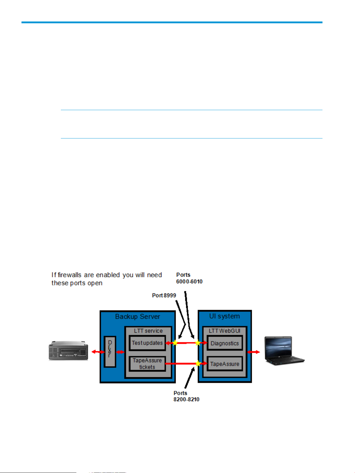
Communication ports
When the LTT Service and Web GUI are installed on different computers the firewall on each
computer needs to be configured to allow communication on the applicable ports as shown in
Figure 2 (page 12).
Figure 2 Ports used for communication between the LTT Service and WebGUI
12 Installing L&TT
Page 13

Ports used on the server running the LTT Service
On the backup server, open:
• 8999 to receive requests from the WebGUI
Ports used on the computer running the WebGUI
On the user interface computer, open:
• 6000 — 6010 to receive test updates from the LTT Service
• 8200 — 8210 to receive TapeAssure tickets from the LTT Service
Installing the LTT Service
The L&TT diagnostic functionality is provided by the LTT Service.
NOTE: If the LTT Service is unable to communicate with the WebGUI or Command View TL, all
tickets are stored locally until communication is established. This can happen if the WebGUI or
Command View TL has not been installed or is not running, or if the LTT Service has not be
configured correctly.
Installation prerequisites
Download link http://www.hp.com/support/tapetools
Install time (typical) 5 minutes
Software dependencies When using Mozilla Firefox, set
dom.allow_scripts_to_close_windows to true. For
instructions, see “Configuring Firefox for use with the WebGUI”
(page 18).
Installation procedure
1. Download or copy the self-extracting executable file to the desktop or another temporary
location.
2. Double-click the self-extracting executable file to launch the installer. The InstallShield Wizard
screen is displayed.
3. Answer yes to all the prompts.
4. Re-boot the server if requested to do so.
5. The installer will offer to open the Windows Firewall ports necessary for the LTT Service to
communicate with the WebGUI, which is necessary when the LTT Service and WebGUI are
running on different servers. This port is specific to L&TT and opening it will not affect the
security of the system.
• Single server — If the LTT Service and WebGUI will always be running on the same
server, you can click No to leave the firewall ports as they are. If you later decide to run
the WebGUI on a different computer you can configure the ports manually.
• Multiple server — If the LTT Service and WebGUI will be running on different servers,
the firewall port 8999 must be open to allow communication between the two components.
To have the installer configure the port automatically, click Yes. If you prefer to configure
the port manually, click No and then follow the instructions in “Configuring firewall ports”
(page 18).
Installing the LTT Service 13
Page 14

6. Optional: Configure the service’s monitoring functionality by modifying the config\
sta_service.cfg file in the installation directory.
NOTE: In L&TT 5.1 the addresses of the WebGUIs are automatically configured during
registration and are available in the config\RegisteredUsers.txt file in the installation
directory.
a. In environments containing both tape libraries and standalone tape drives, use the
Command View TL management station to manage the standalone drives and library
drives. In this case, configure the MANAGEMENT_STATION_IP with the IP address for
the server that will host the Command View TL management station for TapeAssure
monitoring.
b. Set any other specific parameters, such as the rate at which tickets will be pulled. The
default settings are recommended in most cases. To configure additional parameters, see
“Setting service configurations” (page 14).
Most changes to the configuration will be detected automatically within five minutes. The
service can always be re-started to detect all configurations.
See “Setting service configurations” (page 14) for more detailed information on the available
parameters and which require a restart of the service.
Setting service configurations
You can set up and control the behavior of the LTT Service by changing parameter values in the
configuration file \config\sta_service.cfg in the installation directory.
NOTE: In most cases, the settings can be left at their default values except to specify the IP address
of the system on which Command View TL management station is installed. You can leave the other
settings in their default values.
IMPORTANT: If the drive is part of an automation configuration in which Command View TL is
in use, the management station IP address should be the address of the Command View TL
management station with the MANAGEMENT_STATION_PORT of 8099.
In a standalone-only configuration, the L&TT WebGUI collects the tickets using port 8200.
NOTE: If the value entered is invalid, the LTT Service will continue using the previous valid value.
If there are not previous values, the LTT Service will use the default value.
If the LTT Service detects an invalid value for any of the configuration keys in the configuration file,
the LTT Service will modify the configuration file to restore the values to the previous valid or default
values.
HP LTT Service parameters
• TICKET_STORING_LOCATION
The location where the drive tickets will be stored before being sent to the management station
or WebGUI. Defaults to the logs\tktstorage folder in the HP LTT Service software
installation directory. Changes to this parameter are dynamic and will take effect immediately.
• ELTT_INITALIZATION_LOCATION
The location for eLTT (embedded LTT) working files. Defaults to the eLTT\logs folder in the
HP LTT Service software installation directory. Changes to this parameter will take effect
only when the service is started.
14 Installing L&TT
Page 15

• MAX_TICKET_STORE
The maximum disk space allocated for local ticket storage (in MB) before being sent to the
management station. Defaults to 100 MB, must be at least 10 MB. Changes to this parameter
are dynamic and will take effect immediately.
• MANAGEMENT_STATION_IP
The IP address of the Command View TL management station receiving monitoring data. Can
be an IPv4 or IPv6 address, or domain name. Changes to this parameter are dynamic and
will take effect immediately.
• MANAGEMENT_STATION_PORT
The port number on which the TapeAssure monitoring service is listening. Changes to this
parameter will take effect only when the service is started.
◦ The L&TT WebGUI uses port 8200, the default value. The port used by the WebGUI can
be changed.
◦ Command View TL uses port 8099.
• TICKET_TIMEOUT
The timeout, measured in seconds, for pulling tickets. The default is ten minutes. If any of the
ticket commands take longer than this setting, the system will stop pulling the ticket. Partial
tickets are logged in the LTT Service log file. You must set this parameter to allow for long
commands, such as rewind and unload, to complete.
Changes to this parameter are dynamic and will take effect immediately.
• POLLING_INTERVAL
The number of minutes between pulling tickets. The default is six hours (four tickets per day).
These tickets are in addition to tickets pulled on application unload.
Use this feature when the backup application is not configured to unload the tape at the end
of the backup. The poll interval can be very large because the ticket is only needed at the end
of the job.
Set to zero to turn off timed tickets completely.
Changes to this parameter are dynamic and will take effect immediately.
NOTE: Because of the passive nature of pulling tickets and use of the filter driver, pulling
TapeAssure tickets will not disrupt backup operations. Pulling a ticket may slow the backup
by a few seconds, but at only four tickets per day, this will only occur at most once per backup.
• DRIVES_TO_BE_DISABLED
List of drives for which tickets will not be pulled. Use this configuration setting to selectively
disable monitoring of one or more drives. For multiple drives, separate the drive serial numbers
with a comma. For example:
DRIVES_TO_BE_DISABLED=P200000916, HU10018ADR
Installing the LTT Service 15
Page 16

NOTE: Disabling monitoring through the configuration file will stop the service from pulling
any further support tickets from that drive. However, any pending tickets for that drive to be
sent to the management station.
NOTE: The LTT Service does not pull TapeAssure tickets from drives in libraries; these tickets
are pulled by the libraries themselves. Tickets pulled by libraries must be sent to CommandView
TL rather than to the LTT Service.
• RETAIN_RECENT_TICKETS
Controls whether the recent ticket for each drive is retained or not. Valid values are:
◦ 1 — retains the recent ticket for each drive (default behavior)
◦ 0 — does not retain the recent ticket for each drive
If an invalid value is configured, the previously configured valid value will be used.
TIP: Retaining tickets is extremely useful for diagnostic purposed because they can be sent
to HP support for analysis without the need for further user interaction.
Reporting events to the Windows application log
The LTT Service reports events in the Windows application log for:
• Any errors encountered that affect the operation of the service.
• Configuration changes.
• Management station availability and connectivity related issues.
• Reaching the ticket storage size limitation.
You can control which categories of events are recorded in the application log by editing the
config\sta_event_configuration.cfg file in the installation directory. To disable a
category of events from being reported, set the last field for the event category to 0. For example,
EQ:101:Information:1 <--- to enable event ID 101
EQ:101:Information:0 <--- to disable event ID 101
The categories are listed in the config\Event_list file in the installation directory.
Installing the WebGUI
The Windows version of L&TT uses the InstallShield application for installation. InstallShield sets
up shortcuts to launch the application in the Start menu and on the desktop, and set up other
options. Although InstallShield will let you change the installation directory, HP recommends using
the default location for ease of communication.
Upgrading from L&TT 4.x
L&TT 5.x and L&TT 4.x are installed into different directories by default and can be installed on
the same computer. No specific action is required to upgrade from L&TT 4.x to L&TT 5.x. HP
recommends leaving L&TT 4.x installed on the server for access to functionality not yet available
in L&TT 5.x.
NOTE: While both L&TT 5.x and L&TT 4.x can be installed on a system at the same time, only
one of these applications can discover a library on that system at a time. So, only run either the
L&TT 5.x WebGUI or L&TT 4.x at a time when connecting to a library on the local system.
16 Installing L&TT
Page 17

Upgrading from L&TT 5.0
To upgrade from L&TT 5.0 to L&TT 5.1, follow the installation process. The software will be updated
and all database information, including TapeAssure data, LTT Service registrations, and device
information will be retained.
Installation prerequisites
Download link http://www.hp.com/support/tapetools
Install time (typical) 10 - 15 minutes
Software dependencies The WebGUI requires a web browser with Adobe Flash.
Installation procedure
1. Download or copy the self-extracting executable file to the desktop or another temporary
location.
IMPORTANT: Do not rename this file. Renaming the file might create a conflict that prevents
L&TT from installing.
When using Mozilla Firefox, set
dom.allow_scripts_to_close_windows to true. For
instructions, see “Configuring Firefox for use with the WebGUI”
(page 18).
2. Double-click the self-extracting executable file to launch the installer. The InstallShield Wizard
screen is displayed.
3. Click Next. Read the program license agreement and click Yes if you agree to and accept
the terms of the license agreement.
4. Read the readme file for any last-minute changes to the documentation, then click Next. The
Select Features screen is displayed.
5. Select a destination location to install the program. You can accept the default location or
click Browse to install to a different location. After choosing the destination location, click
Next.
6. On the Ready to start installation process screen, click Next. If you need to review or change
installation settings, click Back.
7. The installer will automatically open free ports in the following ranges in the Windows firewall
settings:
• 6000 - 6009: To communicate with the LTT Service when it is installed on another server.
• 8200 - 8209: To receive TapeAssure device monitoring information
• 6055 - 6064: To run the WebGUI from another computer
If the LTT Service and WebGUI are installed on the same computer and you don’t want to
access the WebGUI from another computer, you can click No.
If you want to have the installer open the ports, click Yes.
If you want to configure the firewall ports manually, follow the instructions in “Configuring
firewall ports” (page 18).
8. When the installation is complete, the InstallShield wizard displays its final screen. Click Finish
to start the WebGUI, or deselect the check box, and click Finish to close the InstallSield wizard
without running L&TT.
Installing the WebGUI 17
Page 18
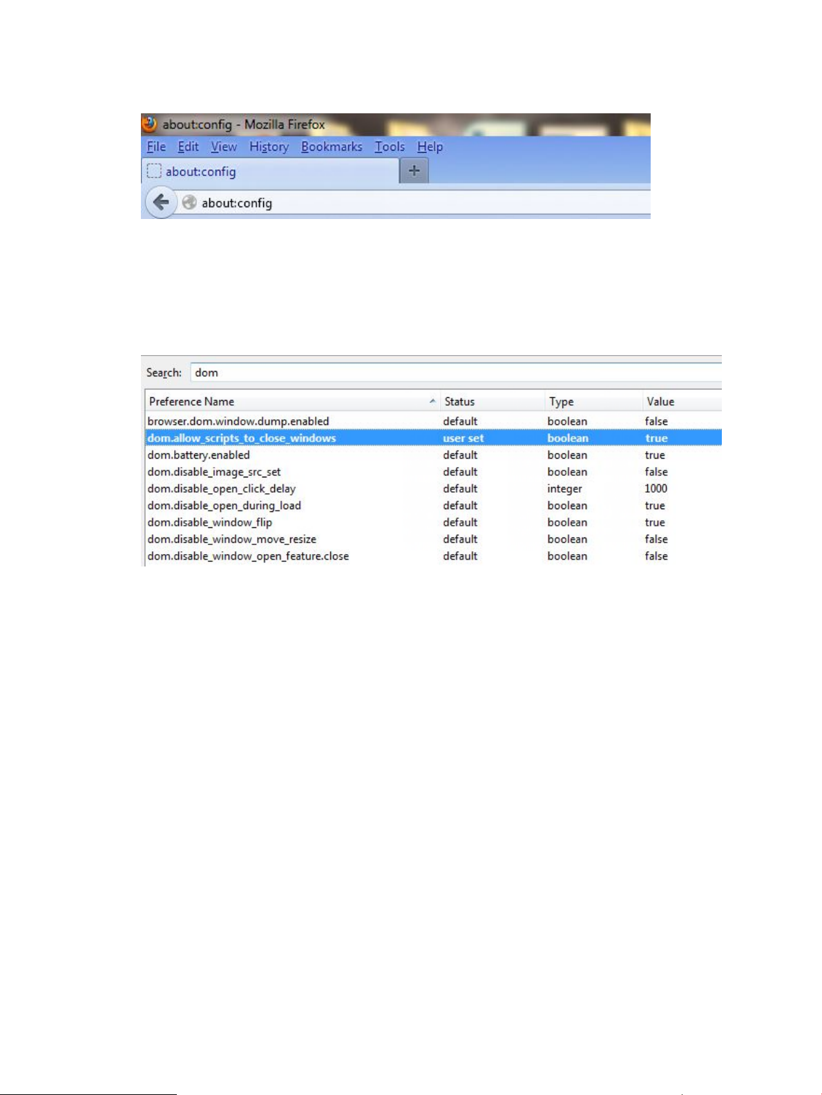
Configuring Firefox for use with the WebGUI
1. Open Mozilla Firefox, type about:config in the address bar, and press Enter.
The browser will display a warning message. Accept the warning.
2. The browser will display a list of settings that can be modified. Type dom in the search field
and press Enter.
3. If dom.allow_scripts_to_close_windows is set to false, double-click it to set the
value to true.
Configuring firewall ports
The installer automatically opens the Windows firewall ports necessary for the WebGUI and LTT
Service to communicate when they are installed on different servers. If you declined to have the
installer configure the ports, follow these instructions to configure the ports manually.
On the server running the LTT Service, open port 8999.
On the server running the WebGUI, open the applicable ports:
• 6000 - 6009: To communicate with the LTT Service
• 8200 - 8209: To receive TapeAssure device monitoring information
• 6055 - 6064: To run the WebGUI from another computer
To open ports on Windows 7:
1. Navigate to the Windows Control Panel.
2. Select System and Security.
3. Select Windows Firewall.
4. Navigate to Advanced settings and then create a new Inbound rule for the port or range of
ports.
18 Installing L&TT
Page 19
3 Using the L&TT WebGUI
Starting the L&TT WebGUI
Start the L&TT WebGUI from the desktop shortcut or from the Windows start menu by selecting
Library and Tape Tools WebGUI. The GUI will start in a new browser window.
Navigating the L&TT WebGUI
Most windows are divided vertically into two panels. The left panel contains a list showing a
hierarchical structure. The right panel displays additional information about items selected in the
left panel.
Some panels show data in columns. To show text that is truncated, drag the vertical lines between
the column titles to adjust the width of the columns or pause your mouse over truncated text to show
the complete text as a tool tip. Depending on the data being displayed, you can find more detailed
information by:
• Double-clicking an item in the list.
• Selecting one or more items in the list, and then selecting an item in the Actions menu.
Most windows have an Actions menu that displays a list of actions that you can perform from that
window or on the selected item. Menu items in bold type show the default action for that window
or selected item. Double-click the item to perform the action.
CAUTION: Use the various tabs, menus, and buttons throughout the program to navigate. Do
not use the browser navigation buttons. Doing so may cause loss of configuration data entered on
a window.
L&TT uses toolbar buttons to perform tasks. These buttons may or may not be available depending
on the window. For the buttons and a description of the action performed, see “Toolbar buttons”
(page 19).
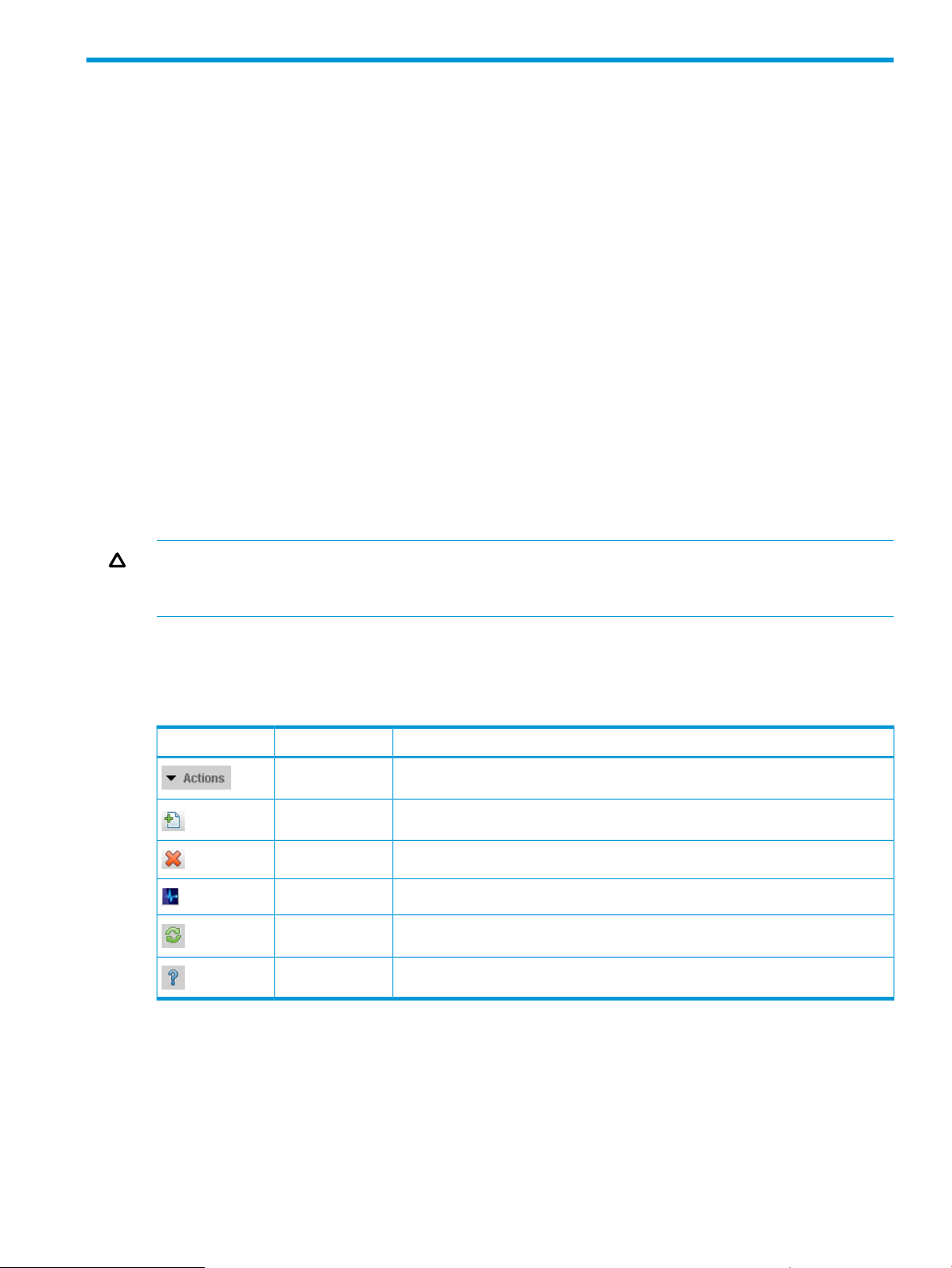
Table 2 Toolbar buttons
DescriptionNameButton
Displays a menu of available actions for the current window or selected items.Actions
Adds LTT Service.Add
Remove the selected item.Delete
Perform diagnostics on the selected item.Run Diagnostics
Refreshes the data on the current window.Refresh
Opens a help topic associated with the current window.Help
Using the All LTT Service Hosts window
When you select Diagnostics from the left toolbar, L&TT displays the All LTT Service Hosts window.
Starting the L&TT WebGUI 19
Page 20
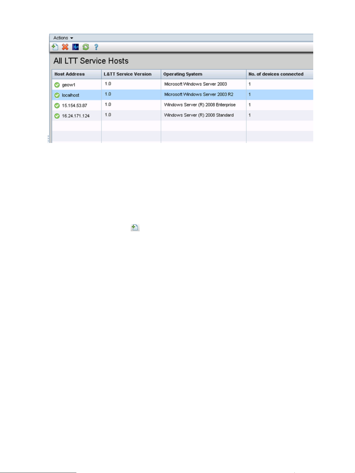
Figure 3 All LTT Service Hosts window
Automatic discovery of service host
When the LTT Service and WebGUI are installed on the same server, the WebGUI will automatically
discover the LTT Service and add a localhost entry. The LTT Service must be installed first for the
WebGUI to discover it, otherwise it will needed to be added.
Adding a service host
You must add a service host for diagnostic access to devices on that host and the LTT Service must
be running on that host. Only add one service host at a time.
1. On the toolbar, click the Add Service button.
2. In the Add L&TT Service Host dialog, enter the address of the server that is running the LTT
Service, and then click OK.
The server address can be entered in any of the standard forms, including
• localhost if the WebGUI and LTT Service are on the same server
• <domain name>.<machine name>
• the machine name if the WebGUI and service host are in the same domain
The GUI registers with the service.
3. Click OK.
4. Repeat the procedure to add another service host.
Removing a service host
1. Select the service host to be removed.
2. In the toolbar, select Actions→Remove L&TT Service or click the Remove button.
3. Click OK.
Removing a service host does not uninstall the LTT Service on that host nor change it in any
way.
Running diagnostics
1. Select the service host associated with the device .
20 Using the L&TT WebGUI
Page 21
2. In the toolbar, double-click the host name in the host list, or select Actions→Run Diagnostics
or click the Run Diagnostics button.
Either a new browser tab or window will display a list of devices attached to the selected
service host, depending on your browser configuration. The WebGUI is easier to use if new
windows open in tabs by default. For instructions on configuring your browser, see the browser
documentation.
Using the LTT Service diagnostics window
The LTT Service diagnostics window displays a list of devices attached to a service host and includes
options to see device information, pull a support ticket, run tests and utilities, and manage firmware.
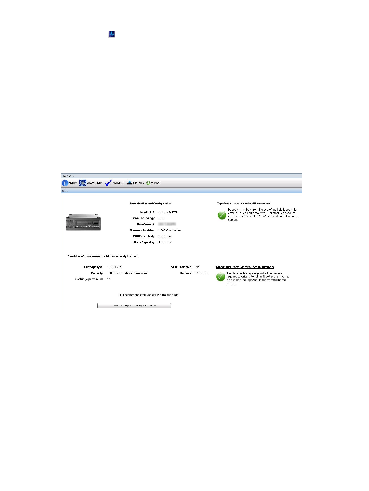
Identification and configuration screen
The identification and configuration screen provides an overview of the selected hardware device
and its current configuration and status. To refresh the screen with the current information from the
LTT Service, click Refresh.
Figure 4 Identification and configuration screen
Identification and configuration information for the device
• Product ID
• Drive Technology — (DLT/SDLT/VS/LTO)
• Drive Serial #
• Firmware Revision
• OBDR Capability — Whether One Button Disaster Recovery is enabled.
• Worm Capability — Whether the drive supports WORM media.
• TapeAssure drive write health summary — Assessment of the drive’s health based on recent
write operations.
Information about the cartridge currently in the drive
• Cartridge type
• Capacity
• Cartridge partitioned — Whether the cartridge has been formatted using LTFS.
Using the LTT Service diagnostics window 21
Page 22
• Write Protected
• Barcode
• TapeAssure cartridge write health summary — Assessment of the cartridge’s health based on
recent write operations.
To see a list of cartridges compatible with the drive, click Drive/Cartridge Compatibility Information.
Using the Support Ticket screen
In the event of a hardware problem, a support ticket can provide vital information to help diagnose
and resolve the problem. Much of the information stored within a device related to operational
characteristics is used by various L&TT tests to analyze the health of the device. However, not all
information can be used in this automated fashion. Some information requires review by qualified
HP personnel to fully diagnose the situation. For this reason, a support ticket should be generated
and e-mailed for further analysis when requested.
For more information about support tickets, see “Using support tickets” (page 74).
To access the Support Ticket screen, select the device you want to generate the support ticket for
in the device list, and then click the Support Ticket icon.
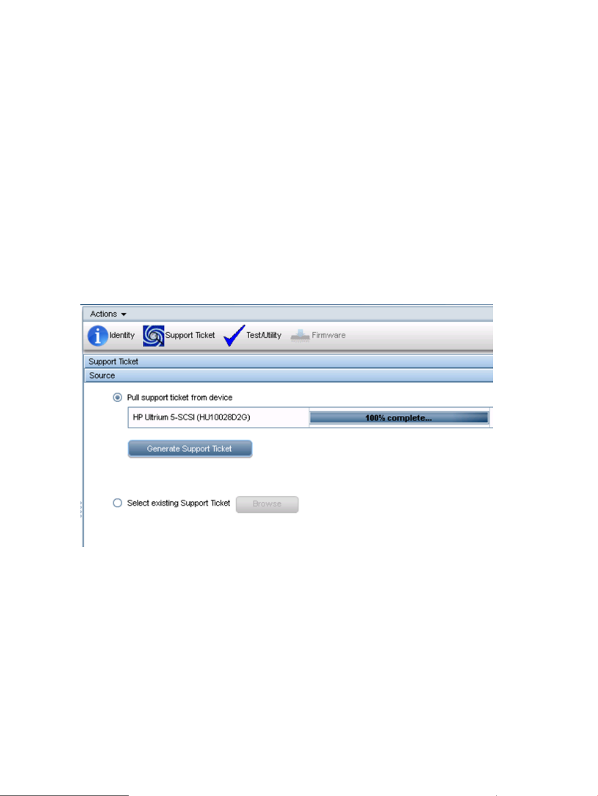
Figure 5 Pulling or selecting a support ticket
To generate a new support ticket:
1. In the Source pane, select Pull support ticket from device.
2. Click Generate Support Ticket.
To view an existing support ticket:
1. In the Source pane, select Select existing Support Ticket and then click Browse.
2. Select a support ticket and click View.
To save a newly generated support ticket:
1. In the Action pane, select Save as.
2. Navigate to the location on the local filesystem where you would like the support ticket saved.
22 Using the L&TT WebGUI
Page 23
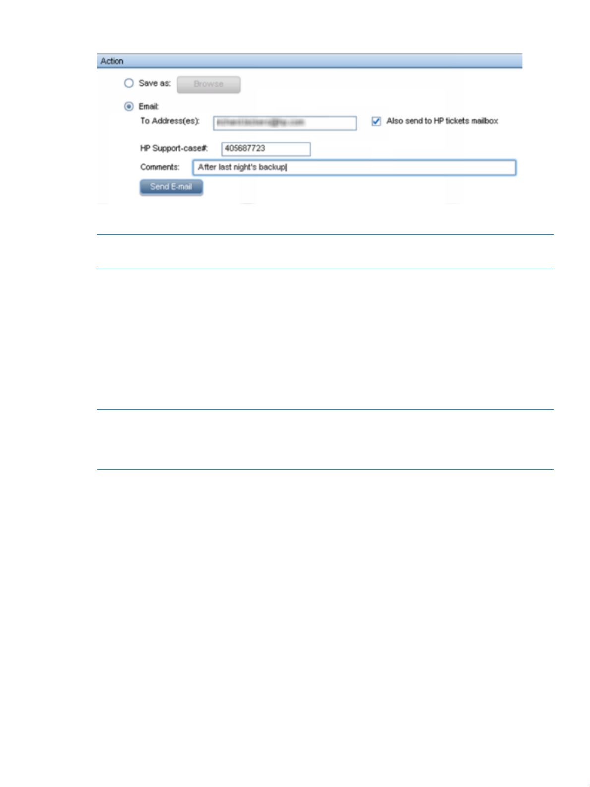
Figure 6 Sending a support ticket by e-mail
To send the support ticket via e-mail:
NOTE: The e-mail server must be configured before support tickets can be sent via e-mail. For
instructions on configuring the e-mail server, see “Configuring the e-mail server” (page 25).
1. In the Action pane, select Email.
2. When sending the support ticket to HP support, enter the support case number and check the
box.
3. Enter the e-mail address.
4. Optionally include comments.
Please allow the WebGUI to copy your tickets to the HP tickets mailbox because this allows
HP support and also the HP development engineers to learn more about how the drives are
performing under real customer conditions. No personal information is contained in the ticket.
5. Click Send E-mail.
NOTE: Support tickets are saved as a zip file that contains both the standard .lzt and .xml form
of the ticket. If you are sending a support ticket to HP support and are unable to use the email
feature of L&TT directly, HP requests that you send the .lzt form of the ticket because it is the most
flexible form.
To view a support ticket generated with L&TT 4.x:
1. In the Source pane, select View lzt or ltd support ticket.
2. Click Upload support ticket.
Using the Test/Utility screen
L&TT provides several tests that can be used to check the performance of, or to diagnose issues
with, storage hardware. To access the Test/Utility screen, click the device you want to test in the
device list and then click Test/Utility on the Action toolbar.
Using the LTT Service diagnostics window 23
Page 24
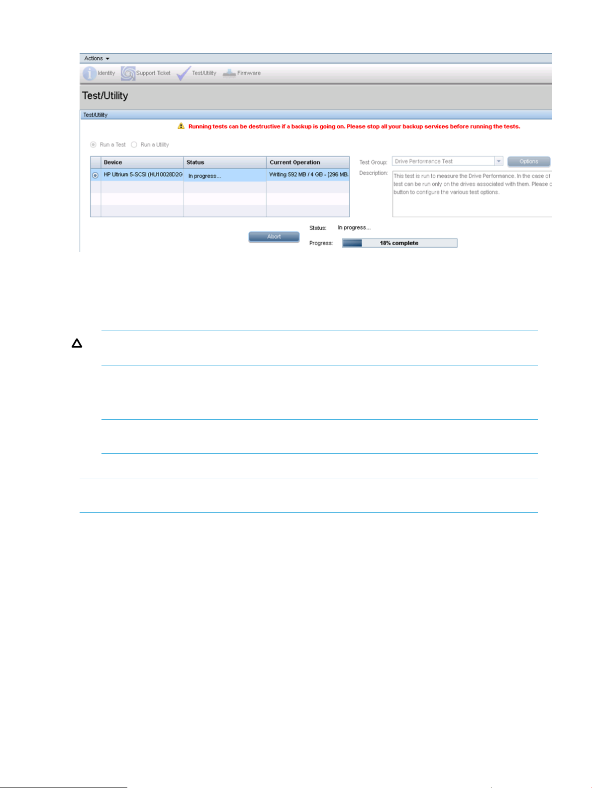
Figure 7 Test/Utility screen
For information about the available tests and utilities, see “Tests and utilities” (page 27).
To run a test or utility:
1. In the Test/Utility pane, select Run a Test or Run a Utility.
2. Select the device.
CAUTION: Running tests can be destructive to data if a backup operation is in progress.
Verify that all backup services are stopped before running tests.
3. Select the test group to run.
4. Click Options and enter any necessary options.
5. Click Start. The test status and progress will be displayed while the test is running.
NOTE: The progress bar is not updated as regularly as it is in L&TT 4.x. This will be improved
in a future release.
To e-mail test results:
NOTE: The e-mail server must be configured before support tickets can be sent via e-mail. For
instructions on configuring the e-mail server, see “Configuring the e-mail server” (page 25).
1. When sending the test results to HP support, enter the support case number and check the
box.
2. Enter the e-mail address.
3. Optionally include comments.
4. Click Send E-mail.
Using the Firmware screen
The firmware management functionality of L&TT allows easy upgrades to storage product firmware.
You must download the firmware for your device from the HP website. To access the Test/Utility
screen, click the device you want to test in the device list and then click Firmware on the Action
toolbar.
24 Using the L&TT WebGUI
Page 25
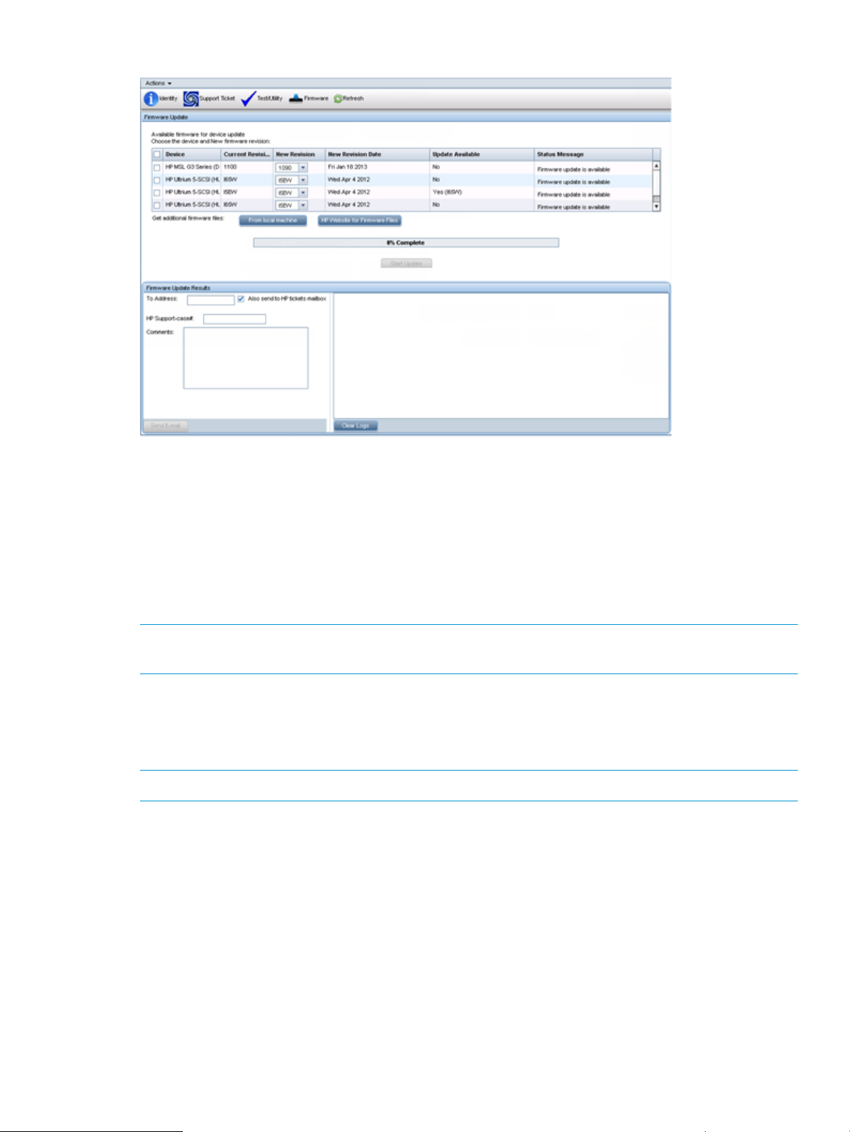
Figure 8 Firmware screen
To update firmware:
1. Download the firmware file for your device from the HP website and place it on your local
computer.
2. In the Firmware pane, check the device.
3. Click From local machine and browse to the location of the downloaded file on your local
computer.
4. Click Start Update.
To e-mail firmware update results:
NOTE: The e-mail server must be configured before support tickets can be sent via e-mail. For
instructions on configuring the e-mail server, see “Configuring the e-mail server” (page 25).
1. When sending results to HP support, enter the support case number and check the box.
2. Enter the e-mail address.
3. Optionally include comments.
4. Click Send E-mail.
NOTE: If multiple drives are selected, the firmware updates will run in parallel.
Configuring the e-mail server
From Email Configuration screen you can configure the e-mail server that L&TT will use to send
outgoing e-mail messages.
Configuring the e-mail server 25
Page 26
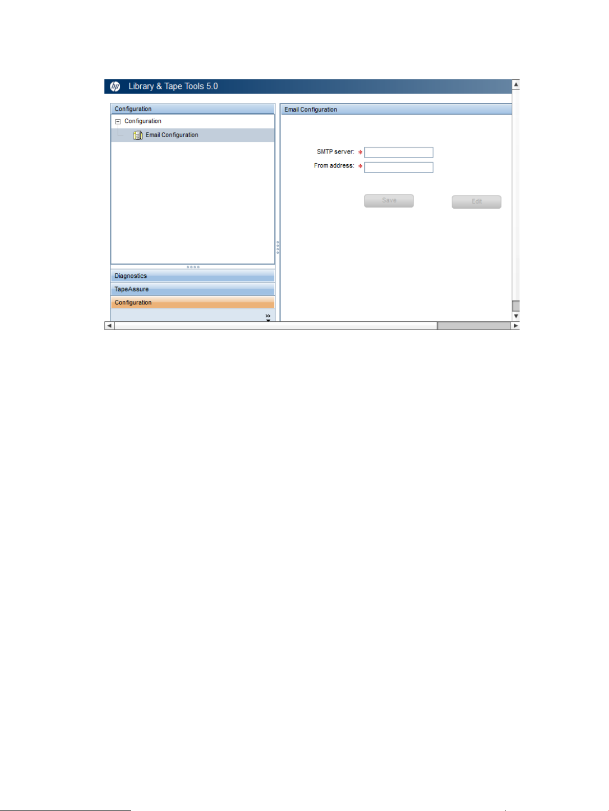
1. On the main screen in the left navigation pane, click Configuration.
The Email Configuration screen appears.
2. Enter the address of the SMTP server.
3. Enter the address for the e-mail message’s reply to field. This address will be displayed as the
“from” address of the e-mail messages from L&TT.
4. Click Save.
26 Using the L&TT WebGUI
Page 27

4 Tests and utilities
Diagnostic tests
CAUTION:
Some tests are destructive to data on the media. When a test is destructive to data, this is indicated
in the test description. To prevent data loss, use media that is either new or that contains unimportant
data that can be erased. Do not attempt to perform a test unless you are thoroughly familiar with
its usage, or have been instructed to do so by HP support personnel.
NOTE: L&TT tests are constantly updated to improve test coverage and problem diagnosis. As
new device issues are discovered, changes are made to the tests to properly diagnose those issues.
Test script updates are distributed with updates to L&TT or with a hot fix distribution. To ensure that
you have the latest available test scripts, keep your version of L&TT up to date when new versions
are made available from www.hp.com/support/TapeTools.
Test results are displayed in the result log in the bottom right-hand corner of the Test/Utilities screen
and are available in the WebGUI install directory, C:\Program Files (x86)\
Hewlett-Packard\Library and Tape Tools WebGUI\log and it’s there under
LTTOperationLog.log. The log file contains all the previous text results and is a text file that
can be viewed in any text editor or sent by e-mail.
“Library Quick Check test” (page 36)
“Library Read Write test” (page 37)“Assessment test” (page 27)
“LTO Cooling Check test” (page 41)“Connectivity test” (page 31)
“LTO Media Assessment test” (page 41)“Data Compression test” (page 31)
“LTO Stuck Tape test” (page 43)“Device Analysis test” (page 32)
“LTO Encryption test” (page 43)“Device Self-Test” (page 33)
“Read/Write test” (page 43)“Library Exercisor test” (page 33)
Assessment test
CAUTION: This test is destructive and will overwrite data on the media that is present in your
product.
For additional information about the LTO drive assessment test, see “About the LTO drive assessment
test” (page 28).
Description The Assessment test determines if the drive or autoloader is Fit for Purpose
(FFP). A device that is determined to be FFP performs according to its
specification. If a device fails the Assessment test, it should be replaced.
If it passes, the problem is likely not with the health of that device. If a
device is returned, the results of this test are compared to repair data
to ensure accuracy and enable test improvements to be developed.
LTO Assessment tests performed:
• Requires that a cartridge be already loaded or in the process of
loading when the test is started.
• Looks at drive history (runs device analysis and looks at LTO reports
information).
• Checks the test cartridge history to insure it is suitable for running
the test.
• Checks whether the drive is requesting cleaning.
Diagnostic tests 27
Page 28

• Performs an unload/load cycle, checking for any mechanical issues
• Writes two wraps of data using varying tape speeds in both
directions measuring write and read-while-write margin
NOTE: If the drive to be tested in part of an autoloader or library, the
autoloader or library should be in random mode prior to running the
test.
Test names LTO Assessment test
Options LTO Assessment test options:
• Allow Overwrite (defaults to FALSE) — set to TRUE to avoid
the interactive warning about erasing data on the test tape
• Test Coverage (defaults to DEFAULT, which is two wraps) — A
wrap is one full length of the tape in one direction. ‘2X' test
coverage is twice the default (4 wraps) and ‘4X' test coverage is
four times the default (8 wraps). Typical test times for
‘Default'/2X/4X test coverage options are 15/30/60 minutes.
Average duration Test times vary greatly depending on drive type, media quality, and
options selected. Average time for a healthy drive with good tape can
range from 10 to 20 minutes. A marginal drive (or drive with marginal
tape) may take substantially longer.
Other notes Requires a good tape that will be overwritten as part of test.
The LTO Assessment test can be stopped before it completes. To abort
the test, click Abort Test.
The test will not run with a tape that has been partitioned.
Available for
• LTO4, LTO5, and LTO6.
About the LTO drive assessment test
The LTO drive assessment test is the most important test in the L&TT diagnostics suite because it is
used to assess the health of a tape drive, providing a clear pass/fail result in about 15 minutes.
If the test reports that the drive is good, the user can be confident that the drive is working as
advertised and is not the cause of any backup or restore issues in the system. If the test fails, HP
support will accept that assessment without further diagnostics, making this a key test for both end
users and HP support.
NOTE: If thereisan issue with the backup or restore process and the assessment test passes the
drive, further diagnostics are needed to find the root cause of the issue elsewhere in the system.
The test contains four main sections:
• Analyze the drive logs. The test pulls over 60 logs from the drives and analyzes them with
about 20 rules and 130 sub-rules. Any issues considered critical in a support ticket, which
uses the same rules, will cause the test to fail the drive at this point. Other issues, such as
cleaning requests or the detection of host polling, will be noted in the test output for
informational purposes.
• Test the load/unload mechanism. The cartridge is unloaded, partially ejected, and reloaded.
Any potential mechanical failures are flagged.
• Run error rate tests. The test runs a series of internal error rate tests at different speeds and
different tape directions. This the core of the assessment test.
• Clean up. The error rate tests leave the cartridge in an 'invalid' state, which is reset with a
short erase process.
28 Tests and utilities
Page 29
Error rate tests
The error rate tests are a series of short tests at a variety of tape speeds in both directions. A typical
test will perform 60–70 individual error rate tests and each one will check error rate margin,
variations across all the heads, and accuracy following tracks. This approach allows for:
• Characterization of drive error rate by tape speed
• Characterization of drive error rate by direction (forward and reverse)
• Filtering out areas of bad tape, which allows the test to run using a single tape
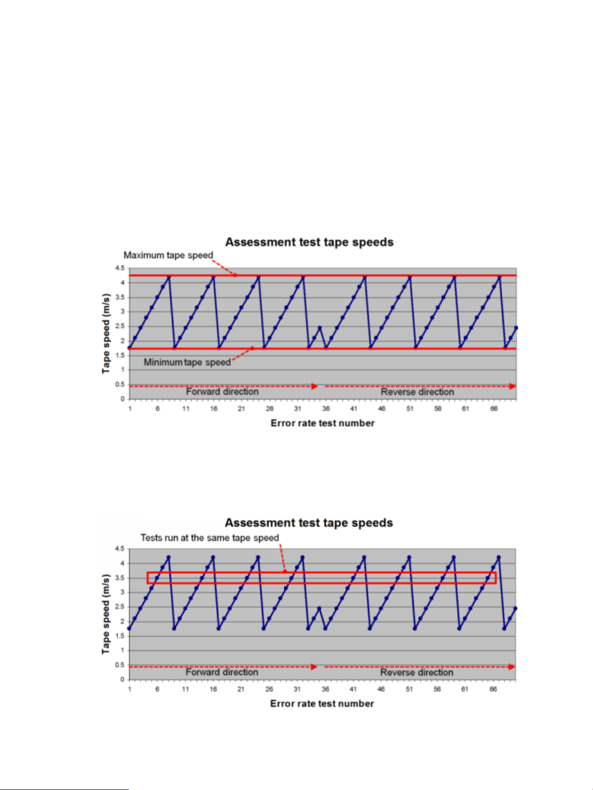
The error rate tests cycle through a series of tape speeds, as shown in “Cycling through a series
of tape speeds” (page 29). Half of the tests are written in the forward direction and the other half
are written in the reverse direction. This ensures that both sets of heads are tested, as well as the
full range of tape speeds.
Figure 9 Cycling through a series of tape speeds
The error rate tests for each tape speed will occur at different places in the tape and in different
directions, as shown in “Multiple tests for each tape speed” (page 29). This allows the test to
characterize the drive for that tape speed.
Figure 10 Multiple tests for each tape speed
Diagnostic tests 29
Page 30
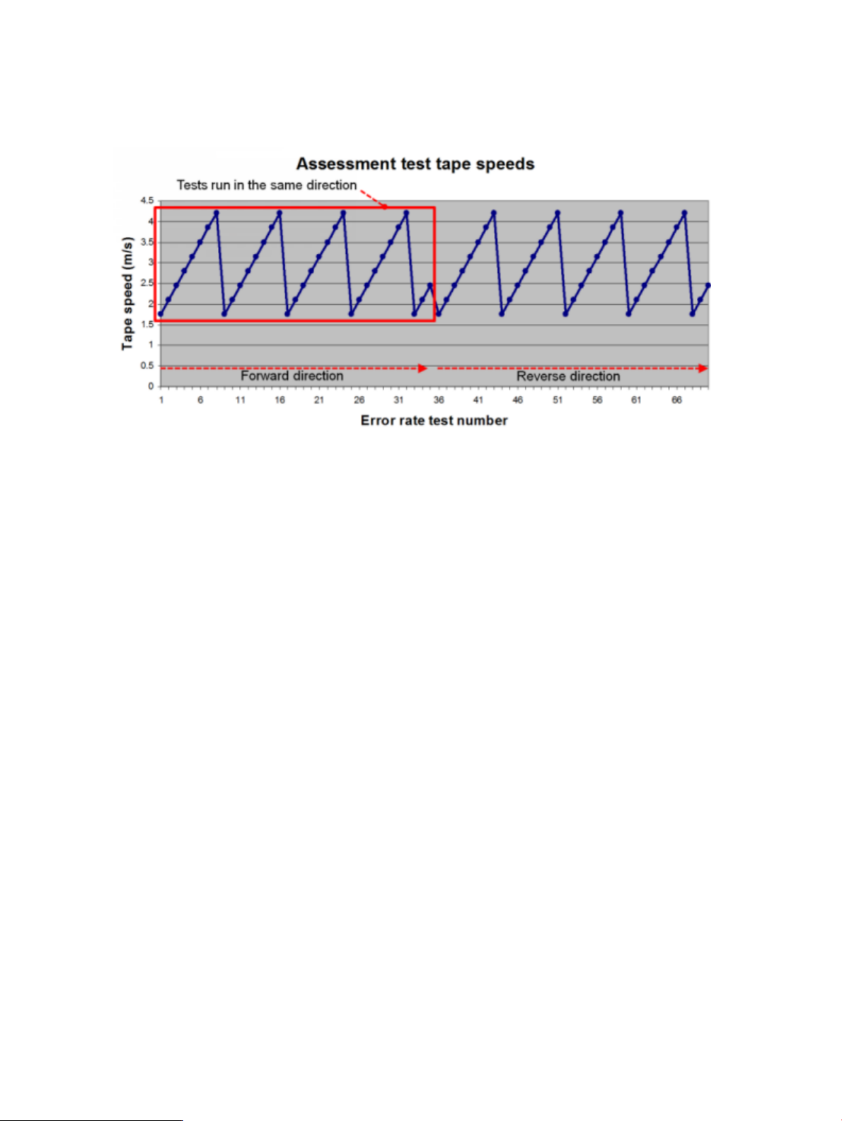
The error rate tests for each direction cover different parts of the tape and are run at different
speeds, as shown in “Multiple tests run in each direction” (page 30). This allows the test to
characterize the drive for each direction, testing each set of heads.
Figure 11 Multiple tests run in each direction
The pass/fail criteria are the same as for the support ticket — the drive must be able to write high
quality data using no more than 20% additional tape to do so. Note that a drive will still work
well even if it needs 50% additional tape but the figure of 20% is used to allow for a little wear
and still leave a great deal of margin.
The output shows the characterization of the drive, first by tape speed and then by direction.
||_ 1.8 m/sec. tape speed:Effective capacity:94.8% Margin: 98.6% (3.0/3.0 GB written using 170.4 meters of
tape)
||_ Channel variation: 0.0% Channel variation margin: 100.0%
||_ Offtrack count: 0 CCQ rewrite percent: 0.1%
||_ 2.1 m/sec. tape speed:Effective capacity:94.8% Margin: 98.4% (3.0/3.0 GB written using 170.5 meters of
tape)
||_ Channel variation: 0.0% Channel variation margin: 100.0%
||_ Offtrack count: 0 CCQ rewrite percent: 0.1%
||_ 2.4 m/sec. tape speed:Effective capacity:94.7% Margin: 98.1% (3.0/3.0 GB written using 170.6 meters of
tape)
||_ Channel variation: 0.0% Channel variation margin: 100.0%
...
...
||_ 3.5 m/sec. tape speed:Effective capacity:94.7% Margin: 98.4% (3.0/3.0 GB written using 128.0 meters of
tape)
||_ Channel variation: 0.0% Channel variation margin: 100.0%
||_ Offtrack count: 0 CCQ rewrite percent: 0.1%
||_ 3.8 m/sec. tape speed:Effective capacity:94.6% Margin: 98.5% (3.0/3.0 GB written using 128.1 meters of
tape)
||_ Channel variation: 0.0% Channel variation margin: 100.0%
||_ Offtrack count: 0 CCQ rewrite percent: 0.1%
||_ 4.2 m/sec. tape speed:Effective capacity:94.6% Margin: 98.4% (3.0/3.0 GB written using 128.1 meters of
tape)
||_ Channel variation: 0.0% Channel variation margin: 100.0%
||_ Offtrack count: 0 CCQ rewrite percent: 0.1%
||_ forward direction:Effective capacity: 95.1% Margin: 100.0% (10.3/10.3 GB written using 594.6 meters of
tape)
||_ Channel variation: 0.0% Channel variation margin: 100.0%
||_ Offtrack count: 0 CCQ rewrite percent: 0.1%
||_ reverse direction:Effective capacity: 94.3% Margin: 96.6% (10.3/10.3 GB written using 599.5 meters of tape)
||_ Channel variation: 0.0% Channel variation margin: 100.0%
||_ Offtrack count: 0 CCQ rewrite percent: 0.1%
||_Overall drive margin:98.3%
||_Worst-case margin (reverse direction):96.6%
Each characterized speed or direction shows:
• Effective capacity — the proportion of tape used that contains the written data. There is a
theoretical possibility of 100%, but some redundancy is to be expected. Anything over 50%
shows a working drive. The pass level is 80%.
• Margin — normalizes the effective capacity to between 0% and 100% such that greater than
0% is a pass and 100% is the realistic maximum.
30 Tests and utilities
Page 31

• Amount of data written compared to the amount attempted.
• Amount of tape used to write the data.
• Channel variation — a percentage comparison across all the heads (16 or 32 depending on
the drive technology)
• Channel variation margin — normalizes the channel variation to between 0% and 100% such
that greater than 0% is acceptable (a pass) and 100% is no variation at all.
• Offtrack count — the number of times the drive had to react to a track following issue. An
offtrack is not an error, but more offtracks will make it harder for the drive to operate within
expected limits.
• CCQ rewrite percent — an internal measure of write redundancy. Another indicator of health.
Anything up to 20% is within limits.
The summary shows a normalized margin figure for the drive overall and also highlights the worst
margin figure from all of the characterizations. This is the key data from the test.
NOTE: The textual output of the test will give the ultimate summary — PASS or FAIL. The test
results can be emailed to HP support for confirmation.
Connectivity test
Description Writes data to the internal buffers in your product to verify that the
Command line syntax Test name: Connectivity Test
physical connection between your host and the storage device is
operational. No media is required.
Options:
• Looping Options— Specify Count based loop or Time
based loop(min). In either case, the actual value is entered
separately using the Looping value parameter.
For example, to set a time-based loop of 10 minutes:
testopt=”Looping Options:Time based loop(min)”
testopt=”Looping value:10”
• Looping value—Specify an integer greater than zero.
For example, to set a count-based loop to iterate five times:
testopt=”Looping Options:Count based loop”
testopt=”Looping value:5”
NOTE: If no options are specified, by default L&TT runs the test
with looping options set to Count based loop with a looping
value of 1.
When to run Run this test when there is a question about the integrity of the bus
connection from the device to the host computer.
Average duration < 1 minute
Other notes Test will not overwrite any data on media present in the drive.
Available for LTO drives, and MSL libraries
Data Compression test
CAUTION: This test is destructive and will overwrite data on the media that is present in your
product.
Diagnostic tests 31
Page 32

Description Tests the hardware compression capability of your tape drive. The test
When to run Run this test when you want to verify that data compression is working
Average duration < 10 minutes
Other notes Test will overwrite all data on the media.
Available for All tape products (drive and automation) supported by L&TT
Device Analysis test
Description The Device Analysis test runs a device-specific script that carries
writes a data pattern of known compressibility to tape. The test then
rewinds the tape and reads the file just written. The read and write
hardware compression ratios are calculated to ascertain that the
hardware compression is working. The compression ratios are displayed
and should be approximately 2:1. Anything less than 2:1 means that
hardware compression is not working. This test is useful if tape capacity
or hardware compression is in doubt.
properly.
out a detailed examination of the device. The test examines all
available logs from the device to look for any known issues,
customer use issues, and common error patterns. The test also
provides summary information and presents suggestions as to the
cause of certain errors and any remedial actions the user should
take. This option is particularly useful if you suspect that there may
be a problem with the device.
The Device Analysis test can be executed manually through the Tests
screen or automatically whenever a support ticket is generated. The
Device Analysis test is unique among all the tests offered by L&TT.
In addition to performing SCSI operations directly on a device, the
Device Analysis test uses a set of predefined, device-specific rules
to analyze device logs and configurations. If any known issues are
discovered during the analysis, the user is notified of the problem
and the program suggests an appropriate course of action.
The Device Analysis test automates failure analysis of a device by
determining
Command line syntax Test name: Device Analysis
When to run Run this test when you want to verify that basic functions of the
Average duration < 1 minute
Other notes Test does not change the configuration of the drive or media.
Available for All devices supported by L&TT
32 Tests and utilities
• whether a known or unknown problem with a device exists
• if the problem can be resolved in the field through maintenance
or simple repair
• whether a device needs to be returned or serviced
Options: None
device are operating properly and have not logged any critical
errors, and to verify that firmware is up to date.
Page 33

Device Self-Test
Description This test executes the internal self-test of the device and reports any
Command line syntax Test name: Device Self Test
failures. This test is useful in confirming that the device itself is
operating properly. Not all devices support an internal self-test.
Options:
• Looping Options—Specify Count based loop or Time
based loop(min). In either case, the actual value is entered
separately using the Looping value parameter.
For example, to set a time-based loop of 10 minutes:
testopt=”Looping Options:Time based loop(min)”
testopt=”Looping value:10”
• Looping value—Specify an integer greater than zero.
For example, to set a count-based loop to iterate five times:
testopt=”Looping Options:Count based loop”
testopt=”Looping value:5”
NOTE: If no options are specified, L&TT runs the test with looping
options set to Count based loop with a looping value of 1.
When to run Run this test as a quick check of the integrity of the device.
Average duration < 1 minute
Other notes Test will not overwrite any data on media present in the drive.
Available for LTO autoloaders and drives, ESL, MSL, C7200, C7145, C5177,
Library Exerciser test
CAUTION: When run on the MSL, ESL, and EML series libraries, this test does NOT overwrite
data. However, on other libraries, this test may overwrite data depending on how the test options
are configured.
Description This is a general-purpose test of the library. The test exercises the library
When to run Run this test to verify that the library is functioning properly.
Average duration Highly dependent on the library being tested and the options selected.
Other notes Depending on the library model and test options selected, this test may
C1194F, C5151, C5173, C6280, SSL 1016 and STK libraries,
STK 9840 drives
robotics by moving media to and from all of the selected elements in
the library. There are two versions of this test, depending on the library
model. For more information, see “Using the Library Exerciser
Test” (page 34).
overwrite data. The test will not overwrite data on MSL, ESL, and EML
series libraries. For more information, see “Using the Library Exerciser
Test” (page 34).
This test can be stopped before it completes. To abort the test, click
Abort Test.
Available for Not all libraries are supported by the Library Exerciser test. If the test is
not displayed in the list of tests, then the selected device is not supported.
Diagnostic tests 33
Page 34

Using the Library Exerciser test
There are two versions of the Library Exerciser test depending on the model of the library or
autoloader being tested. The latest version of the Library Exerciser test is used on the MSL2024,
MSL4048, MSL8048, MSL8096, EML, ESL 9000, and MSL 5000/6000 libraries, and the 1/8
G2 tape autoloader. Other library models use a previous version of the Library Exerciser test (see
“Using the original version” (page 35)).
Using the new version
By default, the new version of the Library Exerciser test verifies that the device robotics can access
every drive, storage, and mail slot element in the library or autoloader by physically performing
media moves to each location. Optionally, a subset of elements can be selected to focus the test
on a specific area of the library or autoloader.
NOTE: This test can take a long time on very large libraries. If a shorter test is desired, use the
test options to select a subset of elements to test.
The test requires at least one piece of media in the storage and mail slot elements that are selected
for test. By default, the test attempts to verify media compatibility, so if multiple tape technologies
or generations are present in the library, one cartridge of each applicable type should be present.
The MSL2024 and MSL4048 libraries, and 1/8 G2 tape autoloader also require at least one
empty element in the selected storage and mail slot range.
The following options are available for this test:
• Perform inventory at start of test— By default, this option is set to False because
the inventory operation can take a long time on large libraries. If the inventory information
needs to be updated, setting this option to True causes an Initialize Element Status
command to be issued to the library at the start of the test.
• Test loop count (all operations except inventory)— Allows multiple loops of the test to
be run. The inventory operation (if selected) only runs prior to the first loop. The default value
is 1.
• Test drive range (all, x-y, or none)— Specify the range of drives to be tested. Specify
all to test all drive elements. Specify none to skip all drive elements. Specify a single number
(5, for example) or a range (2-5, for example) to test specific drive elements (numbering starts
at 1).
• Test Import/Export range (all, x-y, or none)— Specify the range of import/export
(mail slot) elements to be tested. Specify all to test all import/export elements. Specify none
to skip all import/export elements. Specify a single number (5, for example) or a range (2-5,
for example) to test specific import/export elements (numbering starts at 1).
• Test slot range (all, x-y, or none)— Specify the range of slot (storage) elements to be
tested. Specify all to test all storage elements. Specify none to skip all storage elements. Specify
a single number (5, for example) or a range (2-5, for example) to test specific storage elements
(numbering starts at 1).
• Ignore barcode labels and media types when selecting tapes— To ensure
that attempted moves are made only to elements that are compatible with the selected media,
the test attempts to use bar code label and/or Read Element Status information from the library
to determine media types by default. If bar code labels are missing or incorrect, it may be
necessary for this option to be set to True to allow the test to run. This option should only be
set to True if all of the media in the selected range is compatible with all of the elements in
the selected range. If this option is set to True and more than one drive type is detected in the
selected range, the test will exit without moving media. The range options can be used to
select ranges of elements that are known to be compatible.
34 Tests and utilities
Page 35

Using the original version
The Library Exerciser test takes a test cartridge from a mail slot and performs random slot-to-slot
moves. The test then moves the test cartridge into every available drive and performs a short drive
test. This test is intended to exercise the robotics and robot drive hardware.
NOTE: Not all libraries are supported by the Library Exerciser test. If the test is not displayed in
the list of tests, then the selected device is not supported.
The following options are available for this test:
• Test Time Limit— Specify the time limit in minutes. Enter 0 for no time limit. The default
setting is 0.
• Move Command Timeout— Specify the maximum time allotted, in seconds, for each move
command before failure. The default is 600 seconds.
• Active Slot Range— Specify a range of slots to be tested. Enter a range of slot numbers
separated with a dash (for example: 2-5), or enter all to specify all slots. The default is all.
• Active Drive Range— Specify a range of drives to be tested. Enter a range of drives
separated with a dash (for example: 2-5), or enter all to specify all drives. The default is all.
• Drive Type Option— Specify the type of drives to be tested (in libraries that have mixed
drive types). Enter the type of drive (for example: LTO or DLT), or enter all to test all drive
types. The default is all.
• Check Inventory Mode— Specify whether to perform an active inventory check at
beginning of the test. The active inventory check can take a long time to perform. The default
is on.
• Barcode Mode— Specify how bar codes are handled. Choose one of the following options:
Show all— Shows all bar codes◦
◦ Show suspect— Shows only suspect bar codes (default)
◦ Off— Does not show bar codes
• Slot-to-Slot Moves— Select one of the following options for the slot-to-slot test:
All— Moves all cartridges◦
◦ Random— Moves randomly selected cartridges (default)
◦ Off— No cartridges are moved
• Random Coverage— When Slot-to-Slot Moves is set to Random, specify the percentage of
units covered during random test. The default is 20%.
• Drive Load Mode— Specify whether or not to perform the Drive Load test. The default
setting is on.
• Drive Test Option— If the Drive Load test is enabled, specify one of the following options:
Off◦
◦ Data loop back (default)
◦ Read-only
◦ Read/write
Diagnostic tests 35
Page 36

• Cartridge Load Test— Specify one of the following options for the Cartridge Load test:
Off (default)◦
◦ Single drive
◦ Multiple drives
◦ All drives
• CM Integrity Mode—Specify whether to enable the CM integrity check option for LTO
drives. The default setting is on.
Library Quick Check test
Description The Library Quick Check test performs a quick check of both the library
and installed tape drives for both VLS/D2D and real libraries. The test
checks the library move functionality and checks the read, write, and
load functions of each tape drive installed in the library.
The test starts by moving any tapes currently loaded in the tape drives
back to their source slots. If source information is not available for any
tapes loaded in drives, the test will exit with a warning and test status
Incomplete. After moving any currently loaded tapes back to their
source slots, there must be at least one empty slot or the test will skip
the slot-to-slot move portion of the test.
The test identifies test tapes and the empty test slot based on the types
of tape drives installed in the library and the value of the Starting slot
option. For example, if the library has a mixture of LTO2 and LTO4 tape
drives and the value of the Starting slot option is 10, the test will identify
the first LTO2 tape and the first LTO4 tape starting with slot 10, and
these will be come the test tapes for that test run. There is one tape per
drive type. For example if the library has multiple LTO2 tape drives and
multiple LTO4 tape drives, the test will use two test tapes — one for the
LTO2 tape drives and one for the LTO4 tape drives. In this example, the
empty test slot will be the first empty slot found starting with slot 10.
The test exits with a warning and test status of Incomplete in any of
the following conditions:
36 Tests and utilities
• The test cannot find a test tape for each drive type
• Any of the identified test tapes are write protected
• The test cannot find an empty slot.
The test fails in any of the following conditions:
• The library has any move errors, including any initial moves to
return a tape to its source slot.
• A tape drive has any write or read unexpected check conditions,
or the data read is different from the data written.
Page 37

Options
Allow overwrite (default FALSE) — This test option must be set
•
to True before the test will run.
• Starting slot for locating test tapes (default 0) —
The test looks for test tapes starting with the specified slot. If the end
of the slot range is reached before finding the required test tapes,
the test continues looking from slot 0, stopping the search when the
starting slot is reached.
• Additional moves (default 0) — By default, the test moves the
first identified test tape to the first identified empty slot and back
two times. Use this option to increase the number of slot-to-slot move
sequences.
• Additional seconds writing (default 0) — The test writes
for a minimum of 30 seconds with each drive in the library and
then reads back the test data written during that time. Use this option
to increase the writing time.
• Ignore barcode labels when selecting test tapes
(default FALSE) — By default, the test uses barcode information to
select a test tape for each drive in the library. Use this option to
have the test treat each tape in the library as a valid tape type for
each drive in the library. When set to True, the test will use the first
tape found from the starting slot ( Starting slot for locating test tapes
option) to test all drives in the library, regardless of the drive type.
This option should only be set to True if the test tape in the starting
slot is compatible with all of the tape drives in the library.
When to run Run this test to check the main library and drive functions.
Average duration Highly dependent on the library being tested.
Other notes This test will overwrite data on the test cartridges.
Available for Both virtual and real library devices, including ESL9000,
Library Read Write test
Description The Library Read Write test automates the testing of the drives and tapes
MSL5000/6000, ESL-E, EML-E, MSL2024, MSL4048, MSL6480,
MSL8048, MSL8096 Tape Libraries, and 1/8 G2 Tape Autoloader.
in a tape library. This test assumes that the library robotics are working
properly. To test the library robotics, use the “Library Exercisor
test” (page 33).
Diagnostic tests 37
Page 38

Options
Allow overwrite (default: FALSE) — Set to TRUE to enable test
•
options which write to the tape. Specifically, if MB to write is
greater than 0 or Run LTO drive assessment test is TRUE,
the test will only run if Allow overwrite is also true.
• Starting slot (defaults to 1) — Specifies the number of the slot
where the test will start checking for compatible tapes.
NOTE: Slot and drive numbering is one-based (the first slot is 1),
which is consistent with L&TT. Some supported libraries use
zero-based numbering on the library front panel. In this case, the
test numbering will be off by one from the front panel.
• Number of test tapes (default: 1) — Specifies the maximum
number of test tapes to be written during the test. If tapes will be
written (see Allow overwrite), the number of test tapes is limited
to the maximum of the number of drives selected with Drive type
and Drive range, or 10 tapes, whichever number is larger. For
example, if six drives are selected in a 32-drive library and the test
is configured to write tapes, then the test will limit the number of
test tapes to 10. If there are 16 drives in the chosen library, the test
will limit the number of test tapes to 16.
If all is selected, the test tapes will be selected from the Starting
slot to the end of the library slot range. If tapes will not be written,
the maximum does not apply.
• Drive range (default: all) — Specifies the range of tape drives
to be considered for the test. Drive numbering starts at one. This
range of drives is checked against the specified Drive type to
determine which drives will be used. For example, 1–3 selects
drives 1, 2 and 3, 2 selects drive 2, and all selects all drives in
the library.
• Drive type (default: same as drive 1) — Specifies the types of
drives to include in the test. The test will exit if the library does not
a drive of the selected type.
• MB to write (default: 0) — Specifies the amount of data to write
to each tape using a random data pattern, 64K block size, and
data compression enabled. If all is specified, the tape will be fully
written to EOM (end of media) and the locations for early warning
EOM and EOM will be published in the test results. These locations
are published as both a block number and a capacity point.
• Run LTO drive assessment test (default FALSE) — Set to
TRUE to run the assessment test. The Enable passive test,
Ignore cleaning request, and Test coverage options
configure the LTO drive assessment portion of the Library Read
Write test.
◦ Enable passive test (default: TRUE) — Specifies whether
device analysis will be run from within the drive assessment
test.
38 Tests and utilities
◦ Ignore cleaning request (default: FALSE) — Specifies
whether cleaning requests will be checked and used as part
of the test criteria.
Test coverage (default: Default) — Specifies how much of
Page 39

the test tape will be written during the assessment test. The
◦
choices are Default and Entire tape.
NOTE: If Run LTO drive assessment test is TRUE and
Drive type is not LTO, the test will exit.
• Continue on drive errors (default: TRUE) — Specifies
whether the test should continue when an unexpected drive error
occurs. This check does not include some expected drive errors,
such as when a drive reaches EOD before reading the specified
amount of data.
NOTE: Robotics errors will always cause the test to fail
immediately.
• Test all drive/tape combinations (default: FALSE) —
Determines which tape/drive combinations to test. For example,
with four selected drives and four selected tapes, if Test all
drive/tape combinations is FALSE, four tape/drive
combinations will be tested, but if Test all drive/tape
combinations is TRUE, 16 tape/drive combinations will be tested.
If Number of test tapes is set to 1, the test will use all
tape/drive combinations, regardless of how the Test all
drive/tape combinations test option is set so that each of
the selected tape drives will be tested.
• Number of iterations (default: 1) — Specifies the number of
times the test sequence will be repeated for each tape/drive
combination.
• Ignore barcode labels (default: FALSE) — Specifies whether
the test should use barcode labels to determine which tapes are
compatible with a tape drive.
• Skip previously inventoried tapes (default FALSE) —
Specifies whether previously inventoried tapes will be skipped when
the test selects the tapes to use for the test run. The information about
previously inventoried tapes is kept in the log file.
When to run Run this test to verify that the tapes and drives are functioning properly.
Average duration Highly dependent on the library being tested and the options selected.
Other notes Depending on the library model and test options selected, this test may
overwrite data.
This test can be stopped before it completes. To stop the test, click Abort
Test.
The test keeps a log file that lists of all tapes in the library that have bar
code labels.
The test will not run with a tape that has been partitioned.
The Library Read Write test has several requirements, some of which
can be overridden with test options:
• Library robotics are working. The test assumes that the library
robotics are working well enough to move tapes, read barcode
Diagnostic tests 39
Page 40

labels, and keep correct inventory. The test will fail immediately
upon the first robotics error.
• No tapes in the selected drives. If there are tapes in any of the
selected drives, the test will move the tapes back to their source
slots at the beginning of the test. A working library should know
the source slots for each tape, as long as the library has not been
rebooted or power-cycled since the tape was loaded into the drive.
If the source slot information is not available in the library, the test
will exit with an error message requesting that the user use the front
panel to replace the tapes in their storage slots.
• Bar code labels are correct. The test uses the bar code labels to
determine whether a tape may be used in a specific drive. The sixth
and seventh characters in the bar code label designate the type of
tape. In addition, cleaning tape bar code labels start with “CLN”,
which is used to exclude any cleaning tapes from the test. The test
chooses which tapes to include based on the bar code labels of
the tapes in the library, along with the option settings for Drive
type, Starting slot, and Number of test tapes.
The requirement for correct bar code labels may be overridden by
setting the [Ignore barcode labels] test option to TRUE.
NOTE: The test will not run with the Ignore barcode labels
test option set to TRUE if the library has mixed drive types because
when the library contains mixed drive types it is more likely that
some of the tapes in the library are not compatible with the chosen
drive type.
• Library is configured to show at least seven bar code characters.
The library must show at least seven bar code characters for the
test to check the bar code labels. The number of bar code characters
shown is a configuration setting that differs between libraries. If the
library is set to show fewer characters, the test will behave as though
none of the tapes in the library are compatible with the chosen tape
drive.
The Library Read Write test keeps a log file containing a list of all tapes
in the library that were identified during previous test runs. This
information is used within the test if the Skip previously
inventoried tapes test option is set. The log files are named
LTTRootDirectory\logs\ProductID_ProductSN_librw.csv.
The list has one entry for each tape, and each entry includes the bar
code, slot, and media ID for SDLT tapes or cartridge SN for LTO tapes.
The bar code and slot information will always be present; the media ID
or cartridge SN will only be present if the tape was loaded during any
run of the Library Read Write test. The log file may be viewed in Excel.
When the Library Read Write test runs, the media ID or cartridge SN
from the log file is combined with any new media information from that
run. The log file is then updated to reflect the new media ID or cartridge
SN information, as well as the current library configuration of tape
locations. If the Library Read Write test is run after a tape is removed
from the library, the information about that tape is discarded from the
log file.
40 Tests and utilities
Page 41

Available for MSL5000/6000, ESL9000, ESL-E, EML, MSL2024, MSL4048,
LTO Cooling Check test
Description This test monitors the temperature sensors of an LTO drive while writing data to
When to run Run this test if you suspect thermal problems with your LTO drive.
Other notes This test can be stopped before it completes. To stop the test, click Abort Test.
TIP: To keep log information about a tape that has been discarded
from the library, copy or rename the log file before running the Library
Read Write test.
The test determines which tapes to use based on the test option settings
for Starting slot, Number of test tapes, Drive type,
Ignore barcode labels, and whether or not the tapes will be
written (see Allow overwrite). For example, LTO1 tapes will not be
included in an LTO3 drive test where tapes are written because LTO1
tape is not write-compatible with LTO3 drives.
The test determines which drives to use based on the test option settings
for Drive type and Drive range.
The other test options determine the testing sequence for the selected
tapes and drives. This testing sequence is always the same for each of
the selected drives and tapes.
MSL6480, MSL8048, MSL8096, and Tape Libraries, and 1/8 G2 Tape
Autoloader. Within these libraries, the following drive types are
supported: SDLT220/320/600, and LTO1, LTO2, LTO3, and LTO4.
ensure that the drive is cooling properly when installed in a server.
LTO Media Assessment test
CAUTION: This test is destructive (if the Allow Overwrite test option is True) and will overwrite
data on the media that is present in your device.
Description The LTO Media Assessment test evaluates two aspects of the LTO media
— the data stored on the media and the tape cartridge itself. The default
is to perform a Read Only test, which analyzes the backup currently on
the LTO data cartridge to check whether the backup is fit for purpose
(FFP). The other test type is an Overwrite test, which overwrites the
existing data on the LTO data cartridge. The Overwrite test ensures that
the media can be successfully written to, which will check whether the
Media is FFP.
If the Read Only (Backup Assessment) test fails, the backup needs to be
run again, but you should run the Overwrite test first to check that the
media is suitable to continue using for Backup operations.
If the Overwrite (Media Assessment) test fails, the media should be retired
and no longer used for Backup operations (i.e. it is no longer FFP). The
test makes no attempt to determine the reason for the problem with the
media; it is intended only to determine whether it is FFP.
The test also does a passive analysis of the tape history. In this part of
the test, the LTO Cartridge Memory is analyzed looking for signs of
health and usage problems. The historical information-based status of
the tape is reported at the end of the test.
Diagnostic tests 41
Page 42

Options HP recommends using the default options, which will perform a Read
Only (Backup Assessment) test and attempt to read two wraps of data
from the tape. Use the Allow Overwrite and Amount of Media
to Test options to modify the default behavior of the test.
• Allow Overwrite (default False) — To run the Read Only
(Backup Assessment) test, set the Allow Overwrite option to
False, or leave it unset. To run the Overwrite (Media Assessment)
test, set the Allow Overwrite option to True.
• Amount of Media to Test — The actual amount of data read
varies by LTO drive/tape generation, but is enough for a valid
Read Margin calculation to be performed. Unless EOD (End of
Data) is reached during the read of the default amount of data, the
test will be unable to report that the Backup is FFP, but it will be a
very good indication of the health of the backup. To fully test the
Backup fitness, set the Amount of Media to Test option to
Entire Tape, which will ensure that the data is read from the tape
until EOD is reached.
The other test options allow the test to be run outside of the standard
operation parameters, which is not recommended:
• Enable passive test (default True) — When this option is set
to True, the passive stage of the test is run. When this option is set
to False, the passive stage of the test is not run. There is not benefit
to disabling the passive stage of the test because it runs very quickly
and gives useful feedback on the history of the tape.
• Check WORM integrity (default True) — When this option is
set to True, the Read Only test is run on a WORM cartridge, which
will check the integrity of the WORM media and that the WORM
cartridge has not been tampered with. This test does not allow
writing to a WORM cartridge.
• Ignore cleaning requests(default False) — If the tape drive
to be tested is requesting cleaning, the drive should be cleaned
before running the test. However, if a cleaning cartridge is not
available, you can bypass this check by setting this option to True.
In that case, the test will report that non-standard test options were
used so the results of the test cannot be guaranteed.
When to run Run this test with the Allow Overwrite option set to True when you want
to check whether a backup is fit for purpose. Run this test with the Allow
Overwrite option set to False when you want to check that a tape
cartridge is fit for purpose.
Average duration Approximately 20 minutes using the default test options, depending on
the drive type.
Other notes Test will overwrite all data on the media if the Allow Overwrite option
is True.
If the drive to be tested in part of an autoloader or library, the autoloader
or library should be in random mode prior to running the test.
The test will not run with a tape that has been partitioned.
Available for LTO drives only
42 Tests and utilities
Page 43

LTO Stuck Tape test
Description This test tries to determine if the cartridge in the drive is physically stuck, or
When to run Run this test only if you suspect that the cartridge is stuck.
Available for Standalone LTO drives only
LTO Encryption test
Description This test checks that the encryption capabilities of the LTO4 or later
When to run Run this test if you want to insure that encryption is working correctly for
Average duration 2–3 minutes
Other notes This test will overwrite all data on the media.
Available for LTO4 and later generation tape drives, both standalone and within
if it can be unloaded and recovered.
generation drive is working correctly. Data is written and read using
different combinations of encryption mode, decryption mode, and using
both invalid and valid keys, checking for the correct response from the
drive in each case. The tape is checked at the beginning of the test to
insure that it will correctly support encryption and may therefore be used
as a test tape.
the LTO4 or later generation drive.
libraries.
Read/Write test
CAUTION: This test is destructive and will overwrite data on the media that is present in your
product.
NOTE: The Read/Write test is superseded by the “Assessment test” (page 27), which asses drive
health, and the “Drive Performance test” (page 45), which measures performance and pushes the
drive to maximum performance. HP recommends using these tests instead of the Read/Write test
because they are effective diagnostics.
Description This test performs a self-test on the drive device, then a write-read media
test to verify the ability to read and write data to and from the removable
media in your storage device. This test also checks error rates and fails
if allowable limits are exceeded. Test options allow the user to select
the amount of data or length of test time, the amount of data transferred
per command, and the data pattern.
The Write/Read test includes the same parameters as the existing Device
Performance test but it should not be used for performance measurements
as it does not use the tape driver and runs more slowly. Please use the
Device Performance test for accurate performance measurements.
Diagnostic tests 43
Page 44

Options
Test Time Limit — Specify the time limit in minutes. Enter 0
•
for no time limit.
• Data Limit Type — Specify one of the following options to limit
the amount of data written/read in each phase:
◦ Time — Limits the amount of data tested based on the time
specified in Data Time Limit.
◦ Size — Limits the amount of data tested based on the size
specified in Data Size Limit.
◦ Whole tape — Limits the amount of data tested based on
the size of the tape.
• Data Size Limit — Specify the size limit in megabytes of data
to be written/read in each phase.
• Data Time Limit — Specify the time limit, in minutes, for each
phase of the test.
• Block Size — Specify the block size, in kilobytes, to be used in
the test. The default is 64 KB.
• Transfer Size Limit — Specify the maximum data transfer
limit, in kilobytes, per command. The default is 64 KB.
• Block Transfer Type — Specify whether to use a fixed or
variable block length.
• Read and compare after the write operation — Set
this option to true to enable the read phase after the write phase
completes. This option is optional and is set to false by default.
The read phase also compares the buffers written during the write
operation to ensure data integrity on the tape.
• Retry on read failure — When on, the test will prompt the
user for a cleaning cartridge and a new test cartridge in the case
of repeated read failures.
• Compression Ratio — Specify the compression ratio for the
test. The test will use a buffer pattern in a pre-specified format to
achieve the specified compression ratio.
• Write filemarks after every — Specify whether the test
should write a filemark on the tape after every specified amount of
data.
When to run Run this test to verify the integrity of a particular piece of media, as
written and read by a particular drive, and to verify the ability of the
drive to read and write data independent of the storage application.
Average duration < 10 minutes, using default test options
Other notes Test will overwrite all data on the media.
This test can be stopped before it completes. To abort the test, click
Abort Test.
Available for All devices supported by L&TT
Performance tests
• The Drive Performance Test writes data to a tape drive and calculates the performance of that
drive independently from the disk file system. Use this test in conjunction with the System
44 Tests and utilities
Page 45

Performance Test to identify any system bottlenecks. Use a blank tape when performing this
test because this test is destructive to data on the tape. The test can also measure tape drive
read performance. This test is available for all tape drives. For more information, see “Drive
Performance test” (page 45).
• The System Performance Test measures the performance of the system on which the LTT Service
is running. It has two modes: The Read Performance Test measures the read performance of
the disk file system (simulating a backup), and the Write Performance Test measures the write
performance of the disk file system (simulating a restore). Use these tests in conjunction with
the Drive Performance Test to identify any system bottlenecks.
The Read Performance Test is read-only and is safe to run on any part of your file system. The
Write Performance Test creates data in the specified directory and can also be used to create
test data for general backup testing. For more information, see “System Performance
test” (page 47).
Drive Performance test
The Drive Performance test writes and reads data to/from the specified tape drive and calculates
performance data for that drive. The results of the test are shown in updates while the test is running
and in the test results section in the bottom right of the Test/Utility screen.
CAUTION: This test is destructive to data on the tape. To avoid loss of data, use a blank tape
when performing this test.
NOTE: In the following procedure, a suggested starting value is given for most parameters. These
are not necessarily default values, but they are general values that will result in a simple,
representative test. Use them as a starting point, and modify them according to your needs.
NOTE: The Drive Performance test uses the tape driver rather than the NT Miniport (or ASPI) to
model the backup application, so the appropriate tape driver must be loaded for this test. To
download the latest driver, go to http://www.hp.com and click Download drivers and software.
1. In the device listing (the By Product or By Connection tab), select the library or drive to test.
2. Click Dev Perf on the main toolbar. The Drive Performance screen opens with the Tape Drive
Performance tab selected. For libraries, the Drive Performance Test tab shows the library and
its associated drives. For a stand alone drive, only a single drive will be shown.
3. Select the tape drives for the Drive Performance test. All of the drives will be tested in parallel.
NOTE: You cannot select the library because the test only runs on tape drives.
4. Click the Options button to configure the test data in the Drive Performance Test dialog. To
return all of the options to their default values, click Defaults.
In the Test Logic section of the dialog, use the drop down menus to select a data type for each
of the four tests. The Drive Performance test is actually a series of four write/read subtests
(labeled Step 1-4 on the Drive Performance screen) that measure performance using different
types of data that you can specify. By default only one subtest is run.
The following data types can be selected:
• Random — data that gives a 1:1 (or no compression) compression ratio
• Zeros
• 1.6:1 Compression
• 2:1 Compression (suggested starting value)
• 3:1 Compression
• 4:1 Compression
Performance tests 45
Page 46

You must specify a data type for Step 1, but you can choose not to perform Steps 2 through
4 by selecting No Test (suggested starting value for steps 2 through 4 is No Test).
5. Specify the following additional parameters:
• Block Mode—Choose one of the following (suggested starting value is Fixed):
Fixed— The test uses a fixed block size (length) that can be specified in the Block
◦
Size menu.
◦ Variable— The test uses a different mode of data transfer. When this option is
selected, the Block Size menu is disabled.
• Block Size—If Block Mode is set to Fixed, specify the size of the data blocks used in
the test. Data blocks can be from 16K to 256K (suggested starting value is 64K). This
menu is disabled if Block Mode is set to Variable.
• I/O Size—The maximum amount of data to be transferred by a single read/write
operation. This length is typically a multiple of the Block Size and ranges from the specified
Block Size to 1MB (suggested starting value is 1MB).
• Test Size—The maximum amount of data written/read by the test. Valid choices are
1GB, 2GB, 4GB, 8GB, 16GB, 32GB, 64GB, 128GB, and Full Tape. Larger values
increase the time required to perform the test, but they produce more accurate test results
(suggested starting value is 4GB).
• File Mark Mode—Instructs the test to write a filemark at the specified interval (1MB
to 1GB). You can also instruct the test not to write any filemarks (suggested starting value
is No filemarks).
NOTE: Writing filemarks at a frequent interval will reduce the performance of the test.
• Read After Write—The test evaluates two sets of metrics when enabled, and one
set when disabled (suggested starting value is disabled). When enabled, data is written
to the tape and then the tape is read back. When disabled, only write performance is
measured.
• Rate Limiting—If rate limiting is enabled, the I/O rate is limited to the specified value
(suggested starting value is disabled).
• Compare after Read — This option checks the integrity of the data but will reduce
the transfer rate of the test. Performance is not reported when this option is selected. To
measure true performance, run the test with this option unselected. You can enable this
option only when Read After Write and Fixed Block Mode are selected.
6. Click Start to perform the test. Progress of the test is displayed under the Progress column for
the corresponding drives. The numbers indicate the percentage of test completion.
Test results are displayed in the result log in the bottom right-hand corner of the Test/Utilities
screen and are available in the WebGUI install directory, C:\Program Files (x86)\
Hewlett-Packard\Library and Tape Tools WebGUI\log and it’s there
under LTTOperationLog.log. The log file contains all the previous text results and is a
text file that can be viewed in any text editor or sent by e-mail.
46 Tests and utilities
Page 47

System Performance test
The System Performance Test has two modes:
• The Read Performance Test measures the read performance of the disk file system (simulating
a backup). The Read Performance Test is read only and safe to run on any part of your file
system.
• The Write Performance Test measures the write performance of the disk file system (simulating
a restore). The Write Performance Test creates data in the specified directory and can also
be used to create test data for general backup testing.
Use these tests in conjunction with the Drive Performance Test to identify any system bottlenecks.
Performing the System Performance Write Performance Test
NOTE: In the following procedure, a suggested starting value is given for most parameters. These
are not necessarily default values, but they are general values that will result in a simple,
representative test. Use them as a starting point, and modify them according to your needs.
1. Click System Performance Test on the bottom of the left navigation pane of the main WebGUI
window. The System Performance screen opens.
2. Click Write Performance Test.
3. Specify the following parameters:
• Test Path— Enter the destination directory to which the test will write data. This should
be a directory on the backup server being tested. Make sure that the path is on the restore
destination disk to measure the real data rate. Use a directory name that you can find
easily such as C:\Test so that you can easily delete the data later.
• Test Data Type— Select the type of data pattern to be written. Choose from the
following options:
◦ Fixed Byte
◦ Incrementing
◦ Random
◦ Uncompressible Data
◦ 2:1 Compression Ratio (suggested starting value)
◦ 3:1 Compression Ratio
◦ 4:1 Compression Ratio
• File Size— Specify a range of possible file sizes for the test data (suggested starting
value is to use the default value).
• File Tree Depth— Specify the number of levels of subdirectories the program will
create from the specified directory (suggested starting value is 5).
• File Tree Breadth— Specify the number of directories to be created within each
subdirectory (suggested starting value is 5).
• Files Per Directory— Specify the number of files to be created within each
subdirectory (suggested starting value is 50).
Performance tests 47
Page 48

NOTE: The gauges in the Disc Capacity section of the screen show the amount of disk space
required for the System Performance test using the current settings, and the amount of space
available in the indicated file system. If the required space exceeds the available space, the
Test Size gauge displays OVERFLOW, and you will be unable to start the test.
4. Click Start to perform the test.
Performing the System Performance Read Performance Test
This test reads data from up to four separate locations on the file system. The reads are concurrent
and simulate up to four concurrent backup data streams. The performance of these reads is measured
and reported in the bottom right of the Test/Utilities sceen. Use this test to measure the performance
of the file system to be used for backup. Use this test in conjunction with the Drive Performance
Test to identify performance bottlenecks in the system. This test is read-only and can be safely run
on backup source data.
NOTE: In the following procedure, a suggested starting value is given for each parameter. These
are not necessarily default values, but they are general values that will result in a simple,
representative test. Use them as a starting point, and modify them according to your needs.
1. Click System Performance Test on the left navigation pane. A service must be added before
System Performance Test can be selected.
2. Click the Backup Pre-Test tab.
3. Specify the following parameters:
• Read Size — Enter the maximum block size (in bytes) to transfer (suggested starting
value is 512K).
• Directory Traverse Method — Specify one of the following options (suggested
starting value is depth):
◦ Specify Depth to have the test read as far down the directory structure as possible
before moving laterally to the next directory.
◦ Specify Breadth to read all directories at the same level before moving down to
the next subdirectory level.
• Stop After — Specify a time limit for the test, or select “All Readers Complete” to
continue testing until the test is complete (suggested starting value is 5 minutes).
• Reader [1-4] — Enter up to four target directories from which the test will read data.
For each Reader, you must have first performed a Restore Pre-Test. Use the same directory
or directories that you specified in the Restore Pre-Tests.
The number of readers to use depends on your backup application. If the application
uses concurrent read streams, then select multiple readers. To guarantee an accurate
measure of the access rate of the real data, point each reader at the data that each stream
will back up.
• Read Files — Specifies whether the files must be read back from the tape after the
write completes (suggested starting value is to select this option).
• Measure Reader 1 compression ratio — When this box is checked, the
48 Tests and utilities
compression ratio of the files selected by Reader 1 is measured. When checked, the
normal Backup Pre-Test is not run and the other readers are disabled, while the
compression ratio is measured for Reader 1. When the test completes, the compression
ratio for the files read by Reader 1 will be displayed in the System Performance Results
tab.
IMPORTANT: This is a slow operation.
Page 49

4. Click Start to perform the test.
Test results are displayed in the result log in the bottom right-hand corner of the Test/Utilities
screen and are available in the WebGUI install directory, C:\Program Files (x86)\
Hewlett-Packard\Library and Tape Tools WebGUI\log and it’s there
under LTTOperationLog.log. The log file contains all the previous text results and is a
text file that can be viewed in any text editor or sent by e-mail.
Device-specific utilities
L&TT provides three types of utilities:
• Device-specific utilities are accessed from the Utility screen and operated like the tests. This
section describes the device-specific utilities. See “Using the Test/Utility screen” (page 23) for
information on running the device-specific utilities.
• Device connection independent utilities are accessed from the Utilities > Run Utilities menu.
• SCSI utility scripts are run from the Utilities > Run Script menu.
CAUTION:
Some utilities are destructive to data on the media. When a utility is destructive to data, this is
indicated in the utility description. To prevent data loss, use media that is either new or that contains
unimportant data that can be erased. Do not attempt to perform a utility unless you are thoroughly
familiar with its usage, or have been instructed to do so by HP support personnel.
“Compare Statistics utility” (page 49)
“Device Configuration test” (page 50)
“Force Tape Eject utility” (page 50)
Toggle Vendor ID
Set visible barcode length
“Tape Erase utility” (page 50)
Compare Statistics utility
Description This utility reads current statistical values from the library (number of
When to run This utility is most useful when used in conjunction with tests by running
Average duration Since no library motion is necessary, this utility completes in just a few
Other notes None
Available for This utility is available for MSL2024, MSL4048, MSL8048, MSL8048,
moves and retries, for example) and compares the current values to
values saved previously in this library by this same utility. It can be useful
to run this utility before and after running another L&TT test that exercises
the library to see if there are changes in key statistics that would indicate
a problem. If the utility has never been executed before on the library,
there will be no results to make a comparison with, but the current
statistical values will be displayed and saved for comparisons when the
utility is run in the future. Depending on the library type, results can be
saved in the library for anywhere from one to four executions of the
utility.
this utility before and after running a test that exercises the library.
Statistics, such as move retries, can then be compared to determine if
the library is running without error.
seconds.
MSL8096, ESL E-Series, and the 1/8 G2 Tape Autoloader.
Device-specific utilities 49
Page 50

Device Configuration test
Description This utility lets you configure the drive to enable/disable data
Options
When to run Run this utility when you want to configure the drive to enable/disable
Average duration < 1 minute
Available for All drives supported by L&TT
Force Tape Eject utility
Description This utility forces a tape drive to eject a tape that will not eject using the
When to run Run this utility if a tape cannot be removed from a library tape drive
Average duration Depending on the circumstances that prevent the tape from being
Other notes Use the LTO Stuck Tape test for standalone LTO drives. See “LTO Stuck
Available for MSL2024, MSL4048, MSL8048, MSL8096 tape libraries, 1/8 G2 tape
compression and to prevent/allow media removal.
Enable/Disable Data Compression— Specify enabled or
•
disabled to enable or disable data compression on the drive.
Specify leave unchanged to retain the current data compression
setting.
• Prevent/Allow Media Removal— Specify prevent or allow
to prevent or allow media removal from the drive. Specify leave
unchanged to retain the current setting.
data compression and to prevent/allow media removal.
normal methods. The utility will send special SCSI commands to the
library controller, forcing it to take extra measures to remove the tape
from the drive. When the tape is successfully ejected from the tape drive,
it will be returned to the storage slot from which it came. Use the test
option Drive number to specify which drive in the library holds the stuck
tape.
using the normal methods of the ISV application, or the front panel
commands.
removed, this utility can take anywhere from 1 to 30 minutes to complete.
Tape test” (page 43). The Force Tape Eject Utility is only for use in
libraries that support the necessary SCSI commands.
autoloader
Tape Erase utility
CAUTION: This utility is destructive and will overwrite data on the media that is present in your
storage device.
Description This utility converts LTO data tape into a blank tape. This utility has the
50 Tests and utilities
following three options:
• Quick erase — (one minute) Removes the tape directory and
writes EOD at the start of the tape, but it does not overwrite the
data on the remainder of the tape.
• Full erase — (two to four hours) Erases the tape directory and
also overwrites all data on the tape.
• Secure erase — (10 to 20 hours) Performs a full erase followed
by a rewind. It repeats this four more times for a total of five full
erases.
Page 51

When to run Run this utility when you want to erase a tape that has been written
previously.
Average duration Quick erase takes about one minute. Full erase takes from 2 to 4 hours.
Secure erase takes between 10 to 25 hours.
Other notes Any data on tape will no longer be accessible after this test.
The test will not run with a tape that has been partitioned.
Available for Ultrium 1 and 2, LTO3, LTO4, LTO5, and LTO6.
Device-specific utilities 51
Page 52

5 Using TapeAssure in the L&TT WebGUI
The TapeAssure section of the L&TT WebGUI provides a centralized view of health, performance,
and utilization data for tape drives and tape cartridges.
NOTE: The L&TT WebGUI only provides access to TapeAssure functionality for standalone tape
drives. For tape drives in libraries, you can access TapeAssure functionality from Command View
TL. See the Command View TL user guide for instructions on using TapeAssure with library drives.
To access TapeAssure and the associated information:
1. In the ALL LTT Service Hosts screen, select a service host.
2. In the left panel, click TapeAssure.
3. In the left panel, under Drives, select Health, Performance, or Utilization. A list of the tape
drives managed by the selected service host appears.
TIP: To change the order of the columns, drag the column header and drop it in the new location.
To find a specific tape drive or set of tape drives, enter the serial number or name of a tape drive
in the Filter field and click the filter icon to the right of the text box.
For example, to search for the serial number HU172404BF, enter h to find tape drives with serial
numbers that contain h (matching serial numbers such as HU172404BF, HU171801UB, and
HU272404BB. Continuing with the same query, when you enter u17, the list will narrow to drive
names containing hu17 (matching serial numbers such as HU172404BF and HU171801UB). When
you enter the 2 and click the filter icon (to the right of the text box), the list in this example will only
contain HU172404BF.
To clear the filter, click the Clear filter string icon.
Viewing drive health
To access health information for a specific drive:
1. In the ALL LTT Service Hosts screen, select the service host associated with the tape drive.
2. In the left panel, click TapeAssure.
3. In the navigation panel under Drives, select Health. A list of the tape drives managed by the
selected service host appears.
The TapeAssure Health window lists:
• Serial Number — The serial number of the drive. This is a static value and will change if a
drive has been replaced. Use the serial number when contacting HP support.
• Drive Type — The drive type including generation and interface type.
• Library Serial Number—The HP serial number that uniquely identifies the library. Defined at
manufacture, this is the number to quote when contacting HP support.
• Write Quality — A measure of the amount of tape used to write high quality data to the last
loaded tape followed by the amount of data written to the tape since it was last loaded.
Even if the warning is reported, the data will still have been written at high quality (unless the
drive reported an error) though more tape was used than recommended by HP. Note that a
warning will normally trigger an alert.
If appropriate, maintenance recommendations are made, such as to clean the drive and/or
replace the tape.
52 Using TapeAssure in the L&TT WebGUI
Page 53

• Read Quality — A measure of the ease with which data was read back from the most recently
loaded tape followed by the amount of data read from the tape since it was last loaded.
Even if the warning is given, the data will have been read back correctly (unless the drive
reported an error) though more error correction was required than recommended. Note that
a warning will normally trigger an alert
If appropriate, maintenance recommendations are made, such as to clean the drive and/or
replace the tape.
• Head Life (% Life Remaining) — The percentage of remaining head life based on the amount
of tape passed over the head compared with worst case life expectancy testing in a clean
environment.
If a life warning is shown, the drive should be replaced at the next maintenance period.
• Reposition Life (% Life Remaining) — The percentage of remaining reposition life based on
the number of changes in direction of the tape over the life of the drive compared with the
worst case life expectancy in a clean environment.
If a life warning is shown, the drive should be replaced at the next maintenance period.
• Load/Unload Life — The percentage of remaining drive load/unload life based on the number
of load/unload cycles over the life of the drive compared with worst case life expectancy
testing in a clean environment.
If a life warning is shown, the drive should be replaced at the next maintenance period.
• Service Note — A recommendation for service based on the health criteria. More than one
service action may apply; hover over the entry with the mouse to see a tool tip containing all
recommended service actions for the drive.
Viewing drive performance
To access performance information for a specific drive:
1. In the ALL LTT Service Hosts screen, select the service host associated with the tape drive.
2. In the left panel, click TapeAssure.
3. In the navigation panel under Drives, select Performance. A list of the tape drives managed
by the selected service host appears.
4. Double-click a drive name, or click on a drive name and then select Actions→Properties.
The TapeAssure performance window lists:
• Serial Number—The serial number of the drive. This is a static value and will change if a drive
has been replaced. Use the serial number when contacting HP support.
• Drive Type—The drive type including generation and interface type.
• Library SN (or Hostname)—The HP serial number that uniquely identifies the library. Defined
at manufacture, this is the number to quote when contacting HP support.
• Media Transfer Rate—The transfer rate of the data, after compression, transferred to/from the
tape since the last load.
• Estimated Host Transfer Rate—The estimated transfer rate of the host averaged over the data
transferred to/from the tape since the last load.
• Write Compression Ratio —The average write compression ratio of the data written to tape
since the last load.
• Read Compression Ratio—The average read compression ratio of the data read from tape
since the last load.
• Last Sample Time—The local time when the key data was written to the database.
Viewing drive performance 53
Page 54

Viewing drive utilization
To access utilization information for a specific drive:
1. In the ALL LTT Service Hosts screen, select the service host associated with the tape drive.
2. In the left panel, click TapeAssure.
3. In the navigation panel under Drives, select Utilization. A list of the tape drives managed by
the selected service host appears.
The TapeAssure Utilization window lists:
• Library SN (or Hostname)—Shows the hostname of the server to which the drive is attached.
Such hostname entries are highlighted with an asterisk (*).
• Drive Type—The drive type including generation and interface type.
• Library Serial Number—The HP serial number that uniquely identifies the library. Defined at
manufacture, this is the number to quote when contacting HP support.
• Sample Size—The Interface Manager samples data from the drive by retrieving key statistics
from the drive. This occurs after a tape unload, or whenever a user generates a support ticket.
A sample refers to one instance of pulling the key statistics from the drive. The sample size is
the number of times the TapeAssure feature has retrieved these key statistics within the user
selected sample time.
• Utilization (%)—Measure of the time that the tape drive has been pulling tape divided by the
amount of time that the tape drive has been powered on. Use this for measuring utilization
from the hardware standpoint.
• Last Sample Time—The local time when the key data was written to the database.
When a management station is reconnected to the network after more than 24 hours offline, the
utilization panel display can be inaccurate. The TapeAssure data queued up on active drives and
libraries arrives in bulk. To display a more accurate utilization, select Actions→Choose Sample
Time, and choose the next longest time frame (7 days or more).
To choose the time frame for the data samples:
1. In the Utilization panel select Actions→Choose Sample Time.
2. Select the sample time and click OK.
Viewing detailed LTO drive information
The Drive Properties page contains detailed information about the identity, health, environment,
performance, and usage of a tape drive, along with detailed information about the last tape loaded
into the tape drive.
To open the Drive Properties page for a specific drive:
1. In the ALL LTT Service Hosts screen, select the service host associated with the tape drive.
2. In the left panel, click TapeAssure.
3. In the navigation panel under Drives, click Performance, Health, or Utilization to access a list
of the drives managed by the selected service host.
4. Double-click on a drive or click on the drive and then select Actions→Properties.)
The default tab is whichever item was selected in the navigation tree. For example, if you
clicked on Performance, the Drive Properties page will open to the Performance tab.
At the top of the dialog box, above the tabs, the following information appears:
Table 3 Viewing Drive Properties
54 Using TapeAssure in the L&TT WebGUI
DescriptionItem
The serial number of the drive.Drive Identification
The current status of the drive.Health
Page 55

Table 3 Viewing Drive Properties (continued)
DescriptionItem
Serial Number
The serial number of the drive. This is a static value and will change if a drive has
been replaced. Use the serial number when contacting HP support.
The serial number and barcode of the last tape loaded into the drive.Last Loaded Tape
The time at which the last sample was taken.Last Sample Time
This information remains visible when any tab is selected.
5. Click the Overview tab.
The Overview page appears.
Figure 12 Drive Properties window Overview tab
Information provided on the Overview page is explained in Table 4 (page 55).
Table 4 Information available from the Drive Properties window Overview tab
DescriptionItem
Identification
The drive type including generation and interface type.Drive Type
Serial Number
Configuration
Data Compression
Media Removal
The serial number of the drive. This value will change if a drive has been
replaced. Use the serial number when contacting HP support.
The version of drive firmware the drive is currently operating with.Firmware Revision
An identifier that distinguishes the firmware among multiple possible variants.Firmware Personality
Usually set by the backup application. If enabled, the drive will perform
hardware data compression. Refer to the backup application to configure data
compression for backups.
Usually set by the backup application. If prevented then the tape cannot be
removed from the drive. Normally, media removal is enabled after the backup
Viewing detailed LTO drive information 55
Page 56

Table 4 Information available from the Drive Properties window Overview tab (continued)
DescriptionItem
is complete but if the backup aborts it is possible that media removal will still
be prevented. Refer to HP support documentation for resolution.
The negotiated SCSI data rate.Negotiated SCSI Burst Rate
property
6. Click the Health tab.
The Health page appears.
Figure 13 Drive Properties window Health tab
Information provided on the Health page is explained in Table 5 (page 56).
Table 5 Information available from the Drive Properties window Health tab
Read/Write health (last loaded tape)
Write Health
56 Using TapeAssure in the L&TT WebGUI
DescriptionItem
A measure of the amount of tape used to write high
quality data to the last loaded tape with the amount of
data written to the tape since it was last loaded.
Even if the warning is reported, the data will still have
been written at high quality (unless the drive reported
an error) but more tape was used than recommended
by HP. A warning will normally trigger an alert. If
appropriate, maintenance recommendations are made,
such as to clean the drive and/or replace the tape. HP
recommends the use of HP media for maximum
confidence.
Page 57

Table 5 Information available from the Drive Properties window Health tab (continued)
DescriptionItem
Read Health
Drive Life
Head Life
Reposition Life
A measure of the ease with which data was read back
from the most recently loaded tape with the amount of
data read from the tape since it was last loaded.
Even if the warning is given, the data will have been
read back correctly (unless the drive reported an error)
but more error correction was required than
recommended. Note that a warning will normally trigger
an alert. If appropriate, maintenance recommendations
are made such as to clean the drive and/or replace the
tape. HP recommends the use of HP media for maximum
confidence.
An estimate of the percentage of remaining head life
based on the amount of tape passed over the head
compared with worst case life expectancy testing in a
clean environment. HP recommends HP media for
increased head life.
If a life warning is shown, the drive should be replaced
at the next maintenance period. HP recommends HP
media for increased head life.
An estimate of the percentage of remaining reposition
life based on the number of changes in direction of the
tape over the life of the drive compared with the worst
case life expectancy in a clean environment. HP
recommends HP media for increased reposition life.
If a life warning is shown, the drive should be replaced
at the next maintenance period. HP recommends HP
media for increased reposition life.
Load/Unload Life
Device Analysis
7. Click the Environment tab.
The Environment page appears.
An estimate of the percentage of remaining drive
load/unload life based on the number of load/unload
cycles over the life of the drive compared with worst
case life expectancy testing in a clean environment. HP
recommends HP media for increased load/unload life.
If a life warning is shown, the drive should be replaced
at the next maintenance period. HP recommends HP
media for increased load/unload life.
The results of the last analysis of the drive.Result
Viewing detailed LTO drive information 57
Page 58

Figure 14 Advanced LTO Drive Properties Environment tab
Information provided on the Environment page is explained in Table 6 (page 58).
Table 6 Information available from the Drive Properties window Environment tab
DescriptionItem
Internal Temperature
Current Temperature
Max Temperature (since last power cycle)
The current temperature reported by the sensor located
on the drive controller board. The current temperature
value will be significantly higher than ambient
temperature but dependent on it, as well as drive usage
and air flow. The algorithm that assesses whether the
drive is in specification takes account of the location of
the sensor and uses that to estimate the thermal
conditions of the tape path.
If a warning is shown, the airflow for the drive should
be improved. If this cannot be corrected, contact HP
support. Note that a warning will normally trigger an
alert.
The maximum operational temperature reported by the
sensor located on the drive controller board since the
last power cycle with an assessment of whether the
maximum temperature of the tape path is within
specification. The maximum temperature value will be
significantly higher than ambient temperature but
dependent on it as well as drive usage and air flow.
The algorithm that assesses whether the drive is in
specification takes account of the location of the sensor
and uses that to estimate the thermal conditions of the
tape path.
If a warning is shown, the airflow for the drive should
be improved. If this cannot be corrected, contact HP
58 Using TapeAssure in the L&TT WebGUI
Page 59

Table 6 Information available from the Drive Properties window Environment tab (continued)
DescriptionItem
support. Note that a warning will normally trigger an
alert.
8. Click the Performance tab.
The Performance page appears.
Figure 15 Drive Properties window Performance tab
Information provided on the Performance page is explained in Table 7 (page 59).
Table 7 Information available from the Drive Properties window Performance tab
DescriptionItem
Data Transfer
Estimated Host Transfer Rate
Maximum Media Transfer Rate
Compression
Write Compression Ratio
Read Compression Ratio
The estimated transfer rate of the host averaged over the data transferred
to/from the tape since the last load.
The actual, measured native transfer rate with that drive and tape.Media Transfer Rate
The Maximum Media Transfer Rate is determined by the drive type and
represents the maximum native transfer rate specified for that drive type.
The average write compression ratio of the data written to tape since the
last load.
The average read compression ratio of the data read from tape since the
last load.
Viewing detailed LTO drive information 59
Page 60

9. Click the Usage tab.
The Usage page appears.
Figure 16 Drive Properties window Usage tab
Information provided on the Usage page is explained in Table 8 (page 60).
Table 8 Information available from the Drive Properties window Usage tab
DescriptionItem
Usage Statistics
Total power on time of the drive since it was manufactured.Power On Time
Tape Pulled
Percent Tape Loaded
Duty Cycle
Total tape pulled through the drive expressed in terms of the equivalent number of
full volume writes or reads.
Total number of tape loads for the drive since it was new.Load/unload Cycles
A comparison of the time the tape was in the drive with the time since the time it
was loaded and the following tape load expressed as a percentage. For example,
if the time between the two tape loads was 4 hours and this tape was in the drive
for the first hour of that time then the tape loaded percent will be 25%. Use this for
measuring utilization of the drive from the application standpoint.
Duty cycle of the drive since the last tape load. This is a comparison of the time the
drive has been active with the time since the last tape load expressed as a
percentage. For example, if the last tape load was 4 hours ago and the drive has
been active for 3 hours since then, the duty cycle will be 75%. Use this for measuring
utilization from the hardware standpoint.
Number of drive power cycles since the drive was manufactured.Power Cycles
Number of times the drive has been cleaned since it was manufactured.Cleans
60 Using TapeAssure in the L&TT WebGUI
The number of times the drive has been updated with firmware.Firmware Upgrades
Page 61

10. Click the Last Loaded Tape tab.
The Last Loaded Tape page appears.
Figure 17 Drive Properties window Last Loaded Tape tab
Information provided on the Last Loaded Tape page is explained in Table 9 (page 62).
Viewing detailed LTO drive information 61
Page 62

Table 9 Information available from the Drive Properties window Last Loaded Tape tab
DescriptionItem
Identity
Barcode
Serial number
Capacity
Configuration
WORM
Health
The reference defined within the user environment to identify the cartridge. This is the most
useful reference for normal use as it should be visible within the application and is usually
found on a printed label on the front of the cartridge. It is different from the cartridge serial
number, which is defined at manufacture and used by HP support. Click the hyperlink on
the barcode itself to access the LTO Tape Properties window for the specific tape. See
Table 11 (page 65).
The serial number that uniquely identifies the last cartridge loaded in the drive and which
is defined during the manufacture of that cartridge. Reference this number when contacting
HP support. It can be found on the bottom of the cartridge though it may be difficult to
read. The cartridge may also have a barcode, which is defined within the user environment
and not usable by HP support.
The data format supported by the cartridge.Format
The native (post compression) capacity of the cartridge in GB. The pre-compressed capacity
is also given assuming a 2:1 compression ratio, which is an estimate for 'typical' data.
The actual capacity of the cartridge will vary depending on the compression ratio of the
data written.
The manufacturer of the cartridge.Vendor
Indicates whether this is a WORM cartridge - Write Once Read Many. Data written to
these cartridges cannot be overwritten or erased.
Indicates whether the cartridge contains encrypted data or not.Encrypted Data
Worst case data
(entire tape)
drive
Life
Read/Write Life
Load/Unload Life
The amount of tape used to write to the tape. This measurement is averaged across the
entire tape.
The amount of tape used to write high quality data to the last loaded tape.Data written by last
Even if a warning is reported, the data will still have been written at high quality (unless
the drive reported an error). The warning lets you know that more tape was used to write
the data than is recommended by HP. A warning will normally trigger an alert.
If appropriate, maintenance recommendations are made, for example to clean the drive
and/or replace the tape.
An assessment of whether the cartridge read/write life remaining is within specification
followed by an estimate of the remaining cartridge read/write life.
Based on the amount of tape pulled over drive heads compared with HP recommended
tape life (normally expressed in terms of 'full volume equivalents' which is the volume of
data needed to completely fill a tape). If a life warning is shown, the cartridge should be
retired at the next maintenance period. HP recommends HP media for increased
load/unload life.
An estimate of the percentage of remaining read/write life of the cartridge. Based on the
amount of tape pulled over drive heads compared with HP recommended tape life (normally
expressed in terms of full volume equivalents,which is the volume of data needed to
completely fill a tape). When this figure reaches 0%, the cartridge should be retired.
An assessment of whether the cartridge load/unload life remaining is within specification
followed by an estimate of the remaining load/unload life.
Based on the number of load/unload cycles compared with HP recommendation. If a life
warning is shown, the cartridge should be retired at the next maintenance period. HP
recommends HP media for increased load/unload life.
62 Using TapeAssure in the L&TT WebGUI
Page 63

Table 9 Information available from the Drive Properties window Last Loaded Tape tab
(continued)
DescriptionItem
An estimate of the percentage or remaining load/unload life of the cartridge based on
the number of loads/unloads compared with HP recommendation. When this figure reaches
0%, the cartridge should be retired.
Usage
The maximum capacity of the tape.Native Capacity
The amount of data stored on the tape.Native Capacity
Used
The capacity remaining on the tape after the exclusion of the used capacity.Native Capacity
Remaining
Total Tape Pulled
Load/Unloads
Temperature
Maximum internal
drive temperature
The total tape pulled expressed in terms of the equivalent number of full-volume writes or
reads.
The number of load and unload operations the drive has performed over the life of the
drive.
The maximum operational temperature of the sensor located on the controller board of
the drive the tape was loaded in followed by an assessment of whether this temperature
is within specification.
The temperature value will be significantly higher than ambient temperature but dependent
on it, as well as on drive usage and air flow. The algorithm that assesses whether the drive
is in specification takes account of the location of the sensor and uses that to estimate the
thermal conditions of the tape path. A warning reported here should be considered as a
warning that the temperature of the tape path has exceeded recommended limits and the
airflow of the drive should be investigated.
If a warning is shown, the airflow for the drive should be improved. If this cannot be
corrected, contact HP support. Note that a warning will normally trigger an alert for the
drive at the time so the alert log can be checked to identify the drive.
Using the Data Tapes Content panel
The Content panel displays tape information and enables you to change the status of a tape by
performing the following procedure:
1. In the ALL LTT Service Hosts screen, select a service host.
2. In the left panel, click TapeAssure.
3. In the navigation panel under Data Tapes, click Content to access a list all of the tapes that
are managed by the selected service host.
The Content panel displays the following information for each drive:
• Tape Status—The current status or availability of a tape. Possible values are Available,
Vaulted and Retired. Available tapes are those currently residing in a tape library and
available for use.
• Barcode—The external barcode on the tape cartridge.
• Tape Serial Number—The serial number that uniquely identifies the tape cartridge. Defined
by the tape manufacturer.
• Library SN (Hostname)— The hostname of the server to which the drive is attached.
Hostname entries for standalone drives are highlighted with an asterisk (*).
• Cartridge Type—The vendor ID and data format supported by the cartridge.
• Format—The data format supported by the cartridge.
Using the Data Tapes Content panel 63
Page 64

• Partitioned—Indicates whether the cartridge has been partitioned or not.
• Partition 0 Native Capacity (Free/Total)— The maximum capacity of partition 0 of the
tape.
• Partition 1 Native Capacity (Free/Total)—The maximum capacity of partition 1 of the
tape.
• Encrypted Data—Indicates whether the cartridge contains encrypted data or not.
• WORM—Indicates whether this is a WORM cartridge—Write Once Read Many. Data
written to these cartridges cannot be overwritten or erased.
4. To search for a specific tape:
a. Select Actions→Search to display the Search dialog box.
b. Type or select the appropriate search criteria. For example, type the appropriate
information in the Tape Serial Number or Barcode field.
Use more than one of the criteria to further narrow the search. For example, select the
appropriate library from the Choose Library field and select Yes in the Choose Partitioned
field to display only partitioned tapes in the specified library.
Click OK.
5. You can change the status of tapes to Available, Vaulted, or Retired to indicate intent, and to
have Command View TL display the tapes closer to the top (available) or bottom (vaulted,
then retired) of the list. This will help make the list easier to use bacause the Available tapes,
the tapes you will work with most often, will remain at the top of the list. To change the status
of one or more tapes:
NOTE: The status of a vaulted or retired tape remains until you change it back manually, or
until a support ticket is created for that tape. At that point, the status is reset to Available.
6. To view properties of a specific tape, check the box next to the tapes and then select
Actions→Properties.)
NOTE: Although you can choose more than one tape, the Properties action will display
information for the most recently-selected tape only .
The LTO Tape Properties dialog box appears, and displays the Health tab.
64 Using TapeAssure in the L&TT WebGUI
Page 65

At the top of the dialog box, above the tabs, the following information appears:
Table 10 Information available from the LTO Tape Properties dialog box
DescriptionItem
Identifies the tape cartridge ID and media format.Tape identification
The current status of the drive.Health
Identifies the tape by serial number and barcode.Cartridge ID
Identifies the data format supported by the tape.Media Format
Identifies the most recent drive in which the tape was used.Last Used Drive
The time at which the last sample was taken.Last Sample Time
This information remains visible when any tab is selected.
7. Click the Overview tab to view the general information about the selected tape.
Table 11 Information available from the LTO Tape Properties window Overview tab
DescriptionItem
Status
Library Serial Number
Identity
Serial Number
The hostname of the server to which the drive is attached. Hostname entries for
standalone drives are highlighted with an asterisk (*).
Indicates whether the tape is in a drive or not.In Drive?
The external barcode on the tape cartridge.Barcode
The serial number that uniquely identifies the tape cartridge. Defined by the tape
manufacturer.
Identifies the data format supported by the tape.Format
Using the Data Tapes Content panel 65
Page 66

Table 11 Information available from the LTO Tape Properties window Overview tab (continued)
DescriptionItem
The manufacturer of the cartridge.Vendor
The maximum capacity of the tape.Capacity
Configuration
Indicates whether the cartridge contains encrypted data or not.Encrypted Data
WORM
Indicates whether this is a WORM cartridge—Write Once Read Many. Data written
to these cartridges cannot be overwritten or erased.
8. Click the Health tab to view the following information about the selected tape.
Table 12 Information available from the LTO Tape Properties window Health tab
Health
Write Quality (Average)
Case)
Life
Load/Unload Life
66 Using TapeAssure in the L&TT WebGUI
DescriptionItem
The average quality of write operations for a tape, based on one write pass of the
tape (in either the forward or reverse direction).
The lowest value for write operations of the tape, based on one write pass.Write Quality (Worst
An assessment of whether the cartridge load/unload life remaining is within
specification followed by an estimate of the remaining load/unload life.
Based on the number of load/unload cycles compared with HP recommendation. If
a life warning is shown, the cartridge should be retired at the next maintenance
period. HP recommends HP media for increased load/unload life.
An estimate of the percentage or remaining load/unload life of the cartridge based
on the number of loads/unloads compared with HP recommendation. When this
figure reaches 0%, the cartridge should be retired.
Page 67

Table 12 Information available from the LTO Tape Properties window Health tab (continued)
DescriptionItem
Read/Write Life
Maximum internal drive
temperature
An assessment of whether the cartridge read/write life remaining is within specification
followed by an estimate of the remaining cartridge read/write life.
Based on the amount of tape pulled over drive heads compared with HP recommended
tape life (normally expressed in terms of 'full volume equivalents' which is the volume
of data needed to completely fill a tape). If a life warning is shown, the cartridge
should be retired at the next maintenance period. HP recommends HP media for
increased load/unload life.
An estimate of the percentage of remaining read/write life of the cartridge. Based
on the amount of tape pulled over drive heads compared with HP recommended tape
life (normally expressed in terms of full volume equivalents,which is the volume of
data needed to completely fill a tape). When this figure reaches 0%, the cartridge
should be retired.
The maximum operational temperature of the sensor that is located on the controller
board of the drive in which the tape was loaded, and whether that temperature is
within specifications.
9. Click the Performance tab to view the following information about the selected tape.
Table 13 Information available from the LTO Tape Properties window Performance tab
DescriptionItem
Data Transfer
Estimated Host Transfer Rate
Media Transfer Rate
Compression
The estimated transfer rate of the host averaged over the data transferred to/from
the tape since the last load.
The transfer rate of the data, after compression, transferred to/from the tape since
the last load.
The average write compression ratio of the data written to tape since the last load.Write Compression Ratio
Using the Data Tapes Content panel 67
Page 68

Table 13 Information available from the LTO Tape Properties window Performance tab
(continued)
DescriptionItem
The average read compression ratio of the data read from tape since the last load.Read Compression Ratio
The time at which the last sample was taken.Last Sample Time
10. Click the Usage tab to view the following information about the selected tape.
Table 14 Information available from the LTO Tape Properties window Usage tab
DescriptionItem
Usage
The maximum capacity of the tape.Native Capacity
The amount of data stored on the tape.Native Capacity Used
Load/Unloads
Load/Unload Life
Read/Write Life
The number of load and unload operations the drive has performed over the life of the
drive.
An assessment of whether the cartridge load/unload life remaining is within specification
followed by an estimate of the remaining load/unload life.
Based on the number of load/unload cycles compared with HP recommendation. If a
life warning is shown, the cartridge should be retired at the next maintenance period.
HP recommends HP media for increased load/unload life.
An estimate of the percentage or remaining load/unload life of the cartridge based
on the number of loads/unloads compared with HP recommendation. When this figure
reaches 0%, the cartridge should be retired.
An assessment of whether the cartridge read/write life remaining is within specification
followed by an estimate of the remaining cartridge read/write life.
Based on the amount of tape pulled over drive heads compared with HP recommended
tape life (normally expressed in terms of 'full volume equivalents' which is the volume
of data needed to completely fill a tape). If a life warning is shown, the cartridge should
68 Using TapeAssure in the L&TT WebGUI
Page 69

Table 14 Information available from the LTO Tape Properties window Usage tab (continued)
DescriptionItem
be retired at the next maintenance period. HP recommends HP media for increased
load/unload life.
An estimate of the percentage of remaining read/write life of the cartridge. Based on
the amount of tape pulled over drive heads compared with HP recommended tape life
(normally expressed in terms of full volume equivalents,which is the volume of data
needed to completely fill a tape). When this figure reaches 0%, the cartridge should
be retired.
The time at which the last sample was taken.Last Sample Time
11. Click the Last Used Drive tab to view the following information about the selected tape.
Table 15 Information available from the LTO Tape Properties window Last Used Drive tab
DescriptionItem
Identity
Barcode
Serial number
Library Serial Number
Configuration
The external barcode on the tape cartridge. Click on the barcode itself to
access the LTO Tape Properties window for the specific tape. See
Table 11 (page 65).
The serial number that uniquely identifies the tape cartridge. Defined by the
tape manufacturer.
The type of drive last used, including generation and interface type.Drive Type
The hostname of the server to which the drive is attached, highlighted with an
asterisk (*).
The version of drive firmware the drive is currently operating with.Firmware Revision
An identifier that distinguishes the firmware among multiple possible variants.Firmware Personality
Using the Data Tapes Content panel 69
Page 70

Table 15 Information available from the LTO Tape Properties window Last Used Drive tab
(continued)
DescriptionItem
Data Compression
Media Removal (application
controller)
Read/Write health (last loaded tape)
Write Health
Read Health
Usually set by the backup application. If enabled, the drive will perform
hardware data compression. Refer to the backup application to configure data
compression for backups.
Usually set by the backup application. If prevented then the tape cannot be
removed from the drive. Normally, media removal is enabled after the backup
is complete but if the backup aborts it is possible that media removal will still
be prevented. Refer to HP support documentation for resolution.
A measure of the amount of tape used to write high quality data to the last
loaded tape with the amount of data written to the tape since it was last loaded.
Even if the warning is reported, the data will still have been written at high
quality (unless the drive reported an error) but more tape was used than
recommended by HP. A warning will normally trigger an alert. If appropriate,
maintenance recommendations are made, such as to clean the drive and/or
replace the tape. HP recommends the use of HP media for maximum confidence.
A measure of the ease with which data was read back from the most recently
loaded tape with the amount of data read from the tape since it was last loaded.
Even if the warning is given, the data will have been read back correctly (unless
the drive reported an error) but more error correction was required than
recommended. Note that a warning will normally trigger an alert. If
appropriate, maintenance recommendations are made such as to clean the
drive and/or replace the tape. HP recommends the use of HP media for
maximum confidence.
Drive Life
Head Life
Reposition Life
Load/Unload Life
Usage Statistics
Tape Pulled
An estimate of the percentage of remaining head life based on the amount of
tape passed over the head compared with worst case life expectancy testing
in a clean environment. HP recommends HP media for increased head life.
If a life warning is shown, the drive should be replaced at the next maintenance
period. HP recommends HP media for increased head life.
An estimate of the percentage of remaining reposition life based on the number
of changes in direction of the tape over the life of the drive compared with the
worst case life expectancy in a clean environment. HP recommends HP media
for increased reposition life.
If a life warning is shown, the drive should be replaced at the next maintenance
period. HP recommends HP media for increased reposition life.
An estimate of the percentage of remaining drive load/unload life based on
the number of load/unload cycles over the life of the drive compared with
worst case life expectancy testing in a clean environment. HP recommends HP
media for increased load/unload life.
If a life warning is shown, the drive should be replaced at the next maintenance
period. HP recommends HP media for increased load/unload life.
Total power on time of the drive since it was manufactured.Power On Time
Total tape pulled through the drive expressed in terms of the equivalent number
of full volume writes or reads.
Percent Tape Loaded
70 Using TapeAssure in the L&TT WebGUI
Total number of tape loads for the drive since it was new.Load/Unload Cycles
A comparison of the time the tape was in the drive with the time since the time
it was loaded and the following tape load expressed as a percentage. For
example, if the time between the two tape loads was 4 hours and this tape
Page 71

Table 15 Information available from the LTO Tape Properties window Last Used Drive tab
(continued)
DescriptionItem
was in the drive for the first hour of that time then the tape loaded percent will
be 25%. Use this for measuring utilization of the drive from the application
standpoint.
Duty Cycles
Internal Temperature
Current Temperature
Max Temperature (since last
power cycle)
Duty cycle of the drive since the last tape load. This is a comparison of the
time the drive has been active with the time since the last tape load expressed
as a percentage. For example, if the last tape load was 4 hours ago and the
drive has been active for 3 hours since then, the duty cycle will be 75%. Use
this for measuring utilization from the hardware standpoint.
Number of drive power cycles since the drive was manufactured.Power Cycles
Number of times the drive has been cleaned since it was manufactured.Cleans
The number of times the drive has been updated with firmware.Firmware Upgrades
The current temperature reported by the sensor located on the drive controller
board. The current temperature value will be significantly higher than ambient
temperature but dependent on it, as well as drive usage and air flow. The
algorithm that assesses whether the drive is in specification takes account of
the location of the sensor and uses that to estimate the thermal conditions of
the tape path.
If a warning is shown, the airflow for the drive should be improved. If this
cannot be corrected, contact HP support. Note that a warning will normally
trigger an alert.
The maximum operational temperature reported by the sensor located on the
drive controller board since the last power cycle with an assessment of whether
the maximum temperature of the tape path is within specification. The maximum
temperature value will be significantly higher than ambient temperature but
dependent on it as well as drive usage and air flow. The algorithm that assesses
whether the drive is in specification takes account of the location of the sensor
and uses that to estimate the thermal conditions of the tape path.
If a warning is shown, the airflow for the drive should be improved. If this
cannot be corrected, contact HP support. Note that a warning will normally
trigger an alert.
12. Click Close to exit the Drive Properties window.
Viewing tape health
The TapeAssure tape health panel lists:
• Tape Status—The current status or availability of a tape. Possible values are Available, Vaulted
and Retired. Available tapes are those currently residing in a tape library and available for
use.
• Barcode—The external barcode on the tape cartridge.
• Tape Serial Number—The serial number that uniquely identifies the tape cartridge. Defined
by the tape manufacturer.
• Library SN (or Hostname*)— The hostname of the server to which the drive is attached,
highlighted with an asterisk (*).
• Cartridge Type—The vendor ID and data format supported by the cartridge.
• Read/Write Life (%Life Remaining)—Remaining Read/Write life of the cartridge as a
percentage.
Viewing tape health 71
Page 72

• Load/Unload Life (%Life Remaining)—Remaining Load/Unload life of the cartridge as a
percentage of its recommended life.
• Max Internal Temperature—Maximum temperature encountered by the cartridge during its
lifetime (while in a drive).
• Effective Capacity—A measure of the amount of tape used to write high quality data to the
tape over its lifetime. Even if a warning is reported, the data will still have been written at
high quality (unless the tape reported an error), though more tape was used to do so than
recommended by HP. Note that a warning will normally trigger an alert. If appropriate,
maintenance recommendations are made, such as checking for Write Quality problems with
drives, or retiring the tape.
• Service Action—A recommendation for service based on the health criteria. More than one
service action may apply; hover over the entry with the mouse to see a tool tip containing all
recommended service actions for the drive.
For information on searching for a specific tape, see “Searching for a specific tape” (page 72).
Viewing tape utilization
The TapeAssure tape utilization panel lists:
• Tape Status—The current status or availability of a tape. Possible values are Available, Vaulted,
and Retired. Available tapes are those currently residing in a tape library and available for
use.
• Barcode—The external barcode on the tape cartridge.
• Tape Serial Number—The serial number that uniquely identifies the tape cartridge. Defined
by the tape manufacturer.
• Library Serial Number—The hostname of the server to which the drive is attached, highlighted
with an asterisk (*).
• Cartridge Type—The vendor ID and data format supported by the cartridge.
• Loads/Unloads (In Sample Time)—The number of times this tape has been loaded into a drive
in the specified time period.
• Data Written (In Sample Time) —- The amount of data written to the tape during the selected
time window.
• Data Read (In Sample Time)—The amount of data read from the tape during the selected time
window.
• Capacity Used (At last sample)—Amount of the native capacity that contains data.
• Last Sample Time—The time at which the last sample was taken.
When a management station is reconnected to the network after more than 24 hours offline, the
utilization panel display can be inaccurate. The TapeAssure data queued up on active drives and
libraries arrives in bulk. To display a more accurate utilization, select Actions→Choose Sample
Time, and choose the next longest time frame (7 days or more).
For information on searching for a specific tape, see “Searching for a specific tape” (page 72).
Searching for a specific tape
To search for a specific tape:
1. Select Actions→Search to display the Search dialog box.
2. Type or select the appropriate search criteria. For example, type the appropriate information
in the Tape Serial Number or Barcode field.
Use more than one of the criteria to further narrow the search.
3. Click OK.
72 Using TapeAssure in the L&TT WebGUI
Page 73

Viewing information about the cleaning tapes
Information about cleaning tapes is compiled and reported by TapeAssure. To access the cleaning
tapes information or to change the status of a cleaning tape, in the navigation panel, under Cleaning
Tapes, select Life.
The Life screen lists all cleaning tapes, and the following information:
• Tape Status—Indicates whether the tape is Available or Retired.
• Barcode—The external barcode on the cleaning tape cartridge.
• Tape Serial Number—The serial number that uniquely identifies the cleaning tape cartridge.
Defined by the tape manufacturer.
• Library SN—The HP serial number that uniquely identifies the library.
• Drive SN—The serial number that uniquely identifies the drive in which the cleaning tape is
currently located.
• Last Used—The time at which the cleaning tape was last used.
• Cleans Remaining—Indicates the number of times the cleaning tape can be successfully used
to perform a cleaning.
• Status Description—Based on the number of uses remaining for the cleaning tape, appropriate
messages are displayed in this field. If there are 5 or fewer uses remaining on the cleaning
tape, the message indicates the tape should be replaced soon. If there are no uses remaining,
the message indicated the tape must be replaced now.
You can change the status of cleaning tapes to Retired to indicate intent, and to have Command
View TL display the tapes closer to the bottom of the list. This makes the list easier to use, as the
Available tapes, the tapes you work with most often, remain at the top of the list. To change the
status of a cleaning tape:
1. Select the box next to the appropriate cleaning tape or tapes.
If no tape is selected, the Change Tape Status Error dialog box displays. Click OK to clear
the dialog box, then select a tape or tapes.
2. Click Actions→Change Tape Status→Retired.
NOTE: The status of a retired cleaning tape remains until a support ticket is created for that tape.
At that time, the status is automatically reset to Available unless there are 0 cleanings remaining
on the tape.
TIP: To apply a filter to a group of drives, type the pattern filter criteria in the filter text box
provided on the toolbar and click Apply the filter string entered at left.
For example, to search for LTO-5 cartridges, enter LTO-5 in the filter text and click Filter.
To clear the filter, click Clear filter string.
For information on searching for a specific tape, see “Searching for a specific tape” (page 72).
Viewing information about the cleaning tapes 73
Page 74

6 Using support tickets
In the event of a hardware problem, a support ticket can provide vital information to help diagnose
and resolve the problem. Much of the information stored within a device related to operational
characteristics is used by various L&TT tests to analyze the health of the device. However, not all
information can be used in this automated fashion. Some information requires review by qualified
HP personnel to fully diagnose the situation. For this reason, a support ticket should be generated
and e-mailed for further analysis when requested.
When a support ticket is generated, L&TT collects configuration information and executes a Device
Analysis test on the selected device. This information can then be viewed, saved, printed, compared
to another support ticket, or e-mailed. By default, a support ticket is saved as a single compressed
tar file with a .lzt extension to the logs directory.
You can change the detail level of the support ticket, browse through the information, and expand
or collapse specific sections of the support ticket.
When generating and viewing support tickets:
• In the event of a device failure (or suspected failure), generate a support ticket for that device
as soon as possible to increase the chance that relevant failure data is captured.
• If L&TT is used to generate a support ticket on a library that is managed by HP Command
View for Tape Libraries Software (Command View TL), it will not include the IM and IFC logs.
To ensure that all log data is captured, support should be generated using the Command View
TL GUI or CLI, as documented in the HP Interface Manager and Command View for Tape
Libraries Software user guide. If the library is partitioned, be careful when interpreting support
tickets because the values in the logs are based on the actual physical library, not the
partitioned library, so drive and slot numbers do not directly match those numbers reported
by the backup application.
• Regardless of the selected detail level, the log file always contains all of the information
collected from the product. The viewer filters and parses this information, depending on the
detail level.
L&TT support tickets are saved in a proprietary format and require the report viewer.
• When generating a support ticket for standalone devices, HP recommends that you keep the
media in the drive in which it was present when the failure occurred. This allows error rate
and other information relevant to that cartridge to be examined. When media is removed,
many devices automatically clear this information. For tape automation products, it is generally
better to have the drives empty of media to force the library drive/media log to be updated.
Generating a support ticket
Support tickets contain log data and other information that is primarily intended for HP support
personnel and developers.
Generate support tickets from the support ticket screen. The support ticket screen gives you the
option of viewing, saving, or e-mailing the report or support ticket.
To access the support tickets screen:
1. Select a device in the device list.
2. Click the Support Ticket icon on the Action toolbar.
3. Select Pull support ticket from device and then click Generate Support Ticket.
L&TT updates the status bar. When the support ticket is available, the View button is activated.
74 Using support tickets
Page 75

Viewing a support ticket
After a support ticket is generated, click the View button. The ticket will be displayed as another
tab. Click the “+” and “–” signs to expand and collapse sections of the support ticket. Use the
standard navigation keys (Home, End, Page Up, Page Down, and the arrow keys), the Windows
scroll bars, and the mouse to navigate through the document.
Setting the detail level
Support tickets can display information in several different levels of detail, depending on the setting
displayed in Current Detail Level. The following detail level settings are available:
• Highlights
• Normal
• More details
• Everything (the highest level a customer can view)
Figure 18 Example report
Selecting an existing support ticket
Use this feature to select an existing support ticket, one that was previously pulled using the WebGUI,
to e-mail or save.
1. Select a device in the device list.
2. Click the Support Ticket button on the Action toolbar.
3. In the Source pane, select Select existing Support Ticket and then click Browse. The WebGUI
displays a status bar while retrieving the support tickets on the computer.
4. Select a support ticket and press OK.
Generating a support ticket 75
Page 76

Saving a support ticket
Use this feature to save the support ticket that was just generated or selected. Use this feature to
make a local copy to view with L&TT 4.x or send to HP support from your email program.
To save a support ticket.
1. In the Action pane, select Save as and then click Browse.
2. Navigate to the location where you would like to save the ticket and then click Save.
Sending a support ticket by e-mail
Before L&TT can e-mail a support ticket, you must have your local mail server set up in the main
WebGUI Configuration screen. If the mail server is not configured, save the support ticket to the
local machine and send it with your e-mail application.
To send a support ticket by e-mail:
1. From the bottom of the Support Ticket screen, select Email.
2. In the To Address(es) field, enter one or more e-mail addresses.
• If you are working with HP Support, enter the address specified by your support engineer.
• To receive a copy, include your own address.
3. To send a copy to the HP engineering team, leave Also send to HP tickets mailbox checked.
HP engineers use information from the support tickets in the HP tickets mailbox to improve
tape drive quality and diagnostics. The support tickets do not contain confidential or identifiable
information.
4. If you are working with HP support on an issue, enter your case number in the HP Support-case#
field.
5. Optionally enter additional information in the Comments field.
6. Click Send E-mail.
Interpreting a support ticket
The information displayed in the support ticket will vary greatly depending on the device being
analyzed and the detail level selected. The following report sections may or may not be displayed
for any particular device:
• Identity—This section identifies both the drive and the interfaces.
• Health—This section contains a summary of whether the drive is Fit For Purpose (FFP). If there
are any issues identified, then they are explained and corrective action suggested. The Health
section also highlights remaining margin relating to the remaining life of the drive/media.
• Configuration—This section allows you to check the configuration settings of the drive or
interface. The items in this section are usually set by the backup application or HBA.
• Environment—This section displays any known information about the environment in which
the device is operating (such as temperature).
• Performance—This section displays information regarding the recent performance of the device,
such as recent native transfer rates, compression ratios, and so forth.
• Usage—This section shows usage information for the device since it was new.
• History—This section displays any significant events that have happened (and have been
recorded by the device).
For a more detailed explanation of device-specific information displayed in each section, see
“Device-specific report analysis” (page 78).
76 Using support tickets
Page 77

Common information reported for all products
NOTE: For standalone devices, HP recommends that you generate a support ticket when the
drive still contains the media with which the drive may have failed. This allows error rate and other
information relevant to that cartridge to be examined. When media is removed, many products
automatically clear this information.
The following information is included in the support ticket regardless of what products are being
analyzed:
• System information provides basic host system information such as operating system, processor
type, system name, physical memory size, and the current version of L&TT being used. This
information also includes a snapshot of the SCSI bus configuration determined by the I/O
scan, showing connected devices listed physically and logically.
• L&TT history provides a brief history of the L&TT functions the user has accessed such as whether
ASPI was installed, how many times L&TT has been run, and which functions have been used.
Understanding the margin ratings
When a report is generated, several tests are performed to measure drive performance for every
aspect of operation. Each function that is tested is assigned a margin rating. Margin is expressed
as a percentage where 0% is no margin, but the device should still work. 100% is full margin, or
production quality. A working drive will have positive margin, whereas negative margin indicates
an issue. The percentages are also mapped to simple wording as follows:
Corrective action should be considered if the margin does not meet the levels of confidence that
the data requires. For example, a nightly backup probably doesn't need the same level that a ten
year archive does. In general, corrective action is only required if Warning is shown, but Fair
suggests possible future issues, and corrective action could prevent such issues from occurring.
Corrective action could take the form of:
• Cleaning the drive
• Trying another tape (look at the tape history to see if other drives have had similar issues)
• Checking the environment. Temperature extremes can have an effect. Contamination can be
a significant issue.
If in doubt, run the L&TT Drive Assessment test with a trusted (or new) tape. This is the test approved
by HP support to give the most accurate assessment of drive health. If a drive passes this test, it is
considered to be good. If it fails (and the tape is good), then HP support will exchange the drive.
Things to look for
After generating the report, look for the following trouble indicators:
Warning< 0%
Fair>= 0% and < 25%
Good>= 25% and < 50%
Great>= 50%
• Device Analysis Rules—These are device-specific items that L&TT tests. These rules are displayed
in the Drive Health section under Device Analysis. This is the first place to look for health
information and advice on corrective action.
• Drive health varying with different tapes—In this case, the tapes are most likely causing the
variation.
• Tape health varying with different drives—In this case, the drives are most likely causing the
variation.
Generating a support ticket 77
Page 78

• A drop of margin over time—Rapid drops can indicate contamination.
• Tapes nearing the end of their working life—Older tapes are less reliable and may need to
be replaced.
• Drives nearing the end of their normal working life—This is unlikely because the estimated
lifespan of HP drives is very high.
Device-specific report analysis
This section explains device-specific report data. Currently, the report format is only available for
LTO drives and media. As support for the report format is added to other devices, the information
will be added to this section.
LTO drives
The report groups information into the following standardized sections, and wherever possible,
identifies the drive and media as separate devices.
• Identity
• Health
• Configuration
• Environment
• Performance
• Usage
• History
Identity
This section shows the identification of both the drive and the interfaces. The Format entry also
indicates compatibility.
Health
This section is split into two main sections: Device Analysis and Write/Read margin data.
• The Device Analysis section shows the output of the device rules. This is the first place to look
for health information and advice on corrective action.
• The Write/Read margin data section shows the write and read margin of the last five tapes
(current and previous four tapes).
◦ The summary line (top line of this section) shows the average and worst margin values
found in the available history. The Current tape and four Previous tape lines show margin
information for the last five tapes used. If there is a margin warning for one tape, then
that suggests a suspect tape. Cross check with the cartridge history below or try the tape
in another drive. If there is a margin warning for all tapes then the drive itself is suspect.
Try cleaning the drive and run the Drive Assessment test to check the drive.
◦ The Head life, Reposition life, and Load/unload life lines show life figures for the drive.
Configuration
This section shows configuration information for the drive and its associated interface controller.
• In the Drive section, useful configuration information is listed which can assist with
troubleshooting potential drive problems. For example, the report records the current data
78 Using support tickets
Page 79

compression setting of the drive, and whether the backup application has prevented media
removal.
• In the Interface section, verify that the negotiated burst rate is as expected. This value should
match the data shown for the interface controller in the Drive Identity section (the name of the
controller generally indicates the maximum speed that the interface can handle).
Environment
This section shows temperature data for the drive. Verify that all temperatures shown are within
normal limits.
Performance
This section shows burst performance figures for the drive, and estimated native performance
figures for the last four tapes.
• Maximum data rates show the highest rate that the data compression engine has seen. Figures
are high because of buffering. These values show the maximum possible rates with very high
compression ratios.
• Average data rates before compression are what the host has seen. Average rates after
compression are the native rates for the tape.
• Write and read compression ratios are calculated over the same data. These figures are reset
on tape load, in which case Unknown is shown.
• Performance figures are estimated from various drive logs.
Usage
This section shows usage data for the drive since it was new, as well as the amount of data
transferred over the current and previous four tapes.
The Tape pulled item is expressed in full volume equivalents as that is closest to a customer model.
HP media documentation also uses this unit.
History
This section displays drive logs that show what the drive has been doing. The event log shows
high-level information on commands received, internal processing, and any errors returned to the
host (including tape alert information). The event log also includes history from Device Analysis
and Drive Assessment tests. The times shown are relative to the last power on.
LTO media
This section displays information on the currently loaded tape (header displays loaded tape), or
the tape that was loaded last (header displays ejected tape). If you are using genuine HP media,
more information is displayed in this section than would be with non-HP media.
This section has several sections and sub-sections:
• The Identity section shows the identity of the media. Note that the Barcode item is not used
• The Health section is split into three sections:
by all products.
The Data on tape section shows margin measurements for the data on the tape. Data on
◦
tape is written in wraps where each wrap is a pass up or down the tape. Each generation
of LTO has a different number of wraps. Each wrap has a measure of margin revealing
any bad spots on the tape. The summary line (top line of the section) highlights the worst
margin found and should be used for a measure of minimum quality of the whole tape.
Generating a support ticket 79
Page 80

The last used wrap usually displays partially written. Only fully written wraps can be
measured for margin.
To the right of the margin indicator for each wrap is a text-based bar chart that graphically
shows the margin rating. The zero in the middle represents 0% margin, and the carat (^)
represents the actual margin of the wrap. This is helpful to visualize margin across the
tape if a bad area covers more than one wrap.
◦ The Drive measurements section shows data from the error rate counters of the drives the
cartridge was used in. The summary line shows the worst margin found in the available
history. If there is a margin warning for one drive but good margin for the other drives,
then that suggests a suspect drive. Try cleaning the drive and run the Drive Assessment
test to check it. If there is a margin warning for all drives, then the cartridge itself is suspect.
Cross check this information with the Drive History section of the report.
◦ The Write/read life and Load/unload life items show cartridge life estimates based on
usage and published expected life figures with HP drives. Because HP drives are tuned
to work with genuine HP media, HP media can be expected to have a longer usage life.
• The Configuration section shows whether the cartridge is write protected and WORM enabled.
Note that WORM is only supported with LTO3 and later generation drives.
• The Environment section shows data for the current and previous drive environment. Watch
for warnings even in previous drives. This information can be useful to track down system hot
spots or cooling issues.
• The Performance section shows performance data for the cartridge in the current drive, as
well as the previous two drives. Performance figures from previous drives are estimated from
the amount of data transferred and the time spent pulling tape. If less than 60 seconds of tape
pulling have occurred, then the message Not enough data is displayed because the estimate
is likely to be inaccurate.
• The Usage section includes how much of the cartridge capacity has been used (all figures
native) and usage over the available history of previous drives. The total write/read data
volume and load count since new are also shown.
Understanding LTO support tickets
An L&TT support ticket is a collection of un-decoded device log dumps assembled into a single file
in a format specific to L&TT. If the ticket is not compressed the filename ends with .ltd; if it is
compressed it ends with .lzt. In both cases, if L&TT 4.x is installed on the local system, a ticket
can be double-clicked in Windows and the L&TT 4.x viewer will automatically be executed to
decode and view the ticket. Decoding occurs at the viewing time, which allows the latest decode
capability of L&TT to be used on even old tickets.
If you are in contact with HP support you will most likely be asked for the support ticket for your
device. In this case, once you have pulled the ticket, you can save it and then email it to HP support
as an attachment.
The decoding time varies with the increasing functionality of L&TT and diagnostic capability of the
drives over time. This section focuses on the parts of the support ticket that are most useful and
subject to less change. The details vary according to your specific configuration.
You can control the level of detail in the support ticket. The following sections assume that the detail
level is set at ‘Everything’. Note there is also a ‘Factory only’ setting allowing HP factory and
support engineers to see lower levels of log decode, but this level is restricted because the data is
complex and can be ambiguous or misleading without training. For this reason HP recommends
that you email the original ticket (.ltd or .lzt file) to HP support so they have access to this additional
information.
Within the ticket, anything of note is highlighted as follows
80 Using support tickets
Page 81

• Information ( ) – something to be aware of but no action is needed.
• Note ( ) – the system is still operational but corrective/maintenance action is advised.
• Error ( ) – there is a problem that needs attention. The system may not be operational.
You can see what L&TT is trying to tell you very quickly by following the highlights – for example,
keep clicking on the hierarchy until the line with the highlight is fully expanded. If you want to look
through the rest of the ticket for more information about the operation of the drive, refer to the
following sections.
System information
When a ticket is first opened the system information is shown, along with the top level links for the
devices. Much of the information is self explanatory, including the model type, operating system,
and processor type, but there is also information about background services and driver revision
that can impact the performance of your tape system.
The system configuration section covers the related services that have been detected on the system,
such as Windows RSM and the Insight Management agents. Any items of concern are highlighted.
Figure 19 Support ticket System Configuration section
When troubleshooting, check for:
• Tool version — the version of L&TT that the ticket was pulled with. The raw data doesn’t change
much over time but HP recommends using the latest version of L&TT for both pulling and
viewing tickets.
• Active services, such as Windows RSM or the Insight Management agents.
• Old driver revisions – the most current drivers should always be used
• HBA configuration issues – known issues that L&TT can detect are flagged
• Running backup applications and services – can prevent L&TT from having full access to the
device. When possible turn these off while using L&TT
• Too many (or unexpected) devices on an HBA
• Unexpected or missing devices
• Unexpected addressing
Understanding LTO support tickets 81
Page 82

NOTE: More system information is available in pulled from Windows systems than non-Windows
systems.
Reading LTO drive support tickets
When you click the sub-ticket under 'Tape Drive at address (xxx)', LTO parses and processes the
detailed drive data. At this point, the high level categories of drive data are shown with data from
the drive organized in the appropriate category rather than as a raw log dump. (The raw log
dump is available under the ‘classic ticket’ section with ‘everything’ detail level).
In most cases additional categories between Drive and Interface cleanly separate drive issues from
interface issues, which can have similar symptoms and make it difficult to find the cause of a
symptom.
L&TT assesses the values reported by the drive and expresses them, when appropriate, as margin:
• Great – The value is about as good as it can be. No action need be taken.
• Good – The value is not as good as represented by ‘great’ but still has sufficient margin. No
action need be taken.
• Fair – There is still operating margin but there is some potential that the margin might drop
further. No immediate action is recommended other than to monitor this metric
• Warn – There is less operating margin than recommended by HP. This doesn’t mean that the
drive has or will fail, but some corrective action is recommended, such as cleaning the drive,
dealing with over temperature warnings etc.
When troubleshooting, check for:
• Any notes or errors highlighted with an icon. These can be clicked and expanded to find the
specific data that triggered it.
Drive identity
The Drive Identity section displays information about this drive.
Figure 20 Support ticket Drive Identity section
When troubleshooting, check for:
• Serial number – this is needed to check warranty entitlement.
• SKU number (LTO 5 and later generation drives) – this is the part number of the drive, which
is also needed to check warranty entitlement,
• Firmware revision – HP recommends using the most current firmware version.
Drive health
The Drive Health section shows the health of the drive from a number of aspects.
82 Using support tickets
Page 83

Figure 21 Support ticket Drive health section
• Device Analysis - These are the ‘rules’ which are run against the drive logs and highlight any
concerns and recommend actions. L&TT typically tests over 20 rules and 130 subrules, covering
everything from firmware version to read/write health to host polling. Some notes and errors
are not currently covered in the rules so also check the notes and errors elsewhere in the ticket.
• Write (last n tapes) – Shows the write health for the current and up to four previous tapes
loaded, along with serial number and barcode information for the tape, load count, data
written and an assessment of the write health in terms of margin. A minimum amount of data
must have been written to be able to assess margin.
• Read (last n tapes) – Shows the read health for the current and up to four previous tapes
loaded, along with serial number and barcode information for the tape, load count, data
written and an assessment of the write health in terms of margin. A minimum amount of data
must have been read to be able to assess margin.
• Life values – shows margin and life remaining for expected head, reposition, and load/unload
life for the drive. These values are based lab verified life expectancy, but do not take into
account environments that can artificially reduce drive life, such as contamination or
environmental temperature/humidity extremes.
• Clean requested – shows a cleaning request, if there is one, from the drive. Independent of
any additional cleans that L&TT might recommend.
• Interface – depending on the interface type, shows alarms, warnings, and error counts. Flagged
if recommended limits have been exceeded.
Understanding LTO support tickets 83
Page 84

When troubleshooting, check for:
• Any output from the device analysis rules. This should be the first place to look.
• Any highlighted items.
Drive configuration
The Drive Configuration section shows how the drive was configured at the time the ticket was
pulled, along with the interface configuration, depending on the interface type.
Figure 22 Support ticket Drive Configuration section
When troubleshooting, check for:
• Media removal - if prevented, it will not be possible to eject a tape, which could appear to
be a ‘stuck tape’. This can happen after the application sets it to ‘prevented’ and then aborts,
leaving the drive in that state. A power cycle, forced eject or running the L&TT Set Drive
Configuration utility can all be used to clear this flag and allow the tape to be removed.
• Data compression not enabled – may not be a sign of a real issue as some applications turn
off hardware compression at the end of the job and back on again before the next one.
• That the interface configuration is as expected – which port is connected, what the negotiated
speed is, that the expected host (WWN) is connected.
• Anything highlighted
Drive environment
The Drive Environment section shows the current, maximum, and minimum internal temperatures
that the drive has experienced since power up. Note that these are internal temperatures measured
on the circuit boards in different locations depending on the drive generation and are significantly
higher than room temperature.
Figure 23 Support ticket Drive Environment section
When troubleshooting, check for:
84 Using support tickets
Page 85

• The margin assessment, rather than the reported temperature
• Over temperature (or under) will be highlighted
Drive performance
The Drive Performance section shows performance-related measurements for the drive base on the
current and up to four previous tapes.
Figure 24 Support ticket Drive Performance section
• Estimated native data rate – this is the rate after compression and so should be compared
with the native data rate of the drive (which is shown in this section) rather than the host rate.
It is an estimate but should be accurate to within 10% as long as the amount of data is at least
1 GB. The rates shown here will be the approximate host rate divided by the compression
ratio (which is not known for previous tapes) but this can still give a very good idea of whether
the transfers are host limited or drive limited. LTO drives have very high native transfer rates
so anything unexpectedly slow is most likely to be caused by the host or, more likely, the
sourcing of the data. Even a drive that is struggling will operate at more than 50% of its native
transfer rate.
• Specified max native data rate – this is a constant for each drive type.
• Max data rate achieved – this is an internal measure on the entry to the compression engine.
• Compression ratios – only available for the current tape but can be used as an indicator for
When troubleshooting, check for:
• Slow transfer rates caused by the host/source data IO
Drive usage
The Drive Usage section shows lifetime usage measurements for the drive.
This is the highest data compression rate. but only very high compression ratios are likely to
result in this being a bottleneck.
backups/restores in general as long as the type of data is similar
Understanding LTO support tickets 85
Page 86

Figure 25 Support ticket Drive Usage section
• Tape Pulled – expressed in full volume equivalents (FVEs), which is the equivalent of writing
to or reading from a full tape once. A full volume write followed by a read will give two full
volume equivalents.
• Duty cycle – the average duty cycle over the life of the drive. This value cannot be reset. For
more dynamic duty cycle reporting use TapeAssure.
• Native data volume – this is the amount of data after compression read or written to tape.
Drive history
The Drive History logs present historical information for the drive.
Figure 26 Support ticket Drive History section
• Event log – shows, by power cycle, what the drive has done from the host perspective. This
log is output directly from the drive firmware and is a little cryptic, but you can see the host
commands and what the drive did in response, such as writing and reading.
• Errors returned to host – if the drive had a failure it will report that back to the host which will,
in turn, cause the backup to fail. The information here is from an internal firmware log and
cryptic but does give a good idea what went wrong from the drive’s perspective. Most
importantly, if there isn’t a failure reported to the host then the drive isn’t the cause of the
failure. Any errors in this category are highlighted.
• Tape load failures – if a push load failure occurred it will be shown here. Any errors in this
category are highlighted.
86 Using support tickets
Page 87

• Drive assessment test history – records the results of the last two drive assessment tests. Recent
failures are highlighted.
• Device analysis history – records previous device analysis rules that have triggered. Rules are
considered transient so they are not reported continuously once a failure has occurred so this
log is used to see if anything had triggered in the past.
Cartridge identity
The Cartridge Identity section shows information specific to the last cartridge loaded – either
currently loaded or ejected.
Figure 27 Support ticket Cartridge Identity section
Cartridge health
The Cartridge Health section shows the health of the current or last loaded tape.
Figure 28 Support ticket Cartridge Health section
• Data on tape – covers how much extra tape was used to write high quality data to tape. If
there are issues with the write, more tape is used and that is shown here. If HP-branded tape
is used, this can be further expanded to show the margin by wrap. A wrap is a single pass
of the tape from beginning to end. A full tape volume will require 64 (depending on drive
generation) wraps. A text ‘graph’ is shown for each wrap with more detail on the margin
value.
• Drive measurements – gives the view of up to the last three drives that the tape was loaded
in on the write and read margin for that tape.
• Life measurements – for the tape. Not to be confused with the life measurements for the drive.
Tape (usage) life is considerably shorter than drive life.
Cartridge configuration
The Cartridge Configuration section shows how the tape is configured.
Figure 29 Support ticket Cartridge Configuration section
When troubleshooting, check for:
Understanding LTO support tickets 87
Page 88

• Write protected. Not an issue if set, but may cause backups to fail.
• (EOD) Validity – can also show backup in progress, if the ticket was pulled during a backup
(or the cartridge memory didn’t update correctly). This will be highlighted if not set to valid.
Cartridge environment
The Cartridge Environment section shows the temperature margins for the tape for the recent drives
it was loaded in.
Figure 30 Support ticket Cartridge Environment section
As with the drive margin, the actual temperatures shown are internal to the drive and significantly
higher than ambient temperature. Use the margin assessment to find out if there have been
temperature issues for this tape.
Cartridge performance
The Cartridge Performance section shows the estimated native data rate for up to the last three
drives that the tape was loaded in. Due to limitations of the data in the cartridge memory, these
values are native (after compression) estimates (but should be within 10%) and are not separated
out between writes and reads.
Figure 31 Support ticket Cartridge Performance section
When troubleshooting, check for:
• Low data rates – suggesting an IO issue with the source data
• Variation – showing that some data sources are faster than others
Cartridge usage
The Cartridge Usage section shows current capacities and how much data was written/read by
previous drives.
88 Using support tickets
Page 89

Figure 32 Support ticket Cartridge Usage section
Cartridge history
The Cartridge History section shows anything specific for this tape that was identified from the
history logs of the drive. The section is still in development and not fully populated.
Classic support ticket
The Classic Support Ticket section is the original, basic decode of the support ticket before the
above categories were introduced. These logs are still viewable, but cryptic and not necessary for
assessing the health of the drive or tape. This section is not be covered in the user guide.
Understanding LTO support tickets 89
Page 90

7 Frequently asked questions
This chapter addresses several of the most common questions regarding L&TT software.
• “Why should I run L&TT tests?” (page 90)
• “Where can I find information about media compatibility with my hardware?” (page 90)
• “Where can I find information about hardware and software compatibility?” (page 91)
• “Where can I find information about drive cleaning requirements?” (page 91)
• “How do I use L&TT to find my drive serial number?” (page 91)
• “How do I verify that my drive firmware is up to date?” (page 91)
• “How do I check if my drive is OK?” (page 92)
• “Why is the Assessment test recommended?” (page 92)
• “Was my backup successful (LTO only)?” (page 92)
• “How many more uses are left in this cleaning cartridge?” (page 92)
• “How fast will my backups be?” (page 93)
• “How fast will my restores be?” (page 93)
• “How do I verify the capacity of a tape?” (page 93)
• “How do I send a support ticket?” (page 93)
• “When installing L&TT, should I uninstall my previous version first?” (page 93)
• “What are the minimum system requirements?” (page 93)
• “Does HP TapeAssure support non-HP devices?” (page 93)
• “Will TapeAssure disrupt backups?” (page 94)
• “Is HP TapeAssure compatible with my backup application?” (page 94)
• “Can I stop the LTT Service pulling tickets?” (page 94)
• “Is TapeAssure monitoring in-band or out-of-band?” (page 94)
• “When should I install the LTT Service?” (page 94)
• “Can I set up TapeAssure to send me the service actions by e-mail?” (page 94)
• “What if I want to change the WebGUI server that is collecting monitoring data?” (page 94)
• “Why aren’t my drives being monitored?” (page 94)
• “Is there a non-English version of L&TT?” (page 95)
• “What is a filter driver? Is it safe?” (page 95)
• “Can I uninstall the LTT service?” (page 95)
• “Does L&TT 5.x support DDS/DAT devices?” (page 95)
Why should I run L&TT tests?
L&TT tests are specifically designed to diagnose problems with tape and optical devices. The tests
check the internal drive registers for logged data that come from normal operations, and perform
other data-gathering operations. The test help pinpoint the problem and prevent a drive swap that
won't resolve the issue.
Where can I find information about media compatibility with my hardware?
The links in this section provide information about media compatibility with various hardware.
90 Frequently asked questions
Page 91

NOTE: You must be connected to the Internet to view these links.
NOTE: The recommended media for each type of drive is its native media.
To access the One Stop Compatibility chart for media, see http://www.hp.com/go/storagemedia.
For device-specific information about media and cleaning cartridge compatibility for LTO drives,
see http://h20000.www2.hp.com/bizsupport/TechSupport/Document.jsp?objectID=lpg50082&
locale=en_US
Where can I find information about hardware and software compatibility?
The links in this section provide information about hardware and software compatibility.
NOTE: You must be connected to the Internet to view these links.
• What hardware is my drive supported on?
• What software is my drive supported on?
• Is my device supported by L&TT?
• What hardware/software is my library/autoloader supported on?
• Is there a matrix that cross references a drive's product name, format, and part number?
For general information about tape product compatibility, see http://h18000.www1.hp.com/
products/storageworks/tapecompatibility.html.
Where can I find information about drive cleaning requirements?
The following link provides information about cleaning requirements for various drives.
NOTE: You must be connected to the Internet to view these links.
• What are cleaning requirements for my LTO drive?
To access the combined tape cleaning matrix for all tape drive types, see http://
h20000.www2.hp.com/bizsupport/TechSupport/Document.jsp?objectID=c00065867. In case
of any conflicting information, this matrix is the final reference.
How do I use L&TT to find my drive serial number?
• Select the device and click the Identity icon on the toolbar. The device information screen
displays the serial number.
• If for some reason the serial number is not displayed on the device information screen, generate
a support ticket for the device and examine the drive details.
How do I verify that my drive's firmware is up to date?
Check the HP website to find the most current version of the drive firmware and compare this
version to the firmware installed on your drive.
To find firmware files on the HP website:
1. Browse to http://www.hp.com/support.
2. Select your region or country.
3. Click Drivers & Software and then search for your tape drive.
4. Navigate to the Driver section for you tape drive to see the current and previous firmware
versions.
Where can I find information about hardware and software compatibility? 91
Page 92

How do I check if my drive is OK?
• Quick check—Generate a support ticket for the drive and look at the device analysis section.
This section examines the logs within the drive and gives an assessment of health along with
appropriate recommendations. If you are still uncertain, run the Drive Assessment test. For
more information on support tickets, see “Using support tickets” (page 74).
• Fifteen minute check—Run the Drive Assessment test with a known, good (preferably new)
tape. This test measures the health of the drive and provides recommendations if issues are
found. If the test passes, the drive is OK. If the test fails but the tape is good, then the drive
needs attention. For more information, see “Assessment test” (page 27).
Why is the Assessment test recommended?
The Assessment test incorporates all of HP’s expertise for each specific drive type based on in-house
and field failure information. The test measures drive health and gives an accurate assessment as
to whether or not a drive/tape combination will perform backups and restore well. HP recommends
that you use a known, good (preferably new) tape to ensure that the test is measuring the health
of the drive.
If the Assessment test fails with a good tape, a faulty drive is indicated. If the test passes, then the
drive is fine. If you have a problem and your drive is OK, examine other system components or
the overall configuration to determine where the problem is.
For additional information about the LTO drive assessment test, see “About the LTO drive assessment
test” (page 28)
Was my backup successful?
The easiest way to tell whether a backup was successful is to check the write quality of the drive
under the Health Section in TapeAssure. You can also check a support ticket after the backup.
To determine whether a backup to LTO tape was successful by checking a support ticket:
1. Perform the backup as you normally would.
2. Generate a support ticket for the drive to which the backup was performed.
3. Locate the Loaded Tape > Cartridge Health section of the support ticket and examine the
margins. Also, check the following information:
• Data on tape measures the quality of the data written on the tape.
• Drive measurements measures the quality of the data as viewed by the drives that wrote
it.
If any of these parameters are suspect, you should repeat the backup using a different
drive/tape combination.
How many more uses are left in this cleaning cartridge?
1. Perform a clean as you normally would.
2. After the clean is finished, generate a support ticket for the drive that was just cleaned.
3. Examine the Loaded Tape > Cartridge Usage section of the support ticket to see the number
of cleans performed, and the estimated number of cleans remaining.
92 Frequently asked questions
Page 93

How fast will my backups be?
To determine backup performance, you must measure how fast the system reads from the disk
subsystem and writes to tape. Backup performance is no faster than the slowest of these two
measurements.
• Use the System Performance Backup Pre-test to measure the speed of the disk subsystem. See
“Performing the System Performance Backup Pre-Test” (page 48).
• Use the Drive Performance test to measure the speed of the tape drive. See “Drive Performance
test” (page 45).
How fast will my restores be?
To determine restore performance, you must measure how fast the system reads from tape and
writes to the disk subsystem. Restore performance is no faster than the slowest of these two
measurements.
Use the Device Performance test to measure the speed of the tape drive. Note that tape drives
write and read at the same speed. See “Drive Performance test” (page 45).
Use the System Performance Restore Pre-test to measure the speed of the disk subsystem. See
“Performing the System Performance Restore Performance Test (GUI)” (page 47).
How do I verify the capacity of a tape?
To determine tape capacity:
CAUTION: This procedure will overwrite any data on the tape and can take up to two hours,
depending on the speed of your system.
1. Insert the tape in the appropriate drive.
2. Run the Device Performance test on the drive. Select one test set with your choice of compression
ratio. This will fill the tape and measure both capacity and performance. See “Drive
Performance test” (page 45).
How do I send a support ticket?
• Use the e-mail support ticket option if possible. See “Sending a report or support ticket by
e-mail” (page 76).
• If the above option is not possible, save the ticket to a single directory. Then archive the files
into a compressed archive and attach the archive file to an e-mail. See “Saving a report or
support ticket” (page 76).
When installing L&TT, should I uninstall my previous version first?
For the first release of the WebGUI and LTT Service, uninstall any existing installation of the L&TT
5.1 WebGUI or LTT Service first.
L&TT 5.x can coexist with L&TT 4.x, so you can leave both versions of L&TT installed on a system.
What are the minimum system requirements?
Minimum system requirements are listed in “L&TT 5.x minimum system requirements” (page 112).
Loading on the server for either the LTT Service or the WebGUI is minimal.
Does HP TapeAssure support non-HP devices?
No. Non-HP devices do not have the rich log content that is needed for TapeAssure functionality
How fast will my backups be? 93
Page 94

Will TapeAssure disrupt backups?
No. Even in the standalone configuration, the TapeAssure data is only pulled from the drive once
every six hours and it only takes around 10 seconds to do so. Even if the data is pulled more
frequently and during the backup, the only affect is that the backup slows down during the data
extraction (10 seconds) and then returns to normal data rates.
The drive logs are extremely rich and contain all the data for the backup process in a single
extraction at the end. There is no need for regular polling as used by other tape drive monitoring
solutions.
HP has extensively tested TapeAssure with all the major backup applications.
Is HP TapeAssure compatible with my backup application?
Yes. TapeAssure is independent of backup applications.
Can I stop the LTT Service pulling tickets?
Yes. Use the Windows Computer Manager service management application and pause or stop
the LTT Service. The service can be re-started at any time.
Is TapeAssure monitoring in-band or out-of-band?
The LTT Service for standalone tape drives accesses the tape drive through the host interface port
and is therefore in-band. however this is done only once every six hours and is very fast.
When should I install the LTT Service?
The LTT Service should be installed as part of the initial set up of the server or backup system. It is
an always-on monitoring system and diagnostics, unlike the 4.x L&TT version, which is a post-issue
diagnostics application. Once the LTT Service is installed and running it needs no further
maintenance. Data is simply viewed via the L&TT WebGUI.
Can I set up TapeAssure to send me the service actions by e-mail?
No, this is not available from L&TT at this time. For tape libraries, you can use Command View TL
to be notified of service actions.
What if I want to change the WebGUI server that is collecting monitoring data?
The L&TT WebGUI server is set up as a configuration for the LTT Service. If the URL of the server
is changed in the configuration file the TapeAssure data will be sent to the new location.
NOTE: If the URL is invalid or there is a problem with the WebGUI server, the TapeAssure data
will remain on the backup server until the problem is resolved. Data is not lost unless the capacity
set in the configuration is exceeded – at which point you must remove the old data to make way
for the most recent.
Why aren’t my drives being monitored?
There are a number of reasons why drive data might not appear on the WebGUI or Command
View TL TapeAssure tab. Follow the checks in “Troubleshooting the LTT Service” (page 97) which
trace the whole process from drive discovery through to presentation on the Command View TL
GUI or L&TT WebGUI.
94 Frequently asked questions
Page 95

Is there a non-English version of L&TT?
• Neither the LTT Service nor the WebGUI are localized and there are no plans to do so at the
current time.
• If you have a localization request please get in touch through the contact e-mail address. If
we receive sufficient requests we will consider supporting that in a future release.
What is a filter driver? Is it safe?
• A filter driver is a small piece of code that fits in the I/O stack between the top level class
driver (for example, Tape0) and the driver for the HBA.
• It passes commands from the application down and responses from the drive back up while
also allowing commands and responses to be sent and received by the LTT Service. These
apparently concurrent IO requests are synchronized so that the drive only receives one at a
time.
• The filter driver is small, fast and has been extremely well tested against all major backup
applications on a large variety of hardware and operating systems. It is very robust and has
been digitally signed by Microsoft.
Can I uninstall the LTT service?
Yes. Follow the normal removal process as for any application. The system might need to be
re-booted afterwards. The filter driver is installed and uninstalled as part of the LTT Service.
Does L&TT 5.x support DDS/DAT devices?
Not at this time.
Is there a non-English version of L&TT? 95
Page 96

8 Troubleshooting
Troubleshooting the WebGUI
The L&TT WebGUI is a web-based client for the LTT Service and stores the data it needs in a
database, which runs as a background service. If you run into any difficulty with the operation of
the WebGUI it is safe to exit the browser tabs or the browser window and try again. No
configuration data is lost during a restart.
If you believe that you have encountered a software issue with the L&TT program itself, send an
e-mail to LTT.team@hp.com. Please be sure, as much as possible, that it is an L&TT issue rather
than a product issue. When sending the e-mail, include the following:
• A description of the issue
What was being done. How it failed. Symptoms.◦
◦ Try to include the exact wording of any error messages received. This makes it much
easier for the developers to find in the code.
• The configuration of the system
System type, OS type and variant, patch status◦
◦ HBA type, drivers used, revisions
◦ Device type, firmware revisions
◦ Connectivity — FC/SCSI, SAN, or direct connect
• The result log
The result log is generated by the L&TT WebGUI and captures critical I/O information. The
result log is in the log directory in the install directory.
Attach all files in the log directory.
• The event log
The event log is generated by the LTT Service and will be on the server running the LTT Service.
For more information about the event log, see “Check the event log” (page 97)
Attach all logs in the hpta_session folder.
Be prepared to provide additional information if requested by the L&TT support team. You can
also send comments, feedback, suggestions, and questions to LTT.team@hp.com.
The WebGUI cannot discover devices
For the WebGUI to discover devices, the LTT Service must be able to communicate with the devices,
WebGUI and LTT Service must be configured to find each other, and the firewall must be configured
to allow communication between the two processes.
• Check the monitored drive list in the LTT Service installation:
a. On the server running the LTT Service, navigate to the logs folder in the installation
directory, usually
b. Open monitored_drivelist.txt in Notepad. This file should list all the standalone
drives and library drives connected to the system. If the file does not list the connected
devices, verify that the Windows device manager is operating correctly.
c. Check the firewall settings on the system where the WebGUI is installed. For the necessary
configurations, see “Installation prerequisites” (page 17)
d. Restart the LTT Service from the Services list in Windows computer management
96 Troubleshooting
Page 97

Troubleshooting the LTT Service
The LTT Service requires the following processes to be working:
• Drive discovery
• Ticket pulling via the filter driver
• Sending tickets to Command View TL
• Receiving, accepting, and processing tickets into the Command View TL database
• Presenting the TapeAssure data via the Command View TL GUI
The following checks guide you through a full verification of these processes, enabling you to
diagnose issues. HP recommends that you follow them in the order listed.
Check the event log
The LTT Service event log contains any events from the LTT Service. The log is located in the
event_list.txt in the LTT Service config folder. Additional events might be added in future
releases. See the list in the config folder for the version that goes with your version of L&TT.
Table 16 LTT Server Events
Recommended actionsDescriptionEvent ID
No action required.LTT Service is now started.101
Start the LTT Service for collection of tape drive data.LTT service is now stopped.102
103
104
105
106
107
The configured limit for ticket
storage space has been exceeded.
The LTT Service will not pull any
tickets until additional space is
available.
LTT Service is not able to
communicate with the WebGUI or
Command View TL management
station.
HP tape drive connected to the
system. LTT Service is currently
monitoring this tape drive.
monitored has been disconnected
from the system and is no longer
being monitored by the LTT
Service.
modified in sta_config.cfg.
• In the sta_config.cfg file, increase the value of
MAX_TICKET_STORE.
• In the sta_config.cfg file, verify that the management station
IP address and port number are correct.
• Verify that the WebGUI or Command View TL management station
is running.
• In the sta_config.cfg file, verify that the management station
IP address and port number are correct.
• Verify that the WebGUI or Command View TL management station
is running.
No action required.The LTT Service has identified an
Check the status of the tape drive.A tape drive that was being
No action required.A configuration value has been
Check compatibility
1. Verify that the LTT Service is installed on the backup server that is connected to the drives to
be monitored.
2. Verify that the backup server configuration (hardware and operating system) are supported
by the LTT Service.
3. Verify that Command View TL is version 2.6 or later, and is installed on a supported server
configuration.
Troubleshooting the LTT Service 97
Page 98

4. Verify that the drives to be monitored are LTO3 or a later generation.
NOTE: There is no workaround for incompatible hardware.
Check the filter driver installation
1. Verify that the filter driver system file, hptapefltr.sys, is listed in the Windows driver
directory:
C:\WINDOWS\system32\drivers\hptapefltr.sys
98 Troubleshooting
Page 99

2. Use Windows Device Manager to verify that the filter driver is listed for each drive being
monitored.
Right click the drive that you want to check to display the properties of that drive. Click the
Driver tab to display the Driver properties.
Click the Driver Details button to display the location of the driver files.
Troubleshooting the LTT Service 99
Page 100

Check that the LTT Service is running
Use the Windows Computer Management application to verify that the LTT Service is running.
The LTT Service should be configured to start automatically.
NOTE: If the service is not shown at all re-install the LTT Service and reboot the server.
Open Windows Task Manager to check that the process hp_taserv.exe is running. If it is not
running, start or restart the service..
100 Troubleshooting
 Loading...