

Page 1

HP StoreEver Enterprise Systems Library (ESL) G3 Tape Library
User Guide
HP Part Number: QN998-96133
Published: June 2014
Edition: 7
Page 2

© Copyright 2011, 2014 Hewlett-Packard Development
The information contained herein is subject to change without notice. The only warranties for HP products and services are set forth in the express
warranty statements accompanying such products and services. Nothing herein should be construed as constituting an additional warranty. HP shall
not be liable for technical or editorial errors or omissions contained herein.
Page 3

Contents
1 Library overview.......................................................................................11
Hardware and firmware differences..........................................................................................12
Library features......................................................................................................................13
Density.............................................................................................................................13
Centralized management....................................................................................................13
Proactive availability..........................................................................................................13
Data Path and Control Path Failover.....................................................................................13
Serviceability and reliability................................................................................................14
Host attachment.................................................................................................................14
Remote management..........................................................................................................14
Capacity on demand.........................................................................................................14
Control module......................................................................................................................14
Expansion modules.................................................................................................................15
High density expansion modules..............................................................................................17
Library management module....................................................................................................17
Management control blade (MCB).......................................................................................18
Robotics control unit (RCU)..................................................................................................18
Library motor drive (LMD) or library power control (LPC1)........................................................18
I/O Management units...........................................................................................................18
Control management blade (CMB).......................................................................................19
Ethernet expansion blade (EEB)...........................................................................................19
Picker (cartridge accessor).......................................................................................................19
Import/Export stations.............................................................................................................19
Extended I/E option...........................................................................................................19
Cartridges.............................................................................................................................20
Cartridge magazines..............................................................................................................20
Support for WORM................................................................................................................22
Tape drives............................................................................................................................22
LTO drives.........................................................................................................................22
Operator panel .....................................................................................................................23
Power system..........................................................................................................................23
Using the library demonstration mode.......................................................................................23
Starting demo mode...........................................................................................................24
Pausing demo mode...........................................................................................................24
Stopping demo mode.........................................................................................................24
2 Modifying the library configuration.............................................................25
Setup Wizard prerequisites......................................................................................................25
Accessing the Setup Wizard ...................................................................................................25
Entering License Keys..............................................................................................................25
Working with partitions...........................................................................................................27
Understanding partition media policy settings........................................................................27
Media domain..............................................................................................................27
Media type..................................................................................................................27
Media ID checking........................................................................................................28
Return media identifier...................................................................................................28
Returning media identifiers to hosts..................................................................................28
Working with library control paths.......................................................................................29
Creating partitions.............................................................................................................29
Creating partitions with the Setup Wizard........................................................................29
Creating partitions automatically.....................................................................................30
Creating partitions manually using Simple mode...............................................................30
Contents 3
Page 4

Creating partitions manually using Expert mode................................................................32
Modifying partitions...........................................................................................................35
Data Path Failover for partitions...........................................................................................37
Deleting partitions..............................................................................................................38
Selecting a partition control path.........................................................................................39
Control Path Failover for partitions........................................................................................40
Automated Media Pool (AMP).............................................................................................40
Enabling or disabling IPv6 and IPv4 network configuration..........................................................42
Setting up IPv4 network configuration...................................................................................42
Setting up IPv6 network configuration...................................................................................44
Setting the network configuration using the Setup Wizard.......................................................45
Configuring the host name using the Setup Wizard.....................................................................46
Specifying the date and time using the Setup Wizard..................................................................46
Specifying the date and time....................................................................................................46
Filling the library with cartridges (bulk loading)..........................................................................47
Setting up the network configuration.........................................................................................47
Changing internal IP network addressing...................................................................................48
Enabling Federal Information Processing Standards (FIPS)............................................................49
Configuring DNS....................................................................................................................50
Setting up network security......................................................................................................50
Setting up drives.....................................................................................................................51
Configuring e-mail..................................................................................................................51
Setting up or changing e-mail configuration..........................................................................52
Testing current e-mail configuration.......................................................................................53
Setting up e-mail notifications...................................................................................................53
Setting up media security notifications.......................................................................................56
Setting up advanced reporting options......................................................................................57
Saving report criteria templates............................................................................................58
Scheduling a new job........................................................................................................58
Editing scheduled jobs........................................................................................................60
Deleting scheduled jobs......................................................................................................61
Configuring drive cleaning.......................................................................................................61
Assigning cleaning magazines and importing cleaning media.................................................61
Exporting cleaning media...................................................................................................63
Unassigning a cleaning magazine.......................................................................................63
Registering SNMP traps...........................................................................................................64
Registering an application...................................................................................................64
Removing an application trap registration.............................................................................64
Using the secure manager configuration wizard..........................................................................65
Using the Host Configuration option.....................................................................................65
Using the Access Group Configuration option........................................................................66
Using the Host Access Configuration option...........................................................................68
Using LDAP............................................................................................................................68
LDAP server guidelines.......................................................................................................68
User and group access..................................................................................................68
OpenLDAP 2.4.............................................................................................................69
Configuring LDAP..............................................................................................................69
General tab..................................................................................................................69
Access tab...................................................................................................................69
Test tab........................................................................................................................70
Failure modes...............................................................................................................70
Configuring library behavioral settings......................................................................................71
Configuring screen saver preferences........................................................................................73
About the configuration record.................................................................................................74
Setting aisle lights...................................................................................................................74
4 Contents
Page 5

Clear the registered Command View TL management station........................................................75
Robot failover.........................................................................................................................75
3 Operating the library................................................................................76
Logging on and off.................................................................................................................76
Logging on from the OCP...................................................................................................76
Logging off from the OCP...................................................................................................76
Logging on from the Library Management Console (LMC) using a web browser.........................77
Software requirements...................................................................................................77
Accessing the LMC applet..............................................................................................77
Logging off from the LMC....................................................................................................78
Connecting to multiple libraries................................................................................................78
Using the indicator panel and OCP..........................................................................................78
Using the indicator panel........................................................................................................79
Accessing the Library Management Console (LMC).....................................................................80
Menus..............................................................................................................................81
Toolbar............................................................................................................................84
Reading the library information panel...................................................................................85
System status buttons..........................................................................................................86
Viewing details about events...............................................................................................87
Understanding location coordinates..........................................................................................88
Cartridge locations............................................................................................................88
Tape drive locations...........................................................................................................92
Viewing the physical library or a partition..................................................................................93
Using the View menu..........................................................................................................93
Using the Managed Views region of the LMC display.............................................................93
Changing the library state.......................................................................................................93
Taking the physical library or a partition online or offline........................................................93
Online and offline functionality............................................................................................94
Working with local user accounts.............................................................................................95
Creating local user accounts...............................................................................................95
Modifying local user accounts.............................................................................................97
Deleting local user accounts................................................................................................97
Viewing local user account permissions................................................................................98
User privileges and library/partition functions........................................................................98
Shutting down/rebooting the library.......................................................................................101
Library Access Wizard..........................................................................................................102
Aisle access....................................................................................................................103
Robot access...................................................................................................................103
Powering off the library.........................................................................................................104
Powering on the library.........................................................................................................104
Locking/Unlocking the I/E station...........................................................................................104
Using the library when robotics are not ready..........................................................................105
4 Monitoring the library.............................................................................107
Using Library Explorer...........................................................................................................107
Understanding the graphical display, frame view.................................................................110
Accessing library operations.............................................................................................110
Monitoring system components...............................................................................................110
Monitoring system status...................................................................................................110
Monitoring drive status.....................................................................................................112
Monitoring I/E station status..............................................................................................113
Monitoring slots status......................................................................................................114
Checking slot status.....................................................................................................115
Filtering slots by location..............................................................................................115
Monitoring media status...................................................................................................116
Contents 5
Page 6

Monitoring library configuration........................................................................................117
Working with the media usage report.................................................................................117
Monitoring sensor status...................................................................................................118
Accessing the sensor status dialog box...........................................................................118
Displaying cooling fan information................................................................................118
Displaying power supply information.............................................................................119
Displaying temperature information...............................................................................119
Displaying voltage information......................................................................................120
Displaying humidity information....................................................................................120
Saving and restoring library configuration...........................................................................120
Types of configuration image files..................................................................................121
When to save the library configuration..........................................................................121
Saving a remote restore image......................................................................................121
Saving a local rescue image.........................................................................................122
Restoring library configuration......................................................................................123
Rescuing library configuration.......................................................................................124
Reverting library configuration......................................................................................125
E-mailing or saving the configuration record........................................................................126
E-mailing the configuration record.................................................................................126
Saving the configuration record.....................................................................................126
Monitoring user status......................................................................................................127
Monitoring partitions status...............................................................................................128
Viewing partition status details...........................................................................................128
Monitoring key management.............................................................................................129
Creating support tickets.........................................................................................................129
E-mailing, saving, and printing status information......................................................................130
5 Maintaining the library...........................................................................132
Configuring and testing drives................................................................................................132
Viewing the Drives window...............................................................................................132
Viewing drive details........................................................................................................134
Emailing and saving support tickets....................................................................................135
Cleaning a drive..............................................................................................................136
Saving a report template.......................................................................................................137
Generating an Events Report.............................................................................................137
Generating a Tape Alert History Report..............................................................................138
Teaching the library (configuration and calibration)...................................................................138
Running configuration teach..............................................................................................138
Running calibration teach.................................................................................................139
Working with verification tests................................................................................................140
Verification test descriptions...............................................................................................141
Installation verification test............................................................................................141
Partial system tests.......................................................................................................141
Field replaceable unit operational tests...........................................................................141
Custom library alignment tests.......................................................................................141
Verification test functions...................................................................................................142
Library alignment test...................................................................................................142
Get/Put test................................................................................................................143
Accessor assembly test.................................................................................................143
Picker assembly test.....................................................................................................143
Drive sled assembly test...............................................................................................143
Scan barcode test.......................................................................................................143
I/E station assembly test...............................................................................................143
Scanner fiducial test....................................................................................................144
Tower assembly test.....................................................................................................144
6 Contents
Page 7

Initiating verification tests..................................................................................................144
Running the installation verification test..........................................................................144
Partial tests.................................................................................................................147
FRU operational tests...................................................................................................149
Running custom tests....................................................................................................151
Understanding the verification test inventory........................................................................152
Library inventory.........................................................................................................152
Drive inventory............................................................................................................153
Test results.......................................................................................................................153
Verification test graphical reports.......................................................................................154
Joint alignments..........................................................................................................154
Vertical alignments......................................................................................................154
Horizontal alignments..................................................................................................155
Calibration offsets.......................................................................................................155
Boundary/accessibility................................................................................................155
Get/Put.....................................................................................................................155
Scan fiducials.............................................................................................................156
Picker pivot/reach.......................................................................................................156
Verification test logs.........................................................................................................157
Viewing test logs.........................................................................................................157
Viewing graphical reports and text logs.........................................................................159
Emailing, saving, and printing test logs...............................................................................160
Using the partitions defragmentation tool.................................................................................160
Defragmenting partitions...................................................................................................161
Canceling defragmentation...............................................................................................163
Recovering after defragmentation is interrupted....................................................................163
Cycling library power.......................................................................................................163
Using Sift Sort......................................................................................................................163
Exporting media via Sift Sort.............................................................................................163
Capturing Sift Sort screen shot...........................................................................................165
Retrieving, emailing, and saving MIB files................................................................................165
Maintaining air filters............................................................................................................166
Configuring robot and power rail health checks........................................................................167
6 Working with cartridges and barcodes.....................................................168
Handling cartridges properly.................................................................................................168
Removing lodged cartridges...................................................................................................168
Write-protecting cartridges.....................................................................................................169
Barcode requirements...........................................................................................................169
Installing barcode labels........................................................................................................170
Using cleaning cartridges......................................................................................................171
Managing media.................................................................................................................171
Importing cartridges into partitions.....................................................................................172
Exporting cartridges from partitions....................................................................................173
Loading drives.................................................................................................................173
Unloading drives.............................................................................................................174
Moving media.................................................................................................................174
Inventory.........................................................................................................................175
7 Managing library firmware and software versions.......................................176
Updating library software......................................................................................................176
Accessing the update firmware wizard................................................................................176
Installing new library software...........................................................................................178
Downloading a new library software package.....................................................................178
Installing a new library software package...........................................................................179
Reinstalling current library software....................................................................................179
Contents 7
Page 8

Rolling back to the previous build package..........................................................................180
Updating drive firmware........................................................................................................181
Accessing the Update Drive Firmware window.....................................................................181
Downloading new drive firmware.......................................................................................182
Updating drive firmware using firmware images...................................................................183
Updating drive firmware using update tapes............................................................................184
8 Troubleshooting your library.....................................................................186
Is the access door closed?.....................................................................................................186
Testing the accessor..............................................................................................................186
Testing the scanner...............................................................................................................186
Testing the signals and sensors...............................................................................................187
Testing the picker..................................................................................................................187
Is a cartridge or drive having problems?..................................................................................188
How does the library report issues?........................................................................................188
Understanding indicators on system status buttons................................................................190
Understanding email notifications......................................................................................190
Working with events.............................................................................................................191
Event guidelines...............................................................................................................191
Displaying event lists........................................................................................................193
Using system status buttons to display event lists..............................................................194
Using the Events command or the Events button to display event lists.......................................195
Viewing event details............................................................................................................196
Viewing history event details.............................................................................................199
Viewing event details reports.............................................................................................200
Viewing repair pages.......................................................................................................202
Viewing tape alerts..........................................................................................................203
Creating a Tape Alert History report...................................................................................203
Emailing, saving, and printing event information..................................................................204
Running verification tests to determine issue resolution...........................................................205
Closing events.................................................................................................................206
Closing individual events..............................................................................................206
Closing multiple events................................................................................................206
Generating the Events report.............................................................................................206
Specifying Events report criteria.....................................................................................207
Printing or exporting a report to PDF..............................................................................208
Exporting a report to an email or a text file....................................................................209
Saving a report template..............................................................................................209
Interpreting LEDs...................................................................................................................209
Interpreting blade status LEDs............................................................................................209
Actions based on LED states.........................................................................................211
Interpreting drive status LEDs..............................................................................................212
Interpreting fibre port link LED............................................................................................213
Drive sled Fibre Channel link LED..................................................................................213
Interpreting MCB port LEDs...............................................................................................213
MCB Ethernet port LEDs...............................................................................................213
MCB Fibre Channel port LEDs.......................................................................................214
Interpreting LBX terminator LEDs.........................................................................................214
Interpreting power supply LEDs..........................................................................................215
Accessing Online Help .........................................................................................................216
9 Support and other resources....................................................................217
Contacting HP......................................................................................................................217
Subscription service..............................................................................................................217
Related information...............................................................................................................217
HP websites.........................................................................................................................218
8 Contents
Page 9

Typographic conventions.......................................................................................................218
Rack stability........................................................................................................................219
Customer self repair..............................................................................................................219
10 Documentation feedback.......................................................................220
A ESKM Management Solutions..................................................................221
Enabling the ESKM License Key..............................................................................................221
Configuring Encryption Key Management................................................................................221
Using Select Key Management Type...................................................................................221
Using Update Key Manager Configuration..........................................................................223
Using Update Key Manager Certificate...............................................................................223
B Using the Key Management Interoperability Protocol (KMIP) feature..............224
Key Managers.....................................................................................................................224
Operation...........................................................................................................................224
Licensing.............................................................................................................................224
KMIP Configuration...............................................................................................................224
Verifying the KMIP encryption feature is working.......................................................................229
Basic encryption..............................................................................................................229
Failover test.....................................................................................................................230
C Tape Alert listing....................................................................................231
D CLI Guide.............................................................................................234
Introduction..........................................................................................................................234
Accessing the CLI.................................................................................................................234
Paths...................................................................................................................................234
Global Commands...............................................................................................................235
help...............................................................................................................................235
home.............................................................................................................................235
exit................................................................................................................................235
up..................................................................................................................................235
Alphabetical List of Commands...............................................................................................236
Command Details.................................................................................................................237
clear station....................................................................................................................237
move media....................................................................................................................238
reboot drive....................................................................................................................239
reboot library..................................................................................................................240
restore system defaults......................................................................................................241
save support ticket............................................................................................................242
set network ipv4Address...................................................................................................243
set partition.....................................................................................................................244
show drive hostport..........................................................................................................245
show firmware revisions....................................................................................................246
show library configuration.................................................................................................247
show library sensors.........................................................................................................249
show library status...........................................................................................................251
show library time.............................................................................................................252
show media....................................................................................................................253
show network information.................................................................................................254
show partitions................................................................................................................255
E Frequently Asked Questions.....................................................................256
F Belarus Kazakhstan Russia marking...........................................................258
Turkey RoHS material content declaration.................................................................................258
Ukraine RoHS material content declaration..............................................................................258
Warranty information............................................................................................................258
Contents 9
Page 10

G Product Safety Statements.......................................................................260
Mechanical Locks.................................................................................................................260
Power Button on the Library Indicator Panel..............................................................................260
Glossary..................................................................................................261
Index.......................................................................................................263
10 Contents
Page 11
1 Library overview
The ESL G3 automates the retrieval, storage, and control of tape cartridges. Application software
on the host can use the library robotics to mount cartridges into tape drives and retrieve them
without operator intervention.
The library can be installed on a solid or raised floor. It has a standard 19-inch rack footprint and
can be placed in a standard server rack space. Because the library provides access by way of
the access and service doors, the library can be placed with either side against a wall or between
racks.
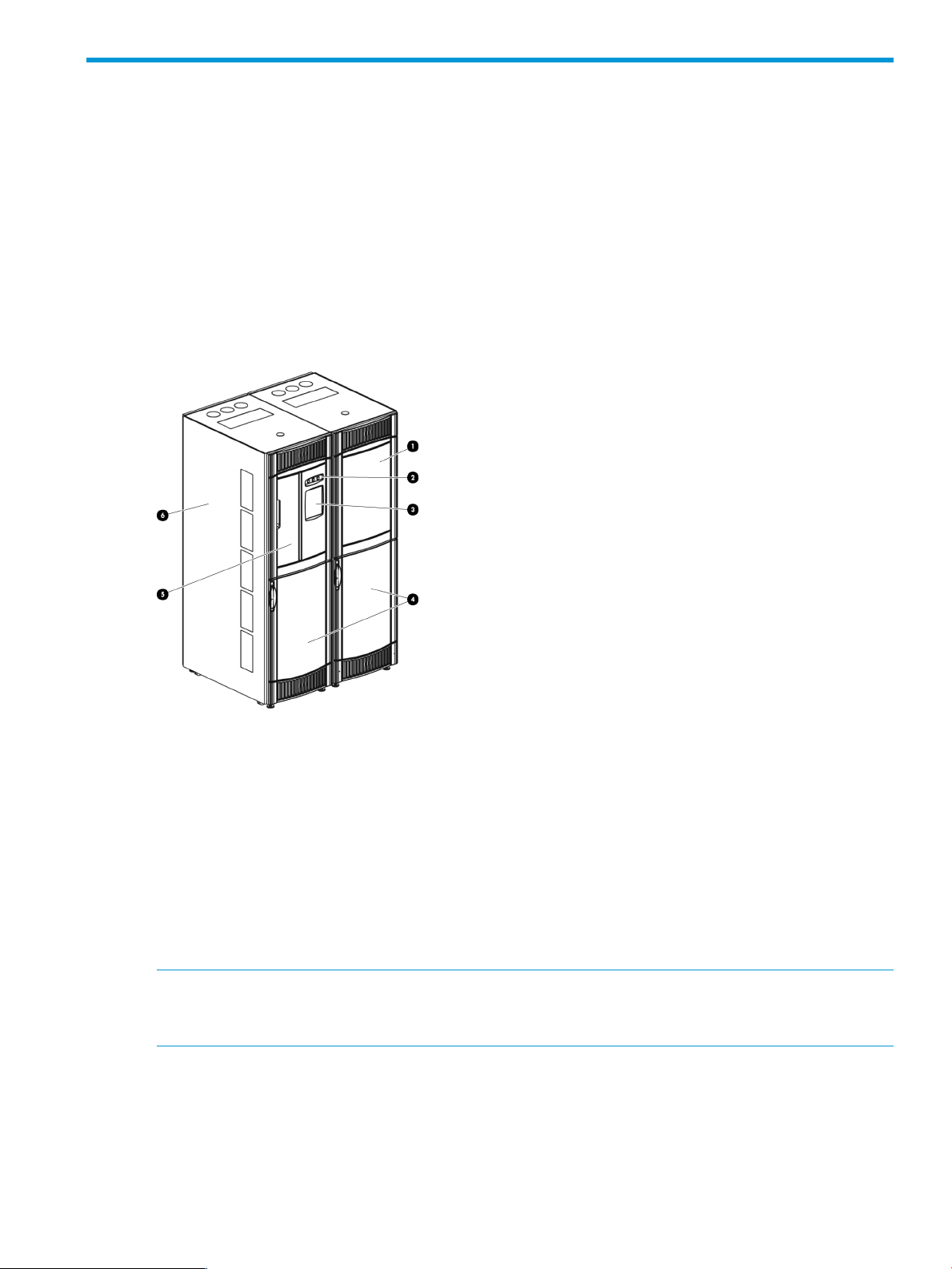
Figure 1 (page 11) shows a front view of the library, consisting of a control module and expansion
module.
Figure 1 Front view of a control module and expansion
2. Indicator panel1. Expansion module
4. Access doors3. Operator Control Panel (OCP)
6. Control module5. Import/Export station (I/E station)
The library is designed for ease of installation, configuration, and field upgrades.
The minimum library configuration of a single robot library consists of:
• One control module
• One left parking module
• One right parking module
NOTE: Expansion Modules are available in two types; standard Expansion Modules (EMs) and
High Density Expansion Modules (HDEMs). For more information, see “Expansion modules”
(page 15).
As your storage and tape drive requirements change, you can add additional Expansion Modules
to accommodate your needs.
The maximum library configuration is dependant on whether it is a single or dual robot library.
11
Page 12

A single robot library maximum configuration can accommodate:
• 1 control module
• 0 to 15 expansion modules
• 102 to 12,006 cartridges
• 1 to 192 tape drives
A dual library maximum configuration can accommodate:
• 1 control module
• 2 to 16 expansion modules
• 102 to 11,760 tape cartridges
• 1 to 192 tape drives
Hardware and firmware differences
Libraries shipped before June 2012 with Control Module SKU QQ007A are likely to be Hardware
Revision 1 (HW REV1). These libraries are characterized by:
• A multi-part accessor or picker
• An X-axis gear track system
• A Library Motor Drive (LMD) board in the Control Module
• Robot power via an umbilical cable along the floor of the library
• Removable calibration targets
• An accessor installed on the Y-rail
Libraries shipped after June 2012 with Control Module SKU QQ007B are likely to be Hardware
Revision 2 (HW REV 2) libraries. These libraries were introduced to support dual robot capability,
but all single robot libraries now use this architecture. HW REV 2 libraries are characterized by:
• A new one-piece robot
• An X-axis gear track system
• A Library Power Control (LPC1) board in the Control Module, replacing the LMD
• Robot power via a power rail system
• Calibration targets that are glued in place and in new locations
• A robot which is installed via a loader bracket
• Two new boards, the SPA and SCC, used to connect the Control Module to the left Parking
Module
A library's Hardware Revision can be identified on either the Library Management Console (LMC)
or through Library and Tape Tools (L&TT). On the LMC, the Hardware Revision is displayed
prominently on the main screen under the Status, Serial #, and Date.
NOTE: If there is no “HW Revision” text displayed on the LMC, this also indicates Hardware
Revision 1.
In L&TT, the Hardware Revision is displayed under Detailed Device Information→Device.
In this document, parts that are specific to one revision or the other are called out specifically. All
other parts are common between both library types.
12 Library overview
Page 13

Libraries shipped after May 2013 and running library firmware version 663H or later offer
additional features and configuration options, including:
• Support for HDEMs
• A new command-line interface (CLI)
• Anti-malware checks to make sure that firmware is certified by HP
• Active/Active robots, when dual robots are present
• More flexible drive placement among modules
• Two new boards, the MCB2.0 and RCU2.0, required to run firmware version 663H or later
NOTE: To enable these features, HW REV 2 libraries shipped between June 2012 and May
2013 require a Controller Board Upgrade Kit, purchased separately. HW REV 1 libraries, shipped
before June 2012, cannot access these features without first converting to the HW REV 2
architecture.
Library features
Density
The storage density of a library is dependent on several factors, including the type of expansion
modules utilized (standard or high density), the number of drives an expansion modules contains,
and I/E station usage. The maximum storage density of an EM is 758 cartridges (LTO) per square
meter. The maximum storage density of an HDEM is 1444 cartridges (LTO) per square meter. Each
module, also referred to as a frame, has two storage racks: one on the drive side and another on
the door side. A rack consists of up to 10 horizontal sections and three or four columns of
magazines, depending on the rack configuration. Each magazine, located at the intersection of
a particular section and a particular column, consists of six cartridge slots.
Centralized management
The Library Management Console (LMC) gives you a single point from which to view all library
components, including robotics, drives, storage, I/E stations, and network connectivity. You can
use this graphical user interface both locally from the library OCP and remotely from a remote
client. The LMC communicates with the LMC server that runs on the library. The LMC uses a simple
and intuitive graphical style that is secure and provides library managers with native partitioning
ability.
Proactive availability
The library can alert you about problems before they occur. The library also monitors its six major
subsystems (drives, power, robotics, cooling, connectivity, and control). You can configure the
library to send notifications of problems to one or more e-mail accounts. For more information
about the library monitoring and reporting capabilities see, “Maintaining the library” (page 132).
Data Path and Control Path Failover
For high availability on the Fibre Channel fabric, the ESL G3 tape library offers licensed failover
features for the drive data paths and the robot control paths. For both data path and control path
failover, basic and advanced failover modes are available.
Basic path failover uses library and drive firmware to create a new Fibre Channel path to a drive
or robot if the original path is lost. Most applications recognize the new path and some will
automatically retry commands after the original path is lost. Other applications may require user
intervention to begin using the new path.
Advanced path failover uses host drivers in conjunction with library and drive firmware to manage
multiple paths across multiple SANs, present a single drive or robot path to applications, and
Library features 13
Page 14

automatically transfer commands to the new path if the original path is lost. This transfer is invisible
to most applications, avoiding the need for user intervention.
IMPORTANT: Basic failover requires LTO-5 tape drives or later. Advanced failover requires LTO-6
drives or later, a supported host driver, and library firmware version 665H or later.
Serviceability and reliability
The library has extensive serviceability and reliability features. You can hot swap drives, power
supplies (in redundant power configurations only), fans, and many of the boards within the library.
Your backup system and data path are idle most of the time. When backups begin, the system is
used intensively at maximum bandwidth. The library provides you with notifications and a robust
event system that notifies you of any problems it identifies, enabling you to solve them before
backups begin. For more information about the library notification system, event system, and other
troubleshooting help, see “Troubleshooting your library” (page 186).
Host attachment
Requests issued from the host application result in cartridge movement in the library. The primary
requests issued are for mounting and dismounting cartridges in and out of the tape drives and for
importing and exporting cartridges in and out of the library. The library manages the physical
location. In addition to requesting cartridge movement in the library, the host application can use
the Fibre Channel (FC) command interface to obtain status information, configuration information,
and cartridge storage information from the library.
Tape drives are directly attached to host systems or to the SAN. The library robot control path is
presented through one or more tape drive ports, depending on Partitioning and Failover
configuration.
Remote management
The library can be managed locally or remotely using the LMC. Locally, the LMC appears on the
OCP on the front of the library. Remotely, the LMC is accessed through a client instance of the
LMC software on any computer on the network. For more information about access, see “Logging
on from the Library Management Console (LMC) using a web browser” (page 77). For more
information about the LMC, see “Accessing the Library Management Console (LMC)” (page 80).
The LMC provides additional monitoring of a SAN-attached library over the network to a
management server by using Simple Network Management Protocol (SNMP). This includes library
subsystem health and status information and early fault notification.
The library also supports the Common Information Model (CIM) server based on the Storage
Management Initiative Specification (SMI-S) on the MCB. A CIM client can use the CIM server to
monitor the SAN-attached library.
Capacity on demand
ESL G3 tape libraries can be purchased at starting points of 100, 300, 700, 1500, 3000, or
5000 cartridge slots enabled. Adding physical EMs/HDEMs does not automatically enable new
slots. Instead, slots are flexibly enabled for use in groups of approximately 100 through capacity
upgrade licenses.
Control module
All library configurations include the control module, which contains the following minimum
components (see Figure 2 (page 15)):
• Library management module (LMM)
• I/E station
14 Library overview
Page 15

• Tape drives
• Cartridge storage
• Operator panel
• Power system
• I/O Management Unit and Ethernet Expansion Blade (EEB)
Figure 2 Front and back view of the control module
Expansion modules
Expansion modules (also referred to as standard expansion modules or EMs) enable the library to
expand by adding space for tape drives, I/E stations, and cartridges. Each EM can add several
hundred LTO cartridge slots, depending on the number of tape drives installed and whether an
I/E station is installed. The library maximum configuration includes 15 EMs for a total of 16
modules. EMs can only be added to the right of the control module. See Figure 3 (page 16) and
Figure 4 (page 16).
NOTE: For libraries shipped before May 2013 and running a firmware version prior to 663H,
EMs in positions 9-12 are storage-only and do not contain I/E stations or drives.
For libraries shipped after May 2013 and running firmware version 663H or later, EMs can contain
I/E stations and drives throughout the library. Some restrictions apply, see “Import/Export stations”
(page 19) and “Tape drives” (page 22) for more information.
The EMs can accommodate the following components:
2. Control module front view1. Magazines and cartridge slots
4. I/E station3. Control module back view
6. I/O management unit5. Drive clusters
8. Power supplies7. Library management module
10. Accessor9. Picker
• I/O management unit (optional)
• Tape drives (optional)
• I/E station (optional)
Expansion modules 15
Page 16
• Cartridge storage
• AC power compartment (required only if drives are added)
If an EM contains only cartridges, all power is derived from the control module.
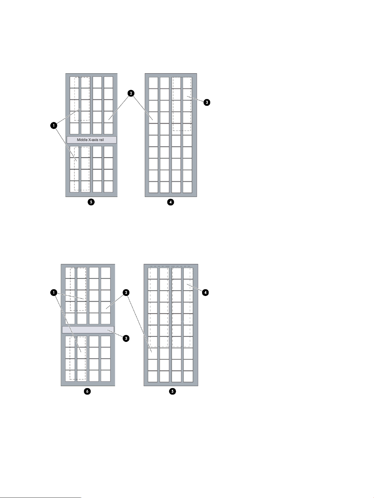
Figure 3 Expansion module with location of 24–slot I/E station
5. Drive side
Figure 4 EM with location of 72–slot I/E station
2. Cartridge magazines location1. Drive cluster (optional) location
4. Door side3. I/E station 24–slot (optional) location
An EM can have no I/E station, a 24–slot I/E station, or a 72–slot I/E station.
The 24–slot I/E station has a capacity of 24 LTO cartridges that are located in four removable
magazines.
16 Library overview
2. Magazines location1. Drive cluster (optional) location
4. 72–slot I/E station (optional) location3. Middle X-axis rail
6. Drive side5. Door side
Page 17

The 72–slot I/E station consists of two side-by-side 36–slot I/E stations that can operate as one
72–slot I/E station or can operate independently. Each 36–slot I/E station provides I/E capacity
of 36 LTO cartridges in six removable magazines.
NOTE: I/E stations are supported in all EMs, with the following exceptions in dual robot libraries:
• The left parking module cannot contain an I/E station.
• The last frame (also referred to as the right parking module) of a library cannot support a
72–slot I/E station.
High density expansion modules
High Density Expansion Modules (HDEMs) are storage-only modules that each contain a rotating
tower of storage magazines, allowing for a larger number of storage slots in the same footprint
as a standard expansion module. The HDEMs can only be added to the right of the control module.
NOTE: HDEMs are storage-only modules and do not contain drives. If you have a dual robot
library, HDEMs cannot be used as the left or right parking modules (the modules furthest left or
right).
HDEMs, in a dual robot library, can accommodate the following components:
• I/E station (optional)
• Cartridge storage
• Redundant power supply (optional)
NOTE: HDEMs are only available in HW Rev 2 libraries.
HDEMs are only supported in libraries that were purchased after May 2013 or libraries that have
been upgraded with the Controller Board Upgrade Kit, purchased separately.
Library management module
The library management module (LMM) controls and manages library hardware and software
components. It enables both SAN-connected hosts and users who access the library using the
operator panel to configure the library, obtain system status information, and perform various
library functions. The LMM contains the management control blade (MCB), the robotics control
unit (RCU), and the library motor drive (LMD) or Library Power Control (LPC1), as shown in
Figure 5 (page 18).
High density expansion modules 17
Page 18
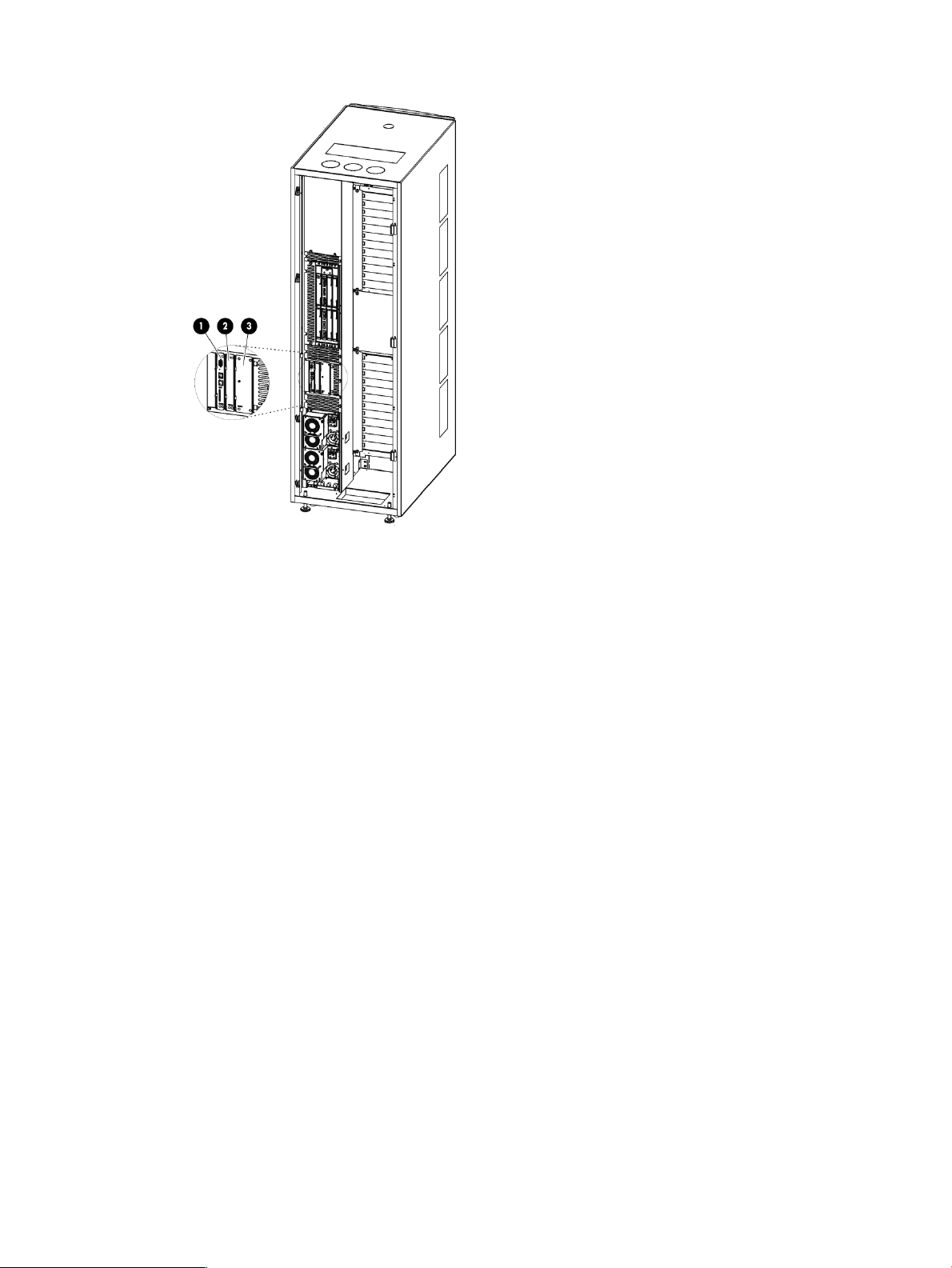
Figure 5 Library management module boards
1. Management control blade
2. Robotics control unit
3. Library motor drive (LMD) or Library power control (LPC1)
Management control blade (MCB)
The MCB is the primary point of intelligent management in the library. The MCB stores firmware
and configuration data for itself as well as most other intelligent components in the library. It also
contains the LMC, which enables local or remote users or hosts to operate, configure, and monitor
the library. The MCB collects status information on other components in the library and issues
notifications when problems occur.
The MCB Version 2 also has two Ethernet ports, allowing the library to be on two different networks.
This provides both additional redundancy as well as greater configuration flexibility.
Robotics control unit (RCU)
The RCU provides robotics intelligence that controls accessor movements and functions, including
picker, pivot, and reach actions.
Library motor drive (LMD) or library power control (LPC1)
The LMD/LPC1 monitors wiring, fuses, and relays within the library. It regulates power levels and
performs other power-related functions, such as disabling robotics when a library door opens.
I/O Management units
The I/O management unit supports the control management blade (CMB) and the Ethernet Expansion
Blade (EEB).
18 Library overview
Page 19

Control management blade (CMB)
The CMB performs unit status monitoring, including power and I/O present conditions. The CMB
also enables you to update drive firmware without using a firmware update (FUP) tape.
Ethernet expansion blade (EEB)
The EEB provides Ethernet connectivity to each LTO drive for MCB-to-drive communication purposes
only. The EEB is not in the data path. This EEB provides a control path to the drive for commands
as well as facilitates taking drive logs and downloading drive firmware. Each EEB has 6 Ethernet
ports to allow attachment to 6 LTO drives. The EEB provides Ethernet connectivity to the library
internal Ethernet and should not be connected to an external Ethernet source.
Picker (cartridge accessor)
The picker moves cartridges between storage cells, tape drives, and I/E stations. A picker is used
to Get or Put cartridges in a storage cell or a tape drive slot. It moves along an X and Y axis and
can pivot 180 degrees. A barcode scanner on the picker assembly identifies cartridges located
in storage slots.
Import/Export stations
I/E stations enable you to import and export cartridges without interrupting normal library
operations. A 24–slot I/E station comes installed on the front of the control module. Optionally,
additional I/E stations can be added to both standard EMs and HDEMs in larger libraries. See
Figure 1 (page 11) and Figure 2 (page 15) to see the location of the I/E station.
Each 24-slot I/E station contains four removable magazines for a total of 24 LTO tape cartridges.
Each 72-slot I/E station contains twelve removable magazines for a total of 72 LTO tape cartridges.
NOTE: The I/E station cannot be configured as a storage location, but it can be part of a logical
division of library resources known as partitions. For information about partitions, see “Working
with partitions” (page 27).
A library I/E station configuration can accommodate one 24–slot I/E station in the control module
and up to seven 72–slot I/E stations, with a maximum of 528 I/E slots per library. The I/E station
placement options available in your library are dependent on the date of purchase and firmware
version installed on your library:
• Libraries shipped before May 2013 and running a firmware version prior to 663H, I/E stations
cannot be placed in EMs in positions 9–16.
• Libraries shipped after May 2013 and running firmware version 663H or later, I/E stations
can be placed in EMs throughout the library.
NOTE: If you have a dual robot library, the left parking module cannot contain an I/E station.
If you have a dual robot library, the last frame (also referred to as the right parking module) of a
library can support a 24–slot I/E station but cannot support a 72–slot I/E station.
Extended I/E option
The number of I/E slots in a library is usually associated with the number of I/E slots in an actual
physical I/E station, but this physical slot count might limit how many I/E slots are available to a
host application.
Extended I/E configurations remove such limitations by increasing the I/E slot count for a partition
with storage slots that will be reported to a host as I/E slots. Therefore, Extended I/E allows you
to configure partitions with I/E slots beyond the number of physical I/E slots configured in the
library. As a result, the host can export more media than previously allowed.
Picker (cartridge accessor) 19
Page 20

Keep in mind that as Extended I/E slots are used, less storage slots are available. You will need
to initiate the move/import operations of tape cartridges into the extended I/E area for host access.
Conversely, to move/export tape cartridges from Extended I/E area slots to the emptied physical
I/E Station slots, you need to initiate the move/export operation from the user interface for physical
access to the library.
NOTE: By default, the Extended I/E feature is disabled. Extended I/E can be enabled/disabled
from the Physical Library dialog box.
To configure a partition with Extended I/E segments, the user must use the Partition Wizard
(Setup→Partition→Configure). The Extended I/E feature is only available in Expert creation mode
or if you are modifying an existing partition. See “Creating partitions manually using Expert mode”
(page 32).
Extended I/E must be enabled before using it. When configuring Extended I/E:
• Ensure you have enough licensed slots (Capacity On Demand - COD) to accommodate the
• Ensure you have at least one physical I/E segment configured in the partition. The maximum
Cartridges
Cartridges are stored in magazines within the library, as shown in Figure 6 (page 20).
new Extended I/E slots, since the slots use the COD licensed slot count.
number of physical and Extended I/E slots per partition is 240.
Figure 6 Example of LTO cartridge insertion into a magazine
2. Magazine barcode1. LTO cartridge
4. Cartridge barcode location3. LTO magazine
Each cartridge has an operator-attached, machine-readable barcode label on it for identification
purposes. The library can dynamically support barcode labels that consist of up to thirteen characters
plus a two character media identifier, for a total maximum of fifteen characters. However, it is
always recommend that HP barcode labels are used, which are comprised of a six character
cartridge identifier followed by a two character media identifier, for a total of eight characters. .
For more information about tape cartridges, see “Tape drives” (page 22).
For additional barcode label specification information, see “Barcode requirements” (page 169).
Cartridge magazines
The cartridge magazine is a storage assembly that installs on the drive side or door side of the
control module, expansion module, or high density expansion module as shown in Figure 7
20 Library overview
Page 21

(page 21). It contains 6 cartridge slots and provides flexibility when adding storage cartridges to
a module.
See Table 1 (page 21) for cartridge capacities.
Figure 7 Magazine and drive locations in the control module (left) and on the control module access
door (right)
2. Upper drive cluster1. Lower drive cluster
4. Middle X-axis rail3. Cartridge magazines
6. I/E station cartridge magazines5. I/E station
8. Drive side7. Door side
10. Drives or cartridge magazines9. Lower drive ports
11. Upper drive ports
Table 1 Cartridge capacities in library modules
5
HDEM
Cartridge
Capacity
612 min /
780 max
4
Magazines
per HDEM
102 min /
130 max
3
EM
Cartridge
Capacity
192
min/456
max
Type of
cartridge
Cartridges
per
magazine
Magazines per
Control Module
Magazines
1
per EM
2
Control
Module
Cartridge
Capacity
44 min/50 max6LTO
32 min/76
max
264
min/300
max
1
The minimum is based on having 12 drives installed. The maximum is based on having one drive and one I/E station
installed.
2
The minimum is based on having an I/E station and 12 drives installed. The maximum is based on having no drives and
no I/E station installed.
3
The minimum is based on having 12 drives installed. The maximum is based on having one drive and one I/E station
installed.
4
The minimum is based on having an I/E station and 12 drives installed. The maximum is based on having no drives and
no I/E station installed.
5
The minimum is based on having no drives and a 72-slot I/E station installed. The maximum is based on having no drives
and no I/E stations installed.
5
Each magazine has a barcode label that the scanner reads for identification and inventory. An
optional, snap-on dust cover is available for the magazines. Magazines with the dust cover have
Cartridge magazines 21
Page 22

interlocked stacking that enables easier storage of the media when they are removed from the
library for external storage.
Support for WORM
The ESL G3 library supports WORM (write once, read many) technology in LTO-4 and later tape
drives.
WORM allows non-erasable data to be written once and provides extra data security by prohibiting
accidental data erasure.
Tape drives
Tape drives are enclosed in a universal drive sled. You can hot swap and hot add all supported
drives, regardless of type. The library supports HP LTO-4 and later FC Multi-mode tape drives.
The control module and expansion modules have upper and lower drive clusters. Each library must
have at least one tape drive. Each drive cluster can house up to six tape drives for a total of 12
drives. Additional drives can be added to standard EMs both consecutively and non-consecutively,
with a maximum of 192 drives per library, with current hardware and firmware.
NOTE: When you add drives, you lose storage slots.
For libraries shipped before May 2013 and running a library firmware version prior to 663H,
drives must be installed in bottom to top order in the CM, filling the module with 12 drives, before
any are added to the first EM. Additionally, the first EM must have all 12 drives installed in the
same order before adding any drives to the next EM..
For libraries shipped after May 2013 and running library firmware version 663H or later, drives
can be installed throughout the CM and EMs consecutively or non-consecutively, as long as the
control module contains at least one drive. However, drives should still be added to the CM and
any additional EMs in bottom to top order.
NOTE: The term drive cluster defines a grouping of up to six tape drives below or above the
middle X-axis rail.
Figure 7 (page 21) shows the locations of drives in the control module.
LTO drives
LTO drives are supported as shown in Table 2 (page 22).
Table 2 LTO drive and cartridge compatibility
All LTO cartridges are the same size, which means they use the same magazines in the library.
LTO drives can be directly attached to hosts but for full functionality they should be integrated in
a SAN.
LTO-6 CartridgeLTO-5 WORMLTO-5 CartridgeLTO-4 WORMLTO-4 Cartridge
Reads/WritesLTO-4 Drives
Many
Reads/WritesLTO-5 Drives
Many
Reads/WritesWrite Once, Read
Many
Reads/WritesReadsReadsLTO-6 Drives
Many
Not compatibleNot compatibleNot compatibleWrite Once, Read
Not compatibleWrite Once, Read
Reads/WritesWrite Once, Read
22 Library overview
Page 23

Operator panel
The operator panel is located on the front of the control module and consists of the indicator panel
and the OCP (see Figure 8 (page 23)). In the indicator panel, the buttons are for robot control and
power, and the indicators provide library status.
Figure 8 Operator panel
2. Power indicator/button1. Status indicator
4. Robotics enabled indicator/button3. OCP
The OCP is the library navigation point and provides access to the LMC. For more information
about the OCP and the LMC, see “Accessing the Library Management Console (LMC)” (page 80).
Power system
The library supports single and redundant power configurations. The single configuration has a
single AC line input and single DC power supply. The redundant configuration has dual AC line
input and dual DC power supplies. You can hot swap a power supply if you have a redundant
power supply. You can hot add a second power supply.
The power system consists of the following:
• Power supply
• Power distribution unit (PDU)
• AC power cord
A single power switch, located on the access door, turns on and off all power for the control module
and attached standard or high density expansion modules. Each PDU has a second circuit breaker,
located in the rear of the module, that controls the module power supply output. The power supply
has three LEDs that provide status information. The power system also has four fuses for system
protection.
Using the library demonstration mode
By running the library in demonstration (demo) mode, you can demonstrate the ability of the library
to move scratch media from an I/E station to a randomly selected storage slot, and then move
media from storage slot to open storage slot until you pause or stop the demonstration.
Non-demonstration media in the storage racks are not affected by the demonstration. While the
demonstration proceeds, graphs on the main LMC display show data transfer and mount statistics
using data that the demonstration routine provides. Demo mode is available only from the library
OCP.
Operator panel 23
Page 24

Starting demo mode
To start the demo mode:
1. Log onto the library from the local OCP as the Service user.
2. Make sure that no applications are accessing the library.
3. If you are not already working from the physical library, from the View menu, click the name
of the physical library. See “Viewing the physical library or a partition” (page 93) for more
information on viewing the library.
4. Take the library offline.
5. Select Service→Start Demo.
A Start Demo message appears.
6. Remove any non-demonstration cartridges from the I/E station, and then put one or more
demonstration cartridges into the I/E station.
CAUTION: Any cartridges left in the I/E station will be used in the demonstration.
7. Select OK when you are ready to start the demonstration.
Before the demonstration starts, the library performs an inventory. As the accessor moves
cartridges, an intentional delay of two seconds occurs between move media commands. This
prevents unnecessary wear on the robotics.
CAUTION: Do not take the library back online while the demo is running.
Pausing demo mode
You can pause the demonstration anytime while it is in progress. To do so:
1. While the demonstration is in process, select Service→Pause Demo.
The current SCSI command completes before the library returns control to you. For example,
if the library is performing an inventory, it could take several minutes before the inventory
command completes.
While the demonstration is paused, you can open an access door, take the library online, or
perform any library operation.
2. To continue the demonstration at the point at which you paused it, select Service→Resume
Demo.
The demonstration will start again where it left off.
Stopping demo mode
To stop the demo mode, select Service→Stop Demo.
The current command will complete before the accessor returns the demo cartridges to their original
slots in the I/E station.
24 Library overview
Page 25

2 Modifying the library configuration
Before you can manage your library from a remote Library Management Console (LMC) client,
you must initially configure the library from the Operator Control Panel (OCP) on the library itself
by either running the Setup Wizard command or using individual configuration commands from
the Setup menu.
After the initial setup, you can use either the OCP or the LMC to modify your library configuration.
The Setup menu includes most of the configuration commands.
NOTE: Only one administrator can be logged on and performing library configuration at any
one time. If another administrator attempts to log on, a message appears, warning that only one
administrator at a time is permitted on the library. If a service user logs on while an administrator
or regular users are logged on already, the library automatically logs off those users.
Setup Wizard prerequisites
Before you run the Setup Wizard:
• Note the name and IP address of your network Domain Name Server (DNS) or the IP address,
subnet mask, and default gateway for your network segment.
• Verify that your network is attached to the library network connection.
Accessing the Setup Wizard
Before using the Setup Wizard, see “Setup Wizard prerequisites” (page 25).
To access the setup wizard from the OCP or the LMC:
1. Log on as administrator. The home screen appears.
2. Verify in the System Information section, in the Name field that the physical library is selected.
If necessary, select it by one of the following methods:
• In the Managed Views section of the screen, click on the name of the physical library.
• From the menu bar, select View, then the name of the library.
3. Click Setup→Setup Wizard to display the About Setup Wizard screen.
4. Use the buttons at the bottom of the wizard dialog box to navigate to the procedures you want
to perform. The procedures available from the Setup Wizard are:
• “Entering License Keys” (page 25)
• Setting up partitions (see “Creating partitions” (page 29), “Modifying partitions” (page
35), and “Deleting partitions” (page 38))
• “Enabling or disabling IPv6 and IPv4 network configuration” (page 42)
• “Specifying the date and time using the Setup Wizard” (page 46)
Entering License Keys
Enable license keys in the following situations:
• During initial installation and configuration of the library.
• During a capacity on demand (COD) or feature upgrade.
• When enabling ESKM. See “Enabling the ESKM License Key” (page 221) for specific instructions.
• When enabling KMIP. See “Using the Key Management Interoperability Protocol (KMIP)
feature” (page 224) for specific instructions.
If you cannot locate the license instructions shipped with the library, you can obtain them by
contacting HP Support.
Setup Wizard prerequisites 25
Page 26
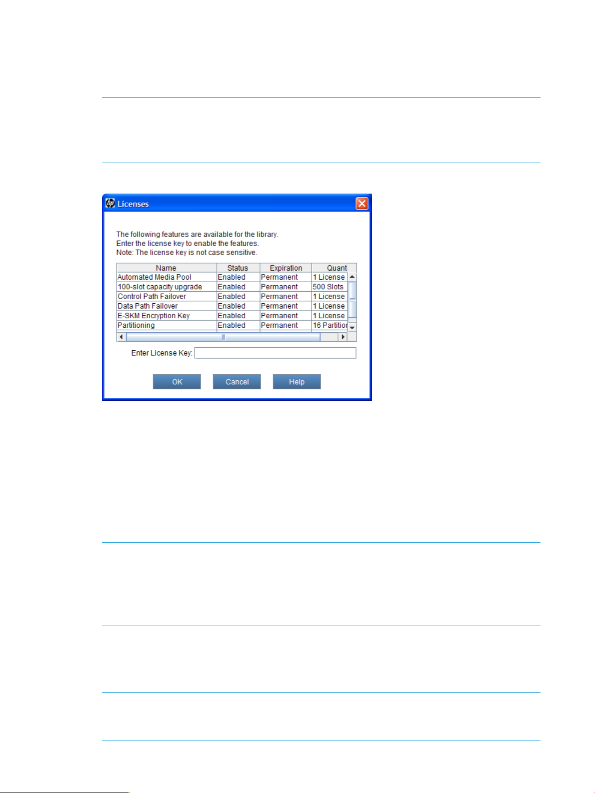
To enable licenses:
1. Log on as an administrator.
2. If you are not already working from the physical library, select it from the View menu.
3. From the menu bar, click Setup→Licenses.
NOTE: To perform this procedure from the Setup Wizard, select Setup→Setup Wizard, then
click Next until the Licenses dialog box appears.
Only run the Setup Wizard to perform initial library configuration. Use other appropriate menu
options to modify the configuration.
The Licenses dialog box appears.
This dialog box lists the licensed features for your library, including their status, expiration
date, and quantity. The following guidelines apply to Quantity:
• The COD quantity is the number of slots licensed.
• The partition quantity is either 1 or 16. The only possible multiple number of partitions is
16.
• For features that are not licensed by quantity, such as Automated Media Pool, Quantity
is always set to 1.
4. In the Enter License Key text box, type the appropriate license key.
NOTE: You do not need to highlight the feature before you enter a license key.
License keys are not case-sensitive, so if you are using the library OCP, enter the library key
from the lowercase keyboard, which gives you access to the dash (-) character.
If you cannot locate the license instructions shipped with the library, you can obtain them by
contacting technical support or, if you are an end user, by contacting your sales representative.
5. Click OK.
If you have upgraded the library storage capacity, the extra storage slots you just added are
not assigned to a partition. You can either create a new partition to include them or manually
modify an existing partition to include them by using expert partitioning mode.
NOTE: Command View TL version 2.8 or later must be used to enter the TC347A license
key for Command View TL software. Command View TL can also be used to launch the LMC,
enter additional license keys, and enable TapeAssure.
26 Modifying the library configuration
Page 27

For more information, see “Working with partitions” (page 27).
Working with partitions
A partition is an abstraction of a single underlying physical library that presents the appearance
of multiple, separate libraries for purposes of file management, access by multiple users, or
dedication to one or more host applications. For example, you can choose to run one software
application in one partition, and a different software application in a second partition.
Each partition contains the following components of the physical library:
• Accessor: the robotic assembly that moves media within the library. The accessor includes the
picker and reach assemblies.
• I/E station magazine: a magazine, consisting of slots for cartridges, that enables media to
be moved into or removed from the physical library. The type of media determines the number
of slots in the magazine. For example, an LTO magazine has six slots.
• Storage magazine: a static column location within a section of the physical library rack that
holds removable media. For more about location coordinates, see “Understanding location
coordinates” (page 88).
• Drive: the read/write device for removable media.
A partition consists of, at a minimum, one storage magazine and one drive. Neither the storage
magazine nor the drive can be shared with another partition. Each partition is specific to a media
type (for example, LTO tape drives). One 24–slot I/E station can be used by up to four partitions.
One 72–slot I/E station can be used by up to twelve partitions. The maximum number of I/E station
slots per partition is 240. The maximum number of partitions is determined by the lesser of either
the number of drives available in the physical library (assuming there are at least as many storage
slots), or 16.
NOTE: The library is licensed for either one partition or the maximum number of partitions, which
is 16.
Using the Secure Manager feature, multiple hosts can share a single partition, or a partition can
be restricted to one exclusive host.
Each host application can have a partition assigned to it. Each application uses its partition as if
it were a dedicated physical library.
Understanding partition media policy settings
The partition Media Type Checking Policy and Return Media Identifier settings help determine how
the library handles differing media types within the same library. Configure media policy settings
when you manually create or modify a partition.
Media domain
The media domain is the family of all cartridge types that can be stored in the same storage slot.
Typically, a media domain represents all the generations and brands of a particular tape technology.
For example, Linear Tape Open (LTO) has many generations and vendors, but all LTO cartridges
are considered to exist in the same media domain.
Media type
The media type is a particular generation of tape technology. Several media types can exist within
one media domain. Using LTO again as an example, within the LTO media domain is the LTO-4
media type, the LTO-5 media type, and so forth. A media type has an identifier, chosen by the
tape manufacturer or consortium, that enables users and libraries to distinguish between them. The
LTO consortium uses L4, L5, and L6 to identify the LTO-4, LTO-5, and LTO-6 media types in a
volume serial number.
Working with partitions 27
Page 28

Media ID checking
Media ID checking policy restricts the movement of tape cartridges based on the media ID on the
barcode label. This policy also helps you monitor the management of tapes and drives by the host
applications. When you create or modify a partition, you can enable or disable the Media Type
Checking option. If you choose to enable media type checking, you also can use the Media Checking
Policy option to select from two modes of operation: Required or Not Required. With either mode,
the library checks whether a cartridge has a valid media ID on the barcode label.
In Required mode, if the library does not find a valid media ID on a cartridge, the library does not
allow it to be moved into or within the library. If the library finds a valid media ID, the library
allows it to be moved from an I/E station into a partition that contains magazines matching the
media domain of the cartridge (for example, LTO), but the library does not allow the cartridge to
be moved from storage to a drive that does not have a matching type (for example, an LTO-5
cartridge will not be allowed to move to an LTO-4 drive).
In Not Required mode, if the library does not find a valid media ID on a cartridge, the library
allows it to be moved into or within the library as long as the I/E station magazine, storage
magazine, or drive matches the media domain of the cartridge. If the library finds a valid media
ID, the library does not allow the cartridge to be moved from storage to a drive that does not have
a matching type (for example, an LTO-5 cartridge will not be allowed to move to an LTO-4 drive).
Return media identifier
For the media policy settings, the library makes assumptions about a media identifier and its
position in a media barcode label. To be considered a media identifier, the identifier characters
must be correct for the media domain and media type. Also, the identifier, which for some media
types can consist of more than one character, must be complete and in the correct location. The
correct characters in the wrong position are not viewed as a media type identifier. In a physical
library or partition containing mixed media, the media identifier is not required for all cartridges.
Table 3 (page 28) explains the media type identifiers and assumptions.
Table 3 Sampling of media type identifiers
With a valid media type identifier present and the Media Type Checking setting enabled (default)
a host is prevented from executing invalid media moves across differing media types. For example,
a host can be prevented from moving LTO-5 media to an LTO-4 drive. If an invalid move is
attempted, the library returns an error to the host.
Returning media identifiers to hosts
With the Return Media Identifier setting, you can control if and where a media type identifier
appears in the volume serial number that is returned to the host.
Table 4 (page 29) shows an example of how the return media identifier behaves, depending on
the setting you choose. The bold, underlined portion is the media identifier.
IdentifierMedia typeMedia domain
LTO-4LTO
LTO-4 WORMLTO
LTO-5LTO
LTO-5 WORMLTO
LTO-6LTO
“L4” as the last two characters in the
barcode
“LU” as the last two characters in the
barcode
“L5” as the last two characters in the
barcode
“LV” as the last two characters in the
barcode
“L6” as the last two characters in the
barcode
28 Modifying the library configuration
Page 29

Table 4 Return media identifier behavior example
Setting
1
Based on actual LTO-5 barcode: AB1234L5
For more information about configuring the Media Type Checking and Return Media Identifier
settings, see “Creating partitions” (page 29).
Working with library control paths
You must define a control path for each library partition. The ESL G3 does not automatically assign
a control path when you create a partition that will need to perform media moves. When selecting
a library control path for a partition, you are selecting which tape drive will present (or proxy) the
virtual robot LUN to the SAN and hosts.
NOTE: If a control path isn't configured for a partition, any hosts connected to this partition will
be unable to perform media moves, as no robot LUN will be presented to those hosts.
Volume serial number returned to host
AB1234Disabled
L5AB1234Prefix
AB1234L5Suffix
AB1234L5Pass Through
1
Creating partitions
You can create library partitions in the following ways:
• “Creating partitions with the Setup Wizard” (page 29)
• “Creating partitions automatically” (page 30)
• “Creating partitions manually using Simple mode” (page 30)
• “Creating partitions manually using Expert mode” (page 32)
The method you should choose depends on the circumstance and the level of control you want in
allocating resources to the partition. In Automatic mode, the library assigns available system
resources to create the number of partitions you specify. Automatic mode is not available if a
partition already exists. Manual mode enables you to pick specific drives, storage magazines,
and magazines within an I/E station to assign to a partition.
If one or more partitions already exist in the library, you must manually create a new partition to
allocate drives, storage slots, and I/E station magazines. You have two options to allocate system
resources when manually creating a new partition: Simple and Expert modes. In Simple mode,
you can specify the quantity of each element you want assigned to the partition. In Expert mode,
you can indicate which specific drives, storage magazines, I/E station magazines, or if enabled,
extended I/E station magazines to assign to the partition.
NOTE: Make sure that you have adequately planned for the number of partitions that you want
to configure.
Creating partitions with the Setup Wizard
If you are performing an initial configuration of your library, you can use the Setup Wizard to
automatically create partitions using the available system resources. See “Creating partitions
automatically” (page 30). Using the Setup Wizard is part of the normal installation procedure for
a library.
Working with partitions 29
Page 30

NOTE: You should run the Setup Wizard only when you initially configure the library.
The Automatic radio button will be disabled if there are partitions already configured. This indicates
that the Setup Wizard has already been run and you should create partitions by using
Setup→Partitions. See “Creating partitions manually using Simple mode” (page 30) or “Creating
partitions manually using Expert mode” (page 32).
Creating partitions automatically
You can use the library Automatic mode to create partitions within limits based on licensing
restrictions and available resources. Automatic mode is available only if no partitions currently
exist.
To create partitions automatically:
1. Log on as an administrator.
2. Ensure that you are viewing the physical library. From the View menu, click the name of the
physical library.
3. Select Setup→Setup Wizard, then click Next until the Partitions dialog box appears.
Alternatively, click Setup→Partitions→Configure.
The Partitions dialog box appears.
4. Click Create.
The Partitions: Choose Creation Mode dialog box appears.
5. Select Automatic, and then click Next.
NOTE: Automatic is only available if no partitions currently exist. If it is not available, see
“Creating partitions manually using Simple mode” (page 30) or “Creating partitions manually
using Expert mode” (page 32) to create partitions.
The Partitions: Automatic Creation dialog box appears.
6. In the Partitions column, type the number of partitions you want to create for each media/drive
type.
The maximum number of partitions that you can create is determined by the number of partitions
you are licensed to create and the number of drives available.
7. Click Create.
8. Click Finish.
The Partitions dialog box appears again.
9. If you are in the Setup Wizard, click Next to continue, or click Cancel to exit the Setup Wizard.
If you are not in the Setup Wizard, click Close.
Creating partitions manually using Simple mode
In Simple mode, you can specify the quantity of each element you want assigned to the partition.
To create partitions manually using simple mode:
1. Log on as an administrator.
2. Make sure that you are viewing the physical library. From the View menu or in the Managed
Views region of the LMC, click the name of the physical library.
3. Click Setup→Partitions→Configure.
The Partitions dialog box appears, listing partitions that are currently configured within the
library.
30 Modifying the library configuration
Page 31

NOTE: To perform this procedure from the Setup Wizard, select Setup→Setup Wizard, then
click Next until the Partitions dialog box appears.
Only run the Setup Wizard to perform initial library configuration. Use the appropriate other
menu option to modify the configuration.
4. Click Create.
The Partitions: Choose Creation Mode dialog box appears.
5. Select Simple, and then click Next.
The Partitions: Choose Partition Properties dialog box appears.
6. Configure the following settings:
• In the Name text box, type a name that describes the new partition.
• From the Drive Domain drop-down list, click the appropriate drive domain.
7. To continue, click Next.
The Partitions: Choose Policy Settings dialog box appears.
8. Configure the media type checking and media identifier settings:
• For Media Type Checking, select either Enable or Disable. This setting is enabled by
default.
• From the Media Checking Policy drop-down list, click either Required or Not Required.
• From the Return Media Identifier drop-down list, click either Suffix, Pass Through, Prefix,
or Disabled. Depending on which setting you choose, you can control the use of the
media type identifier in the volume serial number that is returned to the host.
CAUTION: After a media volume serial number has been reported to a host, changing
the Return Media Identifier setting could cause the host to not recognize media within the
library.
For more information about how media policies work, see “Understanding partition media
policy settings” (page 27).
• For Automatic Drive Cleaning, select Enable if this functionality is desired. This setting is
disabled by default.
NOTE: Periodic drive cleaning allows drive cleaning to be scheduled for pre-determined
intervals. This functionality is only supported with LTO-5 and newer drives.
Enabling automatic drive cleaning allows the library to initiate drive cleaning each time
a drive requests a cleaning operation. For automatic drive cleaning to function, you must
first configure drive cleaning for the library (see “Configuring drive cleaning” (page 61)).
NOTE: Automatic drive cleaning should be enabled for partitions only if the host
application does not support the coordination of drive cleaning. If drive cleaning
functionality is enabled on the host application, do not enable automatic drive cleaning
for any partitions in the library.
9. To continue, click Next.
The Partitions: Choose Resource Quantities dialog box appears.
Working with partitions 31
Page 32

10. Type the number of elements to include in the partition by specifying:
• Number of drives
• Number of storage slots
• Number of I/E slots
The quantity available for each type of resource indicates resources not yet assigned to existing
partitions.
11. To continue, click Next.
The Partitions - Summary Information dialog box appears.
12. Verify that the parameters you set are correct.
13. To create the partition, click Create.
NOTE: After you click Create, the Cancel button becomes unavailable.
The Partitions - Completed dialog box appears.
14. Review the information to make sure it is correct.
15. If you want to view the drive information after creating the partition, click Next.
16. Click Finish.
The Partitions dialog box lists the partition you just created.
17. If you are in the Setup Wizard, click Next to continue to IPv6 Configuration, or click Cancel
to exit the Setup Wizard. If you are not in the Setup Wizard, click Close.
Creating partitions manually using Expert mode
In Expert mode, you can indicate which specific drives, storage magazines, I/E station magazines,
or if enabled, extended I/E station magazines to assign to the partition.
To create partitions manually using expert mode:
1. Log on as an administrator.
2. Make sure that you are viewing the physical library. From the View menu or in the Managed
Views region of the LMC, click the name of the physical library.
3. Click Setup→Partitions→Configure.
The Partitions dialog box displays a list of partitions currently configured within the library.
NOTE: To perform this procedure from the Setup Wizard, select Setup→Setup Wizard, then
click Next until the Partitions dialog box appears.
Only run the Setup Wizard to perform initial library configuration. Use the appropriate other
menu option to modify the configuration.
4. Click Create.
The Partitions: Choose Creation Mode dialog box appears.
5. Select Expert, and then click Next.
The Partitions: Choose Partition Properties dialog box appears.
6. Configure the following settings:
32 Modifying the library configuration
Page 33

NOTE:
If you are creating an Automated Media Pool (AMP) partition, do the following:
a. Ensure that the AMP license is installed.
b. Name the partition, select the slot magazines to include in the partition, and select the
I/E station slots to include in the partition.
c. Go to 7.
If you are not creating an AMP, do the following:
a. In the Name text box, type a name to describe the new partition.
b. From the Drive Domain drop-down list, click the appropriate drive type.
7. To continue, click Next.
The Partitions: Choose Policy Settings dialog box appears.
NOTE: If you are configuring the AMP, all fields are greyed out and do not allow input. Go
to 9.
8. Configure the following settings:
• For Media Type Checking, select either Enable or Disable. This setting is enabled by
default.
• From the Media Checking Policy drop-down list, click either Required or Not Required.
• From the Return Media Identifier drop-down list, click either Suffix, Pass Through, Prefix,
or Disabled. Depending on which setting you choose, you can control the use of the
media type identifier in the volume serial number that is returned to the host.
CAUTION: After a media volume serial number has been reported to a host, changing
the Return Media Identifier setting could cause the host to not recognize media within the
library.
For more information about how media policies work, see “Understanding partition media
policy settings” (page 27).
• For Automatic Drive Cleaning, select Enable if this functionality is desired. This setting is
disabled by default.
NOTE: Periodic drive cleaning allows drive cleaning to be scheduled for pre-determined
intervals. This functionality is only supported with LTO-5 and newer drives.
Enabling automatic drive cleaning allows the library to initiate drive cleaning each time
a drive requests a cleaning operation. For automatic drive cleaning to function, you must
first configure drive cleaning for the library. (See “Configuring drive cleaning” (page
61).
NOTE: Automatic drive cleaning should be enabled for partitions only if the host application
does not support the coordination of drive cleaning. If drive cleaning functionality is enabled
on the host application, do not enable automatic drive cleaning for any partitions in the library.
9. To continue, click Next.
The Partitions: Select Drives dialog box appears.
10. In the left column, select the location of one or more drives.
Make sure that you select the appropriate module, because the library can have drives in the
control module and any of the standard expansion modules.
Working with partitions 33
Page 34

11. To assign a drive to the partition, select the appropriate check box. You can identify a drive
by its serial number and location coordinates. For more information, see “Understanding
location coordinates” (page 88).
12. To continue, click Next.
The Partitions: Select Storage Slots dialog box appears.
When you are selecting storage slots to be part of the partition, if you have the AMP license
installed you can also add magazine extensions to the partition that can be used to extend
the partition for future growth via the AMP partition slots. For each extension you add, the
library will report those extensions as inaccessible slots until you assign magazines from the
AMP partitions to this partition.
13. In the left column, select the location of one or more I/E station magazines.
14. To assign a storage slot, select the appropriate check box. You can identify a storage slot by
its location coordinates. The number of slots available is determined by the drive media type.
15. To continue, click Next.
The Partitions: Select I/E Slots dialog box appears.
16. Select the location of one or more I/E station magazine.
a. Make sure that you select the appropriate module because the library can have I/E
stations in the control module and any attached standard or high density expansion
modules.
b. To assign an I/E station magazine, select the appropriate check box. You can identify
an I/E station magazine by its location coordinates.
17. If Control Path Failover (CPF) license is installed, you are able to select which drive will be
the failover drive. Select the appropriate drive, and then select whether you want to enable
Basic or Advanced Control Path Failover.
18. If Data Path Failover (DPF) license is installed, you are able to select which drive will use DPF.
For each drive within the partition, select whether you would like to enable Basic or Advanced
Data Path Failover.
NOTE: Basic Failover is supported on both LTO-5 and LTO-6 drives, but Advanced Failover
is only supported on LTO-6 drives and requires specific host drivers be installed.
19. To continue, click Next.
NOTE: Depending on whether Extended I/E is enabled, Select Extended I/E Slots may
appear. See the next step. If Extended I/E is not enabled, go to 21.
To enable Extended I/E, go to Setup→Physical Library, and select the feature. For more
information about Extended I/E, see “Extended I/E option” (page 19).
20. In the Partitions: Select Extended I/E Slots dialog box, do the following:
a. In the left column, select the location of one or more Extended I/E station magazines.
b. To assign an Extended I/E station magazine, select the appropriate check box. You can
identify an I/E station magazine by its location coordinates.
The Partitions - Summary Information dialog box appears.
21. In the Partitions - Summary Information dialog box, verify that the parameters you set are
correct.
22. To create the partition, click Create.
NOTE: After you click Create, the Cancel button becomes unavailable.
23. Review the information to make sure it is correct.
24. If you want to view the drive information after creating the partition, click Next.
34 Modifying the library configuration
Page 35

25. Click Finish
The Partitions dialog box lists the partition you just created.
26. If you are in the Setup Wizard, click Next to continue to IPv6 Configuration, or click Cancel
to exit the Setup Wizard. If you are not in the Setup Wizard, click Close.
Modifying partitions
You can use the Modify process to change the allocation of drives and storage magazines in
existing partitions without having to delete the entire partition and then recreate it. You also can
use Modify to change partition properties and partition settings.
CAUTION: Modifying partitions improperly, particularly when deleting partition elements, can
disrupt host applications.
Before you modify any partitions, understand the configuration changes you plan to make and the
potentially disruptive effects that those changes could have on the host applications. Be careful
whenever you add or delete partition elements that include drives, storage magazines, and I/E
station magazines.
NOTE: A partition with loaded drives cannot be modified.
For best results, follow these guidelines when adding or deleting partition elements:
• Shut down the host application.
• Update the inventory in the library.
• Reconfigure the library in the application.
• Update the inventory in the application.
NOTE: This procedure includes instructions for downloading new drive firmware images. You
can modify partitions from either the library OCP or a remote client. However, if you want to
download drive firmware images, you must do so from a remote client.
To modify an existing partition:
1. Log on as an administrator.
2. Make sure that you are viewing the physical library. From the View menu or in the Managed
Views region of the LMC, click the name of the physical library.
3. Click Setup→Partitions→Configure.
The Partitions dialog box appears.
4. Select the partition you want to change, and then click Modify.
NOTE: If the physical library is not offline, you receive a message that asks you whether
you want to modify the partition, requiring the library to be taken offline. Click Yes. No host
will be able to access the partition while the library is offline.
The Partitions: Choose Partition Properties dialog box appears.
NOTE: For AMP partitions, you can not modify these properties; all options will be disabled.
5. To modify the Partition Name, type the appropriate name into the field.
6. Click Next.
The Partitions: Choose Policy Settings dialog box appears.
NOTE: For AMP partitions, you can not modify these properties; all options will be disabled.
7. From the Partition dialog box, configure the following:
Working with partitions 35
Page 36

a. Select the appropriate value from the Media Barcode Label Type Restrictions.
b. Select the Return Media Identifier.
c. Enable or disable Automatic Drive Cleaning.
8. Click Next.
The Partitions: Select Drives dialog box appears.
CAUTION: Deleting segments containing media will leave the media inaccessible unless the
segments are re-assigned to another partition.
9. Select the location of one or more drives.
Make sure that you select the appropriate module because the library can have drives in the
control module and in any of the standard expansion modules.
10. To add a drive to the partition, select the appropriate drive check box. Delete a drive from
the partition by clearing the drive check box. Identify a drive by its serial number and location
coordinates.
11. To continue, click Next.
The Partitions: Select Storage Slots dialog box appears.
When selecting storage slots to be part of the partition, if you have the AMP license installed
you can also add magazine extensions to the partition that can be used to extend the partition
for future growth via the AMP partition slots. For each extension you add, the library will report
those extensions as inaccessible slots until you assign magazines from the AMP partitions to
this partition.
12. Select the rack you want to modify.
13. To add an I/E station magazine, select the appropriate check box. Delete an I/E station
magazine by clearing its check box. Identify an I/E station magazine by its location
coordinates.
14. Click Next.
The Partitions: Select I/E Slots dialog box appears.
15. Select the location of one or more I/E station magazines.
Select the appropriate module. The library can have I/E stations in the control module and in
any attached standard or high density expansion modules.
16. To add an I/E station magazine, select the appropriate check box. To delete an I/E station
magazine, clear the associated check box. Identify an I/E station magazine by the location
coordinates.
17. Click Next.
The Partitions: Choose Control Path Drive dialog box appears.
18. Select which drive will be the Control Path Drive.
19. Click Next.
The Partitions: Choose Control Path Failover Drive dialog box appears.
NOTE: Only LTO-5 and LTO-6 drives support Basic Data Path Failover. With Advanced Data
Path Failover, only LTO-6 drives are supported.
20. Select the drive to assign for Control Path Failover.
21. Click Next.
The Partitions: Choose Data Path Failover Drives dialog box appears.
22. Select which drives to enable Data Path Failover. Data Path Failover drives must be configured
in Fabric mode.
36 Modifying the library configuration
Page 37

23. Click Next.
The Partitions: Configure Drive Firmware Autoleveling dialog box appears. To download a
new drive firmware image go to the next step, otherwise go to 25.
24. To download new drive firmware, see “Updating drive firmware” (page 181).
25. To enable autoleveling for the partition, perform the following steps:
a. From the Drive Type drop-down list, click the type of drives that you want to list in the
table. Listed drive types use the following format: <vendor>_<product>_<interface>
Drives of the specified type within the partition appear in the table.
b. In the left-most column of the table in the Selected Drives will be Autoleveled area, select
one or more check boxes that correspond to drives that you want to update with the same
drive firmware version.
c. If necessary, download a new Tape Drive Firmware image, click Manage Images, click
Download, select the firmware image (file type .frm), then click Open.
d. Click the appropriate version in the Select Autolevel Firmware File drop-down list.
26. Click Next.
The Partitions - Summary Information dialog box appears.
27. Verify that the parameters you set are correct.
28. If the summary information is correct, click Modify.
NOTE: After you click Modify, the Cancel button becomes unavailable.
The Partitions - Completed dialog box appears.
29. Review the information to make sure it is correct.
30. Click Finish.
The Partitions dialog box appears again.
31. If you are in the Setup Wizard, click Next to continue to IPv6 Configuration, or click Cancel
to exit the Setup Wizard. If you are not in the Setup Wizard, click Close.
Data Path Failover for partitions
Data Path Failover allows an alternate path when a preferred data path fails. Only drives configured
in Fabric mode are eligible for Basic Data Path Failover.
NOTE: LTO-4 drives do not support failover. LTO-5 and LTO-6 drives support Basic Path Failover,
but only LTO-6 drives are supported for Advanced Path Failover.
Data Path Failover shows the current status of each drive is shown:
• Green - Basic or Advanced DPF has been enabled on this drive.
• Yellow - Basic or Advanced DPF has been disabled on this drive.
• Aqua - DPF configuration has changed on this drive.
• White - No changes have been made on this drive.
• Red - Custom mapping has been applied to this drive.
To enable Data Path Failover:
1. Log on as an administrator.
2. Click Setup→Partitions→Data Path Failover.
The Data Path Failover (DPF) dialog box appears.
3. Under Data Path Failover Configuration, select the drive(s) you want to enable Data Path
Failover.
4. Click OK. Data Path Failover is now enabled.
Working with partitions 37
Page 38

NOTE: Advanced Data Path Failover can only be enabled on LTO-6 drives. Basic Data Path
Failover can be enabled on both LTO-5 and LTO-6 drives.
To disable Data Path Failover:
1. Log on as an administrator.
2. Click Setup→Partitions→Data Path Failover.
The Data Path Failover (DPF) dialog box appears.
3. Click OK. Data Path Failover is now disabled.
Deleting partitions
CAUTION: For the host application to have access to the written data on the partition that you
want to delete, you must recreate a partition that includes the same media type, interface, I/E
station magazines, and a host at the same LUN.
To delete a partition, perform the following steps:
1. Log on as an administrator.
2. Make sure that you are viewing the physical library. From the View menu or in the Managed
Views region of the LMC, click the name of the physical library.
3. Click Setup→Partitions→Configure.
The Partitions dialog box appears.
4. Click the partition you want to delete.
NOTE: You can delete only one partition at a time.
5. Click Delete. To delete the partition click Yes.
38 Modifying the library configuration
Page 39

NOTE: If the physical library is not offline, you receive a message that asks you whether
you want to take the library offline and delete the partition. Click Yes.
6. The library deletes the selected partition. Repeat the process to delete another partition, or
click Close.
Selecting a partition control path
To select a partition and configure the control path, perform the following steps:
1. Log on as an administrator.
2. From the main console, select Setup→Partitions→Control Path.
The Secure Manager Partitions dialog box appears.
3. Highlight the partition you want to configure, and click OK.
The Control Path dialog box appears.
4. Select the drive you want to configure as the control path.
The primary Control Path Drive you selected is highlighted in yellow, and the Enable Control
Path box is selected automatically.
5. Click OK to finish.
Working with partitions 39
Page 40

NOTE: If the partition is not offline, you will receive a message stating that the partition must
be taken offline prior to performing the operation. Ensure backup applications are not currently
using the partition. Click Yes to continue.
Control Path Failover for partitions
Control Path Failover (CPF) allows an alternate path for host access to the library control path. This
allows for the library control path to still be accessed in the case of drive or fibre channel failure.
To select a partition and configure control path failover, perform the following steps:
1. Log on as administrator.
2. From the main console, select Setup→Partitions→Control Path.
3. When prompted, select the partition you would like to configure. Click OK.
The Control Path dialog box appears.
4. Select the drive you wish to configure as the standby control path failover drive from the
Control Path Failover (CPF) Selection list.
NOTE: LTO-4 drives do not support failover. LTO-5 and LTO-6 drives support Basic Path
Failover, but only LTO-6 drives are supported for Advanced Path Failover.
5. Under CPF Mode, select either Basic or Advanced path failover.
6. Click OK.
Automated Media Pool (AMP)
Automated Media Pool (AMP), also referred to as a Library Managed partition in the LMC, enables
the creation of a virtual partition that can be dynamically allocated to other, previously-created
partitions, all without disrupting host or application operation. AMP magazines are presented to
host applications as part of a standard partition, but AMP magazines appear as “inaccessible”
until they are assigned to a normal partition.
AMP may be thought of as "thin provisioning" for a tape library. Both a partition license and an
AMP license are required to enable AMP on a library.
An AMP example is shown in the following figure:
In this example, three standard partitions have been created to present to SAN hosts. Partition 4
is a Library Managed (AMP) partition from which slots can be reassigned. As shown in the example,
each partition contains 100 physical storage slots. The host application will see each partition as
containing a total of 130 storage slots, 30 of which will be tagged as "inaccessible".
To create an AMP partition:
40 Modifying the library configuration
Page 41

1. Log on as an administrator.
2. Make sure that you are viewing the physical library. From the View menu or in the Managed
Views region of the LMC, click the name of the physical library.
3. Click Setup→Partitions→Configure.
The Partitions dialog box displays a list of partitions currently configured within the library.
4. Click Create.
The Partitions - Choose Creation Mode dialog box appears.
5. Select Expert, and then click Next.
The Partitions - Choose Partition Properties dialog box appears.
6. In the Name box, type a name for the AMP partition.
7. In the Library Type drop-down box, select Library Managed (AMP) and click Next.
The Partitions - Choose Policy Settings dialog box appears. All options are grayed out for
AMP partitions.
8. Click Next.
The Partitions - Select Storage Slots dialog box appears.
9. Select the slots that you want to become part of this AMP partition and click Next.
The Partitions - Summary Information screen appears.
10. Click Create to create the new AMP partition.
To display a color-coded view of your partitions, drives, and media, click Tools→Library
Explorer→Partition View.
Assigning slot magazines from an AMP partition to a standard partition will make those slots
accessible to host applications that are using the standard partition. You can also reverse the
operation and assign magazines from a standard partition to an AMP partition.
To dynamically assign AMP magazines:
1. Log on as an administrator.
2. Make sure that you are viewing the physical library. From the View menu or in the Managed
Views region of the LMC, click the name of the physical library.
3. Click Setup→Partitions→Automated Media Pool→Assign Magazines.
The Assign Magazines: Select Partitions dialog box appears.
4. Select the partition that you want to remove magazines from, and select the partition that you
want to assign magazines to. Then click OK.
The final Assign Magazines dialog box appears.
5. Select the magazine segments that you want to assign to the selected partition and click OK
to complete the operation.
Any magazines assigned to a standard partition are now accessible to host applications. Any
magazines assigned to an AMP partition are presented as part of standard partitions to host
applications but are tagged as "inaccessible" as previously described.
To display a color-coded view of your partitions, drives, and media, click Tools→Library
Explorer→Partition View.
Media cannot be moved directly from a standard partition to another standard partition. However,
AMP can be used as a staging area to allow for media to be moved between standard partitions.
All of this can be performed via the GUI, no physical intervention is needed.
To move (or "assign") media to or from an AMP partition:
Working with partitions 41
Page 42

1. Log on as an administrator.
2. Make sure that you are viewing the physical library. From the View menu or in the Managed
Views region of the LMC, click the name of the physical library.
3. Click Setup→Partitions→Automated Media Pool→Assign Media.
The Assign Media: Select Partitions dialog box appears.
4. Select the partition that you want to remove media from, and select the partition that you want
to assign or move media to. Then click OK.
The final Assign Media from... dialog box appears.
5. Select the media that you want to move and click OK.
The media you selected is moved to the specified partition and the dialog box closes.
To display a color-coded view of your partitions, drives, and media, click Tools→Library
Explorer→Partition View.
Enabling or disabling IPv6 and IPv4 network configuration
Selecting Enable IPv6 and clicking Next displays the Configure Hostname dialog that you use to
specify a library name for connecting to the library remotely. See “Setting up IPv6 network
configuration” (page 44) for more information about IPv6 network configuration.
Selecting Disable IPv6 and clicking Next displays the Network Configuration dialog that you use
to specify the IPv4 host and port settings. See “Setting up IPv4 network configuration” (page 42)
for more information about IPv4 network configuration.
Setting up IPv4 network configuration
After completing steps 1 through 3 of “Setting up the network configuration” (page 47), the IPv4
Network Configuration dialog box appears.
The MCB Version 2 also has two Ethernet ports, allowing the library to be on two different networks.
This provides both additional redundancy as well as greater configuration flexibility.
42 Modifying the library configuration
Page 43

1. Use Table 5 (page 43) to assist you in completing the elements on the IPv4 Network
Configuration dialog box.
Table 5 IPv4 Network Configuration Information
DescriptionElement
In the Host Settings area:
DHCP
IP Address
Subnet Mask
Default Gateway
If Dynamic Host Configuration Protocol (DHCP) is
enabled on your network, select Enable to have DHCP
automatically configure the library network settings.
Enable makes the IP Address, Subnet Mask, and Default
Gateway text boxes unavailable. Select Disable to make
the IP Address, Subnet Mask, and Default Gateway text
boxes available for you to manually set the library
network settings.
The network name that you want to assign to the library.Library Name
The IP address of the library. This text box is available
only if DHCP is disabled.
The subnet mask. This text box is available only if DHCP
is disabled.
The IP address of the default gateway for your portion
of the Ethernet network. This text box is available only
if DHCP is disabled.
Enabling or disabling IPv6 and IPv4 network configuration 43
Page 44

Table 5 IPv4 Network Configuration Information (continued)
DescriptionElement
In the Port Settings area:
Auto Negotiate
Speed
The Cycle button enables you to cycle the external Ethernet interface without rebooting the
library.
2. Make the appropriate network configuration changes, and then click OK.
A message appears that informs you that network connectivity will be lost temporarily, and
asks whether you want to proceed.
3. Click Yes.
Setting up IPv6 network configuration
After completing steps 1 through 3 of “Setting up the network configuration” (page 47), the Static
IP tab of the IPv6 Network Configuration dialog box appears:
Select Enable to have the library automatically negotiate
port speeds. Enable makes the Speed options
unavailable. Select Disable to make the Speed options
available for you to manually set the port speed.
The port speed (10 Mbps or 100 Mbps). Speed options
are available only if Auto Negotiate is disabled.
1. Use the Static IP tab to disable or to enable and specify a static IP address. Valid static IP
addresses include link local, site local, and global unchaste.
2. Click DHCP to display the DHCP tab.
3. As prompted, use the DHCP tab to enable or disable the Dynamic Host Configuration Protocol
(DHCP) auto configuration function.
4. Click Hostname to display the Hostname tab.
44 Modifying the library configuration
Page 45

5. Use the Hostname tab to specify a library name that can be used for remote connections to
the library.
6. Click Settings to display the Settings tab.
7. Use the Settings tab to view the current IPv6 configuration settings.
8. After you make the appropriate network configuration changes, click OK.
A prompt appears informing you that network connectivity will be temporarily lost and asks
whether you want to proceed.
9. Click Yes.
Setting the network configuration using the Setup Wizard
You can only set up your network configuration from the OCP. If you have already configured the
library, do not use the Setup Wizard to reconfigure your settings.
Ensure that your library is attached to the network before you use the Network Configuration
command.
To complete the network portion of the Setup Wizard:
1. From the menu bar, click Setup→Setup Wizard.
Navigate to the network portion of the setup wizard.
2. If necessary, contact the network administrator to find out if DHCP is enabled on the network,
then perform one of the following:
• If Dynamic Host Configuration Protocol (DHCP) is enabled on your network, select Enable.
DHCP automatically configures the library network settings.
• If you do not have DHCP enabled on your network, select Disable and type the library
name, IP address, subnet mask, and the IP address of the default gateway for your network.
Enabling or disabling IPv6 and IPv4 network configuration 45
Page 46

3. Under Port Settings, choose to enable or disable Auto Negotiate.
• If Auto Negotiate is enabled, the Port Speed defaults to 100.
• If Auto Negotiate is disabled, select a Port Speed.
4. Click OK.
Configuring the host name using the Setup Wizard
NOTE: Only run the Setup Wizard to perform initial library configuration. Thereafter, use the
procedure “Setting up IPv6 network configuration” (page 44) to reconfigure the host name.
To configure the IPv6 host name:
1. Select Setup→Setup Wizard, then click Next until the Configure Hostname dialog box appears.
2. Type the name that can be used to connect to the library remotely.
3. Click Next.
Specifying the date and time using the Setup Wizard
If NTP is enabled, you can complete the date and time in the Setup Wizard:
1. To use NTP, in NTP Setting, click Enable. The default setting is Disable.
• If you choose to use NTP, you must provide valid IP addresses that are accessible from
the library. You have the option of using one or two IP addresses.
• If NTP is enabled and you no longer want to use this setting, click Disable. If you do not
use NTP, you must manually set the date and time.
2. Use the Date drop-down lists to select the month, date, and year.
3. Use the Time drop-down lists to select the hour, minute, and, whether the time is A.M. or P.M.
4. In the Time Zone drop-down list, select the appropriate time zone.
The default time zone is GMT. The time zone that you select appears only on your library
information panel. Regardless of your selection, the system operates on the GMT zone.
5. Click OK.
Specifying the date and time
To set the date and time or use NTP:
You can use the Date and Time command to set or reset the system time. If you want to synchronize
the library over a network, you can use the Network Time Protocol (NTP) setting. The default date
and time is Greenwich Mean Time (GMT).
1. Log on as an administrator.
2. Make sure that you are viewing the physical library. From the View menu or in the Managed
Views region of the LMC, click the name of the physical library.
3. Click Setup→Date and Time.
The Date and Time dialog box appears.
4. In the NTP Setting: section:
• If you choose to enable NTP, click Enable, otherwise continue with the next step to manually
set the date and time.
The Date and Time sections of the dialog box are grayed out.
• Type valid IP addresses for the Primary Server and optionally the Secondary Server.
• If the DNS Server has not been configured in the LMC, type valid numeric IP addresses
that are accessible from the library (example 111.11.11.111). You have the option of
using one or two IP addresses.
46 Modifying the library configuration
Page 47

• If the DNS Server has been configured through the LMC (Setup→DNS Configuration),
type the valid alpha/numeric IP Addresses that are accessible from the library. You have
the option of using one or two IP addresses.
• If NTP is enabled and you no longer want to use this setting, click Disable.
5. Use the Date drop-down lists to select the month, date, and year.
6. Use the Time drop-down lists to select the hour, minute, and whether the time is A.M. or P.M.
7. Use the Time Zone drop-down list to select the appropriate time zone.
NOTE: The default time zone is GMT. The time zone that you select appears only on your
library information panel. Regardless of your selection, the system operates on the GMT zone.
8. Click OK.
Filling the library with cartridges (bulk loading)
Before your library is operational, place cartridges into the slots of the magazines lining the interior
of your library.
• Make certain the barcode side is facing out of the slot.
• Make certain that the cartridge is completely seated in the slot. Accessor motion can be
impeded if the cartridge is not completely seated within the slot.
• You should not be able to see the name of the media type typically printed on the top of the
cartridge by the manufacturer.
When your library is operational, use the I/E Station to add additional cartridges. Insert the
cartridges in the slots of the I/E Station. Then use Operations→Import to import the cartridges.
Setting up the network configuration
Make sure that your library is attached to the network before you use the Network
Configuration command.
CAUTION: You must fully understand all network issues before you change the network
configuration for an already configured library. It is recommended that you consult with your
network administrator before changing your network configuration.
NOTE: To set up an IPv6 network connection, make sure that the IPv6 option is enabled on the
Physical Library dialog box.
To set up the network configuration:
1. Log on as an administrator.
2. If you are not already working from the physical library, select the physical library from the
View menu.
3. From the menu bar, click Setup→Network Configuration→Network Configuration.
4. Depending on whether IPv6 is enabled or disabled and the protocol of the network connection
you want to configure:
IMPORTANT: Please note that with the MCB Version 2 with dual Ethernet ports, the two
ports must be configured to be on different subnets or else the library will not function correctly.
Filling the library with cartridges (bulk loading) 47
Page 48

NOTE: For newer libraries with the MCB Version 2 and using library firmware revision 680H
or later, the menu dialog will be Setup→Network Configuration→Interface 1 and
Setup→Network Configuration→Interface 1, for the two Ethernet ports on the MCB 2,
respectively.
• If IPv6 is disabled, the IPv4 Network Configuration dialog box appears.
Proceed to “Setting up IPv4 network configuration” (page 42).
• If IPv6 is enabled, but you want to configure an IPv4 connection, click IPv4 Configuration
on the Network Configuration submenu to display the IPv4 Network Configuration dialog.
Proceed to “Setting up IPv4 network configuration” (page 42).
• If IPv6 is enabled and you want to configure an IPv6 connection, click IPv6 Configuration
on the Network Configuration submenu to display the IPv6 Network Configuration dialog.
Proceed to “Setting up IPv6 network configuration” (page 44).
NOTE: The Network Configuration submenu only appears if you have enabled IPv6 for the
physical library.
After you set up the network configuration, see the following topics:
• “Setting up IPv4 network configuration” (page 42)
• “Setting up IPv6 network configuration” (page 44)
Changing internal IP network addressing
You can use the LMC to change the internal IP address of the library and other library security
settings, including enabling or disabling network services, enabling or disabling remote access to
the library, setting up firewall access for server callbacks to remote clients, and enabling or disabling
SNMP or SMI-S access.
The default internal network subnet setting for the ESL G3 library is 10.10.X.X. Attaching the library
to a 10.10.X.X external network can cause library and network problems. The Change Internal IP
dialog box enables you to change the library internal IP addressing so that conflicts do not occur.
This dialog box is accessible only from the library OCP.
• You only need to change the default internal IP setting if your external network is 10.10.X.X.
• Do not set up internal IP addressing to conflict with existing external IP addressing. If you set
up the same IP subnet for both the internal and external IP networks (for example, 10.10.X.X),
the library will become unusable.
• If you change the internal IP addressing, and then later on a user uses the Network
Configuration dialog box (Setup→Network Configuration) to assign to the library a static IP
address that conflicts with the internal network, the assignment request will fail and the library
will issue an event.
• If you change the internal IP addressing, and then later on a user uses the Network
Configuration dialog box (Setup→Network Configuration) to assign to the library a static IP
address that conflicts with the internal network, the assignment request will fail and the library
will issue an event.
• If you change the internal IP addressing, and if Dynamic Host Configuration Protocol (DHCP)
is enabled and DHCP assigns to the library an IP address that conflicts with the internal network,
address conflicts could occur between internal library devices and external customer devices
and the library will issue an event.
To change the Internal IP Network Addressing:
1. Make sure that you are viewing the physical library. From the View menu or in the Managed
Views region of the LMC, click the name of the physical library.
48 Modifying the library configuration
Page 49

2. Click Setup→Network Configuration→Network Configuration.
3. Type the appropriate value into the IP Address field.
4. To change any other settings, type the appropriate values into the corresponding fields and
select or clear the appropriate radio boxes.
A Warning message appears, explaining that you are changing the network configuration
from a remote client, and that the connection to the library will be lost until you restart the
remote client.
5. If you are sure that you want to make the change, click Yes. If you are unsure about whether
the change is appropriate, click No.
6. After the library processes the request successfully, a message appears that asks you whether
you want to shut down the library. You must shut down and restart the library.
Enabling Federal Information Processing Standards (FIPS)
When the Federal Information Processing Standards (FIPS) feature is enabled on an ESL G3 tape
library, all drives within partitions that are using library-managed encryption (LME) will be put into
FIPS compliant mode. When in FIPS compliant mode, HP LTO-5 and LTO-6 drives will only accept
certain commands related to encryption key management if the commands are sent within a
TLS-authenticated session over Ethernet.
CAUTION: Enabling the FIPS feature is a one-time and irreversible configuration option. Once
enabled, the drives are placed in a secure state that cannot be disabled.
Enabling FIPS:
• Specifies whether drives within partitions using library-managed encryption (LME), such as
ESKM and KMIP, will be placed into FIPS compliant mode.
• Has serious ramifications for service, support, and future library configuration, and should
only be enabled if all of these ramifications are understood.
• Only encrypting partitions will be FIPS compliant. For instance, when using ESKM, partitions
with No Encryption (NE) or Externally Managed (EM) policies will not be FIPS compliant.
NOTE: FIPS compliance is only supported with LTO-5 and LTO-6 in the ESL G3.
The following changes in library behavior will occur when FIPS is enabled:
• Due to the certificate exchange that occurs between the library and drives when the library's
FIPS feature is enabled, the drives in the library that are operating in FIPS compliance can
only be used within that same library. For example, HP LTO-5 and LTO6 drives operating in
FIPS compliance cannot be swapped between libraries, even if both libraries have the FIPS
feature enabled.
• Only drives that are in LME partitions will operate in FIPS compliance. Drives in non-LME
partitions and drives that are not allocated to partitions will not be operated in FIPS compliance.
• When operating in FIPS compliance, HP LTO-5 and LTO-6 drives will not accept encryption
key requests over the primary fibre channel ports. This means that drives operating in FIPS
compliance cannot be used with application-managed encryption (AME), as the drive will
reject all key management commands. The partition configuration should be finalized before
enabling the FIPS feature if the backup environment involves a mix of both LME and AME, as
attempting to use a FIPS compliant drive in an AME partition will result in failures.
• If the FIPS feature is enabled and you are also using Command View Tape Libraries Data
Verification functionality, the Data Verification partition must also be configured for LME in
order to allow for media from LME partitions to be verified.
Enabling Federal Information Processing Standards (FIPS) 49
Page 50

IMPORTANT: If tapes written in FIPS compliant partitions are to be verified, then the Data
Verification partition must be configured for LME. If the FIPS feature has been enabled and the
Data Verification partition has not been configured for LME, it will not be a FIPS compliant partition.
If this is the case, the library administrator must have processes in place to ensure tapes written
within FIPS compliant partitions are never loaded into the Data Verification partition.
To enable FIPS, see “Configuring library behavioral settings” (page 71).
Configuring DNS
If DHCP is disabled, you can specify primary and secondary Domain Name System (DNS servers).
DNS servers provide IP address resolution of fully qualified domain names. DNS settings are
optional.
CAUTION: You must fully understand all network issues before you change the network
configuration for an already configured library. It is recommended that you consult with your
network administrator before changing your network configuration.
To view the DNS server:
1. Log on as an administrator.
2. If you are not already working from the physical library, select the physical library from the
View menu.
3. Click Setup→Network Configuration→DNS Configuration.
4. Type the IP addresses of the primary, secondary (optional), and tertiary (optional) DNS servers
to be used.
When you make a change to the current values, the OK button becomes active.
5. Click OK to accept the new values and exit the dialog box.
Setting up network security
To set up network security:
1. Log on as an administrator.
2. If you are not already working from the physical library, select the physical library from the
View menu.
3. From the menu bar, click Setup→Network Configuration→Network Security Settings.
4. To select services to enable or disable:
a. Click the Services tab.
Available services are:
• Network Interface
• ICMP
• SSH
• SSHv1
• CLI
• HTTP
b. For each of the services listed, select the radio button to enable or disable the service.
c. Click Apply.
d. Read the text in the Attention dialog box, then click Yes.
e. Click OK to exit the Security Configuration dialog box, or select another tab to continue
configuration.
5. To configure security settings on the LMC:
50 Modifying the library configuration
Page 51

a. Click the LMC tab.
b. In the Remote Access section, enable or disable by selecting the appropriate radio button,
then select or clear the box to indicate whether or not to Use SSL.
c. In the Callback section, type in the starting and ending port ranges.
d. In the Remove Service Login section, enable or disable the feature by selecting the
appropriate radio button.
e. In the Session section, select the appropriate timeout value (in minutes) by using the
scrolling buttons next to the timeout field or by typing in the value.
NOTE: The default session timeout value is 30 minutes. This session timeout value is
applicable to all users except for Service, which has a session timeout value of four hours
(240 minutes) that cannot be modified.
f. Click Apply.
g. Read the text in the Attention dialog box, then click Yes.
h. Click OK to exit the Security Configuration dialog box, or select another tab to continue
configuration.
6. To configure the SNMP/SMI-S security settings:
a. Click the SNMP/SMI-S tab.
b. In the SMI-S section, enable either SMI-S or Secure SMI-S by selecting the appropriate
radio button.
c. In the SNMP section, enable or disable SNMP encryption by selecting the appropriate
radio button, then either select or clear the box to indicate whether to Enable SNMP v1
and v2.
d. Click Apply.
e. Read the text in the Attention dialog box, then click Yes.
f. Click OK to exit the Security Configuration dialog box, or select another tab to continue
configuration.
7. Read the text in the Attention dialog box, then click either Yes or No.
Setting up drives
NOTE: Drives must be offline and unloaded before changing settings.
To setup drive settings, perform the following:
1. Log on as an administrator.
2. From the menu bar, click Setup→Drive Settings.
The Drive Settings dialog box appears.
3. Select the drive you want to configure.
4. Select the speed of the drive from the Speed drop-down menu.
5. Select the topology of the drive from the Topology drop-down menu.
If the topology is set to Loop, configure the Loop ID.
NOTE: Drives configured for data path failover must be set to Fabric mode.
6. Click OK.
Configuring e-mail
The library uses the e-mail settings on the Email Configuration dialog box whenever library e-mail
services are used, such as when you use the Send command to e-mail support events or logs and
when the library automatically sends e-mail notifications of library problems.
Setting up drives 51
Page 52

Setting up or changing e-mail configuration
To set up or change the e-mail configuration:
1. Log on as an administrator.
2. Make sure that you are viewing the physical library. From the View menu or in the Managed
Views region of the LMC, click the name of the physical library.
3. Click Setup→Notifications→SMTP Email Configuration.
The SMTP Email Configuration dialog box appears.
4. In the SMTP Server text box, type the IPv4 or IPv6 address of the SMTP server (for example,
192.16.96.201).
CAUTION: You must identify the SMTP server by its server address.
5. If your SMTP server requires authentication of accounts and passwords, select Password in
the Authentication field.
If your SMTP does not require authentication, select None.
NOTE: The Account and Password text boxes are not available if None is selected in the
Authentication field.
a. In the Account text box, type the name of a valid account on the SMTP server (for example,
Jay.User).
b. In the Password text box, type the password for the account that you specified in the
Account field.
6. In the Sender Address text box, type an e-mail address for the library (for example,
eslg3@mycompany.com).
The library uses this address in the From field of e-mail messages that it sends out, indicating
the originator of the message. If you type, for example, eslg3, the library appends the domain
information (for example, @mycompany.com). If you type, for example,
eslg3@mycompany.com, the library does not append any additional information.
7. To test the e-mail configuration, type an e-mail address in the Recipient box of the Test Current
Configuration area and click Test email.
52 Modifying the library configuration
Page 53

8. Confirm that the library displays a message indicating that the test completed successfully,
and that the library sends a test message to the specified e-mail address.
The subject of the test message should be Test email from ESL G3 Series Library.
and the message text should include the library name, version, and serial number, along with
the date and time that the message was sent.
9. To finish, click OK.
Testing current e-mail configuration
To test the current e-mail configuration:
1. Log on as an administrator.
2. Make sure that you are viewing the physical library. From the View menu or in the Managed
Views region of the LMC, click the name of the physical library.
3. Click Setup→Notifications→Email Configuration.
The SMTP Email Configuration dialog box appears.
4. Select the Enable Email Configuration checkbox and complete the following:
a. Enter a valid SMTP Server IP address or hostname.
b. Type an e-mail address in both the Recipient box of the Test Current Configuration area.
c. Type an e-mail address in the Sender Address and click Test email.
5. Confirm that the library displays a message indicating that the test completed successfully,
and that the library sends a test message to the specified e-mail address.
The subject of the test message should be Test email from ESL G3 Series Library.
and the message text should include the library name, version, and serial number, along with
the date and time that the message was sent.
6. Click OK to close the Email Configuration dialog box.
Setting up e-mail notifications
Before you set up notifications, you must configure e-mail in the LMC so that the library can send
notifications to the recipients. See “Configuring e-mail” (page 51).
Table 6 (page 53) describes the severity levels for which the library can send notifications if e-mail
addresses are set up appropriately to receive them.
Table 6 Severity Levels Assigned to Issues:
1 (Failed)
2 (Degraded)
DescriptionSeverity Level
Indicates that a failure has occurred or a different serious condition
exists within a library subsystem that requires immediate corrective
action. In most cases, a hardware component is no longer functioning
at an acceptable level or has failed. Typical library operations are
either impossible or highly unreliable.
Examples of failure situations include a FRU that is not functioning,
a temperature threshold that has been reached that causes unreliable
operations, or a partition that the library has automatically taken
offline.
Indicates that a degraded condition exists within a library subsystem
that impacts system performance or redundancy. Typical library
operations can continue without immediate corrective action, but an
administrator should investigate the condition and correct the problem
soon.
An example of a degraded situation is a redundant power supply
that has failed.
3 (Warning)
Indicates that a condition exists within a library subsystem that has
little effect on system operations. Typical library operations can
continue without immediate corrective action, but you should
Setting up e-mail notifications 53
Page 54

Table 6 Severity Levels Assigned to Issues: (continued)
DescriptionSeverity Level
investigate the condition and correct the problem when possible.
Warnings also can provide helpful information, such as indicating
that a door is open.
Examples of warning situations include a FRU that is functioning less
reliably, or a temperature threshold that has been reached that does
not affect reliable operations.
The body text in the e-mail notification provides details about the issue and library conditions at
the time of the event. The e-mail notification also includes an attachment, referred to as a repair
page, that provide a problem description and corrective actions you or a customer service engineer
(CSE) can perform. For more information about e-mail notifications, see “Understanding email
notifications” (page 190).
To set up e-mail recipients for notifications, perform the following steps:
1. Log on as an administrator.
2. Make sure that you are viewing the physical library. From the View menu or in the Managed
Views region of the LMC, click the name of the physical library.
3. Click Setup→Notifications→System Setup.
The System Setup Notifications dialog box appears with the Contact Information tab displayed.
4. Enter the contact information you want included in an e-mail notification if an error occurs in
the library.
5. Click OK.
A message is displayed asking you to perform a Save Configuration operation.
6. Click Yes.
The Save and Restore Library Configuration dialog box appears.
7. Click Save and then save the file to a desired location.
The configuration is saved.
8. Click Close to close the Save and Restore Library Configuration dialog box.
54 Modifying the library configuration
Page 55

9. Setup the rules.
a. Click Setup→Notifications→System Setup.
The System Setup Notifications dialog box appears with the Contact Information tab
displayed.
b. Click the Rules tab.
This dialog box shows all notification recipients that are set up currently in the LMC.
c. The remaining steps in this procedure guide you through setting up new e-mail notification
recipients. To delete an existing e-mail address, click the e-mail address in the Send Email
To column, and then click Delete.
10. To set up a new e-mail notification recipient, click Create.
The New Email Notification dialog box appears.
Setting up e-mail notifications 55
Page 56

11. In the Email Address text box, type the e-mail address that you want to receive notifications.
NOTE: Do not enter more than one address in the Email Address text box.
12. In the Choose Severity box, click the severity level you want to assign to this e-mail address.
NOTE: If you are using the remote client LMC, you can assign more than one severity level.
While pressing the CTRL key, click the severity levels you want to assign. The OCP on the
library enables you to select only one severity level.
13. To accept this notification setup, click OK.
The System Setup Notification dialog box reappears.
14. After you finish setting up all notifications, click OK.
Setting up media security notifications
After the Media Security Notification is set up and the physical library allows automatic inventory,
you are notified when media is moved in or out of your library, either intentionally or unintentionally.
Follow the steps below to set media security notification.
To setup media security notifications, perform the following:
1. Logon as administrator.
2. Click Setup→Notifications→Media Security.
The Media Security Notifications dialog box appears.
56 Modifying the library configuration
Page 57

3. Check which media security option you wish to enable.
4. Click OK.
5. From the main console, select Setup→Library Settings→Library Behavioral Settings.
The Library Behavioral Settings dialog box appears.
6. For Automatic Inventory, click Enable.
7. Click OK to apply the new settings.
8. Once the configuration has been successfully saved, click OK.
Setting up advanced reporting options
Reports let you see information about your library at a glance, and help you identify trends and
changes over time. You can manually generate reports as needed. The LMC can automatically
generate reports and e-mail them to designated recipients at specified times.
Setting up advanced reporting options 57
Page 58

NOTE: The Advanced reporting feature is available via remote access only.
The LMC can automatically generate and e-mail the Events Report.
To automatically generate reports, set up one or more scheduled jobs using advanced reporting
options. You can specify when and how often the report is generated, what report templates are
used, and which e-mail recipients receive the report. You can also edit and delete scheduled jobs.
NOTE: To automatically send reports to recipients, the library must be configured for sending
e-mail. For more information, see “Configuring e-mail” (page 51).
Saving report criteria templates
To schedule a job for a report, that report must have at least one template. A template is a saved
set of report criteria that customize the content and appearance of a report.
Before setting up advanced reporting options, use the Report Criteria dialog box to save one or
more templates for each report you want to automatically generate.
To save report criteria templates:
1. On the menu bar, click Tools→Reports→Events.
The Events Reports dialog box appears.
2. Under Specify Report Criteria, click criteria options in the lists to customize the content and
appearance of the report.
For more information about choosing report criteria, see “Generating the Events report” (page
206).
NOTE: To save a template you must customize the Specify Report Criteria information.
3. Under Templates, click Save.
4. Type a name for the template, and then click OK.
The template appears in the list under Templates.
5. To close the Events Report dialog box, click Cancel.
Scheduling a new job
To set up a report to be automatically generated, first schedule a new job, and then set job options.
1. On the menu bar, click Tools→Reports→Reporting Options.
The Reporting Options dialog box appears.
58 Modifying the library configuration
Page 59

2. Click New.
The Create New Job dialog box appears with the Calendar tab selected.
3. Specify time and recurrence options:
• Under Start Date, click the day, month, and year when you want the report to be generated
for the first time. (The current date is selected by default.)
• Under Specify the Hour to Run, click the value that corresponds to the time of day when
you want the report to be generated. (The values in the list correspond to a 24-hour clock.
For example, 0 is midnight, 10 is 10:00 a.m., and 20 is 8:00 p.m.)
• (Optional) Select the Recurring Job check box, and then under Frequency click how often
you want the report to be generated.
4. Click the Reports tab, and then add one or more reports to the job.
• To add a report, click a report in the reports list, and then click a template in the templates
list. Click Add to add the report to the job. (You can add more than one report to a job.)
• If you need to remove a report from a job, click the report, and then click Remove.
• If there are no templates available for the report you choose, you need to save a template
for the report before you can schedule a job. For more information on saving a template,
see “Saving a report template” (page 137).
Setting up advanced reporting options 59
Page 60

5. Click the Recipients tab, and then add one or more e-mail recipients to the job.
• To add a recipient, type an e-mail address in the box, and then click Add. (You can add
more than one recipient to a job.)
• If you need to remove a recipient from a job, click the recipient, and then click Remove.
6. Click OK.
The new job appears in the list of scheduled jobs. The LMC will generate the report at the
specified time and send it to the designated e-mail recipients.
NOTE: If a yellow caution icon appears next to a scheduled job on the Reporting Options
dialog box, it means there is a problem with the job. For example, the date for the job might
be in the past. To correct the problem, edit the job to change job options. For more information
about editing scheduled jobs, see “Editing scheduled jobs” (page 60).
7. Click Close to close the Reporting Options dialog box.
Editing scheduled jobs
If you need to make changes to a scheduled job, edit it to change job options. You can change
any job options, such as the date, time, report template, or e-mail recipients.
To edit scheduled jobs:
60 Modifying the library configuration
Page 61

1. On the menu bar, click Tools→Reports→Reporting Options.
The Reporting Options dialog box appears.
2. Under Scheduled Jobs, click the job you want to change, and then click Edit.
The Edit Job dialog box appears.
3. Change job options as needed on the Calendar, Reports, and Recipients tabs.
4. Click OK.
5. Click Close to close the Reporting Options dialog box.
NOTE: If the start date for a scheduled job is in the past, and it is not a recurring job, the
report will not be generated. To correct this problem, edit the scheduled job and choose a
start date that is in the future.
Deleting scheduled jobs
If you no longer need a scheduled job, you can delete it.
To delete scheduled jobs:
1. On the menu bar, click Tools→Reports→Reporting Options.
The Reporting Options dialog box appears.
2. Under Scheduled Jobs, click the job you want to delete, and then click Delete.
A dialog box appears asking if you are sure you want to delete the selected job.
3. Click Yes.
The job is deleted from the list of scheduled jobs.
4. Click Close to close the Reporting Options dialog box.
Configuring drive cleaning
When you create or modify a partition, you can specify that tape drives in that partition be
automatically cleaned each time the drive requests a cleaning operation.
For automatic drive cleaning to function, you must configure drive cleaning for the library. To
configure drive cleaning, first assign cleaning magazines, and then import cleaning media.
Designated cleaning media can also be used when manually cleaning drives. (Cleaning magazines
and media are not part of any logical partition, and so are not visible to the host application.)
If cleaning magazines are no longer needed, you can unassign them. In addition, you can export
expired cleaning media to remove it from the library.
NOTE: Automatic drive cleaning should be enabled for partitions only if the host application
does not support the coordination of drive cleaning. If drive cleaning functionality is enabled on
the host application, do not enable automatic drive cleaning for any partitions in the library.
For more information about enabling automatic drive cleaning for a partition, see “Working with
partitions” (page 27). For more information about manually cleaning drives, see “Cleaning a drive”
(page 136).
NOTE: Periodic drive cleaning allows drive cleaning to be scheduled for pre-determined intervals.
This functionality is only supported with LTO-5 and newer drives.
Assigning cleaning magazines and importing cleaning media
To configure the library for drive cleaning, first assign one or more magazines as cleaning
magazines, and then import cleaning media.
NOTE: At least one magazine must be assigned for cleaning before you can import cleaning
media. Also, only magazines that do not belong to a partition can be assigned for cleaning.
Configuring drive cleaning 61
Page 62

To configure the library for drive cleaning:
1. Insert one or more pieces of cleaning media into the I/E station and close the I/E station door.
Use a standard barcode label for cleaning media. Barcode numbers do not require a specific
prefix or suffix.
2. Make sure that you are viewing the physical library. From the View menu or in the Managed
Views region of the LMC, click the name of the physical library.
3. On the menu bar, click Setup→Library Settings→Drive Cleaning.
The Drive Cleaning Configuration dialog box appears.
4. Click a magazine slot or a piece of media to select it.
Details about the selected slot or media appear under Information, including the type of media,
barcode number, location, and the number of times the media has been mounted in a drive.
NOTE: On a remote client LMC, right-click a magazine slot or a piece of cleaning media
to see a menu of available options.
5. If the library has more than one module, click the arrow buttons to display the next or previous
module.
6. To assign a magazine for cleaning, click any slot in the magazine to select it. Click Menu,
and then click Assign magazine for cleaning.
The magazine is assigned for cleaning.
7. Repeat this step to assign additional cleaning magazines.
62 Modifying the library configuration
Page 63

8. To import cleaning media in an MCB 1 library or an MCB 2 library running a library firmware
prior to 680H, click the cleaning media in the I/E station to select it, and then do one of the
following:
• To import only the selected piece of media, click Menu, and then click Import <barcode
number> as cleaning media.
• To import all media in the selected I/E station magazine, click Menu, and then click
Import all tapes in magazine as cleaning media.
The cleaning media is moved to an available cleaning magazine and can be used for automatic
or manual cleaning.
Proceed to 10.
9. To import cleaning media in a library running 680H or later, select Operations→Import
Cleaning Media, and then do the following:
• Use the slot filter to find the cleaning media to be imported.
• Select as few or as many pieces of cleaning media to import as desired, then click OK
to have the cleaning media imported.
10. Click Close to close the Drive Cleaning Configuration dialog box.
Exporting cleaning media
Cleaning media can be used a limited number of times. If a piece of media is expired, export it
and remove it from the library.
To export cleaning media:
1. Make sure that you are viewing the physical library. From the View menu or in the Managed
Views region of the LMC, click the name of the physical library.
2. On the menu bar, click Setup→Library Settings→Drive Cleaning.
The Drive Cleaning Configuration dialog box appears. If the library has more than one module,
click the arrow buttons to display the next or previous module.
To determine if a piece of cleaning media has been used the maximum number of times, click
the media to select it, and then check the Mount Count value under Information.
3. To export media in an MCB 1 library or an MCB 2 library running a library firmware prior
to 680H, click the cleaning media in a cleaning magazine to select it, and then do one of
the following:
• To export only the selected piece of media, click Menu, and then click Export cleaning
media <barcode number>.
• To export all media in the selected magazine, click Menu, and then click Export all
cleaning media in magazine.
The cleaning media is moved to an available I/E station magazine.
Proceed to 5.
4. To export cleaning media in a library running 680H or later, go to Operations→Export
Cleaning Media.
• Use the slot filter to find the cleaning media to be exported..
• Select as few or as many pieces of cleaning media to export as desired, then click OK
to have the cleaning media exported.
5. Click Close to close the Drive Cleaning Configuration dialog box.
Unassigning a cleaning magazine
If a magazine is no longer needed for holding cleaning media, first export all cleaning media from
the magazine, and then unassign it.
Configuring drive cleaning 63
Page 64

To unassign a cleaning magazine:
1. Make sure that you are viewing the physical library. From the View menu or in the Managed
Views region of the LMC, click the name of the physical library.
2. On the menu bar, click Setup→Library Settings→Drive Cleaning.
The Drive Cleaning Configuration dialog box appears. If the library has more than one module,
click the arrow buttons to display the next or previous module.
3. If the magazine you want to unassign contains cleaning media, export all cleaning media to
the I/E station.
For more information on exporting cleaning media, see “Exporting cleaning media” (page
63).
4. Click any slot in the cleaning magazine to select it.
5. Click Menu, and then click Unassign magazine for cleaning.
The magazine is no longer assigned for cleaning.
6. Click Close to close the Drive Cleaning Configuration dialog box.
NOTE: If you try to unassign a cleaning magazine that contains cleaning media, a message
appears asking if you are sure you want to continue. If you click Yes, any media in the
magazine is not accessible until you add the magazine to a partition or assign it again as a
cleaning magazine.
Registering SNMP traps
Because the library ignores all SNMP SET operations, external management applications cannot
register themselves to receive SNMP traps from the library. The Trap Registration dialog box enables
you to manually register external applications.
Registering an application
To register an application:
1. Log on as an administrator.
2. Make sure that you are viewing the physical library. From the View menu or in the Managed
Views region of the LMC, click the name of the physical library.
3. Click Setup→Notifications→SNMP Trap Registration.
The SNMP Trap Registration dialog box appears.
4. In the IP text box, type the IPv4 or IPv6 address of the host client running the external
application.
5. In the Port text box, type the number of the User Datagram Protocol (UDP) port that you want
to associate with the IP address or host name.
6. In the Community String text box, type the desired community string for the trap that will be
sent to the receiver.
7. Click Create.
The host application IP address or name and UDP port number appear in the table to indicate
that the application is registered to receive SNMP traps from the library.
Removing an application trap registration
To remove an application trap registration:
1. Log on as an administrator.
2. Make sure that you are viewing the physical library. From the View menu or in the Managed
Views region of the LMC, click the name of the physical library.
64 Modifying the library configuration
Page 65

3. Click Setup→Notifications→SNMP Trap Registration.
The SNMP Trap Registration dialog box appears.
4. Click the IP address of the application for which you want to remove trap registration to
highlight it.
5. Click Delete.
Using the secure manager configuration wizard
Secure Manager provides an additional level of security that allows you to control access to the
tape library by authorizing specific servers to access the library's drives and robotics. Secure
Manager increases backup reliability by blocking disruptive traffic from unauthorized hosts to the
library, which is one of the main causes of failed or incomplete backups.
Secure Manager has three modes of operation:
1. Disabled: All hosts have access to all drives and robotics in the library. Switch-based SAN
zoning must be used to control access.
2. Enabled, Basic: If a Secure Manager license key is not installed, only Basic mode is offered.
In this mode, a single access group can be created. Hosts added to the access group have
access to all drives and robotics in the library. Hosts that are not added to the access group
cannot access drives or robotics in the library.
3. Enabled, Advanced/Licensed: When a Secure Manager license is purchased (per library)
and the license key is installed, many access groups can be created. Different sets of hosts
and drives can be added to different access groups, providing the highest level of granularity
and access control.
The Secure Manager Configuration Wizard guides you through all access control configuration
steps: Host Configuration, Access Group Configuration, and Host Access Configuration.
To enable or disable secure manager, perform the following:
1. Select Setup→Secure Manager to display the Secure Manager Configuration Wizard.
2. Click Next.
Initially, the only option available is Enable/Disable Secure Manager.
3. Click the radio button next to Enable/Disable Secure Manager.
4. Select the box beneath the radio button to enable Secure Manager. Clear the box to disable
Secure Manager.
5. Click Finish.
6. To perform other tasks related to Secure Manager, see the following procedures:
• “Using the Host Configuration option” (page 65)
• “Using the Access Group Configuration option” (page 66)
• “Using the Host Access Configuration option” (page 68)
Using the Host Configuration option
To create new hosts that are not physically connected to the SAN, delete hosts that are not longer
physically connected to the SAN, or select the ports hosts will use to access devices, use the Host
Configuration Option. To do so:
1. Select Setup→Secure Manager to display the Secure Manager Configuration Wizard.
2. Click Next.
3. Click the radio button to select Host Configuration.
4. Click Next to display the Select Hosts Configuration Options screen.
5. To create a host:
a. Click the radio button to select Create Host.
b. Click Next to display the Create New Host dialog box.
Using the secure manager configuration wizard 65
Page 66

c. Type an appropriate value into the Name field.
d. Select the operating system of the host from the Type field pull-down menu.
e. Type the port number into the Port field.
f. Type the world wide path name into the WWPN field.
The string must be 8 hexadecimal numbers, a colon (:), and 8 hexadecimal numbers
(########:########).
g. Click Finish to create the host.
h. Click OK in the The Host was created successfully dialog box.
6. To modify an existing host:
a. Click the radio button to select Modify Host.
b. Click to appropriate box in the Select column to select the host to modify.
c. Click Next to access the Modify Existing Host dialog box, which displays current
information for the host.
d. Correct the information in the Name, Type, Port, and WWPN fields.
e. Click Finish to save the modifications.
f. Click OK in the The Host was modified successfully dialog box.
7. To delete an existing host:
a. Click the radio button to select Delete Host.
b. Click to appropriate box in the Select column to select the host to delete.
c. Click Next to access the Modify Existing Host dialog box, which displays current
information for the host.
d. Click Finish to delete the host.
e. Click OK in the The Host was deleted successfully dialog box.
8. If necessary, click Cancel then Yes to exit the dialog box.
Using the Access Group Configuration option
To create or delete access control groups, or to add hosts to groups or remove hosts from groups,
use the Access Group Configuration option. To do so:
1. Select Setup→Secure Manager to display the Secure Manager Configuration Wizard.
2. Click Next.
3. Click the radio button to select Access Group Configuration.
4. Click Next to display the Welcome to the Host Access Group Configuration Wizard screen.
5. Click Next.
6. To create a new group:
a. Select the Create New Host Access Group radio button.
b. Click Next to display the Select Group Access Name dialog box.
c. Type the appropriate value into the Group Name field.
d. Click Next.
e. Select the box in the Select column to indicate which host or hosts to include in the group,
or select the Select All Hosts box to include all of the hosts in the group.
f. Click Next to display the Select the drives for host access dialog box.
g. Select the box in the Select column to indicate which drive or drives on the selected hosts
to include in the group.
h. For each drive selected, also select the appropriate box in either the Port A or Port B
columns to indicate which port to use. (The default is Port A.)
i. Click Next to display the Select the partitions for host access dialog box.
j. Select the box or boxes in the Select column to indicate which partitions to configure for
host access.
66 Modifying the library configuration
Page 67

k. For each partition selected, also select the appropriate box in either the Port A or Port B
columns to indicate which port to use. (The default is Port A.)
l. Click Finish to create the new access group.
m. Click OK in the The Host Access was updated successfully dialog box.
7. To change the name of an access group:
a. Select the Change Access Group name radio button.
b. Click Next to display the Select Group Access dialog box.
c. Select the Expand Tree box to list all items in the Access Group Hosts and Devices section
of the dialog box.
d. Select the box corresponding to the Access Group name to change.
e. Click Next to display the Select Group Access Name dialog box.
f. Type the appropriate value into the Group Name field.
g. Click Finish to exit the dialog box.
8. To delete an existing host access group:
a. Select the Delete Host Access Group radio button.
b. Click Next to display the Select Group Access dialog box.
c. Select the Expand Tree box to list all items in the Access Group Hosts and Devices section
of the dialog box.
d. Select the box corresponding to the Access Group to delete.
e. Click Next to display the Warning dialog box.
f. Click Yes to delete the Access Group.
g. Click OK in the The Group Access was deleted successfully dialog box.
9. To add a host or hosts to a host access group:
a. Select the Add Host to Group radio button.
b. Click Next to display the Select Group Access dialog box.
c. Select the Expand Tree box to list all items in the Access Group Hosts and Devices section
of the dialog box.
d. Select the box corresponding to the Access Group to modify.
e. Click Next to display the Select Group Access Hosts to Add dialog box.
f. Select the box in the Select column to indicate which host or hosts to add to the group,
or select the Select All Hosts box to add all of the hosts in the group.
g. Click Finish to save the modification.
h. Click OK in the The Group Access was updated successfully dialog box.
10. To remove a host from a host access group:
a. Select the Remove Host from Group radio button.
b. Click Next to display the Select Group Access dialog box.
c. Select the Expand Tree box to list all items in the Access Group Hosts and Devices section
of the dialog box.
d. Select the box corresponding to the Access Group from which to remove the host.
e. Click Next to display the Select Group Access Hosts to Remove dialog box.
f. Select the box in the Select column to indicate which host or hosts to remove from the
group, or select the Select All Hosts box to remove all of the hosts from the group.
g. Click Finish to save the modification.
h. Click Yes in the Warning dialog box.
i. Click OK in the The Group Access was updated successfully dialog box.
Using the secure manager configuration wizard 67
Page 68

Using the Host Access Configuration option
To add devices to or remove devices from an existing group, or to select which ports the hosts will
use to access devices, use the Host Access Configuration option. To do so:
1. Select Setup→Secure Manager to display the Secure Manager Configuration Wizard.
2. Click Next.
3. Click the radio button to select Host Access Configuration.
4. Click Next to display the Select the Group to configure screen.
5. Select the Expand Tree box to list all items in the Access Group Hosts and Devices section of
the dialog box.
6. Select the box corresponding to the Access Group to configure for host access.
7. Click Next to display the Select the drives for host access dialog box which shows the current
settings.
8. Select or clear the box or boxes in the Select column to indicate which drive or drives to
configure for host access.
9. For each drive selected, also select the appropriate box in either the Port A or Port B columns
to indicate which port to use. (The default is Port A.)
10. Click Next to display the Select the partitions for host access dialog box.
11. Select or clear the box or boxes in the Select column to indicate which partitions to configure
for host access.
12. For each partition selected, also select the appropriate box in either the Port A or Port B
columns to indicate which port to use. (The default is Port A.)
13. Click Finish to update host access.
14. Click OK in the The Host Access was updated successfully dialog box.
Using LDAP
Lightweight Directory Access Protocol (LDAP) is the industry standard Internet protocol that provides
centralized user account management. This library supports the Microsoft Active Directory LDAP
server and user account information in the schema defined by RFC 2307. User password schemes
must be encrypted using UNIX crypt.
You can configure the Lightweight Directory Access Protocol (LDAP) settings any time after the
initial library configuration. Once you enable and configure LDAP, you can view your current LDAP
settings using the LDAP menu.
LDAP server guidelines
User account information is centralized and shared by different applications, simplifying user
account management tasks. Administrative users can add, delete, and modify only local user
account information.
User and group access
For LDAP accounts with user privileges, access to library partitions is determined by group
assignment on the LDAP server. LDAP accounts with administrative privileges have access to all
partitions and administrative functions and do not need to be assigned to partition-related groups
on the LDAP server. LDAP accounts with user privileges have read-only access basic library
information and cannot make library configuration changes.
LDAP accounts with administrative privileges have access to all partitions and administrative
functions and do not need to be assigned to partition-related groups on the LDAP server.
NOTE: Usernames and group objects must be in LDAP Distinguished Names formats.
68 Modifying the library configuration
Page 69

OpenLDAP 2.4
You must install and run OpenLDAP 2.4 or later. The supported Objects in OpenLDAP 2.4 and
above are of type Person or derived objects, and the group Objects must be of type
GroupOfNames.
OpenLDAP must be compiled with Overlay Support and requires the installation of memberOf
overlay. More information can be found in the man pages of OpenLDAP with the man
slapo-memberof command.
Configuring LDAP
To configure LDAP:
1. Select Setup→User Configuration→LDAP.
The LDAP Configuration dialog box appears with the General tab displayed.
2. On the General tab, you can enable or disable LDAP functionality:
• To enable LDAP, select Enable LDAP.
• To disable LDAP, clear the Enable LDAP check box.
3. To configure or modify LDAP, use the appropriate tabs and set the following configurations:
General tab
You can enable or disable LDAP functionality:
• To enable LDAP, select Enable LDAP.
• To disable LDAP, clear the Enable LDAP check box.
Server Configuration
Enter the IP address or the DNS name for the Primary and Alternate LDAP servers. Only primary
is required.
To enter a servers DNS name, the library must already be configured for DNS. The DNS
configuration is enabled by going to Setup→Network Configuration→DNS Configuration. If the
library is not configured for DNS then only hex characters are allowed in the Primary and Alternate
fields (0-9, a-f).
The Secure check box enables the setup options to access a secure LDAP server, which can be
done using any port except 389. The default secure port is 636. If you enable this option, you
must retrieve the Trusted Root Certificate from the server by clicking the Retrieve TR button. Retrieval
can take several minutes. A dialog box displays basic Trusted Root certificate information, such
as subject name, MD5, and SHA 1 hashes. It is recommended that you verify this information
independently on the LDAP server.
Port Enter the appropriate port in this field. The default port for non secure connections is 389,
and it is 636 for secure (SSL) based LDAP connections. The port setting can be changed.
Search Information
The User and Password boxes should contain the user name and password of a LDAP server user
with sufficient privileges to query the LDAP server. These are the login credentials that are sent to
the LDAP server. The credentials are sent in the LDAP distinguished name format. The format required
is specific to the LDAP server being accessed. The LDAP administrator can provide the information
needed. As an example, the LDAP distinguished name for a local LDAP server is:
CN=user.name@hp.com,OU=US,OU=Users,OU=Accounts,DC=global,DC=local,DC=net
Access tab
Context Information
Using LDAP 69
Page 70

The User Context is the search path used by the LDAP server to search for a user. The User Context
is in the LDAP distinguished name format. The search will start at the context level specified and
will continue until the name is found or all sub-contexts have been searched.
The Group Context is the search path used by the LDAP server to determine what groups a user
is a member of.
Both User Context and Group Context can and are likely the same. The LDAP administrator can
provide the information needed. For example:
OU=Accounts,DC=global,DC=local,DC=net
Library Access Groups
The Library Access Groups are used to determine the privilege level of the user once logged into
the ESL G3. An ESL G3 operator can log in as a user, with limited access, or as an administrator
with full access. The User level privilege is given to all members of the group entered in the User:
field. The User group is entered in the LDAP distinguished name format. The Admin level privilege
is given to all members of the group entered in the Admin: field. The Admin group is entered in
the LDAP distinguished name format.
User level access is given to any user in the in the group specified in the User: field. The user is
granted access to all partitions where the partition name matches the name of any group the user
is a member of, even if the group name is not specifically listed in the LDAP setup. For example:
CN=user.name@hp.com,OU=Managed
Groups,OU=Accounts,DC=global,DC=local,DC=net
Once all fields have been completed for the General and Access tab, then press the Test button
to check the configuration and connection to the LDAP server. The LDAP server connection must
be successfully verified before the configuration can be saved.
Test tab
The Test tab fields should only be completed after successful completion of the configuration test
performed on the Access tab. Once the configuration has been verified, the Test tab allows an
administrator the opportunity to enter a users name and password to ensure the LDAP server can
validate the user and to view the privilege level granted.
1. In the User: field, enter the LDAP credentialed password.
2. In the Password: field, enter the LDAP credentialed password.
3. Press Test. The user validation test is run.
Failure modes
LDAP: Primary Server Down.
The error indicates a connection was not established between the ESL G3 and the LDAP server.
Either the LDAP server is not functional or some piece of data in the Server Configuration box on
the General tab is not correct.
Search User or password incorrect.
The error indicates that either the User or the Password entered in the Search Information Box on
the General tab is incorrect.
LDAP Configuration Error: User Context.
The error indicated that the User Context: data in the Context Information box on the Access tab
is incorrect.
70 Modifying the library configuration
Page 71

LDAP Configuration Error: Group Context.
The error indicated that the Group Context: data in the Context Information box on the Access tab
is incorrect.
LDAP Configuration Error: Library User Group.
The error indicated that the User: data in Library Access Group box on the Access tab is incorrect.
LDAP Configuration Error: Library Admin Group.
The error indicated that the Admin: data in Library Access Group box on the Access tab is incorrect.
Test Tab Potential Failures
LDAP connection Test Failed. User.
The error indicated that the user name entered in the User: field of the Test User box on the Test
tab is incorrect.
LDAP connection Test Failed. User - Password incorrect.
The error indicated that the password entered in the Password: field of the Test User box on the
Test tab is incorrect.
LDAP connection test successful. Administrator
The test user was successfully validated as an administrator.
LDAP connection test successful. User
The test user was successfully validated as a user and the partitions that can be accessed by this
user are listed.
Configuring library behavioral settings
The Library Behavioral Settings dialog box is used to enable and disable the following features of
the library:
• Automatic teach Automatically calibrates and configures the robotic assembly when the library
powers up or when the library door is opened and closed. Automatic Teach is disabled by
default.
• Automatic inventory
Disabled Requires the user to initiate inventory scan operations whenever the tape cartridge
◦
inventory is manually manipulated in drives, linear storage magazines, and tower modules
without scanners while the library is powered off or a library access door is opened and
closed. In this mode, only I/E stations and tower modules with scanners are automatically
scanned upon library power-up, and also scanned when an I/E station door is closed or
a tower module with an installed scanner is varied on after a tower door closed.
NOTE: Tower modules with configured but inoperable scanners will be scanned by a
robot. Tower modules without scanners will not be inventoried.
◦ Enabled (default) When Automatic Inventory is enabled, the library automatically
inventories all library content whenever the library powers up or when a main library
access door closed and robotics are enabled (except for UI initiated Aisle Access or Robot
Replacement operations). In this mode, individual I/E stations are always scanned upon
I/E station door closure detection, and individual tower modules will automatically be
scanned if varied on after a tower door closure, independent of the tower having a
scanner installed or not.
Configuring library behavioral settings 71
Page 72

• Automatic drive unload When enabled, the library issues unload commands to drives when
host applications issue move media commands to the library. When disabled, the library
requires host applications to issue unload commands to the drives. Automatic Drive Unload
is enabled by default.
NOTE: With library firmware 680H and later, automatic drive unload is always enabled
and it has been removed as a setting that can be configured.
• Logical SN addressing Specifies whether the library should use logical serial number addressing
for all drives in the library.
NOTE: The Logical SN Addressing area is available only to CSEs. You cannot enable or
disable logical serial number addressing for drives. If a CSE enables this feature, the library
assigns logical serial numbers to all drives in the library. Specifically, the library assigns a
logical serial number to a drive in a specific location. This is not the serial number of the
particular drive. If a drive is replaced by another drive in the same library location, the logical
serial number remains the same. From the host's perspective, the replacement drive is the
same as the original one.
• IPv6 Specifies whether the library will support the configuration of IPv6 network settings. Select
Enable in the IPv6 area to enable the Network Configuration dialog that you can use to
configure the settings for an IPv6 network connection. IPv6 is disabled by default.
NOTE: Enabling IPv6 adds a submenu to the Network Configuration command on the Setup
menu that you use to display the IPv4 or IPv6 Network Configuration dialog.
• Extended I/E Recognizes the extended import/export feature. Enables extended import/export
slot configurations. Extended I/E slots allow designating of normal storage magazines, not
associated with a physical I/E station, as import/export storage. Extended I/E is disabled by
default.
NOTE: Extended I/E allows the user the capability to increase the number of I/E slots
presented to the client host.
• FIPS Specifies whether drives within partitions using library-managed encryption (LME), such
as ESKM and KMIP, will be placed into FIPS compliant mode. Enabling the FIPS feature has
serious ramifications for service, support, and future library configuration, and it is an option
that should only be enabled if all of these ramifications are understood.
CAUTION: Enabling the FIPS feature is a one-time and irreversible configuration option.
NOTE: FIPS compliance is only supported with LTO-5 and LTO-6 in the ESL G3.
See “Enabling Federal Information Processing Standards (FIPS)” (page 49) for more information
on FIPS.
To enable or disable these features:
1. Log on as an administrator.
2. From the View menu, click the name of the physical library.
3. Click Setup→Library Settings→ Library Behavioral Settings.
4. For each feature, select the Enable or Disable radio button.
5. Click OK.
72 Modifying the library configuration
Page 73

Configuring screen saver preferences
Use the Screen Saver preferences tab to customize the images that display on the LMC screen
when the library is not in use. The screen saver starts automatically if the library is idle for a specified
amount of time.
NOTE: Screen saver preferences can only be configured remotely, not using the touch panel.
To configure screen saver preferences:
1. From the menu bar, click Setup→Library Settings→Screen Saver.
The Preferences dialog box appears with the Screen Saver tab displayed.
2. Do one of the following:
• Select Default to use the default HP screen saver with standard settings.
• Select Custom to change screen saver settings such as activation, movement, or images.
• Select Off to disable the screen saver. (The current settings are cleared.)
If you selected Custom, go to the next. Otherwise, go to 6.
3. Under Activation, enter a value in the Wait box to specify how much idle time must pass before
the screen saver is activated. The activation wait time can be 1-120 minutes.
4. Under Movement, specify the position and the motion of the screen saver image on the screen.
• Select Random to display the screen saver image in a variety of positions.
• Select Stationary to display a static screen saver image that does not move.
• Select Linear to display the screen saver image as a floating image.
Configuring screen saver preferences 73
Page 74

• Enter values in the horizontal and vertical boxes to specify the movement of the screen
saver image in pixels.
• Enter a value in the Motion Delay box to specify the movement speed of the screen saver
image.
5. Under Images, specify the image files to display for normal functions, warning notices, and
failure notices. You must select image files for all three functions.
• To specify an image file, click Browse. Select the image file and then click Open. The
image file must be in GIF, JPEG, or PNG format, and cannot be larger than 1 MB. In
addition, image resolution is limited to 600 x 800 pixels.
• Click Preview to preview an image file.
6. Click OK to save the settings and close the Preferences dialog box.
Or, click Apply to save the settings without closing the Preferences dialog box.
7. Because you made system configuration changes, you must click Yes to save the configuration
changes For more information, see “Saving and restoring library configuration” (page 120).
About the configuration record
The configuration record contains details about the library configuration and can be sent to a
specified e-mail address or saved as a .txt file.
Information in the configuration record includes:
• Product information: Product name and version, MCB and RCU versions, serial number, and
modules/drives/partitions configuration
• License information: License descriptions, quantities, and installation dates
• Partition information: Serial numbers, online/offline statuses, and numbers of slots, drives,
and I/E slots
• Network information: Hostname, DHCP status, IP address, and IP, Netmask, and Gateway
addresses
• Drive information, for each drive: Location, partition, online/offline status, vendor, model,
serial number, logical serial number, firmware version, drive type, and interface type:
• Fibre Channel (FC) tape drives - World Wide Name (WWN) and loop ID, speed, and
connection type
Before you can e-mail the configuration record, the library e-mail account must be configured. For
information on configuring the library e-mail account, see “Configuring e-mail” (page 51).
Setting aisle lights
Aisle lights are mounted to the roof of each module to illuminate the inside of the library.
To set the duration for aisle lighting:
1. From the main console, select Setup→Library Settings→Aisle Light.
The Aisle Light Settings dialog box appears.
2. Select a duration for the light to illuminate: 30 minutes, 1 hour, or Always Off.
3. Click OK.
74 Modifying the library configuration
Page 75

NOTE: Regardless of the selected setting, the aisle lights will turn off automatically during all
inventory and teach operations. At the completion of these events the lights are automatically turned
back on if they were on prior to these operations.
For the time limited settings, if the lights were on before the operation, the timer starts over when
the lights are automatically turned on.
For time limited aisle light settings, user interaction, such as using the touch panel or opening an
I/E station or aisle door, causes the timer to reset. The lights will automatically turn on if they are
not already on.
The default setting is Always Off.
Clear the registered Command View TL management station
HP Command View for Tape Libraries (TL) software provides management and control of multiple
tape libraries through a single pane of glass, while TapeAssure provides comprehensive summaries
and detailed information about the status, performance, utilization, and health of all tape drives
and tape media. Utilization and performance reporting features allow you to optimize the use of
your tape libraries and tape drives.
The first Command View TL management station to add a tape library to its launcher screen is
automatically registered to receive TapeAssure events and statistics from that tape library. If you
want a different management station to receive TapeAssure events from your library, you must first
clear the management station currently registered with the library.
To clear the Command View TL management station currently registered with the library:
1. Select Tools→Clear Station to display the Clear Station dialog box.
2. Click OK.
NOTE: TapeAssure data will no longer be collected for the library until a Command View TL
management station registers with the library. See HP Command View for Tape Libraries User
Guide for information about Command View TL and TapeAssure.
Command View TL version 2.8 or later supports ESL G3 tape libraries. If Command TL and
TapeAssure are used with ESL G3, a software license is required per library.
Robot failover
For libraries shipped before May 2013:
In dual robotics libraries, if the active robot fails, the system will automatically "fail over" and begin
using the passive (standby) robot. The failed robot will, if possible, move into its designated parking
space (or be pushed there by the newly active robot) to await repair or replacement.
If it does not failover, or if you wish to change active robots for any reason, do the following:
1. From the main console, select Tools→Library→Robot Failover.
The Robot Failover dialog box appears. The currently active and passive robots are identified
in the Status column.
2. Click Failover.
3. Click Yes to the Are you sure... dialog box.
4. Click Cancel to close the Robot Failover dialog box.
For libraries shipped after May 2013 or for libraries that have been upgraded with a Controller
Board Upgrade Kit:
In dual robotics libraries, both robots operate simultaneously and are therefore both considered
active robots. In the event of a robot failure, the failed robot will, if possible, move into its designated
parking space (or be pushed there by the remaining active robot) to await repair or replacement.
Clear the registered Command View TL management station 75
Page 76

3 Operating the library
This chapter explains how to access and operate your library.
Logging on and off
You can log on and off locally by using the library Operator Control Panel (OCP). Or you can log
on and off remotely by using a web browser to access the LMC applet on a host computer.
NOTE: When logging on as admin and there is already an admin logged in you will be
prompted to override the current admin user.
Logging on from the OCP
To log on from the OCP:
1. If the ESL G3 Logon dialog box is not already displayed on the library OCP (the screen saver
appears) tap the OCP.
The ESL G3 Logon dialog box appears.
NOTE: On the OCP, the login dialog box includes the AMC keyboard. Use this keyboard
to type the appropriate information into the fields.
2. In the Name text box, type the name of the user or administrator account with which you want
to log on. If you want to log on with the default administrator account, type admin.
NOTE: User names and passwords are case-sensitive. Select the Shift key in the AMC
keyboard to display uppercase letters and special characters. This enables you to type one
uppercase letter or special character before the ESL G3 Logon dialog box returns to displaying
lowercase characters. To type more than one uppercase character or special character, select
the Caps key. The Caps key toggles between displaying uppercase and lowercase characters.
Only one administrator at any given time can be logged on to the library.
If you want to log on using the default administrator account (admin), and you do not remember
the password, contact technical support to reset the password.
3. Position the cursor in the text box below the Name text box by tapping it, and then type the
password for the user or administrator account.
NOTE: If you are logging on to the library for the first time using the default administrator
account (admin), type admin for both the user name and password. After you log on, the
library prompts you to change the default admin password. You must enter and confirm a
new password. Passwords that are most secure include a combination of letters, numbers,
and non-alphanumeric characters. Passwords must be eight or more characters in length.
4. After you type a user name and password, select OK.
Logging off from the OCP
To log off from the OCP:
1. Select Operations→Log Off or select the Log Off button on the toolbar.
2. A message appears that asks you whether you are sure that you want to log off. Select Yes.
The ESL G3 Logon dialog box appears.
76 Operating the library
Page 77

Logging on from the Library Management Console (LMC) using a web browser
The LMC Java applet lets you access all features of the LMC from a host computer using a standard
web browser. To use the LMC applet, the host computer must have network access to the library,
and you must know the IP address or hostname of the library.
NOTE: If you do not know the IP address of the library, log on to the library using the Operator
Control Panel (OCP), click Setup→Network Configuration, then write down the value that displays
in the IP Address field.
Software requirements
Before logging on from the LMC, make sure that the host computer meets the following software
requirements:
• Web Browser - Microsoft Internet Explorer 6.0 or higher, Mozilla Firefox 3.0 or higher
• Java Plug-in - Java Runtime Environment (JRE) version 1.6 update 24 or higher
For information on downloading the Java Plug-in contact: http://www.HP.com/support.
Accessing the LMC applet
After verifying that the host computer meets the software requirements and has network access to
the library, access the LMC and log on.
To access the LMC:
1. On the host computer, use the web browser to access the IP address of the library.
The first time you access the LMC, the LMC applet is downloaded to the host computer.
Downloading the applet can take several minutes depending on the speed of the network.
Once the applet is downloaded, it is stored on the host computer and does not need to be
downloaded again.
2. If a security warning appears asking if you are sure you want to run the applet, click Run or
Yes.
The ESL G3 Logon dialog box appears.
3. In the Name text box, type the name of the user or administrator account with which you want
to log on. If you want to log on with the default administrator account, type admin.
NOTE:
• User names and passwords are case-sensitive.
• Only one administrator at any given time can be logged on to the library.
• If you want to log on using the default administrator account (admin), and you do not
remember the password, contact technical support to reset the password.
4. In the Password text box, type admin for the administrator account.
Logging on and off 77
Page 78

NOTE: If you are logging on to the library for the first time using the default administrator
account (admin), type admin for both the user name and password. After you log on, the
library prompts you to change the default admin password. You must enter and confirm a
new password. Passwords that are most secure include a combination of letters, numbers,
and non-alphanumeric characters. Passwords must be eight or more characters in length.
5. Click OK.
NOTE: After logging on, do not close the web browser window or use it to navigate to
another URL. Doing so will close the LMC applet but might leave the current session active.
Logging off from the LMC
To log off from the LMC:
1. Select Operations→Log Off or select the Log Off button on the toolbar.
2. A message appears that asks you whether you are sure that you want to log off. Select Yes.
The ESL G3 Logon dialog box appears.
3. To close the LMC applet, click Cancel.
Connecting to multiple libraries
This feature allows you log in to multiple libraries, and switch from one library console to another
without logging off.
To connect to multiple libraries:
1. From the LMC menu, click Connection→New.
The Connect to Library dialog box appears.
2. Type or select the library hostname or the library IP address, and click OK. You can use either
IPv4 or IPv6 addresses
Once you have connected to additional libraries, you can choose any of those libraries from
the Connection drop-down list.
NOTE: To log off when connected to multiple libraries, first select the library from the
Connection drop-down list and follow the instructions at “Logging off from the LMC” (page
78). Repeat this process to log off from additional libraries.
Using the indicator panel and OCP
The library provides an indicator panel and an OCP, as shown in Figure 9 (page 79).
78 Operating the library
Page 79

Figure 9 Library Indicator Panel and OCP
1. Indicator panel
2. OCP
The indicator panel includes a Robotics Enabled button and indicator, a Status indicator, and a
Power button and indicator. The Library Management Console (LMC) appears on the OCP.
For more information about indicator panel functions, see “Using the indicator panel” (page 79).
For a brief overview of the LMC, see “Accessing the Library Management Console (LMC)” (page
80).
Using the indicator panel
The Robotics Enabled indicator and the Power indicator each include a button. The Status indicator
is not a button. These indicators do not report the status of communications with a host.
NOTE: The enabled state does not mean that robotics are communicating with the host. It means
that the robotics are communicating with the library controller.
Table 7 (page 80), Table 8 (page 80), and Table 9 (page 80) describe the indicators in detail.
Using the indicator panel 79
Page 80

Table 7 Robotics Enabled Indicator
State and ExplanationIndicator
Green
No color
Table 8 Status Indicator
Amber
Table 9 Power Indicator
Solid on-robotics are enabled and ready to process commands or
are actively processing commands from the library controller. No
attention required. Do not open the access door.
Blinking-a change of robotics state is pending, either from the
enabled state to the not enabled state or from the not enabled state
to the enabled state. No attention required. Do not open the access
door.
Solid off-either robotics are not ready, the doors might be open, or
the library might be powered off. Attention required. The operator
should close the doors and press the Robotics Enabled button to
return robotics to the enabled state.
State and ExplanationIndicator
Solid on-normal. No attention required.Green
Blinking or solid on-fault. Attention required. Monitor the system
status buttons. To determine whether the library has created any
events, click Tools→Event Viewer.
State and ExplanationIndicator
Solid on-normal. No attention required.Green
No color
Solid off-power off. Attention required. To operate the library, you
must turn on the power. Press the Power button.
Accessing the Library Management Console (LMC)
You can view the LMC from either the library OCP or a remote computer. If you use the OCP, you
do not need to install the LMC because it is already installed on the library. To access the LMC
using a web browser, see “Logging on from the Library Management Console (LMC) using a web
browser” (page 77).
To manage your library from a remote client, first perform the initial network configuration of the
library from the OCP. For more information, see “Setting up the network configuration” (page 47).
The main LMC display consists of five areas:
• The title bar of the LMC displays the words ESL G3 Library Management Console.
• The menu bar provides access to all menu commands used to manage library functions.
Menu commands for user types admin and security are Operations, Monitor, Setup, Tools,
View, Connection, and Help.
The additional menu Service is available to user type service.
See “Menus” (page 81).
• The tool bar displays icons that represent the most commonly run commands: I/E (view the
import/export station slots), IMPORT (load tapes into the library from the import/export station),
EXPORT (move tapes from the library into the import/export station), EVENTS (view library
events), EXPLORER (finding a tape in the library), and LOG OFF. See “Toolbar” (page 84).
• The library information panel fills most of the main LMC display, presenting operational data
from the current library, whether the current library is the physical library or a partition. The
operation data is presented in four sections: Managed Views, Slots Utilized, Data Transfer,
and Configuration. Of these, only Managed Views is an active section, meaning the user can
80 Operating the library
Page 81

interact with it. The others only display information. See “Reading the library information
panel” (page 85).
• The Overall System Status buttons provide current status information for the six subsystems of
the physical library: Drives, Connectivity, Control, Robotics, Power, and Cooling. See “System
status buttons” (page 86).
See “Viewing details about events” (page 87) to interpret information provided from clicking
the Robotics button in the Overall System Status section.
Figure 10 Viewing the LMC (physical library view shown)
Menus
The following seven LMC menus organize commands into logical groupings:
• The Operations menu consists of commands that enable you to change the library mode of
operation (online or offline), import and export cartridges, load and unload drives, move
media, lock or unlock the I/E stations, perform an inventory, shut down the system, and log
off.
• The Monitor menu consists of commands that enable you to obtain status information about
various aspects of the library, including system, drives, I/E stations, storage slots, media,
sensors, the email configuration, users, partitions, and key management information if you
are using ESKM.
• The Setup menu consists of commands that enable you access the Setup Wizard and to set
up and configure various aspects of the library from other menu choices, including partitions,
secure manager, drive settings, the network configuration, physical library, users, notifications,
Accessing the Library Management Console (LMC) 81
Page 82

date and time, licenses, e-mail, and SNMP trap registration. The security manager can enroll
the library with ESKM from this menu.
• The Tools menu consists of commands that enable you to maintain and troubleshoot the library
by viewing events, controlling the drives, updating library or drive firmware, generating
support events, teaching the library, running verification tests, saving and restoring library
configurations, obtaining drive resource utilization reports, locating cartridges in the library
via the Library Explorer, defragmenting partitions, using sift/sort, and clearing the station.
• The View menu enables you to select the library (either the physical library or a partition) that
you want currently displayed on the main LMC display. Some LMC menu commands require
you to be in either a physical library or partition view to run them.
• The Connection menu enables you to log on to multiple libraries and switch between consoles
for different libraries without logging off.
• The Help menu provides you with access to Online Help as well as information about the
library, such as copyright information, the product version, firmware version, and build
information for various library components (LMC server, LMC client, MCB, CMB, and RCU).
• The Service menu is available only to those logged on with service permissions. This menu
enables you to perform manual diagnostics and preventative maintenance, and enables you
to debug the console.
If the OCP remains unused after a period of time, the library screen saver appears. The color of
the screen saver image reflects the worst status of the library systems as indicated by the system
status buttons. For example, if system status buttons show a mix of green (Good), yellow (Warning
or Degraded), and red (Failed) states, the color of the screen saver image will be red.
Table 10 (page 82) summarizes all available commands, including required user privilege levels
and required library environments (OCP or remote client). The LMC prompts you to take the library
offline or to select either the physical library or a partition if the command you request requires
you to change library mode.
Table 10 Menu Commands: Privileges and Environments
Menu
Command:
On the Operations menu:
Change
Mode
Admin, UserImport
Export
Drives
Move Media
I/E stations
Shutdown
Log Off
On the Monitor menu:
System
Drives
Admin, User
Admin, User
1
2
1
1
1
1
XAdmin, UserSystem
1
1
1
2
2
XXAdmin, UserInventory
Remote ClientOCPPartition ViewPhysical Library ViewPrivilege Level
XXXXAdmin, User
XXX
XXX
XXX
XXXAdmin, User
XXXAdmin, User
2, 3
X
3
X
XXXXAdmin, User
XXXXAdmin, User
XXXXAdmin, User
82 Operating the library
Page 83

Table 10 Menu Commands: Privileges and Environments (continued)
Menu
Command:
I/E Station
Slots
Media
Sensors
E-mail
Configuration
Record
Users
Partitions
Key
Management
(ESKM)
On the Setup menu:
1
1
1
1
1
1
1
1
Remote ClientOCPPartition ViewPhysical Library ViewPrivilege Level
XXXXAdmin, User
XXXXAdmin, User
XXXXAdmin, User
XXXXAdmin, User
XXXAdmin, User
XXXXAdmin, User
XXXXAdmin, User
XXXXAdmin, User
XXXAdminSetup Wizard
4
Manager
Configurations
Security
Settings
Settings
Configuration
Time
XXXAdminPartitions
XXXAdminSecure
XXXAdminDrive Settings
XXXAdminNetwork
XXXAdminNetwork
XXXAdminLibrary
XXXAdminUser
XXXAdminNotifications
XXXAdminDate and
XXXAdminLicenses
XXXAdminEncryption
On the Tools menu:
4
Firmware
Events
Diagnostics
XXXXAdminEvent Viewer
XXXAdminDrives
XXXXAdminUpdate
XXXXAdminSupport
XXXXAdminLibrary
Accessing the Library Management Console (LMC) 83
Page 84

Table 10 Menu Commands: Privileges and Environments (continued)
Menu
Command:
Remote ClientOCPPartition ViewPhysical Library ViewPrivilege Level
4
Library
Explorer
Defragmentation
On the View menu:
[physical
library name]
Guest
5
: (Physical)
[partition
name]
Guest
5
(Partition)
On the Connection menu:
New
Guest
XXXAdminSave/Restore
XXXXAdminReports
1
XXXXAdmin, User
XAdminPartitions
XXXXAdminSift Sort
XXXXAdminClear Station
XXXXAdmin, User,
XXXXAdmin, User,
XXXAdmin, User,
Toolbar
[library IP
address]
Guest
XXXAdmin, User,
On the Help menu:
XXXXAdmin, UserContent
About
XXXXAdmin, User,
Guest
On the Help menu:
Content
XXXXAdmin, User,
Guest
About
XXXXAdmin, User,
Guest
1
Users can use this command only from partitions to which they have privileges.
2
Partition must be offline.
3
Feature is configurable from the OCP only, but the configuration is viewable from the OCP or remote client.
4
Physical library must be online.
5
Guest can view the main LMC display, but cannot obtain more details or perform operations.
The toolbar consists of icons that represent commonly used commands that also are available on
the menus.
The I/E button displays a table of the current contents of the Import/Export station. You also can
display the table by clicking Monitor→I/E Station. For more information, see “Monitoring I/E
station status” (page 113).
The Import button launches the import of cartridges if the current library is a partition. You also
can request an import operation by clicking Operations→Import.
84 Operating the library
Page 85

The Export button launches the export of cartridges if the current library is a partition. You also
can request an export operation by clicking Operations→Export.
The Events button displays events that the library created when it detected issues within the
subsystems. You also can display events by clicking Tools→Event Viewer. For more information,
see “Troubleshooting your library” (page 186).
The Explorer button provides a graphical presentation of all the drives, cartridges, and slots in the
library. The Library Explorer can display all library elements according to physical location in any
configuration, from one module to eight modules, and one drive up to the maximum number of
192 drives. You also can view the explorer by clicking Tools→Library Explorer. For more
information, see “Using Library Explorer” (page 107).
The Log Off button logs off the current user after confirming the logoff request. You also can log
off by clicking Operations→Log Off. For more information, see “Logging on and off” (page 76).
Reading the library information panel
The library information panel, shown in Figure 11 (page 85), occupies the central portion of the
main LMC display. It provides you with a significant amount of dynamically updated status
information.
Figure 11 LMC (partition view)
Table 11 (page 86) describes the areas on the library information panel.
Accessing the Library Management Console (LMC) 85
Page 86

Table 11 Areas on the Library Information Panel
DescriptionArea
System Information: Name
System Information: IP Address
System Information: Contact
System Information: Physical Serial # or Partition
Serial #
System Information: Date
Managed Views
Slots Utilized
The name of the current library. This is the library that appears with
a check mark beside it in the View menu. First, the genre of library
appears (physical or partition), then, after a colon, the name of the
library appears.
The IP address of the current library. This is particularly useful when
you are connected to more than one library. See “Connecting to
multiple libraries” (page 78).
The person to contact if you need access to or have questions about
the library.
The current activity for the current library.System Information: Activity
The serial number of the physical library or partition, depending on
which is currently selected.
The current date and user-enabled time. The date that appears reflects
user settings, but the system operates according to Greenwich Mean
Time (GMT).
Lists the physical library and all partition as [physical library name]
(Physical), then [partition name] (Partition). Clicking the library or a
partition selects it so that all menu choices and information displayed
is specific to the library or partition selected. This is the only
interactive section of the Library Information Panel.
This graph shows the percentage of occupied media slots in the
library or partition, depending on the current view. The number of
used media slots appears beneath the graph (occupied slots/total
number of storage slots).
Data Transfer
Configuration
System status buttons
System status buttons are located in the Overall System Status area at the bottom of the LMC. See
Figure 12 (page 86).
Figure 12 System Status Buttons in Good Status
The bar graph contrasts the amount of data read and written for the
past 24 hours. The units being reported appear beside the graph.
Configuration summary information is presented textually. Data points
reported are:
• Number of tape drives
• Drive types: LTO-4, LTO-5, LTO-6, or MIXED
• Total number of licensed storage slots (appears only in the
physical library view)
• Total number of storage slots in the physical library or partition,
depending on the current view
• Library type
Each button represents a subsystem. Table 12 (page 87) lists the library subsystems and some of
the components that each subsystem represents. Each field replaceable unit (FRU) in the library
belongs to one of the subsystems.
86 Operating the library
Page 87

Table 12 Subsystems and their components
ComponentsSubsystem
Drives
Robotics
Connectivity
Power
Control
Cooling
Drives and media, such as brick firmware, drive bricks, drive sleds,
cartridges, and magazines
Assemblies and processors involved in the movement and handling
of library media, such as the IEX board, I/E stations, the pivot and
reach assemblies, system barcode labels, doors, filters, the accessor,
drive mounts, rails, and carriages
Host connectivity components, such as I/O management units, and
the control management blade (CMB)
Power supplies and related hardware, such as the power distribution
unit (PDU), power chassis, and fuses
Main processor cards and related hardware and software, such as
system firmware, the management control blade (MCB), the robotics
control unit (RCU), the library motor drive (LMD), and the operator
panel
Cooling system components, such as fans for the library management
module (LMM) and the I/O management unit
Each button displays a status indicator that reveals a Good, Warning, Degraded, or Failed state
as follows:
Good (green)
The library system is in working order,
no problems or issues exist.
Click system status buttons to display additional information about the subsystems. The information
that appears depends on the status shown on the button:
• Good - either a message appears informing you that no events exist for the subsystem, or a
list of subsystem events that are in Closed or Verified states appears.
• Warning, Degraded, or Failed - a list of open events for the subsystem appears.
Events provide information about issues that the library has detected.
Viewing details about events
Events are error conditions in the library system. The system provides Overall System Status buttons
to report details about errors that are discovered.
To see details about reported errors:
1. Wait until the test is completed, or click Cancel to close the test dialog box.
2. Click the Overall System Status button corresponding to the system for which to view events.
Alternatively, click the Events button in the toolbar.
Warning or Degraded (yellow)
Failed (flashing red)
There is a degraded or failed
component within this category that
requires action, but the overall category
still is functioning.
A component in this category has
failed.
Accessing the Library Management Console (LMC) 87
Page 88

Understanding location coordinates
This section describes the coordinate addressing system that the library uses to indicate the location
of cartridges and drives in the library.
You can use the Library Explorer feature to view a graphical presentation of all the drives, cartridges,
and slots in the library. The Library Explorer can display all library elements according to physical
location in any configuration, from 1 to 17 cabinets (called modules), and 1 drive up to the
maximum number of 192 drives. See “Using Library Explorer” (page 107).
NOTE: For libraries shipped before May 2013 and running firmware versions before 663H, the
ESL G3 can have up to 12 modules, but only the first 8 can have drives. Drives must be installed
in bottom to top order in the control module, filling the module with 12 drives, before any are
added to the first expansion module (EM). Additionally, the first EM must have all 12 drives installed
in the same order before adding any to next EM.
For libraries shipped after May 2013 or for libraries which upgraded using the Controller Board
Upgrade Kit (running library firmware version 663H or later), drives can be installed throughout
the library and across all EMs consecutively or non-consecutively, as long as the control module
contains at least one drive. However, drives should still be added to the CM and any additional
EMs in bottom to top order.
Cartridge locations
The library uses a coordinate addressing system that indicates the location of cartridges using six
coordinates. The coordinates are represented by the library in a comma separated list. For example:
1,1,1,1,2,1 = aisle 1, module 1, rack 1, section 1, column 2, row 1
The following list explains each location variable:
• Aisle - there is only one aisle in the library. This value will always be 1.
• Module - for the purposes of this coordinate addressing system, the modules are numbered
from 0 to 16, where 0 is the left parking module, when applicable.
• Rack - there are 2 rack designations inside each module. These will always be either 1 or 2,
with 2 being the inside of the access door.
Figure 13 Aisle, Module, and Rack Numbering Locations
• Section - there are 10 sections in a rack, numbered from top to bottom.
• Column - there are 4 columns in a rack, numbered from left to right as you face the front of
the rack. These are numbered from 1 to 4.
• Row - this is equal to one cartridge slot. The number of rows per section can vary depending
on the size of the cartridge. The rows are numbered from 1 to 6 for LTO cartridges.
Figure 13 (page 88) shows the section, column and row numbering for rack 1 of a library
that contains LTO cartridges. See Figure 14 (page 89) to review rack numbering.
88 Operating the library
Page 89

Figure 14 Section, column, and row numbering for rack 1 - LTO cartridges
2. Row (individual slot)1. Column
4. Section3. X-axis rail counts as section 6
NOTE: Tape drives that are installed in rack 1 of a control module or an expansion module
replace storage in columns 1 and 2. Because drives are installed from the bottom to the top, you
lose the storage starting in section 10 first. You do not lose the magazine in columns 1 and 2 of
section 5.
Column 1 never contains storage in the control module.
Figure 15 (page 90) shows the section, column, and row numbering for rack 2 of a library that
contains LTO cartridges. This is shown as you face the inside of the opened module door.
NOTE: The cartridges in the 24-slot LTO I/E station are addressed as part of column 3 and are
in sections 1 through 4 (top to bottom). When you have an I/E station installed on rack 2, there
are no cartridges in columns 3 and 4 of section 5. See Figure 15 (page 90).
Understanding location coordinates 89
Page 90

Figure 15 Section, column, and row numbering for rack 2 - LTO cartridges
2. I/E station1. Column
4. Magazines not present in a control module3. Cartridges in the I/E station are addressed by the library
as part of column 3, sections 1 through 4
5. Section
NOTE: In Figure 15 (page 90), the five magazines shown in column 4, sections 6-10 do not
exist in a control module of a single robot library. However, these magazines exist in control
modules of dual robot libraries as well as in expansion modules and high density expansion
modules in both single and dual robot libraries.
Figure 16 (page 91) shows examples of location coordinates. These examples assume that the
linear storage is located in aisle 1, module 1, and rack 1. That is why the first three numbers in
the comma separated list are 1,1,1. The last three numbers represent the address on the linear
storage assembly.
90 Operating the library
Page 91

Figure 16 Example location coordinates
1. Location coordinate 1, 1, 1, 3, 2, 1
2. Location coordinate 1, 1, 1, 7, 3, 2
3. Column 1 is not available in a control module, so there is no coordinate
The LMC uses dialog boxes, like the one shown in Figure 17 (page 91), that enable you to specify
cartridge locations. These coordinates are reported in parenthetical format with each element
separated by commas. In parenthetical format, the location of cartridge KR5840L5, shown in the
Load Drives dialog box below, is (1,1,1,1,2,2).
Figure 17 Coordinates in Media Status dialog box
Understanding location coordinates 91
Page 92

Tape drive locations
The location coordinates of a drive are based on the position of the drive in the module and section.
• Tape drives are always in rack 1, column 1, of a particular module.
• Columns are read from left to right as you face the rack.
• Because all drives in the library are full-height drives, each drive is in row 1 of the designated
section.
• The library can accommodate 2 drive clusters per rack with each drive cluster containing up
to 6 drives.
• Drive number 1 is in the lowest section of the lower drive cluster. Drives are numbered from
bottom to top. Figure 18 (page 92) shows the physical location of drive 9. Compare with
Table 13 (page 92).
NOTE: HDEMs are storage-only modules and do not contain drives.
Figure 18 Drive-side location coordinates
9. Section 12
Table 13 Drive location coordinates
92 Operating the library
2. Rack 1 (back)1. Column 1
4. Section 13. Module 1
6. Section 65. Drive cluster
8. Drive 9 (1, 1, 1, 9, 1, 1)7. Section 7
111-1211-81
RackModuleAisle
number)
RowColumnSection (drive
Page 93

Viewing the physical library or a partition
The View menu enables you to view details about the physical library or a specific partition in the
library information panel area of the main LMC display.
NOTE: Before you can begin many of the library operations that this guide describes, you must
first set the library view to either the physical library or a partition.
Using the View menu
From the View menu, click the name of the physical library or a partition. The physical library is
listed at the top of the View menu. Individual partitions, if they exist, are listed below the physical
library.
After you select a library (or partition) view, the library information panel area of the main LMC
display shows status information and statistical details about the physical library or partition selected.
Using the Managed Views region of the LMC display
The Managed Views region of the LMC display enables you to quickly select between library views
(physical or individual partitions) and take the physical library or a partition online or offline. If
you are using the LMC from a remote client, you can keep this dialog box in view while you use
the LMC to perform other library operations.
1. In the Managed Views region of the LMC, click the button with the name of the library or a
partition to view.
The Name field in the System Information section of the LMC displays the name of the library
or partition selected. The library information panel area of the main LMC display shows status
information and statistical details about the physical library or partition selected.
2. See “Changing the library state” (page 93) to take the library offline or put it back online.
NOTE: You do not need to change the current library view to change the online or offline
state of the physical library or a partition.
Changing the library state
You can take the physical library or any of its partitions online or offline. Some library functions
require that the physical library or partitions be in an online or offline state. You also can shut
down the physical library from the LMC.
NOTE: Shutting down the library only prepares it to be powered off. You will use the shutdown
procedure in some circumstances to prepare the library for remove and replace procedures.
Taking the physical library or a partition online or offline
To take the physical library online or offline, change its mode:
1. Make sure that you are viewing the physical library or the partition that you want to take
online or offline. See “Viewing the physical library or a partition” (page 93).
2. Click Operations→Change Mode. Alternatively, in the Managed Views section of the LMC,
click the mode button next to the name of the physical library or partition for which you would
like to change the mode. (The button reads either Online or Offline.)
The Change Library Mode dialog box appears with the current state of the physical library or
partition shown.
Viewing the physical library or a partition 93
Page 94

• Select the Online radio button to take the physical library or partition to an online state,
which is the normal operating condition. In this mode, the robotics are enabled and all
host commands are processed.
• Select the Offline button to take the physical library or partition to an offline state. If only
the physical library is taken offline, the library partitions will not process robotics
commands, even though they are online. If only a partition is taken offline, neither the
physical library nor the other partitions are affected.
3. Select either Online or Offline, and then click OK.
4. If you selected Offline, a message appears that asks you whether you want to continue. If you
are sure that no backup applications are using the library, click Yes.
Online and offline functionality
Some library functions require the physical library or partitions to be in a particular state (either
online or offline) before they can be performed. If you choose a function that requires the library
or partition state to be changed from its current state, you are prompted to do so.
Table 14 (page 94) summarizes the library functions that require the physical library or partitions
to be either online or offline.
Table 14 Library Functions Requiring Online or Offline State
PartitionPhysical LibraryFunction
Operations→Export
Operations→Drives→Load
Operations→Drives→Unload
Operations→Move Media
Setup→Partitions (create, modify, or delete)
Tools→Save/Restore (restore, revert, or rescue)
Tools→Library Diagnostics→Teach
Tools→Library Diagnostics→Verification Tests (start
test)
Tools→Update Firmware→Library
Service→Manual Diagnostics
94 Operating the library
OnlineOperations→Import
Online — with firmware version
680H and later only
Offline — with firmware
versions 672H and earlier
OfflineOnlineOperations→Inventory (partition view)
Offline-Tools→Partitions Defragmentation
-OfflineOperations→Inventory (physical library view)
Page 95

Table 14 Library Functions Requiring Online or Offline State (continued)
PartitionPhysical LibraryFunction
Tools→Update Firmware→Drives
Working with local user accounts
You can set up three levels of local user accounts: guest, user, and administrator. Guests see only
the main LMC display. Local Users can operate a partition, but cannot run diagnostic tools, which
require access to the physical library. Administrators can access the entire physical library and all
of its partitions.
Administrators are responsible for:
• Setting up and managing users
• Specifying logging and notification policies
• Updating software
• Setting the date and time
• Importing, exporting, and moving media
• Any other management associated with the physical library
For information on user accounts that reside on a Lightweight Directory Access Protocol (LDAP)
server, see “Using LDAP” (page 68).
Offline — Current view (library or partition) must be offline for
firmware versions 672H and earlier.
Online — The drive will be taken offline briefly and then put back
online after the firmware update has completed. This applies to
firmware version 680H or later.
Creating local user accounts
To create local user accounts:
1. Log on as an administrator.
2. Make sure that you are viewing the physical library. From the View menu or in the Managed
Views region of the LMC, click the name of the physical library.
3. Click Setup→User Configuration→Local Users.
The Local Users dialog box appears.
Working with local user accounts 95
Page 96

4. To prevent guest login privileges on the library, click Disable Guest Login. You can toggle
between Disable Guest Login and Enable Guest Login.
NOTE: For a list of commands that are available to users logging on to the library as a
guest, see Table 10 (page 82).
5. To create a user account, click Create.
The Local Users - User Account Type dialog box appears.
6. In the Enter User Name text box, type a user name.
NOTE: User accounts with the names guest, admin, and service are reserved. You
cannot use these names for user accounts.
7. In the Enter Password text box, type a password.
NOTE: Passwords that are most secure include a combination of letters, numbers, and
non-alphanumeric characters. Passwords must be eight or more characters in length. The word
password is not available for use.
8. In the Confirm Password text box, type the password again.
9. For Select Privilege, select a privilege level (Administrator or User).
NOTE: For a list of commands that are available to administrators and users, see
Table 10 (page 82).
10. Perform one of the following tasks:
• If you selected Administrator, the Finish button becomes available. To register your user
account selections, click Finish, and then skip the remaining information in this procedure.
• If you selected User, click Next.
The Local Users - User Account Type - Assign Partitions dialog box appears.
11. On the Local Users - User Account Type - Assign Partitions dialog box, select the check boxes
to the left of the libraries to which you want the user to have access, or select the Select All
check box to give the user access to all listed libraries.
12. To register your user account selections, click Finish.
96 Operating the library
Page 97

NOTE: The Back button enables you to go back to a previous dialog box and make changes
to your selections.
Modifying local user accounts
To modify local user accounts:
1. Log on as an administrator.
2. Make sure that you are viewing the physical library. From the View menu or in the Managed
Views region of the LMC, click the name of the physical library.
3. Click Setup→User Configuration→Local Users.
The Local Users dialog box appears.
NOTE: If you want to modify guest privileges, you can toggle between Enable Guest Login
and Disable Guest Login. For a list of commands that are available to users logging on to the
library as a guest, see Table 10 (page 82).
4. In the table of local users, click to highlight the name of the account that you want to modify,
then click Modify.
The Modify User Account - [account name] screen of the Local Users dialog box appears.
5. If you want to change the user account password, type a new password in both the Enter
Password and Confirm Password text boxes. Otherwise, proceed to the next step.
NOTE: Passwords that are most secure include a combination of letters, numbers, and
non-alphanumeric characters. Passwords must be eight or more characters in length. The word
password is not available for use.
It is recommended that you change all account passwords periodically
6. If you want to change the privilege level of this user account, select the appropriate privilege
level (Administrator or User). Otherwise, proceed to the next step.
NOTE: For a list of commands that are available to administrators and users, see
Table 10 (page 82).
7. Perform one of the following tasks:
• If Select Privilege is set to Administrator, the Finish button is available. To register your
user account changes, click Finish, and then skip the remaining information in this
procedure.
• If Select Privilege is set to User, click Next.
8. Select the check boxes to the left of the partitions to which you want the user to have access,
or select the Select All check box to give the user access to all listed partitions.
9. To register your user account selections, click Finish.
NOTE: The Back button enables you to go back to a previous dialog box and make changes
to your selections.
Deleting local user accounts
To delete local user accounts:
1. Log on as an administrator.
2. Make sure that you are viewing the physical library. From the View menu or in the Managed
Views region of the LMC, click the name of the physical library.
Working with local user accounts 97
Page 98

3. Click Setup→User Configuration→Local Users.
The Local Users dialog box appears.
4. In the table of names, click to highlight the name of the account that you want to delete.
5. Click Delete.
A message appears that asks you whether you are sure that you want to delete the account.
6. Click Yes.
The library deletes the user account.
Viewing local user account permissions
To view local user account permissions:
1. Log on as an administrator.
2. Make sure that you are viewing the physical library. From the View menu or in the Managed
Views region of the LMC, click the name of the physical library.
3. Click Setup→User Configuration→Local Users.
The Local Users dialog box appears.
4. To view the permissions for all users, click Permissions.
The Users Permissions dialog box appears.
5. Click Close to return to the Local Users dialog box.
User privileges and library/partition functions
The library allows you to interactively control operations, set options, check operating statistics,
and diagnose and repair errors. Some operations pertain only to a physical library, some only to
a partition, and other functions work for both the physical library and partitions. Table 15 (page
98) summarizes all available commands by privilege level and library and partition environment.
NOTE: Only one administrator user can be logged on and performing system configuration at
any one time. If another administrator attempts to log on a message appears warning that only
one administrator is permitted at a time. If a service user attempts to log on while an administrator
or another service user is logged on the system automatically logs off the original administrator or
service user.
Table 15 Remote Client Commands, Privilege Levels, and Views
Operations menu
Operations Menu
Change Mode
2
Import
1
1
PartitionPhysical libraryPrivilege levelCommands using remote client
XAdmin, User
XAdmin, User
98 Operating the library
Page 99

Table 15 Remote Client Commands, Privilege Levels, and Views (continued)
Operations menu
2
Export
Drives→Load
Drives→Unload
2
2
Move Media
I/E Stations
Inventory
Monitor Menu
System
Drives
I/E Station
Extended I/E Slots
Slots
Media
Sensors
Email Configuration Record
Users
Partitions
Key Management
Admin, User
AdminSystem Shutdown
Admin, User, GuestLog off
1
1
1
1
1
1
1
1
1
1
1
1
1
1
1
1
XAdmin, User
3
X
3
X
XAdmin, User
PartitionPhysical libraryPrivilege levelCommands using remote client
XAdmin, User
XAdmin, User
XAdmin, User
XAdmin, User
2, 4
X
5
X
XXAdmin, User
XXAdmin, User
XXAdmin, User
XXAdmin, User
XXAdmin, User
XXAdmin, User
XXAdmin, User
XXAdmin, User
XXAdmin, User
Setup Menu
3
Network Configuration
Network Configuration
XAdminSetup Wizard
XAdminPartitions
XAdminConfigure
XAdminControl Path
XAdminData Path Failover
XAdminAutomated Media Pool
XAdminSecure Manager
XAdminDrive Settings
1
1
XAdmin, User
XAdmin, User
XAdminDNS Configuration
XAdminNetwork Security Settings
XAdminLibrary Settings
XAdminAisle Light Settings
Working with local user accounts 99
Page 100

Table 15 Remote Client Commands, Privilege Levels, and Views (continued)
Operations menu
XAdminScreen Saver
XAdminLibrary Behavioral Settings
XAdminDrive Cleaning
XAdminUser Configuration
XAdminLocal Users
XAdminLDAP
XAdminNotifications
XAdminSystem Setup
XAdminMedia Security
XAdminSMTP Email Configuration
XAdminSNMP Trap Registration
XAdminDate and Time
XAdminLicenses
PartitionPhysical libraryPrivilege levelCommands using remote client
Tools Menu
3
XAdminEncryption
XAdminKey Management Setup Wizard
XXAdminEvent Viewer
XAdminDrives
XXAdminUpdate Firmware
XXAdminLibrary
XXAdminDrives
XAdminSupport Events
3
XXAdminLibrary Diagnostics
XAdminTeach
XAdminVerification Tests
3
XAdminSave/Restore
XXAdminReports
XXAdminReporting Options
XXAdminEvents
100 Operating the library
XXAdminMedia
XXAdminLibrary Configuration
XAdminRetrieve MIBs
XXAdminLibrary Explorer
XAdminPartitions Defragmentation
XXAdminSift Sort
 Loading...