

Page 1

HP StorageWorks XP10000 Disk Array
Site Prep Guide
This guide describes how to prepare your site for the HP StorageWorks XP10000 Disk Array.
Par t number: AE102-96004
second edition: (December 2005)
Page 2

Legal and notice information
© Copyright 2005 Hewlett-Packard Development Company, L.P., all rights reserved.
Confidential computer software. Valid license from HP required for possession, use or copying. Consistent with
FAR 12.211 and 12.212, Commercial Computer Software, Computer Software Documentation, and Technical
Data for Commercial Items are licensed to the U.S. Government under vendor’s standard commercial license.
The information contained herein is subject to change without notice. The only warranties for HP products
and services are set forth in the express warranty statements accompanying such products and services.
Nothing herein should be construed as constituting an additional warranty. HP shall not be liable for technical
or editorial errors or omissions contained herein.
Intel, Itanium, Pentium, Intel Inside, and the Intel Inside logo are trademarks or registered trademarks of Intel
Corporation or its subsidiaries in the United States and other c ountries.
Microsoft, Windows, Windows XP, and Windows NT are U.S. registered trademarks of Microsoft Corporation.
Adobe and Acrobat are trademarks of Adobe Systems Incorporated.
Java is a US trademark of Sun Microsystems, Inc.
Oracle is a registered US trademark of Oracle Corporation, Redwood City, California.
Linux is a U.S. registered trademark of Linus Torvalds.
UNIX is a registered trademark of The Open Group.
Printed in the US
HP StorageWorks XP10000 Disk Array Site Prep Guide
Page 3

Contents
Preface ......................... 6
Aboutthisguide................................ 6
Intendedaudience............................... 6
DiskArrays.................................. 6
RelatedDocumentation............................. 6
Documentconventionsandsymbols ....................... 7
Rackstability ................................. 8
HPtechnicalsupport.............................. 8
Subscriptionservice .............................. 8
OtherHPwebsites .............................. 9
1Siteprepteamandtasks................ 11
Thesiteprepteam.............................. 12
HPrepresentativeresponsibilities...................... 12
Customerresponsibilities ......................... 12
Sitepreptasks ............................... 13
Siteprepchecklist ............................ 14
Sitepreptimeallowances......................... 16
2Siterequirements ................... 17
Disk array physical specifications ....................... 18
Dimensionsandweights ......................... 20
Componentweights ........................... 21
Calculating the weight of your disk array configuration ............ 23
Weightcalculationexample........................ 24
Deliveryspacerequirements.......................... 25
Generalcomputerroomrequirements...................... 26
Preventingelectrostaticdischarge ..................... 27
Safetyrequirements ............................. 28
Firesafety ............................... 28
Equipmentservicinghazards ....................... 28
Electricalhazards ............................ 28
Spaceplanningrequirements ......................... 29
Thespaceplanningprocess........................ 29
Raised floorrequirements........................... 30
Estimating required floorloadrating .................... 31
Floorcovering.............................. 31
HP StorageWorks XP10000 Disk Array Site Prep Guide
3
Page 4

Floorclearanceandcutoutdimensions ................... 32
Primaryrackdimensionsandcablecutoutlocation............ 32
Calculatingclearances........................ 33
Primary and second rack clearance dimensions and cutouts . . . . . . . . 37
Environmentalrequirements.......................... 40
Altitude ................................ 40
Airconditioning............................. 40
Temperature specifications ........................ 41
Humidity specifications.......................... 42
Mechanical vibration specifications..................... 43
Shock specifications ........................... 43
Heat dissipation, power consumption, and air flow .............. 44
Acoustics................................ 46
Dustandpollutioncontrol......................... 47
Metallicparticulatecontamination ..................... 47
Datacommrequirements ........................... 48
Electricalrequirements ............................ 49
Linevoltage............................... 49
Branchcircuitbreakers.......................... 49
Single-phasebranchcircuitbreakers .................. 49
Frequency ............................... 49
Safetyanddedicatedground ....................... 49
Groundingrequirements ......................... 50
ACconnections ............................. 50
Powerlinetransients ........................... 51
Protection against sources of electrical interference . . . . . . . . . . . . . . 51
Uninterruptiblepowersupply(UPS)....................... 52
3Electricalspecifications................. 53
AClinevoltagerequirements ......................... 53
ACinputs................................ 54
NorthAmericanACpowercabling....................... 56
Branchcircuitrequirements ........................ 56
EuropeanACpowercabling ......................... 57
Europeanbranchcircuitrequirements.................... 57
ConnectingtheEuropeanpower-supplycables................ 58
4Deliveryandunpacking ................ 59
Checkingforshippingshortageanddamage .................. 60
Unpackingtheequipment........................... 60
Requiredpersonnel ........................... 60
Requiredtools.............................. 60
Packaging configurations......................... 61
Unpackingprocess............................ 61
Safetyprecautions.......................... 62
Removingpackagingmaterials .................... 63
4
Page 5

Glossary........................ 67
Index ......................... 75
HP StorageWorks XP10000 Disk Array Site Prep Guide
5
Page 6

Preface
About this guide
This guide provides information about preparing your site for installation of the XP10000
Disk Array.
Intended audience
This guide is intended for system administrators with knowledge of the host hardware,
the operating sy
stem, and RAID technology.
Disk Arrays
Unless otherwise noted, the term disk array refers to the XP10000 D isk Array.
Related Documentation
HP provides the
se related documents:
• HP StorageWorks XP10000 Disk Array Owner’s Guide
• HP StorageWorks Remote Web Console XP User Guide
• HP StorageWor
ks Command View XP Advanced Edition User Guide
• HP StorageWorks Disk Array XP Operating System Configuration Guide
To locate these documents, to learn more about HP software products, or to obtain
software updates, visit the HP web site: h
ttp://h18006.www1.hp.com/storage/
xparrays.h
tml.
6
Preface
Page 7
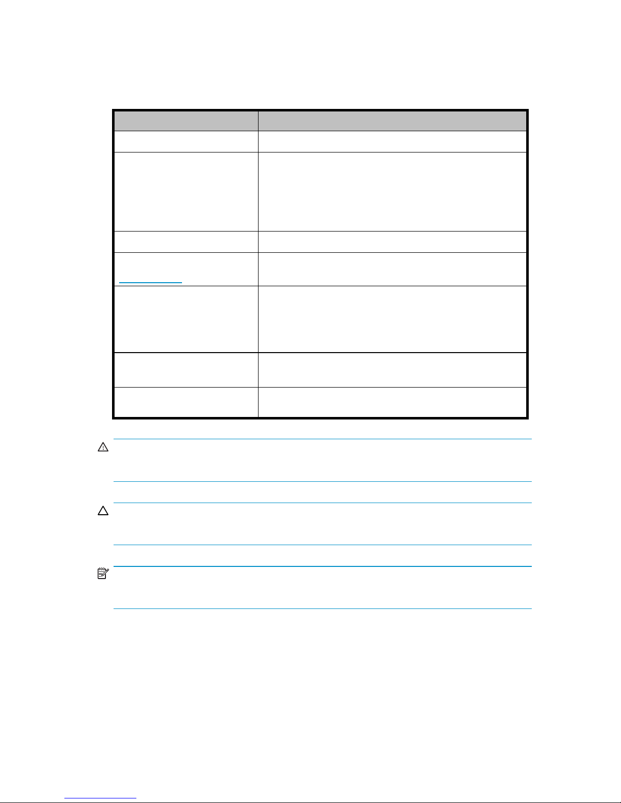
Document conventions and symbols
Convention
Element
Blue text
Cross-reference l
inks and email addresses
Bold
• Keys that are pre
ssed
• Text typed into a GUI element, such as a box
• GUI elements that are clicked or selected, such as
menu and list it
ems, buttons, tabs, and check boxes
• Literal values typed exactly as shown
Italics
Text emphasis and book titles
Blue, underlined:
w
ww.hp.com
Web site addresses
Monospace fo
nt
• File and directory names
• System outp
ut
• Code
• Commands, their arguments, and argument values
Monospace, italic
font
• Code variables
• Command v
ariables
Monospace, bold
font
Emphasized monospace text
WARNING!
Indicates that failure to follow directions could result in bodily harm or death.
CAUTION:
Indicates that failure to follow directions could result in damage to equipment or data.
NOTE:
Provides additional information.
HP StorageWorks XP10000 Disk Array Site Prep Guide
7
Page 8

Rack stability
Rack stability protects personnel and equipment.
WARNING!
To reduce the r
isk of personal injury or damage to equipment:
• Extend leveling jacks to the floor.
• Ensure that the full weight of the rack rests on the leveling jacks.
• Install sta
bilizing feet on the rack.
• In multiple-rack installations, fasten racks together securely.
• Extend only one rack component at a time. Racks can become unstable if more
than one co
mponent is extended.
HP technical support
Telephone numbers for worldwide technical support are listed on the HP support web
site: h
ttp://www.hp.com/support/.
Collect the following information before calling:
• Technical support registration number (if applicable)
• Product serial numbers
• Product model names and numbers
• Error messages
• Operating system type and revision level
• Detailed questions
For continuous quality improvement, calls may be recorded or monitored.
Subscription serv ice
HP strongly recommends that customers register online using the Subscriber’s choice web
site: h
ttp://ww w.hp.com/go/e-updates.
Subscribing to this service provides you with e-mail updates on the latest product
enhancements, newest driver versions, and firmware documentation updates as well as
instant access to numerous other product resources.
After subscribing, locate your products by selecting Business suppor t and then Storage
under Product Category.
8
Preface
Page 9

Other HP web sites
For additional information, see the following HP web sites:
•w
ww.hp.com
•www.hp.com/go/storage
•www.hp.com/service_locator
•www.docs.hp
.com
HP StorageWorks XP10000 Disk Array Site Prep Guide
9
Page 10

10
Preface
Page 11

1 Site prep team and tasks
The objective of a site preparation is to prepare your site for the successful and timely
installation of the HP XP10000 disk array. Proper site preparation is vital for the
reliability of the disk array.
Site prep involves a careful balance of equipment design criteria, site environmental
variables, your business needs, and your budget constraints.
In addition to this guide, other site prep resources may be available to you. The HP
service organization is committed to making sure you receive maximum benefitfromyour
disk array. HP representatives will guide and assist you throughout the site prep process.
HP StorageWorks XP10000 Disk Array Site Prep Guide
11
Page 12

Thesiteprepteam
The site prep team plans, schedules, and completes all tasks necessary to prepare your
site for succ
essful disk array installation.
The site prep team consists of HP representatives and you, the customer.
HP representative responsibilities
The HP team includes various HP representatives who have the training, knowledge,
experience, tools, and parts required to install and maintain XP disk arrays. This team:
• Helps you to determine and implement the site requirements for your specific
site and array configuration
• Coordinates all HP resources to ensure successful delivery and installation of
the disk array
Your HP SR is your primary point of contact with HP during the site preparation process.
Customer responsibilities
As part of
thesiteprepteam,yourresponsibilitiesincludeplanningandpreparing
asuitab
le environment for the disk array, and scheduling equipment delivery and
installation. However, HP representatives are available to help you throughout the site
prep process. Your internal site team may include personnel specializing in your site
comput
er room, such as your storage administrator and your site electrician.
12
Site prep team and tasks
Page 13

Site prep tasks
Contact your HP SR for assistance at any time during the site prep process.
1. If you have not printed a copy of this guide, HP recommends that you print at least
Chapter 2 and the “Site prep checklist”. Working from printed copies makes it
easier to use the tools provided and provides hard copy documents that you can
keep for you
rrecords.
2. Carefully review Chapter 2 to understand the site requirements for the disk array.
If you plan to connect additional external storage to the XP10000, be sure to
take the requirements of that storage into account. See the documentation for the
external
system.
3. Use the information, instructions, and tools in Chapter 2 to determine site
requirements for the specific disk array components you ordered.
4. On the si
te prep checklist, answer ea ch item “Yes” or “No” as it relates to your site.
The checklist includes references to the pages in this guide where you can find
more information on each item.
5. Checklist items that require a “Yes” answer are marked with asterisks (*). If you
answe
r “No” for any of these items, your site does not meet site requirements for the
disk array. Using the information in Chapter 2, correct the site environment so that
you can answer “Yes” for each of these items.
6. When your site meets all site requirements, contact your HP SR to coordinate
del
ivery of the disk array equipment.
7. If you choose to unpack the equipment cartons without HP supervision, follow the
instructions in Chapter 3.
8. Co
ntact the HP SR to schedule disk array installation and configuration.
HP StorageWorks XP10000 Disk Array Site Prep Guide
13
Page 14
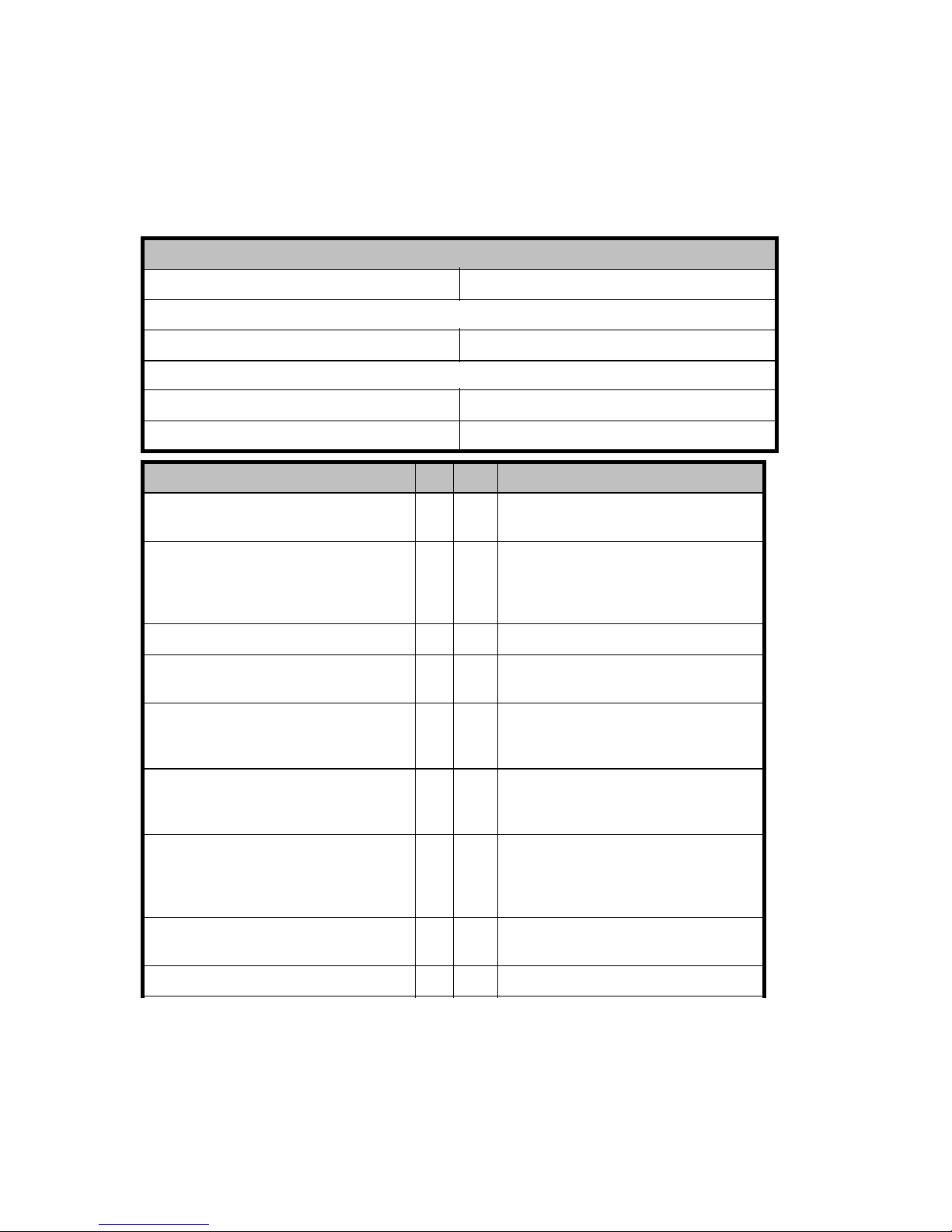
Site prep check
list
Checklist ite
ms that require a “Yes” answer a re marked with asterisks (*). The customer
summary information is included for the benefit of HP representatives, who will help
you complete the checklist.
Customer summary
Customer:
Date:
Address:
Contact:
Phone:
HP summary
HP SR:
Phone:
HP representative:
Phone:
Safety Yes No Reference
Is there a fire protection system in the
computer room?
Fire safety
Isthecomputerroomfreeofany
equipment servicing hazards (for
example, electrical or data cables
that obstruct access)?
Equipment servicing hazards
Is the exi
sting floor plan documented?
The space planning process
Has a new floor plan been developed
to include the new array?
The space planning process
Does the new floor plan include
adequate space for airflow and
servicing needs?
Floor clearance and cutout
dimensions
Does th
enewfloor plan include the
cleara
nce required for the floor’s load
ratin
g?
Floor clearance and cutout
dimensions
Is the computer room structurally
complete (walls, floor, air
conditioning system, and so
on)?
General computer room
requirementsAir conditioning
Is the raised floor adequate for the
equipment load?
Raised floor requirements
Is antistatic flooringormatsinstalled?
Pre
venting electrostatic discharge
14
Site prep team and tasks
Page 15

Are there cutouts or channels for
cable routing?
Floor clearance and cutout
dimensions
Is there a dedicat
ed analog telephone
line for “phone home” configuration?
Data comm requirem
ents
Is a telephone line available for HP
representative use?
Data comm requirements
Is a private LAN available?
Data comm requirements
Can t he temperature be maintained
between 16× and 32× C?
Temperature spe
cifications
Can temperature changes be held to
less than 10× C per hour?
Temperature specifications
Can the humidity level be maintained
between 20% and 80%?
Humidity specifications
Is the compu
ter room protected
against dus
t, pollution, and metallic
particula
te contamination?
Dust and pol
lution controlMetallic
particulat
e contamination
Does the computer room support
other environmental considerations
(such as vibration and acoustics)?
Mechanical vibration
specificationsAcoustics
Are sufficient AC outlets, on different
lines, available for the equipment?
Electrical requirements
Does the
input voltage correspond to
the equipment specifications?
Electri
cal requirements
Are the input circuit breakers
adequate for equipment loads?
Electrical requirements
Does the input frequency correspond
to equipment specifications?
Electrical requirements
Is an appropriate uninterruptible
power supply (UPS) strategy in place?
Uninterruptible power supply (UPS)
If lightning arresters are
recommended, are they installed?
Protection against sources of
electrical interference
Have all sources of electrical
interference been corrected?
Protection against sources of
electrical interference
Doe
s the customer site have
ac
cess control (for example, do HP
re
presentatives need an escort)?
N/A
Does the computer room have
access control (for example, do HP
representatives need a security code)?
N/A
HP StorageWorks XP10000 Disk Array Site Prep Guide
15
Page 16

Are all floors, stairs, elevators,
stairwalkers, lifts, ramps, or ladders
needed to move the equipment
adequate to support its weight and
size?
Dimensions and weights
Will the equipment fitthroughall
doors and corrid
ors and in lifts?
Dimensions and w
eights
Doesthebuildinghavealoading
dock? Maximum access height is
_____m.
Dimensions and weights
Additional equipment N/A
For any additi
onal equipment
required (fo
r example, connectors,
receptacles
,cables,andany
equipment n
ot supplied by HP), is the
equipment o
nsiteandreadyforuse?
N/A
Site prep time allowances
The following site prep tasks may require several weeks:
• Acquiring required power connectors
• Arranging for an electrician
• Adding or modifying air conditioning systems
• Making building alterations
• Placing an order for data comm equipment
The time between placing an equipment order and actual delivery can vary. Contact
your HP representative to determine the best estimated delivery dates.
16
Site prep team and tasks
Page 17

2Siterequirements
Your site must meet the following requirements before HP can deliver and install the
disk array:
• General computer room requirements
• Safety requirements
• Raised floor requirements
• Environmental requirements
• Data comm requirements
• Electrical requirements
• Protection aga inst sources of electrical interference
• Uninterruptible power supply (UPS)
HP StorageWorks XP10000 Disk Array Site Prep Guide
17
Page 18

Disk array physical specifications
Use the information in this section to determine the total dimensions and weight for your
specificarrayconfiguration. You will need these values to complete other procedures
in this chapter.
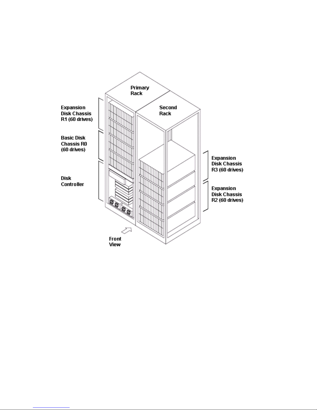
The followin
g figure shows the disk array equipment racks.
Primary rack
In the basic configuration, the disk array consists of one primary 19-inch rack containing
the following:
• One disk con
troller with control panel and SVP blade PC
• One 60-disk chassis, consisting of two 30-drive HDU boxes
• Mix board with disk adapters and host ports
• Power supp
lies, power distribution units (PDUs), backup batteries, power cords,
and cabling
Primary rack expansion
You can exp
and the primary rack as follows:
• Add one 60-disk chassis containing two 30-drive HDU boxes to the top space of
the primary rack. This provides a total of 120 drives.
Second rack
After exp
anding the primary rack, you can add a second 19-inch rack with additional
disk uni
ts as follows:
• Addone60-diskchassistothesecondrackforatotalof180drives
• Add a second 60-disk chassis to the second rack for a total of 240 drives
Disk arr
ay basic storage includes disk chassis R0 in the primary rack. Add more disk
chassi
s in the order shown in the figure: R1, R2, R3.
18 Site requirements
Page 19
HP StorageWorks XP10000 Disk Array Site Prep Guide
19
Page 20

Dimensions and
weights
Use the packaged values when determining delivery space and loading requirements
and unpackaged values during space and floor load planning. In the USA and Canada,
most shipments use a special carrier process in which frames are shipped without
pallets, ramps, or cartons. In these cases, the packaged weight is the unpackaged
weight plus
23 kg (50 lb).
Rack specification
Unpackaged rack Packaged rack
Width 610 mm, 24.0 inches 950 mm, 37.4 inches
Depth 925 mm, 36.4 inches 1110 mm, 43.7 inches
Height 1920 mm, 75.6 inches 2030 mm, 79.9 inches
Weight, p
rimary rack, basic
335.5 kg,
740 lbs
448.5 kg,
989 lbs
Weight, primary rack,
maximum
577 kg, 1272 lbs 690 kg, 1521 lbs
Weight second rack,
maximum
47 3 kg, 1043 lbs 586 kg, 1292 lbs
20 Site requirements
Page 21

Component weig
hts
The following
table provides approximate weights of additional disk array components.
The number of d
isk drives is the m a in factor accounting for total weight of the disk
array. Actua
lweightofthearrayracksistheminimumrackweightplustheweightofall
additional components.
Product
Description
kg lb
AE006A
HP XP12000/100 00 16-port 2-Gb FC CHIP
5.0 11.0
AE007A
HP XP12000/10000 32-Port 2-Gb FC CHIP
5.8 12.8
AE008A
HP XP12000/
10000 FC SFP LW Transceiver
0.02
0.04
AE010A
XP12000/10000 32-port 4 Gbps FC SW
CHIP pair
5.9 13
AE013A
HP XP12000/10000 8-Port FICON SW CHIP
5.7
12.6
AE014A
HP XP12000/
10000 8-Port FICON LW CHIP
5.7
12.6
AE015A
XP12000/10000 16-port 1–2 Gbps FICON
SW CHIP pair
5.9 13
AE016A
XP12000/10000 16-port 1–2 Gbps FICON
LW C HIP pair
5.9 13
AE017A
HP XP12000
/10000 16-Port EXSA CHIP
5.4
11.9
AE018A
HP X P12000/10000 8-Port 1-Gb NAS SW
CHIP
6.5
14.3
AE025A
HP XP12000/10 000 4-GB Cache Memory
0.2
0.44
AE030A
HP XP1200
0/10000 1-GB Shared Memory
0.06 0.13
AE102A
HP XP10000 19" primary rack, disk
controller, base disk chassis for up to 60
HDDs, power supplies, base batteries for up to
12GB cache and up to 3GB Shared M emory
335.5
740
AE104B
HP XP10000 Disk Chassis
80.4
177
AE105B HP XP10
000 16-Port FC SW CHIP 8-Port ACP
5.0 11.0
AE110B
HP XP10000 Battery 8.0 17.6
AE115B
HP XP10000 Second Rack Disk Array Frame DKU
261
575
AE120A
HP XP
10000 73GB 15k rpm Array Group
4.4
9.7
AE120AS
HP XP10000 73GB 15k rpm Spare Disk
1.1
2.4
HP StorageWorks XP10000 Disk Array Site Prep Guide
21
Page 22
Product
Description
kg lb
AE121A
HP XP10000 146GB 10k rpm Array Group
4
8.8
AE121AS
HP XP10000 146GB 10k rpm Spare Dis k
1
2.2
AE122A
HP XP10000 146GB 15k rpm Array Group
4
8.8
AE122AS
HP XP10000 146GB 15k rpm Spare Dis k
1
2.2
AE123B
HP XP10000 300GB
10k rpm Array Group
4
8.8
AE123BS
HP XP10000 300GB 10k rpm Spare Disk
1
2.2
22 Site requirements
Page 23

Calculating the weight of your disk array configuration
The total weight of your array configuration includes the controller, the disk chassis, plus
the total of all disk drives in each cabinet and any optional components. Your site must
have adequate floor strength to suppor t the total weight of the array, from the delivery
area to the co
mputer room.
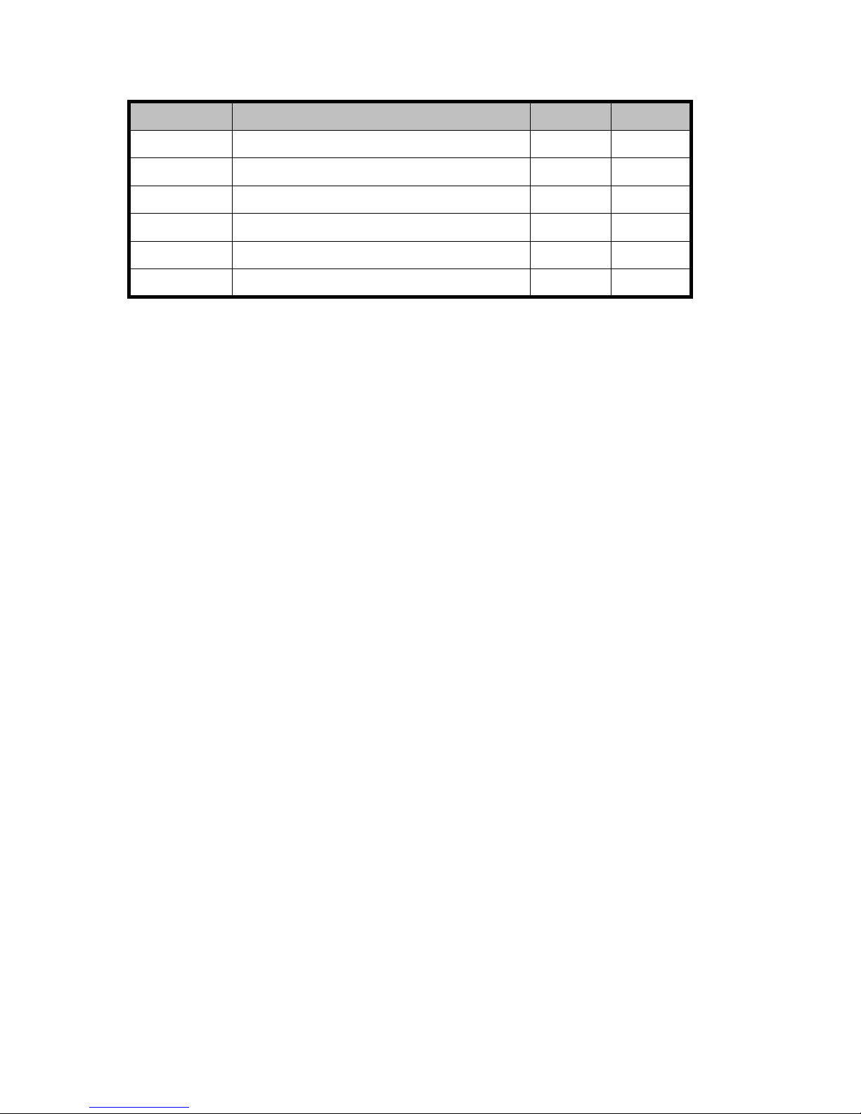
Fill in the following weight calculation worksheet to calculate the total weight of your
unpackaged array configuration, in your preferred units (kg or lb). Following the
worksheet is a completed example worksheet.
Use the calc
ulated total weight to estimate the required floor load rating for the computer
room as explained later in this chapter.
Part Number
Descriptio
n
Weight
Quantity
Total weigh
t
Total weight of your configuration
HP StorageWorks XP10000 Disk Array Site Prep Guide
23
Page 24

Weight calcula
tion example
Part
Number
Description
Weight
Quan-
tity
Total
weight
AE102A
HP XP10000 19" Primary Rack, disk
controller, base disk chassis for up
to 60 HDDs, power supplies, base
batteries for up to 12GB cache and
up to 3GB Shared Memory
740 x
1=
740 .0
AE007A
HP XP12000/10000 32-Port 2-Gb
FC CHIP
12.8 x
1=
12.8
AE025A
HP XP12000/10000 4-GB Cache
Memory
0.44 x
1=
0.4
AE030A
HP X P12 000/10000 1-GB Shared
Memory
0.13 x 3 =
0.4
AE104B
HP XP10 000 Disk Chassis (holds up
to 60 drives)
177.0 x
1=
177.0
AE105B HP XP100
00 16Port FC SW CHIP
8-Port
ACP
11.0 x
1=
11.0
AE110B
HP XP10000 Battery 17.6 x
1=
17.6
AE123B
HP XP10000 300GB 10k rpm Array
Group
8.8 x 28 =
246.4
AE123BS
HP XP1
0000 300GB 10k rpm Spare
Disk
2.2 x 8 = 17 .6
Total unpackaged weight of your configuration (rounded)
1223.2
24
Site requirements
Page 25

Delivery space requirements
The delivery area must provide enough space and floor strength to support the packaged
equipment cartons for the disk array. Refer to the packaged dimensions and weights
under the heading “Dimensions and weights.”
CAUTION:
Make sure tha
t your doorways and hallways provide enough clearance to move the
equipment s
afely from the delivery area to the computer room. Permanent obstructions
such as pillars or narrow doorways can cause equipment damage. If necessary, plan
for the removal of walls or doors.
CAUTION:
Make sure all floors, stairs, and elev ators you use when moving the disk arr ay to the
computer room can support the weight and size of the equipment. Failure to do so
could damage the equipment or your site.
HP StorageWorks XP10000 Disk Array Site Prep Guide
25
Page 26

General computer room requirements
The goal of a computer room is to maintain an ideal environment for computer
equipment, including XP disk arrays.
Make sure your computer room adheres to all national and local building codes for a
data center/computer room environment.
HP recommend
s that you follow these general guidelines:
• Locate the computer room away from exterior walls of the building to avoid the
heat gain from windows and exterior wall surfaces.
• When exterior windows are unavoidable, use windows that are double or tripled
glazed and
shaded to prevent direct sunlight from entering the computer room.
• Maintainthecomputerroomatapositivepressurerelativetothesurrounding
spaces to reduce introduction of contaminants.
• Install a vapor barrier around the entire computer room envelope
(floors/
walls/ceiling) to help keep moisture out of the room. This is especially
import
ant if your computer room is located underground.
• Caulk and vapor-seal all pipes and cables that penetrate the computer room
envelope.
26 Site requirements
Page 27

Preventing ele
ctrostatic discharge
Electrostatic discharge (ESD) can cause component damage, especially during servicing
operations.
Static charge
s occur when objects are separated or rubbed together. The voltage level
of a static ch
arge is determined by the following factors:
• Types of materials
• Relative humidity — low humidity tends to increase ESD voltage.
• Rate of chan
ge — a sta ndard air conditioner cools the air and lowers humidity.
The faster
the air is cooled and dried, the greater the likelihood of ESD.
• Separation — refers to the static discharge that can be generated when two
objects are separated. For example, printer paper is often stored in cool dry
conditions. If opened and used immediately, the act of removing the paper
from its box generates static.
Follow these precautions to minimize possible ESD-induced failures in your co mputer
room:
• Install c onductive flooring(conductiveadhesivemustbeusedwhenlayingtiles).
• Useconductivewaxifwaxedfloors are installed.
• Ensure
that all equipment and flooring are properly grounded and are at the
same ground potential.
• Useconductivetablesandchairs.
• Store
spare electric parts in antistatic containers.
• Use proper cooling equipment to reduce the risk of ESD by maintaining
recommended humidity level and airflow rates.
• Leave boxes of paper open in the computer room for several hours before use to
all
ow static to discharge gradually over time.
HP StorageWorks XP10000 Disk Array Site Prep Guide
27
Page 28

Safety requirements
When making decisions concerning site safety, your first concern should be the safety of
your personnel and then the safety of your equipment.
Fundamental safeguards for disk arrays should include a site well away from any
sources of potential damage.
If you have any qu estions on site safety, consult your HP representative, your insurance
carrier, an
d local building inspectors for safety recommendations.
Fire safety
Consult your insurance carrier and local fire department for fire safety suggestions. They
can analyze your existing fire control systems and advise you on any required changes.
If you are building a new site or making structural changes to an existing site, consult
your local b uild ing cod es for fire prevention and protection guidelines.
Equipment servicing hazards
Your staff and HP service personnel require safe access to the disk array. Running
electrical and data communication cables underneath your computer room’s raised floor
is the b
est way to ensure that they do not create a safety hazard.
Electrical hazards
The disk array equipment racks contain dangerous voltages. To prevent injury or death
from electric shock, refer all electrical installation and service to qualified personnel.
28 Site requirements
Page 29

Space planning requirements
Space planning involves making sure that your computer room:
• Is large enou
gh to hold the new array and other equipment and furniture
• Provides clearance around the array for service access and to ensure proper
weight distribution on the computer room’s floor
• Includes cor
rectly positioned floor cutouts for the array’s power and data c ables
The space planning process
1. Document your computer room’s existing floor plan, including locations of these
items:
a. Im movable objects, such as structural support columns
b. Walls
c. All equipment, furniture, cabinets, racks, data comm equipment, and systems
d. Floor cutouts
e. Electrical outlets
f. Interconnecting cables and power cords, including lengths
g. Floor vents
2. Developanewfloor plan that includes the locations of all of the above items
plus the disk array and any new items added to support it. Include flexibility to
accommodate additional equipment as your requirements increase.
3. Implem ent the new floor plan, leaving empty space where the array will be
installed. If the new floor plan requires construction changes, consult with local
contractors and your HP representatives.
HP StorageWorks XP10000 Disk Array Site Prep Guide
29
Page 30

Raised floor requirements
The computer room floor must be able to support the total weight of the equipment as
well as localized weight at each caster or foot of the equipment cabinets. A common
method of preparing an adequate floor for a computer room is to construct a raised
flooroverthebuildingfloor. A raised floor:
• Allows weight to be spread evenly across the floor
• Provides a
nunder-floor area for running interconnecting cables conveniently
and unobtrusively
• Allows optimum distribution of conditioned air
WARNING!
If metal is used in the construction of the raised floor, ensure that there is a common
ground co
nnection between the raised floor and main floor to avoid possible build
up of dif
ferent voltage potentials. Failure to comply can result in serious injury to
personnel and damage to equipment.
Requirements for raised floors:
• Raised floor access ramps must not exceed a 10 degree slope.
• Use a raised floorsystem(254to305mm,10to12inches)forthemost
favorable room air distribution system.
• Gridpanelsmustbeatleast450x450mm(17.72x17.72in).
• The floor must have a load rating between 300 and 500 kg per square meter
(553 to 921.7 lb per square yard, or 61.4 to 102.4 lb per square foot). The
maximum floor loading at any point is 500 kg (1102.3 lb) .
30 Site requirements
Page 31

Estimating required floor load rating
To estimate the load rating you need for your floor, consider the total weight of all
of these items:
• Thediskarray;seetheprecedingComponent weights
• Other equipm
ent
• Furniture such as desks, chairs, and storage cabinets
• Computer room personnel
• Moving equi
pment such as forklifts, dollies, and similar items
The lower t
he floor load rating, the more clearance is required around the array to
distribut
e the equipment weight correctly. If your computer room is too small to allow
for minim
um required clearance around the array, you may need to increase the floor
load rating. For more on required clearance, see Floor clearance and cutout dimensions
later in this chapter.
Floor covering
HP recommends the use of a tiled raised floor.
CAUTION:
HP strongly discourages the use of carpeting, including antistatic varieties, within 6.0 m
(20 ft.) of the disk array. Over time, carpeting may shed dust that can cause problems
with the disk array.
CAUTION:
If your computer room has carpeting, place static discharge mats so that personnel
must walk across them before touching any part of the array. Failure to comply with this
precaution can result in equipment damage through static discharge.
HP StorageWorks XP10000 Disk Array Site Prep Guide
31
Page 32

Floor clearanc
e and cutout dimensions
Figures on the following pages show the clearance dimensions, locations of floor cutouts,
and other dimensions for the primary and second racks.
Primary rack dimensions and c able cutout location
The following figure shows rack dimensions, clearances, and the cable cutout location.
The cutout may be off-center as long as it is within the area shown and corresponds
to the opening in the bottom of the cabinet to allow cables to pass through. See the
following pages for additional notes.
32 Site requirements
Page 33

Calculating cl
earances
The total floor c
learance required for the disk array includes:
• The actual space required by the equipment.
• Service clearance — the floor space required to access the disk array. Never
use this space
for storage.
• Additional space required to properly distribute the equipment weight on your
computer room’s raised floor. The amount of additional space required depends
on your floor load rating.
HP StorageWorks XP10000 Disk Array Site Prep Guide
33
Page 34

34
Site requirements
Page 35

Calculate primary rack clearance dimensions as follows:
• Clearance “a” is the space between the service clearance at the left side of
the array (100 mm minimum for installing the kickplate) and any other object,
such as a desk or wall.
• Clearance “b” is the space between the service clearance at the right side of the
array (100 mm for the kickplate) and any other object.
• Clearance “c” is the space between the service clearance at the front of the
array and any other object.
• Usethevalueof“c”andyourfloor load rating to determine the values for a
and b according to the following steps.
1. Determine how much space you can assign to clearance “c”. For maintenance
purposes, try to make “c” larger (1000 mm) rather than smaller (0 cm). The
smaller “c” is, the larger “a” and “b” must b e.
2. In the following floor loading table, findthecolumnfor“c”thatmostclosely
matches your value. If your “c” value is in between two table values, use the
larger table value. Then, find the row for your floor load rating. Where the
column and row intersect is the a+b value.
3. To determine clearance “a” and clearance “b”, divide the a+b value between
“a” and “b”. They do not need to be equal. For example, if the a +b value
from the table is 600 mm, then “a” can be 400 mm and “b” can be 200, or
both “a” and “b” can be 300.
4. Calculate clearances by filling in and adding the table columns below:
Left
(add down)
Right
(add down)
Front
(add down)
Back
(add down)
Clearance
values
a _________
b _________
c _________
Not applicable
Plus minimum
service
clearance
100 mm (3.94
in)
100 mm (3.94
in)
1000 mm (39.4
in)
1000 mm (39.4
in)
Equal
stotal
clea
rance
HP StorageWorks XP10000 Disk Array Site Prep Guide
35
Page 36

Primary rack cl
earance notes and floor loading
The following n
otes apply to preceding primary rack dimensional figures.
Note *1: Cleara
nce (a+b) depends on the floor load rating and clearance “c”. Required
clearances fo
rvariousfloor load ratings are shown below.
Required clearance (a + b) mm
Clearance (c) mm
Floorload
rating
(kg/mm2)
c = 0 c = 200 c = 400 c = 600 c = 1000
500 200 100 0.00 0.00 0.00
450
300 200 100 100 0.00
400 400
300 300 200 100
350 600 500
400 400
200
300 1000 800 700 600 500
Provide100mmofclearanceonbothsidesofthediskarraywhenthekickplatesareto
be attache
d after the disk array is installed. When disk arrays of the same type are to
be installed adjacent to each other, clearance between the arrays may be 100 mm.
Additional notes on primary rack floor loading and clearances:
• Decide actual clearances in consultation with the construction specialist
responsible for installation. They may vary depending on the size and layout of
the system and building conditions.
• When multiple disk arrays are arranged in a row, base your clearance values on
the requirements of the largest disk array.
• Generally, clearances (“c”) should be as large as allowable.
36 Site requirements
Page 37

Primary and sec
ond rack clearance dimensions and cutouts
The following fi
gures show floor clearance dimensions when two racks are installed.
See also the ta
ble and text following the figures for notes and details. Clearances
for two racks
are calculated and recorded in the preceding table in the same way as
asinglerack.
HP StorageWorks XP10000 Disk Array Site Prep Guide
37
Page 38

38 Site requirements
Page 39

Primary and sec
ond rack clearance notes and floor loading
The following e
xplanatory notes apply to the preceding floor clearance drawings for the
primary and second rack.
*1: Clearance (a+b) depends on the floor load rating and clearance “c”. Required
clearances for various floor load ratings are shown below.
*2: Clearance between racks must be at least 10 mm. If the kickplate is installed after
rack placeme
nt, allow 100 mm.
Required clearance ( a + b) mm
Clearance (c) mm
Floorload
rating
(kg/mm2)
c = 0 c = 200 c = 400 c = 600 c = 1000
500 100 0.00 0.00 0.00 0.00
450
300 200 0.00 0.00 0.00
400
600
400
300 200 0.00
3501000800600500200
300 1600 1300 1100 900 600
Addition
al primary and second rack floor loading and clearance notes:
• Decide actual clearances in consultation with the construction specialist
responsi
ble for installation. They may vary depending on the size and layout of
the system and building conditions.
• When multiple disk arrays are arranged in a row, b ase your clearance values on
the requirements of the largest disk array.
• Genera
lly, clearances (“c”) should be as large as allowable.
HP StorageWorks XP10000 Disk Array Site Prep Guide
39
Page 40

Environmental requirements
The environmental specifications for operating your dis k array must be satisfied before
installation.
Altitude
The maximum altitude for disk array operation is 3,000 meters. For nonoperational or
storage situations, the maximum altitude is 4,000 m eters.
Air conditioning
Use separate computer room air conditioning duct work. If it is not separate from the
rest of the building, it might be difficult to control cooling and air pressure levels. Duct
work seals are important for maintaining a balanced air conditioning system and high
static air pressure. Adequate cooling capacity means little if humidity levels increase
when the ducts are exposed to warm air, producing condensation. Condensation on
any disk
hardware can damage the components.
Any ques
tions regarding the adequacy of airflow construction should be referred to and
evalua
ted by a qualified structural engineer.
40
Site requirements
Page 41

Temperature specifications
Temperature range type Range
Recommended operating temperature range 21 to 24 degrees C
70 to 75 degrees F
Operating tem
perature
16 to 32 degree
sC
61 to 89 degree
sF
Nonoperating temperature range
–10 to +43 degrees C
14 to 109 degrees F
Shipping and storage temperature (product
packed in factory packing)
–25 to +60 degrees C
–13to+140degreesF
Temperatur
e shock immunity (maximum rate
of temperat
ure change)
10 degrees C
per hour
18 degrees F
per hour
HP StorageWorks XP10000 Disk Array Site Prep Guide
41
Page 42

Humidity specifications
Maintain proper humidity levels. High humidity levels cause galvanic actions to occur
between some dissimilar metals. This eventually causes a high resistance between
connections, leading to equipment failure.
Low humidity contributes to undesirably high levels of electrostatic charges. This
increases th
e electrostatic discharge (ESD) voltage potential. ESD can cause component
damage during servicing operations.
Low humidity levels are often the result of the facility heating system a nd occur during
the cold season. Most heating systems provide air with a low humidity level, unless the
system has a built-in humidifier.
You shou ld
not see any condensation in or around the disk array under any conditions.
There is no procedure for recovery from moisture condensation.
Humidity r
ange type
Nonconden
sing relative humid it y (RH)
Operating humidity range at 22 d e grees C
(71 degrees F)
20%to80%
Nonoperating humidity range
8% to 90%
Shipping and storage humidity range
(produ
ct packed in factory packing)
5% to 95%
Operating maximum wet bulb temperature 26 degrees C
79 degrees F
Nonoperating maximum wet bulb
temperature
27 degrees C
81 degrees F
Shipping and storage maximum wet bulb
temperature
29 degrees C
84 degrees F
42
Site requirements
Page 43

Mechanical vibration specifications
Continuous vi
bration can cause a slow degradation of mechanical parts and, when
severe, can cause data errors in disk drives. Mechanical connections such as printed
circuit assembly (PCA) conductors, cable connectors, and processor backplane wiring
can also be affected by vibrations. Vibration specifications apply to all three axes. For
vibration te
sting methods, see ASTM D999-91 Standard Methods for Vibration Testing
of Shipping
Containers.
Condition
Specification
Operating 0.25 mm, 5–10 Hz
0.05 G, 10–300 Hz
Nonoperating
2.5 mm, 5–10 Hz
0.5 G, 10–70 Hz
0.05 mm, 70–99 Hz
1.0 G, 99–300 Hz
Shipping and storage (product packed in
factory packing)
0.5G,15minutes(atfourmostsevere
resonances between 5–200 Hz)
Shock specifications
The following tables lists shock specifications. For horizontal shock testing methods,
see ASTM D5277-92 Standard Test Methods for Performing Programmed Horizontal
Impacts Using an Inclined Impact Tester. For vertical shock testing methods, see ASTM
D6055-96 Standard Test Methods for Mechanical H andling of Unitized Loads and
Large Shipping Cases and Crates.
Condition
Specification
Operat
ing
None
Nonoperating
8G,15ms
Shipping and storage (product packed in
factory packing)
Horizontal: Incline impact: 1.22 m/s
Vertical: Rotational edge: 0.1 m
HP StorageWorks XP10000 Disk Array Site Prep Guide
43
Page 44

Heat dissipation, power consumption, and air flow
The following table describes the heat dissipation and power consumption of the
XP10000 when loaded with the maximum number of disk drives.
Parameter
Primary Rack Second Rack Full array
Power consumption
(kVA)
4.
9
3.2 8.1
Heat dissipation
(kW)
4.6
3.0 7.6
BTUs per hour
15710 10246 25955
Kcal per ho
ur
39
59 2582 6541
Thetablebelowshowstheairflow requirements for the frames and disk chassis.
Product
No.
Description
Air flow
(cubic meters
per minute)
AE102A
HP X P1 0000 Disk Control Frame - DKC 15
AE104B
HP XP100
00 Disk Chassis
8
AE115B HP XP10000 Disk Array Frame 8
44
Site requirements
Page 45

The following table presents the power requirements and heat dissipation of individual
components.
Product
No.
Description
Heat output
(kW)
Power
consumption
(kVA)
AE102A
HP XP10000 Disk Control Frame - DKC 0.738 0.761
AE105B
HP XP10000 16Port FC SW CHIP
8-Port ACP 0.370 0.381
AE006A
HP XP12000 /1000
0 16-port 2-Gb FC
CHIP
0.287 0.296
AE007A
HP XP120 00/10000 32-Port 2-Gb FC
CHIP
0.382
0.394
AE010A
HP XP120 00/10000 32-Port 4-Gb FC
CHIP
0.382
0.394
AE013A
HP XP12000/10
000 8-Port FICON
SW CHIP
0.346
0.356
AE014A
HP XP12000/10000 8-Port FICON
LW CHIP
0.346
0.356
AE015A
HP XP12000/10000 1 6-Port FICON
SW CHIP
0.35 0.361
AE016A
HP XP12000/
10000 16-Port FICON
LW CHIP
0.35 0.361
AE017A
HP XP12000/10000 16-Port EXSA
CHIP
0.313 0.323
AE018A
HP XP12000/10 000 8-Port 1-Gb NAS
SW CHIP
0.446 0.46
AE025A
HP XP12000
/10000 4-GB Cache
Memory
0.014 0.014
AE030A
HP XP12000/10000 1-GB Shared
Memory
0.011 0.012
AE110B HP XP10000 Battery 0.044 0.045
AE104B
HP XP10000 Disk Chassis
0.100 0.103
AE115B HP XP10000 Disk Array Frame 0.100 0.103
AE120A
HP XP10000 73GB 15k rpm Array
Group
0.088 0.096
AE121
A
HP XP10
000 146GB 10k rpm Array
Group
0.092 0.1
HP StorageWorks XP10000 Disk Array Site Prep Guide
45
Page 46

Product
No.
Description
Heat output
(kW)
Power
consumption
(kVA)
AE122A
HP XP10000 146GB 15k rpm Array
Group
0.092 0.1
AE123B
HP XP10000 300GB 10k rpm Array
Group
0.092 0.1
AE120AS
HP XP10000 73GB 1
5k rpm Spare
Disk
0.022
0.024
AE121AS
HP XP10000 146GB 10k rpm Spare
Disk
0.023 0.025
AE122AS
HP XP10000 146GB 15k rpm Spare
Disk
0.023 0.025
AE123BS
HP XP10000 300GB 10k rpm Spare
Disk
0.023 0.025
Acoustics
The acoustic emission specification for the disk array is:
• 65 dB (A) so
und pressure, operator position (1 meter from the floor and surface
of the cabinet)
You can reduce the ambient noise level caused by equipment and air conditioning
blowers i
n your computer room by:
• Installing a dropped ceiling covered in commercial-grade, fire-resistant,
acoustic-rated, fiberglass ceiling tile
• Covering the walls in sound-deadening material
• Instal
ling foam rubber removable partitions
46
Site requirements
Page 47

Dust and pollut
ion control
Airborne contaminants and particles of a certain size and hardness can damage the
disk array. Some of the most common contaminants are dust, smoke, ash, eraser debris,
food crumbs, a
nd salty air.
Mechanical filters on the disk array protect it by trapping large dust particles. Smaller
particles can pass through some filters, and can eventually cause problems in mechanical
parts. Prevent sm all dust particles from entering the computer room by maintaining its
air conditioning system at a high static air p ressure level.
Your HP representative can help you determine if you need to be concerned about
airborne c
ontaminants.
Metallic particulate contamination
Metallic particulates can be especially harmful a round electronic equipment. This type
of contamination may enter the data center environment from a variety of sources,
including but not limited to raised floor tiles, worn air conditioning parts, heating
ducts, rotor brushes in vacuum cleaners, or printer component wear. Because metallic
particulates conduct electricity, they have an increased potential for creating short
circuits in electronic equipment.
Over time, very fine whiskers of pure metal can form on electroplated zinc, cadmium, or
tin surfaces. If these whiskers are disturbed, they m ay break off and become airborne,
possibly causing failures or operational interruptions. For over 50 years, the electronics
industry has been aware of the relatively rare but possible threat posed by metallic
particulate contamination. During recent years, a growing concern has developed in
computer rooms where these conductive contaminants are formed on the bottom of
some raised floor tiles.
Although this problem is relatively rare, it may be an issue within your computer room.
Since metallic contamination can cause permanent or intermittent failures on your
electronic equipment, HP strongly recommends that your site be evaluated for m etallic
particulate contamination before installation of electronic equipment.
HP StorageWorks XP10000 Disk Array Site Prep Guide
47
Page 48

Data comm requirements
Route data comm cables away from areas of high static electrical fields created by
power transformers and heavy foot traffic. Use shielded data comm cables that meet
approved industry standards to reduce the effects of external fields.
For the XP disk
array, you need:
Item
Description
A dedicated analog
phone line
Needed for the HP StorageWorks Continuous Track XP “phone
home” feature, if you plan to use it. An HP representative will
configure Continuous Track XP during installation. For more
information on Continuous Track XP, see the HP StorageWorks
XP10000 Disk Array Owner’s Guide.
A twisted pair (Cat 5)
cableAn available LAN
drop on your Intranet
Needed to connect the XP10000 to an available Ethernet
port on your p ublic LAN. To ensure network security, consult
with an HP representative and your network administrator
before selecting the appropriate location of your LAN drop.
Apublicvoicephoneline
near the disk array
Needed to allow your staff and HP representatives to
communicateinsideandoutsideyoursite.
48
Site requirements
Page 49

Electrical requirements
Line voltage
Linevoltage(AC)atthewallpoweroutletisafunctionofthelocalpowerutilityandyour
building power distribution network. Voltages outside of the operating range of the disk
array can cause intermittent system errors or a complete system shutdown. If required,
an HP representative and your electrician can determine the current line voltage and
make recommendations. See "
Chapter 3 Electrical specifications" for specificACline
voltage requirements.
Avoid the use of a line voltage conditioner.
Make sure that a power distribution unit (if used) provides the c orrect voltage to support
your entire system.
Branch circuit breakers
See "Chapter 3 Electrical specifications" for specific branch circuit requirements for
your pow
er situation.
Single-phase branch circuit breakers
The power cords supplied are specified for connection to a single-phase, 20-amp circuit.
Frequency
Usuall
y, AC line frequency is determined by your local power providers. In some cases,
electrical power is supplied by generators. Shifts in AC line frequency can cause system
errors. An HP representative can monitor the frequency of the input AC line power and
make recommendations, if necessary. The disk array requires that the line frequency be
withi
n 0.5 Hz of the rated line frequency (50 Hz or 60 Hz). See "
Chapter 3 Electrical
specifications" for more information.
Safety and dedicated ground
The primary reason for grounding electrical systems is safety. The safety ground is
required by the National Electric Code (USA) and most other local, regional, and
national codes. In addition to safety ground, HP requires that a dedicated (earth
reference) ground be installed as a common reference point for all system components.
Consult with an HP representative and your electrician to ensure that your electrical
system meets all lo cal and national safety codes.
HP StorageWorks XP10000 Disk Array Site Prep Guide
49
Page 50

Grounding requirements
Your site’s electrical subsystem must meet all of the following co nditions:
• Grounding as presc
ribed by your local country codes.
• An insulated grounding conductor that is identical in size and insulation material
and thickness to the ungrounded branch-circuit supply conductors. It should be
green, with or without yellow stripes, and is to be installed as a part of the
branch circuit t
hat supplies the unit or system. This means the ground conductor
must be run in the same conduit, armored cable, or other cable bundle as the
phase wires.
• The grounding c
onductor should be grounded to earth at the service equipment
or other accep
table building earth ground such as the building frames (in case
of a high-rise
steel-frame structure).
• IT-configured grounding systems are not certified for use with the disk array as
these grounding systems may not h ave solidly conductor-connected grounded
power systems and/or they may have resistive imp e dance inserted in ground
and/or neutral lines. The disk array requires a solidly conductor-connected
ground and
may require a separate neutral in the case of WYE or STAR
connectio
ns. For HP disk arrays, TN grounding systems are preferred.
AC connections
The disk array primary rack has four sepa rate connections to 200 VAC, single-phase,
20-amp power.
The second rack has two connections to AC power in the minimum configuration (four
recommended) and four connections to AC power in the maximum configuration. Power
requirements are 200 VAC, single-phase, 20-Amps.
When receptacles are used to connect disk array components to AC power, they must
include a dedicated ground connection that is insulated from the receptacle. It is
important that the receptacle box be g rounded with an additional ground connection
that is separate from the dedicated ground. The additional ground can be hard conduit.
Specific AC power cords and plugs are available to suit the power requirements and
receptacles in your location. You can specify the cords and plugs you need when you
order the HP XP10000 disk array. You are responsible for having the correct plugs and
receptacles installed by an electrician in compliance with local electrical requirements
and practices.
50 Site requirements
Page 51

CAUTION:
When installing the receptacles, the electrician must ensure that each receptacle has its
own neutral (if required) and ground. Using the same neutral/ground for more than one
circuit causes voltage loss and heat problems and can create a fi re hazard. A shared
neutral conductor that fails open-circuit can cause overvoltage damage to equipment.
See "Chapter 3 Ele ctrical specifications" for specific power requirements as well as plug
and receptacle pa rt numbers and ordering information.
Power line transients
Heavy electrical loads from nearby machinery or e quipment (for example, elevators or
electric welders) can cause intermittent system problems with sophisticated electronic
equipment, even if that equipment is on a separate circuit breaker. When faced with
these conditions, provide a separate, completely independent power panel with an
isolated ground an d circuit breaker coming directly from the main building power source
or secondary power source.
If necessary, an HP representative can measure your power line noise level and ma ke
appropriate recommendations concerning the use of line treatment devices.
Protection against sources of electrical interference
Protect the disk array from sources of electrical interference:
HP StorageWorks XP10000 Disk Array Site Prep Guide
51
Page 52

Potential source
Description
Wall outlets
Convenience power outlets for building maintenance equipment
(such as vacuum cleaners and floor buffers) must be wired from circuit
breakers on a power panel separate from the computer system panel.
The ground wires from these outlets must be connected to the normal
building distribution panel and not to the system ground.If a separate
power source and separate ground are not provided, operation of
janitorial equipment can induce electrical noise and cause abnormal
operation of the computer system. Your electrician can verify whether
maintenance outlets are on separate panels.
Lightning In geographical areas subject to lightning storms, it may by advisable
to install l
ightning protection for both personnel and computer
systems. The principles of lightning protection and personnel safety
areoutlinedindetailinthelightningprotectioncodecontainedinthe
National Fire Protection Association (NFPA) Handbook.
Electromagnetic
interference
The disk array is specifically d esigned to reduce its susceptibility to
radiated and conducted interference. Electromagnetic interference
can cause a variety of system problems. An HP representative can
advise you about the most common causes of electromagnetic
interference.
Uninterruptible power supply (UPS)
Most disk array units are installed in data centers where a UPS strategy is already in
place. However, if you are making your first large disk array purchase, you may need
a separate UPS solution.
CAUTION:
If you are planning or already have a site-wide UPS, HP recommends against using a
product UPS powered by a site-wide UPS for the XP10000.
Make sure your UPS satisfies the power requirements listed u n der Heat dissipation
and power consumption in this chapter and also under AC line voltage requirements
in Chapter 3.
52 Site requirements
Page 53

3Electricalspecifications
The detailed electrical specifications in this chapter are provided to help your site
electrician perform any necessary electrical work related to site prep.
AC line voltage r
equirements
The AC power requ
irements are essentially the same for both the primary and the
second racks. Each rack operates on 200 VAC nominal, 20 amps, 50 or 60 Hz,
single-phase power. An independent branch circuit and circuit breaker is required
for each AC input power cord.
The following
table lists specific power requirements.
Parameter
200
VAC
208
VAC
220
VAC
230
VAC
240
VAC
Minimum operating voltage
(VAC)
184
191 202 212 221
Maximum operating voltage
(VAC)
212 220 233
244 254
Rated line current per power
cord
16A 16A 16A 16A 16A
Number of power cords
44444
Recommended circuit breakers
20A 20A 20A 20A 20A
Number of c
ircuit breakers
44444
Important notes:
208 VAC is
60 Hz only. Rated line current per power cord is the maximum allowable
current under worst case conditions. This value applies to each individual power cord
and is specified in RMS amperes. For the second rack, four power cords and circuit
breaker
s are strongly recommended even though a minimum configuration containing
only one
expansion disk chassis requires only 2 power cords and 2 circuit breakers. If
a second expansion disk chassis is added to the second rack, four power cords and
four circuit breakers are required.
HP StorageWorks XP10000 Disk Array Site Prep Guide
53
Page 54

AC inputs
The disk array
primary rack has four separate connections to 200 VAC, single-phase,
20-amp power
. The AC power inputs to the primary rack are distributed to four power
distribution units (PDUs) as shown in the following figure. This provides fault tolerant
operation of the disk array. Each pair of AC inputs (00/10 and 01/11) must be
capable of supporting the entire current demand for the cabinet. Each PDU is fitted with
an IEC320-C20 inlet that fits the supplied input power cord, and four IEC320-C13
outlets th
at connect to the hardware inside the rack by means of supplied cables.
CAUTION:
The four PDU outputs shown in the figures a re for internal power connections to the
disk array only. Do not connect any other equipment to these outlets. Usin g the outlets
for any equipment other than the disk array may compromise disk array reliability
or availability .
Thesecondrackshowninthefollowingfigure has four connections to AC power. Power
requirements are 200 VAC, single-phase, 20-Amps.
54
Electrical specifications
Page 55

HP offers the following AC power cables and connectors, which you can order
individually (four each are required per primary or second rack):
• E7805A HP 4.5 m power cord w/NEMA L6-30P plug
• E7806A HP
4.5 m power cord with stripped ends
• E7808A HP 2 40 V power cord w/ IEC 309 plug, 4.5 m
• E7809A HP 240 V power cord w/ CEE7/7, 4.5 m
• E7810A H
P power cord for China
• E7811A HP power cord for Israel
• E7804A HP power cord, 4.5 m, C19/C20 Plug (jumper for UPS)
• E7798A
cord w/IEC 320-C20 connector and 2.5 m jumper for UPS
You can supply your own power cables as long as they meet a 20 amp rating, fitthe
IEC320-C20 PDU inlets, and me et lo cal codes.
HP StorageWorks XP10000 Disk Array Site Prep Guide
55
Page 56

NorthAmericanACpowercabling
The XP10000 racks each require 20-amp, single-phase 200 VAC power supplied by
four power cords with p lugs, four receptacles, and four main disconnect devices (circuit
breakers). If the second rack contains only one disk chassis, only two power cords and
breakers ar
e required, but four are required if you plan to add another disk chassis.
The XP10000 comes from the HP factory with the AC power cords and plugs you have
ordered. Plug types rated for 30 Amps are specified under the heading, AC inputs
earlier in this chapter. The opposite end of the power cord connects to the XP10000
power distribution unit input, which is a type IEC320 C20 connector.
Connect ea
ch AC power cable to a separate receptacle on a separate circuit breaker,
and connect each pair of power cords (the left pair and the right pair) to separate
distribution panels to ensure power fault tolerance.
CAUTION:
Do not apply power until instructed to do so by HP. An HP representative should be
present
whenever the disk array is being connected to a new power source.
Branch circuit requirements
To protect the disk array, your building must be wired correctly. Each supply ( “hot”)
conductor must be protected by a short-circuit protective device and by an overcurrent
protective device. The table listed under AC line voltage requirements provides
specifications for the overcurrent protective devices required for single-phase operation.
All protective devices must comply with national standards of the country where the
units are to be installed. If a protective device interrupts any supply conductor, it must
also interrupt all other supply conductors.
56
Electrical specifications
Page 57

European AC power cabling
The XP10000 racks each require 20-amp, single-phase 200 VAC power supplied by
four power cords with plugs, four receptacles, and four main disconnect devices (circuit
breakers). If the second rack contains only one disk chassis, only two power cords
and breaker
s are required, but four are recommended if you plan to add another disk
chassis later.
The XP10000 comes from the H P factory with the AC power cables and plugs or
stripped ends you have ordered. Plug types are specified under the heading, AC inputs.
The opposite end of the power cord connects to the XP10000 power distribution unit
(PDU) inp
ut, which is a type IEC 320-C20 connector.
European branch circuit requirements
To protect the disk array, your building must be wired correctly. Each supply (“hot”)
conductor must be protected by a short-circuit protective device and by an overcurrent
protective device. The table listed under AC line voltage requirements provides
specifications for the overcurrent protective devices required for single-phase operation.
All protective devices must comply with national standards of the country where the
units are to be installed. If a protective device interrupts any supply conductor, it must
also interrupt all other supply conductors.
Overcurrent protection is also required for the neutral conductor.
Your electrician should know the appropriate code requirements for your location/site
and wire power distribution to the XP10000 accordingly.
HP StorageWorks XP10000 Disk Array Site Prep Guide
57
Page 58

Connecting the
European power-supply cables
Connect each AC power cable to a separate receptacle on a separate circuit breaker,
and connect each pair of power cords (the left pair and the right pair) to separate
distribution panels to ensure power fault tolerance. Sing l e-phase power cable wiring is
showninthefigure below.
CAUTION:
Do not apply
power until instructed to do so by HP. An HP representative should be
present whenever the disk array is being connected to a new power source.
CAUTION:
Be sure to connect the power cords to the distribution panel as shown in the figure.
Improper wiring of the neutral conductor may cause damage to the disk array. To
reduce the risk of a wrong connection, use a plug and socket that are approved for
this disk array. It is your electrician’s responsibility to select and install the proper
plugs and receptacles.
WARNING!
High leakage current can occur between the power supply and the unit. To avoid
electrical shock, be sure to make the protecti ve earth connection before the supply
connections.
58
Electrical specifications
Page 59

4 Delivery and un packin g
The disk array equipment is shipped directly from HP. If the disk array is part of a system
order, HP coordinates shipment from all HP locations so that all of the equipment arrives
at your site at approximately the same time.
When your equipment ships, HP p rovides you with carrier information and an expected
delivery date. Factors beyond HP’s control can cause delivery delays. If you have not
received your equipm ent within two weeks of its shipment from HP, contact your HP SR,
who will trace your order and expedite delivery.
CAUTION:
Before delivery, make sure your site meets the requirements explained under the
heading, “Delivery space requirements”.
HP StorageWorks XP10000 Disk Array Site Prep Guide
59
Page 60

Checking for shipping shortage and damage
Upon delivery of each equipment shipment:
1. Check the carrier’s bill of lading to ensure that the items listed match the item s
delivered. Notify the carrier immediately if there are any discrepancies or missing
items.
2. Inspect all shipping containers for signs of damage, such as dents, scratches, cuts,
or water ma rks.
3. If you see an
y damage to the containers:
a. Note on the bill of lading that there is apparent damage, subject to inspection.
b. Arrange for the carrier’s representative and an HP representative to be present
when the item in question is unpacked.
c. Contact y
our HP representative, who will make sure any damaged components
are repl
aced, regardless of the circumstances and without waiting for any
claim settlements.
Unpacking the equipment
HP representatives will supervise the unpacking and moving of the disk array equipment.
It is your responsibility to provide the people, tools, and equipment necessary to perform
these tasks.
Requi
red personnel
HP re
commends that three physically able personnel be available to assist with
off-loading the disk array equipment from the pallet. Personnel must be knowledgeable
and experienced with the safe handling of large, heavy, and sensitive computer
equipment.
Required tools
• Claw hammer (if full packaging with wooden crate)
• Ratchet wrench or box-open end wrench sizes 11mm (7/16") and 19mm (3/4"),
or adjustable end wrench
• 6mm hex wrench
• Scissors or box knife to cut polyester banding
• Safety glasses
• Short stepladder (helpful, but not required)
60
Delivery and unpacking
Page 61

Packaging configurations
XP disk array cabinets are shipped in one of three standard packaging configurations:
• Environmental pack — consists of stretch wrap over corner protectors. No
special tools
or procedures are required to unpack shipments in this form. This
packaging is used for most shipments within the USA and Canada that are direct
from the factory to the customer. HP uses special carriers with a de dicated fleet
of trucks and specially trained personnel.
• Full packag
ing — consists of a pallet, wooden loading ramp, inner packaging,
and outer corrugated carton assembly.
• Full packaging with wooden crate — consists of full packaging encased in a
wooden cra
te.
Unpacking process
If you need to unpack the equipment without HP supervision, follow the instructions
in this section.
1. Following the steps “Removing packaging materials”, unpack the equipment cartons
outside of the computer room to avoid debris and possible contamination of the
computer room environment.
2. For software CDs, cables, and other installation hardware, leave the sealed cartons
or packages intact. HP representatives will unpack them when they install and
configure the disk array.
3. As you unpack the cartons, match the delivered items to the packing list (invoice) for
each carton. Contact your HP SR imm e diately if any items are missing or are not
the ones you ordered.
4. Move all equipment to the computer room before the installation date.
HP StorageWorks XP10000 Disk Array Site Prep Guide
61
Page 62

Safety precautions
CAUTION:
Be very careful when handling the equipment. Do not drop the equipment from a
height of more than 0.5 cm (0.2 in). Floor unevenness must be less than 1 cm (0.4 i n).
WARNING!
The equipme nt frames are very heavy. To avoid injury, use appropriate lifting tools
and have three people unpack and move the equipment.
CAUTION:
Anymovementoftheequipmentbyforkliftshouldbedonepriortounpacking. The
cartonassemblyprovidesthemostsecuresupportoftheequipmentduringmovement.
Transporting the equipment by forklift after the packaging carton has been removed is
not advisable.
CAUTION:
Equipment racks are top heavy
and contain very sensitive electronic and mechanical
components. Whenmovingonframecasters,therollingsurfacemustbeableto
support the equipment weight and must be free of surface conditions that could cause
shock or vibration to the cabinet contents. Avoid pushing the racks from behind
because they may tip over. Instead, pull the racks from the front to roll them. Be careful
when pulling the rack that it doesn’t tip toward you or fall on you, causing injury.
WARNING!
When using sharp objects or cutting tools, make sure that no part of your body lies in
the path of the blade bit or point.
CAUTION:
When disk array equipment is not located in a data center or computer room, it
mustbestoredinacontrolledareathatmeetsenvironmentalrequirements(see
“Environmental requirements”).
62
Delivery and unpacking
Page 63

Removing packa
ging materials
The primary rac
k is labeled DKC AE102A. If you ordered a two-rack system, unpack
the primary rack first because it c onta ins the wooden ramp you will use to unload both
equipment racks.
1. If shipped in a
wooden crate:
a. Using an 11mm (7/16") ratchet or wrench, remove the six lag screws at the
base of the crate.
b. Using the claw end of a claw hammer , remove the crate clamps.
WARNING!
Crate clamps are under tension. Wear safety glasses and hold onto
the clamp with your free hand during removal.
c. Remove the crate panels.
HP StorageWorks XP10000 Disk Array Site Prep Guide
63
Page 64

2. Cut and remove the polyester bands.
3. Remove the nails attaching the carton to the pallet.
4. Remove the plastic carton fasteners (p-fasteners).
5. Remove the carton.
64
Delivery and unpacking
Page 65

6. Remove the accessory boxes, ramp, and corner pads.
7. Using a 6mm hex and 19mm wrench, remove the adapter plates that anchor the
cabinet to the pallet.
8. Remove the poly bag covering the cabinet.
9. Following the instructions provided on the wooden ramp, attach t he ramp to the
pallet and roll the cabinet onto the floor.
10. Visually check the unit for any damage.
HP StorageWorks XP10000 Disk Array Site Prep Guide
65
Page 66

66
Delivery and unpacking
Page 67

Glossary
ACP Array control processor. On some XP models, such as the
XP12000, the ACP handles the passing of data between the
cacheandthephysicaldrives. OnotherXPmodels,suchas
the XP10000, this function is handled by the disk adapter on
the MIX board.
AL Arbitrated loop.
AL-PA Arbitrated loop physical address.
allocation The ratio of allocated storage capacity versus total capacity as
a percentage. “Allocated storage” refers to those LDEVs that
have paths assigned to them. The allocated storage capacity is
the sum of the storage of these LDEVs. Total capacity refers to
the sum of the capacity of all LDEVs on the disk array.
array group A group of 4 or 8 physical hard disk drives (HDDs) installed in
an XP disk array and assigned a common RAID level. RAID1
array groups consist of 4 (2D+2D) or 8 HDDs (4D+4D). RAID5
array groups include a parity disk but also consist of 4 (3D+1P)
or 8 HDDs (7D+1P). All R AID6 array groups are made up of
8 HDDs (6D+2P).
ASE Application System Engineer.
BC TheHPStorageWorksBusinessCopyXPsoftwareprogram,
which enables you to maintain up to nine internal copies of
logical volumes on the disk array.
C-Track The HP StorageWorks Continuous Track XP software program,
which detects internal hardware component problems on a disk
array and automatically reports them to the HP STC.
CA TheHPStorageWorksContinuousAccessXPprogram,which
enables you to replicate data stored on a local disk array to a
remote disk array.
cache Very high speed m emory that is used to speed I/O transaction
time. All reads and writes to the XP array family are sent to
the cache. The data is buffered there until the transfer to/from
physical disks (with slower data throughput) is complete.
HP StorageWorks XP10000 Disk Array Site Prep Guide
67
Page 68

The benefit of cache memory is that it speeds I/O throughput
to the application. The larger the cache size, the greater
the amount of data buffering that c an occur and the greater
throughput to the applications.
XP arrays support a range of cache m emory. In the event of
power loss, battery power holds up the contents of cache for
up to 36 hours.
CE Customer engineer.
channel adapter
(CHA)
The channel adapter (CHA) provides the interface between
the disk array and the external host system. Occasionally this
term is used synonymously with the term channel host interface
processor (CHIP).
channel host interface processor
(CHIP)
Synonymous with the term channel adapter (CH A) .
channel processor
(CHP)
The processors located on the channel adapter (CHA).
Synonymous with CHIP .
command device A volume on the disk array that accepts Continuous Access
or Business Copy control operations which are then executed
by the disk array .
control unit To organize the storage space attached to the D KC, you can
group similarly configured logical devices (LDEVs) with unique
control unit images (CUs). CUs are numbered sequentially. The
disk array supports a certain number of CUs, depending on
the disk array model. Each CU can m
anage multiple LDEVs.
Therefore, to uniquely identif
y a particular LDEV requires both
the CU number and the LDEV number.
CU Control unit.
CVS Custom volume size. CVS devices (OPEN-x CVS) are custom
volumes configured using array management software to
be smaller than normal fixed-size OPEN system volumes.
Synonymous with volume size customization (VSC).
disk adapter
(DKA)
Synonymous with the term ACP.
disk unit (DKU) The array hardware that houses the disk array physical disks.
disk controller
(DKC)
The array hardware that houses the channel adapters and
service processor (SVP).
68
Glossary
Page 69

disk recovery and
restore unit (DRR)
The unit responsible for data recovery and restoration in the
event of a cache failure.
disk group The physical disk locations associated with a parity group.
disk type The manufacturing label burned into the physical disk controller
firmware. In most cases, the disk type is identical to the disk
model number.
emulation modes The logical devices (LDEVs) associated with each
RAID group are assigned an emulation mode that
makes them operate like OPEN system disk drives.
The emu lation mode determines the size of an LDEV.
OPEN-3: 2.46 GB
OPEN-8: 7.38 GB
OPEN-9: 7.42 GB
OPEN-E: 13.56 GB
OPEN-K: Not available on this array
OPEN-L: 36 GB
OPEN-M: Not available on this array
OPEN-V: User-defined custom size
EPO Emergency power off.
ESCON Enterprise System Connection (the IBM trademark for optical
channels).
expanded LUN A LUN is normally associated with only a single LDEV. The
LUSE feature allows a LUN to b e associated with 1 to 36
LDEVs. Essentially,
LUSE makes it possible for applications
to access a single large pool of storage. The LUSE feature
is available when the HP StorageWorks LUN Configuration
Manager product is installed.
ExSA Extended serial adapter.
failover Disconnecting a failed unit or path and replacing it with an
alternative unit or path in order to continue functioning.
FC Fibre Channel.
FC-AL Fibre Channel arbitrated loop.
FCP Fibre Channel Protocol.
fence level A level for selecting rejection of a write I/O request from the
host according to the condition of mirroring consistency.
FICON IBM mainframe Fiber Optic Connection.
HP StorageWorks XP10000 Disk Array Site Prep Guide
69
Page 70

GB Gigabytes.
GLM Gigabyte link module.
HA High availability.
HBA Host bus adapter. A built-in function or a card installed in a
PC or other host compute
r to enable connection of the host to
the SAN.
host mode Each port can be configuredforaparticularhosttype. These
modes are represented as two-digit hexadecimal numbers. For
example, host mode 08 represents an HP-UX host.
hot standby Using two or more ser vers as a standby in case of a primary
server failure.
HP Hewlett-Packard Development Company.
I/O Input/output (applies to an operation or device).
LAN Local area network.
LD, LDEV Logical device. An LDEV is created when a RAID group is
carved into pieces according t
otheselectedhostemulation
mode (that is, OPEN-3, OPEN-
8, OPEN-9). The number of
resulting LDEVs depends on the selected emulation mode. The
term LDEV is often used synonymously with the term volume.
LED Light emitting diode.
local disk A disk in the host.
LU Logical unit.
LUN Logical unit number. A LUN results from mapping a SCSI
logical unit number, port ID, and LDEV ID to a RA I D group.
The size of the LUN is determined by the emulation mode of
the LDEV, and the number of LDEVs associated with the LUN.
For example, a LUN associated with two OPEN-3 LDEVs has a
size of 4,693 MB.
LUSE Logical unit size expansion. See also Expanded LUN.
m Meters.
MB Megabytes.
MCU Main control unit.
70
Glossary
Page 71

MIX A circuit board in the disk control unit that includes disk
adapters and channel adapters for interfacing disk drives and
the host to cache memory.
mirroring consistency
The consistency (usability) of data in a volume (for example,
S-VOL).
mm Millimeters.
MR Magnetoresistive.
ms, msec Milliseconds.
mutual hot
standby system
Two servers that are poised to cover for each other if nec essary.
NAS Network attached storage.
node Logically speaking, an environment where instances can b e
executed. Physically,aprocessor,whichisanelementofa
cluster system.
NVS Nonvolatile storage.
OFC Open Fibre Control.
OLM Optical link module.
OS Operating system.
PA Physical address.
parity group A parity group is a disk configuration in which multiple disks
work together to provide redundancy. Synonymous with “array
group.”
partition Dividing a specificphysicaldiskintotwoormoreareasasif
there are two or more physical disks.
path Paths are created by associating a port, a target, and a LUN
ID with one or more LDEVs.
PCI Power control interface or peripheral component interconnect.
port A physical connection that allows data to pass between a
host and the disk array. The number of ports on an XP disk
array depends on the number of suppor ted I/O slots and the
number of ports available per I/O adapter. The XP family of
disk arrays supports Fibre Channel (FC) ports as well as other
port types. Ports are named by port group and port letter, such
as CL1-A. CL1 is the group, and A is the port letter.
HP StorageWorks XP10000 Disk Array Site Prep Guide
71
Page 72

P-P Point-to-point.
primary rack The XP10000 rack that contains the basic disk array
components, including the controller and one disk chassis. The
primary rack can contain a second optional disk chassis.
PS Power supply.
RS Russellstoll®, a brand of electrical plugs and receptacles
manufactured by Thomas & Betts Corporation.
RAID Redundant array of independent disks.
RAID group See “array group.”
RAID level A RAID Level is one of the ways that disk drives are grouped
together to improve performance, data availability/reliability
or both. RAID levels are defined from RAID0 to RAID6. HP
StorageWorks Disk Arrays in the XP product family support
RAID1, RAID5 and RAID6. Not all of these RAID levels are
supported by all XP family members. Consult the owner’s guide
or your HP representative for the details of which RAI D levels
are supported by your specificXPdiskarray.
RAM Random access memory.
RM HP StorageWorks RAID Manager XP, a command line interface
for managing XP arrays.
R-SIM Remote service information message.
R/W, r/w Read/write.
script file A file containing a shell script.
SCSI Small computer system interface.
second rack The optional second XP10000 disk array rack that contains up
to two additional optional d isk chassis (up to 120 drives).
shell script A command sequence executed by a UNIX shell.
sidefile An area of cache used to store the data sequence number,
record location, record length, and queued control information.
SIM Service i nformation message.
SMI-S Storage Management Initiative Specification.
SMS System managed storage.
SNMP Simple Net work Management Protocol.
72
Glossary
Page 73

SSID Storage subsystem identification.
STC HP Storage Technology Center.
SVP Service processor, which is the PC built into the disk controller.
The SVP provides a direct interface into the disk array. SVP use
is reserved for HP support representatives only.
TB Terabyte.
TCP/IP Transmission control protocol/Internet protocol
TID Target ID.
VSC Volume size customization. Synonymous with CVS.
VOLID Volume ID.
volume Synonymous with LDEV.
HP StorageWorks XP10000 Disk Array Site Prep Guide
73
Page 74

74
Glossary
Page 75

Index
A
AC
plugs,55
power,54
acoustics,46
additional components,21
air conditioning,40
and metallic particulate
contamination,47
dust control,47
air pressure,26,40,47
airborne contaminants,47
altitude,40
antistatic
carpeting,31
containers,27
floor wax,27
flooring,27
furniture,27
audience,6
B
basic configuration,18
branch circuit requirements,56,57
breakers,49,53
building codes,26,28,49
C
cables,29,55
as safety hazards,28
Cat 5,48
floor cutouts for,32
in floor plans,29
mechanical vibration,43
power,53
raised floors,30
routing,48
sealing,26
shielded,48
unpacking,61
circuit breakers,49,53
clearances,32
components, additional,21
computer room
air pressure,26
data comm requirements,48
electrical requirements,49
environmental requirements,40
general requirements,26
vapor barrier,26
windows,26
conductive
flooring,27
furniture,27
wax,27
conventions, document,
cords,55
power,53
current,53
customer, site prep responsibilities of,
12
D
damage, shipping,60
data comm requirements,48
See also cables,48
delivery
equipment,59
space requirements,25
dimensions,20
disk array
acoustic specifications,46
basic configuration,18
delivery of,59
dimensions,20
electrical specifications,53
heat dissipation,44
HP StorageWorks XP10000 Disk Array Site Prep Guide
75
Page 76

humidity specifications,42
power connections,50,54
power consu mption,44
primary rack,18
second rack,18
unpacking,60
vibration specifications,43
disk chassis,18
disk controller,18
document,6
document conventions,
documentation, HP web site,6
dust control,47
E
earth ground,49,58
electrical requirements,49
electromagnetic interference,52
environmental requirements,40
equipment servicing hazards,28
ESD,27,42
F
fire safety,28
floor
clearances,32
conductive,27
covering,31
cutouts,29,32
earth grounding,27
grid panels,30
grounding,27,30
tiles, and metallic particulate
contamination,47
waxed,27
floor plan,29
frequency,49
furniture, conductive,27
G
grid panels, floor,30
grounding,49,50,58
H
hazards, servicing,28
heat dissipation,44
help
obtaining,8
help, obtaining, 12, 13
HP
storage web site,9
Subscriber’s choice web site,8
technical support,8
HP representatives
airborne contaminants,47
and electrical requirements,49
building construction,29
Continuous Track XP,48
electrical requirements,49
electromagnetic interference,52
equipment delivery,16,60
equipment unpacking,60
network security,48
power connections,56,58
power line transients,51
site prep checklist,14
site prep team, 11, 12
site safety,28
HP SR, 12, 13, 59, 61
humidity,40,42
and ESD,27
L
LAN connection,48
lightning,52
line current,53
line voltage,49
M
mechanical vibration specifications,43
metallic particulate contamination,47
moisture,26
N
noise level,46
76
Page 77

O
operating voltages,53
P
particulate contamination, metallic,47
phone home,48
phone line,48
physical specifications,18
plugs
AC,55
pollution control,47
power
AC connections,54
cables,55
consumption,44
cords,53,55
UPS,52
power cords
floor cutouts for,32
power line transients,51
primary rack,18
R
rack stability
warning,8
racks,19
described,18
raised floor,29,30
See also floor,30
receptacles,50
related documentation,6
representatives, of HP. See HP
representatives,12
S
safety,28,28
sales representative. See HP SR,61
second rack,18
service clearance,29
servicing hazards,28
shipping damage,60
single phase cabli ng
Europe,57
North America,56
site prep
checklist,14
customer responsibilities,12
objectives,11
resources,11
tasks,13
team,12
time allowances,16
sound pressure,46
space
delivery,25
planning,29
specifications,18
acoustic,46
heat,44
humidity,42
power,44
vibration,43
SR. See HP SR,61
static
discharge mats,31
preventing,27
Subscriber’s choice, H P ,8
symbols in text,7
T
technical support
HP,8
text symbols,7
transients, power,51
U
uninterruptible power supply (UPS),52
unpacking equipment,60
UPS,52
V
vapor barrier,26
vibration specifications,43
voltages,53
W
warning
HP StorageWorks XP10000 Disk Array Site Prep Guide
77
Page 78

rack stability,8
wax, conductive,27
waxed floors,27
web sites,6
HP documentation,9
HP storage,9
HP Subscriber’s choice,8
weights, 20, 21
calculating,23
wet bulb temperature,42
windows, in the computer room,26
78
 Loading...