

Page 1

Internal Cabling Guide
for HP Smart Array Controllers
First Edition
Manufacturing Part Number: 5971-4298
April 2006
© Copyright 2006
Hewlett-Packard Development Company, L.P.
All rights reserved.
Page 2

Legal Notices
© 2006 Hewlett-Packard Development Company, L.P.
Hewlett-Packard Company shall not be liable for technical or editorial errors or omissions contained herein.
The information in this document is provided “as is” without warranty of any kind and is subject to change
without notice. The warranties for HP products are set forth in the express limited warranty statements
accompanying such products. Nothing herein should be construed as constituting an additional warranty.
Page 3

1. Cabling for the HP Integrity rx8620 Server
HP Smart Array Controller Card Ports . . . . . . . . . . . . . . . . . . . . . . . . . . . . . . . . . . . . . . . . . . . . . . . . . . . 2
Installing the HP Smart Array Controller Card . . . . . . . . . . . . . . . . . . . . . . . . . . . . . . . . . . . . . . . . . . . . 2
Single Partition RAID Configuration . . . . . . . . . . . . . . . . . . . . . . . . . . . . . . . . . . . . . . . . . . . . . . . . . . . . . 3
RAID Cabling for IO Chassis 0 (Top Left and Top Right Hot Plug Hard Drives). . . . . . . . . . . . . . . . . 4
Dual Partition Configurations. . . . . . . . . . . . . . . . . . . . . . . . . . . . . . . . . . . . . . . . . . . . . . . . . . . . . . . . . . . 6
RAID Cabling for IO Chassis 0 (Top Left and Top Right Hot Plug Hard Drives). . . . . . . . . . . . . . . . . 6
RAID Cabling for IO Chassis 1 (Bottom Left and Bottom Right Hot Plug Hard Drives). . . . . . . . . . . 7
Insight Manager 7 Hard Disk Drive Mapping . . . . . . . . . . . . . . . . . . . . . . . . . . . . . . . . . . . . . . . . . . . . . 10
Configuring the Server Firmware and Software for RAID . . . . . . . . . . . . . . . . . . . . . . . . . . . . . . . . . . . 11
2. Cabling for the HP Integrity rx8640 Server
Installing the HP Smart Array Controller Card . . . . . . . . . . . . . . . . . . . . . . . . . . . . . . . . . . . . . . . . . . . 13
Single Partition RAID Configuration . . . . . . . . . . . . . . . . . . . . . . . . . . . . . . . . . . . . . . . . . . . . . . . . . . . . 14
RAID Cabling for IO Chassis 0 (Top Left and Top Right Hot Plug Hard Drives). . . . . . . . . . . . . . . . 15
Dual Partition Configurations. . . . . . . . . . . . . . . . . . . . . . . . . . . . . . . . . . . . . . . . . . . . . . . . . . . . . . . . . . 17
RAID Cabling for IO Chassis 0 (Top Left and Top Right Hot Plug Hard Drives). . . . . . . . . . . . . . . . 17
RAID Cabling for IO Chassis 1 (Bottom Left and Bottom Right Hot Plug Hard Drives). . . . . . . . . . 19
Insight Manager 7 Hard Disk Drive Mapping . . . . . . . . . . . . . . . . . . . . . . . . . . . . . . . . . . . . . . . . . . . . . 22
Configuring the Server Firmware and Software for RAID . . . . . . . . . . . . . . . . . . . . . . . . . . . . . . . . . . . 23
Contents
3. Cabling for the Server Expansion Unit
HP Smart Array Controller Card Ports . . . . . . . . . . . . . . . . . . . . . . . . . . . . . . . . . . . . . . . . . . . . . . . . . . 26
Installing the HP Smart Array Controller Card . . . . . . . . . . . . . . . . . . . . . . . . . . . . . . . . . . . . . . . . . . . 26
Single Partition RAID Configuration . . . . . . . . . . . . . . . . . . . . . . . . . . . . . . . . . . . . . . . . . . . . . . . . . . . . 27
RAID Cabling for IO Chassis 0 (Top Left and Top Right Hot Plug Hard Drives). . . . . . . . . . . . . . . . 28
Dual Partition Configurations. . . . . . . . . . . . . . . . . . . . . . . . . . . . . . . . . . . . . . . . . . . . . . . . . . . . . . . . . . 30
RAID Cabling for IO Chassis 0 (Top Left and Top Right Hot Plug Hard Drives). . . . . . . . . . . . . . . . 30
RAID Cabling for IO Chassis 1 (Bottom Left and Bottom Right Hot Plug Hard Drives). . . . . . . . . . 31
Insight Manager 7 Hard Disk Drive Mapping . . . . . . . . . . . . . . . . . . . . . . . . . . . . . . . . . . . . . . . . . . . . . 34
Configuring the Server Firmware and Software for RAID . . . . . . . . . . . . . . . . . . . . . . . . . . . . . . . . . . . 35
4. Cabling for the HP Integrity rx7620 Server
Installing the HP Smart Array 6402 or 6404 Controller Card . . . . . . . . . . . . . . . . . . . . . . . . . . . . . . . . 37
Recabling for RAID . . . . . . . . . . . . . . . . . . . . . . . . . . . . . . . . . . . . . . . . . . . . . . . . . . . . . . . . . . . . . . . . . . 38
Single Partition Configuration. . . . . . . . . . . . . . . . . . . . . . . . . . . . . . . . . . . . . . . . . . . . . . . . . . . . . . . . 38
Dual Partition Configurations . . . . . . . . . . . . . . . . . . . . . . . . . . . . . . . . . . . . . . . . . . . . . . . . . . . . . . . . 41
Insight Manager 7 Hard Disk Drive Mapping . . . . . . . . . . . . . . . . . . . . . . . . . . . . . . . . . . . . . . . . . . . . . 44
Configuring the Server Firmware and Software for RAID . . . . . . . . . . . . . . . . . . . . . . . . . . . . . . . . . . . 44
5. Cabling for the HP Integrity rx7640 Server
Installing the HP Smart Array 6402 or 6404 Controller Card . . . . . . . . . . . . . . . . . . . . . . . . . . . . . . . . 45
Recabling for RAID . . . . . . . . . . . . . . . . . . . . . . . . . . . . . . . . . . . . . . . . . . . . . . . . . . . . . . . . . . . . . . . . . . 45
Single Partition Configuration. . . . . . . . . . . . . . . . . . . . . . . . . . . . . . . . . . . . . . . . . . . . . . . . . . . . . . . . 46
Dual Partition Configuration . . . . . . . . . . . . . . . . . . . . . . . . . . . . . . . . . . . . . . . . . . . . . . . . . . . . . . . . . 50
Insight Manager 7 Hard Disk Drive Mapping . . . . . . . . . . . . . . . . . . . . . . . . . . . . . . . . . . . . . . . . . . . . . 56
iii
Page 4

Contents
Configuring the Server Firmware and Software for RAID . . . . . . . . . . . . . . . . . . . . . . . . . . . . . . . . . . . 56
6. Cabling for the HP Integrity rx5670 Server
Installing the HP Smart Array 5302 or 5304 Controller Card . . . . . . . . . . . . . . . . . . . . . . . . . . . . . . . . 59
Recabling for RAID . . . . . . . . . . . . . . . . . . . . . . . . . . . . . . . . . . . . . . . . . . . . . . . . . . . . . . . . . . . . . . . . . . 62
Setting Up RAID on Hot Plug Drives A and B . . . . . . . . . . . . . . . . . . . . . . . . . . . . . . . . . . . . . . . . . . . 63
Setting Up RAID on Hot Plug Drives C and D . . . . . . . . . . . . . . . . . . . . . . . . . . . . . . . . . . . . . . . . . . . 63
Configuring the Server Firmware and Software for RAID . . . . . . . . . . . . . . . . . . . . . . . . . . . . . . . . . . . 64
7. Cabling for the HP 9000 rp3440 Server
Installing the HP Smart Array Controller Card . . . . . . . . . . . . . . . . . . . . . . . . . . . . . . . . . . . . . . . . . . . 67
Recabling for RAID . . . . . . . . . . . . . . . . . . . . . . . . . . . . . . . . . . . . . . . . . . . . . . . . . . . . . . . . . . . . . . . . . . 69
Configuring the Server Firmware and Software for RAID . . . . . . . . . . . . . . . . . . . . . . . . . . . . . . . . . . . 74
8. Cabling for the HP Integrity rx2620 and rx2600 Servers
Installing the HP Smart Array Controller Card . . . . . . . . . . . . . . . . . . . . . . . . . . . . . . . . . . . . . . . . . . . 78
Recabling for RAID . . . . . . . . . . . . . . . . . . . . . . . . . . . . . . . . . . . . . . . . . . . . . . . . . . . . . . . . . . . . . . . . . . 79
Configuring the Server Firmware and Software for RAID . . . . . . . . . . . . . . . . . . . . . . . . . . . . . . . . . . . 85
9. Cabling for the HP Integrity rx1620 Server
Installing the HP Smart Array 6402 Controller Card . . . . . . . . . . . . . . . . . . . . . . . . . . . . . . . . . . . . . . . 89
iv
Page 5
1 Cabling for the HP Integrity rx8620 Server
This chapter describes how to connect the cables of an HP Smart Array controller card to the internal hard
drives of an HP Integrity rx8620 Server.
NOTE These instructions do not apply if you are connecting the controller card to an external mass
storage box. Refer instead to the HP Smart Array Controller User Guide that shipped with your
card.
Table 1-1 shows the product numbers, descriptions and support matrix for the HP Smart Array controllers
supported on the rx8620 server.
Table 1-1 Smart Array Cards Available for the HP Integrity rx8620 Server
Controller Product Number Description
SA5302 A9825A 2 channel / 128 MB cache
SA5304 A9826A 4 channel / 256 MB cache
SA6402 A9890A 2 channel / 128 MB cache
SA6404 A9891A 4 channel / 256 MB cache
Before you begin, you need:
• Cable kit (part number: A7027-63001)
• Smart Array controller card: See Table 1-1 for product numbers.
NOTE The part and product numbers listed in this document are correct as of the release date of the
document. Check http://partsurfer.hp.com for the most current part numbers.
Chapter 1
1
Page 6
Cabling for the HP Integrity rx8620 Server
HP Smart Array Controller Card Ports
HP Smart Array Controller Card Ports
The ports on the HP Smart Array Controller Cards are labeled as shown in Table 1-2
Table 1-2 HP Smart Array Controller Card Port Labels
Controller Card Port Location
SA 5302/SA5304 Port 1 Port near bulkhead
Port 2 Port near center of card
SA 6402/SA6404 Port A2 Port near bulkhead
Port A1 Port near center of card
When a port is referenced in this document the following notation is used (See Figure 1-1 for additional
information):
Table 1-3 Port Identification Notation
Notation Port Location
Port 1/A2 Port near bulkhead
Port 2/A1 Port near center of
card
Installing the HP Smart Array Controller Card
Step 1. If the server is running, shut down the OS, power off the server, and unplug the power cords.
Step 2. Remove the top cover of the server.
Step 3. If only one HP Smart Array controller card is to be installed, install it into slot 8 of IO Chassis 0 for
internal RAID configuration.
Step 4. If two HP Smart Array controller cards are to be installed, install them into slots 8 of IO Chassis 0
and IO Chassis 1 for internal RAID configuration.
NOTE The HP Smart Array controller card must be installed in PCI slot 8 for internal
RAID configurations. If another PCI card is located in slot 8, that card must be
relocated to another slot.
2
Chapter 1
Page 7
Cabling for the HP Integrity rx8620 Server
Single Partition RAID Configuration
Single Partition RAID Configuration
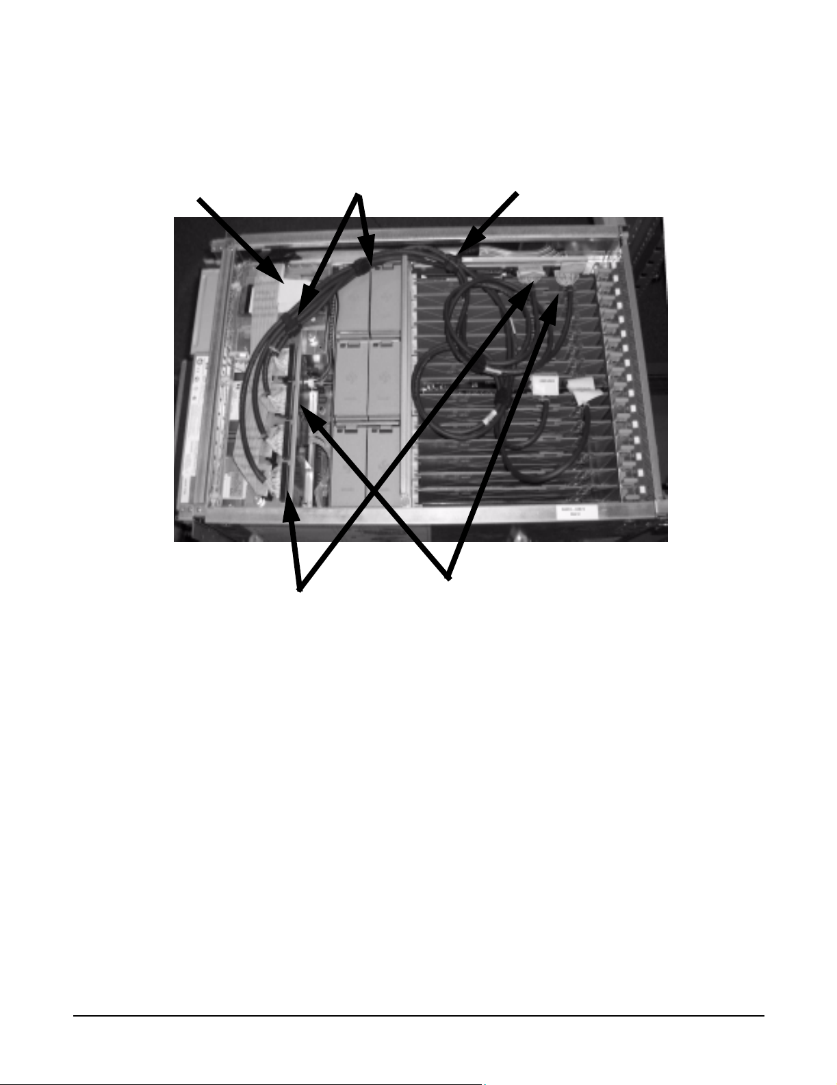
Figure 1-1 shows the correct cabling for a single partition configuration, as viewed from the front of the
server.
Figure 1-1 Smart Array Controller Card with Single Partition Cabling
Port 1/A2
Port 2/A1
Mass Storage Backplane
Connections
Chapter 1
3
Page 8

Cabling for the HP Integrity rx8620 Server
Single Partition RAID Configuration
RAID Cabling for IO Chassis 0 (Top Left and Top Right Hot Plug Hard Drives)
To set up the RAID cabling on the top left and top right hot plug hard drives, do the following:
Step 1. Verify that the HP Smart Array controller card is installed in PCI slot 8 of the IO Chassis 0.
Step 2. Retrieve two cables from the cable kit (A7027-63001).
Step 3. Identify the new cables using the colored cable ties which are contained in the cable kit. For each
cable, use two of the same color tie, one on each end.
NOTE One end of each cable has a pull-tab connected to the SCSI connector which is
labeled “This Connector to PCI Card”. This end of the cable connects to the HP Smart
Array card.
Step 4. Plug the end of one of the cables with the pull-tab into the SCSI connector Port 1/A2 on the Smart
Array card. Repeat for SCSI connector Port 2/A1.
Step 5. Route the cables as shown in Figure 1-3 towards the front of the server and over to the Mass
Storage Backplane connectors.
WARNING The cables must be routed along the side of the server. They must not lay on
top of the flat SCSI ribbon cable bundle or the PCI air dam. Doing so will
damage the cables when the top is installed.
Step 6. Unplug the existing SCSI ribbon cable for the top left HDD. This is the left most connector on the
Mass Storage Backplane when viewed from the front of the server. See Figure 1-3
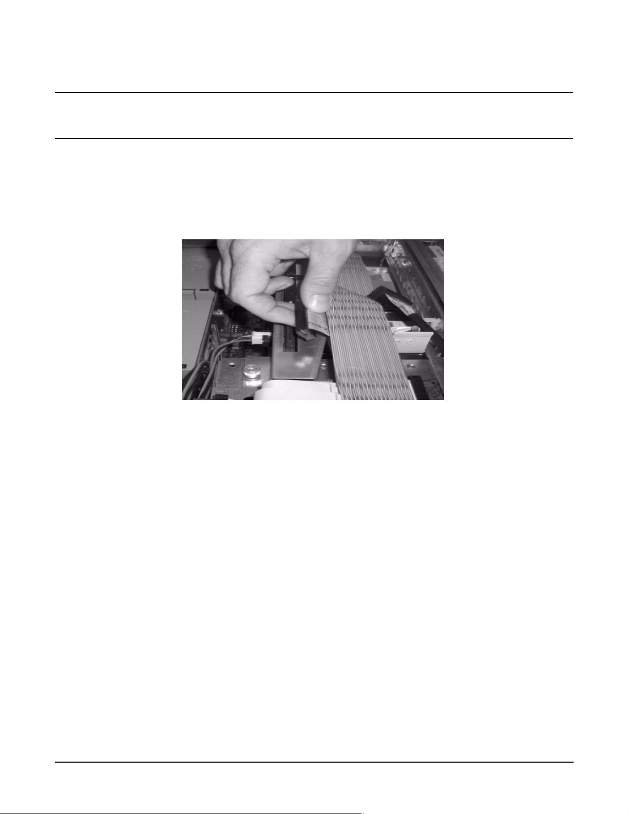
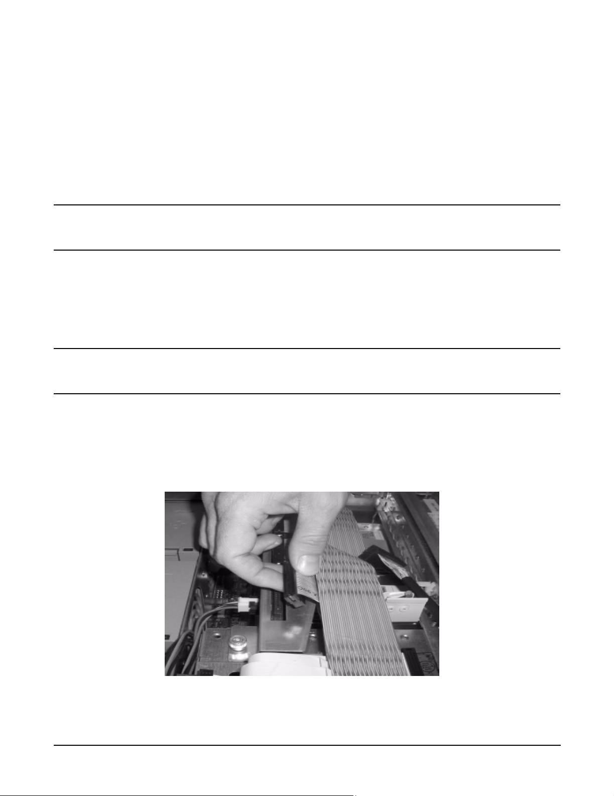
Step 7. Fold the SCSI connector on the ribbon cable so it will lay in front of the connector on the Mass
Storage Backplane. See Figure 1-2.
Figure 1-2 Folded SCSI Connector
Step 8. Plug the new cable from the Smart Array card Port 1/A2 into the mass storage connector for the top
left drive.
4
Chapter 1
Page 9
Cabling for the HP Integrity rx8620 Server
Single Partition RAID Configuration
Step 9. Unplug the existing SCSI ribbon cable for the top right HDD. This is the second connector from the
right on the Mass Storage Bacplane when viewed from the front of the server. See Figure 1-3
Step 10. Fold the SCSI connector on the ribbon cable so it will lay in front of the connector on the Mass
Storage Backplane. See Figure 1-2.
Step 11. Plug the new cable from the Smart Array card Port 2/A1 into the mass storage connector for the top
right drive.
Step 12. Arrange the new cables as shown in Figure 1-3 so that all of the slack is located in the PCI card
cage. The cables must be routed behind the removable media cable bundle and to the side of the air
dam as shown.
Step 13. Loop the cable slack as shown in Figure 1-3.
Step 14. Use the Kwik Wrap ties to secure the cables in the chassis and to maintain the slack. One tie
should secure the cables to the PCI card cage through the lift handle
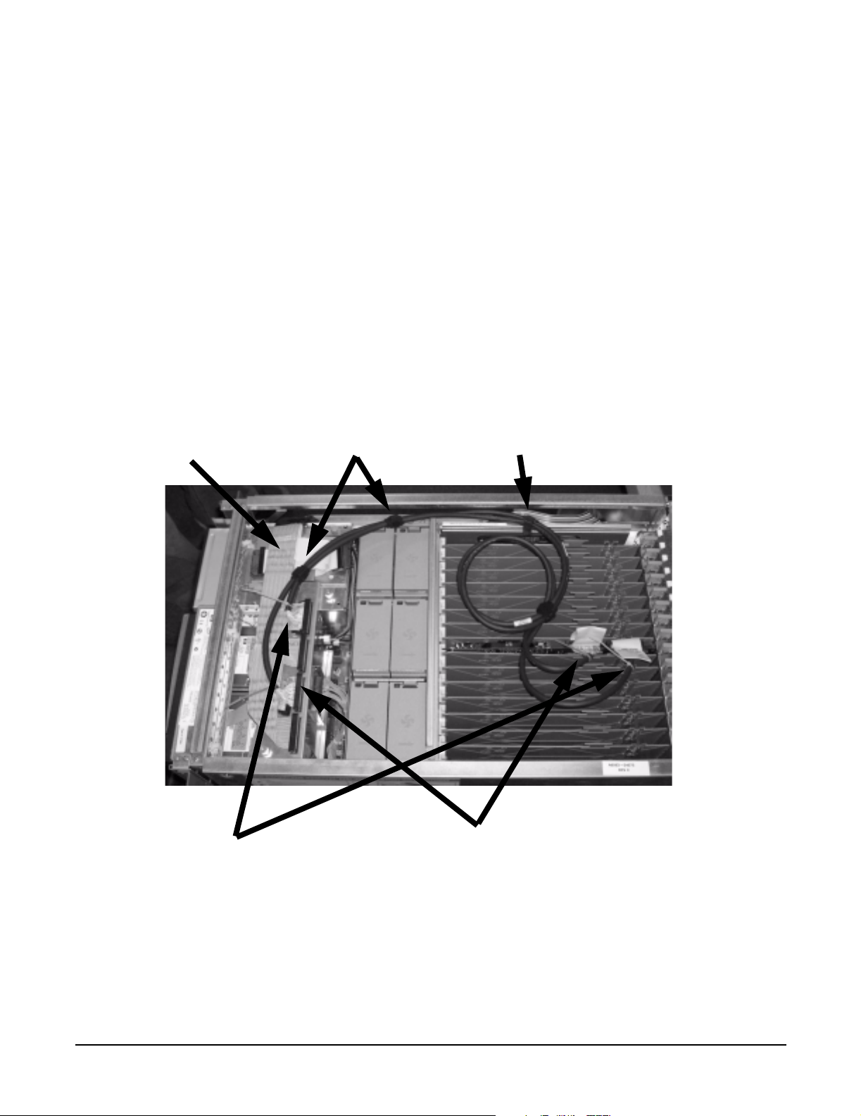
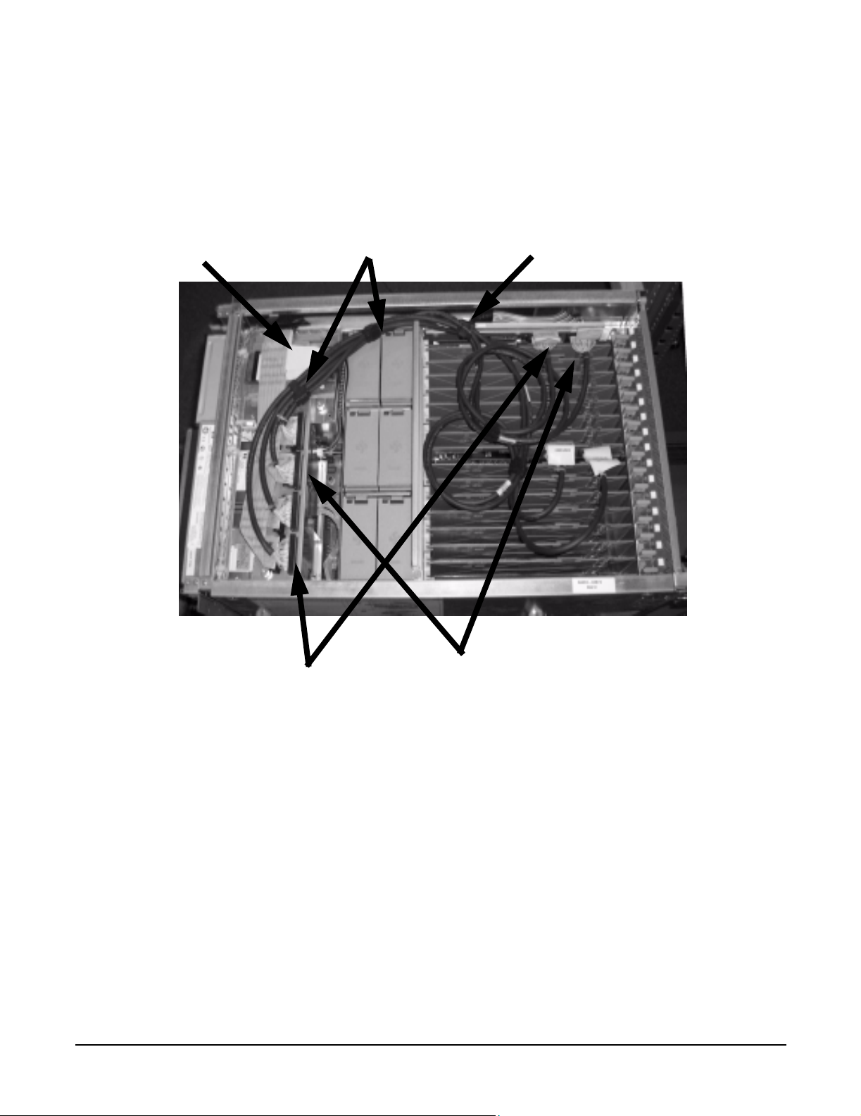
Figure 1-3 Smart Array Controller Card with Single Partition Cabling
Removable Media
Cable Bundle
Cable
Ties
PCI Lift Handle
Chapter 1
Port 1/A2 and Top Left HDD Cable
Connections
Port 2/A1 and Top Right HDD Cable
Connections
5
Page 10
Cabling for the HP Integrity rx8620 Server
Dual Partition Configurations
Dual Partition Configurations
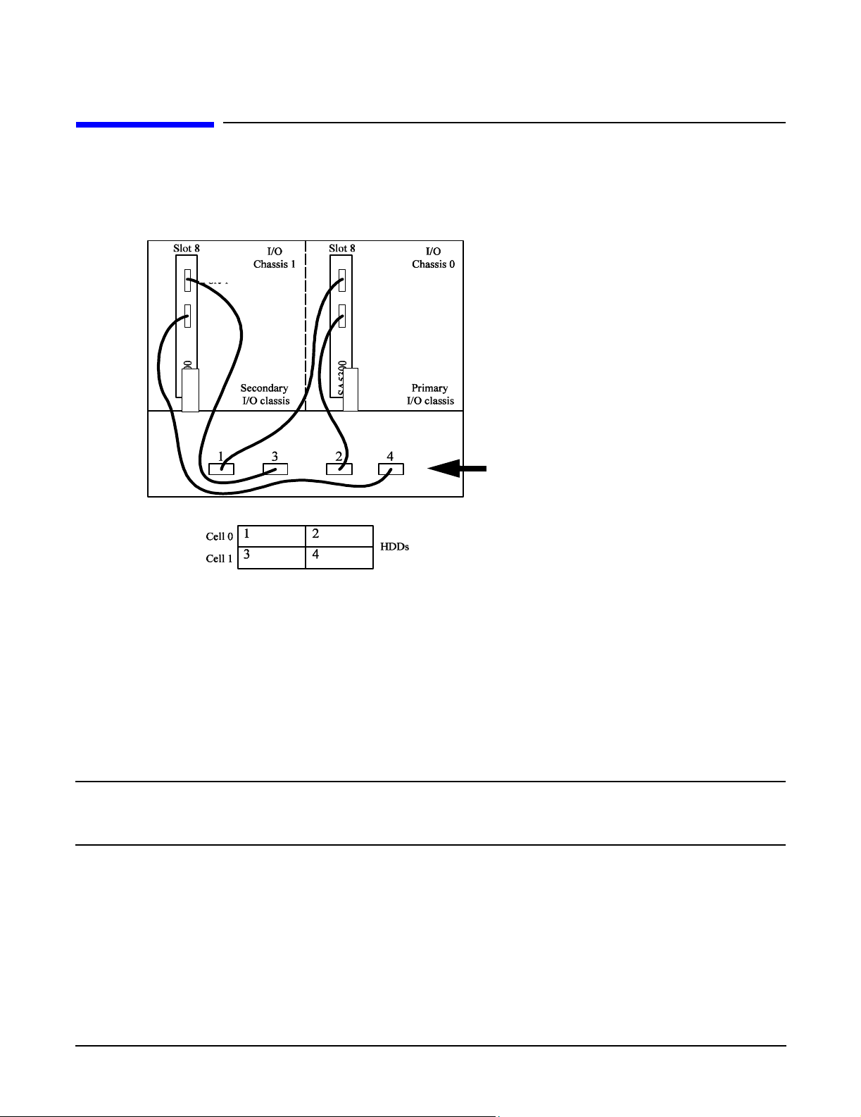
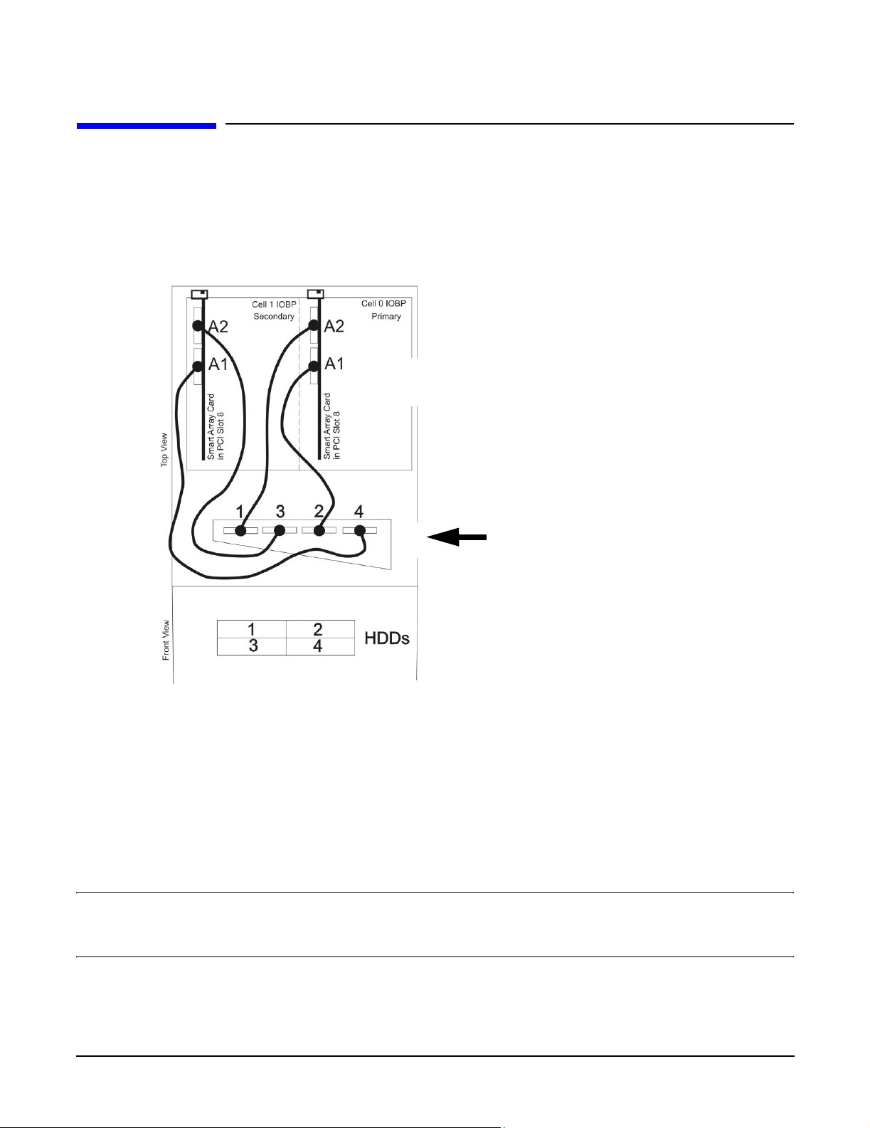
Figure 1-4 shows the correct cabling for a dual partition configuration, as viewed from the front of the server.
Figure 1-4 Smart Array Controller Card with Dual Partition Cabling
Port 1/A2
Port 2/A1
Port 1/A2
Port 2/A1
Mass Storage Backplane
Connections
RAID Cabling for IO Chassis 0 (Top Left and Top Right Hot Plug Hard Drives)
To set up the RAID cabling on the top left and top right hot plug hard drives, do the following:
Step 1. Verify that the HP Smart Array controller card is installed in PCI slot 8 of the IO Chassis 0.
Step 2. Retrieve two cables from the cable kit (A7027-63001).
Step 3. Identify the new cables using the colored cable ties which are also contained in the cable kit. For
each cable, use two of the same color, one on each end.
NOTE One end of each cable has a pull-tab connected to the SCSI connector which is
labeled “This Connector to PCI Card”. This end of the cable connects to the HP Smart
Array card.
Step 4. Plug the end of one of the cables with the pull-tab into the SCSI connector Port 1/A2 on the Smart
Array card. Repeat for SCSI connector Port 2/A1.
Step 5. Route the cables as shown in Figure 1-3 towards the front of the server and over to the Mass
Storage Backplane connectors.
6
Chapter 1
Page 11
Cabling for the HP Integrity rx8620 Server
Dual Partition Configurations
WARNING The cables must be routed along the side of the server. They must not lay on
top of the flat SCSI ribbon cable bundle or the PCI air dam. Doing so will
damage the cables when the top is installed.
Step 6. Unplug the existing SCSI ribbon cable for the top left HDD. This is the left most connector on the
Mass Storage Backplane when viewed from the front of the server. See Figure 1-4
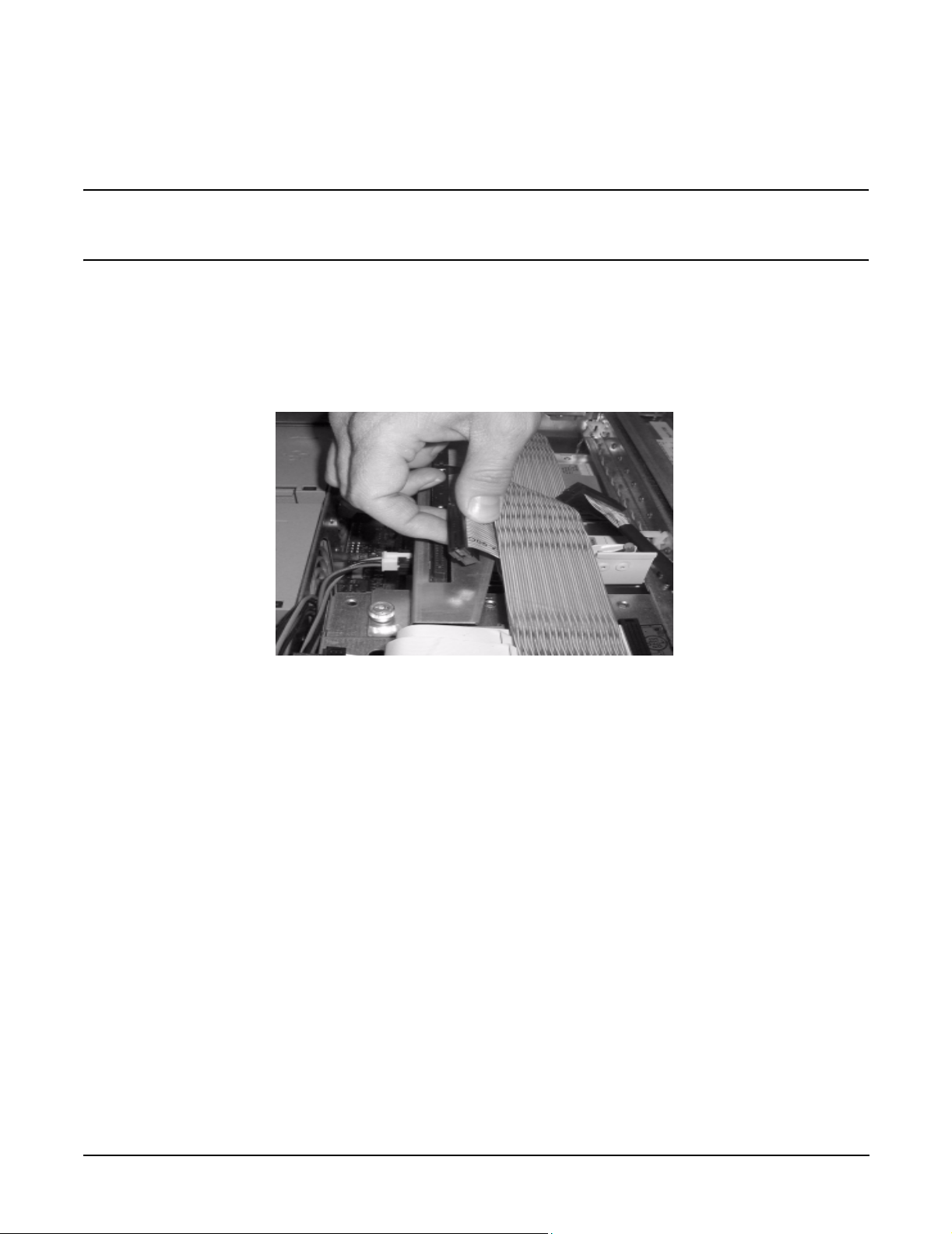
Step 7. Fold the SCSI connector on the ribbon cable so it will lay in front of the connector on the Mass
Storage Backplane. See Figure 1-5.
Figure 1-5 Folded SCSI Connector
Step 8. Plug the new cable from the Smart Array card Port 1/A2 into the mass storage connector for the top
left drive.
Step 9. Unplug the existing SCSI ribbon cable for the top right HDD. This is the second connector from the
right on the Mass Storage Bacplane when viewed from the front of the server. See Figure 1-4
Step 10. Fold the SCSI connector on the ribbon cable so it will lay in front of the connector on the Mass
Storage Backplane.See Figure 1-5.
Step 11. Plug the new cable from the Smart Array card Port 2/A1 into the mass storage connector for the top
right drive.
RAID Cabling for IO Chassis 1 (Bottom Left and Bottom Right Hot Plug Hard Drives)
To set up the RAID cabling on the bottom left and bottom right hot plug hard drives, do the following, from
the front of the server:
Step 1. Verify that the HP Smart Array controller card is installed in PCI slot 8 of IO Chassis 1.
Step 2. Retrieve two cables from the cable kit (A7027-63001).
Step 3. Identify the new cables using the colored cable ties which are also contained in the cable kit (for
each cable, use two of the same color, one on each end). Using a different color tie on each cable
makes it easier to identify the cables for installation and servicing.
Chapter 1
7
Page 12

Cabling for the HP Integrity rx8620 Server
Dual Partition Configurations
NOTE One end of each cable has a pull-tab connected to the SCSI connector which is
labeled “This Connector to PCI Card”. This end of the cable connects to the HP Smart
Array card.
Step 4. Plug the end of one of the cables with the pull-tab into the SCSI connector Port 1/A2 on the Smart
Array card. Repeat for SCSI connector Port 2/A1.
Step 5. Route the cables as shown in Figure 1-6 towards the front of the server and over to the Mass
Storage Backplane connectors.
WARNING The cables must be routed along the side of the PCI card cage and PCI fans.
They must not lay on top of the PCI fans or the PCI air dam. Doing so will
damage the cables.
Step 6. Unplug the existing SCSI ribbon cable for the bottom left HDD. This is the second connector from
the left on the Mass Storage Backplane when viewed from the front of the server. See Figure 1-6
Step 7. Fold the SCSI connector on the ribbon cable so it will lay in front of the connector on the Mass
Storage Backplane. See Figure 1-5.
Step 8. Plug the new cable from the Smart Array card Port 1/A2 into the mass storage connector for the top
left drive.
Step 9. Unplug the existing SCSI ribbon cable for the top right HDD. This is the right most connector on
the Mass Storage Bacplane when viewed from the front of the server. See Figure 1-6
Step 10. Fold the SCSI connector on the ribbon cable so it will lay in front of the connector on the Mass
Storage Backplane. See Figure 1-5.
Step 11. Plug the new cable from the Smart Array card Port 2/A1 into the mass storage connector for the top
right drive.
Step 12. Arrange the new cables as shown in Figure 1-6 so that all of the slack is located in the PCI card
cage. The cables must be routed behind the removable media cable bundle and to the side of the air
dam as shown.
Step 13. Loop the cable slack as shown in Figure 1-6.
Step 14. Use the Kwik Wrap ties to secure the cables in the chassis and to maintain the slack. One tie
should secure the cables to the PCI card cage through the lift handle
Step 15. Arrange the new cables as shown in Figure 1-6 so that all of the slack is located in the PCI card
cage.
Step 16. Loop the cable slack as shown in Figure 1-6. Use the Kwik Wraps to fasten the cables in place and
maintain the slack (this allows servicing of the other PCI cards). See Figure 1-6.
8
Chapter 1
Page 13
Cabling for the HP Integrity rx8620 Server
Dual Partition Configurations
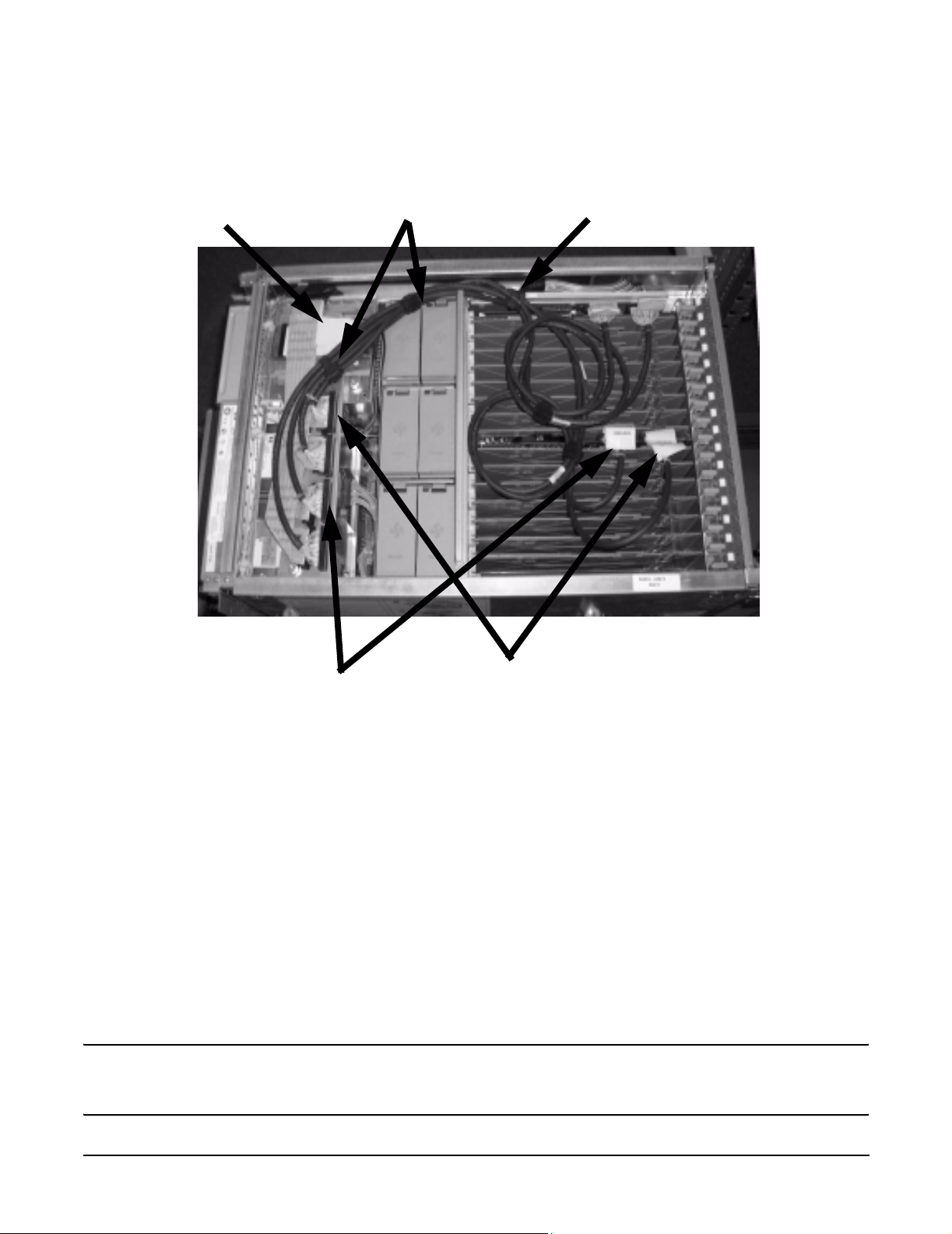
Figure 1-6 Smart Array Controller Card with Dual Partition Cabling
Removable Media
Cable Bundle
Ties
PCI Lift Handle
Chapter 1
Port 2/A1 and Bottom Right HDD
Cable Connections
Port 1/A2 and Bottom Left HDD
Cable Connections
9
Page 14

Cabling for the HP Integrity rx8620 Server
Insight Manager 7 Hard Disk Drive Mapping
Insight Manager 7 Hard Disk Drive Mapping
The previously described internal drive configuration produces the following mapping in IM7 when events
occur on a target HDD, as shown in Table 1-4.
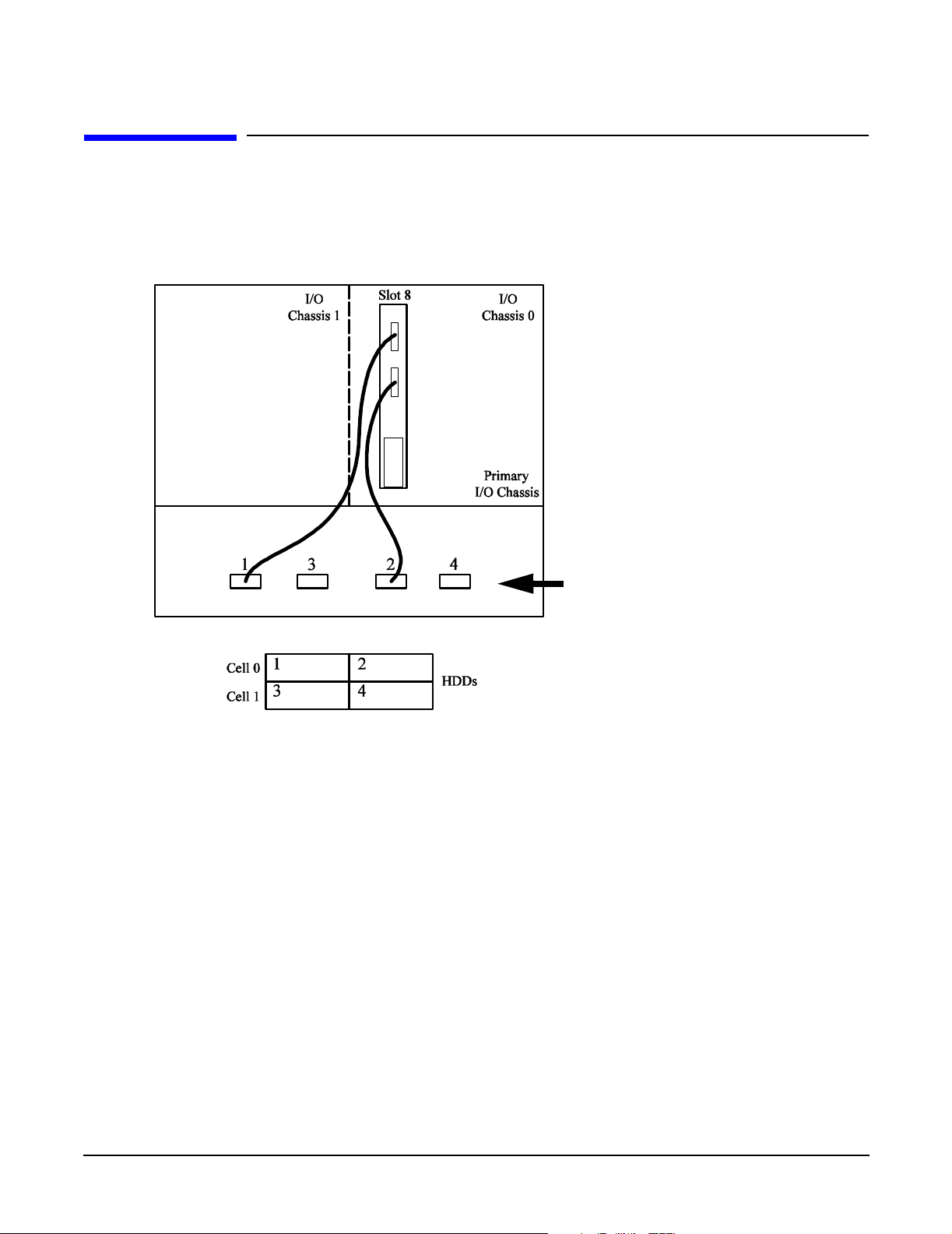
Table 1-4 Hard Drive Mapping for the HP Integrity rx8620 Server
SA5302 or 5304 Card Location HDD Identification
Cabinet
0 0 0 8 0 0 1/A2 6 rx8620
0 0 0 8 0 0 2/A1 6 rx8620
0 0 1 8 0 1 1/A2 6 rx8620
0 0 1 8 0 1 2/A1 6 rx8620
8 0 0 8 8 2 1/A2 6 SEU
8 0 0 8 8 2 2/A1 6 SEU
8 0 1 8 8 3 1/A2 6 SEU
I/O
Bay
I/O
Chassis
Slot Cabinet Cell Port
SCSI
ID
HDD
Location
Physical
Drive
Top Left
Top Right
Bottom Left
Bottom Right
Top Left
Top Right
Bottom Left
8 0 1 8 8 3 2/A1 6 SEU
Bottom Right
10
Chapter 1
Page 15

Cabling for the HP Integrity rx8620 Server
Configuring the Server Firmware and Software for RAID
Configuring the Server Firmware and Software for RAID
To complete the installation and set up RAID for your server's internal hot swap drives, follow the procedures
given in the Smart Array Controller User Guide:
• Configure your HP Smart Array controller card in an HP Integrity server (use HP Smart Array utilities
and command line options from the EFI shell)
• Install and use the operating system-specific HP Smart Array utilities and software that help you
manage your RAID
• Configure the HP Smart Array controller card for an external RAID storage system
Chapter 1
11
Page 16

Cabling for the HP Integrity rx8620 Server
Configuring the Server Firmware and Software for RAID
12
Chapter 1
Page 17
2 Cabling for the HP Integrity rx8640 Server
This chapter describes how to connect the cables of an HP Smart Array controller card to the internal hard
drives of an HP Integrity rx8640 Server.
NOTE These instructions do not apply if you are connecting the controller card to an external mass
storage box. Refer instead to the HP Smart Array Controller User Guide that shipped with your
card.
Table 2-1 shows the product numbers, descriptions and support matrix for the HP Smart Array controllers
supported on the rx8640 server.
Table 2-1 Smart Array Cards Available for the HP Integrity rx8640 Server
Controller Product Number Description
SA6402 A9890A 2 channel / 128 MB cache Y
SA6404 A9891A 4 channel / 256 MB cache Y
Before you begin, you need:
• Cable kit (part number: A7027-63001)
• Smart Array controller card: See Table 2-1 for product numbers.
NOTE The part and product numbers listed in this document are correct as of the release date of the
document. Check http://partsurfer.hp.com for the most current part numbers.
Supported
on rx8640
Installing the HP Smart Array Controller Card
Step 1. If the server is running, shut down the OS, power off the server, and unplug the power cords.
Step 2. Remove the top cover of the server.
Step 3. If only one HP Smart Array controller card is to be installed, install it into slot 8 of IO Chassis 0 for
internal RAID configuration.
Step 4. If two HP Smart Array controller cards are to be installed, install them into slots 8 of IO Chassis 0
and IO Chassis 1 for internal RAID configuration.
NOTE The HP Smart Array controller card must be installed in PCI slot 8 for internal
RAID configurations. If another PCI card is located in slot 8, that card must be
relocated to another slot.
Chapter 2
13
Page 18

Cabling for the HP Integrity rx8640 Server
Single Partition RAID Configuration
Single Partition RAID Configuration
Figure 2-1 shows the correct cabling for a single partition configuration, as viewed from the front of the
server.
Figure 2-1 Smart Array Controller Card with Single Partition Cabling
Mass Storage Backplane
Connections
14
Chapter 2
Page 19
Cabling for the HP Integrity rx8640 Server
Single Partition RAID Configuration
RAID Cabling for IO Chassis 0 (Top Left and Top Right Hot Plug Hard Drives)
To set up the RAID cabling on the top left and top right hot plug hard drives, do the following:
Step 1. Verify that the HP Smart Array controller card is installed in PCI slot 8 of the IO Chassis 0.
Step 2. Retrieve two cables from the cable kit (A7027-63001).
Step 3. Identify the new cables using the colored cable ties which are also contained in the cable kit. For
each cable, use two of the same color tie, one on each end.
NOTE One end of each cable has a pull-tab connected to the SCSI connector which is
labeled “This Connector to PCI Card”. This end of the cable connects to the HP Smart
Array card.
Step 4. Plug the end of one of the cables with the pull-tab into the SCSI connector Port A2 on the Smart
Array card (Port A2 is near the rear of the server). Repeat for SCSI connector Port A1 (Port A1 is
near the center of the board).
Step 5. Route the cables as shown in Figure 2-3 towards the front of the server and over to the Mass
Storage Backplane connectors.
WARNING The cables must be routed along the side of the server. They must not lay on
top of the flat SCSI ribbon cable bundle or the PCI air dam. Doing so will
damage the cables when the top is installed.
Step 6. Unplug the existing SCSI ribbon cable for the top left HDD. This is the left most connector on the
Mass Storage Backplane when viewed from the front of the server. See Figure 2-3
Step 7. Fold the SCSI connector on the ribbon cable so it will lay in front of the connector on the Mass
Storage Backplane. See Figure 2-2.
Figure 2-2 Folded SCSI Connector
Step 8. Plug the new cable from the Smart Array card Port A2 into the mass storage connector for the top
left drive.
Chapter 2
15
Page 20

Cabling for the HP Integrity rx8640 Server
Single Partition RAID Configuration
Step 9. Unplug the existing SCSI ribbon cable for the top right HDD. This is the second connector from the
right on the Mass Storage Bacplane when viewed from the front of the server. See Figure 2-2
Step 10. Fold the SCSI connector on the ribbon cable so it will lay in front of the connector on the Mass
Storage Backplane. See Figure 2-2.
Step 11. Plug the new cable from the Smart Array card Port A1 into the mass storage connector for the top
right drive.
Step 12. Arrange the new cables as shown in Figure 2-2 so that all of the slack is located in the PCI card
cage. The cables must be routed behind the removable media cable bundle and to the side of the air
dam as shown.
Step 13. Loop the cable slack as shown in Figure 2-3.
Step 14. Use the Kwik Wrap ties to secure the cables in the chassis and to maintain the slack. One tie
should secure the cables to the PCI card cage through the lift handle
Figure 2-3 Smart Array Controller Card with Single Partition Cabling
Removable Media
Cable Bundle
Cable
Ties
PCI Lift Handle
16
Port A2 and Top Left HDD Cable
Connections
Port A1 and Top Right HDD Cable
Connections
Chapter 2
Page 21
Cabling for the HP Integrity rx8640 Server
Dual Partition Configurations
Dual Partition Configurations
This section gives instructions for the installation of a second Smart Array Controller Card into the server.
This will provide a dual partition configuration in the server. Figure 2-4 shows the correct cabling for a dual
partition configuration, as viewed from the front of the server.
Figure 2-4 Smart Array Controller Card with Dual Partition Cabling
Mass Storage Backplane
Connections
RAID Cabling for IO Chassis 0 (Top Left and Top Right Hot Plug Hard Drives)
To set up the RAID cabling on the top left and top right hot plug hard drives, do the following:
Step 1. Verify that the HP Smart Array controller card is installed in PCI slot 8 of the IO Chassis 0.
Step 2. Retrieve two cables from the cable kit (A7027-63001).
Step 3. Identify the new cables using the colored cable ties which are also contained in the cable kit. For
each cable, use two of the same color, one on each end.
NOTE One end of each cable has a pull-tab connected to the SCSI connector which is
labeled “This Connector to PCI Card”. This end of the cable connects to the HP Smart
Array card.
Step 4. Plug the end of one of the cables with the pull-tab into the SCSI connector Port A2 on the Smart
Array card (Port 1 is near the rear of the server). Repeat for SCSI connector Port A1 (Port 2 is near
the center of the board).
Chapter 2
17
Page 22
Cabling for the HP Integrity rx8640 Server
Dual Partition Configurations
Step 5. Route the cables as shown in Figure 2-3 towards the front of the server and over to the Mass
Storage Backplane connectors.
WARNING The cables must be routed along the side of the server. They must not lay on
top of the flat SCSI ribbon cable bundle or the PCI air dam. Doing so will
damage the cables when the top is installed.
Step 6. Unplug the existing SCSI ribbon cable for the top left HDD. This is the left most connector on the
Mass Storage Backplane when viewed from the front of the server. See Figure 2-3
Step 7. Fold the SCSI connector on the ribbon cable so it will lay in front of the connector on the Mass
Storage Backplane. See Figure 2-5.
Figure 2-5 Folded SCSI Connector
Step 8. Plug the new cable from the Smart Array card Port A2 into the mass storage connector for the top
left drive.
Step 9. Unplug the existing SCSI ribbon cable for the top right HDD. This is the second connector from the
right on the Mass Storage Bacplane when viewed from the front of the server. See Figure 2-3
Step 10. Fold the SCSI connector on the ribbon cable so it will lay in front of the connector on the Mass
Storage Backplane.See Figure 2-5.
Step 11. Plug the new cable from the Smart Array card Port A1 into the mass storage connector for the top
right drive.
18
Chapter 2
Page 23
Cabling for the HP Integrity rx8640 Server
Dual Partition Configurations
Figure 2-6 Smart Array Controller Card with Dual Partition Cabling
Removable Media
Cable Bundle
Ties
PCI Lift Handle
Port A1 and Top Right HDD
Cable Connections
Port A2 and Top Left HDD
Cable Connections
RAID Cabling for IO Chassis 1 (Bottom Left and Bottom Right Hot Plug Hard Drives)
To set up the RAID cabling on the bottom left and bottom right hot plug hard drives, do the following, from
the front of the server:
Step 1. Verify that the HP Smart Array controller card is installed in PCI slot 8 of IO Chassis 1.
Step 2. Retrieve two cables from the cable kit (A7027-63001).
Step 3. Identify the new cables using the colored cable ties which are also contained in the cable kit (for
each cable, use two of the same color, one on each end). Using a different color tie on each cable
makes it easier to identify the cables for installation and servicing.
NOTE One end of each cable has a pull-tab connected to the SCSI connector which is
labeled “This Connector to PCI Card”. This end of the cable connects to the HP Smart
Array card.
Chapter 2
19
Page 24

Cabling for the HP Integrity rx8640 Server
Dual Partition Configurations
Step 4. Plug the end of one of the cables with the pull-tab into the SCSI connector Port A2 on the Smart
Array card (Port 1 is near the rear of the server). Repeat for SCSI connector Port A1 (Port 2 is near
the center of the board).
Step 5. Route the cables as shown in Figure 2-7 towards the front of the server and over to the Mass
Storage Backplane connectors.
WARNING The cables must be routed along the side of the PCI card cage and PCI fans.
They must not lay on top of the PCI fans or the PCI air dam. Doing so will
damage the cables.
Step 6. Unplug the existing SCSI ribbon cable for the bottom left HDD. This is the second connector from
the left on the Mass Storage Backplane when viewed from the front of the server. See Figure 2-7
Step 7. Fold the SCSI connector on the ribbon cable so it will lay in front of the connector on the Mass
Storage Backplane. See Figure 2-5.
Step 8. Plug the new cable from the Smart Array card Port A2 into the mass storage connector for the top
left drive.
Step 9. Unplug the existing SCSI ribbon cable for the top right HDD. This is the right most connector on
the Mass Storage Bacplane when viewed from the front of the server. See Figure 2-7
Step 10. Fold the SCSI connector on the ribbon cable so it will lay in front of the connector on the Mass
Storage Backplane. See Figure 2-5.
Step 11. Plug the new cable from the Smart Array card Port A1 into the mass storage connector for the top
right drive.
Step 12. Arrange the new cables as shown in Figure 2-7 so that all of the slack is located in the PCI card
cage. The cables must be routed behind the removable media cable bundle and to the side of the air
dam as shown.
Step 13. Loop the cable slack as shown in Figure 2-7.
Step 14. Use the Kwik Wrap ties to secure the cables in the chassis and to maintain the slack. One tie
should secure the cables to the PCI card cage through the lift handle
Step 15. Arrange the new cables as shown in Figure 2-7 so that all of the slack is located in the PCI card
cage.
Step 16. Loop the cable slack as shown in Figure 2-7. Use the Kwik Wraps to fasten the cables in place and
maintain the slack (this allows servicing of the other PCI cards).
20
Chapter 2
Page 25
Cabling for the HP Integrity rx8640 Server
Dual Partition Configurations
Figure 2-7 Smart Array Controller Card with Dual Partition Cabling
Removable Media
Cable Bundle
Ties
PCI Lift Handle
Port A1 and Bottom Right HDD
Cable Connections
Port A2 and Bottom Left HDD
Cable Connections
Chapter 2
21
Page 26
Cabling for the HP Integrity rx8640 Server
Insight Manager 7 Hard Disk Drive Mapping
Insight Manager 7 Hard Disk Drive Mapping
The previously described internal drive configuration produces the following mapping in IM7 when events
occur on a target HDD, as shown in Table 2-2.
Table 2-2 Hard Drive Mapping for the HP Integrity rx8620 Server
SA5302 or 5304 Card Location HDD Identification
Cabinet
0 0 0 8 0 0 A2 6 rx8620
0 0 0 8 0 0 A1 6 rx8620
0 0 1 8 0 1 A2 6 rx8620
0 0 1 8 0 1 A1 6 rx8620
8 0 0 8 8 2 A2 6 SEU
8 0 0 8 8 2 A1 6 SEU
8 0 1 8 8 3 A2 6 SEU
I/O
Bay
I/O
Chassis
Slot Cabinet Cell Port
SCSI
ID
HDD
Location
Physical
Drive
Top Left
Top Right
Bottom Left
Bottom Right
Top Left
Top Right
Bottom Left
8 0 1 8 8 3 A1 6 SEU
Bottom Right
22
Chapter 2
Page 27

Cabling for the HP Integrity rx8640 Server
Configuring the Server Firmware and Software for RAID
Configuring the Server Firmware and Software for RAID
To complete the installation and set up RAID for your server's internal hot swap drives, follow the procedures
given in the Smart Array Controller User Guide:
• Configure your HP Smart Array controller card in an HP Integrity server (use HP Smart Array utilities
and command line options from the EFI shell)
• Install and use the operating system-specific HP Smart Array utilities and software that help you
manage your RAID
• Configure the HP Smart Array controller card for an external RAID storage system
Chapter 2
23
Page 28

Cabling for the HP Integrity rx8640 Server
Configuring the Server Firmware and Software for RAID
24
Chapter 2
Page 29
3 Cabling for the Server Expansion Unit
This chapter describes how to connect the cables of an HP Smart Array controller card to the internal hard
drives of a Server or Server Expansion Unit (SEU) connected to an HP Integrity rx8620 or rx8640 server.
NOTE These instructions do not apply if you are connecting the controller card to an external mass
storage box. Refer instead to the HP Smart Array Controller User Guide that shipped with your
card.
Table 3-1 shows the product numbers, descriptions and support matrix for the HP Smart Array controllers
supported on the rx8620 and rx8640 servers. If a card is supported in a server, that card is also supported in a
SEU connected to that server.
Table 3-1 Smart Array Cards Available for the HP Integrity rx8620 Server
Controller Product Number Description
SA5302 A9825A 2 channel / 128 MB cache Y N
SA5304 A9826A 4 channel / 256 MB cache Y N
SA6402 A9890A 2 channel / 128 MB cache Y Y
SA6404 A9891A 4 channel / 256 MB cache Y Y
NOTE When cabling an HP Smart Array controller card to the Server Expansion Unit (SEU), the
PCI-X I/O and SCSI HDD Backplane architecture are identical in the rx8620/rx8640 server
and in the Server Expansion Unit. Adding the Server Expansion Unit allows for a 3-partition
or 4-partition configuration.
Before you begin, you need:
• Cable kit (part number: A7027-63001)
• Smart Array controller card: See Table 3-1 for product numbers.
NOTE The part and product numbers listed in this document are correct as of the release date of the
document. Check http://partsurfer.hp.com for the most current part numbers.
Supported
on rx8620
Supported
on rx8640
Chapter 3
25
Page 30

Cabling for the Server Expansion Unit
HP Smart Array Controller Card Ports
HP Smart Array Controller Card Ports
The ports on the HP Smart Array Controller Cards are labeled as shown in Table 3-2
Table 3-2 HP Smart Array Controller Card Port Labels
Controller Card Port Location
SA 5302/SA5304 Port 1 Port near bulkhead
Port 2 Port near center of card
SA 6402/SA6404 Port A2 Port near bulkhead
Port A1 Port near center of card
When a port is referenced in this document the following notation is used. See Figure 3-1 for additional
information.
Table 3-3 Port Identification Notation
Notation Port Location
Port 1/A2 Port near bulkhead
Port 2/A1 Port near center of
card
Installing the HP Smart Array Controller Card
Step 1. If the server is running, shut down the OS, power off the server, and unplug the power cords.
Step 2. Remove the top cover of the SEU.
Step 3. If only one HP Smart Array controller card is to be installed, install it into slot 8 of IO Chassis 0 for
internal RAID configuration.
Step 4. If two HP Smart Array controller cards are to be installed, install them into slots 8 of IO Chassis 0
and IO Chassis 1 for internal RAID configuration.
NOTE The HP Smart Array controller card must be installed in PCI slot 8 for internal
RAID configurations. If another PCI card is located in slot 8, that card must be
relocated to another slot.
26
Chapter 3
Page 31

Cabling for the Server Expansion Unit
Single Partition RAID Configuration
Single Partition RAID Configuration
Figure 3-1 shows the correct cabling for a single partition configuration, as viewed from the front of the SEU.
Figure 3-1 Smart Array Controller Card with Single Partition Cabling
Port 1/A2
Port 2/A1
Mass Storage Backplane
Connections
Chapter 3
27
Page 32

Cabling for the Server Expansion Unit
Single Partition RAID Configuration
RAID Cabling for IO Chassis 0 (Top Left and Top Right Hot Plug Hard Drives)
To set up the RAID cabling on the top left and top right hot plug hard drives, do the following:
Step 1. Verify that the HP Smart Array controller card is installed in PCI slot 8 of the IO Chassis 0.
Step 2. Retrieve two cables from the cable kit (A7027-63001).
Step 3. Identify the new cables using the colored cable ties which are also contained in the cable kit. For
each cable, use two of the same color tie, one on each end.
NOTE One end of each cable has a pull-tab connected to the SCSI connector which is
labeled “This Connector to PCI Card”. This end of the cable connects to the HP Smart
Array card.
Step 4. Plug the end of one of the cables with the pull-tab into the SCSI connector Port 1/A2 on the Smart
Array card. Repeat for SCSI connector Port 2 /A1.
Step 5. Route the cables as shown in Figure 3-3 towards the front of the server and over to the Mass
Storage Backplane connectors.
WARNING The cables must be routed along the side of the SEU. They must not lay on
top of the flat SCSI ribbon cable bundle or the PCI air dam. Doing so will
damage the cables when the top is installed.
Step 6. Unplug the existing SCSI ribbon cable for the top left HDD. This is the left most connector on the
Mass Storage Backplane when viewed from the front of the server. See Figure 3-1
Step 7. Fold the SCSI connector on the ribbon cable so it will lay in front of the connector on the Mass
Storage Backplane. See Figure 3-2.
Figure 3-2 Folded SCSI Connector
Step 8. Plug the new cable from the Smart Array card Port 1/A2 into the mass storage connector for the top
left drive.
28
Chapter 3
Page 33

Cabling for the Server Expansion Unit
Single Partition RAID Configuration
Step 9. Unplug the existing SCSI ribbon cable for the top right HDD. This is the second connector from the
right on the Mass Storage Bacplane when viewed from the front of the server. See Figure 3-3
Step 10. Fold the SCSI connector on the ribbon cable so it will lay in front of the connector on the Mass
Storage Backplane. See Figure 3-2.
Step 11. Plug the new cable from the Smart Array card Port 2/A1 into the mass storage connector for the top
right drive.
Step 12. Arrange the new cables as shown in Figure 3-3 so that all of the slack is located in the PCI card
cage. The cables must be routed behind the removable media cable bundle and to the side of the air
dam as shown.
Step 13. Loop the cable slack as shown in Figure 3-3.
Step 14. Use the Kwik Wrap ties to secure the cables in the chassis and to maintain the slack. One tie
should secure the cables to the PCI card cage through the lift handle
Figure 3-3 Smart Array Controller Card with Single Partition Cabling
Removable Media
Cable Bundle
Cable
Ties
PCI Lift Handle
Chapter 3
Port 1 and Top Left HDD Cable
Connections
Port 2 and Top Right HDD Cable
Connections
29
Page 34

Cabling for the Server Expansion Unit
Dual Partition Configurations
Dual Partition Configurations
Figure 3-4 shows the correct cabling for a dual partition configuration, as viewed from the front of the SEU.
Figure 3-4 Smart Array Controller Card with Dual Partition Cabling
Port 1/A2
Port 2/A1
Port 1/A2
Port 2/A1
Mass Storage Backplane
Connections
RAID Cabling for IO Chassis 0 (Top Left and Top Right Hot Plug Hard Drives)
To set up the RAID cabling on the top left and top right hot plug hard drives, do the following:
Step 1. Verify that the HP Smart Array controller card is installed in PCI slot 8 of the IO Chassis 0.
Step 2. Retrieve two cables from the cable kit (A7027-63001).
Step 3. Identify the new cables using the colored cable ties which are also contained in the cable kit. For
each cable, use two of the same color, one on each end.
NOTE One end of each cable has a pull-tab connected to the SCSI connector which is
labeled “This Connector to PCI Card”. This end of the cable connects to the HP Smart
Array card.
Step 4. Plug the end of one of the cables with the pull-tab into the SCSI connector Port 1/A2 on the Smart
Array card. Repeat for SCSI connector Port 2A1.
Step 5. Route the cables as shown in Figure 3-3 towards the front of the server and over to the Mass
Storage Backplane connectors.
30
Chapter 3
Page 35

Cabling for the Server Expansion Unit
Dual Partition Configurations
WARNING The cables must be routed along the side of the server. They must not lay on
top of the flat SCSI ribbon cable bundle or the PCI air dam. Doing so will
damage the cables when the top is installed.
Step 6. Unplug the existing SCSI ribbon cable for the top left HDD. This is the left most connector on the
Mass Storage Backplane when viewed from the front of the server. See Figure 3-1
Step 7. Fold the SCSI connector on the ribbon cable so it will lay in front of the connector on the Mass
Storage Backplane. See Figure 3-5.
Figure 3-5 Folded SCSI Connector
Step 8. Plug the new cable from the Smart Array card Port 1/A2 into the mass storage connector for the top
left drive.
Step 9. Unplug the existing SCSI ribbon cable for the top right HDD. This is the second connector from the
right on the Mass Storage Bacplane when viewed from the front of the server. See Figure 3-1
Step 10. Fold the SCSI connector on the ribbon cable so it will lay in front of the connector on the Mass
Storage Backplane.See Figure 3-5.
Step 11. Plug the new cable from the Smart Array card Port 2/A1 into the mass storage connector for the top
right drive.
RAID Cabling for IO Chassis 1 (Bottom Left and Bottom Right Hot Plug Hard Drives)
To set up the RAID cabling on the bottom left and bottom right hot plug hard drives, do the following, from
the front of the server:
Step 1. Verify that the HP Smart Array controller card is installed in PCI slot 8 of IO Chassis 1.
Step 2. Retrieve two cables from the cable kit (A7027-63001).
Step 3. Identify the new cables using the colored cable ties which are also contained in the cable kit (for
each cable, use two of the same color, one on each end). Using a different color tie on each cable
makes it easier to identify the cables for installation and servicing.
Chapter 3
31
Page 36

Cabling for the Server Expansion Unit
Dual Partition Configurations
NOTE One end of each cable has a pull-tab connected to the SCSI connector which is
labeled “This Connector to PCI Card”. This end of the cable connects to the HP Smart
Array card.
Step 4. Plug the end of one of the cables with the pull-tab into the SCSI connector Port 1A2 on the Smart
Array card. Repeat for SCSI connector Port 2/A1.
Step 5. Route the cables as shown in Figure 3-6 towards the front of the server and over to the Mass
Storage Backplane connectors.
WARNING The cables must be routed along the side of the PCI card cage and PCI fans.
They must not lay on top of the PCI fans or the PCI air dam. Doing so will
damage the cables.
Step 6. Unplug the existing SCSI ribbon cable for the bottom left HDD. This is the second connector from
the left on the Mass Storage Backplane when viewed from the front of the server. See Figure 3-6
Step 7. Fold the SCSI connector on the ribbon cable so it will lay in front of the connector on the Mass
Storage Backplane. See Figure 3-5.
Step 8. Plug the new cable from the Smart Array card Port 1A2 into the mass storage connector for the top
left drive.
Step 9. Unplug the existing SCSI ribbon cable for the top right HDD. This is the right most connector on
the Mass Storage Bacplane when viewed from the front of the server. See Figure 3-6
Step 10. Fold the SCSI connector on the ribbon cable so it will lay in front of the connector on the Mass
Storage Backplane. See Figure 3-5.
Step 11. Plug the new cable from the Smart Array card Port 2/A1 into the mass storage connector for the top
right drive.
Step 12. Arrange the new cables as shown in Figure 3-6 so that all of the slack is located in the PCI card
cage. The cables must be routed behind the removable media cable bundle and to the side of the air
dam as shown.
Step 13. Loop the cable slack as shown in Figure 3-6.
Step 14. Use the Kwik Wrap ties to secure the cables in the chassis and to maintain the slack. One tie
should secure the cables to the PCI card cage through the lift handle
Step 15. Arrange the new cables as shown in Figure 3-6 so that all of the slack is located in the PCI card
cage.
Step 16. Loop the cable slack as shown in Figure 3-6. Use the Kwik Wraps to fasten the cables in place and
maintain the slack (this allows servicing of the other PCI cards).
32
Chapter 3
Page 37

Cabling for the Server Expansion Unit
Dual Partition Configurations
Figure 3-6 Smart Array Controller Card with Dual Partition Cabling
Removable Media
Cable Bundle
Ties
PCI Lift Handle
Chapter 3
Port 2 and Bottom Right HDD
Cable Connections
Port 1 and Bottom Left HDD
Cable Connections
33
Page 38

Cabling for the Server Expansion Unit
Insight Manager 7 Hard Disk Drive Mapping
Insight Manager 7 Hard Disk Drive Mapping
The previously described internal drive configuration produces the following mapping in IM7 when events
occur on a target HDD, as shown in Table 3-4.
Table 3-4 Hard Drive Mapping for the HP Integrity rx8620 Server
SA5302 or 5304 Card Location HDD Identification
Cabinet
0 0 0 8 0 0 1/A2 6 rx8620
0 0 0 8 0 0 2/A1 6 rx8620
0 0 1 8 0 1 1/A2 6 rx8620
0 0 1 8 0 1 2/A1 6 rx8620
8 0 0 8 8 2 1/A2 6 SEU
8 0 0 8 8 2 2/A1 6 SEU
8 0 1 8 8 3 1/A2 6 SEU
I/O
Bay
I/O
Chassis
Slot Cabinet Cell Port
SCSI
ID
HDD
Location
Physical
Drive
Top Left
Top Right
Bottom Left
Bottom Right
Top Left
Top Right
Bottom Left
8 0 1 8 8 3 2/A1 6 SEU
Bottom Right
34
Chapter 3
Page 39

Cabling for the Server Expansion Unit
Configuring the Server Firmware and Software for RAID
Configuring the Server Firmware and Software for RAID
To complete the installation and set up RAID for your server's internal hot swap drives, follow the procedures
given in the Smart Array Controller User Guide:
• Configure your HP Smart Array controller card in an HP Integrity server (use HP Smart Array utilities
and command line options from the EFI shell)
• Install and use the operating system-specific HP Smart Array utilities and software that help you
manage your RAID
• Configure the HP Smart Array controller card for an external RAID storage system
Chapter 3
35
Page 40

Cabling for the Server Expansion Unit
Configuring the Server Firmware and Software for RAID
36
Chapter 3
Page 41

4 Cabling for the HP Integrity rx7620 Server
This chapter describes how to connect the cables of an HP Smart Array 6402 or 6404 controller card to the
internal hard drives of an HP Integrity rx7620 Server.
NOTE These instructions do not apply if you are connecting the controller card to an external mass
storage box. Refer instead to the HP Smart Array Controller User Guide that shipped with your
card.
The Smart Array 6400 series of controller cards includes two models: the 6402 and the 6404. Model 6402 has
two Wide Ultra320 SCSI channels and 128 MB of cache. Model 6404 has four Wide Ultra320 SCSI channels
and 256 MB of cache.
Table 4-1 shows the product numbers and descriptions for these cards.
Table 4-1 Smart Array Cards Available for the HP Integrity rx7620 Server
Controller Product Number Description
SA6402 A9890A 2 channel / 128 MB cache
SA6404 A9891A 4 channel / 256 MB cache
Before you begin, you need:
• Cable kit (part number: A7027-63001)
• T-15 Torx driver
• 3/16-inch hex driver
• Smart Array controller card
Installing the HP Smart Array 6402 or 6404 Controller Card
Step 1. If the server is running, shut down the OS, power off the server, and unplug the power cord.
Step 2. Remove the top cover of the server.
Step 3. If only one HP Smart Array controller card is to be installed, install it into slot 7 of IO Chassis 1 for
internal RAID configuration.
Step 4. If two HP Smart Array controller cards are to be installed, install one into slot 8 of IO Chassis 0
and the other into slot 7 of IO Chassis 1 for internal RAID configuration.
Chapter 4
NOTE The HP Smart Array 6402 or 6404 controller card must be installed in PCI slot 8 in
IO Chassis 0 and PCI slot 7 in IO Chassis 1 for internal RAID cabeling. If another
PCI card is installed in these slots it must relocated to another slot. The LAN SCSI
Core IO card is installed in slot 8 of IO Chassis 1. If a second LAN SCSI card is
installed it will be in slot 1 of IO Chassis 0.
37
Page 42

Cabling for the HP Integrity rx7620 Server
Recabling for RAID
Recabling for RAID
From the factory, the internal hot plug drives for the HP Integrity rx7620 server are connected to the
integrated SCSI card as follows (when viewed from the front of the server):
• The top left hard drive has a SCSI connector cabled to the management processor (MP) card
• The top right hard drive has a SCSI connector cabled to the Core I/O slot 8 cell 1
• The bottom left and right hard drive has a SCSI connector cabled to internal SCSI cell 0
To use RAID with your hot plug drives, you must disconnect the internal SCSI cables from their embedded
controller and use the Cable kit (A7027-63001). Then follow the appropriate set of instructions given below.
Single Partition Configuration
Figure 4-1 shows the correct cabling for a single partition configuration, as viewed from the front of the
server.
Figure 4-1 Smart Array Controller Card with Single Partition Cabling
38
Chapter 4
Page 43

Cabling for the HP Integrity rx7620 Server
Recabling for RAID
Setting up RAID Cabling for IO Chassis 1 (Top Left and Top Right Hot Plug Hard Drives)
To set up the RAID cabling on the top left and top right hot plug hard drives, do the following:
Step 1. Verify that the HP Smart Array controller card is installed in PCI slot 1-7.
Step 2. Retrieve two cables from the cable kit (A7027-63001).
Step 3. Identify the new cables using the colored cable ties which are also contained in the cable kit. For
each cable, use two of the same color, one on each end.
NOTE One end of each cable has a pull-tab connected to the SCSI connector which is
labeled “This Connector to PCI Card”. This end of the cable connects to the HP Smart
Array card.
Step 4. Plug the end of the cable with the pull-tab into the SCSI connector port A1 on the Smart Array
card. Repeat for SCSI connector port A2.
Step 5. Route the other end of the cables out through the left hand side of the server.
Step 6. Route the cables towards the front of the server and over to the mass storage connectors.
Step 7. Unplug the existing SCSI ribbon cables for the top left and top right HDDs (use the label behind
the connectors to determine which connector goes to which drive).
Step 8. Plug the new cable from the Smart Array card Port A2 (closest to the bracket) into the mass storage
connector for the top left drive.
Step 9. Plug the new cable from the Smart Array card Port A1 (closest to the center of the board) into the
mass storage connector for the top right drive.
Step 10. Arrange the new cables so that all of the slack is located in the PCI area.
Step 11. Fold the cable slack and wrap a Kwik Wrap around it to maintain the slack (this allows servicing of
the other PCI cards).
Step 12. Leave the un-plugged SCSI ribbon cable to rest just in front of the SCSI connector.
Figure 4-2 shows what the cabling looks like when installed.
Chapter 4
39
Page 44

Cabling for the HP Integrity rx7620 Server
Recabling for RAID
Figure 4-2 Smart Array 6402 Controller Card with Single Partition Cabling
Port A2 and Top Left
HDD Cabling
Port A1 and Top Right
HDD Cabling
40
Chapter 4
Page 45

Cabling for the HP Integrity rx7620 Server
Recabling for RAID
Dual Partition Configurations
Figure 4-3 shows the correct cabling for a dual partition configuration, as viewed from the front of the server.
Figure 4-3 Smart Array 6402 or 6404 Controller Card with Dual Partition Cabling
Setting up RAID Cabling for IO Chassis 1 (Top Left and Top Right Hot Plug Hard Drives)
To set up the RAID cabling on the top left and top right hot plug hard drives, do the following:
Step 1. Verify that the HP Smart Array controller card is installed in PCI slot 1-7.
Step 2. Retrieve two cables from the cable kit (A7027-63001).
Step 3. Identify the new cables using the colored cable ties which are also contained in the cable kit. For
each cable, use two of the same color, one on each end.
NOTE One end of each cable has a pull-tab connected to the SCSI connector which is
labeled “This Connector to PCI Card”. This end of the cable connects to the HP Smart
Array card.
Step 4. Plug the end of the cable with the pull-tab into the SCSI connector port A1 on the Smart Array
card. Repeat for SCSI connector port A2.
Step 5. Route the other end of the cables out through the left hand side of the server.
Step 6. Route the cables towards the front of the server and over to the mass storage connectors.
Step 7. Unplug the existing SCSI ribbon cables for the top left and top right HDDs (use the label behind
the connectors to determine which connector goes to which drive).
Chapter 4
41
Page 46

Cabling for the HP Integrity rx7620 Server
Recabling for RAID
Step 8. Plug the new cable from the Smart Array card Port A2 (closest to the bracket) into the mass storage
connector for the top left drive. See Figure 4-3.
Step 9. Plug the new cable from the Smart Array card Port A1 (closest to the center of the board) into the
mass storage connector for the top right drive. See Figure 4-3.
Step 10. Arrange the new cables so that all of the slack is located in the PCI area.
Step 11. Fold the cable slack and wrap a Kwik Wrap around it to maintain the slack (this allows servicing of
the other PCI cards).
Setting up RAID Cabling for IO Chassis 0 (Bottom Hot Plug Hard Drives)
To set up the RAID cabling on the bottom hot plug hard drives, do the following, from the front of the server:
Step 1. Verify that the HP Smart Array 6402 or 6404 controller card is installed in PCI slot 0-8. Refer to
HP Smart Array 6400 User Guide.
Step 2. Retrieve one cable from the cable kit (A7027-63001).
Step 3. Identify the new cable using the colored cable ties which are also contained in the cable kit (use two
of the same color, one on each end).
Step 4. Plug the end of the cable with the pull-tab into the SCSI connector port A1 on the Smart Array
card. See Figure 4-3.
Step 5. Route the other end of the cable out through the left hand side of the server.
Step 6. Route the cable towards the front of the server and over to the mass storage connectors.
Step 7. Unplug the existing SCSI ribbon cable for the bottom HDDs. This is the center connector ont he
Mass Storage Backplane.
Step 8. Plug the new cable from the Smart Array card into the mass storage connector for the bottom
HDDs.
Step 9. Arrange the new cables so that all the slack is located in the PCI area.
Step 10. Fold the cable slack and use the Kwik Wraps to secure and maintain the slack (this allows
servicing of the other PCI cards). See Figure 4-4.
42
Chapter 4
Page 47

Cabling for the HP Integrity rx7620 Server
Recabling for RAID
Figure 4-4 Smart Array 6402 or 6404 Controller Card with Dual Partition
Cabling
Port A1 and Bottom
Port A2 and Top Left
HDD Cabling
HDDs Cabling
Port A1 and Top Right
HDD Cabling
Chapter 4
43
Page 48

Cabling for the HP Integrity rx7620 Server
Insight Manager 7 Hard Disk Drive Mapping
Insight Manager 7 Hard Disk Drive Mapping
The previously described internal drive configuration produces the following mapping in IM7 when events
occur on a target HDD as shown in Table 4-2.
Table 4-2 Hard Drive Mapping for the HP Integrity rx7620 Server
SA6402 or 6404 Card Location HDD Identification
Cabinet
00170126Top Left
00170116Top Right
00080016Bottom
00080015Bottom
I/O
Bay
I/O
Chassis
Slot Cabinet Cell Port
SCSI IDPhysical
HDD
Location
Drive
Left
Right
Configuring the Server Firmware and Software for RAID
To complete the installation and set up RAID for your server's internal hot swap drives, follow the procedures
given in the Smart Array 6400 Controller User Guide:
• Configure your HP Smart Array 6402 or 6404 controller card in an HP Integrity server (use HP Smart
Array 6400 utilities and command line options from the EFI shell)
• Install and use the operating system-specific HP Smart Array 6400 utilities and software that help you
manage your RAID
• Configure the HP Smart Array 6402 or 6404 controller card for an external RAID storage system
44
Chapter 4
Page 49

5 Cabling for the HP Integrity rx7640 Server
This chapter describes how to connect the cables of an HP Smart Array 6402 or 6404 controller card to the
internal hard drives of an HP Integrity rx7640 Server.
NOTE These instructions do not apply if you are connecting the controller card to an external mass
storage box. Refer instead to the HP Smart Array Controller User Guide that shipped with your
card.
The Smart Array 6400 series of controller cards includes two models: the 6402 and the 6404. Model 6402 has
two Wide Ultra320 SCSI channels and 128 MB of cache. Model 6404 has four Wide Ultra320 SCSI channels
and 256 MB of cache.
Table 5-1 shows the product numbers and descriptions for these cards.
Table 5-1 Smart Array Cards Available for the HP Integrity rx7620 Server
Controller Product Number Description
SA6402 A9890A 2 channel / 128 MB cache
SA6404 A9891A 4 channel / 256 MB cache
Before you begin, you need:
• Cable kit (part number: A7027-63001)
• T-15 Torx driver
• 3/16-inch hex driver
• Smart Array controller card.
Installing the HP Smart Array 6402 or 6404 Controller Card
Installation of the HP Smart Array Controller Card requires that the LAN/SCSI card for each partition is
moved from the standard installation position to slot 7. Follow the proceedures below to install and cable the
Smart Array Controller Card.
Recabling for RAID
From the factory, the internal hot plug drives for the HP Integrity rx7620 server are connected to the
integrated SCSI card as follows (when viewed from the front of the server):
• The top left hard drive has a SCSI connector cabled to the management processor (MP) card for cell 1
• The top right hard drive has a SCSI connector cabled to the Core I/O slot 8 cell 1 LAN SCSI card
• The bottom left hard drive has a SCSI connector cabled to the management processor (MP) card for cell 0
Chapter 5
45
Page 50

Cabling for the HP Integrity rx7640 Server
Recabling for RAID
• The bottom right hard drive has a SCSI connector cabled to Core I/O slot 8 cell 0 LAN SCSI card.
To use RAID with your hot plug drives, you must reconfigure the internal SCSI cables as instructed and use
the Cable kit (A7027-63001). Follow the instruction below for the configuration you are installing.
Single Partition Configuration
Figure 5-1 shows the correct cabling for a single partition configuration, as viewed from the front of the
server.
Figure 5-1 Single Partition RAID Cabling
46
Chapter 5
Page 51

Cabling for the HP Integrity rx7640 Server
Recabling for RAID
Setting up RAID Cabling for IO Chassis 1 (Top Left and Top Right Hot Plug Hard Drives)
To set up the RAID cabling on the top left and top right hot plug hard drives, do the following:
Step 1. If the server is running, shut down the OS, power off the server, and unplug the power cords.
Step 2. Remove the top and left covers of the server.
NOTE The HP Smart Array Card must be installed in slot 8 of the rx7640 server. This
requires the LAN/SCSI card to be moved to slot 7 in the IO chassis. This will change
the boot paths of any devices connected to the external SCSI connectors on the
LAN/SCSI card.
Step 3. Carefully disconnect the flat ribbon cable from the LAN/SCSI card installed in slot 8 of IO chassi 1.
The ribbon cable will be re-used in the RAID configuration.
Step 4. Label and dissconnect any external cables from the LAN/SCSI card installed in slot 8 of IO chassis
1.
Step 5. Remove the LAN/SCSI card from the server and set it aside to be installed later
Step 6. Retrieve one cable from the cable kit (A7027-63001).
Step 7. Identify the new cable using the colored cable ties which are also contained in the cable kit. Use two
of the same color ties on the cable.
NOTE One end of the cable has a pull-tab connected to the SCSI connector which is labeled
“This Connector to PCI Card”. This end of the cable connects to the HP Smart Array
card.
Step 8. Route the end of the cable with the pull-tab through the PCI Card cage handle on the left side of the
server. See Figure 5-2.
Figure 5-2 SCSI Cables Routed Through PCI Card Cage Handle
Chapter 5
47
Page 52

Cabling for the HP Integrity rx7640 Server
Recabling for RAID
Step 9. Carefully route the round SCSI cable through the cable guide attached to the system backplane to
the front of the server. The cable follows the same path as the flat SCSI ribbon cable already
installed in the server. See Figure 5-3.
Figure 5-3 SCSI Cable Routed Through Cable Guide
Step 10. Unplug the existing SCSI ribbon cable for the top left HDD and fold the SCSI connector on the
ribbon cable so it will lay in front of the connector on the Mass Storage Backplane. See Figure 5-4.
Figure 5-4 Folded SCSI Connector
Step 11. Plug the new cable into the mass storage connector for the top left drive.
Step 12. Pull any excess cable into the PCI card cage of the server.
Step 13. Install the HP Smart Array Controller Card into slot 8 of IO chassis 1 of the server.
Step 14. Install the LAN SCSI Core IO card into slot 7 of IO chassis 1 of the server.
Step 15. Connect the flat SCSI cable to port A1 of the HP Smart Array Controller Card. (closest to the front
of the server).
Step 16. Connect the round SCSI cable to port A2 of the HP Smart Array Controller Card. (closest to the
rear of the server).
Step 17. Re-connect any other cables disconnected during installation.
48
Chapter 5
Page 53

Cabling for the HP Integrity rx7640 Server
Recabling for RAID
Step 18. Arrange the new cable so that all of the slack is located in the PCI area.
Step 19. Loop the cable slack and wrap a Kwik Wrap around it to maintain the slack. This allows servicing
of the other PCI cards. See Figure 5-5.
Figure 5-5 Smart Array 6402 Controller Card with Single Partition Cabling
Port A2 and Top Left
HDD Cabling using
new round SCSI
cable
Step 20. Reinstall the top and side covers.
Step 21. Reinstall the power cords.
Port A1 and Top Right
HDD Cabling using
integrated flat SCSI
cable
Step 22. HP Smart Array Controller card installation is complete.
Chapter 5
49
Page 54

Cabling for the HP Integrity rx7640 Server
Recabling for RAID
Dual Partition Configuration
Figure 5-1 shows the correct cabling for a dual partition configuration, as viewed from the front of the server.
Figure 5-6 Single Partition RAID Cabling
50
Chapter 5
Page 55

Cabling for the HP Integrity rx7640 Server
Recabling for RAID
Setting up RAID Cabling for Dual Partitions
To set up the RAID cabling do the following:
Step 1. If the server is running, shut down the OS, power off the server, and unplug the power cords.
Step 2. Remove the top and left covers of the server.
NOTE The HP Smart Array Cards must be installed in slot 8 of the rx7640 server. This
requires the LAN/SCSI cards to be moved to slot 7 in the IO chassis. This will change
the boot paths of any devices connected to the external SCSI connectors on the
LAN/SCSI card.
Step 3. Carefully disconnect the flat ribbon cable from the LAN/SCSI card installed in slot 8 of IO chassis
0. The ribbon cable will be re-used in the RAID configuration.
Step 4. Label and dissconnect any external cables from the LAN/SCSI card installed in slot 8 of IO chassis
0.
Step 5. Label and remove the LAN/SCSI card from the server and set it aside to be installed later.
Step 6. Carefully disconnect the flat ribbon cable from the LAN/SCSI card installed in slot 8 of IO chassi 1.
The ribbon cable will be re-used in the RAID configuration.
Step 7. Label and dissconnect any external cables from the LAN/SCSI card installed in slot 8 of IO chassis
1.
Step 8. Label and remove the LAN/SCSI card from the server and set it aside to be installed later.
Step 9. Retrieve two cables from the cable kit (A7027-63001).
Step 10. Identify the new cables using the colored cable ties which are also contained in the cable kit. Use
two of the same color ties on each cable.
NOTE One end of each cable has a pull-tab connected to the SCSI connector which is labeled
“This Connector to PCI Card”. This end of the cable connects to the HP Smart Array
card.
Step 11. Route the end of the cables with the pull-tab through the PCI Card cage handle on the left side of
the server. See Figure 5-7.
Chapter 5
51
Page 56

Cabling for the HP Integrity rx7640 Server
Recabling for RAID
Figure 5-7 SCSI Cables Routed Through PCI Card Cage Handle
Step 12. Carefully route the round SCSI cables through the cable guide attached to the system backplane to
the front of the server. The cable follows the same path as the flat SCSI ribbon cable already
installed in the server. See Figure 5-8.
Figure 5-8 SCSI Cable Routed Through Cable Guide
Step 13. Unplug the existing SCSI ribbon cable for the top left HDD (disk 1) and fold the SCSI connector on
the ribbon cable so it will lay in front of the connector on the Mass Storage Backplane. See
Figure 5-9.
52
Chapter 5
Page 57

Cabling for the HP Integrity rx7640 Server
Recabling for RAID
Figure 5-9 Folded SCSI Connector
Step 14. Plug a new cable into the mass storage connector for the top left drive.
Step 15. Unplug the existing SCSI ribbon cable for the bottom left HDD (disk 3) and fold the SCSI connector
on the ribbon cable so it will lay in front of the connector on the Mass Storage Backplane. See
Figure 5-6 and Figure 5-9.
Step 16. Pull any excess cable into the PCI card cage of the server.
Step 17. Install one of the HP Smart Array Controller Cards into slot 8 of IO chassis 1 of the server.
Step 18. Reinstall the LAN/SCSI Core IO card from chassis 1 into slot 7 of IO chassis 1.
Step 19. Install the other HP Smart Array Controller Card into slot 8 of IO chassis 0 of the server.
Step 20. Reinstall the LAN/SCSI Core IO card from chassis 0 into slot 7 of IO chassis 0.
Step 21. Bend and crease the flat SCSI cables so they align with prot A1 on the HP Smart Array Controller
Cards.
Step 22. Connect the flat SCSI cables to port A1 of the HP Smart Array Controller Cards. (closest to the
front of the server). See Figure 5-10.
Step 23. Connect the round SCSI cable connected to the top left HDD to port A2 of the HP Smart Array
Controller Card installed in slot 8 of IO Chassis 1. See Figure 5-10.
Step 24. Connect the round SCSI cable connected to the bottom left HDD to port A2 of the HP Smart Array
Controller Card installed in slot 8 of IO Chassis 0. See Figure 5-10.
Step 25. Re-connect any other cables disconnected during installation.
Step 26. Arrange the new cables so that all of the slack is located in the PCI area.
Step 27. Loop the cable slack and wrap a Kwik Wrap around it to maintain the slack. This allows servicing
of the other PCI cards. See Figure 5-10 and Figure 5-11.
Chapter 5
53
Page 58

Cabling for the HP Integrity rx7640 Server
Recabling for RAID
Figure 5-10 Smart Array 6402 Controller Card with Dual Partition Cabling
Chassis 1
Port A2 and Top Left
HDD Cabling
Port A1 and Top Right
HDD Cabling
54
Chapter 5
Page 59

Cabling for the HP Integrity rx7640 Server
Recabling for RAID
Figure 5-11 Smart Array 6402 Controller Card with Dual Partition Cabling
Chassis 0
Port A2 and Bottom Left
HDD Cabling
Port A1 and Bottom Right
HDD Cabling
Step 28. Reinstall the top and side covers.
Step 29. Reinstall the power cords.
Step 30. HP Smart Array Controller card installation is complete.
Chapter 5
55
Page 60

Cabling for the HP Integrity rx7640 Server
Insight Manager 7 Hard Disk Drive Mapping
Insight Manager 7 Hard Disk Drive Mapping
The previously described internal drive configuration produces the following mapping in IM7 when events
occur on a target HDD as shown in Table 5-2.
Table 5-2 Hard Drive Mapping for the HP Integrity rx7620 Server
SA6402 or 6404 Card Location HDD Identification
Cabinet
00170126Top Left
00170116Top Right
00080016Bottom
00080015Bottom
I/O
Bay
I/O
Chassis
Slot Cabinet Cell Port
SCSI IDPhysical
HDD
Location
Drive
Left
Right
Configuring the Server Firmware and Software for RAID
To complete the installation and set up RAID for your server's internal hot swap drives, follow the procedures
given in the Smart Array 6400 Controller User Guide:
• Configure your HP Smart Array 6402 or 6404 controller card in an HP Integrity server (use HP Smart
Array 6400 utilities and command line options from the EFI shell)
• Install and use the operating system-specific HP Smart Array 6400 utilities and software that help you
manage your RAID
• Configure the HP Smart Array 6402 or 6404 controller card for an external RAID storage system
56
Chapter 5
Page 61

6 Cabling for the HP Integrity rx5670 Server
This chapter describes how to connect the cables of an HP Smart Array 5302 or 5304 controller card to the
internal hard drives of an HP Integrity rx5670 Server.
NOTE These instructions do not apply if you are connecting the controller card to an external mass
storage box. Refer instead to the HP Smart Array Controller User Guide that shipped with your
card.
The Smart Array 5300 series of controller cards includes two models: the 5302 and the 5304. Model 5302 has
two Wide Ultra160 SCSI channels and 128 MB of cache. Model 5304 has four Wide Ultra160 SCSI channels
and 256 MB of cache.
Table 6-1 shows the product numbers and descriptions for these cards.
Table 6-1 Smart Array Cards Available for the HP Integrity rx5670 Server
Controller Product Number Description
SA5302 A9825A 2 channel / 128 MB cache
SA5304 A9826A 4 channel / 256 MB cache
Before you begin, you need:
• Two extension cables included in this kit (part numbers: A9828-63001 and A9828-63002)
• Smart Array controller card (refer to Figure 6-1 and Figure 6-2)
Figure 6-1 Smart Array 5302 Controller Card
Chapter 6
57
Page 62

Cabling for the HP Integrity rx5670 Server
Figure 6-2 Smart Array 5304 Controller Card
NOTE If an HP Server rx5670 is ordered from the factory along with an internal RAID option (with
the HP Smart Array controller card and extension cable A9828-63001 pre-installed), this
extension cable connects hot plug drives A and B to PORT 1 of the HP Smart Array controller
card installed in PCI slot 4. Refer to Figure 6-5 for the PCI slot location and Figure 6-7 for the
physical drive location. The additional cable A9828-63002 is placed in the server top tray. The
internal hot plug drives C and D are connected to the internal SCSI adapter in PCI slot 3.
PORT 2 of the HP Smart Array controller card is still be available to connect the external
StorageWorks mass storage or internal hot plug drives C and D. If the internal hot plug drives
C and D are required for RAID, you need to install cable A9828-63002 as described in the
“Recabling for RAID” section later in this chapter.
If you opt to use both ports of the Smart Array controller card for your internal drives, you
must purchase an additional HP Smart Array controller if you want external RAID mass
storage.
58
Chapter 6
Page 63

Cabling for the HP Integrity rx5670 Server
Installing the HP Smart Array 5302 or 5304 Controller Card
Installing the HP Smart Array 5302 or 5304 Controller Card
Step 1. If the server is running, shut down the OS, power off the server, and unplug the power cord.
Step 2. Remove the side cover of the server:
a. Loosen the captive T-15 screws that hold the side cover in place.
b. Grasp the strap handle, pull the side cover slightly away from the server, and pull the cover
toward the front of the server to free the cover tabs from the slots in the rear of the chassis (see
Figure 6-3).
Figure 6-3 Removing the Side Cover
Step 3. The HP Smart Array 5302 or 5304 controller card must be installed in PCI slot 4 for internal RAID.
If another PCI card is located in slot 4, remove that card and relocate it to another slot. If the PCI
card separator/extractor is in slot 4, remove it as follows:
a. Remove the corresponding PCI card.
b. Carefully slide a long-shaft, medium-width, flat-headed screwdriver into the side service bay
along the top of the PCI card separator/extractor.
c. At the point where the PCI card separator/extractor inserts into the PCI backplane connector
(Item 1 in Figure 6-4) there are two slotted, hook tab connectors on the PCI card
separator/extractor, one on either side of the PCI backplane connector. Press one, then the other,
to disengage the separator/extractor from the PCI backplane.
d. Slide the PCI card separator/extractor out of the PCI card cage.
Chapter 6
59
Page 64

Cabling for the HP Integrity rx5670 Server
Installing the HP Smart Array 5302 or 5304 Controller Card
Figure 6-4 PCI Card Separator/Extractor
1
Step 4. Install the HP Smart Array 5302 or 5304 controller card in PCI Slot 4 (see Figure 6-5). When
finished, you should have the following cards in the server's first four PCI slots:
1. MP/SCSI board located in PCI slot 1 (Item 1 in Figure 6-5)
2. Optional Video board located in PCI slot 2
3. LAN/SCSI board located in PCI slot 3
4. HP Smart Array 5302 or 5304 controller card must be installed in PCI slot 4 for internal RAID
60
Chapter 6
Page 65

Figure 6-5 PCI Card Order
Cabling for the HP Integrity rx5670 Server
Installing the HP Smart Array 5302 or 5304 Controller Card
Chapter 6
61
Page 66

Cabling for the HP Integrity rx5670 Server
A
Recabling for RAID
Recabling for RAID
From the factory, the internal hot plug drives for the HP rx5670 server are connected to the integrated SCSI
as follows (see Figure 6-6 and Figure 6-7):
• The MP/SCSI board in PCI slot 1 has a SCSI connector cabled to physical drives
A and B
• The LAN/SCSI board in PCI slot 3 has a SCSI connector cabled to physical drives
C and D
Figure 6-6 Default Cabling for Internal SCSI Hot Plug Drives
Figure 6-7 Physical Drive Location (front of server with bezel removed)
DC
B
To use RAID with your hot plug drives, you need to disconnect the internal SCSI cables from their embedded
controller and reconnect them to the HP Smart Array 5302 or 5304 controller card using the supplied
A9828-63001 and A9828-63002 cables, as described below.
62
Chapter 6
Page 67

Cabling for the HP Integrity rx5670 Server
Recabling for RAID
NOTE To connect drives A, B, C, and D, follow all steps in both of the sections described below.
Setting Up RAID on Hot Plug Drives A and B
Step 1. Confirm the HP Smart Array 5302 or 5304 controller card is installed in PCI slot 4. See “Installing
the HP Smart Array 5302 or 5304 Controller Card” on page 59.
Step 2. Plug one end of the A9828-63001 cable into the controller card's internal PORT 1 connector. Rout
the cable between the card and the side cover (see Figure 6-8).
Step 3. Unplug the SCSI cable that connects the A and B hot plug drives to the MP/SCSI board located in
PCI slot 1. There are two connectors on the MP/SCSI board. When looking at the MP/SCSI board,
as shown in Figure 6-8, the connector towards the rear of the server goes to hot plug drives A and B.
The connector towards the front of the server, where the drives are located, is for the DVD drive.
Step 4. Take the unplugged SCSI cable and connect it to the A9828-63001 cable (see Figure 6-8). Once the
cable is plugged in at both ends, it should be parallel to the side cover.
Step 5. If only hot plug drives are required, the setup is complete and you may close the server. Otherwise
continue on to the next section.
Setting Up RAID on Hot Plug Drives C and D
Step 1. Plug one end of the A9828-63002 cable into the controller card's internal PORT 2 connector.
Step 2. Unplug the SCSI cable that connects the C and D hot plug drives to the MP/SCSI board located in
PCI Slot 3.
Step 3. Take the unplugged SCSI cable and connect it to the A9828-63002 cable (see Figure 6-8). Once the
cable is plugged in at both ends, it should be parallel to the side cover.
Step 4. When finished, close the server.
Figure 6-8 Recabling for RAID
NOTE Once the setup is complete, the cables should be parallel to the side cover.
Chapter 6
63
Page 68

Cabling for the HP Integrity rx5670 Server
Configuring the Server Firmware and Software for RAID
Configuring the Server Firmware and Software for RAID
To complete the installation and set up RAID for your server's internal hot swap drives, follow the procedures
given in the Smart Array 5300 Controller User Guide:
• Configure your HP Smart Array 5302 or 5304 controller card in an HP Integrity server (use HP Smart
Array 5300 utilities and command line options from the EFI shell)
• Install and use the operating system-specific HP Smart Array 5300 utilities and software that help you
manage your RAID
• Configure the HP Smart Array 5302 or 5304 controller card for an external RAID storage system
64
Chapter 6
Page 69

7 Cabling for the HP 9000 rp3440 Server
This chapter describes how to connect the cables of an HP Smart Array 6402 or 6404 controller card to the
internal hard drives of an HP 9000 rp3440 server.
NOTE These instructions do not apply if you are connecting the controller card to an external mass
storage box. Refer instead to the HP Smart Array Controller User Guide that shipped with your
card.
The Smart Array 6400 series of controller cards includes two models: the 6402 and the 6404. Model 6402 has
two Wide Ultra320 SCSI channels and 128 MB of cache. Model 6404 has four Wide Ultra320 SCSI channels
and 256 MB of cache.
Table 7-1 shows the product numbers and descriptions for these cards.
Table 7-1 Smart Array Cards Available for the HP9000 rp3440 Server
Controller Product Number Description
SA6402 A9890A 2 channel / 128 MB cache
SA6404 A9891A 4 channel / 256 MB cache
Before you begin, you need:
• A7231-63024 cable for single channel configurations; or
• A7231-63025 cable for dual channel configurations
• T-15 Torx driver
• 3/16-inch hex driver
• Smart Array controller card (see Figure 7-1)
Chapter 7
65
Page 70

Cabling for the HP 9000 rp3440 Server
Figure 7-1 Smart Array 6402 Controller Card (SA 6404 card not shown)
Table 7-2 identifies the major components of the Smart Array 6402 controller card.
Table 7-2 SA 6402 Controller Card Components
Item ID Description
1 Internal SCSI connector, port A1*
2 Internal SCSI connector, port A2*
3 External SCSI connector, port A1*
4 External SCSI connector, port A2*
5 Controller battery
6 Battery-backed cache module
7 Connector for expansion board
* NOTE: Do not use both connectors on a port simultaneously.
NOTE If an HP 9000 rp3440 server is ordered from the factory along with an internal RAID option
(with the HP Smart Array controller card and SCSI cable A7231-63024 pre-installed), this
SCSI cable connects the hot plug drives 0 and 1 to PORT 1 of the HP Smart Array controller
card installed in PCI slot 3. The additional cable (A7231-63025) is placed in the server top tray.
The internal hot plug drive 2 is still connected to the integrated SCSI controller.
66
PORT 2 of the HP Smart Array controller card is still available to connect the external
StorageWorks mass storage or internal hot plug drive 2. If the internal hot plug drive 2 is
Chapter 7
Page 71

Cabling for the HP 9000 rp3440 Server
Installing the HP Smart Array Controller Card
required for RAID, you need to install cable A7231-63025. Refer to “Recabling for RAID” on
page 69.
If you opt to use both ports of the Smart Array controller card for your internal drives, you
must purchase an additional HP Smart Array controller if you want external RAID mass
storage.
Installing the HP Smart Array Controller Card
Step 1. If the server is running, shut down the OS, power off the server, and unplug the power cord.
Step 2. Remove the metal system cover as described in the server's operation and maintenance guide.
Step 3. Lift the PCI cage release lever along with the back edge of the PCI cage in order to lift the PCI cage
out of the system (see Figure 7-2).
Figure 7-2 Removing the PCI Cage
Chapter 7
67
Page 72

Cabling for the HP 9000 rp3440 Server
Installing the HP Smart Array Controller Card
Step 4. Grasp the PCI cage cover and slide it away from the bulkhead end of the PCI cage. Lift the cover off
the PCI cage as shown in Figure 7-3.
Figure 7-3 Removing the PCI Cage Board Cover
Step 5. Install the HP Smart Array controller card in PCI Slot 3 (see Figure 7-4). This is required when
connecting the HP Smart Array controller card to the internal hard disk drives.
Figure 7-4 PCI Card Order
1
2
3
4
NOTE Do not slide the PCI cage cover back onto the system at this point. You do this later.
68
Chapter 7
Page 73

Cabling for the HP 9000 rp3440 Server
A
Recabling for RAID
Recabling for RAID
If the HP Smart Array controller card is not pre-installed in your server from the factory, then the rp3440
internal hard drives are connected to the integrated SCSI controller with two internal SCSI cables attached
to the system board and the hard drive backplane, as follows:
• One of the internal SCSI cables (p/n A7231-63017) connects to the CH A connector of the hard drive
backplane, and is then routed and connected to physical drives 0 and 1 (see Figure 7-5 and Figure 7-6).
• The other SCSI cable (p/n A7231-63018) connects to the CH B connector of the hard drive backplane, and
is then routed and connected to physical drive 2 (see Figure 7-5 and Figure 7-6).
Figure 7-5 Default Cabling for Internal Hard Drives
B
Figure 7-6 Physical Drive Location (front of server)
B
A
Your server's internal hard disk drives can be set up for single or dual channel RAID support. To use RAID
with your server's internal hard disk drives, you must disconnect the internal SCSI cable(s) from their
controller and the hard disk drive backplane (described below) and remove them from the system. Then you
must connect the HP Smart Array controller card to the hard disk drive backplane using the supplied single
channel cable or dual channel cable, as described below.
Step 1. To gain access to the hard drive backplane and the internal SCSI cables, you must first remove fans
2 and 3. See Figure 7-7 for their location, then proceed to the next step.
2
1
0
Chapter 7
69
Page 74

Cabling for the HP 9000 rp3440 Server
Recabling for RAID
Figure 7-7 Location of Fan 2 and Fan 3
3
Front of server
Step 2. To remove a fan, grasp the fan module with your index finger and thumb and lift it out of its slot.
Note that each of the modules has indentations for grasping them with your index finger and
thumb (see Figure 7-8).
2
Figure 7-8 Removing the Fans
Step 3. To remove a SCSI cable, lift up on the fan power bridge as shown in Figure 7-9.
Figure 7-9 Lifting the Fan Power Bridge
70
Chapter 7
Page 75

Cabling for the HP 9000 rp3440 Server
Recabling for RAID
Step 4. Unplug one or both of the SCSI cables connected to the hard drive backplane (see Figure 7-5),
depending upon whether you want to use one or both channels of the HP Smart Array controller
card:
• Single channel: unplug backplane SCSI cable Channel A (bottom) connector
• Dual channel: unplug backplane SCSI cable Channel A (bottom) and SCSI cable Channel B
(top) connectors
Step 5. Disconnect the power cables and any LAN or telecommunications cables from the back of the
server.
Step 6. Use a T-15 torx driver to unscrew the two power connector mounting screws and remove the power
connectors from the back of the system. See Figure 7-10.
Figure 7-10 Removing the Power Connectors
Step 7. Disconnect the iLO Manageability Card connector (orange) as shown in Figure 7-11.
Figure 7-11 Disconnecting the iLO Manageability Card Connector
Step 8. Remove the two screws holding the iLO Manageability Card to the system board. The screws are
located on the far left and right sides of the card when viewed from the back of the server chassis.
Step 9. Remove the two connector-screws for the 25-Pin Management Port located on the right end of the
card (holding it against the back of the server chassis).
Step 10. Remove the card by grasping it by the edges and pulling it out (see Figure 7-12). Place the card on
the anti-static bag that the controller card came in.
Chapter 7
71
Page 76

Cabling for the HP 9000 rp3440 Server
Recabling for RAID
Figure 7-12 Removing the iLO Manageability Card
Step 11. Disconnect and remove any unused SCSI cables from the system board, as shown in Figure 7-13.
Figure 7-13 Disconnecting and Removing Unused SCSI Cables from System
Board
Step 12. Do one of the following, depending on whether you are configuring for single or dual channel
support:
a. Single Channel Support: Plug the end of the A7231-63024 single channel cable labeled
“PORT 1” into PORT A2 of the HP Smart Array controller card (see Figure 7-14). The cable
connectors are marked for clarity. The excess cable goes between PCI slots 3 and 4 and part of
the cable must be folded down (90 degrees). Be sure it lies flush against the HP Smart Array
controller card to prevent it from obstructing access to the other PCI slots. The other part of the
cable that is labeled Channel A (bottom) should exit the PCI cage flush against where the PCI
board cover and cable channel fit on the PCI cage (see Figure 7-16).
NOTE Do not reinstall the PCI cage or plug the other end of the cable into the hard drive
backplane yet. You do this later.
b. Dual Channel Support: Plug the ends of the A7231-63024 dual channel cable labeled “PORT
1” and “PORT 2” into PORT A2 and PORT A1, respectively, of the HP Smart Array controller
card (see Figure 7-15). The cable connectors are marked for clarity. The excess cable goes
between PCI slots 3 and 4 and part of the cable must be folded down (90 degrees). Be sure it lies
flush against the controller card to prevent it from obstructing access to the other PCI slots. The
72
Chapter 7
Page 77

Cabling for the HP 9000 rp3440 Server
Recabling for RAID
other part of the cables which are labeled Channel A (bottom) and Channel B (top) should exit
the PCI cage flush against where the PCI board cover and cable channel fit on the PCI cage (see
Figure 7-16).
NOTE Do not reinstall the PCI cage or plug the other end of the cable into the hard drive
backplane yet. You do this later.
Figure 7-14 Single Channel RAID Cabling from a Controller Card Installed in
the PCI Cage
Figure 7-15 Dual Channel RAID Cabling from a Controller Card Installed in the
PCI Cage
Step 13. Replace the PCI cage board cover, routing the RAID cable out of the cover's cable channel (see
Figure 7-16). Note that the cable should be folded down flush against the controller card, with the
latter half of the cable bent in order to exit through the cover’s cable channel (see Item 1 in
Figure 7-16).
Figure 7-16 RAID Cable Routing Through the PCI Cage Board Cover
Chapter 7
1
73
Page 78

Cabling for the HP 9000 rp3440 Server
Configuring the Server Firmware and Software for RAID
Step 14. Place the PCI cage back into the system. Note that the RAID cable(s) must be flush against the
server chassis as they exit the PCI cage cable channel (see Item 1 in Figure 7-17). Then they must
be routed around the chassis side of fan 3 to the hard drive backplane (see Item 2 in Figure 7-17) to
avoid crimping.
Figure 7-17 RAID Cable Routing Through the PCI Cage Board Cover
Step 15. Connect the free end(s) of the RAID cable(s) from the controller card to the backplane. The cable
connectors are marked.
Step 16. Reinstall the iLO Manageability Card and power supply connectors.
Step 17. Lower the fan power bridge.
Step 18. Reinstall fans 2 and 3.
Step 19. Replace the metal system cover.
Configuring the Server Firmware and Software for RAID
To complete the installation and set up RAID for your server's internal hot swap drives, follow the procedures
given in the HP Smart Array 6402/6404 Controller Installation Guide:
• Configure your HP Smart Array controller card in an HP 9000 server (use HP Smart Array utilities)
• Install and use the operating system-specific HP Smart Array utilities and software that help you
manage your RAID
• Configure the HP Smart Array controller card for an external RAID storage system
74
Chapter 7
Page 79

8 Cabling for the HP Integrity rx2620 and
rx2600 Servers
This chapter describes how to connect the cables of an HP Smart Array 5302, 5304, or 6402 controller card to
the internal hard drives of an HP Integrity rx2620 or rx2600 Server.
NOTE These instructions do not apply if you are connecting the controller card to an external mass
storage box. Refer instead to the HP Smart Array Controller User Guide that shipped with your
card.
The Smart Array 5300 series of controller cards includes two models: the 5302 and the 5304. Model 5302 has
two Wide Ultra160 SCSI channels and 128 MB of cache. Model 5304 has four Wide Ultra160 SCSI channels
and 256 MB of cache.
The Smart Array 6400 series of controller cards includes two models: the 6402 and the 6404. Model 6402 has
two Wide Ultra320 SCSI channels and 128 MB of cache. Model 6404 has four Wide Ultra320 SCSI channels
and 256 MB of cache. Only Models 5302, 5304, and 6402 are supported on HP Integrity rx2620 and rx2600
servers.
Table 8-1 shows the product numbers and descriptions for these cards.
Table 8-1 Smart Array Cards Available for the HP Integrity rx2620 and rx2600
Servers
Controller Product Number Description
SA5302 A9825A 2 channel / 128 MB cache
SA5304 A9826A 4 channel / 256 MB cache
SA6402 A9890A 2 channel / 128 MB cache
Before you begin, you need:
• Cable kit for single channel configuration (part number: A7231-63024), or
• Cable kit for dual channel configuration (part number: A7231-63025)
• T-15 Torx driver
• 3/16-inch hex driver
• Smart Array controller card (see Figure 8-1, Figure 8-2, and Figure 8-3)
Chapter 8
75
Page 80

Cabling for the HP Integrity rx2620 and rx2600 Servers
Figure 8-1 Smart Array 5302 Controller Card
Figure 8-2 Smart Array 5304 Controller Card
76
Chapter 8
Page 81

Figure 8-3 Smart Array 6402 Controller Card
Cabling for the HP Integrity rx2620 and rx2600 Servers
Table 8-2 identifies the major components of the Smart Array 6402 controller card.
Table 8-2 SA 6402 Controller Card Components
Item ID Description
1 Internal SCSI connector, port A1*
2 Internal SCSI connector, port A2*
3 External SCSI connector, port A1*
4 External SCSI connector, port A2*
5 Controller battery
6 Battery-backed cache module
7 Connector for expansion board
* NOTE: Do not use both connectors on a port simultaneously.
NOTE If an HP rx2600 server is ordered from the factory along with an internal RAID option (with
the HP Smart Array controller card and extension cable A7231-63024 pre-installed), this
extension cable connects the hot plug drives 0 and 1 to PORT 1 of the HP Smart Array
controller card installed in PCI slot 3. The additional cable (A7231-63025) is placed in the
server top tray. The internal hot plug drive 2 is still connected to the integrated SCSI controller.
Chapter 8
PORT 2 of the HP Smart Array controller card is still available to connect the external
StorageWorks mass storage or internal hot plug drive 2. If the internal hot plug drive 2 is
77
Page 82

Cabling for the HP Integrity rx2620 and rx2600 Servers
Installing the HP Smart Array Controller Card
required for RAID, you need to install cable A7231-63025 as described in the “Recabling for
RAID” section later in this chapter.
If you opt to use both ports of the Smart Array controller card for your internal drives, you
must purchase an additional HP Smart Array controller if you want external RAID mass
storage.
Installing the HP Smart Array Controller Card
Step 1. If the server is running, shut down the OS, power off the server, and unplug the power cord.
Step 2. Remove the metal system cover as described in the server's operation and maintenance guide.
Step 3. Lift the PCI cage release lever along with the back edge of the PCI cage in order to lift the PCI cage
out of the system. See Figure 8-4.
Figure 8-4 Removing the PCI Cage
78
Chapter 8
Page 83

Cabling for the HP Integrity rx2620 and rx2600 Servers
Recabling for RAID
Step 4. Grasp the PCI cage cover and slide it away from the bulkhead end of the PCI cage. Lift the cover off
the PCI cage as shown in Figure 8-5.
Figure 8-5 Removing the PCI Cage Board Cover
Step 5. Install the HP Smart Array controller card in PCI Slot 3 (see Figure 8-6). This is required when
connecting the HP Smart Array controller card to the internal hard disk drives.
Figure 8-6 PCI Card Order
1
2
3
4
NOTE Do not slide the PCI cage cover back onto the system at this point. You do this later.
Recabling for RAID
If the HP Smart Array controller card is not pre-installed in your server from the factory, then the rx2600
internal hard drives are connected to the integrated SCSI controller with two internal SCSI cables attached
to the system board and the hard drive backplane, as follows:
• One of the internal SCSI cables (p/n A7231-63017) connects to the CH A connector of the hard drive
backplane, and is then routed and connected to physical drives 0 and 1 (see Figure 8-7 and Figure 8-8).
• The other SCSI cable (p/n A7231-63018) connects to the CH B connector of the hard drive backplane, and
is then routed and connected to physical drive 2 (see Figure 8-7 and Figure 8-8).
Chapter 8
79
Page 84

Cabling for the HP Integrity rx2620 and rx2600 Servers
A
Recabling for RAID
Figure 8-7 Default Cabling for Internal Hard Drives
B
Figure 8-8 Physical Drive Location (front of server)
B
A
Your server's internal hard disk drives can be set up for single or dual channel RAID support. To use RAID
with your server's internal hard disk drives, you must disconnect the internal SCSI cable(s) from their
controller and the hard disk drive backplane (described below) and remove them from the system. Then you
must connect the HP Smart Array controller card to the hard disk drive backplane using the supplied single
channel cable or dual channel cable, as described below.
Step 1. To get access to the hard drive backplane and the internal SCSI cables, you must first remove fans
2 and 3 (see Figure 8-9 for their location).
2
1
0
Figure 8-9 Location of Fan 2 and Fan 3
3
2
80
Chapter 8
Page 85

Cabling for the HP Integrity rx2620 and rx2600 Servers
Recabling for RAID
Step 2. To remove a fan, grasp the fan module with your index finger and thumb and lift it out of its slot.
Note that each of the modules has indentations for grasping them with your index finger and
thumb. See Figure 8-10.
Figure 8-10 Removing the Fans
Step 3. To remove a SCSI cable, lift up on the fan power bridge as shown in Figure 8-11.
Figure 8-11 Lifting the Fan Power Bridge
Step 4. Unplug one or both of the SCSI cables connected to the hard drive backplane (see Figure 8-7),
depending upon whether you want to use one or both channels of the HP Smart Array controller
card:
• Single channel: unplug backplane SCSI cable Channel A (bottom) connector
• Dual channel: unplug backplane SCSI cable Channel A (bottom) and SCSI cable Channel B
(top) connectors
Step 5. Disconnect the power cables and any LAN or telecommunications cables from the back of the
server.
Chapter 8
81
Page 86

Cabling for the HP Integrity rx2620 and rx2600 Servers
Recabling for RAID
Step 6. Use a T-15 torx driver to unscrew the two power connector mounting screws and remove the power
connectors from the back of the system. See Figure 8-12.
Figure 8-12 Removing the Power Connectors
Step 7. Disconnect the iLO Manageability card connector (orange) as shown in Figure 8-13.
Figure 8-13Disconnecting the iLO Manageability Card Connector
Step 8. Remove the two screws holding the iLO Manageability Card to the system board. The screws are
located on the far left and right sides of the card when viewed from the back of the server chassis.
Step 9. Remove the two connector-screws for the 25-Pin Management Port located on the right end of the
card (holding it against the back of the server chassis).
Step 10. Remove the card by grasping it by the edges and pulling it out (see Figure 8-14). Place the card on
the anti-static bag that the controller card came in.
Figure 8-14 Removing the iLO Manageability Card
82
Chapter 8
Page 87

Cabling for the HP Integrity rx2620 and rx2600 Servers
Recabling for RAID
Step 11. Disconnect and remove any unused SCSI cables from the system board, as shown in Figure 8-15.
Figure 8-15 Disconnecting and Removing Unused SCSI Cables from System
Board
Step 12. Do one of the following, depending on whether you are configuring for single or dual channel
support:
a. Single Channel Support: For 5300 series cards, plug the end of the A7231-63024 single
channel cable labeled “PORT 1” into PORT 1 of the HP Smart Array controller card. For 6400
series cards, plug the end of the A7231-63024 single channel cable labeled “PORT 1” into PORT
A2 of the HP Smart Array controller card (see Figure 8-16). The cable connectors are marked for
clarity. The excess cable goes between PCI slots 3 and 4 and part of the cable must be folded
down (90 degrees). Be sure it lies flush against the HP Smart Array controller card to prevent it
from obstructing access to the other PCI slots. The other part of the cable that is labeled
Channel A (bottom) should exit the PCI cage flush against where the PCI board cover and cable
channel fit on the PCI cage (see Figure 8-18).
NOTE Do not reinstall the PCI cage or plug the other end of the cable into the hard drive
backplane yet. You do this later.
b. Dual Channel Support: For 5300 series cards, plug the ends of the A7231-63025 dual channel
cable labeled “PORT 1” and “PORT 2” into PORT 1 and PORT 2, respectively, of the HP Smart
Array controller card. For 6400 series cards, plug the ends of the A7231-63024 dual channel
cable labeled “PORT 1” and “PORT 2” into PORT A2 and PORT A1, respectively, of the HP
Smart Array controller card (see Figure 8-17). The cable connectors are marked for clarity. The
excess cable goes between PCI slots 3 and 4 and part of the cable must be folded down (90
degrees). Be sure it lies flush against the controller card to prevent it from obstructing access to
the other PCI slots. The other part of the cables which are labeled Channel A (bottom) and
Channel B (top) should exit the PCI cage flush against where the PCI board cover and cable
channel fit on the PCI cage (see Figure 8-18).
Chapter 8
NOTE Do not reinstall the PCI cage or plug the other end of the cable into the hard drive
backplane yet. You do this later.
83
Page 88

Cabling for the HP Integrity rx2620 and rx2600 Servers
Recabling for RAID
Figure 8-16 Single Channel RAID Cabling from a Controller Card Installed in
the PCI Cage
Figure 8-17 Dual Channel RAID Cabling from a Controller Card Installed in the
PCI Cage
Step 13. Replace the PCI cage board cover, routing the RAID cable out of the cover's cable channel (see
Figure 8-18). Note that the cable should be folded down flush against the controller card, with the
latter half of the cable bent in order to exit through the cover’s cable channel (see Item 1 in
Figure 8-18).
Figure 8-18 RAID Cable Routing Through the PCI Cage Board Cover
1
Step 14. Place the PCI cage back into the system. The RAID cable(s) must be flush against the server
chassis as they exit the PCI cage cable channel (see Item 1 in Figure 8-19). They must be routed
around the chassis side of fan 3 to the hard drive backplane (see Item 2 in Figure 8-19) to avoid
crimping.
84
Chapter 8
Page 89

Cabling for the HP Integrity rx2620 and rx2600 Servers
Configuring the Server Firmware and Software for RAID
Figure 8-19 RAID Cable Routing Through the PCI Cage Board Cover
Step 15. Connect the free end(s) of the RAID cable(s) from the controller card to the backplane. The cable
connectors are marked.
Step 16. Reinstall the iLO Manageability Card and power supply connectors.
Step 17. Reinstall any DIMMs that were removed back into their memory banks.
Step 18. Lower the fan power bridge.
Step 19. Reinstall fans 2 and 3.
Step 20. Replace the metal system cover.
Configuring the Server Firmware and Software for RAID
To complete the installation and set up RAID for your server's internal hot swap drives, follow the procedures
given in the HP Smart Array Controller User Guide:
• Configure your HP Smart Array controller card in an HP Integrity server (use HP Smart Array utilities
and command line options from the EFI shell)
• Install and use the operating system-specific HP Smart Array utilities and software that help you
manage your RAID
• Configure the HP Smart Array controller card for an external RAID storage system
Chapter 8
85
Page 90

Cabling for the HP Integrity rx2620 and rx2600 Servers
Configuring the Server Firmware and Software for RAID
86
Chapter 8
Page 91

9 Cabling for the HP Integrity rx1620 Server
This chapter describes how to connect the cables of an HP Smart Array 6402 controller card to the internal
hard drives of an HP Integrity rx1620 Server.
NOTE These instructions do not apply if you are connecting the controller card to an external mass
storage box. Refer instead to the HP Smart Array Controller User Guide that shipped with your
card.
The Smart Array 6400 series of controller cards includes two models: the 6402 and the 6404. Model 6402 has
two Wide Ultra320 SCSI channels and 128 MB of cache. Model 6404 has four Wide Ultra320 SCSI channels
and 256 MB of cache. Only Model 6402 is supported on the HP Integrity rx1620 server.
Table 9-1 shows the product number and description for this card.
Table 9-1 Smart Array Card Available for the HP Integrity rx1620 Server
Controller Product Number Description
SA6402 A9890A 2 channel / 128 MB cache
Before you begin, you need:
• Cable kit (part number: A7027-63001)
• T-15 Torx driver
• 3/16-inch hex driver
• Smart Array controller card (see Figure 9-1)
Figure 9-1 Smart Array 6402 Controller Card
Chapter 9
87
Page 92

Cabling for the HP Integrity rx1620 Server
Table 9-2 identifies the major components of the Smart Array 6402 controller card.
Table 9-2 SA 6402 Controller Card Components
Item ID Description
1 Internal SCSI connector, port A1*
2 Internal SCSI connector, port A2*
3 External SCSI connector, port A1*
4 External SCSI connector, port A2*
5 Controller battery
6 Battery-backed cache module
7 Connector for expansion board
* NOTE: Do not use both connectors on a port simultaneously.
88
Chapter 9
Page 93

Cabling for the HP Integrity rx1620 Server
Installing the HP Smart Array 6402 Controller Card
Installing the HP Smart Array 6402 Controller Card
In this procedure, the existing SCSI cable connected to the Channel A connector on the system board is
relocated to the Channel A connector on the Smart Array controller card installed in slot 1 (full-length slot) of
the PCI cage. Then the SCSI cable is routed from the PCI cage under the power supply bracket and over the
IDE cable (if installed) without blocking the air flow of the chassis fans.
Step 1. If the server is running, shut down the OS, power off the server, and unplug the power cord.
Step 2. Remove the top cover of the server.
Step 3. Disconnect the SCSI cable from the Channel A connector on the system board by pulling on the
cable release strap (see Figure 9-2).
NOTE If an optional management processor card is installed in the server, follow the
instructions provided in the server’s Operation and Maintenance Guide to remove
the card, allowing access to the Channel A connector. Then reinstall the card after
the SCSI cable has been disconnected.
Figure 9-2 SCSI Channel A Connector on System Board
Channel A
connector
Step 4. Remove the PCI cage from the server.
Step 5. Remove any accessory cards installed in PCI slot 2 (half-length slot).
Step 6. Install the HP Smart Array controller card in PCI slot 1 (full-length slot).
Step 7. Orient the PCI cage with the installed card component-side-up to allow routing of the SCSI cable.
See Figure 9-3.
Chapter 9
89
Page 94

Cabling for the HP Integrity rx1620 Server
Installing the HP Smart Array 6402 Controller Card
Figure 9-3 Cable Routing on Smart Array Card and PCI Cage
Exit parallel to
connector
Under slot 2 connector
Around heatsink
Channel A1
Step 8. Attach the SCSI Channel A connector (previously removed from the system board connector) to the
A1 Channel of the controller card.
Step 9. Route the SCSI cable around the heatsink on the controller card and under the edge of the PCI slot
2 connector. See Figure 9-3.
Step 10. Continue routing the cable parallel to the connector edge of the PCI cage.
Step 11. Reinstall any accessory cards previously removed from PCI slot 2.
Step 12. Install the PCI cage into the server chassis.
Step 13. Route the SCSI cable under the power supply bracket. See Figure 9-4.
Figure 9-4 Cable Routing Under Power Supply Bracket
Power Supply
Bracket
Step 14. Route the SCSI cable through the access slot of the fan assembly to the connector on the SCSI
backplane. See Figure 9-5.
90
Chapter 9
Page 95

Figure 9-5 Cable Routing at SCSI Cage
Cabling for the HP Integrity rx1620 Server
Installing the HP Smart Array 6402 Controller Card
Step 15. Complete the installation by following the instructions provided in the HP Integrity rx1600
Operation and Maintenance Guide for closing up the server, installing it in a rack, and powering it
up. To enable RAID, refer to the controller card documentation.
Do not block fans
Route over IDE
cable (if present)
Chapter 9
91
Page 96

Cabling for the HP Integrity rx1620 Server
Installing the HP Smart Array 6402 Controller Card
92
Chapter 9
 Loading...