

Page 1

HP Smart Array 5300 Controller
User Guide
March 2003 (Sixth Edition)
Part Number 135606-006
Page 2

© 2003 Hewlett-Packard Development Company, L.P.
Microsoft®, Windows®, and Windows NT® are U.S. registered trademarks of Microsoft
Corporation.
®
Itanium™ Processor Family is a trademark of Intel Corporation in the U.S. and other
Intel
countries.
Hewlett-Packard Company shall not be liable for technical or editorial errors or omissions
contained herein. The information in this document is provided “as is” without warranty of
any kind and is subject to change without notice. The warranties for HP products are set forth
in the express limited warranty statements accompanying such products. Nothing herein
should be construed as constituting an additional warranty.
HP Smart Array 5300 Controller User Guide
March 2003 (Sixth Edition)
Part Number 135606-006
Page 3

Contents
About This Guide
Audience Assumptions..................................................................................................... vii
Important Safety Information ........................................................................................... vii
Symbols on Equipment .................................................................................................... vii
Rack Stability .................................................................................................................... ix
Symbols in Text.................................................................................................................ix
Related Documents..............................................................................................................x
Getting Help ........................................................................................................................x
Technical Support .........................................................................................................x
HP Website ................................................................................................................. xi
Authorized Reseller .................................................................................................... xi
Reader’s Comments .......................................................................................................... xi
Chapter 1
Board Components and Features
Overview of Controller Features ..................................................................................... 1-4
Overview of Array Accelerator Features......................................................................... 1-5
Batteries .................................................................................................................... 1-6
PCI System Interface....................................................................................................... 1-8
SCSI Support................................................................................................................... 1-8
Fault Management Features ............................................................................................ 1-8
HP Smart Array 5300 Controller User Guide iii
Page 4

Contents
Chapter 2
Installation Overview
Procedure for a New, Autoconfigurable System .............................................................2-1
Procedure for a New, Non-autoconfigurable System ......................................................2-3
ProLiant Servers........................................................................................................ 2-3
Intel IPF Servers........................................................................................................2-4
Procedure for a Preconfigured System ............................................................................2-5
Chapter 3
Installing the Hardware
Preparing the Server.........................................................................................................3-1
Installing the Smart Array Controller ..............................................................................3-2
Connecting the Cables .....................................................................................................3-3
Internal Cabling for HP Servers ................................................................................3-4
External Cabling for HP Servers ............................................................................... 3-5
SCSI Cable Part Numbers .........................................................................................3-7
Chapter 4
Updating the Firmware
ProLiant Servers ..............................................................................................................4-1
Using the SmartStart CD...........................................................................................4-2
Using the Support Software CD................................................................................4-2
Using the Smart Components with a CD ..................................................................4-3
IPF Servers....................................................................................................................... 4-4
Chapter 5
Configuring the Server
ProLiant Servers ..............................................................................................................5-1
Using RBSU..............................................................................................................5-1
Using SCU.................................................................................................................5-2
IPF Servers....................................................................................................................... 5-3
Chapter 6
Configuring an Array
Using ACU ......................................................................................................................6-3
Using ORCA....................................................................................................................6-3
iv HP Smart Array 5300 Controller User Guide
Page 5

Chapter 7
Installing the Device Drivers and Management Agents
ProLiant Servers .............................................................................................................. 7-1
Device Drivers .......................................................................................................... 7-1
Management Agents ................................................................................................. 7-2
IPF Servers ...................................................................................................................... 7-2
Operating System...................................................................................................... 7-2
Device Drivers .......................................................................................................... 7-2
Management Agents ................................................................................................. 7-3
Chapter 8
Upgrading and Replacing Options
Array Accelerator ............................................................................................................ 8-1
Battery Pack ....................................................................................................................8-4
Two- to Four-Channel Adapter Board ............................................................................ 8-8
Enabling RAID ADG .................................................................................................... 8-12
Using the Software Key .......................................................................................... 8-12
Using the Enabler Module ...................................................................................... 8-13
Appendix A
Regulatory Compliance Notices
Regulatory Compliance Identification Numbers............................................................ A-1
Federal Communications Commission Notice............................................................... A-1
Class A Equipment .................................................................................................. A-2
Class B Equipment................................................................................................... A-2
Declaration of Conformity for Products Marked with the FCC Logo,
United States Only ................................................................................................... A-3
Modifications ........................................................................................................... A-3
Cables....................................................................................................................... A-4
Canadian Notice (Avis Canadien) .................................................................................. A-4
Class A Equipment .................................................................................................. A-4
Class B Equipment................................................................................................... A-4
Mouse Compliance Statement........................................................................................ A-4
European Union Notice .................................................................................................. A-5
Japanese Notice .............................................................................................................. A-6
BSMI Notice................................................................................................................... A-6
Battery Replacement Notice........................................................................................... A-7
Contents
HP Smart Array 5300 Controller User Guide v
Page 6

Contents
Appendix B
Electrostatic Discharge
Appendix C
Controller Specifications
Appendix D
Drive Arrays and Fault Tolerance
What Is a Drive Array?................................................................................................... D-1
Fault-Tolerance Methods................................................................................................ D-5
RAID 0—No Fault Tolerance ..................................................................................D-5
RAID 1+0—Drive Mirroring ...................................................................................D-6
RAID 5—Distributed Data Guarding....................................................................... D-7
RAID ADG—Advanced Data Guarding..................................................................D-9
Comparing Hardware-Based RAID Methods ........................................................D-10
Other Fault-Tolerance Options............................................................................... D-11
Appendix E
Hard Drive Installation and Replacement
General Information About Hard Drive Failure ............................................................. E-1
Recognizing Drive Failure ....................................................................................... E-2
Compromised Fault Tolerance ................................................................................. E-4
Automatic Data Recovery ........................................................................................ E-5
General Aspects of Drive Replacement.......................................................................... E-6
Drive Failure During Rebuild................................................................................... E-8
Moving Drives and Arrays.............................................................................................. E-9
Upgrading Hard Drive Capacity............................................................................. E-10
Expanding and Extending Capacity ....................................................................... E-11
Appendix F
Probability of Logical Drive Failure
Appendix G
Diagnosing Array Problems
Index
vi HP Smart Array 5300 Controller User Guide
Page 7

This guide provides step-by-step instructions for installation, and reference
information for operation, troubleshooting, and future upgrades for the HP Smart
Array 5300 Controller.
Audience Assumptions
This guide is for the person who installs, administers, and troubleshoots servers. HP
assumes you are qualified in the servicing of computer equipment and trained in
recognizing hazards in products with hazardous energy levels.
About This Guide
Important Safety Information
Before installing this product, read the Important Safety Information document
included with the server.
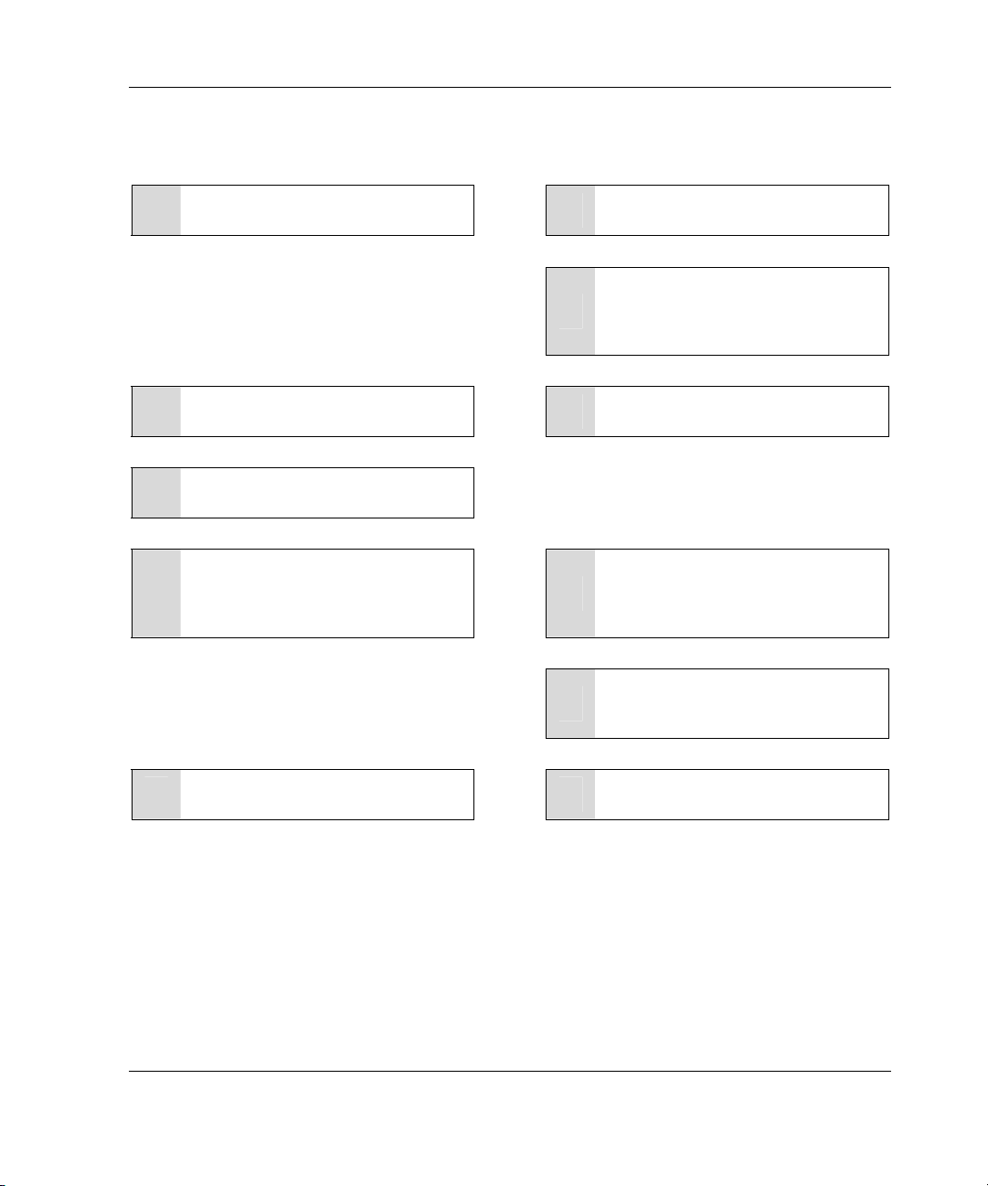
Symbols on Equipment
The following symbols may be placed on equipment to indicate the presence of
potentially hazardous conditions:
WARNING: This symbol, in conjunction with any of the following symbols,
indicates the presence of a potential hazard. The potential for injury exists if
warnings are not observed. Consult your documentation for specific details.
HP Smart Array 5300 Controller User Guide vii
Page 8
About This Guide
Weight in kg
Weight in lb
This symbol indicates the presence of hazardous energy circuits or electric
shock hazards. Refer all servicing to qualified personnel.
WARNING: To reduce the risk of injury from electric shock hazards, do not
open this enclosure. Refer all maintenance, upgrades, and servicing to
qualified personnel.
This symbol indicates the presence of electric shock hazards. The area
contains no user or field serviceable parts. Do not open for any reason.
WARNING: To reduce the risk of injury from electric shock hazards, do not
open this enclosure
This symbol on an RJ-45 receptacle indicates a network interface connection.
WARNING: To reduce the risk of electric shock, fire, or damage to the
equipment, do not plug telephone or telecommunications connectors into this
receptacle.
This symbol indicates the presence of a hot surface or hot component. If this
surface is contacted, the potential for injury exists.
WARNING: To reduce the risk of injury from a hot component, allow the
surface to cool before touching.
These symbols, on power supplies or systems, indicate that the
equipment is supplied by multiple sources of power.
WARNING: To reduce the risk of injury from electric shock,
remove all power cords to completely disconnect power from the
system.
This symbol indicates that the component exceeds the recommended
weight for one individual to handle safely.
WARNING: To reduce the risk of personal injury or damage to the
equipment, observe local occupational health and safety requirements
and guidelines for manual material handling.
viii HP Smart Array 5300 Controller User Guide
Page 9
Rack Stability
WARNING: To reduce the risk of personal injury or damage to the equipment,
be sure that:
• The leveling jacks are extended to the floor.
• The full weight of the rack rests on the leveling jacks.
• The stabilizing feet are attached to the rack if it is a single-rack installation.
• The racks are coupled together in multiple-rack installations.
• Only one component is extended at a time. A rack may become unstable if
more than one component is extended for any reason.
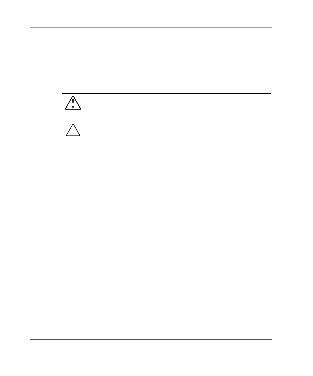
Symbols in Text
These symbols may be found in the text of this guide. They have the following
meanings.
WARNING: Text set off in this manner indicates that failure to follow directions
in the warning could result in bodily harm or loss of life.
About This Guide
CAUTION: Text set off in this manner indicates that failure to follow directions could
result in damage to equipment or loss of information.
IMPORTANT: Text set off in this manner presents essential information to explain a concept
or complete a task.
NOTE: Text set off in this manner presents additional information to emphasize or supplement
important points of the main text.
HP Smart Array 5300 Controller User Guide ix
Page 10

About This Guide
Related Documents
For additional information on the topics covered in this guide, refer to the following
documentation:
• HP Array Configuration Utility 6.0 User Guide (on the software CD provided
with the server, or downloadable from the HP website)
• HP Servers Troubleshooting Guide (on the Documentation CD for the server)
• HP ROM-Based Setup Utility User Guide (on the Documentation CD for the
server, or downloadable from the HP website)
Getting Help
If you have a problem and have exhausted the information in this guide, you can get
further information and other help in the following locations.
Technical Support
In North America, call the HP Technical Support Phone Center at 1-800-652-6672.
This service is available 24 hours a day, 7 days a week. For continuous quality
improvement, calls may be recorded or monitored. Outside North America, call the
nearest HP Technical Support Phone Center. Telephone numbers for worldwide
Technical Support Centers are listed on the HP website, www.hp.com.
Be sure to have the following information available before you call HP:
• Technical support registration number (if applicable)
• Product serial number
• Product model name and number
• Applicable error messages
• Add-on boards or hardware
• Third-party hardware or software
• Operating system type and revision level
x HP Smart Array 5300 Controller User Guide
Page 11

HP Website
The HP website has information on this product as well as the latest drivers and flash
ROM images. You can access the HP website at www.hp.com.
Authorized Reseller
For the name of your nearest authorized reseller:
• In the United States, call 1-800-345-1518.
• In Canada, call 1-800-263-5868.
• Elsewhere, see the HP website for locations and telephone numbers.
Reader’s Comments
HP welcomes your comments on this guide. Please send your comments and
suggestions by e-mail to ServerDocumentation@hp.com.
About This Guide
HP Smart Array 5300 Controller User Guide xi
Page 12
1
Board Components and Features
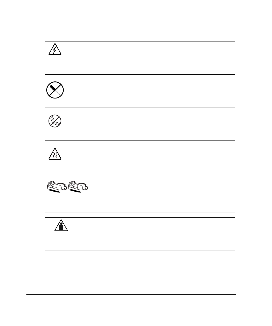
The HP Smart Array 5300 Series of controllers comprises two models, the 5302 and
the 5304. Model 5302 has two Wide Ultra3 SCSI channels and 128 MB of cache;
model 5304 has four Wide Ultra3 SCSI channels and 256 MB of cache. You can
upgrade the 5302 model to have four channels, 256 MB of cache, or both, by means
of the appropriate option kits.
1
3
2
Figure 1-1: Smart Array 5304 Controller
Item Description
1 Two internal 68-pin Wide SCSI connectors (port 1
nearer the bracket, port 2 nearer the board center)
2 Four external (VHDCI) connectors (ports 1 and 3
nearer the main board)
3 Array accelerator cache
HP Smart Array 5300 Controller User Guide 1-1
Page 13
Board Components and Features
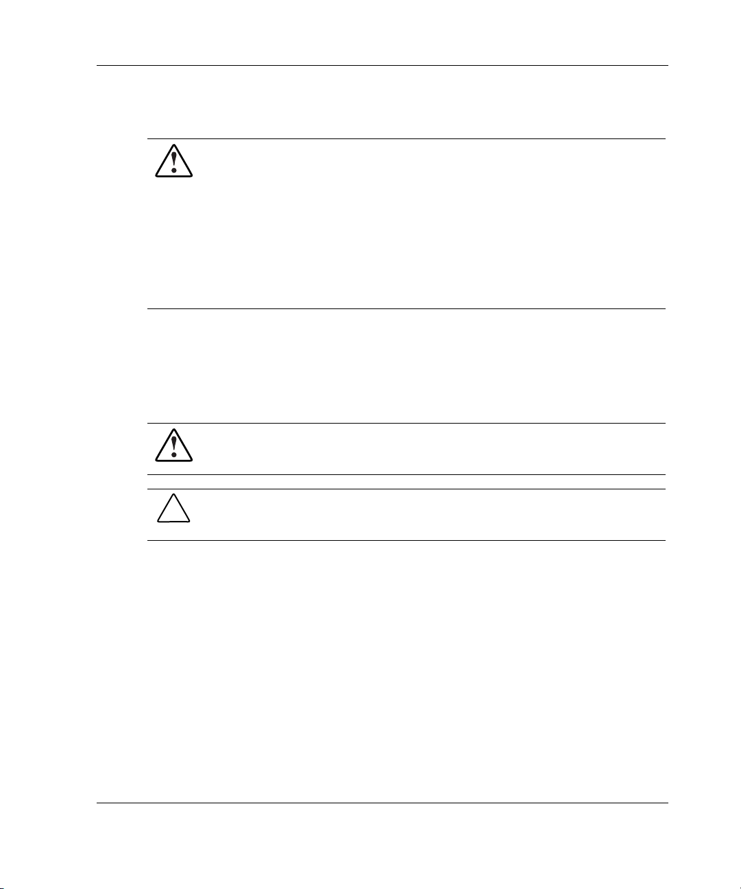
NOTE: On both controller models, ports 1 and 2 each have two connectors (one internal and
one external). However, only one connector can be used per port at any given time. Ports 3
and 4 (available on the 5304) can be used only for external drives.
1
2
Figure 1-2: Smart Array 5302 Controller
Item Description
1 Two internal 68-pin Wide SCSI connectors (port 1
nearer the bracket, port 2 nearer the board center)
2 Two external (VHDCI) connectors (port 1 nearer the
board)
3 Array accelerator cache
3
1-2 HP Smart Array 5300 Controller User Guide
Page 14

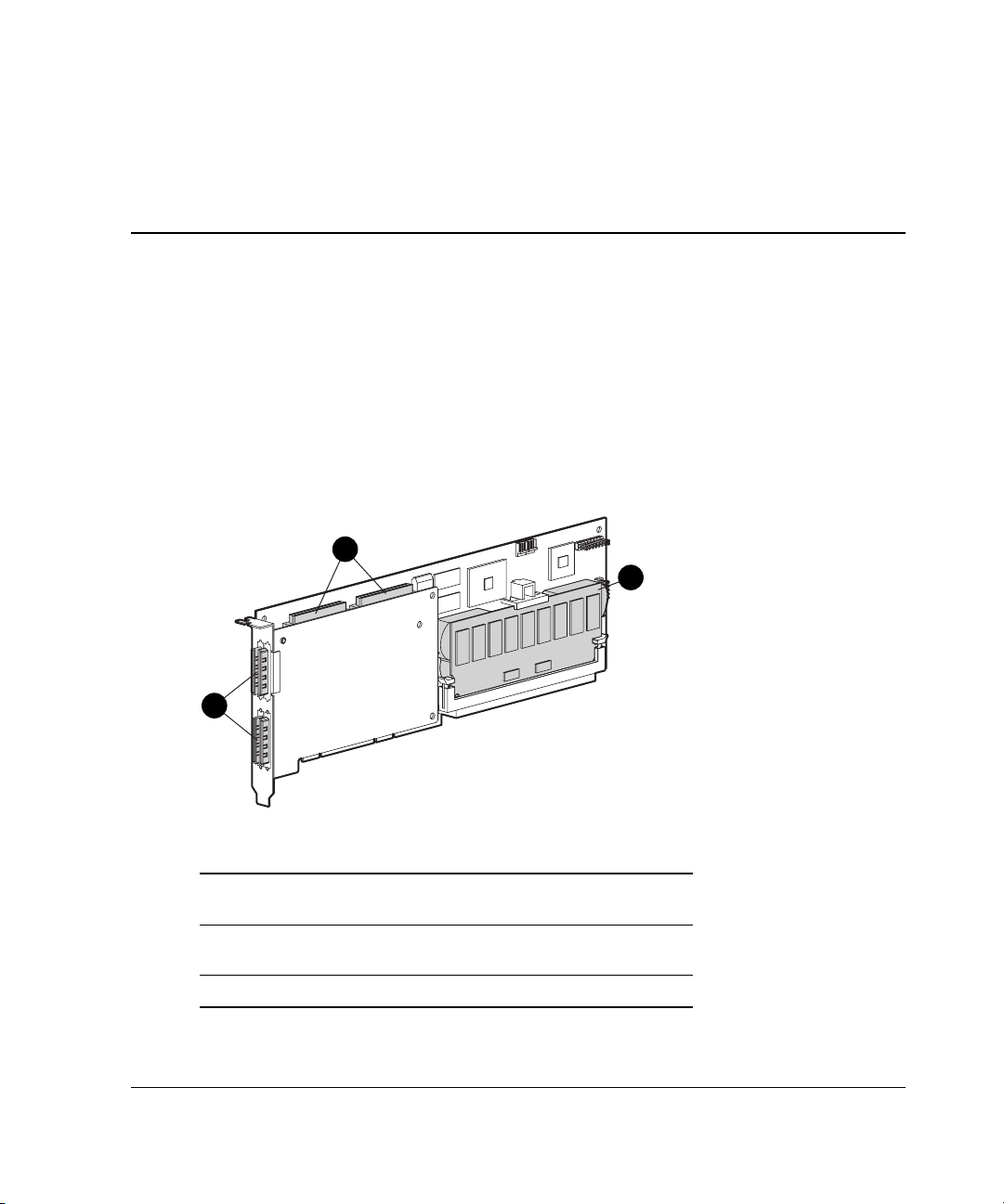
Figure 1-3: Two- to four-channel adapter upgrade
option
Board Components and Features
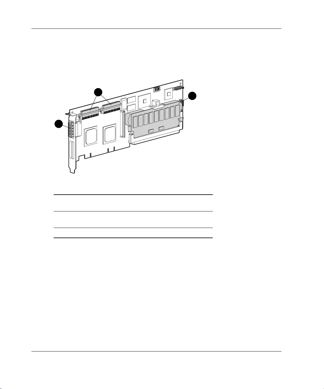
Figure 1-4: Array accelerator cache with batteries
For details of the controller board specifications, refer to Appendix C, “Controller
Specifications.”
HP Smart Array 5300 Controller User Guide 1-3
Page 15

Board Components and Features
Overview of Controller Features
•
Two or four Wide Ultra3 SCSI channels, supporting up to 56 drives (4 channels,
14 drives per channel)
•
Support for HP ProLiant and Intel
•
Support for Microsoft
®
Windows® 2000, Windows NT 4.0, Linux, Novell
NetWare 5.x, and NetWare 6 operating systems
•
Support for the Universal Hot Plug Tape Drive, with storage capacity up to 100
GB and LVD transfer rates up to 12 MB per second
•
Support for the StorageWorks SAN Access Module
•
Backward compatibility with Wide Ultra2 devices
•
Removable array accelerator
•
64-bit, 66-MHz PCI system interface
•
Other features supported:
— RAID fault-tolerance (0, 1+0, 5, ADG). Refer to Chapter 8, “Upgrading and
Replacing Options,” for instructions on enabling RAID ADG.
®
ItaniumTM Processor Family (IPF) Servers
— Online RAID migration between any two levels
— Online array capacity expansion
— Online logical drive capacity extension
— Hot-pluggable hard drives and tape drives
— Drive movement
— Adjustable stripe size
— Performance monitoring through Insight Manager
— S.M.A.R.T. hard drives
— Drive pre-failure notification
— Multiple online spares per array
— Tagged command queuing
— Background initialization
1-4 HP Smart Array 5300 Controller User Guide
Page 16

Board Components and Features
— Multiple logical drives per array
Overview of Array Accelerator Features
The array accelerator is a high performance, battery-backed, 100-MHz SDRAM
DIMM cache module.
Array controllers use cache to store read data from the hard drives. The system can
later access this read data. The controller firmware uses the read-ahead and most
recently used caching algorithms.
Array controllers also use cache to complete drive write operations more quickly.
This use of the cache has further performance benefits:
•
If the system requires data that still resides in write cache, the controller delivers
this data from the cache. This process is quicker than delivering the data from a
drive.
•
If the system writes new data to the same location, the controller overwrites the
cache contents. This eliminates a drive write operation.
•
If the system performs a RAID 1 procedure, the controller gets mirrored data
from the cache instead of from host memory.
•
If the system performs a RAID 5 procedure, the write cache collects enough data
blocks from several write accesses to carry out a full stripe write to the hard
drives. This operation eliminates the need to calculate and update parity
information each time that a data block is written to the drive.
With a battery-backed cache available, the array controller can complete the
following operations more rapidly:
•
Array capacity expansion—the expansion of a logical drive volume to include
more hard drives
•
Stripe size migration—the adjustment of the size of data blocks within a stripe,
done to improve performance
•
RAID level migration—the adjustment of RAID level to improve the fault
tolerance of the array
HP Smart Array 5300 Controller User Guide 1-5
Page 17

Board Components and Features
For each of these operations, data has to be reorganized among hard drives, and must
be saved to non-volatile storage during the operation. (For further details of these
operations, refer to Chapter 6, Appendix D, and Appendix E.) Without batterybacked cache, the data can only be stored at empty locations within the drive array,
so these operations cannot occur at all if the array is full.
If the array controller or server fails before cached data can be stored on the array, the
array accelerator and its integrated batteries may be removed from one array
controller and installed on another controller of the same type. Any data in the array
accelerator that has not been written to the hard drive will be transferred to the other
array controller.
Other features of the array accelerator include:
•
Cache capacity of 96-MB or 224-MB (32 MB of the cache is used for transfer
buffer)
•
Adjustable read/write ratio (usually set during array configuration as described in
Chapter 6, “Configuring an Array,” but can be changed at any time)
•
Error checking and correcting (ECC) memory, providing single-bit data
correction
Sometimes, the Automatic Performance Tuning feature disables the array accelerator.
You can also disable the array accelerator manually through the Array Configuration
Utility (refer to Chapter 6, “Configuring an Array,” for details).
Batteries
The array accelerator cache has two rechargeable and replaceable NiMH battery
packs. If the array accelerator is removed from the array controller, the battery packs
maintain any cached data on the array accelerator for up to four continuous days.
1-6 HP Smart Array 5300 Controller User Guide
Page 18
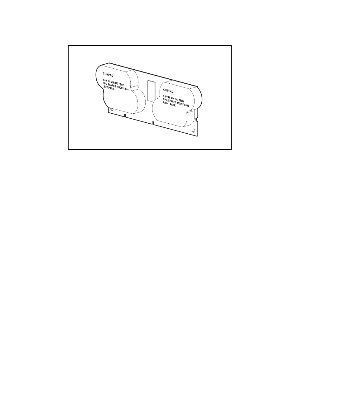
Board Components and Features
Figure 1-5: Battery packs
This data protection (and the time limit) also applies if an equipment failure or power
outage occurs. When power is restored to the system, an initialization process writes
the preserved data to the hard drives.
The batteries are continuously recharged using a trickle-charging process whenever
the system power is on. Under normal operating conditions, a battery pack lasts for
three years before replacement is necessary.
IMPORTANT: The batteries on a new array controller may have a low charge when the
controller board is first installed. In this case, a Power-On Self-Test (POST) message is
displayed when the server is powered up, indicating that the array accelerator is temporarily
disabled. No action is required on your part, since the internal circuitry automatically recharges
the batteries and enables the cache. The recharge process takes less than four hours. The
array controller will function properly during this time, although without the performance
advantage of the array accelerator. When the batteries are charged to an acceptable capacity,
the array accelerator is automatically enabled.
For battery replacement instructions, refer to Chapter 8, “Upgrading and Replacing
Options.”
HP Smart Array 5300 Controller User Guide 1-7
Page 19

Board Components and Features
PCI System Interface
Smart Array 5300 controllers interface to the server through a high-performance
64-bit PCI bus that:
•
Runs at 66 MHz
•
Provides a high-speed path (up to 528 MB/s) between the system board and the
controller
•
Includes two parity protection signals
The Smart Array 5300 Controller is a PCI Bus Master device conforming to Rev. 2.2
of the PCI Local Bus Specification. As a bus master device, it takes control of the
PCI bus during high-speed transfers, freeing the system processor to handle
application processing or other types of tasks.
For maximum performance, HP recommends that you use only 66-MHz devices on
any given 66-MHz PCI bus. Combining 66-MHz and 33-MHz devices on a PCI bus
will decrease the overall bandwidth to 33-MHz speeds.
SCSI Support
The Smart Array 5300 Controller supports drives that conform to Wide Ultra3 and
Wide Ultra2 standards. Although Wide Ultra2 devices operate at a different
maximum speed from Wide Ultra3 devices, operating speeds are unaffected if they
are connected to the same SCSI bus because they both use low voltage differential
(LVD) signaling.
Fault Management Features
The array controller and the network operating system support several fault
management and data reliability features that minimize the impact of hard drive
defects on your system.
1-8 HP Smart Array 5300 Controller User Guide
Page 20

Board Components and Features
• Auto-Reliability Monitoring (ARM) is a background process that scans hard
drives for bad sectors in fault-tolerant logical drives. ARM also verifies the
consistency of parity data in logical drives that are using RAID 5 or RAID ADG.
This process assures that you can recover all data successfully if a drive failure
occurs in the future. ARM operates only when you select a fault-tolerant
configuration (RAID 1 or higher).
•
Dynamic sector repair by the controller automatically remaps any sectors that
have media faults (detected either during normal operation or by auto reliability
monitoring).
•
S.M.A.R.T. is an industry-standard diagnostic and failure-prediction feature of
hard drives, developed in collaboration with the hard drive industry. It monitors
several factors that can be used to predict imminent hard drive failure due to
mechanical causes. Such factors include the condition of the read/write head, the
seek error rate, and the spin-up time. When a threshold value is exceeded for one
of these factors, the drive sends an alert that failure is imminent. Thus, the user
can back up data and replace the drive before drive failure occurs.
NOTE: An online spare does not become active and start rebuilding when the imminent
failure alert is sent, because the degraded drive has not actually failed yet and is still
online. The online spare is activated only after a drive in the array has failed.
•
Drive failure alert features cause an alert message to be displayed on the
system monitor when drive failure occurs. Different server models use different
messages for different situations. These messages are described in your server
documentation.
•
Interim data recovery occurs if a drive fails in fault-tolerant configurations
(RAID 1 or higher). In this situation, the system will still process I/O requests,
but at a reduced performance level. Replace the failed drive as soon as possible
to restore performance and full fault tolerance for that logical drive. For example,
in a RAID 5 configuration, if another hard drive fails before data has been
rebuilt, the logical volume will fail and data will be lost. For more information
about recovering from drive failure, refer to Appendix E, “Hard Drive
Installation and Replacement.”
•
POST or the Array Diagnostics Utility will also reveal imminent drive failure.
HP Smart Array 5300 Controller User Guide 1-9
Page 21

Board Components and Features
• Recovery ROM is a redundancy feature that ensures continuous system
availability by providing a backup ROM. This feature protects against corruption
of a ROM image (caused, for example, by power fluctuation during ROM
upgrade). If corruption occurs, the server automatically restarts using the
remaining good copy of the ROM image.
When you upgrade the ROM, the inactive image (the one not being used by the
system) is upgraded. There is not normally any noticeable difference in
operation. When you use Recovery ROM for the first time, however, both ROM
images are upgraded, causing a boot delay of about 60 seconds.
Other options, such as Insight Manager, provide additional drive failure features.
Refer to your authorized reseller for more information about these products.
1-10 HP Smart Array 5300 Controller User Guide
Page 22

Installation Overview
The details of the steps required to install the controller depend on the server model
and whether the server is a new or existing one. The following flowcharts summarize
the installation procedures for the most common scenarios.
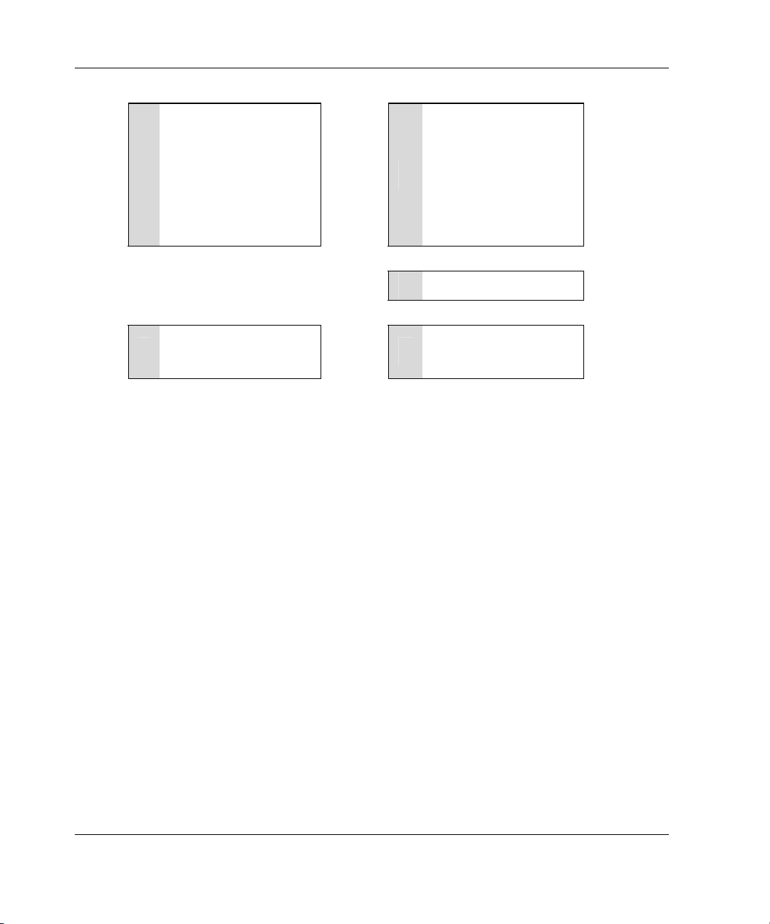
Procedure for a New, Autoconfigurable System
Some new HP ProLiant server models self-configure when they are powered up for
the first time. During the autoconfiguration process, the system language is set to
English by default, and Microsoft Windows 2000 is selected as the default operating
system. (However, you must still install the operating system. This is done later in
the overall controller installation procedure.) If you want to use a different system
language or operating system, you can press the F9 key at any time. This action
opens RBSU, which allows you to manually configure the server.
2
Also, if the server has fewer than seven physical drives installed, ORCA
automatically configures the drives into an array, builds a logical drive, and sets a
RAID level suitable for the number of drives.
To determine if your server is autoconfigurable, refer to the server-specific setup and
installation guide.
IMPORTANT: Do not power up the server until the hardware configuration is satisfactory, as
described in the procedure given in this section.
HP Smart Array 5300 Controller User Guide 2-1
Page 23
Installation Overview
Install the controller
hardware (Chapter 3), if
1
it is not pre-installed.
. . . . . . .
Install the physical
drives if necessary. (The
number of drives
present determines the
RAID level that is
2
autoconfigured. For
details, refer to the
server-specific setup
and installation guide
Create and format
additional logical drives
5
if desired (Chapter 6).
. . . . . . .
Power up the server.
3
Install the operating
system and
4
applications.
:
:
Figure 2-1: Controller installation in a new, autoconfigurable system
2-2 HP Smart Array 5300 Controller User Guide
Page 24
Installation Overview
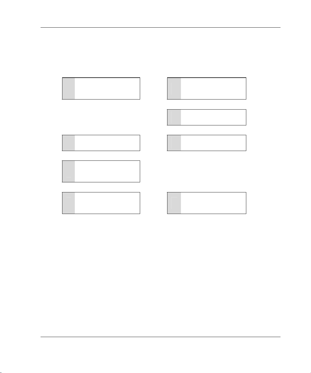
Procedure for a New, Non-autoconfigurable System
ProLiant Servers
Install the controller
hardware (Chapter 3), if
1
it is not pre-installed.
. . . . . . .
Update the system
2
firmware (Chapter 4).
Set the boot controller
5
(Chapter 5).
Create at least one
logical drive and format
6
it (Chapter 6).
Install the operating
system and device
7
drivers (Chapter 7).
Figure 2-2: Controller installation in a new, non-autoconfigurable system
:
:
. . . . . . .
. . . . . . .
Update the controller
3
firmware (Chapter 4).
Configure the system
4
(Chapter 5).
Create and format
additional logical drives
8
if desired (Chapter 6).
:
:
HP Smart Array 5300 Controller User Guide 2-3
Page 25
Installation Overview
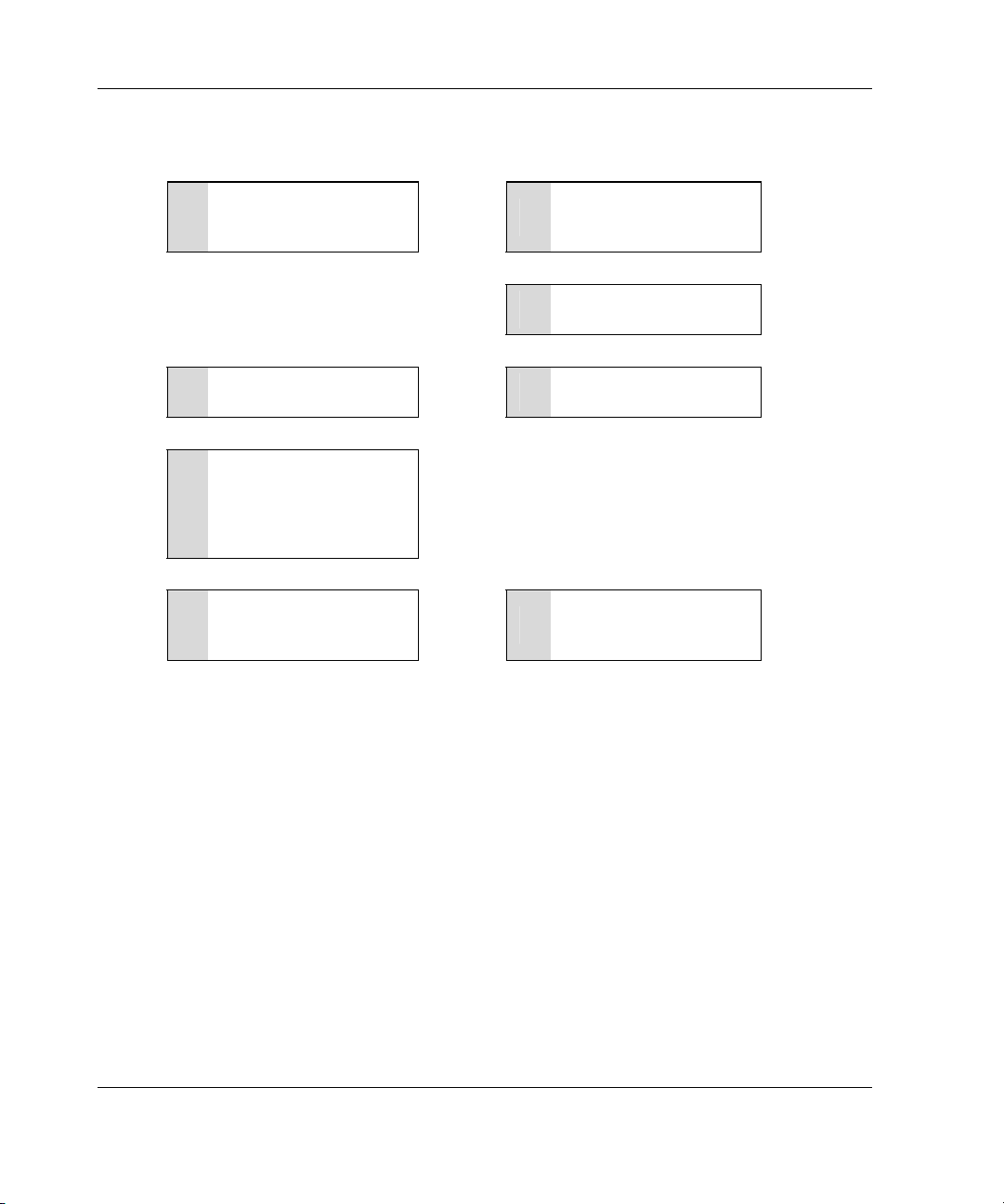
Intel IPF Servers
Install the controller
hardware (Chapter 3), if
1
it is not pre-installed.
. . . . . . .
Configure an array
2
(Chapter 6).
Install the operating
5
system (Chapter 7).
If you are installing
additional Smart Array
controllers, install the
6
device drivers
(Chapter 7).
Install the management
7
agents (Chapter 7).
:
:
. . . . . . .
. . . . . . .
Configure the system
3
(Chapter 5).
Update the controller
4
firmware (Chapter 4)
Create and format
additional logical drives
8
if desired (Chapter 6).
:
:
Figure 2-3: Controller installation in a new, non-autoconfigurable system
2-4 HP Smart Array 5300 Controller User Guide
Page 26
Procedure for a Preconfigured System
Back up data (required if migrating
1
from a non-array controller).
- - - - -
Update the system firmware
2
(Chapter 4).
Installation Overview
Set the controller order (Chapter 5).
5
Update the controller firmware
6
(Chapter 4).
If using the System Configuration
Utility, update the system partition
7
(Chapter 4), and then check the
controller order (Chapter 5).
If migrating from a non-array
11
controller, restore data from backup.
:
:
- - - - -
- - - - -
- - - - -
If the controller is to be the boot
device, install the device driver for
3
your operating system (Chapter 7).
Otherwise, continue with step 4.
Install the controller hardware
4
(Chapter 3).
If the controller is not to be the boot
device, install the device driver for
8
your operating system (Chapter 7).
Update Insight Manager Agents if
new versions are available
9
(Chapter 7).
Create and format logical drives as
10
desired (Chapter 6).
:
:
:
:
Figure 2-4: Controller installation in a preconfigured
system
HP Smart Array 5300 Controller User Guide 2-5
Page 27

Preparing the Server
Before installing the controller in the server, back up all data. This step is mandatory
if you are moving non-arrayed SCSI drives to a Smart Array controller, because data
is not preserved during a move between array controllers and non-array controllers.
WARNING: To reduce the risk of personal injury or damage to the equipment,
consult the safety information and user documentation provided with your
computer before attempting the installation.
Many computers are capable of producing energy levels that are considered
hazardous. These computers are intended to be serviced by qualified
personnel trained to deal with those hazards. Do not remove enclosures or
attempt to bypass any interlocks that may be provided for the purpose of
removing these hazardous conditions.
3
Installing the Hardware
If your server supports hot-pluggable devices, go directly to the section, “Installing
the Smart Array Controller.”
To prepare a server that does not support hot-pluggable devices:
1. Close all applications.
2. Power down the server.
CAUTION: In systems using external data storage, be sure that the server is the
first unit powered down and the last unit to be powered back up. Doing this
ensures that the system will not erroneously mark the drives as “failed.”
3. Power down any peripheral devices that are attached to the server.
HP Smart Array 5300 Controller User Guide 3-1
Page 28
Installing the Hardware
4. Unplug the AC power cord from the outlet, and then from the server.
IMPORTANT: If you will be replacing an existing Smart Array controller with a Smart
Array 5300 controller, see the “External Cabling for HP Servers” section to determine the
external cabling requirements.
5. Disconnect any peripheral devices from the server.
WARNING: To reduce the risk of personal injury from hot surfaces, allow
the internal system components and hot-plug hard drives to cool before
touching them.
CAUTION: Electrostatic discharge (ESD) can damage electronic components.
Be sure that you are properly grounded before continuing the installation
procedure. Refer to Appendix B, “Electrostatic Discharge,” for ESD information.
Installing the Smart Array Controller
1. Remove or open the access panel.
2. Select an available 66-MHz PCI slot. Slots that use a 64-bit interface may
provide higher performance.
NOTE: In IPF servers, the ID number of the slot in which you insert the controller
determines the boot controller order. Follow the recommendations in the server-specific
documentation to obtain the required controller order.
3. Remove the slot cover or open the hot-plug latch. Save the retaining screw, if one
is present.
4. Slide the controller board along the slot alignment guide.
3-2 HP Smart Array 5300 Controller User Guide
Page 29

Installing the Hardware
Figure 3-1: Installing a Smart Array 5300 Controller
NOTE: Your server may look slightly different from the one illustrated.
5. Press the controller board firmly into the slot so that the contacts on the board
edge are properly seated in the system board connector.
6. Secure the board in place with the hot-plug latch or retaining screw.
7. Continue by following the instructions given in “Connecting the Cables.”
Connecting the Cables
Each port on the controller supports up to 14 drives. Ports 1 and 2 each have two
SCSI connectors, one for external storage units and one for internal hard drives in the
server. The two connectors for a given port cannot be used simultaneously. Ports 3
and 4 (present on the 5304 model, and also on the 5302 model with an attached 2- to
4-channel adapter) are only for external storage units.
Peripherals attached to any of the connectors must have a unique SCSI ID value in
the range of 0 to 15 (except ID 7, which is reserved for controller use). The SCSI ID
value determines the priority given to the device when it attempts to use the SCSI
bus.
HP Smart Array 5300 Controller User Guide 3-3
Page 30

Installing the Hardware
On HP and Compaq-branded products that support hot-pluggable drives, the SCSI
IDs for peripherals are automatically set. For non-hot-pluggable devices, the IDs
must be set manually by using switches or jumpers on the device itself.
IMPORTANT: When replacing an existing Smart Array controller with a Smart Array 5300
controller without reconfiguring the arrays, all of the drives should be connected exactly as
they were on the old controller (port 1 to port 1, controller 1 to controller 1, and so on).
SCSI buses require termination on both ends to prevent signal degradation. In HP and
ProLiant servers and IPF servers, however, the controller, SCSI cable, and backplane
already provide this termination.
Internal Cabling for HP Servers
1. If the device is not hot pluggable, power down the system.
2. Install drives in the removable media bays on the server. Drives that are to be
grouped in the same array should have the same capacity.
For detailed drive installation instructions, consult the documentation that
accompanied your drives.
The exact procedure from this point depends upon whether the device is hot
pluggable.
— If the drives are hot pluggable, go to step 3.
— If the drives are not hot pluggable, go to step 4.
3. Attach the internal point-to-point SCSI cable (provided with your server) from an
internal port of the controller to the hot-plug drive cage.
For duplex drive cage options, use both internal ports.
The hot-pluggable drives are now ready to use.
4. For each SCSI bus, manually set the SCSI ID on each drive to a unique value in
the range of 0 to 15, except 7 (which is reserved for controller use). For detailed
instructions, consult the documentation that is provided with the drive.
5. Attach the multi-device SCSI cable from the internal port 1 or port 2 of the Smart
Array controller to the non-hot-pluggable hard drives.
6. Replace the access panel and secure it with the thumbscrews, as required.
3-4 HP Smart Array 5300 Controller User Guide
Page 31

CAUTION: Do not operate the server with the access panel removed for
extended periods of time. This precaution protects thermally sensitive
components by ensuring the proper airflow through the server and minimizes
personal contact with hazardous energy levels.
For additional information about drive installation, see Appendix E, “Hard Drive
Installation and Replacement.”
External Cabling for HP Servers
All HP and Compaq-branded Storage Enclosure models include external SCSI
cables. Check the connector type on your storage device to identify the cable type
needed. See Figure 3-2 and Table 3-1 for details.
Installing the Hardware
2
1
3
4
Figure 3-2: Identifying SCSI cable connectors
Item Description
1 External 68-pin Wide
2 External offset VHDCI
3 Internal 50-pin narrow
4 Internal 68-pin Wide
HP Smart Array 5300 Controller User Guide 3-5
Page 32

Installing the Hardware
Up to four SCSI ports may be available for connection to external storage devices
depending on whether the 2- to 4-channel adapter is attached and whether internal
drives are connected to the array controller.
7. On the rear of the server, connect the cable to the VHDCI connector on the Smart
Array controller, and then tighten the lock screws on the cable connector.
IMPORTANT: Offset VHDCI cables must be used with the Smart Array 5300 controller.
Early versions of the VHDCI cables do not accommodate side-by-side connection of the
cables to the Smart Array 5300 controller. If your storage enclosure did not include the
Offset VHDCI cables, you may need to order these. See Table 4-1 for part numbers.
NOTE: Do not use a port externally if it is already being used internally.
8. Attach the other end of the cable to the storage enclosure, and then tighten the
lock screws on the cable connector.
3-6 HP Smart Array 5300 Controller User Guide
Page 33

Installing the Hardware
SCSI Cable Part Numbers
Table 3-1: Internal and External SCSI Cable Part Numbers
Cable type* Length Option kit number Cable assembly number
External cables
VHDCI to VHDCI
(all server models)
VHDCI to Wide
(ProLiant servers)
Internal cables
ProLiant, multi-device -- 166389-B21 148785-001
1.8 m/6 ft 341174-B21 313374-001
3.6 m/12 ft
7.2 m/24 ft 164604-B21 313374-004
11.7 m/39 ft 150214-B21 313374-005
1.8 m/6 ft
3.6 m/12 ft 341177-B21 313375-002
341175-B21 313374-002
341176-B21 313375-001
IPF (rx5670)
• Single port
• Dual port
IPF (rx2600)
• Single port
• Dual port
*If additional cables are required, order by the option kit number.
18 cm
20 cm
49 cm
58 cm
A9828A
--
--
A9827A
--
--
--
A9828-63001
A9828-63002
--
A7231-63024
A7231-63025
HP Smart Array 5300 Controller User Guide 3-7
Page 34

4
Updating the Firmware
To update the firmware, you can use the Smart Components that are available on the
HP website (http://www.hp.com/support).
1. Locate the Smart Component for the operating system and controller that the
server is using.
2. Follow the instructions for installing the component on the server. These
instructions are given on the same Web page as the components.
3. Follow the additional instructions that describe how to use the component to
flash the ROM. These instructions are provided with the component itself.
An alternative method for updating the firmware on ProLiant servers is to use the
software CD that is supplied in the controller kit. However, the Smart Components
may contain more recent firmware upgrade files than those given on the CD. Before
using the CD, check the Smart Components on the website to see whether newer
versions of the firmware upgrade files are available.
ProLiant Servers
IMPORTANT: If you are updating the firmware on a system that was configured using SCU,
you must update the system partition (refer to “Using SCU” in Chapter 5, “Configuring the
Server”) immediately after you have finished updating the firmware.
HP Smart Array 5300 Controller User Guide 4-1
Page 35

Updating the Firmware
Using the SmartStart CD
1. Insert the CD into the CD-ROM drive of the server.
If you want to update the firmware with the server offline, restart the server and
wait for controller initialization to finish.
2. Select the language and keyboard that you want to use.
The license agreement (EULA) screen is displayed.
3. Click Agree.
The MyProLiant Server screen is displayed.
4. Click the Maintenance tab.
5. Click ROM Update Utility.
6. Select Express or Custom mode, and follow the on-screen prompts and
instructions to update the firmware on the system and the controller.
7. If you want to use Smart Components to apply the most current updates, refer to
the “Using the Smart Components with a CD” section in this chapter.
8. Restart the server for the updates to take effect.
Using the Support Software CD
1. Insert the CD into the CD-ROM drive of the server.
If you want to update the firmware with the server offline, restart the server and
wait for controller initialization to finish.
The license agreement (EULA) screen is displayed.
2. Click Agree.
The Home screen is displayed.
3. Click ROM Update Utility.
4. Select Express or Custom mode, and follow the on-screen prompts and
instructions to update the firmware on the system and the controller.
4-2 HP Smart Array 5300 Controller User Guide
Page 36

5. If you want to use Smart Components to apply the most current updates, refer to
the “Using the Smart Components with a CD” section in this chapter.
6. Restart the server for the updates to take effect.
Using the Smart Components with a CD
1. Return to the ROM Update Utility screen and click the Supplemental Disk tab.
The URL from which you can download the Smart Components is provided at
the top of the screen.
2. Visit the Smart Components Web page.
a. Locate the most recent Smart Component for the controller that the server is
using.
b. Download the component to diskette as described on the Web page.
c. If the component was downloaded using a different computer, insert the
diskette into the diskette drive of that server.
3. Click the Use Disk button.
The firmware update is copied (but not yet installed) to your drive, and the Smart
Component ID number is given on the Supplemental Disk screen.
Updating the Firmware
4. Click the Updates tab. If an update is necessary, the new firmware needed is
listed here.
5. Click the Update Now button.
6. When the update is complete, click the Results tab to view a summary of the
flashed firmware.
7. To update firmware for more components:
a. Return to the Supplemental Disk screen.
b. Click the Rescan button to refresh the screen view.
c. Repeat steps 2 through 5.
8. Restart the server for the updates to take effect.
HP Smart Array 5300 Controller User Guide 4-3
Page 37

Updating the Firmware
IPF Servers
If the IPF server uses a supported Microsoft Windows operating system, an
alternative method to the Smart Components for updating the firmware is to use the
DVD from the controller kit, as follows:
1. On the main menu of the EFI-based configuration utility on the DVD, select
Maintain Firmware.
2. Select the firmware that you want to update.
3. Follow the on-screen prompts and instructions to complete the firmware updates.
4. Reboot the server for the firmware updates to take effect.
For more information about IPF servers, for technical support, or for updated
firmware, drivers, and utilities, refer to the HP website
http://www.hp.com/support/itaniumservers
(
).
4-4 HP Smart Array 5300 Controller User Guide
Page 38

ProLiant Servers
After installing the controller hardware and updating the firmware, configure the
server by using either RBSU or SCU. (A brief description of the procedure is given
in this section. For more information, refer to the HP ROM-Based Setup Utility User
Using RBSU
Guide or the server setup and installation guide.)
5
Configuring the Server
RBSU is a system configuration utility that is embedded in the system ROM. It is
customized for the server on which it is installed.
CAUTION: Not all servers support RBSU. Do not flash an RBSU-ROM image onto a
server that is already configured with SCU unless the update instructions specifically
state that upgrading from SCU to RBSU is supported. If the upgrade is not
supported, the consequences of upgrading are unpredictable, and you may lose
data.
To use RBSU:
1. Power up the server.
2. Press the F9 key when prompted during system startup.
The main RBSU screen is displayed.
3. Configure the system. (For more information, refer to the ROM-Based Setup
Utility User Guide.)
HP Smart Array 5300 Controller User Guide 5-1
Page 39

Configuring the Server
4. Select Boot Controller Order on the main RBSU screen and follow the on-
screen prompts to set the boot controller.
5. When you have finished using RBSU, press the Esc key, and then press the F10
key to confirm that you want to exit.
The server reboots with the new configuration.
Using SCU
If you updated the firmware in a used system that was not configured using RBSU,
you must use the System Configuration Utility (SCU) to update the system partition.
1. Locate the page on the HP website (http://www.hp.com/support
SCU, and then follow the on-screen instructions to create four SCU diskettes.
2. Insert SCU diskette #1 into the server diskette drive.
3. Restart the system.
4. Select System Configuration Utility from the menu or list of icons that is
displayed.
5. Follow the on-screen instructions to update or create and populate a system
partition.
6. Exit from SCU. If the server does not reboot or a CD error message is displayed,
press the Ctrl+Alt+Del keys to reboot the server manually.
When you have finished using SCU to configure the system, use ORCA immediately
afterward to confirm that the controller order is unchanged, as follows:
1. Reboot the server. The POST sequence begins, and an ORCA prompt message is
briefly displayed.
) that contains
2. Press the F8 key to start ORCA.
NOTE: The ORCA prompt is displayed for only a few seconds. If you do not press the F8
key during this time, you must restart the server to obtain the prompt again.
3. On the Main Menu screen, select Select as Boot Controller.
4. Follow the remaining prompts to set the currently selected controller as the boot
controller for the system.
5-2 HP Smart Array 5300 Controller User Guide
Page 40

If you want to use ORCA to create logical drives, you do not need to exit the utility at
this point. Continue as described in Chapter 6, “Configuring an Array.”
IPF Servers
When you have finished configuring an array, you can create partitions on the
system. For IPF servers that use a supported Microsoft Windows operating system,
you can use the DVD that is supplied in the controller kit.
1. Insert the DVD into the DVD-ROM drive.
2. Follow the on-screen prompts and instructions to create an EFI system partition.
3. When creation of the system partition is complete, follow the on-screen prompts
and instructions to create an HP service partition.
When creation of the HP service partition is complete, you are ready to install the
operating system. Refer to Chapter 7, “Installing the Device Drivers.”
Configuring the Server
HP Smart Array 5300 Controller User Guide 5-3
Page 41

6
Configuring an Array
HP provides two utilities for manually configuring an array on a Smart Array
controller:
•
Array Configuration Utility (ACU)—A versatile, browser-based utility that
provides maximum control over configuration parameters
•
Option ROM Configuration for Arrays (ORCA)—A simple ROM-based
configuration utility that runs on all operating systems
Whichever utility you use, the following limitations apply:
•
For the most efficient use of drive space, do not mix drives of different capacity
within the same array. The configuration utility treats all physical drives in an
array as if they have the same capacity as the smallest drive in the array. The
excess capacity of any larger drives is wasted because it is unavailable for data
storage.
•
The probability that an array will experience a drive failure increases with the
number of physical drives in the array. If you configure a logical drive with
RAID 5, keep the probability of failure low by using no more than 14 physical
drives in the array (for details, refer to Appendix F, “Probability of Logical Drive
Failure”).
For conceptual information about arrays, logical drives, and fault tolerance methods,
refer to Appendix D, “Drive Arrays and Fault Tolerance.”
NOTE: To copy a particular array configuration to several other servers on the same network,
use the Array Configuration Replicator (ACR) utility or the scripting capability of ACU. ACR is
provided in the SmartStart Scripting Toolkit, available on the HP website
(http://www.hp.com/servers/sstoolkit
HP Smart Array 5300 Controller User Guide 6-1
).
Page 42

Configuring an Array
Table 6-1: Comparison of Utilities for Configuring an Array
Feature ACU* ORCA*
Uses a graphical interface y n
Available in languages other than English y n
Executable at any time y n
Available on CD y n
Uses a wizard to suggest the optimum configuration for an unconfigured
controller
Describes configuration errors y n
Supports these operating systems:
Windows Server 2003 y y
Windows 2000 y y
Windows NT y y
Novell NetWare y† y
Linux y‡ y
Allows these procedures:
Creation and deletion of arrays and logical drives y y
Assignment of RAID level y y
Sharing of spare drives among several arrays y n
Assignment of multiple spare drives per array y n
Setting of stripe size y n
Migration of RAID level or stripe size y n
Configuration of controller settings y n
Expansion of an array y n
y n
continued
6-2 HP Smart Array 5300 Controller User Guide
Page 43

Configuring an Array
Table 6-1: Comparison of Utilities for Configuring an Array continued
Creation of multiple logical drives per array y n
Setting of boot controller n y
*y = feature is supported; n = feature is not supported
†
NetWare can use ACU only when the system is offline.
‡
IPF systems cannot run ACU in a Linux environment.
Using ACU
For detailed information about using ACU, refer to the HP Array Configuration
Utility User Guide. This document is available on the Controller Products
Documentation CD that is provided in the controller kit.
NOTE: IPF servers that are running the Linux operating system cannot use ACU. In this case,
use ORCA.
Using ORCA
When a server is powered up, part of the startup sequence is the Power-On Self-Test
(POST). Any array controllers that are in the system are initialized while POST is
running. If the array controller supports ORCA, POST temporarily halts, and an
ORCA prompt message is displayed for about five seconds. (If ORCA is not
supported, the prompt message is not displayed, and the system continues with the
startup sequence.)
While the prompt is displayed, press the F8 key to start ORCA. The ORCA main
menu is displayed, allowing you to create, view, or delete a logical drive. (On a
ProLiant system, you can also use ORCA to set the currently selected controller as
the boot controller.)
HP Smart Array 5300 Controller User Guide 6-3
Page 44

Configuring an Array
Figure 6-1: ORCA main menu screen
To create a logical drive:
1. Select Create Logical Drive.
The screen displays a list of all available (unconfigured) physical drives and the
valid RAID options for the system.
2. Use the arrow keys, space bar, and tab key to navigate around the screen and set
up the logical drive, including an online spare drive if one is required.
NOTE: You cannot use ORCA to configure one spare drive to be shared among several
arrays. Only ACU allows you to configure shared spare drives.
While configuring the logical drive, one of the settings allows you to use either 4
GB or 8 GB as the maximum boot drive size. Selecting 8 GB allows a larger boot
partition for operating systems such as Windows NT 4.0 that use cylinders,
heads, and sectors of a physical drive to determine the drive size. The larger boot
drive size also lets you increase the size of the logical drive at some later time.
However, logical drive performance is likely to decrease if the larger boot drive
size is enabled.
3. Press the Enter key to accept the settings.
6-4 HP Smart Array 5300 Controller User Guide
Page 45

Configuring an Array
4. Press the F8 key to confirm the settings and save the new configuration.
After several seconds, the Configuration Saved screen is displayed.
5. Press the Enter key to continue.
You can now create another logical drive by repeating the previous steps.
NOTE: Newly created logical drives are invisible to the operating system. To make new
logical drives available for data storage, format them using the instructions given in the
operating system documentation.
HP Smart Array 5300 Controller User Guide 6-5
Page 46

ProLiant Servers
Device Drivers
The drivers for the controller are located on the Support Software CD or the
SmartStart CD that is provided in the controller kit. Updates are posted to the HP
website (http://www.hp.com/support).
7
Installing the Device Drivers and
Management Agents
Using the Support Software CD: Instructions for installing the drivers from the
Support Software CD are given in the leaflet that is supplied with the CD. Note that
the exact procedure depends on whether the server is new or already contains the
operating system and user data.
Using the SmartStart CD: If you use the Assisted Installation path feature of
SmartStart to install the operating system on a new server, the drivers are
automatically installed at the same time.
You can also use SmartStart to update the drivers manually on older systems. For
HP Smart Array 5300 Controller User Guide 7-1
more information, refer to the SmartStart documentation.
Page 47

Installing the Device Drivers and Management Agents
Management Agents
If you use the Assisted Installation path feature of SmartStart to install the operating
system on a new server, the Management Agents are automatically installed at the
same time.
You can update the Management Agents on older servers by using the latest versions
of the agents from one of these sources:
•
The Management CD, obtainable from your local HP reseller or authorized
service provider
•
The SmartStart CD
•
The HP website (http://www.hp.com/servers/manage
For the procedure to update the agents, refer to the documentation on the
Management CD or on the HP website.
If the new agents do not function correctly, you may also need to update
Insight Manager. The latest versions of Insight Manager are also available for
download at the HP website.
IPF Servers
Operating System
Device Drivers
For definitive instructions, refer to the operating system documentation.
If you want to install additional Smart Array controllers in the server, you also need
to install device drivers. For servers that use a supported Microsoft Windows
operating system, these drivers are present on the DVD that is provided in the
controller kit.
IMPORTANT: If you are configuring a new server, install the operating system before
installing the device driver.
)
7-2 HP Smart Array 5300 Controller User Guide
Page 48

Installing the Device Drivers and Management Agents
1. Power down the server and disconnect the power cords.
2. Install the new controller and connect it to storage devices.
3. Power up the server.
The operating system recognizes the controller and launches the Found New
Hardware wizard.
4. In the Files Needed dialog box, select the option to automatically search for the
driver.
5. When the driver installation process is complete, click Finish to exit the wizard,
and then click Yes to confirm that you want to reboot the server.
6. Repeat the previous steps for each new controller to be installed in the server.
Management Agents
IPF servers that use a supported Windows operating system can install the
Management Agents from the DVD that is supplied in the controller kit.
1. Power up the server.
2. When the operating system is running, insert the DVD into the DVD-ROM drive.
3. The Resource Mode Utility (RMU) opens.
4. Select the server, and then click Software and Drivers.
5. Click HP Server Agents.
6. Double-click the setup.exe file.
7. Follow the on-screen prompts and instructions to install or update the
Management Agents.
8. If SNMP is not installed on the system, install it from the HP Server Agents
screen. (Alternatively, you can install it from the Windows distribution CD.)
IMPORTANT: The Management Agents cannot function if the server does not have
SNMP installed.
HP Smart Array 5300 Controller User Guide 7-3
Page 49

Upgrading and Replacing Options
Array Accelerator
To remove the existing array accelerator board:
1. Squeeze the ends of the heat sink clip inwards (1), and then rotate the clip out of
the heat sink (2).
8
1
1
Figure 8-1: Removing the heatsink
2. Lift the heatsink out of the frame.
HP Smart Array 5300 Controller User Guide 8-1
2
Page 50

Upgrading and Replacing Options
3. Rotate the clip back towards the controller board to allow room for the array
accelerator board to be removed.
4. Remove the plastic retainer (1) by detaching it from the array accelerator and
unhooking it from the controller board.
1
2
Figure 8-2: Releasing the array accelerator board
5. Swing out the DIMM ejectors (2) on each side of the array accelerator.
6. Tilt the array accelerator slightly away from the controller board (angle
exaggerated in the figure for clarity), and then unplug the array accelerator from
the DIMM socket on the controller board.
8-2 HP Smart Array 5300 Controller User Guide
Page 51

Figure 8-3: Unplugging the array accelerator board
To install the new array accelerator board:
Upgrading and Replacing Options
1. Push the array accelerator board firmly into the DIMM connector socket.
2. Close the DIMM ejector levers to lock the array accelerator into place.
3. Reinstall the plastic retainer.
4. Reattach the heatsink.
Installation of the new array accelerator board is complete.
HP Smart Array 5300 Controller User Guide 8-3
Page 52

Upgrading and Replacing Options
Battery Pack
WARNING: There is a risk of explosion, fire, or personal injury if the battery
pack is replaced incorrectly or mistreated. To reduce the risk:
• Do not attempt to recharge the battery outside of the controller.
• Do not expose to water, or to temperatures higher than 60°C (140°F).
• Do not abuse, disassemble, crush, puncture, short external contacts, or
dispose of in fire or water.
• Replace only with the spare designated for this product.
Battery or array accelerator disposal should comply with local regulations.
Alternatively, return these parts by established parts return methods to HP,
your authorized HP Partners, or their agents for disposal.
To remove the old NiMH battery pack:
1. Push down on the battery pack clip, located near the lower corner of the array
accelerator.
Figure 8-4: Clip on battery pack
2. Rotate the battery pack away from the array accelerator board by an angle of
10 degrees.
8-4 HP Smart Array 5300 Controller User Guide
Page 53

Upgrading and Replacing Options
Figure 8-5: Releasing the battery pack
3. Remove the pack from the array accelerator board. If the battery pack flange
grasps the board tightly, rock the pack slightly from side to side while lifting the
pack upward.
Figure 8-6: Removing the battery pack
Since both packs are likely to be discharged at a similar rate, repeat the procedure for
the other battery pack.
HP Smart Array 5300 Controller User Guide 8-5
Page 54

Upgrading and Replacing Options
To install a new NiMH battery pack:
1. Wait about 15 seconds after removing the old battery packs to allow the battery
charge monitor to reset.
2. Hook the battery pack flange onto the top of the array accelerator board, with the
pack held at a 10-degree angle to the plane of the board.
Figure 8-7: Installing the new battery pack
3. Rotate the battery pack towards the array accelerator board. Be sure that the clip
and two pegs line up with the corresponding holes in the array accelerator board,
and then press the battery pack firmly to lock it securely in place.
4. Confirm that the flange (1) and clip (2) are securely attached to the array
accelerator board.
8-6 HP Smart Array 5300 Controller User Guide
Page 55

Upgrading and Replacing Options
1
2
Figure 8-8: Securing the flange and clip
Installation of the new battery pack is complete. Repeat for the other battery pack.
HP Smart Array 5300 Controller User Guide 8-7
Page 56

Upgrading and Replacing Options
Two- to Four-Channel Adapter Board
To remove the existing two- to four-channel adapter board:
1. Remove the screw that secures the two- to four-channel adapter board. This
screw is reachable from the back of the controller board.
Figure 8-9: Removing the securing screw
8-8 HP Smart Array 5300 Controller User Guide
Page 57

Upgrading and Replacing Options
2. Unplug the two- to four-channel adapter board from the connector on the
controller board.
Figure 8-10: Unplugging the two- to four-channel
adapter board
3. Pull the two- to four-channel adapter board out of the VHDCI socket.
Figure 8-11: Removing the two- to four-channel adapter
board
HP Smart Array 5300 Controller User Guide 8-9
Page 58

Upgrading and Replacing Options
To install the new two- to four-channel adapter board:
1. Insert the VHDCI connector on the adapter board into the unoccupied VHDCI
slot (1) while sliding the adapter board under the bracket lip (2) on the occupied
VHDCI slot.
2
1
Figure 8-12: Installing the adapter board
3
2. Plug the adapter board into the connector (3) on the controller board.
3. Secure the adapter board to the controller board by inserting and tightening the
appropriate screw (included in the kit) in the back of the controller board.
8-10 HP Smart Array 5300 Controller User Guide
Page 59

Upgrading and Replacing Options
Figure 8-13: Securing the adapter board to the array
controller board
Installation of the new adapter board is complete.
HP Smart Array 5300 Controller User Guide 8-11
Page 60

Upgrading and Replacing Options
Enabling RAID ADG
You can enable RAID ADG on a Smart Array 5300 Controller by installing a
software key. Alternatively, if you have an older version of the controller, you can
install a hardware enabler module on the controller board.
Using the Software Key
1. Confirm that the array accelerator has a capacity of at least 64 MB.
2. Close all applications and utilities on the server containing the controller.
3. Insert the CD from the RAID ADG option software kit into the CD-ROM drive.
4. Reboot the server.
5. If necessary, upgrade the controller firmware to the version provided on the CD,
and then reboot the server. (This step is required, for example, if the controller is
a Smart Array 5300 with a current firmware version less than 2.72.)
NOTE: If the firmware on the controller is newer than that on the CD, the flash utility does
not replace it with the earlier firmware from the CD.
6. Select Array Configuration Utility 6.0 from the CD menu.
This action opens ACU 6.0, the browser-based version of the Array
Configuration Utility (ACU).
IMPORTANT: Use the version of ACU 6.0 that is provided on the CD. The software key
cannot be installed using versions of ACU 6.0 earlier than 1.40, nor can it be installed
using ACU.
7. When the utility has loaded, select the controller that is to be used to configure
RAID ADG.
8. Select License Key Management.
9. Select Enter License Key.
10. Enter the 25-character license key (provided on the CD sleeve) and click Submit.
If you wish, you can now configure the controller using ACU 6.0.
11. Exit ACU 6.0, remove the CD, and reboot the server.
8-12 HP Smart Array 5300 Controller User Guide
Page 61

For further instructions or clarifications regarding the software key installation
procedure, refer to the ACU 6.0 online help.
Using the Enabler Module
The connector for the RAID ADG Enabler Module is located at the corner of the
controller board near the array accelerator connector socket, as shown in Figure 8-14.
The module attaches to the controller board with the narrow tab (circled in
Figure 8-15) nearest to the corner of the controller board. This tab can be pressed
outwards during installation to allow the module to be more readily inserted into the
board. The clips at each end of the module fit into the slots on the board.
Upgrading and Replacing Options
Figure 8-14: Location of the RAID ADG Enabler Module
connector on the Smart Array 5300 Controller board
HP Smart Array 5300 Controller User Guide 8-13
Page 62

Upgrading and Replacing Options
Figure 8-15: Aligning the module on the controller
board
When replacing a Smart Array 5300 Controller, you may want to remove the RAID
ADG Enabler Module from the old controller and install it onto the new controller.
8-14 HP Smart Array 5300 Controller User Guide
Page 63

Upgrading and Replacing Options
To remove the RAID ADG Enabler Module:
Press the innermost plastic clip under the controller board towards the other clip (1),
and push the module out of the board (2).
1
2
Figure 8-16: Removing the RAID ADG Enabler Module
To install the module on the new controller board:
1. Check that the array accelerator on the new controller board has at least 64 MB
of read/write cache.
2. Hold the module at an angle and insert the rear end of the module into the
appropriate slot (1).
HP Smart Array 5300 Controller User Guide 8-15
Page 64

Upgrading and Replacing Options
3. Use one thumb to press the tab at the top of the rear end outward (2a), while
using the other thumb to gently press the other end of the module (2b) into the
connector and slot on the controller board.
1
2
a
b
Figure 8-17: Installing the module
Installation of the RAID ADG Enabler Module is complete.
8-16 HP Smart Array 5300 Controller User Guide
Page 65

Regulatory Compliance Notices
Regulatory Compliance Identification Numbers
For the purpose of regulatory compliance certifications and identification, your
product has been assigned a unique series number. The series number can be found
on the product nameplate label, along with all required approval markings and
information. When requesting compliance information for this product, always refer
to this series number. The series number should not be confused with the marketing
name or model number of the product.
A
Federal Communications Commission Notice
Part 15 of the Federal Communications Commission (FCC) Rules and Regulations
has established Radio Frequency (RF) emission limits to provide an interference-free
radio frequency spectrum. Many electronic devices, including computers, generate
RF energy incidental to their intended function and are, therefore, covered by these
rules. These rules place computers and related peripheral devices into two classes, A
and B, depending upon their intended installation. Class A devices are those that may
reasonably be expected to be installed in a business or commercial environment.
Class B devices are those that may reasonably be expected to be installed in a
residential environment (for example, personal computers). The FCC requires
devices in both classes to bear a label indicating the interference potential of the
device as well as additional operating instructions for the user.
The rating label on the device shows the classification (A or B) of the equipment.
Class B devices have an FCC logo or FCC ID on the label. Class A devices do not
have an FCC logo or FCC ID on the label. After the Class of the device is
determined, refer to the corresponding statement in the following sections.
HP Smart Array 5300 Controller User Guide A-1
Page 66

Regulatory Compliance Notices
Class A Equipment
This equipment has been tested and found to comply with the limits for a Class A
digital device, pursuant to Part 15 of the FCC Rules. These limits are designed to
provide reasonable protection against harmful interference when the equipment is
operated in a commercial environment. This equipment generates, uses, and can
radiate radio frequency energy and, if not installed and used in accordance with the
instructions, may cause harmful interference to radio communications. Operation of
this equipment in a residential area is likely to cause harmful interference, in which
case the user will be required to correct the interference at personal expense.
Class B Equipment
This equipment has been tested and found to comply with the limits for a Class B
digital device, pursuant to Part 15 of the FCC Rules. These limits are designed to
provide reasonable protection against harmful interference in a residential
installation. This equipment generates, uses, and can radiate radio frequency energy
and, if not installed and used in accordance with the instructions, may cause harmful
interference to radio communications. However, there is no guarantee that
interference will not occur in a particular installation. If this equipment does cause
harmful interference to radio or television reception, which can be determined by
turning the equipment off and on, the user is encouraged to try to correct the
interference by one or more of the following measures:
•
Reorient or relocate the receiving antenna.
•
Increase the separation between the equipment and receiver.
•
Connect the equipment into an outlet on a circuit that is different from that to
which the receiver is connected.
•
Consult the dealer or an experienced radio or television technician for help.
A-2 HP Smart Array 5300 Controller User Guide
Page 67

Regulatory Compliance Notices
Declaration of Conformity for Products Marked with the FCC Logo, United States Only
This device complies with Part 15 of the FCC Rules. Operation is subject to the
following two conditions: (1) this device may not cause harmful interference, and
(2) this device must accept any interference received, including interference that may
cause undesired operation.
For questions regarding your product, contact us by mail or telephone:
•
Hewlett-Packard Company
P. O. Box 692000, Mail Stop 530113
Houston, Texas 77269-2000
•
1-800-652-6672 (For continuous quality improvement, calls may be recorded or
monitored.)
For questions regarding this FCC declaration, contact us by mail or telephone:
•
Hewlett-Packard Company
P. O. Box 692000, Mail Stop 510101
Houston, Texas 77269-2000
•
1-281-514-3333
To identify this product, refer to the part, series, or model number found on the
product.
Modifications
The FCC requires the user to be notified that any changes or modifications made to
this device that are not expressly approved by Hewlett-Packard Company may void
the user’s authority to operate the equipment.
HP Smart Array 5300 Controller User Guide A-3
Page 68

Regulatory Compliance Notices
Cables
Connections to this device must be made with shielded cables with metallic RFI/EMI
connector hoods in order to maintain compliance with FCC Rules and Regulations.
Canadian Notice (Avis Canadien)
Class A Equipment
This Class A digital apparatus meets all requirements of the Canadian
Interference-Causing Equipment Regulations
Cet appareil numérique de la classe A respecte toutes les exigences du Règlement sur
le matériel brouilleur du Canada.
Class B Equipment
This Class B digital apparatus meets all requirements of the Canadian
Interference-Causing Equipment Regulations
Cet appareil numérique de la classe B respecte toutes les exigences du Règlement sur
le matériel brouilleur du Canada.
Mouse Compliance Statement
This device complies with Part 15 of the FCC Rules. Operation is subject to the
following two conditions: (1) this device may not cause harmful interference, and
(2) this device must accept any interference received, including interference that may
cause undesired operation.
A-4 HP Smart Array 5300 Controller User Guide
Page 69

European Union Notice
Products with the CE Marking comply with both the EMC Directive (89/336/EEC)
and the Low Voltage Directive (73/23/EEC) issued by the Commission of the
European Community.
Compliance with these directives implies conformity to the following European
Norms (the equivalent international standards are in parenthesis):
•
EN55022 (CISPR 22) – Electromagnetic Interference
•
EN55024 (IEC61000-4-2, 3, 4, 5, 6, 8, 11) – Electromagnetic Immunity
•
EN61000-3-2 (IEC61000-3-2) – Power Line Harmonics
•
EN61000-3-3 (IEC61000-3-3) – Power Line Flicker
•
EN60950 (IEC950) – Product Safety
Regulatory Compliance Notices
HP Smart Array 5300 Controller User Guide A-5
Page 70

Regulatory Compliance Notices
Japanese Notice
BSMI Notice
A-6 HP Smart Array 5300 Controller User Guide
Page 71

Battery Replacement Notice
The array accelerator on the controller is equipped with a nickel metal hydride
(NiMH) battery pack. Replacement is to be performed by an authorized service
provider using the spare designated for this product.
WARNING: There is a risk of explosion, fire, or personal injury if the battery
pack is not properly handled. To reduce the risk:
• Do not attempt to recharge the battery outside of the controller.
• Do not expose to water, or to temperatures higher than 60°C.
• Do not abuse, disassemble, crush, puncture, short external contacts, or
dispose of in fire or water.
• Replace only with the spare designated for this product.
Batteries, battery packs, and accumulators should not be disposed of
together with the general household waste. To forward them to recycling or
proper disposal, please use the public collection system or return them to
HP, your authorized HP Partners, or their agents.
Regulatory Compliance Notices
For more information about battery replacement or proper disposal, contact your
authorized reseller or your authorized service provider.
HP Smart Array 5300 Controller User Guide A-7
Page 72

B
Electrostatic Discharge
To prevent damage to the system, be aware of the precautions you need to follow
when setting up the system or handling parts. A discharge of static electricity from a
finger or other conductor may damage system boards or other static-sensitive
devices. This type of damage may reduce the life expectancy of the device.
To prevent electrostatic damage, observe the following precautions:
•
Avoid hand contact by transporting and storing products in static-safe containers.
•
Keep electrostatic-sensitive parts in their containers until they arrive at static-free
workstations.
•
Place parts on a grounded surface before removing them from their containers.
•
Avoid touching pins, leads, or circuitry.
•
Always be properly grounded when touching a static-sensitive component or
assembly.
There are several methods for grounding. Use one or more of the following methods
when handling or installing electrostatic-sensitive parts:
•
Use a wrist strap connected by a ground cord to a grounded workstation or
computer chassis. Wrist straps are flexible straps with a minimum of 1 megohm
resistance in the ground cords. To provide proper ground, wear the strap snug
against the skin.
•
Use heel straps, toe straps, or boot straps at standing workstations. Wear the
straps on both feet when standing on conductive floors or dissipating floor mats.
•
Use conductive field service tools.
HP Smart Array 5300 Controller User Guide B-1
Page 73

Electrostatic Discharge
• Use a portable field service kit with a folding static-dissipating work mat.
If you do not have any of the suggested equipment for proper grounding, have an
authorized reseller install the part.
NOTE: For more information on static electricity, or assistance with product installation,
contact your authorized reseller.
B-2 HP Smart Array 5300 Controller User Guide
Page 74

Controller Specifications
Table C-1: Controller Specifications
Dimensions 31.5 cm × 10.8 cm × 1.5 cm (12.4 in × 4.3 in × 0.6 in)
Power required 21.2 W for 5302 (16.3 W at 3.3 V, 4.8 W at 5 V)
24.9 W for 5304 (19.0 W at 3.3 V, 5.9 W at 5 V)
PCI Bus transfer rate Up to 528 MB/s
SCSI Bus
Number of channels 4 (5304), or 2 upgradeable to 4 (5302)
Number of drives per channel Up to 14
Connector type 68-pin Wide internal, VHDCI external
Termination Required, but provided on HP and Compaq branded
systems
Transfer rate Up to 160 MB/s (40 MHz) per channel
C
Temperature Range
Operating
Shipping
Relative Humidity (Non-condensing)
Operating 20% to 80%
Non-operating 5% to 90%
10° to 35°C (50° to 95°F)
-30° to 60°C (-22° to 140°F)
HP Smart Array 5300 Controller User Guide C-1
Page 75

Drive Arrays and Fault Tolerance
What Is a Drive Array?
The capacity and performance of a single physical (hard) drive is adequate for home
users. However, business users demand higher storage capacities, higher data transfer
rates, and greater protection against data loss when drives fail.
Connecting extra physical drives to a system increases the total storage capacity
(refer to Figure D-1), but has no effect on the efficiency of read/write (R/W)
operations. Data can still be transferred to only one physical drive at a time.
D
R/W
P1 P2 P3
Figure D-1: Physical drives added to system
HP Smart Array 5300 Controller User Guide D-1
Page 76

Drive Arrays and Fault Tolerance
With an array controller installed in the system, the capacity of several physical
drives can be combined into one or more virtual units called logical drives (also
called logical volumes). Then, the read/write heads of all the constituent physical
drives are active simultaneously, reducing the total time required for data transfer.
P1 P2 P3
Figure D-2: Physical drives configured into a logical
drive (L1)
L1
Because the read/write heads are active simultaneously, the same amount of data is
written to each drive during any given time interval. Each unit of data is called a
block, and over all the physical drives in a logical drive the blocks form a set of data
stripes (refer to Figure D-3).
D-2 HP Smart Array 5300 Controller User Guide
Page 77

Drive Arrays and Fault Tolerance
S1
S2
S3
S4
B1
B4
B7
B10
B2
B5
B8
B11
B3
B6
B9
B12
Figure D-3: Data striping (S1-S4) of data blocks B1-B12
For data in the logical drive to be readable, the data block sequence must be the same
in every stripe. This sequencing process is performed by the array controller, which
sends the data blocks to the drive write heads in the correct order.
A natural consequence of the striping process is that each physical drive in a given
logical drive will contain the same amount of data. If one physical drive has a larger
capacity than other physical drives in the same logical drive, the extra capacity is
wasted because it cannot be used by the logical drive.
The group of physical drives containing the logical drive is called a drive array (or
just array). Because all the physical drives in an array are commonly configured into
just one logical drive, the term array is also often used as a synonym for logical drive.
However, an array can contain several logical drives, each of a different size (refer to
Figure D-4).
HP Smart Array 5300 Controller User Guide D-3
Page 78

Drive Arrays and Fault Tolerance
A1
L1
L2
A2
L3
L4
L5
Figure D-4: Two arrays (A1, A2) containing five logical
drives spread over five physical drives
Each logical drive in an array is distributed over all of the physical drives within the
array. A logical drive can also extend over more than one port on the same controller,
but it cannot extend over more than one controller.
Drive failure, although rare, is potentially catastrophic. In Figure D-4, for example,
failure of any physical drive causes all logical drives in the same array to fail, and all
data on the drives is lost.
To protect against data loss due to physical drive failure, logical drives are
configured with fault tolerance. There are several fault-tolerance methods; those
supported by current HP and Compaq branded controllers (and described in the
following section) are:
•
RAID 0—Data Striping only (no fault tolerance)
•
RAID 1+0—Drive Mirroring
•
RAID 5—Distributed Data Guarding
•
RAID ADG—Advanced Data Guarding
D-4 HP Smart Array 5300 Controller User Guide
Page 79

For any configuration except RAID 0, further protection against data loss can be
achieved by assigning a drive as an online spare (or hot spare). This drive contains
no data and is connected to the same controller as the array. When any other physical
drive in the array fails, the controller automatically rebuilds information that was
originally on the failed drive onto the online spare. The system is quickly restored to
full RAID-level data protection. (However, in the unlikely event that another drive in
the array fails while data is being rewritten to the spare, the logical drive will still
fail.)
When you configure an online spare, it is automatically assigned to all logical drives
in the same array. Additionally, you do not need to assign a separate online spare to
each array; you can configure one hard drive to be the online spare for several arrays,
as long as the arrays are all on the same controller.
Fault-Tolerance Methods
RAID 0—No Fault Tolerance
This configuration (refer to Figure D-3) provides no protection against data loss
when a drive fails. However, it is useful for rapid storage of large amounts of
noncritical data (for printing or image editing, for example), or when cost is the most
important consideration.
Drive Arrays and Fault Tolerance
Advantages
•
Highest performance method for writes
•
Lowest cost per unit of data stored
•
Maximum drive capacity for data storage (none needed for fault tolerance)
Disadvantages
•
Loss of data on the logical drive if a physical drive fails
•
Cannot use an online spare
•
Can only preserve data by backing it up to external drives
HP Smart Array 5300 Controller User Guide D-5
Page 80

Drive Arrays and Fault Tolerance
RAID 1+0—Drive Mirroring
In this configuration, data is duplicated onto a second drive.
B1
B2
B3
B4
P1 P2
B1
B2
B3
B4
Figure D-5: Drive mirroring of P1 onto P2
When the array has more than two physical drives, drives are mirrored in pairs.
S1
S2
B1
B5
P1
P5
B2
B6
P2
P6
B3
B7
P3
P7
B4
B8
P4
P8
S1
S2
B1
B5
B2
B6
B3
B7
B4
B8
Figure D-6: Mirroring with more than two physical
drives in the array
D-6 HP Smart Array 5300 Controller User Guide
Page 81

In each mirrored pair, the physical drive that is not busy answering other requests
answers any read request sent to the array. (This behavior is called load balancing.)
If a physical drive fails, the remaining drive in the mirrored pair can still provide all
the necessary data. Several drives in the array can fail without incurring data loss, as
long as no two failed drives belong to the same mirrored pair.
This fault-tolerance method is useful when high performance and data protection are
more important than the cost of physical drives.
NOTE: When there are only two physical drives in the array, this fault-tolerance method is
often referred to as RAID 1.
Advantages
•
Highest read and write performance of any fault-tolerant configuration
•
No loss of data as long as none of the failed drives are mirrored to another failed
drive (up to half of the physical drives in the array can fail)
Disadvantages
•
Expensive (many drives needed for fault tolerance)
Drive Arrays and Fault Tolerance
•
Only 50% of total drive capacity useable for data storage
RAID 5—Distributed Data Guarding
By this method, a block of parity data is calculated for each stripe from the data that
is in all other blocks within that stripe. The blocks of parity data are distributed over
every physical drive within the logical drive (refer to Figure D-7). When a physical
drive fails, data that was on the failed drive can be calculated from the user data on
the remaining drives and the parity data. This recovered data is usually written to an
online spare in a process called a rebuild.
This configuration is useful when cost, performance, and data availability are equally
important.
HP Smart Array 5300 Controller User Guide D-7
Page 82

Drive Arrays and Fault Tolerance
Figure D-7: Distributed data guarding, showing parity
information (Px,y)
Advantages
•
High read performance
•
No loss of data if one physical drive fails
•
More drive capacity usable than with RAID 1+0—parity information requires
only the storage space equivalent to one physical drive
Disadvantages
•
Relatively low write performance
S1
S2
S3
S4
B1
B3
P5,6
B7
B2
P3,4
B5
B8
P1,2
B4
B6
P7,8
•
Loss of data if a second drive fails before data from the first failed drive is rebuilt
D-8 HP Smart Array 5300 Controller User Guide
Page 83

RAID ADG—Advanced Data Guarding
RAID ADG is similar to RAID 5 in that parity information is generated (and stored)
to protect against data loss caused by drive failure. With RAID ADG, however, two
different sets of parity data are used, allowing data to still be preserved if two drives
fail. As can be seen in Figure D-8, each set of parity data uses a capacity equivalent
to that of one of the constituent drives.
This method is most useful when data loss is unacceptable, but cost must also be
minimized. The probability that data loss will occur when arrays are configured with
RAID ADG is less than when they are configured with RAID 5 (for details, refer to
Appendix F).
Drive Arrays and Fault Tolerance
Figure D-8: Advanced data guarding (RAID ADG)
Advantages
•
High read performance
•
High data availability—any two drives can fail without loss of critical data
•
More drive capacity usable than with RAID 1+0—parity information requires
only the storage space equivalent to two physical drives
B1
B3
P5,6
Q7,8
B2
P3,4
Q5,6
B7
P1,2
Q3,4
B5
B8
Q1,2
B4
B6
P7,8
HP Smart Array 5300 Controller User Guide D-9
Page 84

Drive Arrays and Fault Tolerance
Disadvantage
The only significant disadvantage of RAID ADG is a relatively low write
performance (lower than RAID 5) because of the need for two sets of parity data.
Comparing Hardware-Based RAID Methods
Table D-1 summarizes the important features of the different kinds of RAID methods
described here. The decision chart in Table D-2 may help you to determine which
option is best for your situation.
Table D-1: Summary of RAID Methods
RAID 0 RAID 1+0 RAID 5 RAID ADG
Alternative name Striping (no
fault tolerance)
Usable drive space* 100% 50% 67% to 93% 50% to 96%
Usable drive space
formula
Minimum number of
physical drives
Tolerates failure of
one physical drive?
Tolerates
simultaneous failure
of more than one
physical drive?
Read performance High High High High
Write performance High Medium Low Low
Relative cost Low High Medium Medium
*Values for usable drive space are calculated with these assumptions: (1) All physical drives in the
array have the same capacity; (2) Online spares are not used; (3) No more than 14 physical drives
are used per array for RAID 5; (4) No more than 56 drives are used with RAID ADG.
n n/2 (n-1)/n (n-2)/n
1 2 3 4
No Yes Yes Yes
No Only if no two
Mirroring Distributed
Data Guarding
No Yes
failed drives are
in a mirrored pair
Advanced Data
Guarding
D-10 HP Smart Array 5300 Controller User Guide
Page 85

Table D-2: Choosing a RAID Method
Most Important Also Important Suggested RAID Level
Fault tolerance Cost effectiveness RAID ADG
I/O performance RAID 1+0
Cost effectiveness Fault tolerance RAID ADG
I/O performance
Fault tolerance RAID 1+0
I/O performance
Cost effectiveness
Other Fault-Tolerance Options
Your operating system may also support software-based RAID or controller
duplexing.
• • Software-based RAID resembles hardware-based RAID, except that the
operating system works with logical drives as if they were physical drives. To
protect against data loss caused by physical drive failure, each logical drive must
be in a different array from the others.
Drive Arrays and Fault Tolerance
RAID 5 (RAID 0 if fault
tolerance is not required)
RAID 5 (RAID 0 if fault
tolerance is not required)
Controller duplexing uses two identical controllers with independent, identical
sets of drives containing identical data. In the unlikely event of a controller
failure, the remaining controller and drives will service all requests.
However, the hardware-based RAID methods described in this appendix provide a
much more robust and controlled fault-tolerant environment. Additionally, controller
duplexing and software-based RAID do not support online spares, auto-reliability
monitoring, interim data recovery, or automatic data recovery.
If you decide to use one of these alternative fault-tolerance options, configure your
arrays with RAID 0 for maximum storage capacity and refer to your operating system
documentation for further implementation details.
HP Smart Array 5300 Controller User Guide D-11
Page 86

E
Hard Drive Installation and Replacement
Each SCSI channel on the controller supports up to 14 drives. Drives can be of the
Wide Ultra3 or Wide Ultra2 type.
Each drive on a SCSI bus must have a unique ID value in the range 0 to 15 (except
ID 7, which is reserved for controller use). This value is set automatically on hotpluggable drives in ProLiant servers and storage systems, but values for other drives
must be set manually.
•
Do not terminate the drives. HP and Compaq branded servers and internal
cabling provide the required termination of the SCSI bus.
•
Do not use drives of different capacity in the same array. The excess capacity of
larger drives cannot be used by the array and is wasted.
•
Do not use hot-pluggable drives on the same SCSI bus as non-hot-pluggable
drives.
Hard drives that are currently supported by Smart Array controllers are listed at
www.hp.com/products/smartarray.
General Information About Hard Drive Failure
When a hard drive fails, all logical drives that are in the same array will be affected.
Each logical drive in an array may be using a different fault-tolerance method, so
each logical drive can be affected differently.
•
RAID 0 configurations cannot tolerate drive failure. If any physical drive in the
array fails, all non-fault-tolerant (RAID 0) logical drives in the same array will
also fail.
HP Smart Array 5300 Controller User Guide E-1
Page 87

Hard Drive Installation and Replacement
• RAID 1+0 configurations can tolerate multiple drive failures as long as no failed
drives are mirrored to one another.
• • RAID 5 configurations can tolerate one drive failure.
RAID ADG configurations can tolerate simultaneous failure of two drives.
If more hard drives fail than the fault-tolerance method allows, fault tolerance is
compromised and the logical drive fails. In this case, all requests from the operating
system will be rejected with unrecoverable errors. The “Compromised Fault
Tolerance” section discusses possible ways to recover from this situation.
Recognizing Drive Failure
The LEDs on the front of each hard drive are visible through the front of the server or
external storage unit. When a drive is configured as a part of an array and attached to
a powered-up controller, the status of the drive can be determined from the
illumination pattern of these LEDs.
Table E-1 describes the meaning of the various LED combinations.
3
2
1
Figure E-1: Hard drive status LED indicators
E-2 HP Smart Array 5300 Controller User Guide
Page 88

Hard Drive Installation and Replacement
Table E-1: Hard Drive Status from LED Illumination Pattern
(1) Activity (2) Online (3) Fault Meaning
On, off, or
flashing
On, off, or
flashing
On Flashing Off
On Off Off
Flashing Flashing Flashing
Off Off On OK to replace the drive online.
Off Off Off OK to replace the drive online if the array is configured
On or off Flashing A predictive failure alert has been received for this drive.
Replace the drive as soon as possible.
On Off OK to replace the drive online if the array is configured
for fault tolerance and all other drives in the array are
online.
The drive is online and configured as part of an array.
Do not remove the drive. Removing a drive during
this process may terminate the current operation and
cause data loss.
The drive is rebuilding or undergoing capacity expansion.
Do not remove the drive. Removing a drive during
this process may cause data loss.
The drive is being accessed, but (1) it is not configured
as part of an array; (2) it is a replacement drive and
rebuild has not yet started; or (3) it is spinning up during
POST.
Do not remove the drive. Removing a drive during
this process can cause data loss in non-fault-tolerant
configurations.
Either (1) the drive is part of an array being selected by
the Array Configuration Utility; (2) the Options ROMPaq
utility is upgrading the drive firmware; or (3) Drive
Identification has been selected in Insight Manager.
The drive has failed and has been placed offline.
for fault tolerance and all other drives in the array are
online.
Either (1) the drive is not configured as part of an array;
(2) the drive is configured as part of an array, but a
powered-up controller is not accessing the drive; or
(3) the drive is configured as an online spare.
HP Smart Array 5300 Controller User Guide E-3
Page 89

Hard Drive Installation and Replacement
There are several other ways to recognize that a hard drive has failed:
•
The amber LED lights up on the front of a storage system if failed drives are
inside. (Other problems such as fan failure, redundant power supply failure, or
over-temperature conditions will also cause this LED to light up.)
•
A Power-On Self-Test (POST) message lists failed drives whenever the system is
restarted, as long as the controller detects one or more good drives. For
troubleshooting information, refer to Appendix G, “Diagnosing Array Problems.”
•
The Array Diagnostic Utility (ADU) lists all failed drives.
Also, Insight Manager can detect failed drives remotely across a network.
For additional information about hard drive problems, refer to the HP Servers
Troubleshooting Guide.
Compromised Fault Tolerance
Compromised fault tolerance commonly occurs when more physical drives have
failed than the fault-tolerance method can endure. In this case, the logical volume is
failed and unrecoverable disk error messages are returned to the host. Data loss is
likely to occur.
An example of this situation is where one drive on an array fails while another drive
in the same array is still being rebuilt. If the array has no online spare, any logical
drives on the array that are configured with RAID 5 fault tolerance will fail.
Compromised fault tolerance may also be caused by non-drive problems, such as
temporary power loss to a storage system or a faulty cable. In such cases, the physical
drives do not need to be replaced. However, data may still have been lost, especially
if the system was busy at the time that the problem occurred.
E-4 HP Smart Array 5300 Controller User Guide
Page 90

Procedure to Attempt Recovery
When fault tolerance has been compromised, inserting replacement drives does not
improve the condition of the logical volume. Instead, if your screen displays
unrecoverable error messages, try the following procedure to recover data.
1. Power down the entire system, and then power it back up. In some cases, a
marginal drive will work again for long enough to allow you to make copies of
important files.
2. If a 1779 POST message is displayed, press the F2 key to re-enable the logical
volumes. Remember that data loss has probably occurred and any data on the
logical volume is suspect.
3. Make copies of important data, if possible.
4. Replace any failed drives.
5. After the failed drives have been replaced, the fault tolerance may again be
compromised. If so, cycle the power again. If the 1779 POST message is
displayed, press the F2 key to re-enable the logical drives, recreate your
partitions, and restore all data from backup.
To minimize the risk of data loss due to compromised fault tolerance, make frequent
backups of all logical volumes.
Hard Drive Installation and Replacement
Automatic Data Recovery
Automatic data recovery is an automatic background process that rebuilds data onto a
spare or replacement drive when another drive in the array fails. This process is also
called rebuild.
If a drive in a fault-tolerant configuration is replaced while the system power is off, a
Power-On Self-Test (POST) message is displayed during the next system startup.
This message prompts you to press the F1 key to start automatic data recovery. If
automatic data recovery is not enabled, the logical volume remains in a ready-torecover condition and the same POST message is displayed whenever the system is
restarted.
When automatic data recovery has finished, the Online LED of the replacement drive
stops blinking and begins to glow steadily.
HP Smart Array 5300 Controller User Guide E-5
Page 91

Hard Drive Installation and Replacement
In general, approximately 15 minutes is required to rebuild each gigabyte. The actual
rebuild time depends upon:
•
The level of rebuild priority that has been set for the logical drive. For details,
refer to Chapter 6, “Configuring an Array.”
•
The amount of I/O activity occurring during the rebuild operation
•
The disk drive speed
•
The number of drives in the array (for RAID 5 and RAID ADG)
For example, the rebuild time when using 9-GB Wide-Ultra hard drives in a RAID 5
configuration varies from ten minutes per gigabyte (for three drives) to 20 minutes
per gigabyte (for 14 drives).
Failure of Automatic Data Recovery
If the Online LED of the replacement drive stops blinking during automatic data
recovery, there are three possible causes:
•
If the Online LED is glowing continuously, automatic data recovery was
successful and has finished.
•
If the amber failure LED is illuminated or other LEDs go out, the replacement
drive has failed and is producing unrecoverable disk errors.
Remove and replace the failed replacement drive.
•
If the automatic data recovery process has abnormally terminated, one possible
cause is a non-correctable read error on another physical drive. The system may
temporarily become operational if rebooted. In any case, locate the faulty drive,
replace it, and restore data from backup.
General Aspects of Drive Replacement
Before replacing a degraded drive, use Insight Manager to examine the error counters
recorded for each physical drive in the array to confirm that such errors are not
presently occurring. Refer to the Insight Manager documentation on the Management
CD for details.
E-6 HP Smart Array 5300 Controller User Guide
Page 92

Hard Drive Installation and Replacement
CAUTION: Sometimes, a drive that has previously been failed by the controller may
seem to be operational after the system is power-cycled, or (for a hot-pluggable
drive) after the drive has been removed and reinserted. However, continued use of
such marginal drives may eventually result in data loss. Replace the marginal drive
as soon as possible.
There are several other factors to remember when replacing a hard drive:
•
Non-hot-pluggable drives should only be replaced while the system is powered
down.
•
Hot-pluggable drives can be removed and replaced at any time, whether the host
or storage system power is on or off.
When a hot-pluggable drive is inserted, all disk activity on the array pauses while
the new drive is spinning up (usually 20 seconds or so). If the drive is inserted
while power is on, in a fault-tolerant configuration, data recovery onto the
replacement drive begins automatically (indicated by the blinking Online LED).
•
Replacement drives must have a capacity no less than that of the smallest drive in
the array. Drives of insufficient capacity will be failed immediately by the
controller before automatic data recovery can begin.
•
When you set the SCSI ID jumpers manually, check the ID value to be sure that
the correct physical drive is being replaced. Set the same ID value on the
replacement drive to prevent SCSI ID conflicts.
CAUTION: In systems using external data storage, take care that the server is the
first unit to be powered down and the last to be powered back up. Doing this ensures
that the system will not erroneously mark the drives as failed.
The rebuild operation takes several hours, even if the system is not busy while the
rebuild is in progress. System performance and fault tolerance are both affected until
the rebuild has finished. Therefore, replace drives during low activity periods
whenever possible. In addition, be sure that all logical volumes on the same array as
the drive being replaced have a current, valid backup.
HP Smart Array 5300 Controller User Guide E-7
Page 93

Hard Drive Installation and Replacement
Drive Failure During Rebuild
If another drive in the array fails while fault tolerance is unavailable during rebuild, a
fatal system error may occur. If this happens, all data on the array is lost. In
exceptional cases, however, failure of another drive need not lead to a fatal system
error. These exceptions include:
•
Failure after activation of a spare drive
•
Failure of a drive that is not mirrored to any other failed drives (in a RAID 1+0
configuration)
•
Failure of a second drive in a RAID ADG configuration
Minimizing Fatal System Errors During Rebuild
When a hard drive is replaced, the controller gathers fault-tolerance data from the
remaining drives in the array. This data is then used to rebuild the missing data
(originally on the failed drive) onto the replacement drive. If more than one drive is
removed at a time, the fault-tolerance data is incomplete. The missing data cannot
then be reconstructed and is likely to be permanently lost.
To minimize the likelihood of fatal system errors, take these precautions when
removing failed drives:
•
Do not remove a degraded drive if any other member of the array is offline (the
Online LED is off). In this condition, no other drive in the array can be removed
without data loss.
There are some exceptions:
— When RAID 1+0 is used, drives are mirrored in pairs. Several drives can be
in a failed condition simultaneously (and they can all be replaced
simultaneously) without data loss, as long as no two failed drives belong to
the same mirrored pair.
— When RAID ADG is used, two drives can fail simultaneously (and be
replaced simultaneously) without data loss.
— If an online spare has an unlit Online LED (it is offline), the degraded drive
can still be replaced.
E-8 HP Smart Array 5300 Controller User Guide
Page 94

• Do not remove a second drive from an array until the first failed or missing drive
has been replaced and the rebuild process is complete. (When the rebuild is
complete, the Online LED on the front of the drive stops blinking.)
There are some exceptions:
— In RAID ADG configurations, any two drives in the array can be replaced
simultaneously.
— In RAID 1+0 configurations, any drives that are not mirrored to other
removed or failed drives can be simultaneously replaced offline without data
loss.
Moving Drives and Arrays
You can move drives to other ID positions on the same array controller. You can also
move a complete array from one controller to another (even if the controllers are on
different servers). However, if you combine arrays that were on different controllers
into one larger array on a single controller, the data on the arrays is lost.
Before moving drives, these conditions must be met:
Hard Drive Installation and Replacement
•
The move will not result in more than 14 physical drives per channel.
•
No more than 32 logical volumes will be configured for a controller.
•
No drives are failed or missing.
•
The array is in its original configuration with no active spare drives.
•
Capacity expansion is not running.
•
Controller firmware is the latest version (recommended).
If moving an array, all drives in the array must be moved at the same time.
HP Smart Array 5300 Controller User Guide E-9
Page 95

Hard Drive Installation and Replacement
IMPORTANT: There are some restrictions on moving an array:
• A drive array that has been moved from a battery-backed array controller to one that is not
battery-backed can no longer undergo RAID/stripe size migration, array capacity
expansion, or logical drive capacity extension.
• Do not move an array that is configured with RAID ADG to a controller that does not
support RAID ADG. Only controllers that support RAID ADG can recognize a drive array
that has this configuration.
When the conditions have been met:
1. Back up all data before removing any drives or changing configuration. This step
is required if you are moving data-containing drives from a controller that is not
battery backed.
2. Power down the system.
3. Move the drives.
4. Power up the system.
A POST message is displayed, indicating that drive positions were changed and
the configuration was updated.
CAUTION: If a “Not Configured” POST message is displayed, power the system
down immediately to avoid data loss, and then return the drives to their original
locations.
5. Restore the data from backup if necessary.
You can now check the new drive configuration by running ORCA or the Array
Configuration Utility. For details, refer to Chapter 6, “Configuring an Array.”
Upgrading Hard Drive Capacity
You can increase the storage capacity on a system by swapping drives one at a time
for higher capacity drives. This method is viable as long as a fault-tolerance method
is running, and can be done even if there are no available drive bays.
E-10 HP Smart Array 5300 Controller User Guide
Page 96

Hard Drive Installation and Replacement
CAUTION: Because a data rebuild takes about 15 minutes per gigabyte, your
system is unprotected against drive failure for many hours, or even days, while the
rebuild is in progress.
To upgrade hard drive capacity:
1. Back up all data.
2. Replace any drive. The data on the new drive is re-created from redundant
information on the remaining drives.
CAUTION: Do not replace any other drive until data rebuild on this drive is
complete.
3. When data on the new drive has been rebuilt (the Activity LED is no longer
illuminated), repeat the previous step for the other drives in the array, one at a
time.
When all drives have been replaced, you can use the extra capacity to create new
logical drives or extend existing logical drives.
Expanding and Extending Capacity
Array capacity expansion is the addition of physical drives to an array and the
redistribution of the pre-existing logical drives over the enlarged array.
The expansion process is illustrated in Figure E-2, where the original array
(containing data) is shown with a dashed border, and the newly added drives are
shown unshaded (containing no data). The array controller adds the new drives to the
array and redistributes the original logical drives over the enlarged array, one logical
drive at a time. Each logical drive keeps the same fault-tolerance method in the
enlarged array that it had in the smaller array.
HP Smart Array 5300 Controller User Guide E-11
Page 97

Hard Drive Installation and Replacement
+
Figure E-2: Array capacity expansion
The unused capacity on the enlarged array can now be used to create an additional
logical drive, with a different fault-tolerance setting if necessary.
Alternatively, the unused capacity can be used to increase the size of one of the
original logical drives; this process is logical drive capacity extension. Another
method for carrying out logical drive capacity extension is to delete an existing
logical drive and then to add the freed capacity to another logical drive.
Capacity expansion is carried out using one of the utilities described in Chapter 6,
“Configuring an Array”. For reconfiguration to occur online (that is, without shutting
down the operating system), the configuration utility must be running in the same
environment as the normal server applications. Also, online expansion is possible
only in systems that are using hot-pluggable drives.
Only ACU and ACU 6.0 support capacity extension. Also, not all operating systems
allow extension to be carried out while the system is online. For details, refer to
Chapter 6, “Configuring an Array.”
E-12 HP Smart Array 5300 Controller User Guide
Page 98

F
Probability of Logical Drive Failure
The probability that a logical drive will fail depends on the RAID level setting.
•
A RAID 0 logical drive fails if only one physical drive fails.
•
For a RAID 1+0 logical drive, the failure situation is complex.
— The maximum number of physical drives that can fail without causing
failure of the logical drive is n/2, where n is the number of hard drives in the
array. This maximum is reached only if no failed drive is mirrored to any
other failed drive. In practice, a logical drive usually fails before this
maximum is reached. As the number of failed drives increases, it becomes
increasingly unlikely that a newly failed drive is not mirrored to a previously
failed drive.
— The failure of only two physical drives is enough to cause a logical drive to
fail if the two drives happen to be mirrored to each other. The risk of this
occurring decreases as the number of mirrored pairs in the array increases.
•
A RAID 5 logical drive (with no online spare) fails if two physical drives fail.
•
A RAID ADG logical drive (with no online spare) fails when three physical
drives fail.
At any given RAID level, the probability of logical drive failure increases as the
number of physical drives in the logical drive increases.
The graph in Figure F-1 provides more quantitative information. The data for this
graph is calculated from the mean time between failures (MTBF) value for a typical
physical drive, assuming that no online spares are present. If an online spare is added
to any of the fault-tolerant RAID configurations, the probability of logical drive
failure is further decreased.
HP Smart Array 5300 Controller User Guide F-1
Page 99

Probability of Logical Drive Failure
RAID 0
RAID 5
RAID 1+0
RAID ADG
Increasing likelihood of logical drive failure > > >
1 6 11 16 21 26 31 36 41 46 51 56
Total number of physical drives in array
Figure F-1: Relative probability of logical drive failure
F-2 HP Smart Array 5300 Controller User Guide
Page 100

G
Diagnosing Array Problems
Several diagnostic tools provide feedback about problems with arrays. The most
important are:
• Array Diagnostics Utility (ADU)
This utility can be downloaded from the HP website
(http://www.hp.com/support
are provided in the Servers Troubleshooting Guide.
•
Power-On Self-Test (POST) Messages
Smart Array controllers produce diagnostic error messages at reboot. Many of
these POST messages are self-explanatory and suggest corrective actions. For
more information about POST messages, refer to the Servers Troubleshooting
Guide.
). The meanings of the various ADU error messages
•
IPF Offline Diagnostics and Utilities
This set of tools is available on the DVD that is supplied in the controller kit. To
use one of these tools, insert the DVD into the DVD-ROM drive and follow the
on-screen prompts and instructions.
•
Server Diagnostics
To use Server Diagnostics:
a. Insert the SmartStart CD into the server CD-ROM drive.
b. Click Agree when the license agreement is displayed, and then select the
Maintenance tab.
c. Click Server Diagnostics, and then follow the on-screen prompts and
instructions.
HP Smart Array 5300 Controller User Guide G-1
 Loading...