

Page 1
SD Pro
HP
44-in Scanner
EN
Assembly Instructions
JA
セットアップ手順
ZHCN
组装说明
ZHTW
組裝說明
KO
조립 지시사항
Petunjuk Pemasangan
© Copyright 2015 HP Development Company, L.P.
Camí de Can Graells 1-21 · 08174
Sant Cugat del Vallès
Barcelona · Spain
All rights reserved
Printed in xxx
EN
Read these instructions carefully...
What you will need for this procedure
• Because the scanner is heavy, you may need two people to unpack it. When more than one
person is needed, the symbol at the foot of this box is displayed.
During the stand assembly you will see some reference to the following symbol labels which
appear on some items, standing for left side, and right side.
L - Left side R Right side
The HP Designjet SD Pro Scanner -MFP is available in selected countries only. Please contact HP to check availability in your country.
以下の指示をよくお読みください。
JA
セットアップに必要なもの
• このスキャナは重いため、開梱する際には2人必要になります。 2人以上で行う必要が
ある作業には、このボックスの下部に示した記号が表示されています。
スタンドのセットアップ手順には、一部 のアイテムに左側と右側を示す以下のよう な記
号が表示されています。
L - 左側 R 右側
HP Designjet SD Pro Scanner - MFP プリンタは、一部の国でのみ利用できます。お客様の国で利用可能かどうかは、 HPま
でお問い合わせください。
ZHCN
请仔细阅读以下说明...
该组装过程需要注意哪些事项
• 由于扫描仪很重,打开包装时可能需要两个人。 如果需要一人以上,则会显示此框底部
的符号。
在机架组装过程中,您会看到某些组件上显示的以下符号标签的一些参考信息,这些标签
表示左侧和右侧。
L - 左侧 R 右侧
仅在某些国家/地区销售 HP Designjet SD Pro Scanner - MFP 打印机。请与 HP 联系以确定是否在您的国家/地区
销售该款打印机。
ZHTW
請仔細閱讀下列說明...
本程序中應注意的事項
• 由於掃描器很重,您可能需要兩個人來拆開包裝。 作業若需要多人進行,包裝箱底部會
顯示此符號。
組裝機架時,在某些組件上會看到一些下列參考符號標籤,表示是左側或是右側。
L - 左側 R 號標
HP Designjet SD Pro Scanner - MFP 印表機只有在部分國家/地區提供。請與 HP 聯絡以確認您所在國家/地區的產品可用性。
KO
이 지시사항을 주의깊게 읽으십시오.
이 절차를 수행하는 데 필요한 사항
• 스캐너가 무거우므로 상자에서 꺼낼 때 2인이 필요할 수도 있습니다. 1인 이상이 필요한
경우에는 이 상자의 아래쪽에 기호가 표시되어 있습니다.
스탠드 조립 도중 다음 기호 레이블에대한 몇 가지 참조를 볼 수 있습니다.이러한 기호는
일부 항목에 표시되며 왼쪽또는 오른쪽을 나타냅니다.
L - 왼쪽 R 오른쪽
HP Designjet SD Pro Scanner - MFP 프린터가 선택된 국가에서 사용 가능한지 확인 해당 국가에서 이용 가능한지확인하려
면 HP에 문의하십시오.
Baca petunjuk ini dengan cermat...
Persiapan untuk prosedur ini
• Karena pemindai ini berat, Anda mungkin memerlukan bantuan dua orang untuk mengeluarkannya dari kemasan. Bila diperlukan bantuan beberapa orang, simbol akan tercantum di bagian
bawah kotak kemasan ini.
Selama pemasangan dudukan, Anda akan melihat beberapa acuan tentang label simbol berikut
yang ditampilkan untuk beberapa item di sisi kiri dan kanan.
L - Sisi kiri R Sisi kanan
Printer HP Designjet SD Pro Scanner -MFP hanya tersedia di negara tertentu. Untuk mengetahui
ketersediaan di negara Anda, hubungi HP.
EN
In case you have an stand alone scanner, you can skip this step.
If this scanner is part of the HP Designjet SD Pro MFP, your printer
should already be assembled, working and connected to the network
before starting this procedure. For instructions on how to assemble
the printer, please refer to the assembly poster included with the
printer.
スタンドアロン スキャナを使用している場合、この手順はスキ
JA
ップできます。このスキャナがHP Designjet SD Pro MFPの一
部である場合、この手順を始める前に、プリンタを組み立てて
動作可能な状態にし、ネットワークに接続する必要があります
。 プリンタの組み立て方 法についての詳 細は、プリンタに同
梱されているセット ア ップ ポスターを参照してください。
ZHCN
如果您使用单独的扫描仪,则可以跳过该步骤。如果该扫描仪是
HP Designjet SD Pro MFP 的一部分,在开始执行该过程之前,
您的打印机应已组装好、正常工作并连接到网络上。 如需 組裝
印表機方法的指示,請參閱隨印表機附送之組裝卡。
ZHTW
若您有獨立式掃描器,您可以跳過此步驟。
若此掃描器是 HP Designjet SD Pro MFP 的一部分,您的印表機
應該在進行此步驟前已經組裝完成、開始運作並連結至網路。 有
关如何组装打印机的说明,请参考打印机附带 的组装示意图。
KO
독립형 스캐너가 있는 경우 이 절차를 건너뛸 수 있습니다. 이 스
캐너가 HP Designjet SD Pro MFP에 포함되어 있으면 프린터를
조립 및 작동하여 네트워크에 연결한 다음, 이 절차를 수행하면
됩니다. 프린터 조립 방법에 대한 지침은 프린터와 함께 제 공된
조립 포스터를 참조하십시오.
Jika Anda memiliki pemindai mandiri, Anda dapat melewatkan
langkah ini. Jika pemindai ini adalah bagian dari HP Designjet
SD Pro MFP, printer harus sudah terpasang, berfungsi, dan
tersambung ke jaringan sebelum Anda memulai prosedur ini.
Untuk petunjuk tentang cara memasang printer, lihat poster
petunjuk pemasangan yang diberikan bersama printer.
EN
The panel PC touch screen assembly can
be mounted on either the right or the left
side of the stand.
JA
パネルPC画面は、スタンドの右側また
は左側のどちら側にも設置できます。
ZHCN
可以将平板电脑触摸屏组件安装到机架的右侧或左侧。
ZHTW
面板電腦觸控螢幕組件可安裝在機架的左側或右側。
KO
패널 PC 터치 스크린 어셈블리는 스탠드의 오른쪽 또는 왼
쪽에 장착할 수 있습니다.
Unit layar sentuh PC panel dapat dipasang di sisi kiri atau kanan
dudukan.
Page 2
EN
1
Box
16
2
3
13
14
4
15
7
9
8
5
6
2
2
10
12
11
17
Box
18
19
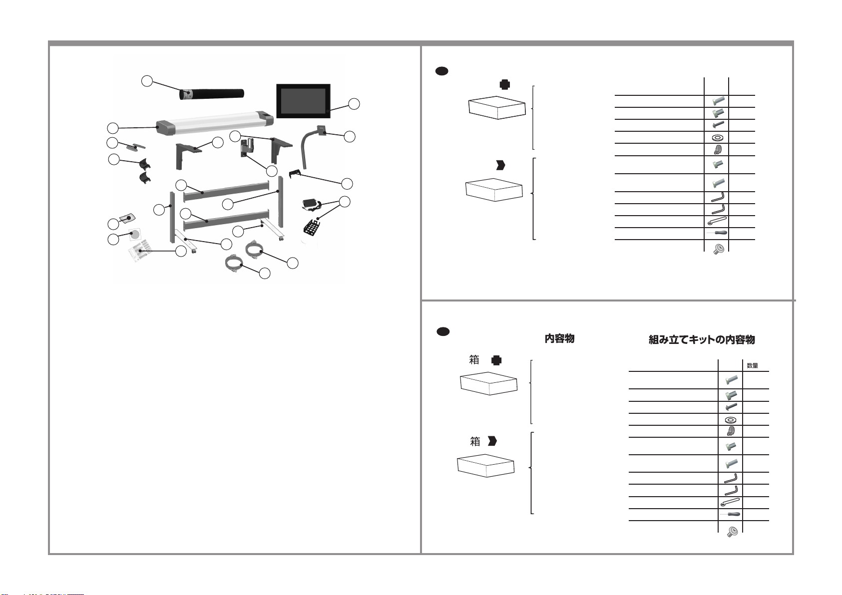
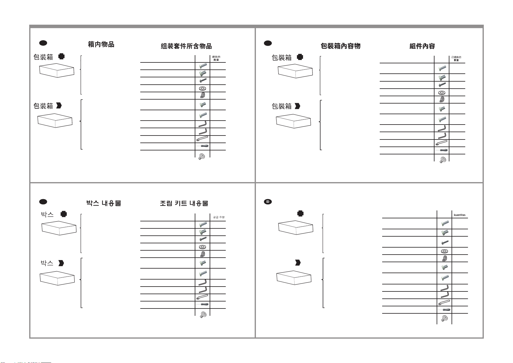
Box contents
1.
Maintenance sheet
2.
Scanner
3.
Paper guides
4.
Return guides
5.
Microber cloth
6.
Documentation CD/DVD
20.
Ethernet cable (3 m)
21.
Ethernet cable (5 m)
22.
Assembly instructions
and other documents
Cross bar
7.
Cross bar
8.
Left leg
9.
Right leg
10.
Left foot
11.
Right foot
12.
Left support
13.
Right support
14.
Arm bracket
15.
Panel PC touch screen
16.
Panel PC arm
17.
Arm support bracket x 2
18.
DC power adapter + Power
19.
adapter tray
Description Quantity
Screw M5 x 16 (Torx T25) for stand feet 8
Screw M5 x 8 (Torx T25) for stand 18
Special screw for scanner (Torx T20) 4
Plastic washer 2
Cable routing clips 10
Screw M4 x 5 for power adapter tray
(Torx T20)
Screw M4 x 10 for panel PC mount
(Torx T20)
Torx T20 key 1
Torx T25 key 1
Spanner for joint 1
Screwdriver T25 1
Flange pan head for arm support 2
Assembly kit contents
supplied
1
4
20
21
JA
保守シート
1.
スキャナ
2.
用紙ガイド
3.
リターン ガイド
4.
マイクロファイバー クロス
5.
マニュアルCD/DVD
6.
イーサネット ケーブル (3m)
20.
イーサネット ケーブル (5m)
21.
組み立て手順およびその他の
22.
マニュアル
クロス バー
7.
クロス バー
8.
左脚部
9.
右脚部
10.
左足部
11.
右足部
12.
左サポート
13.
右サポート
14.
アーム ブラケット
15.
パネルPC画面
16.
パネルPCアーム
17.
アームサポートブラケット x 2
18.
DC アダプタ + 電源アダプタ ト
19.
レイ
説明
スタンド脚部用ネジM5×16 (トル
クスT25)
スタンド用ネジM5×8 (トルクスT25)
スキャナ用専用ネジ (トルクスT20)
プラスチック ワッシャ
ケーブル ルーティング クリップ
電源アダプタ トレイ用ネジM4x5 (
トルクスT20)
パネルPC取り付け用ネジM4x10 (ト
ルクスT20)
トルクスT20用レンチ
トルクスT25用レンチ
ジョイント用スパナ
ドライバT25
アーム サポートのフランジなべ頭
8
18
4
2
10
1
4
1
1
1
1
2
Page 3
ZHCN
维护表
1.
扫描仪
2.
导纸板
3.
强制回位导向块
4.
超细纤维
5.
文档 CD/DVD
6.
以太网电缆(3 米)
20.
以太网电缆(5 米)
21.
组装说明和其他文档
22.
7.
横梁
8.
横梁
9.
左侧支腿
10.
右侧支腿
11.
左侧支脚
12.
右侧支脚
13.
左支座
14.
右支座
15.
弯曲臂支架
16.
平板电脑触摸屏
17.
平板电脑弯曲臂
18.
撑臂臂支架 x 2
19.
直流电源适配器 +
电源适配器托盘
説明
用于支脚的 M5 × 16 (Torx T25) 螺钉
用于支架的 M5 × 8 (Torx T25) 螺钉
用于扫描仪的特殊螺钉 (Torx T20)
塑料垫圈
布线夹
用于电源适配器托盘的 M4 x 5 (Torx
T20) 螺钉
用于平板 PC 底座的 M4 x 10 (Torx
T20) 螺钉
Torx T20 扳手
Torx T25 扳手
接合扳手
螺丝刀 T25
用于臂支架的法兰盘头
ZHTW
維護頁
1.
掃描器
2.
8
18
4
2
10
1
4
1
1
1
1
2
紙張導板
3.
復位導板
4.
微纖維布
5.
說明文件 CD/DVD
6.
乙太網路纜線(3 公尺)
20.
乙太網路纜線(5 公尺)
21.
組裝說明和其他文件
22.
連結層板
7.
連結層板
8.
左腳架
9.
右腳架
10.
左支腳
11.
右支腳
12.
左支座
13.
右支座
14.
懸臂固定座
15.
面板電腦觸控螢幕
16.
面板電腦懸臂
17.
支撐臂托架 x 2
18.
DC 電源變壓器 +
19.
電源變壓器匣
說明
用於底座腳座的 M5 × 16 (Torx
T25) 螺絲
用於底座的 M5 × 8 (Torx T25) 螺絲
用於掃描器的特殊螺絲 (Torx T20)
塑膠墊圈
纜線佈線夾
用於電源整流器托架的 M4 x 5 (Torx
T20) 螺絲
用於面板電腦座的 M4 x 10 (Torx
T20) 螺絲
Torx T20 扳手
Torx T25 扳手
接合扳手
T25 螺絲起子
支撐臂的凸緣平頭
8
18
4
2
10
1
4
1
1
1
1
2
KO
유지보수 용지
1.
스캐너
2.
용지 조정대
3.
리턴 조정대
4.
마이크로파이버 천
5.
설명서 CD/DVD
6.
이더넷 케이블(3m)
20.
이더넷 케이블(5m)
21.
어셈블리 설명서 및 기타 문서
22.
7.
가로대
8.
가로대
9.
왼쪽 다리
10.
오른쪽 다리
11.
왼쪽 발
12.
오른쪽 발
13.
왼쪽 지지대
14.
오른쪽 지지대
15.
암 브래킷
16.
패널 PC 터치 스크린
17.
패널 PC 암
18.
팔지지 브래킷 x 2
19.
DC 전원 어댑터 + 전원 어댑터
트레이
설명
스탠드 발용 나사 M5 × 16(Torx T25)
스탠드용 나사 M5 × 8(Torx T25)
스캐너용 특수 나사(Torx T20)
플라스틱 와셔
케이블 배선 클립
전원 어댑터 트레이용 나사 M4 x
5(Torx T20)
패널 PC 장착용 나사 M4 x 10(Torx
T20)
Torx T20 키
Torx T25 키
조인트용 스패너
드라이버 T25
지지대용 플랜지 팬 헤드
8
18
4
2
10
1
4
1
1
1
1
2
Kotak
Kotak
Isi kotak
1.
Lembar Pemeliharaan
2.
Pemindai
3.
Pemandu kertas
4.
Pemandu pengembalian
5.
Kain microber
6.
CD/DVD dokumentasi
20.
Kabel ethernet (3 m)
21.
Kabel ethernet (5 m)
22.
Petunjuk pemasangan dan dokumen lainnya
Palang silang
7.
Palang silang
8.
Kaki kiri
9.
Kaki kanan
10.
Dasar kaki kiri
11.
Dasar kaki kanan
12.
Penyangga bagian kiri
13.
Penyangga bagian kanan
14.
Braket lengan
15.
Layar sentuh PC panel
16.
Lengan PC panel
17.
Penyangga lengan braket x 2
18.
Adaptor daya DC + Baki
19.
adaptor daya
Isi kit ratikan
Keterangan
Sekrup M5 × 16 (Torx T25) untuk pijakan
dudukan
Sekrup M5 × 8 (Torx T25) untuk dudukan 18
Sekrup khusus untuk pemindai (Torx
T20)
Cincin plastik 2
Klip perutean kabel 10
Sekrup M4 x 5 untuk baki adaptor daya
(Torx T20)
Sekrup M4 x 10 untuk pemasangan PC
panel (Torx T20)
Kunci Torx T20 1
Kunci Torx T25 1
Kunci untuk sambungan 1
Obeng T25 1
Flensa kepala lengkung untuk penopang
lengan
8
4
1
4
2
Page 4
1 2 3 4
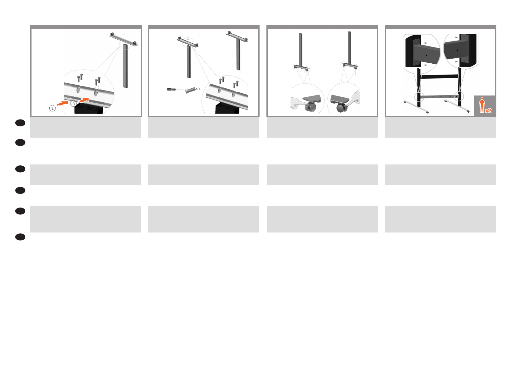
Fix the foot to the leg with 4 screws
EN
JA
4本のネジを使用して脚部に足部を固定します。
ZHCN
确保锁定滚轮。
ZHTW
確認滾輪已鎖定。
KO
바퀴가 잠겨있는지 확인합니다.
ID
Pastikan roda telah terkunci.
Fix the other foot to the other leg with 4 screws.
4本のネジを使用して他の脚部に他の足部を固定しま
す。
使用 4 个螺钉将横梁固定到支腿上。
使用 4 顆螺絲將連結層板固接至腳架。
나사 4개를 사용하여 가로대를 다리에 부착합니다.
Pasang palang silang ke kaki menggunakan empat sekrup.
Make sure the wheels are locked.
ホイールがロックされていることを確認します。
将支座插入到支腿中,并使用 4 个螺钉进行固定。
將支座插在腳架上,並以 4 顆螺絲固定。
지지대를 다리에 넣고 나사 4개로 고정합니다.
Pasang penyangga ke dalam kaki, lalu kencangkan
menggunakan empat sekrup.
Attach the bottom cross bar to the legs using 4 screws.
Make sure the holes for the cable clips are located at the back
when the crossbar is mounted.
4本のネジを使用して脚部にボトム クロス バーを取り
付けます。
クロスバーを取り付ける場合は、背面にケーブル クリ
ップ用の穴があることを確認します。
将纸筐支杆(4 个)插入到插槽中,直到在左右支脚前面
和后面卡入到位。
确保在安装横杆后电缆夹的孔位于背面。
將承接籃支桿 (4) 插入插槽中,直到卡入左、右支腳正面
及背面的定位為止。
確定裝上橫桿後,纜線夾的孔都位於背面。
바스켓 받침대(4개)를 오른쪽과 왼쪽 발의 앞면과 뒷면에
딱 소리를 내면서 고정될 때까지 슬롯에 넣습니다.
크로스바가 설치된 경우 케이블 클립 구멍이 뒤쪽에
있는지 확인합니다.
Pasang palang silang bawah ke kaki menggunakan empat
sekrup.
Pastikan lubang tempat klip kabel telah berada di bagian
belakang saat palang silang dipasang.
Page 5
5
Attach the top cross bar to the legs using 4 screws.
EN
Make sure the holes for the cable clips are located at the back
when the crossbar is mounted.
6
Slot the supports into the legs, and x at the desired height
with 2 screws in each leg.
7
M5×8 x 2
At this point you must decide on which side you are going to t the touch screen assembly. This can be tted on the left or right
side of the stand. The next steps, explain how to t the touch screen assembly when the touch screen is located on the right side of
the stand. To t the touch screen assembly to the left side of the stand, using the same parts, just ‘mirror’ the assembly procedure.
Attach the support bracket to the stand using two M5 x 8 screws. The Torx 25 L-key should be used for the upper screw.
4本のネジを使用して脚部にトップ クロス バーを取り
JA
付けます。
クロスバーを取り付ける場合は、背面にケーブル クリ
ップ用の穴があることを確認します。
ZHCN
使用 4 个螺钉将顶部横梁固定到支腿上。
确保在安装横杆后电缆夹的孔位于背面。
使用 4 顆螺絲將上橫桿固接至腳架。
ZHTW
確定裝上橫桿後,纜線夾的孔都位於背面。
나사 4개를 사용하여 위 가로대를 다리에 부착합니다.
KO
크로스바가 설치된 경우 케이블 클립 구멍이 뒤쪽에
있는지 확인합니다.
ID
Pasang palang silang atas ke kaki menggunakan empat
sekrup.
Pastikan lubang tempat klip kabel telah berada di bagian
belakang saat palang silang dipasang.
サポートを脚部に差し込み、各脚部で2本のネジを目的
の高さに取り付けます。
将支架插入支腿中,并将其固定在所需的高度(每个支腿
上使用 2 个螺钉)。
將支架套入腳架,然後使用 2 顆螺絲將其固定在每個腳
架上所要的高度。
다리에 지지대를 끼우고 각 다리에 나사 2개를 사용하여
원하는 높이로 맞춥니다.
Sisipkan penyangga ke dalam kaki, lalu pasang pada
ketinggian yang diinginkan dengan dua sekrup di setiap
kaki.
この時点で、タッチ画面をどちら側に設置するかを決める必要があります。 画面は、スタンドの左右どちら側にも設
置できます。 これ以降の手順では、タッチ画面をスタンドの右側に固定する場合のタッチ画面の取り付け方法につい
て説明します。 タッチ画面をスタンドの左側に取り付ける場合は、「右側」という説明を「左側」に置き換えてくだ
さい。
2本のM5x8ネジでサポート ブラケットをスタンドに取り付けます。上部のネジにはトルクス25 L型レンチを使用する
必要があります。
此时,您必须确定要将触摸屏组件安装在哪一侧。 可以将其安装在机架左侧或右侧。 接下来的步骤说明了在触摸屏位于
支架右侧时,如何安装触摸屏组件。 将触摸屏组件固定到支架左侧所用的部件相同,只需“镜像”组装步骤即可。
使用两个 M5 x 8 螺钉将支撑架连接到支架上。在拧紧上面的螺钉时需使用 Torx 25 L 扳手。
此時,您必須決定要將觸控螢幕組件安裝在哪一側。 這可安裝在機架的左側或右側。 以下步驟將解釋觸控螢幕放在支
架右側時,觸控螢幕組件的安裝方式。 要將觸控螢幕組件安裝在支架的左側,只需使用相同的零件「對照」組裝程序即
可。
使用兩顆 M5 x 8 螺絲將支架托架裝到底座上。鎖緊上方的螺絲時應使用 Torx 25 L 扳手。
이 지점에서, 어느 쪽에 터치 스크린 어셈블리를 맞출 것이지 결정해야 합니다. 스탠드의 왼쪽 또는 오른쪽에 맞출
수 있습니다. 다음 절차는 터치 스크린을 스탠드 오른쪽에 설치한 경우에 터치 스크린 조립체를 설치하는 방법을
설명합니다. 터치 스크린을 스탠드 왼쪽에 설치하는 경우에는 조립 과정에서 방향만 왼쪽으로 하면 됩니다.
M5 x 8 나사 2개를 사용하여 지지대 브래킷을 스탠드에 부착합니다. 상단 나사에는 Torx 25 L-키를 사용해야 합니다.
Pada tahap ini, Anda harus menentukan sisi pemasangan unit layar sentuh, yakni sisi kiri atau kanan dudukan. Langkah berikutnya
menjelaskan cara memasang unit layar sentuh bila layar sentuh berada di sisi kanan dudukan. Untuk memasang unit layar sentuh
pada sisi kiri dudukan, lakukan prosedur pemasangan dengan cara ‘sebaliknya’ menggunakan komponen yang sama.
Pasang braket penyangga ke dudukan menggunakan dua sekrup M5 x 8. Kunci L Torx 25 harus digunakan untuk sekrup atas.
Page 6

8
x 2
9
10
EN
JA
ZHCN
ZHTW
KO
ID
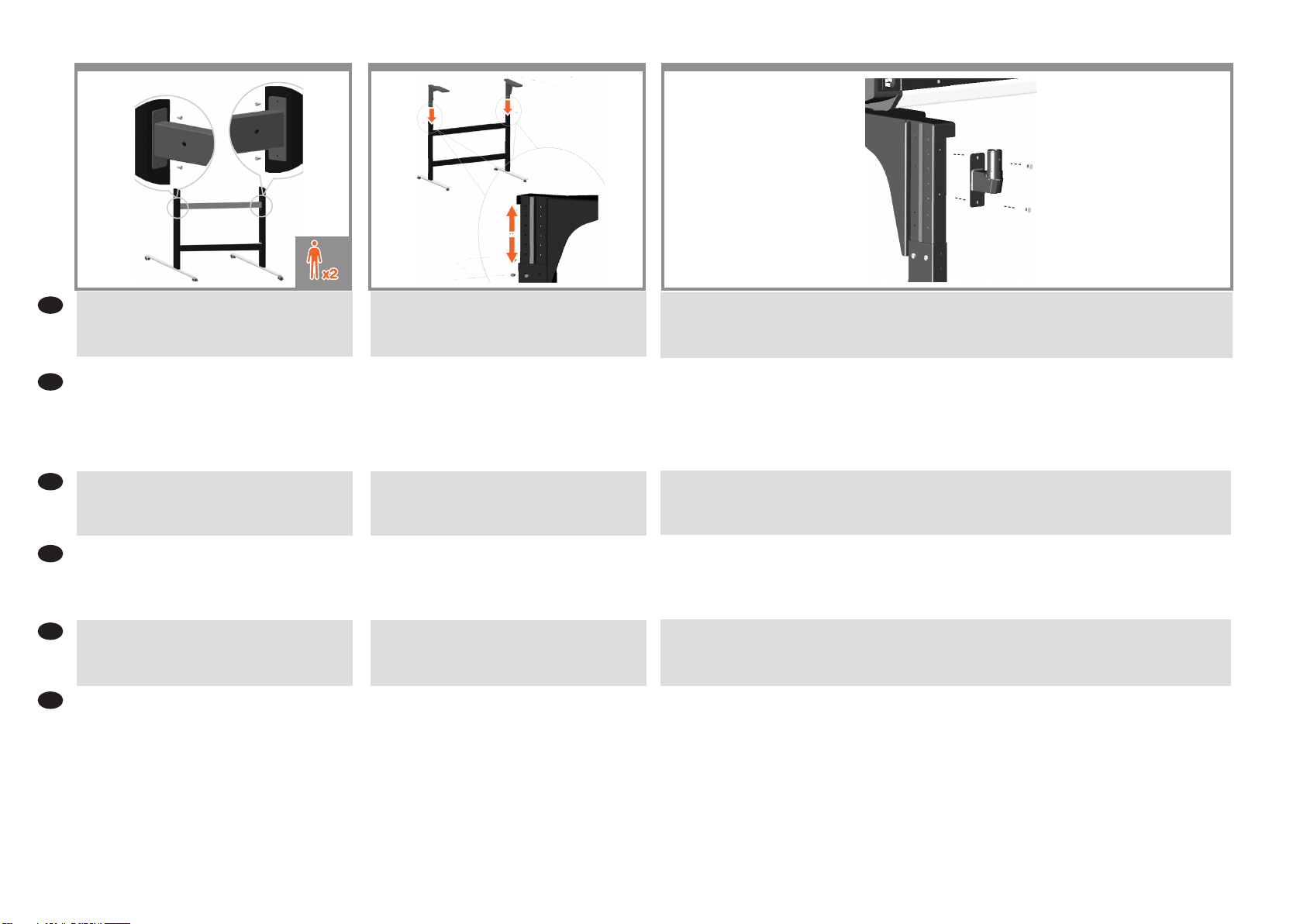
Now you need to decide the height adjustment position. Dierent heights are possible. The arm support bracket (item 18) is
necessary if the second intermediate or highest position is used. In the case of the second intermediate position, use just one arm
support bracket, then x the lower screw of the arm support to the leg and x the upper screw of the arm support to the bracket
as shown in the image. See next step to use the highest adjustment position.
Note: Keep always the arm support bracket as you might need it for future changes in the height.
ここで、高調整位置を決定する必要があります。 さまざまな高位置を使用できます。 アーム サポート ブラケット(ア
イテム18)は、中高位置を使用する場合のみ必要です。 2番目の中位置の場合、アーム サポート ブラケットを1つだけ
使用して、図に示すように、アーム サポートの下側のねじを脚に固定し、アーム サポートの上側のねじをブラケッ
トに固定します。 最高調整位置を使用する場合は、次の手順を参照してください。 注記: 高位置をさらに変更する
ときに必要になる場合があるため、アーム サポート ブラケットはなくさないでください
现在您必须决定最高调整位置。 可能出现不同的高位置。 如果使用第二个中间位置或最高位置,则必须使用臂支撑架
(项目 18)。 在使用第二个中间位置时,只能使用一个臂支撑架,然后将臂支架的下部螺丝固定到支腿上,将臂支架
的上部螺丝固定到托架上(如图所示)。 请参阅下一步以使用最高调整位置。 注意: 请始终保留臂支撑架,因为您可
能需要使用其进一步调整高位
現在要決定高度調整位置。 本產品支援不同的高度位置。 如果使用第二個中間位置或最高位置,則必須使用支撐臂托
架(項目 18)。 如果是第二個中間位置,則只要使用一個支撐臂托架,請將支撐臂的下方螺絲固定至腳架並將支撐臂
的上方螺絲固定至托架,如圖所示。 若要使用最高調整位置,請參閱下一個步驟。 附註: 請務必保留支撐臂托架,因
為日後變更高度位置時可能會需要它
위치를 높이 조정해야 하는 경우가 있습니다. 물론 다른 높이도 가능합니다. 지지대 브래킷(항목 18)은 두 번째 중간
또는 가장 높은 위치를 적용하는 경우에 필요합니다. 두 번째 중간 위치의 경우 지지대 브래킷을 하나만 사용하여,
지지대의 아래 나사를 다리에 고정하고 지지대의 상위 나사를 사진에 표시된 대로 브래킷에 고정하십시오. 위치를
가장 높이 조정하려면 다음 단계를 참조하십시오. 참고: 이후에 높은 위치로 변경할 때 필요할 수도 있기 때문에 지지대
브래킷을 항상 보유하십시오.
Sekarang Anda perlu menentukan posisi penyesuaian tinggi. Posisi tinggi mungkin berbeda. Braket penopang lengan (item 18)
diperlukan jika posisi ketinggian menengah kedua atau tertinggi digunakan. Jika posisi menengah kedua digunakan, gunakan
hanya satu braket penopang lengan, lalu pasang sekrup bawah penopang lengan ke kaki dan pasang sekrup atas penopang
lengan ke braket seperti ditampilkan dalam gambar. Lihat langkah berikutnya untuk menggunakan posisi penyesuaian tertinggi.
Catatan: Simpan selalu braket penopang lengan karena Anda mungkin memerlukannya untuk mengubah posisi ketinggian di lain
waktu.
If you need to adjust the height to adopt the highest stand
position, then you need to use two arm support brackets
(item 18). Use them to x the left and right supports
(items 13 and 14) to the left and right legs (items 9 and 10)
as shown in the image.
最高スタンド位置に従って高位置を調整する必要があ
る場合、アーム サポート ブラケット (アイテム18) が
2つ必要です。それらのアーム サポート ブラケットを
使用して、図に示すように、左右のサポート (アイテ
ム13および14) を左右の脚 (アイテム9および10) に固
定します。
如果您需要根据最高支架位置调整高度,您就需要两个
臂支撑架(项目 18)。使用臂支撑架将左右两侧的支
架(项目 13 和 14)固定到左右两侧的支腿(项目 9 和
10)(如图所示)。
如果您需要根據最高的底座位置來調整高度,則需要兩
個支撐臂托架(項目 18)。使用它們將左側和右側支
撐(項目 13 和 14)固定至左右腳架(項目 9 和 10)
,如圖所示。
가장 높은 스탠드 위치에 따라 높이를 조정하려는
경우 지지대 브래킷(항목 18)이 2개 필요합니다.
사진에 표시된 대로 지지대 브래킷을 사용하여 좌우
지지대(항목 13 및 14)를 좌우 다리(항목 9 및 10)에
고정하십시오
Jika harus menyesuaikan ketinggian menurut posisi
dudukan tertinggi, Anda memerlukan dua braket
penopang lengan, item 18. Gunakan kedua braket tersebut
untuk memasang penopang kiri dan kanan (item 13
dan 14) ke kaki kiri dan kanan (item 9 dan 10) seperti
ditunjukkan dalam gambar.
Lift the scanner into place locating the rubber feet in the
holes indicated.
スキャナを持ち上げ、スキャナをトップ バーの所定の
穴の位置に合わせます。
应将扫描仪抬到适当位置以使橡胶支脚插入所示的孔
中。
將其對準抬放至所指出之圍有橡皮的洞內。
스캐너를 들어올려 위치를 잡아 고무발을 지정된 구멍에
삽입합니다.
Angkat pemindai untuk meletakkannya di dasar kaki
berkaret pada lubang yang ditunjukkan.
Page 7

11
M5×20 x 4
12 14
M4×10 x 4
13
Fix with the four special screws.
EN
Plastic washers should be used when xing the left-hand
side of the scanner to the stand.
JA
スキャナの左側をスタンドに固定する場合は、プラス
チック ワッシャを使用する必要があります。
ZHCN
在将扫描仪的左侧固定到支架上时,应使用塑料垫圈。
將掃描器的左側固定在底座時應使用塑膠墊
ZHTW
圈。
KO
스캐너 왼쪽을 스탠드에 고정할 때 플라스틱 와셔를
사용해야 합니다.
Kencangkan dengan empat sekrup khusus.
ID
Cincin plastik harus digunakan sewaktu memasang sisi kiri
pemindai ke dudukan.
With the protective foam in place, put the panel PC face
down and attach the arm to the rear using four M4×4
screws.
保護用フォームを所定の位置に配置して、パネルPCを
下向きにします。M4×4のネジを4本使用して、アーム
を背面に取り付けます。
保護泡棉裝妥後,讓面板電腦正面朝下,並使用 4 顆
M4×4 螺絲將懸臂固接至背面。
将保护泡沫材料固定到位,将平板电脑面朝下,使用 4
个 M4×4 螺钉将弯曲臂固定到设备后部。
보호용 폼으로 감싼 상태에서 패널 PC 전면을 아래를
향하게 두고 후면에 M4×4 나사 4개를 사용해 암을
부착합니다
Dengan gabus pelindung terpasang pada tempatnya,
letakkan PC panel menghadap ke bawah, kemudian pasang
lengan ke bagian belakang menggunakan empat sekrup
M4x4.
Insert the DC adaptor cable and Ethernet cables into
the bottom, through, and out of the top of the monitor
arm.
DCアダプタ ケーブルとイーサネット ケーブルを
下部に差し込み、モニタ アームの上部から出しま
す。
将直流电源适配器电缆和以太网电缆插入底部、穿过
去,并从监视器臂顶端露出来。
將 DC 整流器纜線和乙太網路纜線插入底部、穿過,然
後從顯示器支臂上方伸出來。
DC 어댑터 케이블과 이더넷 케이블을 모니터 Arm
밑면과 상단을 통과하도록 삽입합니다.
Masukkan kabel adaptor DC dan kabel Ethernet ke bagian
bawah, lalu rutekan hingga keluar ke bagian atas lengan
monitor.
The earth cable comes mounted to the panel PC arm. Use
the Torx 20 L-key to attach the earth cable to the panel PC
using one screw and one star washer.
アース ケーブルをパネルPCアームに取り付けます。
ネジ1本とスター ワッシャ1個を使用し、トルクス20 L
型レンチでアース ケーブルをパネルPCに取り付けま
す。
将接地线安装到平板 PC 支臂上。使用一个螺钉和一
个星型垫圈并使用 Torx 20 L 扳手将接地线连接到平板
PC。
隨附的接地纜線已固定在面板電腦支臂上。使用 Torx 20
L 扳手、一顆螺絲和一個星形墊圈,將接地纜線連接到面
板電腦。
접지 케이블은 패널 PC Arm에 설치됩니다. Torx 20 L키를 사용하여 나사 1개와 스타 모양의 와셔 1개로 접지
케이블을 패널 PC에 부착합니다.
Kabel pengardean terpasang pada lengan PC panel.
Gunakan kunci L Torx 20 untuk memasang kabel
pengardean ke PC panel menggunakan satu sekrup dan satu
cincin sekrup.
Page 8

15
IMAGE TO BE SENT
BY CONTEX
M5×8 x 2
16
17
M4x5 + L-key (Torx 20)
18
EN
Insert the panel PC arm into the support bracket and
secure using two screws.
JA
パネルPCアームをサポート ブラケットに差し込み、2
本のネジで固定します。
ZHCN
将平板电脑弯曲臂插入到支撑架中,并使用两个螺钉进
行固定。
將面板電腦懸臂插入支撐的固定座,並使用兩顆螺絲固
ZHTW
定好。
KO
패널 PC 암을 지지 브래킷에 넣고 나사 2개로
고정합니다.
If you want to lock the tilt position of the panel PC, remove
the cap on the nut and tighten.
パネルPCを傾けた状態で固定する場合は、ナットのキ
ャップを取り外して締めます。
如果要锁定平板电脑的倾斜位置,请取下螺母上的帽盖
并拧紧。
若要鎖定面板電腦的傾斜角度位置,請取下螺帽上的蓋
子並旋緊。
패널 PC의 기울기를 고정하고 싶다면 너트의 뚜껑을
벗기고 조입니다.
Note that the DC adaptor and bracket are mounted
underneath the scanner support, to the side of which the
monitor arm is tted.
DCアダプタとブラケットは、モニタ アームが取り付け
られている側のスキャナ サポートの下に取り付けるこ
とに注意してください。
请注意,直流适配器和托架安装在扫描仪支架下方,与
监视器臂同侧。
請注意,DC 整流器和托架應安裝在掃描器支架下方,與
顯示器支臂同側。
DC 어댑터와 브래킷은 스캐너 지지대 바로 아래, 모니터
Arm이 고정된 쪽에 설치됩니다.
The unit is now assembled and should appear as in the
below illustration.
Important: If this scanner is part of the HP Designjet
SD/HD Pro MFP, your printer should already be assembled,
working and connected to the network in order to connect
the scanner to the printer and to slide it under the scanner.
下の図のようになれば、ユニットの組み立ては完了
です。
重要:このスキャナがHP Designjet SD/HD Pro MFP
の一部である場合、スキャナをプリンタに接続した
り、プリンタをスキャナの下にスライドさせたりする
には、プリンタを組み立てて動作可能な状態にし、ネ
ットワークに接続する必要があります。
现在,设备已组装完毕(如下图所示)。
重要:若此掃描器是 HP Designjet SD/HD Pro MFP 的
一部分,您的印表機應該已經組裝完成、開始運作並連
結至網路,如此一來掃描器才能連結至印表機並滑至掃
描器下。
裝置目前即已組裝完成,且應如下圖所示。
重要说明:如果该扫描仪是 HP Designjet SD/HD Pro
MFP 的一部分,您的打印机应已组装好、正常工作并连
接到网络上,以便将扫描仪连接到打印机上并将打印机
滑到扫描仪下面。
이제 장치가 조립되었으며 아래 그림과 같이 되어야
합니다.
중요: 이 스캐너가 HP Designjet
SD/HD Pro MFP에 포함되어 있으면 프린터를 조립 및
작동하여 네트워크에 연결한 다음, 스캐너를 프린터에
연결하고 스캔하면 됩니다.
ID
Masukkan lengan PC panel ke dalam braket penyangga,
lalu kencangkan menggunakan dua sekrup.
Jika Anda ingin mengunci posisi kemiringan PC panel,
lepaskan kepala mur, lalu kencangkan.
Perlu diketahui bahwa adaptor DC dan braket dipasang di
bawah penyangga pemindai, di sisi tempat lengan monitor
terpasang.
Sekarang unit telah terpasang dan akan terlihat seperti
pada gambar di bawah ini.
Penting: Jika pemindai ini adalah bagian dari HP Designjet
SD/HD Pro MFP, printer harus sudah terpasang, berfungsi,
dan tersambung ke jaringan sebelum pemindai dapat
disambungkan ke printer dan printer dapat disorongkan di
bawah pemindai.
Page 9

19 20
21
22
You are now required to clean the scan area. To do so you
EN
will need the cleaning tools provided in the maintenance
kit and a cleaning uid (not included in the maintenance
kit). Caution: do not use abrasives, acetone, benzene, or
uids that contain these chemicals. Do not spray liquids
directly onto the scanner glass plate or anywhere else in
the scanner.
ここで、スキャン領域のクリーニングを行う必要があ
JA
ります。クリーニングを行うには、保守キットに同梱
されているクリーニング ツールと、液状クリーナが必
要です (クリーナは保守キットには同梱されていませ
ん)。注意: 研磨剤、アセトン、ベンゼン、またはこ
れらの薬品を含んでいる液状クリーナは使用しないで
ください。スキャナのガラス プレートやスキャナの他
の場所に液体を直接吹き付けないでください。
现在,您需要清洁扫描区域。 为此,您需要使用维护工
ZHCN
具箱中提供的清洁工具和清洁剂(不包括在维护工具箱
中)。警告: 不要使用研磨剂、丙酮、苯或包含这些化
学物质的液体。不要将液体直接喷洒到扫描仪玻璃板或
扫描仪中的任何其它地方。
現在需要清理掃瞄區域。 若要進行此作業,您需要具備
ZHTW
維護套件中所提供的清理工具,以及清理液 (維護套件
不附送)。警告: 請勿使用研磨劑、丙酮、苯或含有這
些化學物質的液體。 請勿將液體直接噴灑在掃瞄器的玻
璃板上或是掃瞄器內的任何地方。
이제 스캔 영역을 청소해야 합니다. 스캔영역을
KO
청소하려면 유지보수 키트에 들어 있는 청소 도구와
청소 용액(유지보수키트에 들어 있지 않음)이
필요합니다.주의: 연마재, 아세톤, 벤젠 또는 이들
화학 물질이 포함된 용액을 사용하지 마십시오.
용액을 스캐너 유리판 위나 이외의어떤 부분에도 직접
분사해선 안됩니다.
ID
Kini Anda harus membersihkan area pindai. Untuk
melakukannya, Anda memerlukan alat pembersih yang
tersedia dalam perangkat pemeliharaan dan cairan
pembersih (tidak termasuk dalam perangkat pemeliharaan).
Perhatian: jangan gunakan larutan pembersih keras,
aseton, benzena, atau cairan yang mengandung bahan kimia
tersebut. Jangan semprotkan cairan secara langsung ke pelat
kaca pemindai atau area manapun pada pemindai.
From the front of the scanner, press down the lid while
(1) pushing the two lever buttons on the rear of the lid
towards the center of the scanner until they unlock.
スキャナの正面で、(1) カバーの背面にある2つのレバ
ー ボタンをロックが解除されるまでスキャナの中央に
向かって押しながら、カバーを押し下げます。
从扫描仪正面,按下盖板,同时 (1) 朝扫描仪中心的方
向推动盖板背面的两个手柄按钮,直至其解锁。
從掃描器的正面,按下蓋板,同時 (1) 將蓋板背面的兩
個手柄按鈕往掃描器的中央推動,直到按鈕解除鎖定。
덮개의 뒷면에 있는 두 개의 레버 버튼을 스캐너 중앙
쪽으로 잠금이 해제될 때까지 누르면서(1), 스캐너
앞쪽에서 덮개를 아래로 누릅니다.
Dari bagian depan pemindai, tekan penutup sewaktu (1)
menekan kedua tombol tuas di bagian belakang penutup
ke arah bagian tengah pemindai hingga kunci terbuka.
Lift the lid towards you to open it completely.
カバーを手前に持ち上げて、完全に開きます。
朝自己的方向提起盖板以将其完全打开。
將蓋板往您的方向提起,將它完全打開。
덮개를 몸쪽으로 들어 올려 완전히 엽니다.
Angkat penutup ke arah Anda hingga terbuka sepenuhnya.
Clean the glass with a lint-free cloth and a mild, streak-free,
glass cleaner.
糸くずの出ない布と、刺激が少なく研磨剤が入ってい
ないガラス クリーナを使用して、ガラスをクリーニン
グします。
使用喷有中性无条痕玻璃清洁剂的无绒软布清洁玻璃。
以沒有棉絮的布以及溫和不具亮光的玻璃清理液清理
玻璃。
보풀 없는 천과 순하고 자국이 남지 않는 유리 클리너를
사용하여 유리를 청소합니다.
Bersihkan kaca dengan kain pembersih kaca yang tidak
berserabut dan lembut, serta tidak meninggalkan goresan.
Page 10

23 24
25
26
Dry the glass fully using a separate clean, dry lint-free cloth
EN
like the one provided with the maintenance kit.
保守キットに同梱されているような、別の乾いたき
JA
れいな柔らかい布を使用して、ガラス全体を乾拭き
します。
使用另一块干净的无绒干布(如维护工具箱中提供的软
ZHCN
布)将玻璃完全擦干。
使用另一塊潔淨的無棉絮乾布(類似維護套件所提供的
ZHTW
布料),將玻璃完全擦乾。
깨끗하고 보풀 없는 별도의 마른 천(예:유지보수
KO
키트에 제공된 천)을 사용하여유리의 물기를 충분히
닦아냅니다.
Keringkan kaca menggunakan kain lain yang bersih,
ID
kering, dan tidak berserabut seperti yang tersedia dalam
perangkat pemeliharaan.
Clean the upper precision rollers with a lint-free cloth and a
mild, streak-free, glass cleaner.
糸くずの出ない布と、刺激が少なく研磨剤が入ってい
ないガラス クリーナを使用して、上部の精度ローラー
をクリーニングします。
使用无绒布和柔性无残留玻璃清洗剂擦拭上精密滚筒。
使用無絨布與中性非磨蝕性玻璃清潔劑清潔上方的精
密滾筒。
보풀 없는 천과 순하고 자국이 남지 않는 유리 클리너를
사용하여 상단 정밀 롤러를 청소합니다.
Bersihkan rol presisi atas dengan kain bebas serabut
dan cairan pembersih kaca yang lembut serta tidak
meninggalkan goresan.
Clean the white pressure rollers with a lint-free cloth and a
mild, streak-free, glass cleaner.
糸くずの出ない布と、刺激が少なく研磨剤の入ってい
ないガラス クリーナを使用して、白い加圧ローラーを
クリーニングします。
使用无绒布和柔性无残留玻璃清洗剂擦拭白色压力滚
筒。
使用無絨布與中性非磨蝕性玻璃清潔劑清潔白色壓力
滾筒。
보풀 없는 천과 순하고 자국이 남지 않는 유리 클리너를
사용하여 흰색 압력 롤러를 청소합니다.
Bersihkan rol tekanan putih dengan kain bebas serabut
dan cairan pembersih kaca yang lembut serta tidak
meninggalkan goresan.
Clean the transport rollers and surrounding area.
搬送ローラーと周辺部をクリーニングします。
清洁传输滚筒和周围区域。
清理轉印捲筒以及附近區域。
운반 롤러와 그 주변 영역을 청소합니다.
Bersihkan penggulung pengirim dan area di sekitarnya.
Page 11

27 28
29
30
EN
Dry the white background plate, rollers, and surrounding
area fully using a separate clean, dry lint-free cloth.
JA
糸くずの出ない乾いた布を使用してカバー裏の白いプ
レート、搬送ローラー、および周辺部を拭き、水分を
完全に取り除きます。
ZHCN
使用另一块干净的无绒干布将白色背景板、滚筒和周围
区域完全擦干。
ZHTW
使用另一塊潔淨的無棉絮乾布,將白色的背景壓板、捲
筒以及附近區域完全擦乾。
깨끗하고 보풀 없는 별도의 마른 천을 사용하여
KO
흰색 배경 인자판, 롤러 및 그 주변 영역을 충분히
건조시킵니다.
ID
Keringkan pelat latar putih, penggulung, dan area di
sekitarnya menggunakan kain lain yang bersih, kering, dan
tidak berserabut.
Close the scanner cover and push down on the top to lock
it into place.
スキャナ カバーを閉じ、所定の位置にロックされるま
で上から押します。
合上扫描仪盖板,并向下按顶部以将其锁定到位。
關上掃瞄器蓋子並壓下頂端以鎖入正確位置。
스캐너 덮개를 닫고 완전히 닫힐 때까지위를 누릅니다.
Pasang penutup pemindai, kemudian tekan bagian atasnya
hingga terkunci pada tempatnya.
Insert one end of the y-cable into the DC adapter (under the
scanner support to the left or right) and connect the other
end to the scanner.
Yケーブルの一方をDCアダプタ (右側または左側のス
キャナ サポートの下) に挿入し、もう一方をスキャナ
に接続します。
将 Y 型电缆的一端插入直流适配器(位于扫描仪支架的
左侧或右侧),将另一端连接到扫描仪。
將 Y 型纜線的一端插入 DC 整流器(掃描器支架的下
方,左右兩側都可以),然後將另一端連接到掃描器。
y-케이블의 한 쪽 끝을 DC 어댑터(왼쪽 또는 오른쪽에
있는 스캐너 지지대 아래)에 삽입하고 다른 쪽 끝을
스캐너에 연결합니다.
Masukkan satu ujung kabel y ke adaptor DC (dari bawah
penyangga pemindai ke kiri atau kanan), lalu sambungkan
ujung lain kabel ke pemindai.
Fit the cables into the clips. Then attach the clips to the
stand.
ケーブルをクリップに取り付けます。 クリップをスタ
ンドに取り付けます。
将电源线放入线夹中。 然后将线夹固定到机架上。
將這些電線收納於佈線夾中, 然後將這些夾具固定到
機架。
케이블을 클립에 끼웁니다. 그런 다음 클립을 스탠드에
연결합니다.
Kencangkan kabel ke dalam klip. Setelah itu, pasang
klip ke dudukan.
Page 12

31
IMAGE TO BE SENT
BY CONTEX
x 2
x 1
Insert the network cables into the panel PC and insert the
EN
other end of the 3 m network cable to the ethernet socket
at the left rear of the scanner. Connect the 5 m network
cable to a network socket to connect the panel PC to your
network.
JA
ネットワーク ケーブルをパネルPCに接続し、3mのネ
ットワーク ケーブルのもう一方の端を、スキャナの左
背面にあるEthernetソケットに差し込みます。 5mのネ
ットワーク ケーブルをネットワーク ソケットに接続
し、パネルPCをネットワークに接続します。
ZHCN
将网线插入到平板电脑中,并将 3 米网线的另一端插入
到扫描仪左后方的以太网插槽中。 将 5 米网线连接到网
络插槽中以将平板电脑连接到网络上。
32
Connect the power cord to the y-connector, and into a
power outlet.
電源コードを y コネクタとコンセントに差し込みま
す。
将电源线与 Y 形接头相连,然后插入电源插座。
33
Switch on the scanner power switch at the rear.
背面にあるスキャナの電源スイッチを入れます。
打开扫描仪背面的电源开关。
34
Press the power button below the screen of the panel PC.
パネルPCの画面の下の電源ボタンを押します。
按平板 PC 屏幕下方的电源按钮。
將這些網路線插入至面板電腦,再將 3 公尺網路線的另
ZHTW
一端插入掃描器左後方的乙太網路插座中。 將 5 公尺網
路線連接到網路插座,以連接面板電腦與您的網路。
네트워크 케이블을 패널 PC에 끼우고 네트워크 케이블
KO
(3m)의 다른 끝을 스캐너 왼쪽 후면의 이더넷 소켓에
삽입합니다. 네트워크 케이블(5m)를 네트워크 소켓에
연결하여 패널 PC를 네트워크에 연결합니다.
Masukkan kabel jaringan ke dalam PC panel, lalu
ID
masukkan ujung lain kabel jaringan 3 m ke soket
ethernet di bagian kiri belakang pemindai. Sambungkan
kabel jaringan 5 m ke soket jaringan untuk
menghubungkan PC panel ke jaringan Anda.
將電源線與 Y 型連接器連接,並插入電源插座。
전원 코드를 Y커넥터에 연결한 후 전원 콘센트에
연결하십시오.
Sambungkan kabel daya ke soket y dan stopkontak.
利用背面的掃描器電源開關開啟掃描器。
뒷면의 스캐너 전원 스위치를 전환합니다.
Aktifkan tombol daya pemindai di bagian belakang.
按下面板電腦螢幕下方的電源按鈕。
패널 PC 화면 아래에 있는 전원 버튼을 누릅니다.
Tekan tombol daya di bawah layar PC panel.
Page 13

35
36
37
38
You are now required to calibrate the scanner. For this you
EN
will need the scanner maintenance sheet, found in the
protective tube shown above.
ここで、スキャナのキャリブレーションを行う必要が
あります。 スキャナのキャリブレーションを行うに
JA
は、上の図のような保護チューブに入っている保守シ
ートが必要です。
现在,您需要校准扫描仪。 要进行校准,您需要使用扫
描仪维护页,可从上图所示的保护管中找到。
ZHCN
現在需要校準掃瞄器。 要開始校準,您將需要掃描器維
護頁(位於上圖所示的保護管中)。
ZHTW
이제 스캐너를 보정해야 합니다. 스캐너를 보정하려면
KO
위에 표시된 보호 튜브에 들어 있는 스캐너 유지보수
시트가 필요합니다.
ID
Kini Anda harus mengkalibrasi pemindai. Untuk
melakukannya, Anda memerlukan lembar pemeliharaan
pemindai yang terdapat dalam tube pelindung seperti
ditampilkan di atas.
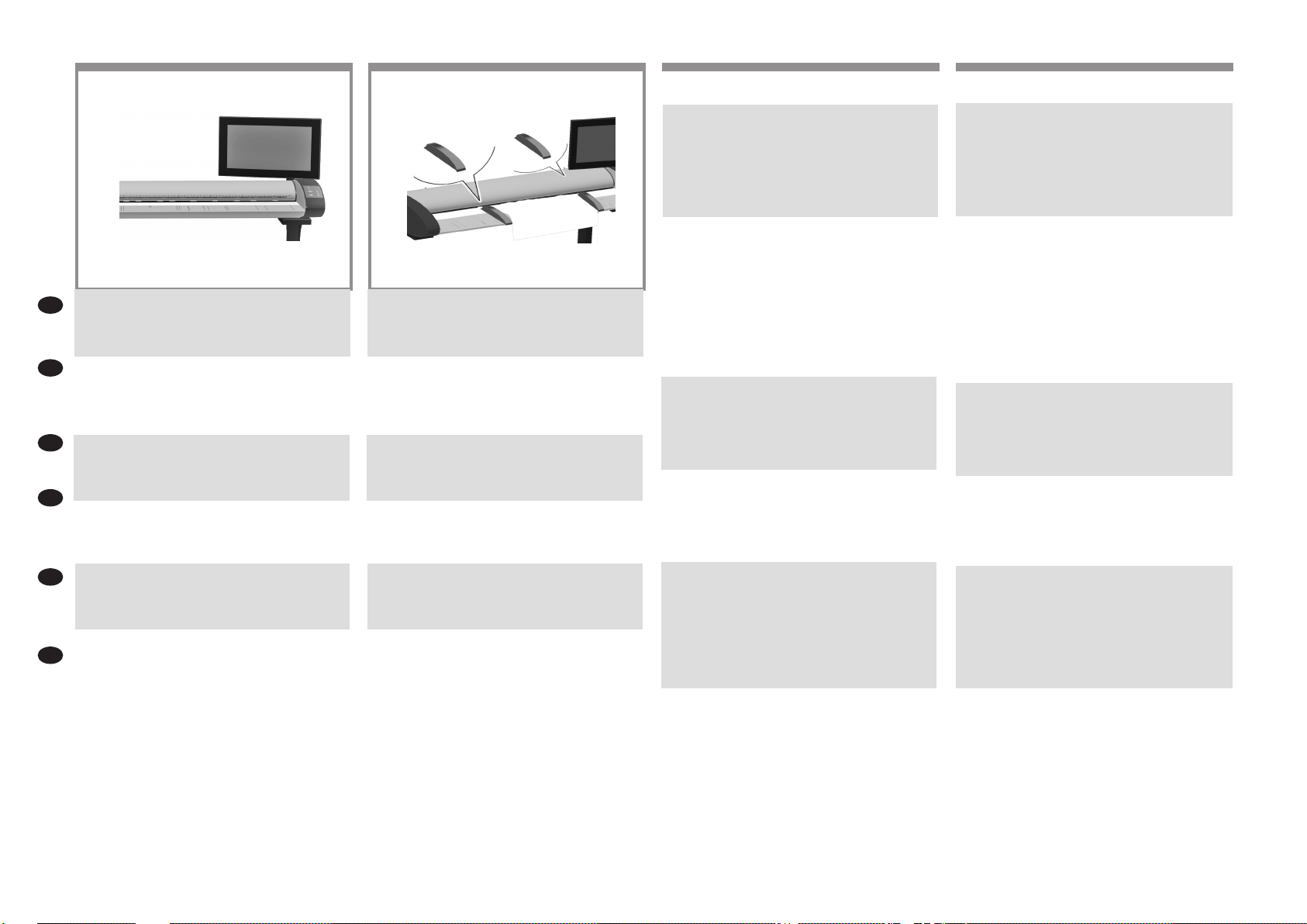
Note: When switching on the panel PC touch screen a ‘Please
make sure the scanner is connected and turned on’ message
may appear. The message will disappear when the scanner
is discovered. Press ‘Cancel’ to enter ‘Demo’ mode.
注記: パネルPC画面の電源を入れると、スキャナが接
続されており、電源が入っていることを確認するメッ
セージが表示されます。 スキャナが検出されると、メ
ッセージは消えます。 [キャンセル] を押すと、デモ モ
ードで起動します。
注: 在打开平板电脑触摸屏时,可能会显示“请确保连接
并打开扫描仪”消息。 在找到扫描仪时,该消息将消失。
按“取消”以进入“演示”模式。
附註: 開啟面板電腦觸控螢幕電源時,可能會出現
「Please make sure the scanner is connected and
turned on」(請確定已連接並開啟掃描器) 訊息。 當系統
找到掃描器後,訊息隨即消失。 按下「取消」進入「示
範」模式。
참고: 패널 PC 터치 스크린을 전환할 때는 ‘스캐너가
연결되어 있고 켜져 있는지 확인하십시오.’라는
메시지가 표시될 수 있습니다. 스캐너가 발견되면
이러한 메시지가 표시됩니다. ‘취소’를 눌러 ‘데모’
모드로 들어갑니다.
Catatan: Saat mengaktifkan layar sentuh PC panel, maka
pesan ‘Pastikan pemindai telah tersambung dan aktif’
akan ditampilkan. Pesan tidak akan ditampilkan lagi bila
pemindai ditemukan. Tekan ‘Batalkan’ untuk masuk ke
mode ‘Demo’.
To start the maintenance procedure:
a) On the touch screen, press the Setup tab.
b) Press the Scan Options button.
c) Press the Calibrate button.
Untuk memulai prosedur perawatan:
a) Pada layar sentuh, tekan ke tab setup.
b) Tekan tombol Scan Options [Opsi Pemindaian].
c) Tekan tombol Kalibrasikan.
The maintenance wizard will ask you to insert the
maintenance sheet. The sheet’s printed side must be face
up. Feed the paper in aligning the two midpoint arrows.
Press ‘Next’ to continue.
保守ウィザードにより、保守シートを挿入するように
求められます。 シートは、印刷面を上向きにして挿
入する必要があります。 2つの中心にある矢印を合わ
せて、シートを挿入します。 [次へ] を押して続行し
ます。
维护向导将要求您插入维护纸张。 必须将纸张的打印
面朝上。 进纸并将两个中间箭头对齐。 按“下一步”继续
操作。
維護精靈會要求您插入維護紙。 該單張紙的列印面必須
朝上。 對齊兩個中點箭號送入紙張。 按下「下一步」
以繼續。
유지보수 마법사에서 유지보수 시트를 삽입하라는
메시지가 표시됩니다. 시트의 인쇄된 면이 위를 향해야
합니다. 두 개의 중간 지점 화살표에 맞춰 용지를
넣습니다. 계속하려면 ‘다음’을 누릅니다.
Panduan pemeliharaan akan meminta Anda memasukkan
lembar pemeliharaan. Sisi cetak kertas harus menghadap
ke atas. Masukkan kertas pada posisi sejajar dengan
titik tengah 2 tanda panah. Tekan ‘Berikutnya’ untuk
melanjutkan.
Page 14
39
Now follow the instructions that appear on the touch screen.
EN
When the maintenance procedure has completed, remove
the scanner maintenance sheet and return it to its protective
tube.
タッチ スクリーンに表示される指示に従います。 保守
JA
作業が完了したら、保守シートを取り出して、保護チ
ューブに戻します。
ZHCN
现在,按照触摸屏上显示的说明进行操作。 维护过程完
成后,取下扫描仪维护页,然后将其放回保护管中。
ZHTW
現在請依照觸控螢幕上出現的指示進行。 維護程序完成
後,取出掃描器維護頁,然後將之放回保護管。
이제 터치 스크린에 표시된 지시를따릅니다. 유지보수
KO
과정이 완료되면 스캐너 유지보수 용지를 제거하고 보호
용 튜브에 다시 넣습니다.
Kini ikuti petunjuk yang ditampilkan pada layar sentuh.
Bila prosedur pemeliharaan telah selesai, keluarkan
ID
lembar pemeliharaan pemindai, lalu kembalikan ke tube
pelindungnya.
40
Your HP Designjet comes equipped with two
magnetic media guides; these can be placed and moved as
required.
HP Designjet は 2 つの用紙ガイドを装備した状態で出
荷されますが、必要に応じてセットしたり、移動した
りすることができます。
HP Designjet 配有两个磁介质导板;可根据需要放置和
移动这些导板。
您的 HP Designjet 配備兩個磁性媒體導板,可視需要放
置與移動。
HP Designjet에는 두 개의 자성 용지 가이드가 부착되어
있으며, 필요에 따라탈부착할 수 있습니다.
HP Designjet dilengkapi 2 pemandu media magnetis yang
dapat dipasang dan dilepas, bila diperlukan.
41
Next, you should check the TCP/IP settings in your touch
screen, and correct them if necessary. If you intend to scan
to the network, with the HP Designjet scan software, les
to be shared across the network should be placed in the D:\
images directory. Once a les is saved to this directory it can
be accessed through the network, from any computer with
any operating system. For more guidance on this issue, see
the user documentation that came with your unit.
次に、タッチ スクリーンで TCP/IP 設定を確認し、必
要であれば設定を修正します。HP Designjet スキャン
ソフトウェアを使用してスキャン結果をネットワーク
上に出力する場合は、ネットワークで共有するファイ
ルを D:\images フォルダ内に置く必要があります。こ
のフォルダにファイルを保存すると、オペレーティン
グ システムに関係なく、任意のコンピュータからそ
のファイルにネットワーク経由でアクセスすることが
できます。
この手順についての詳細は、ユニットに同梱のユーザ
マニュアルを参照してください。
接下来,您应该在触摸屏上检查 TCP/IP设置,并在必要
时更正这些设置。如果要使用 HP Designjet 扫描软件扫
描到网络上,应将在网络上共享的文件放在 D:\images
目录中。将文件保存到此目录中后,可以从使用任何操
作系统的任何计算机中通过网络访问该文件。有关此问
题的指导说明,请参见设备附带的用户文档。
接下來,應檢查觸控螢幕上的 TCP/IP 設定,並視需要
進行更正。若想要利用 HP Designjet 掃瞄軟體掃瞄網
路,則跨網路共用之檔案應置於 D:\images 目錄中。將
檔案儲存至此目錄後,使用者就可以在整個網路上,從
執行任何作業系統的電腦存取該檔案。如需關於此問題
的指南,請參閱裝置所提供的使用者說明文件。
다음으로 터치 스크린의 TCP/IP 설정을 확인하고, 필요
한 경우 설정을 수정해야 합니다. 네트워크에 스캔하려
는 경우에는 HP Designjet 스캔 소프트웨어를 사용하여
네트워크에서 공유할 파일을 D:\images 디렉토리 에 두
어야 합니다. 이 디렉터리에 파일이 저장되면 어느운영
체제를 실행하는 어떤 컴퓨터에서든지 네트워크를 통
해 파일에 액세스할수 있습니다. 이 문제에 대한 자세
한 지침은 장치와 함께 제공된 사용자 설명서를 참조하
십시오.
Selanjutnya, Anda harus memeriksa pengaturan TCP/IP
pada layar sentuh, kemudian perbaiki jika perlu. Jika Anda
ingin memindai ke jaringan menggunakan perangkat lunak
pemindaian HP Designjet, le yang akan digunakan seluruh
jaringan harus disimpan dalam direktori D:\\images. File
yang tersimpan dalam direktori ini dapat diakses melalui
jaringan dari komputer manapun dengan sistem operasi
apapun. Untuk panduan lebih lanjut tentang masalah ini,
lihat dokumen pengguna yang diberikan bersama perangkat Anda.
42
To add an HP Designjet printer to the printer list in your
scanner software, follow these steps:
1: On the touch screen go to the setup tab.
2: Press option button and select system.
3: Press the button for the printer you wish to install.
4: Follow the instructions on the screen.
HP Designjet プリンタをお使いのスキャナソフトウェ
アのプリンタ リストに追加するには、次の手順に従っ
てください。
1: タッチ スクリーン上の [セットアップ] タブを押し
ます。
2: [オプション] ボタンを押してシステムを選択しま
す。
3: インストールするプリンタのボタンを押します。
4: タッチ スクリーンの指示に従います。
要将 HP Designjet 打印机添加到扫描仪软件的打印机列
表中,请按照下列步骤进行操作:
1: 在触摸屏上,转到“设置”标签。
2: 按“选项”按钮,然后选择“系统”。
3: 按要安装的打印机的按钮。
4: 遵照屏幕上的说明进行操作。
若要將 HP Designjet 印表機新增至掃描器軟體中的印表
機清單,請依照下列步驟執行:
1: 請於觸控螢幕上進入「設定」索引標籤。
2: 按下「選項」按鈕並選擇系統。
3: 按下欲安裝之印表機的按鈕。
4: 依照螢幕上的指示執行。
HP Designjet 프린터를 스캐너 소프트웨어의프린터 목
록에 추가하려면 다음 단계를수행하십시오.
1: 터치 스크린에서 설정 탭으로이동합니다.
2: 옵션 버튼을 누르고 시스템을선택합니다.
3: 설치하려는 프린터에 대한 버튼을누릅니다.
4: 화면에 표시된 지시를 따릅니다.
Untuk menambahkan printer HP Designjet ke daftar printer
dalam perangkat lunak pemindai, ikuti langkah-langkah
sebagai berikut:
1: Pada layar sentuh, buka tab setup [kongurasi].
2: Tekan tombol option [pilihan], lalu pilih system [sistem].
3: Tekan tombol untuk printer yang akan diinstal.
4: Ikuti petunjuk pada layar.
Page 15

43
44
EN
For any further information on how to use your scanner, see
the online help system available from your touch screen
using the button above.
スキャナの使用方法についての詳細は、タッチ スクリ
JA
ーンのボタン (下図を参照) を押して、オンライン ヘル
プを参照してください。
有关如何使用扫描仪的任何其它信息,请使用下面的按
ZHCN
钮查看触摸屏中提供的联机帮助系统。
ZHTW
如需任何使用掃瞄器方法的資訊,請使用以下按鈕從觸
控螢幕參閱可用的說明系統。
스캐너 사용 방법에 대한 더 자세한 정보는 터치
KO
스크린에서 아래 버튼을 사용하여 볼 수 있는 온라인
도움말 시스템을참조하십시오.
Untuk informasi lebih lanjut tentang cara menggunakan
ID
pemindai, lihat sistem bantuan online yang tersedia dari
layar sentuh menggunakan tombol di bawah ini.
Keep these instructions
In order to perform routine maintenance (once a month) you will nd it useful to refer again to the following sections:
• Cleaning the scan area
• Alignment and calibration
このガイドは保管しておいてください。
定期保守は 1 ヵ月に 1 回程度行ってください。その際には、以下のセクションを参照すると便利です。
• スキャン領域のクリーニング
• アライメントとキャリブレーション
遵循以下说明
要执行日常维护(每月一次),您会发现再次参考以下部分会非常有帮助:
• 清洁扫描区域
• 对齐和校准
請保留下列說明
若要執行例行性維護 (每月一次),再次參閱下列章節相當有幫助:
• 清理掃瞄區域
• 對齊與校準
다음 지침을 따르십시오.
일상적인 유지보수 작업(한 달에 한 번)을 하려면 다음 섹션을 다시 참조하는것이 좋습니다.
• 스캔 영역 청소
• 유지보수 및 보정
Simpan petunjuk ini
Saat melakukan pemeliharaan rutin (sekali dalam sebulan), sebaiknya lihat kembali bagian di bawah ini:
• membersihkan area pindai
• Penyelarasan dan kalibrasi
Page 16

Legal notices
© Copyright 2015 HP Development Company, L.P.
The information contained herein is subject to change without
notice. The only warranties for HP products and services are set
forth in the express warranty statements accompanying such
products and services. Nothing herein should be construed as
constituting an additional warranty. HP shall not be liable for technical or editorial errors or omissions contained herein.
 Loading...