

Page 1

HP PS1810 Switch
Installation and Getting Started Guide
HP PS1810-8G (J9833A)
HP PS1810-24G (J9834A)
Power over Ethernet PD
Page 2

Page 3

HP PS1810 Switches
Installation and Getting Started Guide
Page 4

© Copyright 2013 Hewlett-Packard Development Company, L.P.
The information contained herein is subject to change without notice.
This document contains proprietary information, which is protected by copyright. No part of this document may be photocopied,
reproduced, or translated into another language without prior written consent of Hewlett-Packard.
Manual Part Number
5998-4329
June 2013
Applicable Products
HP PS1810-8G (J9833A)
HP PS1810-24G (J9834A)
Safety
Before installing and operating this product, please read the “Installation precautions” in Chapter 2, “Installing the switch”, and the safety
statements in General Safety and Regulatory Information booklet included with the product.
Disclaimer
HEWLETT-PACKARD COMPANY MAKES NO WARRANTY OF ANY KIND WITH REGARD TO THIS MATERIAL,
INCLUDING, BUT NOT LIMITED TO, THE IMPLIED WARRANTIES OF MERCHANTABILITY AND FITNESS FOR A
PARTICULAR PURPOSE. Hewlett-Packard shall not be liable for errors contained herein or for incidental or consequential damages in
connection with the furnishing, performance, or use of this material.
The only warranties for HP products and services are set forth in the express warranty statements accompanying such products and
services. Nothing herein should be construed as constituting an additional warranty. HP shall not be liable for technical or editorial errors
or omissions contained herein.
Hewlett-Packard assumes no responsibility for the use or reliability of its software on equipment that is not furnished by Hewlett-Packard.
War ranty
For the latest license and warranty information, see www.hp.com/support/networking-warranties.
For a copy of the warranty terms specific to your HP products, contact an HP authorized dealer or the HP Sales and Service Office in
your country/region.
Page 5

Contents
1 Switch overview
Switch hardware description . . . . . . . . . . . . . . . . . . . . . . . . . . . . . . . . . . . . . . . . 1-2
Network ports . . . . . . . . . . . . . . . . . . . . . . . . . . . . . . . . . . . . . . . . . . . . . . . 1-3
LEDs . . . . . . . . . . . . . . . . . . . . . . . . . . . . . . . . . . . . . . . . . . . . . . . . . . . . . . 1-4
Reset button . . . . . . . . . . . . . . . . . . . . . . . . . . . . . . . . . . . . . . . . . . . . . . . . . 1-5
Clear button . . . . . . . . . . . . . . . . . . . . . . . . . . . . . . . . . . . . . . . . . . . . . . . . . 1-5
Power connector . . . . . . . . . . . . . . . . . . . . . . . . . . . . . . . . . . . . . . . . . . . . . 1-5
Switch features . . . . . . . . . . . . . . . . . . . . . . . . . . . . . . . . . . . . . . . . . . . . . . . . . . 1-6
2 Installing the switch
Included parts . . . . . . . . . . . . . . . . . . . . . . . . . . . . . . . . . . . . . . . . . . . . . . . . . . . 2-1
Installation precautions . . . . . . . . . . . . . . . . . . . . . . . . . . . . . . . . . . . . . . . . 2-3
Installation procedure . . . . . . . . . . . . . . . . . . . . . . . . . . . . . . . . . . . . . . . . . . . . . 2-4
1. Prepare the installation site . . . . . . . . . . . . . . . . . . . . . . . . . . . . . . . . . . . 2-5
2. Mount the switch . . . . . . . . . . . . . . . . . . . . . . . . . . . . . . . . . . . . . . . . . . . 2-5
3. Connect the network cables . . . . . . . . . . . . . . . . . . . . . . . . . . . . . . . . . . 2-14
4. Power on the switch and verify that self-test completes normally . . . . 2-15
SFP installation notes . . . . . . . . . . . . . . . . . . . . . . . . . . . . . . . . . . . . . . . . 2-18
Connections to HP ProLiant Gen8 Servers . . . . . . . . . . . . . . . . . . . . . . . . 2-19
3 Configuring the HP PS1810 Switches
Initial configuration . . . . . . . . . . . . . . . . . . . . . . . . . . . . . . . . . . . . . . . . . . . . . . 3-1
Managing the switch via the 192.168.2.10 address . . . . . . . . . . . . . . . . . . . . . . 3-3
Restoring DHCP addressing to the switch . . . . . . . . . . . . . . . . . . . . . . . . . . . . . 3-4
Next steps . . . . . . . . . . . . . . . . . . . . . . . . . . . . . . . . . . . . . . . . . . . . . . . . . . . . . . 3-5
4 Troubleshooting
Basic troubleshooting tips . . . . . . . . . . . . . . . . . . . . . . . . . . . . . . . . . . . . . . . . . . 4-1
Diagnosing with the LEDs . . . . . . . . . . . . . . . . . . . . . . . . . . . . . . . . . . . . . . . . . 4-2
5
Page 6

Diagnostic tips: . . . . . . . . . . . . . . . . . . . . . . . . . . . . . . . . . . . . . . . . . . . . . . 4-2
Testing the switch by resetting it . . . . . . . . . . . . . . . . . . . . . . . . . . . . . . . . . . . . 4-4
Restoring to factory defaults . . . . . . . . . . . . . . . . . . . . . . . . . . . . . . . . . . . . . . . . 4-4
HP Customer Support Services . . . . . . . . . . . . . . . . . . . . . . . . . . . . . . . . . . . . . . 4-5
Before calling support . . . . . . . . . . . . . . . . . . . . . . . . . . . . . . . . . . . . . . . . . 4-5
A Specifications
Switch Specifications . . . . . . . . . . . . . . . . . . . . . . . . . . . . . . . . . . . . . . . . . . . . A-1
Physical . . . . . . . . . . . . . . . . . . . . . . . . . . . . . . . . . . . . . . . . . . . . . . . . . . . A-1
Electrical . . . . . . . . . . . . . . . . . . . . . . . . . . . . . . . . . . . . . . . . . . . . . . . . . . A-1
Environmental . . . . . . . . . . . . . . . . . . . . . . . . . . . . . . . . . . . . . . . . . . . . . . A-2
Acoustics . . . . . . . . . . . . . . . . . . . . . . . . . . . . . . . . . . . . . . . . . . . . . . . . . . A-2
Safety . . . . . . . . . . . . . . . . . . . . . . . . . . . . . . . . . . . . . . . . . . . . . . . . . . . . . A-2
Standards . . . . . . . . . . . . . . . . . . . . . . . . . . . . . . . . . . . . . . . . . . . . . . . . . . . . . . A-3
Cabling and Technology Information . . . . . . . . . . . . . . . . . . . . . . . . . . . . . . . . A-4
Cabling Specifications . . . . . . . . . . . . . . . . . . . . . . . . . . . . . . . . . . . . . . . . A-4
Technology Distance Specifications . . . . . . . . . . . . . . . . . . . . . . . . . . . . . A-5
Mode Conditioning Patch Cord . . . . . . . . . . . . . . . . . . . . . . . . . . . . . . . . . . . . A-6
Installing the Patch Cord . . . . . . . . . . . . . . . . . . . . . . . . . . . . . . . . . . . . . . A-6
Twisted-Pair Cable/Connector Pin-Outs . . . . . . . . . . . . . . . . . . . . . . . . . . . . . A-8
Straight-through Twisted-Pair Cable for
10 Mb/s or 100 Mb/s Network Connections . . . . . . . . . . . . . . . . . . . . . . A-10
Crossover Twisted-Pair Cable for
10 Mb/s or 100 Mb/s Network Connection . . . . . . . . . . . . . . . . . . . . . . . A-11
Straight-Through Twisted-Pair Cable for
1000 Mb/s Network Connections . . . . . . . . . . . . . . . . . . . . . . . . . . . . . . A-12
B EMC Regulatory Statements
Regulatory Statements . . . . . . . . . . . . . . . . . . . . . . . . . . . . . . . . . . . . . . . . . . . B-1
Index . . . . . . . . . . . . . . . . . . . . . . . . . . . . . . . . . . . . . . . . . . . . . . . . . . . . . .Index-1
6
Page 7

Switch overview
1
The PS1810-8G and PS1810-24G switches are multiport managed gigabit switches
that enable you to build high-performance switched workgroup networks and to work
with HP ProLiant Gen8 Servers. These switches are store-and-forward devices that
offer low latency for high-speed networking.
Throughout this manual, these switches are referred as the PS1810-8G and PS181024G Switches.
■ The PS1810-8G Switch has 8 auto-sensing 10/100/1000BASE-T RJ-45 ports.
Port 1 is a Power over Ethernet Powered Device (PoE PD) port. The switch can
be powered by a network connection to port 1 from PoE power sourcing
equipment (PSE), such as a PoE switch.
■ The PS1810-24G Switch has 24 auto-sensing 10/100/1000BASE-T RJ-45 ports
and two SFP slots (ports 25 and 26) for supported HP SFP fiber-optic
transceivers.
■ The PS1810-8G switch has a unique enclosure that allows physical stacking on
the HP ProLiant MicroServer Gen8 product.
You can connect these switches directly to computers, printers, and servers to provide
dedicated bandwidth to those devices, and you can build a switched network
infrastructure by connecting these switches to hubs, other switches, or routers. The
PS1810 switches have the built-in technology that reports real-time health status for
each Gen8 Server in the network. In addition, these switches offer limited network
management capabilities as well.
1-1
Page 8
Switch overview
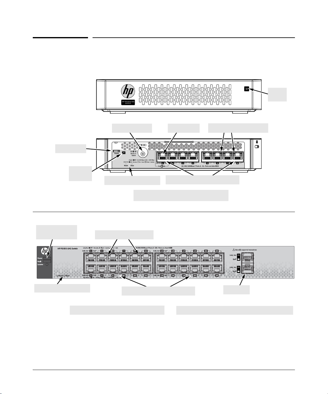
HP PS1810-8G (J9833A)
Link/Act and Speed LEDs
10/100/1000BASE-T RJ-45 ports1
Fault LEDs
Reset and Clear buttons
PoE PD port
1
All RJ-45 ports have the Auto-MDIX feature.
Power
LEDs
Power connector
PD Status
LEDs
1
All RJ-45 ports have the Auto-MDIX feature.
HP PS1810-24G (J9834A)
Link/Act and Speed LEDs
10/100/1000BASE-T RJ-45 ports1
SFP slots
Power, Fault, and
Locator LEDs
Reset and Clear buttons
The back of the PS1810-24G has the AC power connector.
Switch hardware
Switch hardware
1-2
Page 9

Switch overview
Switch hardware
Network ports
■ Auto-sensing 10/100/1000BASE-T ports.
These ports support the “Auto-MDIX” feature, a feature that allows you to use
either straight-through or crossover twisted-pair cables to connect network
devices to the switch.
■ PoE PD port (PS1810-8G Switch only)
A network connection to the PoE PD port from a PoE PSE device can provide
power to the switch.
■ SFP slots for fiber or copper uplinks (PS1810-24G Switch only). SFPs support
the following network connectivity:
Optional Network Connectivity, Speeds, and Technologies
Speed Technology
Cabling
SFP Connector
1
100 Mb/s
1 Gbps
1
To get information about the supported transceivers, see www.hp.com/networking/
support.
1. In the Auto Search textbox, type J4858 (for 100-Mb and Gigabit information).
2. Select one or more products that are displayed in the list. Click Display selected.
100-FX Fiber (multimode) LC
1000-T Copper (twisted-pair) RJ-45
1000-SX Fiber (multimode) LC
1000-LX Fiber (multimode or single mode) LC
3. Click Product support information. The support page opens. In the support page, click
Manuals and find the Transceiver Support Matrix.
For technical details of cabling and technologies, see "Cabling and Technology Information"
in Appendix A.
1-3
Page 10

Switch overview
Switch hardware
LEDs
The front and back panels of the switches provide status LEDs for system monitoring.
The following table lists the functions of the various indicators.
LED State Meaning
Power
(green)
Fault
(orange)
Locator
(blue)
PS1810-24G
Switch only
PD
(green)
PS1810-8G
Switch only
Link/Act
(green)
On The switch is receiving power.
Off The switch is not receiving power.
On On, after the switch is powered on or reset, at the beginning of switch self test. If
the LED remains on, it indicates a detected hardware failure during the self test.
Blinking* Indicates a fault condition on the switch or one of the switch ports. The Link LED
for the port with the fault blinks simultaneously.
Off The normal state; indicates that there are no fault conditions on the switch.
Blinking** The Locator LED helps you locate a specific switch in an area full of switches. The
LED blinks for 30 minutes when activated through the switch software.
Off The Locator LED is disabled by default.
On Power is available on the PoE In port (Port 1).
Blinking* Power is no longer available on the PoE In port. The switch is powered from the
external power adapter. The LED continues to blink until power is restored on the
PoE In port or the switch is reset.
Off Power is not available on the PoE In port.
On The port is enabled and receiving a link indication from the connected device.
Off One of these conditions exist:
• An active network cable is not connected to the port.
• The port is not receiving link beat or sufficient light.
• Green Mode is enabled.
Blinking* Indicates that there is network activity on the port.
Spd
(green)
* The blinking behavior is an on/off cycle once every 1.6 seconds, approximately.
** The blinking behavior is an on/off cycle once every 0.8 seconds, approximately.
On Indicates the port is operating at 1000 Mb/s.
Blinking Indicates the port is operating at 100 Mb/s.
Off Indicates the port is operating at 10 Mb/s.
1-4
Page 11

Switch overview
Switch hardware
Reset button
Use the Reset button to reset the switch while it is powered on. This action clears any
temporary error conditions that might have occurred and runs the switch self test.
Use the Reset button with the Clear button to restore Factory Default settings.
Clear button
Use the Clear button for the following purposes:
■ Deleting Passwords - When pressed, for at least three seconds, the button deletes
any switch web interface access passwords that you may have configured. Use
this feature if you have misplaced the password and need console access.
This button is provided for your convenience. If you are concerned that this
button may be misused, install the switch in a secure location, such as in a locked
wiring closet.
■ Restoring Factory Default Configuration - When the Reset button is pressed
in a specific pattern, any configuration changes you may have made through the
switch console, the web browser interface, and SNMP management are removed,
and the factory default configuration is restored to the switch. For the specific
method to restore the factory default configuration, see “Restoring the Factory
Default Configuration” in chapter 4, “Troubleshooting” of this manual.
Power connector
The PS1810-8G and PS1810-24G switches do not have a power button. They are
powered on when connected to an AC power source.
The PS1810-8G uses an external AC/DC power adapter, either wall mount or inline.
The external AC/DC power adapter supplies 12 volts DC to the switch and automatically adjusts to any AC voltage between 100-240 volts and a frequency of either 50
or 60 Hz. It is not necessary to set a voltage range.
The PS1810-8G Switch can also be powered on by a PoE PD connection to Port 1.
The PS1810-24G Switch has an internal power supply and connects to the AC power
source via a power cable. The switch automatically adjusts to any voltage between
100-127 and 200-240 volts and to a frequency of either 50 or 60 Hz. It is not necessary
to set voltage range.
1-5
Page 12

Switch overview
Switch features
Switch features
The features of the HP PS1810 Switches include:
■ Plug-and-play networking—all ports are enabled, just connect the network
cables to active network devices and your switched network is operational.
■ Auto-MDIX on all twisted-pair ports—all connections can be made using
straight-through twisted-pair cables. Cross-over cable is not required, although
it works.
■ Support for IEEE 802.3az Energy Efficient Ethernet (EEE) features that reduce
power consumption when connected with EEE-compliant devices.
■ Support for automatic discovery and health status reporting of HP ProLiant Gen8
Servers.
■ Automatically negotiated full-duplex operation for all 10/100/1000BASE-T RJ-
45 ports when connected to other auto-negotiating devices.
■ Easy management of the switch through several available interfaces:
• Switch-web interface —an easy-to-use built-in graphical interface that can
be accessed from common Web browsers.
• HP Intelligent Management Center (IMC) — allows network administrators
to discover and map the switches within their network and launch the builtin graphical interface from within IMC to configure the switches.
■ Support for up to 4 trunks for the PS1810-8G and up to 12 trunks for the PS
1810-24G so that you can assign physical links to one logical link (trunk) that
functions as a single, higher-speed link providing dramatically increased
bandwidth. Also known as Link Aggregation.
■ Support for up to 64 IEEE 802.1Q-compliant VLANs so you can divide the
attached end nodes into logical groups that fit your business needs.
■ Support for many advanced features to enhance network performance—for a
description, see the PS1810 Switch Management and Configuration Guide.
■ Support for downloading new switch software for product enhancements and
bug fixes.
1-6
Page 13

Installing the switch
The HP PS1810 Switches are easy to install. They are packed with accessory kits
that allow them to be mounted in a number of different ways. This chapter describes
how to install the PS1810-8G and PS1810-24G switches.
Included parts
The following components are shipped with an HP PS1810 switch:
■ Documentation kit
• Quick Setup Guide and Safety/Regulatory Information
• Software License, Warranty, and Support information
■ Accessory kits:
2
PS1810-24G Switch PS1810-8G Switch
Kit number 5066-0620
• three 3/4” (20-mm M4) screws for wall and
under-table mounting
• three wall anchors
Kit number 5066-2506
• two mounting brackets
• eight 8-mm M4 screws to attach the
mounting brackets to the switch
• four 5/8-inch number 12-24 screws to
attach the switch to a rack
Kit number 5064-4254
• four rubber feet
Kit number 5066-0621
• three 3/4” (20-mm M4) screws for wall
and under-table mounting
• three wall anchors
• cable tie for power cord
Kit number 5066-3084
• four rubber feet
2-1
Page 14

Installing the switch
Included parts
■ PS1810-8G external AC/DC power adapters and power cords:
• Universal Inline AC/DC Power Adapter
All countries/regions 5066-1122*
Power Cords for Inline AC/DC Power Adapter
Australia/New Zealand
Philippines/Thailand
China
India
Indonesia/Israel/Vietnam
Japan
South Africa
South Korea
Taiwan
United Kingdom/Hong Kong/Singapore/Malaysia
Brazil
Argentina
Chile
8121-0870
8121-0664
8120-8373
8121-0702
8120-6314
8120-6316
8120-6314
8120-8441
8121-0963
8120-8699
8121-1081
8120-8367
8121-0514
• Wall Plug-in AC/DC Power Adapters
(AC Power cords are not used)
United States/Canada/Mexico
Continental Europe/Denmark/Norway/Sweden/Switzerland
5184-5863*
5184-5864*
* Complies with Energy Star 5.0 standards.
Japan Power Cord
Warning
■ PS1810-24G Power cords:
Australia/New Zealand
China
Continental Europe
Denmark
Japan
Switzerland
United Kingdom/Hong Kong/Singapore/Malaysia
United States/Canada/Mexico
South Africa
South Korea/Indonesia/Vietnam
India
Israel
Philippines/Thailand
Taiwan
Argentina
Brazil
Chile
8121-0833
8120-8377
8120-6802
8120-6806
8120-6804
8120-6807
8120-8709
8120-6805
8120-6808
8120-6802
8121-0772
8121-1035
8121-0667
8121-0964
8120-6871
8121-1069
8120-6979
2-2
Page 15

Installation precautions
Follow these precautions when installing the switch.
Installing the switch
Included parts
WARNINGS
Cautions
■ When you mount PS1810-8G Switch under HP ProLiant MicroServer
Gen8s, do not stack more than two servers on top of the switch.
■ Before you mount the PS1810-24G Switch in a rack or cabinet, ensure the
rack or cabinet is adequately secured to prevent it from becoming unstable
and falling over.
Devices installed in a rack or cabinet must be mounted as low as possible,
with the heaviest devices at the bottom and progressively lighter devices
installed at the top.
■ When you mount the switch on the wall, ensure that the network ports are
facing up or down to meet national and international safety requirements.
The side vents cannot be placed facing up or down.
■ When installing the switch, ensure that the AC outlet is located near the switch
and is easily accessible in case the switch must be powered off.
■ Ensure that the AC power source circuits are properly grounded.
■ Use only the AC/DC power adapter and power cord (if applicable), supplied
with the switch. Use of other adapters or power cords, including those that came
with other HP Networking products, might result in damage to the equipment.
For those switches that use a power cord, if your installation requires a different
power cord than the one supplied with the switch, be sure to use a power chord
that has the symbol of the safety agency that defines the regulations for power
cords in your country. The mark is your assurance that the power cord can be
used safely with the switch.
■ Ensure the switch does not overload the power circuits, wiring, and over-current
protection. To determine the possibility of overloading the supply circuits, add
together the ampere ratings of all the devices installed on the same circuit as
the switch and compare the total with the rating limit for the circuit. The
maximum ampere ratings are usually indicated on the devices near the AC
power connectors.
■ Do not install the switch in an environment where the operating ambient
temperature might exceed 40C (104 F).
■ Ensure the air flow around the sides of the switch is not restricted.
2-3
Page 16

Installing the switch
Installation procedure
Installation procedure
The following steps summarize switch installation. The rest of this chapter provides
details on these steps.
1. Prepare the installation site (page 2-5). Ensure that the physical environment
into which you will install the switch is properly prepared. The environment
must have the correct network cabling ready to connect to the switch and have
an appropriate location for the switch. See page 2-5 for some installation
precautions.
2. Mount the switch (page 2-5). The PS1810-8G Switch is designed to be stacked
with an HP ProLiant MicroServer Gen8. You can mount the switch on a wall or,
under or on top of a horizontal surface. The PS1810-24G Switch can be mounted
in a 19-inch Telco rack; in an equipment cabinet, on a wall or; under or on top
of a horizontal surface.
3. Connect the network devices (page 2-14). Using the appropriate network
cables, connect the network devices to the switch ports.
4. Optional: Install the SFP transceivers for the PS1810-24G Switch (page 2-
14). The PS1810-24G Switch has two slots for installing SFP transceivers.
Depending on where you install the switch, it might be easier to install the SFPs
first. SFPs can be hot swapped - you can install or remove while the switch is
powered on.
2-4
5. Connect the switch to the AC power source. Once the switch is mounted and
connected to the network devices, plug it into the main power source.
At this point, your switch is fully installed. See the rest of this chapter if you need
detailed information about any of these installation steps.
Page 17
Installing the switch
Installation procedure
1. Prepare the installation site
Follow the installation guidelines to ensure proper operation of the switch in the
network:
■ Verify that all the cables meet the requirements of the “Cabling Specifications”
in Appendix A.
■ Protect the switch from radio frequency interference emissions.
■ Use electrical surge suppression.
■ Use safe connections. The cables, connectors, or shields must not be damaged.
Installation space requirements.
Switch
face
Front
Back At least 1-1/2 inches (3.8 cm) of space for the power cord and switch cooling.
Sides
Clearance requirements
At least 3 inches (7.6 cm) of space for the twisted-pair and fiber-optic cabling.
At least 3 inches (7.6 cm) for cooling, except if the switch is installed in an open
EIA/TIA rack.
2. Mount the switch
HP PS1810-8G Switch
You can stack the HP PS1810-8G Switch with HP ProLiant MicroServers, mount it
on a wall, or on top of or under a horizontal surface.
Before stacking it with HP servers or positioning the switch on a horizontal surface,
attach the rubber feet that are supplied in the accessory kit.
Note If you are mounting the switch on a wall or under a surface, do not attach the rubber
feet.
2-5
Page 18
Installing the switch
Installation procedure
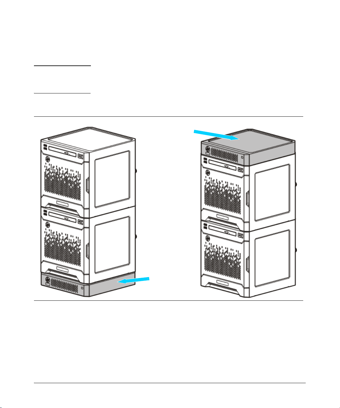
Stack with the HP ProLiant MicroServer Gen8 .
Stack the switch under or on top of the server.
Caution The switch has a limitation on how much weight can be placed on top of it. To reduce
the risk of personal injury or damage to the equipment, stack no more than two servers
on top of the switch.
2-6
Page 19
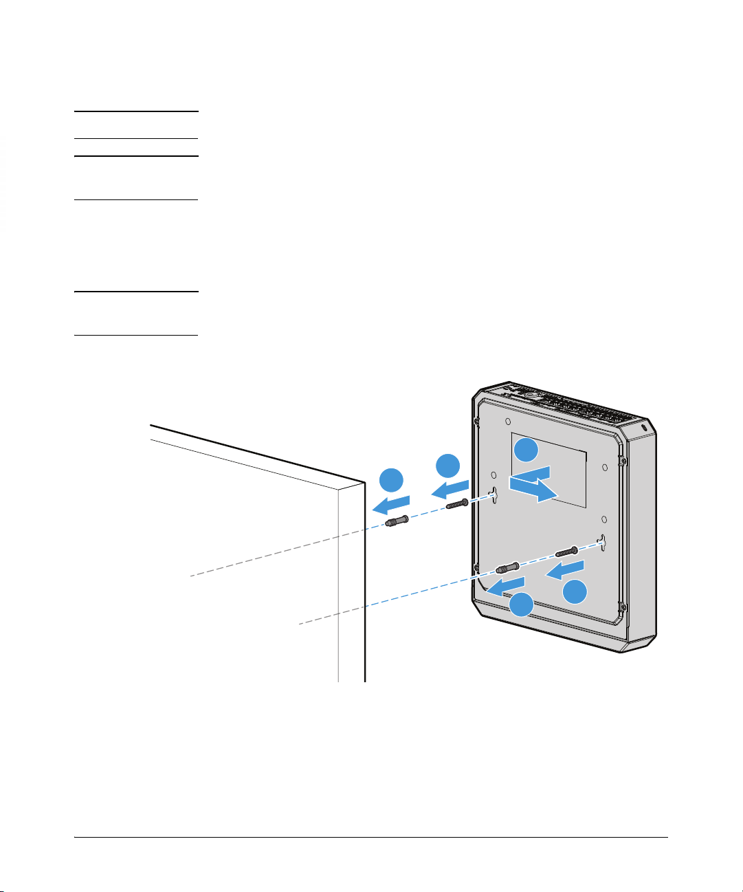
Mounting to a wall.
1
1
2
2
3
Installing the switch
Installation procedure
Important
Wall mount the switch with the network ports facing up or down.
Caution Mount the switch only to a wall or wood surface that is at least 3/4-inch (19 mm)
plywood or its equivalent.
1. Install two 3/4-inch (19 mm) M4 screws (included) into the mounting surface.
The base of the screw head should be distanced approximately 2 mm from the
wall face. Position the screws 6.3 inches (160 mm) apart for the PS1810-8G
Switch. Use the wall anchors if necessary.
Note The mounting holes on the PS1810-8G are not aligned horizontally (as shown in the
illustration). They are offset from each other by 20 mm.
2. Position the switch over the screws, and then slide it down to lock it in place.
2-7
Page 20
Installing the switch
1
1
2
3
Installation procedure
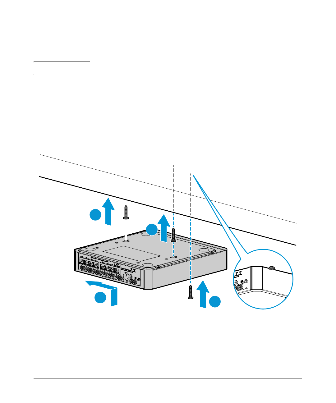
Mounting under a horizontal surface.
You can mount the switch under a horizontal surface.
Caution Mount the switch only to a surface that is at least 1-inch (25.4 mm) thick.
1. Install two 3/4-inch (19 mm) M4 screws (included) into the mounting surface.
The base of the screw head should be distanced approximately 2 mm from the
wall face. Position the screws 6.3 inches (160 mm) apart for the PS1810-8G
Switch. Use the wall anchors if necessary.
2. Position the switch over the screws and slide to lock in place.
3. Optional: Install the third screw at the side of the switch to prevent it from sliding
out of the locked position.
2-8
Page 21

Installing the switch
Installation procedure
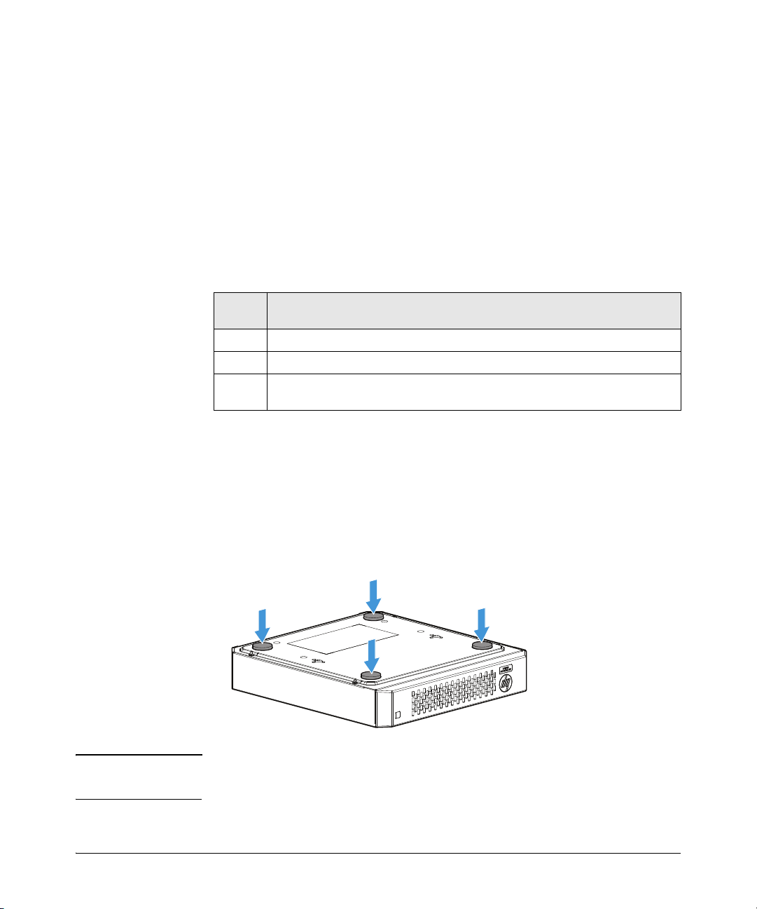
Mounting on top of a horizontal surface.
Place the switch on a table or any other horizontal surface. The switch comes with
rubber feet in the accessory kit. The feet can be used to help keep the switch from
sliding on the surface.
Attach the rubber feet to the four corners on the bottom of the switch within the
embossed angled lines. Use a sturdy surface in an uncluttered area. You might want
to secure the networking cables and switch power cord to the table leg or other part
of the surface structure to help prevent tripping over the cords.
Using a Kensington Security Cable
To prevent unauthorized removal of the switch, you can use a Kensington Slim
MicroSaver security cable (not included) to attach the switch to an immovable object.
2-9
Page 22

Installing the switch
1
1
2
2
Installation procedure
HP PS1810-24G Switch
You can mount the HP PS1810-24G in 19-inch Telco rack or equipment cabinet, on
a wall or on top of a horizontal surface or under a horizontal surface.
Mounting to a Rack or a cabinet .
The PS1810-24G Switches are designed to be mounted in any EIA-standard 19-inch
Telco rack or communication equipment cabinet. The mounting brackets have
multiple mounting holes, and the mounting brackets can be rotated allowing for a
wide variety of mounting options.
Important For safe operation, read the “Installation Precautions” on page 2-3, before
mounting the switch.
Equipment
Cabinet
Note
The screws supplied with the switch are the correct threading for standard EIA/TIA
open 19-inch racks. If you are installing the switch in an equipment cabinet such as
a server cabinet, use the clips and screws that came with the cabinet in place of the
screws that are supplied with the switch.
Complete the following step 1 to attach brackets to the switch. Decide on the four
holes in the cabinet, and then install all the four clips. Then proceed to step 2 to install
the switch in the cabinet.
1. Use a #1 Phillips (cross-head) screwdriver to attach the mounting brackets to the
switch with the included 8-mm M4 screws.
2-10
Page 23

Installing the switch
Installation procedure
Note The mounting brackets have multiple mounting holes and can be rotated allowing
for a wide variety of mounting options. These include mounting the switch so its
front face is flush with the face of the rack as shown in the illustration, or rotating
the brackets so the switch is in a more balanced position with its face forward of the
rack face.
2. Hold the switch with attached brackets in the rack and move it vertically until
rack holes line up with the bracket holes, then insert and tighten the four 12-24
screws holding the brackets to the rack.
2-11
Page 24

Installing the switch
1
2
3
1
2
Installation procedure
Mounting to a wall .
Important
For safe operation, read the “Installation Precautions” on page 2-3, before
mounting the switch.
Wall mount the switch with the network ports facing up or down.
Caution The switch must be mounted only to a wall or to a wood surface that is at least 3/4-
inch (19.1 mm) plywood or its equivalent.
1. Install two 3/4-inch (19 mm) M4 screws, (included) into the mounting surface.
The base of the screw head must be at a distance of approximately 2 mm from
the wall face. Position the screws 10 inches (254 mm) apart for the PS1810-24G
Switch. Use the wall anchors if necessary.
2. Position the switch over the screws, and then slide it down to lock it in place.
2-12
Page 25

Installing the switch
Installation procedure
Mounting under a horizontal surface.
You can use the same screws and a similar technique used to mount the switch on
the wall to mount the switch under a horizontal surface.
Caution The switch must be mounted only to a horizontal surface that is at least
1-inch (25.4 mm) thick.
1. Install two 3/4-inch (19 mm) M4 screws, (included) into the mounting surface.
The base of the screw head must be at a distance of approximately 2 mm from
the wall face. Position the screws 10 inches (254 mm) apart for the PS1810-24G
Switch. Use the wall anchors, if necessary.
2. Position the switch over the mounting screws, and then slide the switch sideways
to lock it in place.
3. Screw a third M4 screw (included) into the table against one side of the switch
to prevent it from sliding out of the locked position.
Mounting on top of a horizontal surface..
Place the switch on a table or other horizontal surface. The switch comes with rubber
feet in the accessory kit. The feet can be used to help keep the switch from sliding
on the surface.
Attach the rubber feet to the four corners on the bottom of the switch within the
embossed angled lines. Use a sturdy surface in an uncluttered area. Secure the
networking cables and switch power cord to the table leg or any other part of the
surface structure to help prevent tripping over the cords.
2-13
Figure 1-1.
Page 26

Installing the switch
Installation procedure
3. Connect the network cables
Connect network devices, such as the HP ProLiant Gen8 Servers, to any of the
PS1810 Switch's RJ-45 network ports using Class 5E or better Ethernet cables. For
more information, see “Connections to HP ProLiant Gen8 Servers” on page 2-19.
You can also connect other devices to the switch, such as printers and PCs, to form
your local network.
Optional for the PS1810-24G Switch: Fiber-optic connections. For the
PS1810-24G Switch, as shown in the illustrations below, you can also install SFPs
and then connect network devices via fiber optic cables. For more information about
using SFPs, see “SFP installation notes” on page 2-18.
For network cable requirements and specifications, see Appendix A, "Specifications"
.
2-14
Page 27

Installing the switch
1
2
1
2
3
Installation procedure
4. Power on the switch and verify that self-test completes
normally
The PS1810 Switches do not have power switches. They are powered on by
connecting them to an AC power source. For safety reasons, the power outlet must
be located near the switch installation.
When the switch is powered on, it performs a diagnostic self test. The self test takes
approximately 45 seconds to complete.
PS1810-8G Switch
1. For the PS1810-8G Switch, connect the AC/DC adapter’s power cord to the
power connector on the back of the switch, and then do one of the following:
• Plug the AC/DC wall power adapter into a nearby properly grounded
electrical outlet
• Connect the power cord to the AC/DC inline power adapter and then into a
nearby properly grounded electrical outlet.
2-15
Page 28

Installing the switch
After Self-Test:
Power LED = On
Fault LED = Off
Installation procedure
The external AC/DC power adapters automatically adjust to any voltage between
100-240 volts and 50 or 60 Hz.
2. Check the LEDs to assure that self test completed successfully:
PS1810-24G Switch
2-16
1. For the PS1810-24G Switch, connect the power cord supplied with the switch
to the power connector on the back of the switch, and then into a properly
grounded electrical outlet.
The switch automatically adjusts to any voltage between 100-127 or 200-240
volts and 50 or 60 Hz. It is not necessary to set a voltage range.
Page 29

Installing the switch
Power, Fault,
Locator LEDs
Port Link/Act and
Speed LEDs
Installation procedure
2. Check the LEDs on the switch as described below.
Self Test LED Behavior:
During the self test:
• Initially, the Power, Fault, Locator, and all port LEDs turn on.
• After several seconds, the Power, Fault and Locator LEDs remain on, and
the port LEDs turn off. Then, each port Link LED is sequentially turned on,
and then turned off.
• The Fault and Locator LEDs turn off when the self test completes.
When the self test completes successfully:
• The Power LED remains on.
• The Fault, and Locator LEDs stay off.
• The port LEDs on the front of the switch go into their normal operational
mode:
– If the ports are connected to active network devices, the Link/Act LEDs
stay on or blink to indicate port activity. The Spd LEDs turn on for 1000
Mb/s links, blink for 100 Mb/s links, or remains off for 10 Mb/s links.
– If the ports are not connected to active network devices, the Link/Act
and Spd LEDs remains off.
If the LED display is different than what is described above, the self test
has not
completed correctly. For diagnostic help, see Chapter 4, "Troubleshooting".
2-17
Page 30

Installing the switch
Installation procedure
SFP installation notes
Caution Use only supported genuine HP SFPs with your switch. Non-HP SFPs are not
supported, and their use might result in product malfunction. If you require additional
HP SFPs, contact your HP Sales and Service Office or authorized dealer. For
information about supported SFPs and mini-GBICs, see “Network ports” on
page 1-3.
Ensure that the network cable is NOT connected when you install or remove an SFP.
WARNING The HP SFPs are Class 1 laser devices. Avoid direct eye exposure to Hot
Swapping SFP transceivers. Supported SFP transceivers that you can install in
your HP switch can be “hot swapped” – removed and installed while the switch
is receiving power. Disconnect the network cables from the SFP transceivers
before hot-swapping them, though.
■ SFP port configuration considerations when changing SFP type. When you
replace an SFP transceiver with another of a different type, the switch might
retain selected port-specific configuration settings that were configured for the
replaced unit. Be sure to validate or reconfigure port settings as required.
■ SFP connections to devices with fixed speed/duplex configurations.
When you connect a device to your switch port that contains an SFP
transceiver, the speed and duplex settings of the switch port and the
connected device must match; otherwise, the device might not link properly.
For some older network devices, including some older HP devices, the
default speed/duplex settings might be predefined (for example, to 1000 Mb/
s/Full Duplex), or otherwise set differently from the default configuration of
your switch port. Because of these default speed/duplex considerations,
make sure that devices connected to your SFP ports are properly configured.
At a minimum, make sure the configurations match.
2-18
■ Environmental limitations. If you are using SFPs with the switch, make
sure that the operating temperature range at the switch installation site does
not exceed the range allowed for the SFP.
Installing the SFPs
Remove the fiber-optic protective cover and retain it for later use. Hold the SFP by
its sides and gently insert it into either of the slots on the switch until the SFP clicks
into place.
Page 31

Installing the switch
Installation procedure
Removing the SFPs
Note You should disconnect the network cable from the SFP before removing it from
the switch.
Depending on when you purchased your HP SFP, it may have either of three different
release mechanisms: a plastic tab on the bottom of the SFP, a plastic collar around
the SFP, or a wire bail.
■ To remove the SFPs that have the plastic tab or plastic collar, push the tab or
collar toward the switch until you see the SFP release from the switch (you can
see it move outward slightly), and then pull it from the slot.
■ To remove the SFPs that have the wire bail, lower the bail until it is approximately
horizontal, and then using the bail, pull the SFP from the slot.
After removing the SFP, replace the fiber-optic protective cover.
Connections to HP ProLiant Gen8 Servers
Connect network devices, such as an HP ProLiant MicroServer Gen8 to any of the
PS1810 Switch’s RJ-45 ports using Class 5E or better Ethernet cables.
Note Any of the switch’s network ports can be used for the following connections. You do
not have to use the specific ports shown in the illustrations.
As shown in the following illustrations, for connection to an HP ProLiant
MicroServer Gen8, it is recommended that you make the following connections:
■ ➊ to ➋ – to provide internet access for the switch and server, connect any of
the switch ports(1 - 8) to your ISP connection, or to a router that is connected to
the internet.
■ ➌ to ➍ – for data communication between the switch and the server, connect
a network cable between any of the available switch ports and either one of the
server’s Ethernet ports. Connection to server ethernet port 2 is shown.
■ ➎ to ➏ – to be able to discover and monitor the health status of HP servers
from the switch, connect a network cable between any of the available switch
ports and the server’s iLO port.
Note It is also possible to use a single cable between the switch and server for data and
iLO communications, but this requires that you connect to server Ethernet port 1, and
requires changes to the server configuration to cause the server Ethernet 1 port to be
“shared” for data and iLO communications. For more information on shared iLO,
see the server documentation.
2-19
Page 32

Installing the switch
1
1
3
2
6
4
5
Installation procedure
PS1810-8G Switch
Connect the PS1810-8G Switch to an HP ProLiant MicroServer Gen8.
HP ProLiant MicroServer Gen8
2-20
Page 33

Installing the switch
1
3
2
4
6
5
1
3
2
4
6
5
Installation procedure
PS1810-24G Switch
Connect the PS1810-24G Switch to an HP ProLiant ML310e Gen8 v2 Server or an
HP ProLiant DL320e Gen8 v2 Server.
HP ProLiant ML310e Gen8 v2 Server
HP ProLiant DL320e Gen8 v2 Server
2-21
Page 34

Installing the switch
Installation procedure
2-22
Page 35

Configuring the HP PS1810 switch
Initial configuration
The HP PS1810 Switches can be managed through a web interface that you can access
from any PC or workstation connected to the switch.
To access the web interface, you must have the switch’s Internet Protocol (IP) address.
In the factory default configuration, the IP address is automatically acquired from a
Dynamic Host Configuration Protocol (DHCP) service that is available on your
network or from your Internet Service Provider (ISP). Most routers provide this
service. The DHCP service automatically provides a network IP address
configuration to devices that request it, such as the HP PS1810 Switches.
Many features are configurable on the HP PS1810 Switches. HP recommends that
at minimum, you configure a management password for switch security. Follow these
procedures to access the switch’s web interface to perform the switch configuration:
3
1. Place the switch close to the PC that you will use for configuration. It helps if
you can see the front panel of the switch while working from your PC.
2. Connect power to the switch, and then start your PC (if it is not already running)
and wait until the switch and PC have finished their start-up sequences.
3. Connect the PC to any port on the switch using a standard Ethernet LAN cable.
Verify that there is a link between the switch and PC by checking the LEDs for
the network port that you are using (For more information on LEDs, see “LEDs”
on page 1-4).
4. If the switch has access to a DHCP service, it automatically acquires an IP
address. Determine the IP address of the switch by examining the client IP
address table on your router (see the router documentation for how to get this
information), or talk to your ISP representative to get the IP address of the switch.
If DHCP service is not available in your network, or for some reason the switch
does not acquire an IP address from the service, the switch defaults to IP address
192.168.2.10 after 120 seconds of automatically attempting to acquire an IP
address.
3-1
Page 36

Configuring the HP PS1810 switch
Initial configuration
Note Alternatively, if you cannot determine the switch’s IP address, you can force it
to use the 192.168.2.10 address by first disconnecting the switch from any router
or internet connection and then unplugging and reconnecting power to it.
To communicate with the switch using the 192.168.2.10 address, see the section
“Managing the switch via the 192.168.2.10 address” on page 3-3” before
continuing these steps.
5. From the PC connected to the switch, open a web-browser session and enter the
switch’s IP address as the URL. This opens the login screen for the switch’s webbrowser interface from which you perform the next steps.
6. Click Login to start a switch web-browser interface session. By default, there is
no password.
A screen similar to the following appears:
3-2
Figure 1-2. HP PS1810 Switch web interface home page
7. To configure a password on the switch web interface, click Maintenance >
Password Manager and New Password. Reenter the new password in the
Confirm New Password field. Passwords can be up to 64 alpha-numeric and
special characters in length, and are case sensitive.
Page 37

Managing the switch via the 192.168.2.10 address
8. Click Apply on the browser configuration screen to save your settings to retain
them when the switch is rebooted.
See the switch’s Management and Configuration Guide for more switch
configuration information.
Configuring the HP PS1810 switch
Note If you cannot remember the switch’s IP address or password, you can restore the
factory default settings by following the procedure described in the
“Troubleshooting” section of this manual.
Managing the switch via the 192.168.2.10
address
If the switch does not acquire an IP address via the DHCP request, it defaults to the
following configuration:
Parameter Factory Default Setting
Password <blank>
IP address 192.168.2.10
Subnet mask 255.255.255.0
Default gateway not set
3-3
To communicate with the switch via the 192.168.2.10 address:
1. Connect a PC directly to any of the switch’s network ports using a standard
Ethernet cable,.
2. Configure the PC’s IP Address and Subnet Mask to allow it to communicate with
the switch through your PC’s Web browser.
For example, for Windows 7, follow these steps:
a. Click Start, and then click Control Panel. In the Control Panel, click
Network and Internet and then Network and Sharing Center.
b. Click Local Area Connection , and then click Properties. If you are prompted
for an administrator password or for a confirmation, type the password or
provide confirmation.
c. Click Internet Protocol Version 4 (TCP/IPv4) and then click Properties.
Note: Record your PC’s current IP settings to be able to restore them later, if
needed.
Page 38

Configuring the HP PS1810 switch
Restoring DHCP addressing to the switch
3. Click Use the following IP address, and then, in the IP address and Subnet mask
fields, type the IP address settings:
a. For IP address, enter an IP address in the same range as the switch’s IP
address, for example, enter 192.168.2.12.
b. For Subnet mask, enter 255.255.255.0, then click OK.
c. Click Close (or OK) to close the Local Area Connection Properties screen.
4. Open the Web browser on the PC, and enter the switch address,
http://192.168.2.10 to access the switch’s web interface.
5. Go back to step 6 on the page 3-2 to configure the switch.
Restoring DHCP addressing to the switch
If you subsequently decide to use automatic IP addressing via a DHCP service in
your network, reconfigure the switch using the following procedures:
1. In the switch’s web interface, click on Network Setup > Get Connected.
2. In the Get Connected page, select DHCP and then click on Apply. See Figure 1-
3 on page 3-5.
3-4
Note: When you make this selection, you will lose connection with the switch.
3. Reboot the switch.
Note: If the DHCP server is ready after the reboot, the switch automatically
obtains an IP address.
4. Now you can use the automatic IP addresses acquired by the switch and your
PC to communicate as described starting with step 4 on page 3-1.
Page 39

Configuring the HP PS1810 switch
Figure 1-3. Get Connected page – selecting DHCP for automatic IP address
Next steps
3-5
Next steps
For more information about the Web browser interface and all the features that can
be configured on the HP 1810 Switch Series, see the HP PS1810 Switches
Management and Configuration Guide, which is available on the HP Website,
http://www.hp.com/networking/support.
To access the manuals web page for the PS1810 switches:
1. Auto Search for PS1810 on
2. Select the switch in the listed items, and click Display selected.
3. The Warranty support and product information page appears.
4. Click Product support information (manuals, FAQs, knowledge base) in the list.
5. The Business Support Center page for the switch opens, click “Manuals” to open
the documentation page for the switch.
http://www.hp.com/networking/support page.
Page 40

Troubleshooting
This section describes how to troubleshoot the switch. For more information, see the
chapter “Troubleshooting” in the HP PS1810 Switch Series Management and
Configuration Guide, available on the HP web site,
http://www.hp.com/networking/support.
This chapter describes the following:
■ Basic troubleshooting tips (page 4-1)
■ Diagnosing with the LEDs (page 4-2)
■ Testing the switch by resetting it (page 4-4)
■ Forgotten the IP address or password (page 4-4)
■ HP Customer Support Services (page 4-5)
4
Basic troubleshooting tips
Common problems and their solutions are listed in the following table.
Problem Resolution
Switch fails Power-On Self
Test (POS T)
Link light does not light when
a cable is connected.
Troubleshoot using the LEDs. See “Diagnosing with the
LEDs” on page 4-2
The switch may be enabled in Green Mode, where port
Link LEDs would be off.
Look for loose or obviously faulty connections. If they
appear to be OK, make sure the connections are snug. If
that does not correct the problem, try a different cable.
4-1
Page 41

Troubleshooting
Diagnosing with the LEDs
Diagnosing with the LEDs
When resetting the switch, or during a power-on self test (POST), LED patterns on
the switch may indicate a problem condition.
1. Check in the table below for the LED pattern you see on your switch.
2. Refer to the corresponding diagnostic tips on the next few pages.
LED Pattern Indicating Problems
2
Diagnostic
Tips
➊
➋
➌
➍
➎
Power Fault PD LED
Off with power cord
or power adapter
plugged in
On Prolonged On
On Blinking
On Off
Off Off Off with cable
1
This LED is not important for the diagnosis.
2
The blinking behavior is an on/off cycle once every 1.6 seconds, approximately.
3
Applies only to the HP PS1810-8G Switch.
1
2
connected to
3
Off
11
1
1
3
port 1
Port LED
1
Blinking
Off with cable
connected
1
Diagnostic tips:
Tip Problem Solution
1. Verify that the power cord or power adapter is plugged into an active AC power
source and to the switch. Make sure these connections are snug.
2. Try power cycling the switch by unplugging the power cord or power adapter
from the AC outlet and then plugging it back in.
3. If the Power LED is still not on, verify that the AC power source works by plugging
another device into the outlet, or try plugging the switch into a different outlet,
or try a different power cord (if applicable).
If the power source and power cord are OK and this condition persists, the switch’s
internal power supply or power adapter might have failed. Call your HP authorized
network reseller, or use the electronic support services from HP to get assistance.
4-2
The switch is not
➊
plugged into an active
AC power source, or
the power adapter (if
applicable) of the
switch might have
failed.
Page 42

Tip Problem Solution
Diagnosing with the LEDs
Troubleshooting
➎
A switch hardware
➋
failure has occurred.
All the LEDs will stay
on indefinitely.
The network port for
➌
which the Link LED is
blinking has
experienced a self test
or initialization failure.
The network
➍
connection is not
working properly.
A PoE power sourcing
equipment (PSE)
device is connected to
port 1 on an HP
PS1810-8G Switch, but
PoE power is not being
supplied.
Try power cycling the switch. If the fault indication reoccurs, the switch might have
failed. Call your HP authorized network reseller, or use the electronic support
services from HP to get assistance.
Try power cycling the switch. If the fault indication reoccurs, the switch port might
have failed. To confirm, try a different port that appears to be good. Call your HP
authorized network reseller, or use the electronic support services from HP to get
assistance.
If the port is an SFP, verify that it is one of the SFPs supported by the switch.
Unsupported SFPs are identified with this fault condition. The supported SFPs are
listed in Chapter 1, “Switch Overview” on page 1-3. The SFPs are also tested by the
switch when they are “hot-swapped”— installed or changed while the switch is
powered on.
To verify that the port has failed, try removing and reinstalling the SFP without
powering off the switch. If the port fault indication reoccurs, replace the SFP.
Try the following steps:
• For the indicated port, verify that both ends of the cabling, at the switch and the
connected device, are secure.
• Verify that the connected device and the switch are both powered on and are
operating correctly.
• Verify that the connected devices comply with the appropriate IEEE 802.3 standard, including transmission of the Link signal.
• If these steps do not resolve the problem, try using a different port or a different
network cable.
Try the following steps:
• Make sure that the PSE device is powered on.
• Make sure that the network cable between the PSE and the switch is fully
connected at both ends.
• On the PSE, make sure that the port being used to provide the PoE power has
appropriate PoE capabilities and priority, and that PoE delivery is enabled on that
port.
• If these steps do not resolve the problem, try using a different network cable.
4-3
Page 43

Troubleshooting
Testing the switch by resetting
Testing the switch by resetting
If you believe the switch is not operating correctly, you can reset the switch to test
its circuitry and operating code. To reset the switch, unplug and plug in the power
cord (power cycling).
Power cycling the switch will cause the switch to perform its power-on self test.
You can reset the switch from the web interface. Login to the switch web interface,
and from the home page, select Diagnostics > Reboot Switch.
Restoring to factory defaults
If you forget the switch IP address or password, you can restore the factory default
configuration by pressing the Reset and Clear buttons.
To restore the factory default settings on the switch, perform these steps:
4-4
1. Using a small, thin tool with blunt ends (such as a paper clip), simultaneously
press both the Reset and Clear buttons on the front of the switch.
2. Continue to press the Clear button while releasing the Reset button.
3. Release the Clear button.
The switch will then complete its self test and begin operating with its configuration restored to the factory default settings.
After completing this procedure, there will be no password, the switch will return to
attempting to automatically acquire an IP address via a DCHP service, and all
configuration settings will be set to factory defaults.
You can restore the factory default configuration to the switch from the web interface.
Login to the switch web interface, and from the home page, select Diagnostics >
Factory Defaults.
Page 44

HP Customer Support Services
Troubleshooting
HP Customer Support Services
If you are still having trouble with your switch, Hewlett-Packard offers support 24
hours a day, seven days a week through the use of a number of automated electronic
services.
The HP web site,
http://www.hp.com/networking/support also provides up-to-date
support information.
Additionally, your HP authorized network reseller can provide you with assistance,
both with services they offer and with services offered by HP.
Before calling HP support
Before you call your networking dealer or HP Support, to make the support process
most efficient, you first should have retrieved the following information:
Information Item Information Location
• Product identification, including for the
switch and any installed SFPs.
• Details about the switch’s status including the operating software (OS)
version, a copy of the switch configuration, and the contents of the Support
file.
• Copy of your network topology map,
including network addresses assigned
to the relevant devices.
The front of the switch, and on labels on the
SFPs.
Switch’s web interface.
For more information about using the web
interface, see the Management and
Configuration Guide for your switch.
Your network records.
4-5
Page 45

Troubleshooting
HP Customer Support Services
4-6
Page 46

Specifications
Switch Specifications
Physical
A
Width Depth Height Weight
PS1810-8G (J9833A)
PS1810-24G (J9834A)
23 cm (9.055 in) 24.5 cm (9.64 in) 4.5 cm (1.77 in) 1.25 kg (2.74 lbs)
33.0 cm (13.0 in) 17.7 cm (6.96 in) 4.5 cm (1.77 in) 1.35 kg (3.0 lbs)
Electrical
AC voltage Maximum current Frequency range
PS1810-8G (J9833A)
PS1810-24G (J9834A)
1
Requires a connection to an external power adapter. The adapter automatically
adjusts to any voltage between 100-127 or 200-240 volts and either 50 or 60 Hz.
2
The switch automatically adjusts to any voltage between 100-127 or 200-240 volts
and either 50 or 60 Hz.
3
The switch can also be powered by a PoE PSE connected to Port 1. Port 1 is an
IEEE 802.3af Compatible PD (PoE Powered Device) - Class 3.
1,3
2
100-240 volts 0.5A 50/60 Hz
100-127 volts
200-240 volts
0.4 A / 0.3 A 50/60 Hz
A-1
Page 47

Specifications
Switch Specifications
Environmental
Operating Non-Operating
Temperature 0C to 40C (32F to 104F) -40C to 70C (-40F to 158F)
Relative humidity
(non-condensing)
Maximum altitude 3.0 Km (10,000 ft)* 4.57 Km (15,000 ft)
15% to 90% at 40C (104F) 15% to 90% at 65C (149F)
* The operating maximum altitude should not exceed that of any accessory that is connected
to any PS1810 Switch.
Acoustics
Power: 0 dB (no fans)
Safety
Complies with:
■ HP PS1810-8G
■ Standards: EN60950-1:2006+A11:2009+A1:2010+A12:2011 / IEC60950-
1:2005; Am 1:2009 CSA22.2 No. 60950-1-07 2nd; UL60950-1 2nd
■ HP PS1810-24G
■ Standards: EN60950-1:2006+A11:2009+A1:2010+A12:2011 / IEC60950-
1:2005; Am 1:2009 CSA22.2 No. 60950-1-07 2nd; UL60950-1 2nd
■ Lasers: EN 60825-1:2007 / IEC 60825-1:2007 Class 1; Class 1 Laser Products
/ Laser Klasse 1 (Use only supported HP SFPs)
A-2
Page 48

Standards
Specifications
Standards
Technology Standards and Safety Compliance
Laser safety information
Technology Compatible with these IEEE
10-T
100-TX
1000-T
100-FX
1000-SX
1000-LX
IEEE 802.3 10BASE-T
IEEE 802.3u 100BASE-TX
IEEE 802.3ab 1000BASE-T
IEEE 802.3u 100BASE-FX EN/IEC 60825 Class 1 Laser Product
IEEE 802.3z 1000BASE-SX EN/IEC 60825 Class 1 Laser Product
IEEE 802.3z 1000BASE-LX EN/IEC 60825 Class 1 Laser Product
standards
EN/IEC standard
compliance
SFP
Lasers
Laser Klasse 1
Laser Klasse 1
Laser Klasse 1
A-3
Page 49

Specifications
Cabling and Technology Information
Cabling and Technology Information
Cabling Specifications
Cabling Specifications
10 Mb/s Operation Category 3, 4 or 5, 100-ohm unshielded twisted-pair (UTP) or
Twisted-pair copper
Multimode fiber
Single mode fiber
1
A mode conditioning patch cord may be required for some Gigabit-LX installations.
See “Mode Conditioning Patch Cord” on page A-6 for more information.
100 Mb/s Operation Category 5, 100-ohm UTP or STP cable, complying with IEEE 802.3u
1000 Mb/s Operation Category 5, 100-ohm 4-pair UTP or STP cable, complying with IEEE
shielded twisted-pair (STP) cable, complying with IEEE 802.3
10BASE-T specifications.
100BASE-TX specifications.
802.3ab 1000BASE-T specifications—Category 5e or better is
recommended. See note on 1000BASE-T Cable Requirements
below.
62.5/125 m or 50/125 m (core/cladding) diameter, low metal
content, graded index fiber-optic cables, complying with the
ITU-T G.651 and ISO/IEC 793-2 Type A1b or A1a standards
respectively.
9/125 m (core/cladding) diameter, low metal content fiber-optic
cables, complying with the ITU-T G.652 and
ISO/IEC 793-2 Type B1 standards.
1
A-4
Page 50

Cabling and Technology Information
Specifications
Note on 1000BASE-T Cable Requirements. The Category 5 networking cables
that work for 100BASE-TX connections should also work for 1000BASE-T, as long
as all four-pairs are connected. But, for the most robust connections, you should use
cabling that complies with the Category 5e specifications, as described in Addendum
5 to the TIA-568-A standard (ANSI/TIA/EIA-568-A-5).
Because of the increased speed provided by 1000BASE-T (Gigabit-T), network cable
quality is more important than for either 10BASE-T or 100BASE-TX. Cabling plants
being used to carry 1000BASE-T networking must comply with the IEEE 802.3ab
standards. In particular, the cabling must pass tests for Attenuation, Near-End
Crosstalk (NEXT), and Far-End Crosstalk (FEXT). Additionally, unlike the cables
for 100BASE-TX, the 1000BASE-T cables must pass tests for Equal-Level Far-End
Crosstalk (ELFEXT) and Return Loss.
When testing your cabling, be sure to include the patch cables that connect the switch
and the other end devices to the patch panels on your site. The patch cables are
frequently overlooked when testing cable. The patch cables must also comply with
the cabling standards.
Technology Distance Specifications
Technology Distance Specifications
Technology Supported cable type Multimode fiber
100-FX multimode fiber any up to 2,000 meters
1000-T twisted-pair copper N/A up to 100 meters
1000-SX multimode fiber 160 MHz*km
1000-LX multimode fiber
single mode fiber
modal bandwidth
200 MHz*km
400 MHz*km
500 MHz*km
400 MHz*km
500 MHz*km
N/A
Supported distances
2 - 220 meters
2 - 275 meters
2 - 500 meters
2 - 550 meters
2 - 550 meters
2 - 550 meters
2 - 10,000 meters
A-5
Page 51

Specifications
Mode Conditioning Patch Cord
Mode Conditioning Patch Cord
The following information applies to installations in which multimode fiber-optic
cables are connected to a Gigabit-LX port. Multimode cable has a design
characteristic called “Differential Mode Delay”, which requires the transmission
signals be “conditioned” to compensate for the cable design and thus prevent resulting
transmission errors.
Under certain circumstances, depending on the cable used and the lengths of the cable
runs, an external Mode Conditioning Patch Cord may need to be installed between
the Gigabit-LX transmitting device and the multimode network cable to provide the
transmission conditioning. If you experience a high number of transmission errors
on those ports, usually CRC or FCS errors, you may need to install one of these patch
cords between the fiber-optic port in your switch and your multimode fiber-optic
network cabling, at both ends of the network link.
The patch cord consists of a short length of single mode fiber cable, coupled to
graded-index multimode fiber cable on the transmit side, and only multimode cable
on the receive side. The section of single mode fiber is connected in such a way that
it minimizes the effects of the differential mode delay in the multimode cable.
Note Most of the time, if you are using good quality graded-index multimode fiber cable
that adheres to the standards listed in this appendix, there should not be a need to use
mode conditioning patch cords in your network. This is especially true if the fiber
runs in your network are relatively short.
Installing the Patch Cord
As shown in the illustration below, connect the patch cord to the transceiver with the
section of single mode fiber plugged in to the Tx (transmit) port. Then, connect the
other end of the patch cord to your network cabling patch panel, or directly to the
network multimode fiber.
If you connect the patch cord directly to the network cabling, you may need to install
a female-to-female adapter to allow the cables to be connected together.
A-6
Page 52

Mode Conditioning Patch Cord
Tx
Rx
To ne twor k
multimode
cabling
Mode Conditioning
Patch Cord
The multimode cable in the patch cord
must match the characteristics of your
network cable
Gigabit-LX port
Single mode section plugs into Tx
port on Gigabit-LX Transceiver or
Gigabit-LX mini-GBIC
Specifications
Example: Connecting a Mode Conditioning Patch Cord for Gigabit-LX
Make sure you purchase a patch cord that has appropriate connectors on each end,
and has multimode fibers that match the characteristics of the multimode fiber in
your network. Most important, the core diameter of the multimode patch cord must
match the core diameter of the multimode cable infrastructure (either 50 or 62.5
microns).
A-7
Page 53

Specifications
Twisted-Pair Cable/Connector Pin-Outs
Twisted-Pair Cable/Connector Pin-Outs
The Auto-MDIX Feature: In the default configuration, “Auto”, the fixed 10/100/
1000BASE-T ports on the switches all automatically detect the type of port on the
connected device and operate as either an MDI or MDI-X port, whichever is
appropriate. So for any connection, a straight-through twisted-pair cable can be
used—you no longer have to use crossover cables, although crossover cables can
also be used for any of the connections. (The 10/100/1000-T ports support the IEEE
802.3ab standard, which includes the “Auto-MDIX” feature.)
If you connect a switch twisted-pair port to another switch or hub, which typically
have MDI-X ports, the switch port automatically operates as an MDI port. If you
connect it to an end node, such as a server or PC, which typically have MDI ports,
the switch port operates as an MDI-X port. In all cases, you can use standard straightthrough cables or crossover cables.
If you use a correctly wired crossover cable, though, the switch will still be able to
automatically detect the MDI/MDI-X operation and link correctly to the connected
device.
Note Using Fixed Configurations. If the port configuration is changed to any of the fixed
configurations though, for example 100 Mb/s/full duplex, the port operates as MDIX only and the correct cable type must be used: for connections to MDI ports, such
as end nodes, use a straight-through cable; for connections to MDI-X ports, such as
on hubs and other switches, use a crossover cable.
Other Wiring Rules:
■ All twisted-pair wires used for 10 Mb/s, and 100 Mb/s operation must be twisted
through the entire length of the cable. The wiring sequence must conform to
EIA/TIA 568-B (not USOC). See “Twisted-Pair Cable Pin Assignments” later
in this appendix for a listing of the signals used on each pin.
■ For 1000BASE-T connections, all four pairs of wires in the cable must be
available for data transmission.
■ For 10 Mb/s connections to the ports, you can use Category 3, 4, or 5 unshielded
twisted-pair cable, as supported by the IEEE 802.3 Type 10BASE-T standard.
■ For 100 Mb/s connections to the ports, use 100-ohm Category 5 UTP or STP
cable only, as supported by the IEEE 802.3u Type 100BASE-TX
standard.
■ For 1000 Mb/s connections, 100-ohm Category 5e or better cabling is recom-
mended.
A-8
Page 54

Twisted-Pair Cable/Connector Pin-Outs
Specifications
Straight-through Twisted-Pair Cable for 10 Mb/s or 100 Mb/s Network Connections
Because of the Auto-MDIX operation of the 10/100 ports on the switch, for all
network connections, to PCs, servers or other end nodes, or to hubs or other switches,
you can use straight-through cables.
If any of these ports are given a fixed configuration, for example 100 Mb/s/Full
Duplex, the ports operate as MDI-X ports, and straight-through cables must be then
used for connections to PC NICs and other MDI ports.
Cable Diagram
Note Pins 1 and 2 on connector “A” must be wired as a twisted pair to pins 1 and 2 on
connector “B”.
Pins 3 and 6 on connector “A” must be wired as a twisted pair to pins 3 and 6 on
connector “B”.
Pins 4, 5, 7, and 8 are not used in this application, although they may be wired in the
cable.
.
Pin Assignments
Switch End (MDI-X) Computer, Transceiver, or
Other End
Signal Pins Pins Signal
receive +
receive transmit +
transmit -
1
2
3
6
1
2
3
6
transmit +
transmit receive +
receive -
A-9
Page 55

Specifications
Twisted-Pair Cable/Connector Pin-Outs
Crossover Twisted-Pair Cable for 10 Mb/s or 100 Mb/s Network Connection
The Auto-MDIX operation of the 10/100 ports on the switch also allows you to use
crossover cables for all network connections, to PCs, servers or other end nodes, or
to hubs or other switches.
If any of these ports are given a fixed configuration, for example 100 Mb/s/Full
Duplex, the ports operate as MDI-X ports, and crossover cables must be then used
for connections to hubs or switches or other MDI-X network devices.
Cable Diagram
Note Pins 1 and 2 on connector “A” must be wired as a twisted pair to pins 3 and 6 on
connector “B”.
Pins 3 and 6 on connector “A” must be wired as a twisted pair to pins 1 and 2 on
connector “B”.
Pins 4, 5, 7, and 8 are not used in this application, although they may be wired in the
cable.
Pin Assignments
A-10
Switch End (MDI-X) Hub or Switch Port, or Other
Signal Pins Pins Signal
receive +
receive transmit +
transmit -
1
2
3
6
MDI-X Port End
6
3
2
1
transmit transmit +
receive receive +
Page 56

Twisted-Pair Cable/Connector Pin-Outs
Specifications
Straight-Through Twisted-Pair Cable for 1000 Mb/s Network Connections
1000BASE-T connections require that all four pairs of wires be connected.
Cable Diagram
Note Pins 1 and 2 on connector “A” must be wired as a twisted pair to pins 1 and 2 on
connector “B”.
Pins 3 and 6 on connector “A” must be wired as a twisted pair to pins 3 and 6 on
connector “B”.
Pins 4 and 5 on connector “A” must be wired as a twisted pair to pins 4 and 5 on
connector “B”.
Pins 7 and 8 on connector “A” must be wired as a twisted pair to pins 7 and 8 on
connector “B”.
.
Pin Assignments
For 1000BASE-T operation, all four pairs of wires are used for both transmit and
receive.
A-11
Page 57

Specifications
Twisted-Pair Cable/Connector Pin-Outs
A-12
Page 58

EMC Regulatory Statements
Regulatory Statements
U.S.A.
FCC Class A
This equipment has been tested and found to comply with the limits for a Class A
digital device, pursuant to part 15 of the FCC Rules. These limits are designed to
provide reasonable protection against harmful interference when the equipment is
operated in a commercial environment. This equipment generates, uses, and can
radiate radio frequency energy and, if not installed and used in accordance with the
instruction manual, may cause harmful interference to radio communications. Operation of this equipment in a residential area is likely to cause harmful interference in
which case the user will be required to correct the interference at his own expense.
B
You are cautioned that changes or modifications not expressly approved by the party
responsible for compliance could void your authority to operate the equipment.
Canada
This product complies with Class A Canadian EMC requirements.
Australia/New Zealand
This product complies with Australia/New Zealand EMC Class A requirements.
B-1
Page 59

EMC Regulatory Statements
Regulatory Statements
Japan
VCCI Class A
Korea
B-2
Taiwan
Page 60

Index
Numerics
10/100BASE-TX ports
location on switch … 1-2
1000BASE-T
fiber-optic cable specifications … A-5
A
acoustic specifications … A-2
auto MDI/MDI-X operation … A-10, A-12
HP Auto-MDIX feature … A-8
B
back of switch
power connector … 1-5
basic troubleshooting tips … 4-1
blinking LEDs
error indications … 4-2, 4-4
buttons
Clear button … 1-5
Reset button … 1-5
C
cabinet
mounting the switch in … 2-6, 2-10, 2-12
cables
connecting cables to switch ports … 2-14
infrastructure requirements … 2-5
cables, twisted pair
category 3, 4, 5 … A-8
cross-over cable pin-out … A-11
MDI-X to MDI connections … A-10, A-12
MDI-X to MDI-X connections … A-11
pin-outs … A-10, A-12
straight-through cable pin-out … A-10, A-12
switch-to-computer connection … A-10, A-12
switch-to-switch or hub connection … A-11
cables, twisted-pair
HP Auto-MDIX feature … A-8
wiring rules … A-8
cables, twisted-pair connector pin-outs … A-8
cabling infrastructure … 2-5
Clear button
deleting passwords … 1-5
description … 1-5
location on switch … 1-2, 1-5
restoring factory default configuration … 1-5, 4-4
configuration
restoring factory defaults … 1-5
console port
location on switch … 1-2
cross-over cable
pin-out … A-11
D
deleting passwords … 1-5
description
front of switch … 1-2
LEDs … 1-4
switch … 1-1
E
electrical specifications, switch … A-1
environmental specifications, switch … A-2
F
factory default configuration, restoring … 1-5
Fault LED
location on switch … 1-2
showing error conditions … 4-2
fiber-optic cables
1000BASE-T … A-5
front of switch … 1-2
10/100BASE-TX ports … 1-2
Clear button … 1-5
description … 1-2
network ports … 1-3
Reset button … 1-5
H
horizontal surface
mounting switch on … 2-13
Index-1
Page 61

HP Auto-MDIX
feature description … A-8
I
included parts … 2-1
installation
horizontal surface mounting … 2-13
location considerations … 2-5
network cable requirements … 2-5
precautions … 2-3
rack or cabinet mounting … 2-6, 2-10, 2-12
site preparation … 2-5
L
LEDs
behavior during self test … 2-17
descriptions of … 1-4
error indications … 4-2, 4-4
Fault
showing error conditions … 4-2
location on switch … 1-2
Power … 1-4
behavior during self test … 2-17
location for the switch, considerations … 2-5
M
MDI-X to MDI network cable … A-10, A-12
MDI-X to MDI-X network cable … A-11
mounting the switch
in a rack or cabinet … 2-6, 2-10, 2-12
precautions … 2-3
on a horizontal surface … 2-13
N
network cables
HP Auto-MDIX feature … A-8
required types … 2-5
twisted-pair connector pin-outs … A-8
twisted-pair, wiring rules … A-8
network devices
connecting to the switch … 2-14
network ports
connecting to … 2-14
location on switch … 1-3
types of … 1-3
P
parts, included with the switch … 2-1
passwords, deleting … 1-5
physical specifications, switch … A-1
pin-outs
twisted-pair cables … A-8
port LEDs
normal operation … 2-17
ports
10/100BASE-TX, location on switch … 1-2
10/100Base-TX, location on switch … 1-2
connecting to … 2-14
HP Auto-MDIX feature … A-8
network connections … 2-14
power connector … 1-5
Power LED … 1-4
behavior during self test … 2-17
behaviors … 1-4
location on switch … 1-2
precautions
mounting the switch … 2-3
power requirements … 2-3
preparing the installation site … 2-5
R
rack
mounting precautions … 2-3
mounting the switch in … 2-6, 2-10, 2-12
Reset button
description … 1-5
location on switch … 1-2, 1-5
restoring factory default configuration … 4-4
resetting the switch
location of Reset button … 1-5
S
safety and regulatory statements … B-1
safety specifications … A-2
Index-2
Page 62

self test
LED behavior during … 2-17
Power LED behavior … 2-17
SFPs
slot, location on switch … 1-2
slots for SFPs
location on switch … 1-2
specifications
acoustic … A-2
cabling … A-4
electrical … A-1
environmental … A-2
physical … A-1
safety…A-2
straight-through cable
pin-out … A-10, A-12
switch
description … 1-1
electrical specifications … A-1
environmental specifications … A-2
front panel description … 1-2
included parts … 2-1
mounting in a rack or cabinet … 2-6, 2-10, 2-12
mounting on horizontal surface … 2-13
physical specifications … A-1
switch operation
verifying after installation … 2-15
T
tips for troubleshooting … 4-1
troubleshooting … 4-1
basic tips … 4-1
common network problems … 4-1
twisted-pair cable
cross-over cable pin-out … A-11
pin-outs … A-8, A-10, A-12
straight-through cable pin-out … A-10, A-12
switch-to-computer connection … A-10, A-12
switch-to-switch or hub connection … A-11
twisted-pair ports
HP Auto-MDIX feature … A-8
W
wiring rules for twisted-pair cables … A-8
Index-3
Page 63

Index-4
Page 64

5400zl Switches
Technology for better business outcomes
To learn more, visit www.hp.com/networking
© Copyright 2013 Hewlett-Packard Development Company, L.P.
The information contained herein is subject to change without notice. The only
warranties for HP products and services are set forth in the express warranty
statements accompanying such products and services. Nothing herein should
be construed as constituting an additional warranty. HP will not be liable for
technical or editorial errors or omissions contained herein.
June 2013
Manual Part Number
5998-4329
 Loading...