


HP ProLiant DL380 User Manual

HP ProLiant DL380 Generation 5 Server User Guide
Part Number 403166-005
September 2007 (Fifth Edition)

© Copyright 2006, 2007 Hewlett-Packard Development Company, L.P.
The information contained herein is subject to change without notice. The only warranties for HP products and services are set forth in the express
warranty statements accompanying such products and services. Nothing herein should be construed as constituting an additional warranty. HP
shall not be liable for technical or editorial errors or omissions contained herein.
Microsoft and Windows are U.S. registered trademarks of Microsoft Corporation.
Windows Server 2003 is a trademark of Microsoft Corporation.
Audience assumptions
This document is for the person who installs, administers, and troubleshoots servers and storage systems.
HP assumes you are qualified in the servicing of computer equipment and trained in recognizing hazards
in products with hazardous energy levels.

Contents
Component identification............................................................................................................... 7
Front panel components ............................................................................................................................. 7
Front panel LEDs and buttons ......................................................................................................................8
Systems Insight Display LEDs....................................................................................................................... 9
Rear panel components............................................................................................................................ 10
PCI expansion slot definitions.......................................................................................................... 10
Rear panel LEDs and buttons..................................................................................................................... 11
System board ......................................................................................................................................... 12
System board components (6-fan configuration)................................................................................. 12
System board components (12-fan configuration)............................................................................... 13
System maintenance switch............................................................................................................. 14
NMI functionality........................................................................................................................... 14
FBDIMM slots................................................................................................................................ 15
Systems Insight Display LEDs and internal health LED combinations ................................................................15
SAS device numbers................................................................................................................................ 16
SAS and SATA hard drive LEDs................................................................................................................. 17
SAS and SATA hard drive LED combinations .............................................................................................. 17
PCI riser cage LED................................................................................................................................... 18
Battery pack LEDs.................................................................................................................................... 19
Hot-plug fans (6-fan configuration)............................................................................................................. 20
Hot-plug fans (12-fan configuration)........................................................................................................... 21
Fan board components ............................................................................................................................21
Operations................................................................................................................................. 23
Power up the server................................................................................................................................. 23
Power down the server............................................................................................................................. 23
Extend the server from the rack .................................................................................................................23
Remove the access panel.......................................................................................................................... 24
Install the access panel............................................................................................................................. 25
Remove the PCI riser cage........................................................................................................................ 25
Install the PCI riser cage........................................................................................................................... 26
Access the product rear panel................................................................................................................... 27
Cable management arm with left-hand swing.................................................................................... 27
Cable management arm with right-hand swing.................................................................................. 27
Hot-plug fan operation............................................................................................................................. 28
Setup......................................................................................................................................... 29
Optional installation services .................................................................................................................... 29
Rack planning resources........................................................................................................................... 29
Optimum environment.............................................................................................................................. 30
Space and airflow requirements ...................................................................................................... 30
Temperature requirements............................................................................................................... 31
Power requirements .......................................................................................................................31
Electrical grounding requirements .................................................................................................... 31
Rack warnings ........................................................................................................................................ 32
Identifying the contents of the server shipping carton.................................................................................... 32
Installing hardware options....................................................................................................................... 33
Contents 3

Installing the server into the rack................................................................................................................ 33
Installing the operating system................................................................................................................... 35
Powering up and configuring the server .....................................................................................................35
Registering the server............................................................................................................................... 36
Hardware options installation....................................................................................................... 37
Introduction ............................................................................................................................................ 37
Processor option...................................................................................................................................... 37
Memory options...................................................................................................................................... 44
Memory configurations................................................................................................................... 44
Advanced ECC memory ................................................................................................................. 44
Online spare memory configuration ................................................................................................. 45
Mirrored memory configuration....................................................................................................... 46
Installing FBDIMMs ........................................................................................................................ 47
Hot-plug SAS hard drive options ............................................................................................................... 47
Installing a hot-plug SAS hard drive ................................................................................................. 48
Removing a hot-plug SAS hard drive................................................................................................ 48
Media drive option.................................................................................................................................. 49
Redundant hot-plug AC power supply option ..............................................................................................50
DC power supply option ..........................................................................................................................51
Expansion board options.......................................................................................................................... 53
Installing an expansion board (slot 2)............................................................................................... 53
Removing expansion slot covers (slots 3, 4, and 5) ............................................................................ 54
Installing an expansion board (slot 3, 4, or 5)................................................................................... 55
PCI riser board option.............................................................................................................................. 56
Cabling ..................................................................................................................................... 58
SAS hard drive cabling............................................................................................................................ 58
PCI SAS cabling to an HP Smart Array P400i Controller..................................................................... 58
PCI SAS cabling to optional expansion board controller ..................................................................... 58
Fan board cabling................................................................................................................................... 59
Hard drive backplane power cabling......................................................................................................... 59
Media drive bay cabling.......................................................................................................................... 60
Battery cabling for BBWC ........................................................................................................................60
Systems Insight Display cabling................................................................................................................. 61
Configuration and utilities............................................................................................................ 62
Configuration tools.................................................................................................................................. 62
SmartStart software........................................................................................................................ 62
HP ROM-Based Setup Utility............................................................................................................ 63
Array Configuration Utility.............................................................................................................. 65
Option ROM Configuration for Arrays .............................................................................................66
HP ProLiant Essentials Rapid Deployment Pack .................................................................................. 66
Re-entering the server serial number and product ID........................................................................... 66
Management tools................................................................................................................................... 67
Automatic Server Recovery .............................................................................................................67
ROMPaq utility.............................................................................................................................. 67
Integrated Lights-Out 2 technology................................................................................................... 67
Erase Utility ..................................................................................................................................67
StorageWorks library and tape tools................................................................................................ 68
HP Systems Insight Manager........................................................................................................... 68
Management Agents...................................................................................................................... 68
Redundant ROM support ................................................................................................................ 68
USB support.................................................................................................................................. 69
Contents 4

Internal USB functionality................................................................................................................ 69
Diagnostic tools ...................................................................................................................................... 69
HP Insight Diagnostics.................................................................................................................... 69
HP Insight Diagnostics survey functionality ........................................................................................70
Integrated Management Log ...........................................................................................................70
Array Diagnostic Utility ..................................................................................................................70
Remote support and analysis tools............................................................................................................. 71
HP Instant Support Enterprise Edition................................................................................................ 71
Web-Based Enterprise Service......................................................................................................... 71
Open Services Event Manager........................................................................................................ 71
Keeping the system current ....................................................................................................................... 71
Drivers ......................................................................................................................................... 71
ProLiant Support Packs ................................................................................................................... 72
Operating system version support.................................................................................................... 72
System Online ROM flash component utility ......................................................................................72
Change control and proactive notification ........................................................................................ 72
Care Pack ....................................................................................................................................72
Troubleshooting.......................................................................................................................... 73
Troubleshooting resources ........................................................................................................................73
Pre-diagnostic steps ................................................................................................................................. 73
Important safety information............................................................................................................ 73
Symptom information ..................................................................................................................... 75
Prepare the server for diagnosis ......................................................................................................76
Loose connections ...................................................................................................................................76
Service notifications................................................................................................................................. 77
Troubleshooting flowcharts .......................................................................................................................77
Start diagnosis flowchart ................................................................................................................77
General diagnosis flowchart ........................................................................................................... 78
Server power-on problems flowchart ................................................................................................80
POST problems flowchart ............................................................................................................... 83
OS boot problems flowchart ...........................................................................................................84
Server fault indications flowchart ..................................................................................................... 86
POST error messages and beep codes....................................................................................................... 88
System battery............................................................................................................................ 89
Regulatory compliance notices ..................................................................................................... 90
Regulatory compliance identification numbers............................................................................................. 90
Federal Communications Commission notice............................................................................................... 90
FCC rating label............................................................................................................................ 90
Class A equipment......................................................................................................................... 90
Class B equipment......................................................................................................................... 90
Declaration of conformity for products marked with the FCC logo, United States only....................................... 91
Modifications.......................................................................................................................................... 91
Cables................................................................................................................................................... 91
Canadian notice (Avis Canadien).............................................................................................................. 92
European Union regulatory notice .............................................................................................................92
Disposal of waste equipment by users in private households in the European Union......................................... 93
Japanese notice ...................................................................................................................................... 93
BSMI notice............................................................................................................................................ 93
Korean notice ......................................................................................................................................... 94
Laser compliance .................................................................................................................................... 94
Battery replacement notice........................................................................................................................ 94
Contents 5

Taiwan battery recycling notice................................................................................................................. 95
Power cord statement for Japan................................................................................................................. 95
Electrostatic discharge................................................................................................................. 96
Preventing electrostatic discharge.............................................................................................................. 96
Grounding methods to prevent electrostatic discharge.................................................................................. 96
Specifications............................................................................................................................. 97
Environmental specifications ..................................................................................................................... 97
Server specifications................................................................................................................................ 97
Technical support........................................................................................................................ 99
Before you contact HP.............................................................................................................................. 99
HP contact information............................................................................................................................. 99
Customer Self Repair ...............................................................................................................................99
Acronyms and abbreviations...................................................................................................... 107
Index....................................................................................................................................... 111
Contents 6

Component identification
Front panel components
Item Description
1 Media drive bay (IDE/diskette multibay)
2 Video connector
3 USB connectors (2)
4 Systems Insight Display
5 Hard drive bays
6 Quick release levers (2)
Component identification 7

Front panel LEDs and buttons
Item Description Status
1 UID LED button Blue = Activated
Flashing = System being remotely managed
Off = Deactivated
2 Internal health LED Green = Normal
Amber = System degraded. To identify component in degraded
state, refer to Systems Insight Display LEDs.
Red = System critical. To identify component in critical state, refer
to Systems Insight Display LEDs.
3 External health LED (power
supply)
4 NIC 1 link/activity LED Green = Network link
5 NIC 2 link/activity LED Green = Network link
6 Power On/Standby
button/system power LED
Green = Normal
Amber = Power redundancy failure. To identify component in
degraded state, refer to Systems Insight Display LEDs.
Red = Critical power supply failure. To identify component in
critical state, refer to Systems Insight Display LEDs.
Flashing = Network link and activity
Off = No link to network. If power is off, view the rear panel
RJ45 LEDs for status.
Flashing = Network link and activity
Off = No link to network. If power is off, view the rear panel
RJ45 LEDs for status.
Green = System on
Amber = System shut down, but power still applied
Off = Power cord not attached or power supply failure
Component identification 8

Systems Insight Display LEDs
Item Description Status
1 Online spare Off = No protection
Green = Protection enabled
Amber = Memory failure occurred
Flashing amber = Memory configuration
error
2 Mirror Off = No protection
Green = Protection enabled
Amber = Memory failure occurred
Flashing amber = Memory configuration
error
All other LEDs Off = Normal
Amber = Failure
IMPORTANT: If more than one FBDIMM slot LED is illuminated, further troubleshooting is
required. Test each bank of FBDIMMs by removing all other FBDIMMs. Isolate the failed
FBDIMM by replacing each FBDIMM in a bank with a known working FBDIMM.
NOTE: The HP Systems Insight Display LEDs represent the system board layout.
Component identification 9

Rear panel components
Item Description Color
1 Expansion slot 1 —
2 Expansion slot 2 —
3 Expansion slot 3 —
4 Expansion slot 4 —
5 Expansion slot 5 —
6 T-10/T-15 Torx screwdriver —
7 External option blank —
8 NIC 2 connector —
9 NIC 1 connector —
10 Power supply bay 2 —
11 Power cord connector Black
12 Power supply bay 1 (populated) —
13 iLO 2 connector —
14 Video connector Blue
15 USB connectors (2) Black
16 Serial connector —
17 Mouse connector Green
18 Keyboard connector Purple
PCI expansion slot definitions
Item PCIe Mixed PCIe/PCI-X
1 x4, slot 1, bus A x4, slot 1, bus A
2 x4, slot 2, bus B x4, slot 2, bus B
Component identification 10

Item PCIe Mixed PCIe/PCI-X
3 x4, slot 3, bus C x8, slot 3, bus C
4 x8, slot 4, bus D 64-bit/133-MHz, slot 4, bus D
5 x8, slot 5, bus E 64-bit/133-MHz, slot 5, bus D
x4 slots: x8 cards are supported, but will run at x4 speeds.
x8 slots: x16 cards are supported, but will run at x8 speeds.
All slots are non-hot-plug.
Rear panel LEDs and buttons
Item Description Status
1 Power supply LED Green = Normal
Off = System is off or power supply has failed
2 UID LED button Blue = Activated
Flashing = System being remotely managed
Off = Deactivated
3 NIC/iLO 2 activity
LED
4 NIC/iLO 2 link
LED
Green = Network activity
Flashing = Network activity
Off = No network activity
Green = Network link
Off = No network link
Component identification 11

System board
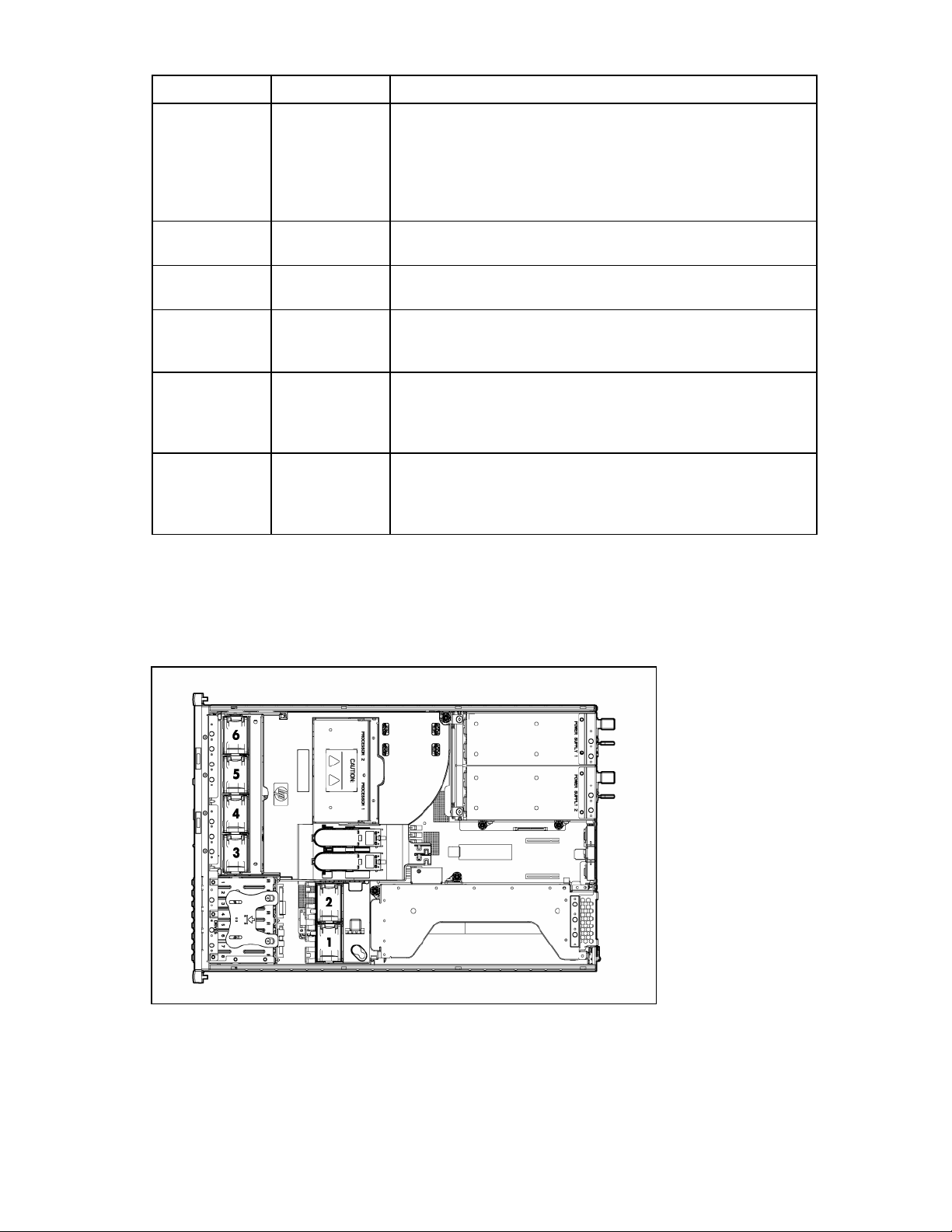
System board components (6-fan configuration)
Item Description
1 Fan board connector
2 PPM 1
3 PPM 2
4 Power supply backplane connector
5 PCIe slot 1
6 PCIe slot 2
7 NMI jumper
8 iLO 2 diagnostic LEDs
9 System maintenance switch
10 Internal USB connector*
11 System battery
12 PCI riser cage connector
13 Fan 2 connector
14 Fan 1 connector
15 FBDIMM slots (1-8)
16 Multibay interface connector
17 Processor socket 1
18 Processor socket 2
* The lower USB connector is unavailable.
Component identification 12

System board components (12-fan configuration)
Item Description
1 Fan board connector
2 PPM 1
3 PPM 2
4 Power supply backplane connector
5 PCIe slot 1
6 PCIe slot 2
7 NMI jumper
8 iLO 2 diagnostic LEDs
9 System maintenance switch
10 Internal USB connector*
11 System battery
12 PCI riser cage connector
13 Fan 4 connector
14 Fan 2 connector
15 Fan 3 connector
16 Fan 1 connector
17 FBDIMM slots (1-8)
18 Multibay interface connector
19 Processor socket 1
20 Processor socket 2
* The lower USB connector is unavailable.
Component identification 13

System maintenance switch
Position Default Function
S1 Off Off = iLO 2 security is enabled.
On = iLO 2 security is disabled.
S2 Off Off = System configuration can be modified.
On = System configuration is locked and cannot be modified.
S3 Off Reserved
S4 Off Reserved
S5 Off Off = Power-on password is enabled.
On = Power-on password is disabled.
S6 Off Off = Normal
On = ROM treats system configuration as invalid.
S7 Off Reserved
S8 Off Reserved
When the system maintenance switch position 6 is set to the On position, the system is prepared to erase
all system configuration settings from both CMOS and NVRAM.
CAUTION: Clearing CMOS and/or NVRAM deletes configuration information. Be sure to
properly configure the server or data loss could occur.
NMI functionality
An NMI crash dump enables administrators to create crash dump files when a system is hung and not
responding to traditional debug mechanisms.
Crash dump log analysis is an essential part of diagnosing reliability problems, such as hangs in
operating systems, device drivers, and applications. Many crashes freeze a system, and the only
available action for administrators is to cycle the system power. Resetting the system erases any
information that could support problem analysis, but the NMI feature preserves that information by
performing a memory dump before a hard reset.
To force the OS to invoke the NMI handler and generate a crash dump log, the administrator can do any
of the following:
• Short the NMI jumper pins
• Press the NMI switch
• Use the iLO Virtual NMI feature
For additional information, see the whitepaper on the HP website
(http://h20000.www2.hp.com/bc/docs/support/SupportManual/c00797875/c00797875.pdf
).
Component identification 14

FBDIMM slots
FBDIMM slots are numbered sequentially (1 through 8) and the paired banks are identified by the letters
A, B, C, and D.
Systems Insight Display LEDs and internal health LED combinations
When the internal health LED on the front panel illuminates either amber or red, the server is experiencing
a health event. Combinations of illuminated system LEDs and the internal health LED indicate system
status.
Systems Insight Display
LED and color
Processor failure, socket X
(amber)
PPM failure, slot X (amber) Red One or more of the following conditions may exist:
FBDIMM failure, slot X
(amber)
Internal health
LED color
Red One or more of the following conditions may exist:
Amber Processor in socket X is in a pre-failure condition.
Red FBDIMM in slot X has failed.
Amber FBDIMM in slot X is in a pre-failure condition.
Status
• Processor in socket X has failed.
• Processor X is not installed in the socket.
• Processor X is unsupported.
• ROM detects a failed processor during POST
• PPM in slot X has failed.
• PPM is not installed in slot X, but the corresponding
processor is installed.
Component identification 15

Systems Insight Display
LED and color
FBDIMM failure, all slots in
one bank (amber)
FBDIMM failure, all slots in
all banks (amber)
Online spare memory
(amber)
Online spare memory
(flashing amber)
Online spare memory (green) Green Online spare memory enabled and not failed.
Mirrored memory (amber) Amber Bank(s) X failed over to the mirrored memory bank(s).
Mirrored memory (flashing
amber)
Mirrored memory (green) Green Mirrored memory enabled and not failed.
Overtemperature (amber) Amber The Health Driver has detected a cautionary temperature
Riser interlock (amber) Red PCI riser cage is not seated.
Fan (amber) Amber One fan is failed or removed.
Internal health
Status
LED color
Red One or more FBDIMMs has failed. Test each bank of
FBDIMMs by removing all other FBDIMMs. Isolate the
failed FBDIMM by replacing each FBDIMM in a bank with
a known working FBDIMM.
Red One or more FBDIMMs has failed. Test each bank of
FBDIMMs by removing all other FBDIMMs. Isolate the
failed FBDIMM by replacing each FBDIMM in a bank with
a known working FBDIMM.
Amber Bank X failed over to the online spare memory bank.
Red Invalid online spare memory configuration.
Red Invalid mirrored memory configuration.
level.
Red The server has detected a hardware critical temperature
level.
Red Two or more fans have failed or are removed.
SAS device numbers
Component identification 16

SAS and SATA hard drive LEDs
Item Description
1 Fault/UID LED (amber/blue)
2 Online LED (green)
SAS and SATA hard drive LED combinations
Online/activity
LED (green)
On, off, or
flashing
On, off, or
flashing
On Amber, flashing
On Off The drive is online, but it is not active currently.
Flashing regularly
(1 Hz)
Flashing regularly
(1 Hz)
Fault/UID LED
Interpretation
(amber/blue)
Alternating amber and
blue
Steadily blue The drive is operating normally, and it has been selected by a
regularly (1 Hz)
Amber, flashing
regularly (1 Hz)
Off Do not remove the drive. Removing a drive may terminate the
The drive has failed, or a predictive failure alert has been
received for this drive; it also has been selected by a
management application.
management application.
A predictive failure alert has been received for this drive.
Replace the drive as soon as possible.
Do not remove the drive. Removing a drive may terminate the
current operation and cause data loss.
The drive is part of an array that is undergoing capacity
expansion or stripe migration, but a predictive failure alert has
been received for this drive. To minimize the risk of data loss,
do not replace the drive until the expansion or migration is
complete.
current operation and cause data loss.
The drive is rebuilding, or it is part of an array that is
undergoing capacity expansion or stripe migration.
Component identification 17

Online/activity
LED (green)
Flashing
irregularly
Flashing
Fault/UID LED
(amber/blue)
Amber, flashing
regularly (1 Hz)
Off The drive is active, and it is operating normally.
irregularly
Off Steadily amber A critical fault condition has been identified for this drive, and
Off Amber, flashing
regularly (1 Hz)
Off Off The drive is offline, a spare, or not configured as part of an
PCI riser cage LED
CAUTION: To prevent damage to the server or expansion boards, power down the server and
remove all AC power cords before removing or installing the PCI riser cage.
Interpretation
The drive is active, but a predictive failure alert has been
received for this drive. Replace the drive as soon as possible.
the controller has placed it offline. Replace the drive as soon as
possible.
A predictive failure alert has been received for this drive.
Replace the drive as soon as possible.
array.
Status
On = AC power connected
Off = AC power disconnected
Component identification 18

Battery pack LEDs
Item ID Color Description
1 Green System Power LED. This LED glows steadily when the
system is powered up and 12 V system power is
available. This power supply is used to maintain the
battery charge and provide supplementary power to the
cache microcontroller.
2 Green Auxiliary Power LED. This LED glows steadily when 3.3V
auxiliary voltage is detected. The auxiliary voltage is used
to preserve BBWC data and is available any time that the
system power cords are connected to a power supply.
3 Amber Battery Health LED. To interpret the illumination patterns of
this LED, see the following table.
4 Green BBWC Status LED. To interpret the illumination patterns of
this LED, see the following table.
LED3 pattern LED4 pattern Interpretation
— One blink every
two seconds
— Double blink,
then pause
The system is powered down, and the cache contains data that has
not yet been written to the drives. Restore system power as soon as
possible to prevent data loss.
Data preservation time is extended any time that 3.3 V auxiliary
power is available, as indicated by LED 2. In the absence of
auxiliary power, battery power alone preserves the data. A fullycharged battery can normally preserve data for at least two days.
The battery lifetime also depends on the cache module size. For
further information, refer to the controller QuickSpecs on the HP
website (http://www.hp.com
The cache microcontroller is waiting for the host controller to
communicate.
).
Component identification 19
LED3 pattern LED4 pattern Interpretation
— One blink per
second
— Steady glow The battery pack is fully charged, and posted write data is stored in
— Off The battery pack is fully charged, and there is no posted write data
One blink per
second
One blink per
second
Steady glow — There is a short circuit across the battery terminals or within the
One blink per
— There is an open circuit across the battery terminals or within the
second
The battery pack is below the minimum charge level and is being
charged. Features that require a battery (such as write cache,
capacity expansion, stripe size migration, and RAID migration) are
temporarily unavailable until charging is complete. The recharge
process takes between 15 minutes and two hours, depending on the
initial capacity of the battery.
the cache.
in the cache.
An alternating green and amber blink pattern indicates that the
cache microcontroller is executing from within its boot loader and
receiving new flash code from the host controller.
battery pack. BBWC features are disabled until the battery pack is
replaced. The life expectancy of a battery pack is typically more
than three years.
battery pack. BBWC features are disabled until the battery pack is
replaced. The life expectancy of a battery pack is typically more
than three years.
Hot-plug fans (6-fan configuration)
For server models that support six fans, the fan configuration operates in redundant mode when all six
fans are installed.
For more information, see "Hot-plug fan operation (on page 28)."
Component identification 20

Hot-plug fans (12-fan configuration)
For server models that support 12 fans, the fan configuration operates in redundant mode when all 12
fans are installed.
For more information, see "Hot-plug fan operation (on page 28)."
Fan board components
Item Description
1 Fan connectors (8)*
2 Systems Insight Display connector
3 Power On/Standby button/system power LED
4 UID LED button
5 USB connectors (2)
6 Video connector
Component identification 21

Item Description
7 Fan board system connector
*Only the 12-fan configuration supports all connectors.
Component identification 22

Operations
Power up the server
To power up the server, press the Power On/Standby button.
Power down the server
WARNING: To reduce the risk of personal injury, electric shock, or damage to the equipment,
remove the power cord to remove power from the server. The front panel Power On/Standby
button does not completely shut off system power. Portions of the power supply and some
1. Back up the server data.
2. Shut down the operating system as directed by the operating system documentation.
3. Press the Power On/Standby button to place the server in Standby mode. When the server activates
internal circuitry remain active until AC power is removed.
IMPORTANT: If installing a hot-plug device, it is not necessary to power down the server.
NOTE: If the operating system automatically places the server in Standby mode, omit the next
step.
Standby power mode, the system power LED changes to amber.
IMPORTANT: Pressing the UID button illuminates the blue UID LEDs on the front and rear
panels. In a rack environment, this feature facilitates locating a server when moving between
the front and rear of the rack.
4. Disconnect the power cords.
The system is now without power.
Extend the server from the rack
1. Pull down the quick release levers on each side of the server.
2. Extend the server until the server rail-release latches engage.
WARNING: To reduce the risk of personal injury or equipment damage, be sure that the rack
is adequately stabilized before extending a component from the rack.
Operations 23

3. After performing the installation or maintenance procedure, slide the server back into the rack:
a. Press the server rail-release latches and slide the server fully into rack.
WARNING: To reduce the risk of personal injury, be careful when pressing the server rail-
release latches and sliding the server into the rack. The sliding rails could pinch your fingers.
b. Press the server firmly into the rack to secure it in place.
Remove the access panel
WARNING: To reduce the risk of personal injury from hot surfaces, allow the drives and the
internal system components to cool before touching them.
CAUTION: Do not operate the server for long periods with the access panel open or removed.
Operating the server in this manner results in improper airflow and improper cooling that can
lead to thermal damage.
Operations 24

To remove the component:
1. Power down the server if performing a non-hot-plug installation or maintenance procedure ("Power
down the server" on page 23).
2. Extend the server from the rack (on page 23).
3. Use the T-15 Torx screwdriver attached to the rear of the server to loosen the security screw on the
hood latch.
4. Lift up on the hood latch handle and remove the access panel.
Install the access panel
1. Place the access panel on top of the server with the hood latch open. Allow the panel to extend past
the rear of the server approximately 1.25 cm (0.5 in).
2. Push down on the hood latch. The access panel slides to a closed position.
3. Use the T-15 Torx screwdriver attached to the rear of the server to tighten the security screw on the
hood latch.
Remove the PCI riser cage
CAUTION: To prevent damage to the server or expansion boards, power down the server and
1. Power down the server (on page 23).
2. Extend the server from the rack (on page 23).
3. Remove the access panel (on page 24).
4. Disconnect any internal or external cables connected to any existing expansion boards.
remove all AC power cords before removing or installing the PCI riser cage.
5. Press the blue button to release the black knob.
6. Turn the black knob counter-clockwise.
7. Remove the PCI riser cage.
Operations 25

Install the PCI riser cage
CAUTION: To prevent damage to the server or expansion boards, power down the server and
1. Align the PCI riser cage with the chassis and slide it into place.
2. Tighten the thumbscrews to secure the PCI riser cage:
remove all AC power cords before removing or installing the PCI riser cage.
a. Press down the black knob while turning clockwise, until fully tightened.
b. While holding the black knob and pressing down, press and release the blue button to lower the
black knob to the locked position.
3. Connect any required internal cables to the expansion board. Refer to the documentation that ships
with the expansion board.
4. Install the access panel (on page 25).
5. Install the server into the rack.
Operations 26

6.
Connect any required external cables to the expansion board. Refer to the documentation that ships
with the expansion board.
7. Power up the server (on page 23).
Access the product rear panel
Cable management arm with left-hand swing
To access the server rear panel, open the cable management arm.
Cable management arm with right-hand swing
NOTE: To access some components, you may need to remove the cable management arm.
To access the product rear panel components, open the cable management arm:
1. Power down the server (on page 23).
2. Swing open the cable management arm.
3. Remove the cables from the cable trough.
Operations 27

4.
Remove the cable management arm.
Hot-plug fan operation
The server supports variable fan speeds. The fans operate at minimum speed until a temperature change
requires a fan speed increase to cool the server.
The server shuts down in the following temperature-related scenarios:
• At POST:
o The BIOS suspends the server for 5 minutes if it detects a cautionary temperature level. If the
cautionary temperature level is still detected after 5 minutes, the BIOS performs an orderly
shutdown and enters Standby mode.
o The BIOS performs an orderly shutdown if two or more fans have failed.
o The server performs an immediate shutdown if it detects a critical temperature level.
IMPORTANT: An immediate shutdown is a hardware-controlled function and it overrides any
• In the operating system:
firmware or software actions.
o The Health Driver performs an orderly shutdown if it detects a cautionary temperature level. If the
server detects a critical temperature level before the orderly shutdown occurs, the server performs
an immediate shutdown. Additionally, the Health Driver performs an orderly shutdown if more
than one fan is failed or removed.
o When Thermal Shutdown is disabled in RBSU, the server performs an immediate shutdown if it
detects a critical temperature level.
IMPORTANT: An immediate shutdown is a hardware-controlled function and it overrides any
firmware or software actions.
Operations 28

Setup
Optional installation services
Delivered by experienced, certified engineers, HP Care Pack services help you keep your servers up and
running with support packages tailored specifically for HP ProLiant systems. HP Care Packs let you
integrate both hardware and software support into a single package. A number of service level options
are available to meet your needs.
HP Care Pack Services offer upgraded service levels to expand your standard product warranty with easyto-buy, easy-to-use support packages that help you make the most of your server investments. Some of the
Care Pack services are:
• Hardware support
o 6-Hour Call-to-Repair
o 4-Hour 24x7 Same Day
o 4-Hour Same Business Day
• Software support
o Microsoft®
o Linux
o HP ProLiant Essentials (HP SIM and RDP)
o VMWare
• Integrated hardware and software support
o Critical Service
o Proactive 24
o Support Plus
o Support Plus 24
• Startup and implementation services for both hardware and software
For more information on Care Packs, refer to the HP website
(http://www.hp.com/hps/carepack/servers/cp_proliant.html
Rack planning resources
).
The rack resource kit ships with all HP branded or Compaq branded 9000, 10000, and H9 series racks.
For more information on the content of each resource, refer to the rack resource kit documentation.
If you intend to deploy and configure multiple servers in a single rack, refer to the white paper on highdensity deployment at the HP website (http://www.hp.com/products/servers/platforms
).
Setup 29

Optimum environment
When installing the server in a rack, select a location that meets the environmental standards described in
Space and airflow requirements
this section.
To allow for servicing and adequate airflow, observe the following space and airflow requirements when
deciding where to install a rack:
• Leave a minimum clearance of 63.5 cm (25 in) in front of the rack.
• Leave a minimum clearance of 76.2 cm (30 in) behind the rack.
• Leave a minimum clearance of 121.9 cm (48 in) from the back of the rack to the back of another
rack or row of racks.
HP servers draw in cool air through the front door and expel warm air through the rear door. Therefore,
the front and rear rack doors must be adequately ventilated to allow ambient room air to enter the
cabinet, and the rear door must be adequately ventilated to allow the warm air to escape from the
cabinet.
CAUTION: To prevent improper cooling and damage to the equipment, do not block the
ventilation openings.
When vertical space in the rack is not filled by a server or rack component, the gaps between the
components cause changes in airflow through the rack and across the servers. Cover all gaps with
blanking panels to maintain proper airflow.
CAUTION: Always use blanking panels to fill empty vertical spaces in the rack. This
arrangement ensures proper airflow. Using a rack without blanking panels results in improper
cooling that can lead to thermal damage.
The 9000 and 10000 Series Racks provide proper server cooling from flow-through perforations in the
front and rear doors that provide 64 percent open area for ventilation.
CAUTION: When using a Compaq branded 7000 Series rack, you must install the high
airflow rack door insert [P/N 327281-B21 (42U) or P/N 157847-B21 (22U)] to provide
proper front-to-back airflow and cooling.
CAUTION: If a third-party rack is used, observe the following additional requirements to ensure
adequate airflow and to prevent damage to the equipment:
• Front and rear doors—If the 42U rack includes closing front and rear doors, you must allow
5,350 sq cm (830 sq in) of holes evenly distributed from top to bottom to permit adequate
airflow (equivalent to the required 64 percent open area for ventilation).
• Side—The clearance between the installed rack component and the side panels of the rack
must be a minimum of 7 cm (2.75 in).
IMPORTANT: The HP ProLiant DL380 Generation 5 Server cable management arm is not
supported on Compaq branded 7000 series racks.
Setup 30
 Loading...