

Page 1

HP ProBook 4340s Notebook PC
HP ProBook 4341s Notebook PC
Maintenance and Service Guide
Page 2

© Copyright 2012 Hewlett-Packard
Development Company, L.P.
Bluetooth is a trademark owned by its
proprietor and used by Hewlett-Packard
Company under license. Intel and Core are
trademarks or registered trademarks of Intel
Corporation in the United States and other
countries. Microsoft and Windows are either
trademarks or registered trademarks of
Microsoft Corporation in the United States
and/or other countries. SD Logo is a
trademark of its proprietor.
The information contained herein is subject
to change without notice. The only
warranties for HP products and services are
set forth in the express warranty statements
accompanying such products and services.
Nothing herein should be construed as
constituting an additional warranty. HP shall
not be liable for technical or editorial errors
or omissions contained herein.
First Edition: May 2012
Document Part Number: 679212-001
Page 3

Safety warning notice
WARNING! To reduce the possibility of heat-related injuries or of overheating the computer, do not
place the computer directly on your lap or obstruct the computer air vents. Use the computer only on
a hard, flat surface. Do not allow another hard surface, such as an adjoining optional printer, or a soft
surface, such as pillows or rugs or clothing, to block airflow. Also, do not allow the AC adapter to
contact the skin or a soft surface, such as pillows or rugs or clothing, during operation. The computer
and the AC adapter comply with the user-accessible surface temperature limits defined by the
International Standard for Safety of Information Technology Equipment (IEC 60950).
iii
Page 4

iv Safety warning notice
Page 5

Table of contents
1 Product description ........................................................................................................................................ 1
2 External component identification ................................................................................................................ 6
Display .................................................................................................................................................. 6
Top ....................................................................................................................................................... 7
TouchPad ............................................................................................................................ 7
Lights ................................................................................................................................... 8
Buttons, speakers, and fingerprint reader (select models only) ........................................... 9
Keys ................................................................................................................................... 10
Front ................................................................................................................................................... 11
Left ..................................................................................................................................................... 12
Right ................................................................................................................................................... 13
3 Illustrated parts catalog ............................................................................................................................... 14
Service tag ......................................................................................................................................... 14
Computer major components ............................................................................................................. 15
Display components ........................................................................................................................... 18
Plastics Kit .......................................................................................................................................... 18
Mass storage devices ......................................................................................................................... 19
Miscellaneous parts ............................................................................................................................ 20
Sequential part number listing ............................................................................................................ 21
4 Removal and replacement procedures ....................................................................................................... 25
Preliminary replacement requirements ............................................................................................... 25
Tools required .................................................................................................................... 25
Service considerations ....................................................................................................... 25
Plastic parts ....................................................................................................... 25
Cables and connectors ..................................................................................... 26
Drive handling ................................................................................................... 26
Grounding guidelines ......................................................................................................... 27
Electrostatic discharge damage ........................................................................ 27
v
Page 6

Packaging and transporting guidelines ............................................. 28
Workstation guidelines ..................................................................... 28
Equipment guidelines ....................................................................... 29
Component replacement procedures ................................................................................................. 30
Service tag ......................................................................................................................... 30
Battery ............................................................................................................................... 31
Using the optional security screw ...................................................................................... 32
Bottom door ....................................................................................................................... 33
SIM .................................................................................................................................... 34
Optical drive ....................................................................................................................... 35
Hard drive .......................................................................................................................... 37
Memory modules ............................................................................................................... 39
WWAN module .................................................................................................................. 41
WLAN/Bluetooth combo card ............................................................................................ 43
Keyboard ........................................................................................................................... 45
Top cover ........................................................................................................................... 47
Fingerprint reader board .................................................................................................... 52
Audio board ....................................................................................................................... 54
Function board/Power button board .................................................................................. 56
RTC battery ....................................................................................................................... 58
Speaker assembly ............................................................................................................. 59
Latch assembly .................................................................................................................. 60
System board ..................................................................................................................... 61
Heat sink ............................................................................................................................ 63
Processor ........................................................................................................................... 66
Display assembly ............................................................................................................... 69
Power connector ................................................................................................................ 77
5 Computer Setup (BIOS) and Advanced System Diagnostics ................................................................... 79
Using Computer Setup ....................................................................................................................... 79
Starting Computer Setup ................................................................................................... 79
Navigating and selecting in Computer Setup ..................................................................... 79
Restoring factory settings in Computer Setup ................................................................... 80
Updating the BIOS ............................................................................................................. 81
Downloading SoftPaqs to update the BIOS ...................................................... 81
BIOS management using system diagnostics ................................................... 81
Using f10 setup to update the BIOS .................................................................. 81
Determining the BIOS version ........................................................................... 82
Downloading a BIOS update ............................................................................. 83
BIOS Setup Menu .............................................................................................................. 83
Main menu ........................................................................................................ 84
vi
Page 7

Security menu ................................................................................................... 84
Diagnostics menu .............................................................................................. 84
Using Advanced System Diagnostics ................................................................................................. 84
6 Specifications ................................................................................................................................................ 86
Computer specifications ..................................................................................................................... 86
33.8-cm (13.3-in), HD display specifications ...................................................................................... 87
Hard drive specifications .................................................................................................................... 88
DVD±RW and CD-RW SuperMulti DL Combo Drive specifications ................................................... 89
Blu-ray ROM DVD±RW SuperMulti DL Drive ..................................................................................... 90
Specification information in Device Manager ..................................................................................... 91
7 Backup and recovery .................................................................................................................................... 92
Creating recovery media with HP Recovery Disc Creator .................................................................. 93
Creating recovery media .................................................................................................... 93
Backing up your information ............................................................................................................... 94
Performing a system recovery ............................................................................................................ 95
Using the Windows recovery tools ..................................................................................... 95
Using f11 recovery tools .................................................................................................... 96
Using a Windows 7 operating system DVD (purchased separately) ................................. 96
8 Power cord set requirements ...................................................................................................................... 98
Requirements for all countries and regions ........................................................................................ 98
Requirements for specific countries and regions ............................................................................... 99
9 Recycling ..................................................................................................................................................... 101
Battery .............................................................................................................................................. 101
Display .............................................................................................................................................. 101
Index ................................................................................................................................................................. 107
vii
Page 8

viii
Page 9

1 Product description
Category Description
Product Name HP ProBook 4340s Notebook PC
HP ProBook 4341s Notebook PC
Processors Intel® Core™ i7 processor, Quad Core (6-GB L3 cache)
3612QM, 2.10-GHz processor
Intel Core i5 processors, Dual Core (3-MB L3 cache)
3360M, 2.80-GHz processor
3320M, 2.60-GHz processor
Intel Core i3 processors (3-MB L3 cache)
3110M, 2.40-GHz processor
2450M, 2.50-GHz processor
2370M, 2.40-GHz processor
2350M, 2.30-GHz processor
Intel Pentium processor, Dual Core (2-MB L3 cache)
B980, 2.40-GHz processor
B970, 2.30-GHz processor
Intel Celeron processor (2-MB L3 cache)
B840, 1.90-GHz processor
Chipset Mobile Intel HM76 chipset
Graphics Intel HD Graphics (UMA)
AMD Radeon™ HD 7570M, 1-GB (discrete)
Panel All display assemblies include 2 wireless local area network (WLAN) antennas
33.8-cm (13.3-inch) HD, 1366x768, includes camera
Memory Two customer-accessible/upgradeable memory module slots supporting up to 8 GB
of RAM
Supports dual-channel memory
PC3-10600, 1333-MHz, DDR3
1
Page 10

Category Description
Supports the following configurations:
● 8192 (4096 × 2; dual channel)
6144 (4096 + 2048; dual channel)
●
4096 (2048 × 2; dual channel)
●
● 4096 (4096 × 1)
2048 (2048 × 1)
●
Hard drives Supports 7-mm, 6.35-cm (2.50-in) SATA hard drives with HP 3D DriveGuard
Customer-accessible
Supports the following drives:
● 500-GB, 5400-rpm
● 320-GB, 7200-rpm
● 320-GB, 5400-rpm
Fixed optical drives Supports the following 12.7-mm SATA optical drives:
DVD-ROM
●
DVD+/-RW SuperMulti DL
●
● Blu-ray ROM DVD+/-RW SuperMulti DL
Supports no optical drive option
Audio/Visual Integrated dual-array microphone (webcam models only)
Integrated mono (non-webcam models)
Stereo speakers (2)
Integrated webcam (720p HD)
Headphone and microphone jacks
Ethernet Realtek RTL8151FH-CG 10/100/1000
S3/S4/S5 wake on LAN (AC mode only)
Wireless Integrated WLAN options by way of wireless module:
Two WLAN antennas built into display assembly
Supports “no WLAN/No BT” option
Supports the following WLAN formats:
Ralink 802.11 b/g/n 1×1
●
Atheros 802.11 b/g/n 1×1
●
● Atheros 802.11 b/g/n + BT Combo
2 Chapter 1 Product description
Broadcom 802.11 b/g/n + BT Combo
●
Intel 802.11 a/b/g/n 2×2 + BT Combo
●
● Intel 802.11 b/g/n + BT Combo
Page 11

Category Description
Integrated WWAN options by way of wireless module:
Two WWAN antennas built into display assembly (world-wide 5 band, configured
with panels)
Subscriber identity module (SIM) security
Supports “no WWAN” option
Supports the following WWAN modules:
● Sierra MC8355 (Gobi 3000) HSPA/CDMA with GPS
Ericsson 5321 HSPA+ with GPS
●
Integrated personal area network (PAN) options by way of WLAN/Bluetooth®
Bluetooth 4.0 only supported by combo card
External media card 6-in-1 Digital Media Reader Slot
Ports Audio-in (stereo microphone)
Audio-out (stereo headphone)
RJ-45 (Ethernet, includes link and activity lights)
USB 3.0 (3)
USB 3.0 (1)
VGA (Dsub 15-pin) supporting 1600 × 1200 external resolution at 75-GHz (hot plug/
HDMI
Multi-pin AC port
Keyboard/pointing devices Full-sized keyboard
Touchpad includes: supports 2-way scroll with legend, taps enabled by default, 2-
Power requirements Smart AC adapter with localized cable plug support (3-wire plug with ground pin):
90-W
combo card:
unplug with auto-detect)
finger scrolling and zoom enabled by default
65-W
6-cell, 51-Wh Li-ion battery (In-line cavity)
Security Integrated fingerprint reader
Intel AT support
Support Kensington security lock
Support no fingerprint reader option
Operating system Preinstalled:
Windows 7 Professional 32 with Microsoft Basics (Japan only)
Windows 7 Professional 64 with Microsoft Basics
Windows 7 Home Premium 64 with Microsoft Basics
3
Page 12

Category Description
Novell™: SuSE Linux™ – SLED 11, 64-bit, SP2 (not available with WWAN)
FreeDOS
Preinstalled with Microsoft Office:
Windows 7 Professional 64 with Microsoft Office 2010 Starter (not for Japan)
Windows 7 Professional 64 with Microsoft Office 2010 Starter - PPP (EDGI)
Windows 7 Professional 64 with Microsoft Office 2010 Starter - MSNA (not for
Windows 7 Professional 64 with Microsoft Office 2010 Personal (Japan only)
Windows 7 Professional 64 with Microsoft Office 2010 Home & Business (Japan
Windows 7 Professional 64 with Microsoft Office 2010 Professional (Japan only)
Windows 7 Professional 32 with Microsoft Office 2010 Personal (Japan only)
Windows 7 Professional 32 with Microsoft Office 2010 Home & Business (Japan
Windows 7 Professional 32 with Microsoft Office 2010 Professional (Japan only)
Windows 7 Home Premium 64 with Microsoft Office 2010 Starter - PPP (EDGI)
Windows 7 Home Premium 64 with Microsoft Office 2010 Starter (not for Japan)
Windows 7 Home Premium 64 with Microsoft Office 2010 Personal (Japan only)
Windows 7 Home Premium 64 with Microsoft Office 2010 Home & Business (Japan
Windows 7 Home Premium 64 with Microsoft Office 2010 Professional (Japan only)
Windows 7 Home Basic 64 with Microsoft Office 2010 Starter - PPP (EDGI)
Windows 7 Home Basic 64 with Microsoft Office 2010 Starter (not for Japan)
Japan)
only)
only)
only)
Windows 7 Home Basic 64 with Microsoft Office 2010 Professional (Japan only)
Restore Media:
Windows 7 Professional 64
Windows 7 Professional 32
Windows 7 Home Premium 64
Windows 7 Home Basic 64
DRDVD Windows 7
Web-only support:
Windows 7 Home Basic 32
Windows 7 Home Premium 32
Windows 7 Professional 32
Windows XP Professional (discrete driver not supported)
Certified:
4 Chapter 1 Product description
Page 13

Category Description
Microsoft WHQL
Serviceability End-user replaceable parts:
AC adapter
Battery (system)
Hard drive
Memory module
Optical drive
WLAN module
WWAN module, SIM
Keyboard
5
Page 14
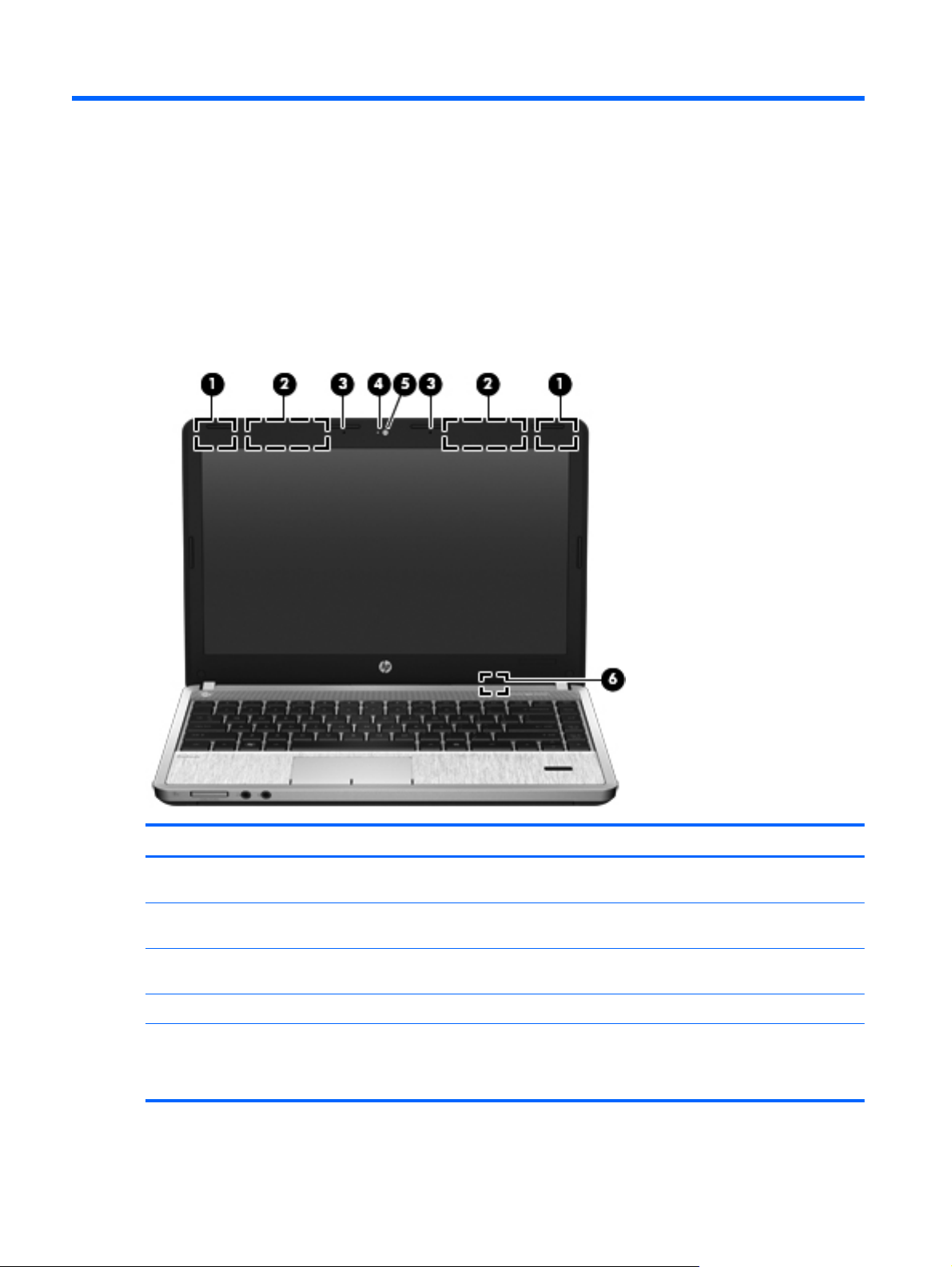
2 External component identification
Display
Component Description
(1) WWAN antennas (2)* (select models only) Send and receive wireless signals to communicate with wireless
(2) WLAN antennas (2)* Send and receive wireless signals to communicate with wireless
(3) Internal microphone(s) (1 or 2 depending on
model)
(4) Webcam light (select models only) On: The webcam is in use.
(5) Webcam (select models only) Records video and captures still photographs.
6 Chapter 2 External component identification
wide-area networks (WWAN).
local area networks (WLAN).
Record sound.
To use the webcam, select Start > All Programs > Music,
Photos and Videos>WebCam Companion.
Page 15
Component Description
(6) Internal display switch Turns off the display or initiates Sleep if the display is closed
*The antennas are not visible from the outside of the computer. For optimal transmission, keep the areas immediately
around the antennas free from obstructions. To see wireless regulatory notices, refer to the section of the Regulatory, Safety,
and Environmental Notices that applies to your country or region. These notices are located in Help and Support.
Top
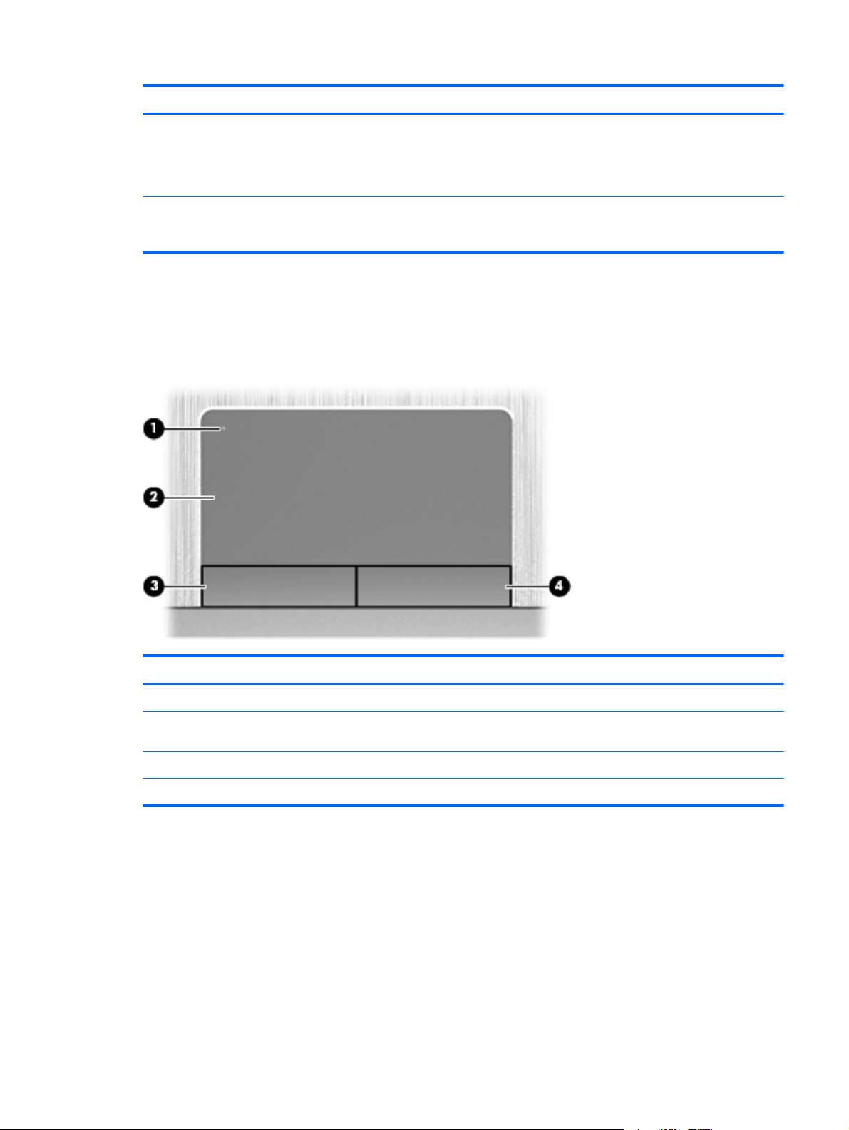
TouchPad
while the power is on.
NOTE: The display switch is not visible from the outside of the
computer.
Component Description
(1) TouchPad on/off button Turns the TouchPad on and off.
(2) TouchPad zone Moves the pointer and selects or activates items on the
(3) Left TouchPad button Functions like the left button on an external mouse.
(4) Right TouchPad button Functions like the right button on an external mouse.
screen.
Top 7
Page 16
Lights
Component Description
(1)
(2) Caps lock light On: Caps lock is on.
(3)
(4)
(5) TouchPad light
Power light
Web browser light
Wireless light
On: The computer is on.
●
● Blinking: The computer is in the Sleep state.
● Off: The computer is off or in Hibernation.
On: The computer is on.
●
● Off: The computer is off, in Suspend mode, or in
Hibernation.
White: An integrated wireless device, such as a
●
wireless local area network (WLAN) device and/or a
Bluetooth® device, is on.
Amber: All wireless devices are off.
●
Amber: The TouchPad is off.
●
● Off: The TouchPad is on.
8 Chapter 2 External component identification
Page 17
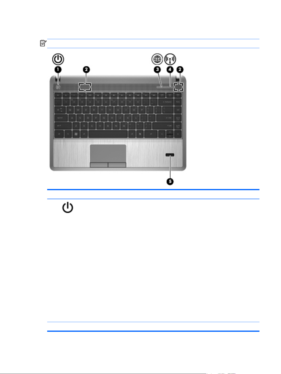
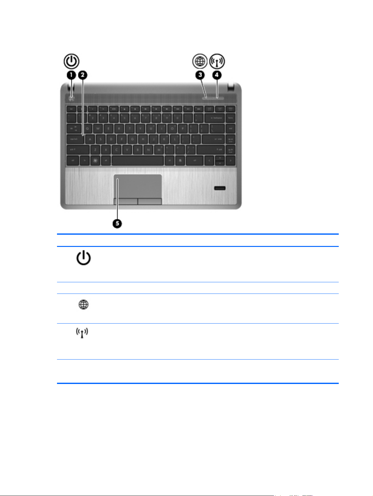
Buttons, speakers, and fingerprint reader (select models only)
NOTE: Refer to the illustration that most closely matches your computer.
Component Description
(1)
(2) Speakers (2) Produce sound.
Power button
When the computer is off, press the button to turn on
●
the computer.
● When the computer is on, press the button briefly to
initiate Sleep.
● When the computer is in the Sleep state, press the
button briefly to exit Sleep.
When the computer is in Hibernation, press the button
●
briefly to exit Hibernation.
If the computer has stopped responding and Microsoft®
Windows® shutdown procedures are ineffective, press and
hold the power button down for at least 5 seconds to turn off
the computer.
CAUTION: Pressing and holding down the power button
will result in the loss of unsaved information.
To learn more about your power settings:
Select Start > Control Panel > System and
●
Security > Power Options.
● Refer to the HP Notebook Reference Guide.
Top 9
Page 18
Component Description
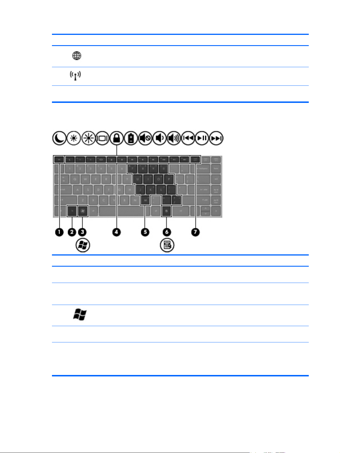
Keys
(3)
(4)
(5) Fingerprint reader (select models only) Allows a fingerprint logon to Windows, instead of a
Web browser button Opens the default Web browser.
Wireless button Turns the wireless feature on or off but does not establish a
wireless connection.
password logon.
Component Description
(1) esc key Displays system information when pressed in combination
(2) fn key Executes frequently used system functions when pressed in
(3)
(4) Function keys Execute frequently used system functions when pressed in
(5) Embedded numeric keypad keys When the keypad is turned on, it can be used like an
Windows logo key Displays the Windows Start menu.
with the fn key.
combination with a function key, the num lk key, the esc
key, or other keys.
combination with the fn key.
external numeric keypad.
Each key on the keypad performs the function indicated by
the icon in the upper-right corner of the key.
10 Chapter 2 External component identification
Page 19
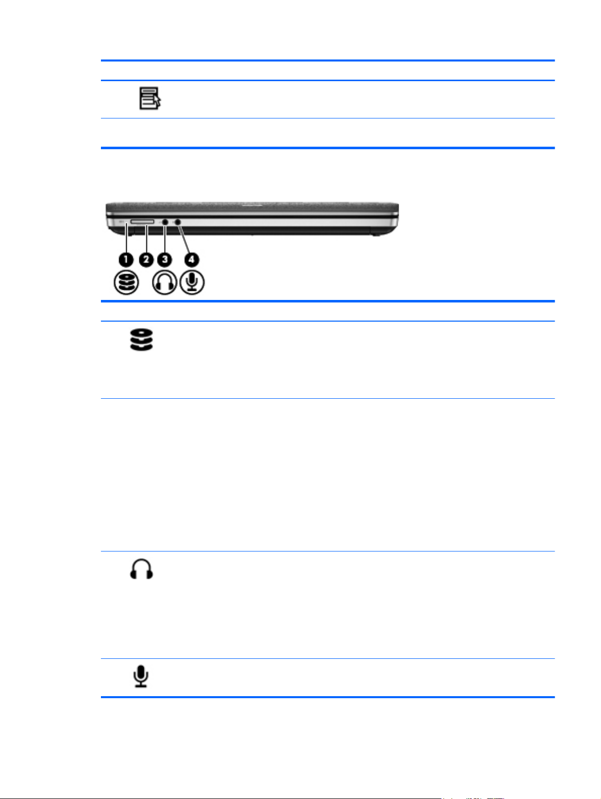
Component Description
Front
(6)
(7) num lk key Turns the embedded numeric keypad on and off when
Component Description
(1)
Windows applications key Displays a shortcut menu for items beneath the cursor.
pressed in combination with the fn key.
Drive light
White: The hard drive is being accessed.
●
● Amber: HP 3D DriveGuard has temporarily parked the
hard drive.
NOTE: For information on HP 3D DriveGuard, refer
to the HP Notebook Reference Guide.
(2) Media Card Reader Supports the following digital card formats:
● Memory Stick PRO
Memory Stick PRO Duo (needs an adapter)
●
MultiMediaCard (MMC)
●
MultiMediaCardplus (MMC+)
●
Secure Digital (SD) Card
●
Secure Digital High Capacity (SDHC) Card
●
Secure Digital Extra Capacity (SDXC) Card
●
(3)
(4)
Audio-out (headphone) jack Connects optional powered stereo speakers, headphones,
earbuds, a headset, or a television audio cable.
WARNING! To reduce the risk of personal injury, adjust
the volume before putting on headphones, earbuds, or a
headset. For additional safety information, refer to the
Regulatory, Safety, and Environmental Notices
NOTE: When a device is connected to the jack, the
computer speakers are disabled.
Audio-in (microphone) jack Connects an optional computer headset microphone, stereo
array microphone, or monaural microphone.
Front 11
Page 20
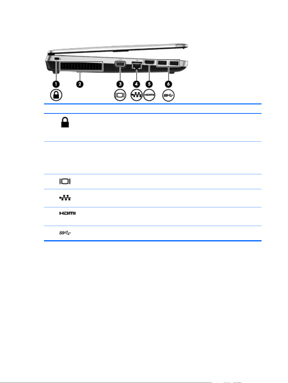
Left
Component Description
(1)
(2) Vent Enables airflow to cool internal components.
(3)
(4)
(5)
(6)
Security cable slot Attaches an optional security cable to the computer.
NOTE: The security cable is designed to act as a
deterrent, but it may not prevent the computer from being
mishandled or stolen.
NOTE: The computer fan starts up automatically to cool
internal components and prevent overheating. It is normal
for the internal fan to cycle on and off during routine
operation.
External monitor port Connects an external VGA monitor or projector.
RJ-45 (network) jack Connects a network cable.
HDMI port Connects an optional video or audio device, such as a
high-definition television, or any compatible digital or audio
device.
USB 3.0 ports (2) Connect optional USB devices. For more information about
USB devices, see the HP Notebook Reference Guide.
12 Chapter 2 External component identification
Page 21
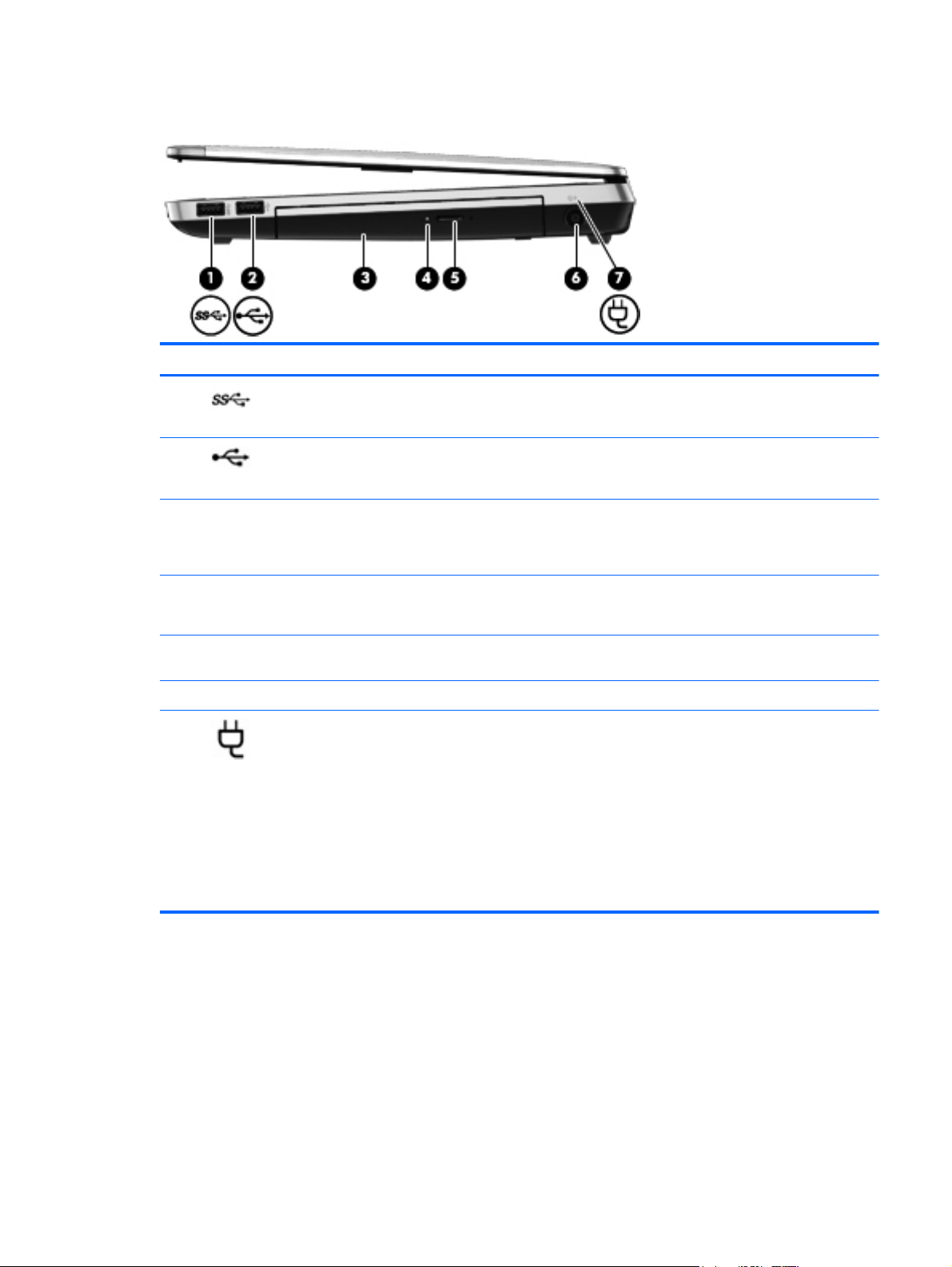
Right
Component Description
(1)
(2)
(3) Optical drive (select models only) Reads an optical disc.
(4) Optical drive light (select models only)
(5) Optical drive eject button (select models
(6) Power connector Connects an AC adapter.
(7)
USB 3.0 port Connects an optional USB device. For more information
about USB devices, see the HP Notebook Reference
Guide.
USB 2.0 port Connects an optional USB device. For more information
only)
AC adapter/battery light ● White: The computer is connected to external power
about USB devices, see the HP Notebook Reference
Guide.
NOTE: On select models, the optical drive also writes to
an optical disc.
On: The optical drive is being accessed.
●
● Off: The optical drive is idle.
Releases the optical drive disc tray.
and the battery is charged from 90 to 99 percent.
Amber: The computer is connected to external power
●
and the battery is charged from 0 to 90 percent.
Blinking amber: A battery that is the only available
●
power source has reached a low battery level. When
the battery reaches a critical battery level, the battery
light begins blinking rapidly.
Off: The battery is fully charged.
●
Right 13
Page 22
3 Illustrated parts catalog
Service tag
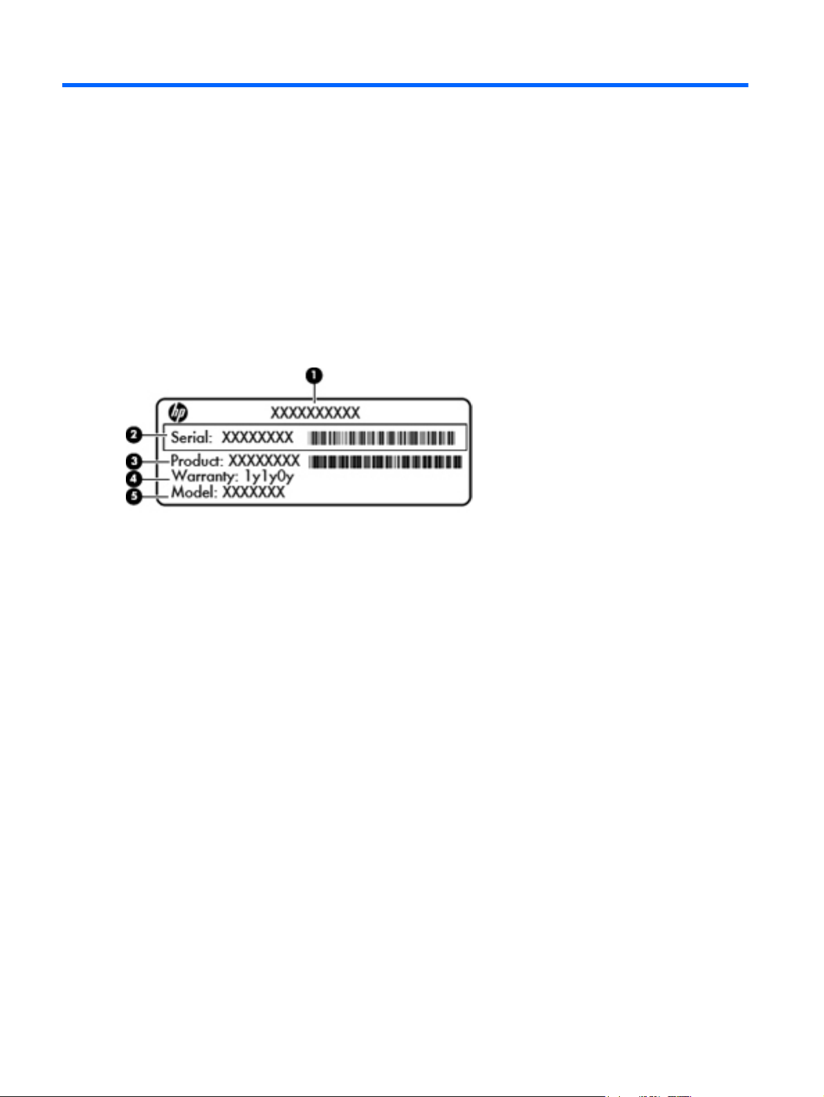
When ordering parts or requesting information, provide the computer serial number and model
description provided on the service tag.
Product name (1). This is the product name affixed to the front of the computer.
●
Serial number (s/n) (2). This is an alphanumeric identifier that is unique to each product.
●
Part number/Product number (p/n) (3). This number provides specific information about the
●
product's hardware components. The part number helps a service technician to determine what
components and parts are needed.
Warranty period (4). This number describes the duration (in years) of the warranty period for the
●
computer.
Model description (select models only) (5). This is the alphanumeric identifier used to locate
●
documents, drivers, and support for the computer.
14 Chapter 3 Illustrated parts catalog
Page 23
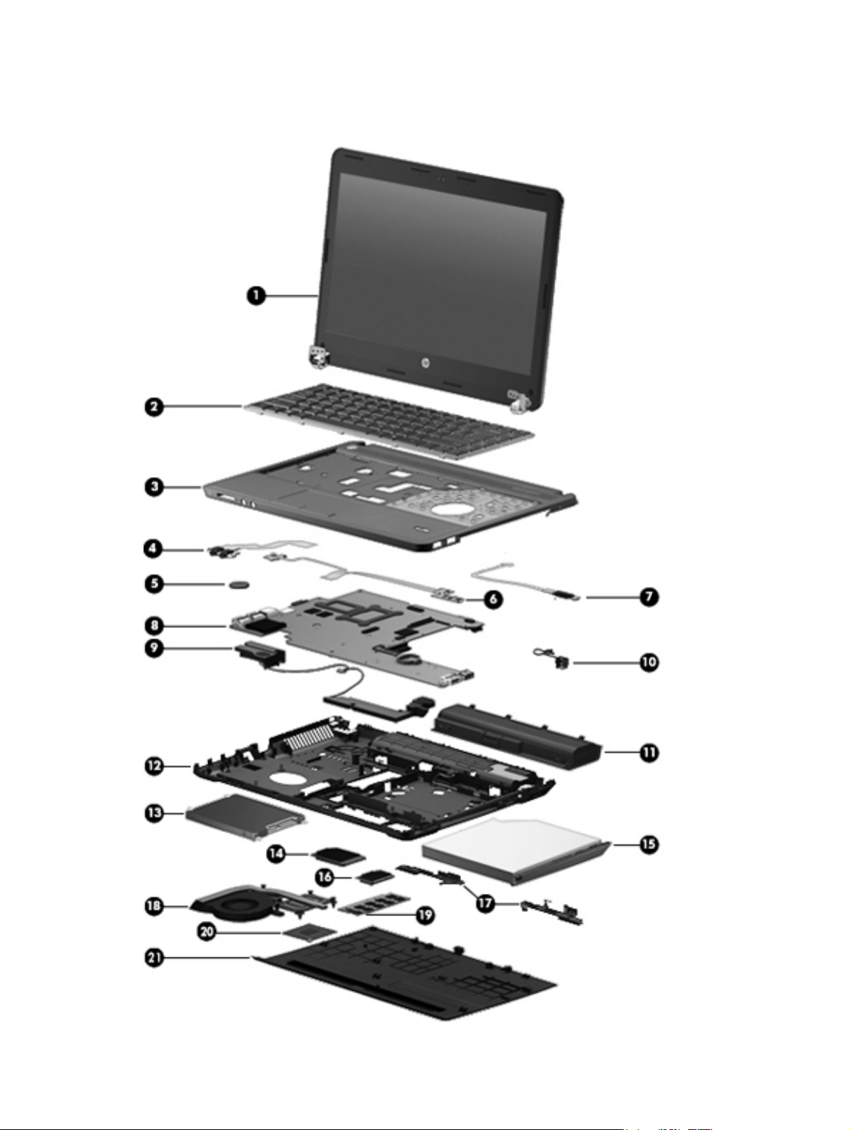
Computer major components
Computer major components 15
Page 24

Item Description Spare part number
(1) Display panel, 33.8-cm (13.3-inch) HD, anti-glare 684251-001
(2) Keyboard (includes cable)
NOTE: For a detailed list of available keyboards, see
on page 21.
(3) Top cover (includes touchpad)
For use in models with a fingerprint reader 684243-001
For use in models without a fingerprint reader 684244-001
(4) Audio board (includes cable) 684245-001
(5) RTC battery 684248-001
(6) Function board/Power button board (includes cables) 684240-001
(7) Fingerprint reader assembly (includes cable and bracket) 683862-001
(8) System board (includes replacement thermal material)
For use in models with discrete graphics 683855-001
For use in models with UMA graphics 683856-001
For use in Japan in models with UMA graphics 696335-001
(9) Speaker assembly 684242-001
(10) Power connector cable (includes bracket and screws) 683859-001
(11) Battery, Li-ion, 6-cell, 51 WHr, 2.55 Ah 669831-001
Sequential part number listing
684252-xxx
(12) Base enclosure 683857-001
(13) Hard drive
500-GB, 5400-rpm 683802-001
320-GB, 7200-rpm 634862-001
320-GB, 5400-rpm 645193-001
128-GB solid-state drive 684253-001
(14) WWAN modules
Ericsson F5321 HSPA+ with GPS 668969-001
Sierra MC8355 (Gobi3000) HSPA/CDMA 634400-001
(15) Optical drive (includes bracket, bezel, and screws)
DVD±RW Double-Layer Drive 684249-001
Blu-ray ROM DVD±RW SuperMulti DL Drive 684250-001
(16) WLAN module
Atheros 9485GN 802.11b/g/n 1x1 WiFi and 3012 Bluetooth 4.0 Combo Adapter 655795-001
Broadcom 4313GN 802.11b/g/n 1x1 WiFi and 20702 Bluetooth 4.0 Combo Adapter 657325-001
Intel Centrino Wireless-N 2230 670290-001
16 Chapter 3 Illustrated parts catalog
Page 25

Item Description Spare part number
Intel Centrino Advanced-N 6235 670292-001
Ralink WLAN Ralink Ripple3 RT5390F_802.11 b/g/n 1x1 PCIe HMC 670691-001
Atheros AR9485 802.11b/g/n 1x1 WiFi Adapter 675794-001
(17) Latch Kit (includes knob, spring, and left and right latches) 686319-001
Heat sink (includes replacement thermal material)
(18) For use in models with discrete graphics 683860-001
For use in models with UMA graphics 683861-001
(19) Memory modules
4-GB (PC3-12800, 1600-MHz, DDR3) 641369-001
2-GB (PC3-12800, 1600-MHz, DDR3) 652972-001
(20) Processor (includes replacement thermal material)
Intel Core i7 processor, quad core
3612QM, 2.1-GHz processor with 6-MB L3 cache 680647-001
Intel Core i5 processors, dual core
3360M, 2.8-GHz processor with 3-MB L3 cache 681953-001
3320M, 2.6-GHz processor with 3-MB L3 cache 681952-001
2450M, 2.5-GHz processor with 3-MB L3 cache 676359-001
Intel Core i3 processors, dual core
3110M, 2.3-GHz processor with 3-MB L3 cache 682417-001
2370M, 2.4-GHz processor with 3-MB L3 cache 677152-001
2350M, 2.3-GHz processor with 3-MB L3 cache 653340-001
Intel Pentium processor, dual core
B980, 2.4-GHz, with 2-MB L3 cache 692428-001
B970, 2.3-GHz, with 2-MB L3 cache 676785-001
Intel Celeron processor
B840, 1.9-GHz, with 2-MB L3 cache 664663-001
(21) Bottom door 691116-001
Computer major components 17
Page 26
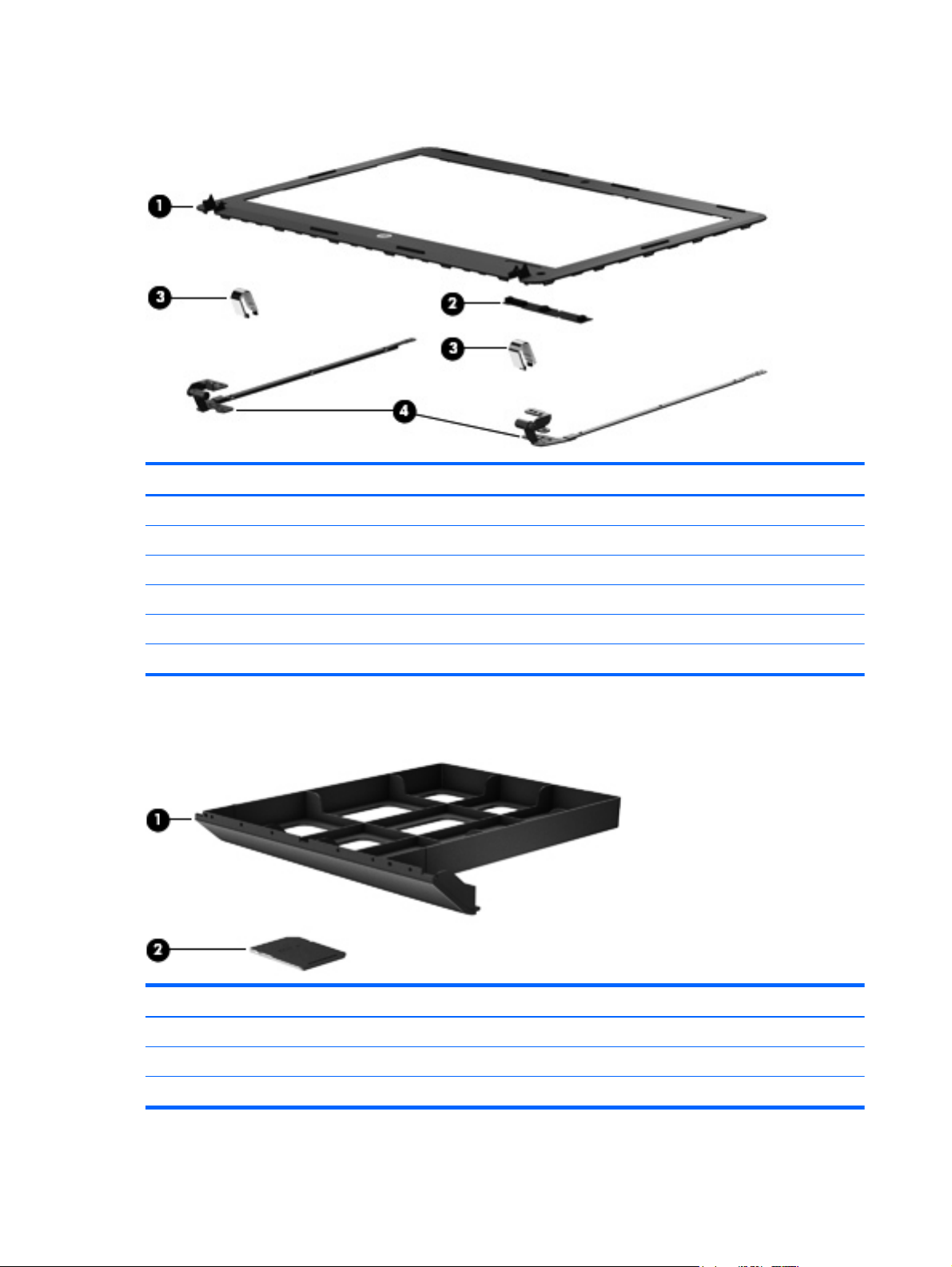
Display components
Item Description Spare part number
(1) Display bezel (includes screw covers) 683858-001
(2) Webcam module 683508-001
Display Hinge Kit 684239-001
(3) Display hinge covers (left and right)
(4) Display hinges (left and right)
Screw covers (not illustrated)
Plastics Kit
Item Description Spare part number
Plastics Kit 684241-001
(1) Optical drive protective insert
(2) Secure Digital card protective insert
18 Chapter 3 Illustrated parts catalog
Page 27
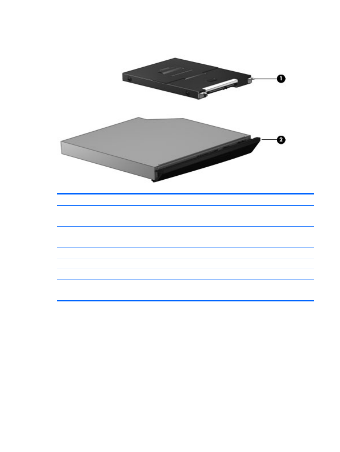
Mass storage devices
Description Spare part number
(1) Hard drives
500-GB, 5400-rpm 683802-001
320-GB, 7200-rpm 634862-001
320-GB, 5400-rpm 645193-001
128-GB solid-state drive 684253-001
Hard Drive Hardware Kit (includes hard drive bracket and screws) 684238-001
(2) Optical drives (include bezel, bracket, and screws)
DVD±RW Double-Layer Drive 684249-001
Blu-ray ROM DVD±RW SuperMulti DL Drive 684250-001
Mass storage devices 19
Page 28

Miscellaneous parts
Description Spare part number
Notebook combination lock 591699-001
Cases
Basic carrying case 455084-001
Professional slim, top load case 592923-001
Nylon case 612757-001
Mice
Mouse, optical 390632-001
Mouse, optical, travel 434594-001
AC adapters
65-W AC adapter 693711-001
65-W AC adapter for use in India and the People's Republic of China 693710-001
90-W AC adapter 693712-001
90-W AC adapter for use in India and the People's Republic of China 693713-001
Power cords:
For use in Australia 490371-011
For use in the People's Republic of China 490371-AA1
For use in Europe, the Middle East, and Africa 490371-021
For use in India 490371-D61
For use in Israel 490371-BB1
For use in Japan 490371-291
For use in South Africa 490371-AR1
For use in South Korea 490371-AD1
For use in Switzerland 490371-111
For use in Taiwan 490371-AB1
For use in Thailand 490371-201
For use in the United Kingdom 490371-031
For use in the United States 490371-001
Rubber Kit (includes bezel screw covers and base enclosure screw plugs) 684246-001
Screw Kit 684247-001
20 Chapter 3 Illustrated parts catalog
Page 29

Sequential part number listing
CSR flag designations:
A = Mandatory
B = Optional
C = Service technician recommended
N = Non-user replaceable
Spare part
number
390632-001 A Mouse, optical
434594-001 A Mouse, optical, travel
455084-001 A Basic carrying case
490371-001 A Power cord for use in North America
490371-011 A Power for cord use in Australia
490371-021 A Power for cord use in Europe, the Middle East, and Africa
490371-031 A Power cord for use in the United Kingdom
490371-111 A Power for cord use in Switzerland
490371-201 A Power cord for use in Thailand
490371-291 A Power for cord use in Japan
490371-AA1 A Power for cord use in the People's Republic of China
490371-AB1 A Power for cord use in Taiwan
490371-AD1 A Power for cord use in South Korea
490371-AR1 A Power for cord use in South Africa
490371-BB1 A Power cord for use in Israel
CSR
flag
Description
490371-D61 A Power cord for use in India
591699-001 A Notebook combination lock
592923-001 A Professional slim, top load case
612757-001 A Nylon case
634400-001 A Sierra MC8355 (Gobi3000) HSPA/CDMA
634862-001 A 320-GB, 7200-rpm hard drive, 7 mm
641369-001 A 4-GB memory module (PC3-12800, 1600-MHz, DDR3)
645193-001 A 320-GB, 5400-rpm hard drive, 7 mm
652972-001 A 2-GB memory module (PC3-12800, 1600-MHz, DDR3)
653340-001 N Intel Core i3 processor, 2350M, 2.3-GHz processor, 3-MB L3 cache (includes thermal material)
655795-001 A Atheros 9485GN 802.11b/g/n 1x1 WiFi and 3012 Bluetooth 4.0 Combo Adapter
Sequential part number listing 21
Page 30

Spare part
number
657325-001 A Broadcom 4313GN 802.11b/g/n 1x1 WiFi and 20702 Bluetooth 4.0 Combo Adapter
664663-001 N Intel Celeron B840 processor, 1.9-GHz processor, 3-MB L3 cache (includes thermal material)
668969-001 A Ericsson F5321 HSPA+ with GPS
669831-001 A 6-cell, 51 WHr, 2.55 Ah Li-ion battery
670290-001 A Intel Centrino Wireless-N 2230 WLAN card
670292-001 A Intel Centrino Advanced-N 6235 WLAN card
670691-001 A Ralink WLAN Ralink Ripple3 RT5390F_802.11 b/g/n 1x1 PCIe HMC
675794-001 A Atheros AR9485 802.11b/g/n 1x1 WiFi Adapter
676359-001 N Intel Core i5 processor, 2450M, 2.5-GHz, 3-MB L3 cache (includes thermal material)
676785-001 N Intel Pentium processor, B970, 2.3-GHz, 2-MB L3 cache (includes thermal material)
677152-001 N Intel Core i3 processor, 2370M, 2.4-GHz, 3-MB L3 cache (includes thermal material)
680647-001 N Intel Core i7 processor, 3612QM, 2.1-GHz, 6-MB L3 cache (include thermal material)
681952-001 N Intel Core i5 processor, 3320M, 2.6-GHz, 3-MB L3 cache (include thermal material)
681953-001 N Intel Core i5 processor, 3360M, 2.8-GHz, 3-MB L3 cache (include thermal material)
682417-001 N Intel Core i3 processor, 3110M, 2.3-GHz, 3-MB L3 cache (include thermal material)
CSR
flag
Description
683508-001 N Webcam module
683802-001 A 500-GB, 5400-rpm hard drive, 7 mm
683855-001 N System board for use in models with discrete graphics (includes replacement thermal material)
683856-001 N System board for use in models with UMA graphics (includes replacement thermal material)
683857-001 N Base enclosure
683858-001 N Display bezel (includes screw covers)
683859-001 N Power connector cable (includes bracket and screws)
683860-001 N Heat sink for use in models with discrete graphics (includes replacement thermal material)
683861-001 N Heat sink for use in models with UMA graphics (includes replacement thermal material)
683862-001 N Fingerprint reader assembly (includes cable)
684238-001 N Hard Drive Hardware Kit (includes hard drive bracket and screws)
684239-001 N Display Hinge Kit (includes left and right display hinges, left and right display hinge covers, bezel
screw covers, and screws)
684240-001 N Function board/Power button board (includes cable)
684241-001 N Plastics Kit (includes optical drive protective insert and Secure Digital card protective insert)
684242-001 N Speaker assembly
684243-001 N Top cover for use in models with a fingerprint reader (includes touchpad)
684244-001 N Top cover for use in models without a fingerprint reader (includes touchpad)
684245-001 N Audio board (includes cable)
22 Chapter 3 Illustrated parts catalog
Page 31

Spare part
number
684246-001 N Rubber Kit (includes bezel screw covers and base enclosure screw plugs)
684247-001 N Screw Kit
684248-001 N RTC battery
684249-001 A DVD±RW Double-Layer Drive (includes bezel, bracket, and screws)
684250-001 A Blu-ray ROM DVD±RW SuperMulti DL Drive (includes bezel, bracket, and screws)
684251-001 N Display panel, 33.8-cm (13.3-inch), anti-glare
684252-001 A Keyboard for use in the United States
684252-031 A Keyboard for use in the United Kingdom
684252-041 A Keyboard for use in Germany
684252-051 A Keyboard for use in France
684252-061 A Keyboard for use in Italy
684252-071 A Keyboard for use in Spain
684252-131 A Keyboard for use inPortugal
684252-141 A Keyboard for use in Turkey
684252-151 A Keyboard for use in Greece
CSR
flag
Description
684252-171 A Keyboard for use in Saudi Arabia
684252-211 A Keyboard for use in Hungary
684252-251 A Keyboard for use in Russia
684252-261 A Keyboard for use in Bulgaria
684252-271 A Keyboard for use in Romania
684252-281 A Keyboard for use in Thailand
684252-291 A Keyboard for use in Japan
684252-A41 A Keyboard for use in Belgium
684252-AB1 A Keyboard for use in Taiwan
684252-AD1 A Keyboard for use in South Korea
684252-B31 A Keyboard for use in the Netherlands and Europe
684252-BA1 A Keyboard for use in Slovakia
684252-BB1 A Keyboard for use in Israel
684252-BG1 A Keyboard for use in Switzerland
684252-D61 A Keyboard for use in India
684252-DD1 A Keyboard for use in Iceland
684252-DH1 A Keyboard for use in the Netherlands
684252-FL1 A Keyboard for use in the Czech Republic and Slovakia
684252-FP1 A Keyboard for use in Africa
Sequential part number listing 23
Page 32

Spare part
number
684253-001 A 128-GB solid-state drive
686319-001 N Latch Kit (includes knob, spring, and left and right latches)
691116-001 A Bottom door
692428-001 N Intel Pentium processor, B980, 2.4-GHz, 2-MB L3 cache (includes thermal material)
693710-001 A 65-W AC adapter for use in India and the People's Republic of China
693711-001 A 65-W AC adapter
693712-001 A 90-W AC adapter
693713-001 A 90-W AC adapter for use in India and the People's Republic of China
696335-001 N System board for use in Japan in models with UMA graphics
CSR
flag
Description
24 Chapter 3 Illustrated parts catalog
Page 33

4 Removal and replacement procedures
Preliminary replacement requirements
Tools required
You will need the following tools to complete the removal and replacement procedures:
● Flat-bladed screwdriver
● Phillips P0 and P1 screwdrivers
Torx T8 screwdriver
●
Service considerations
The following sections include some of the considerations that you must keep in mind during
disassembly and assembly procedures.
NOTE: As you remove each subassembly from the computer, place the subassembly (and all
accompanying screws) away from the work area to prevent damage.
Plastic parts
CAUTION: Using excessive force during disassembly and reassembly can damage plastic parts.
Use care when handling the plastic parts. Apply pressure only at the points designated in the
maintenance instructions.
Preliminary replacement requirements 25
Page 34

Cables and connectors
CAUTION: When servicing the computer, be sure that cables are placed in their proper locations
during the reassembly process. Improper cable placement can damage the computer.
Cables must be handled with extreme care to avoid damage. Apply only the tension required to
unseat or seat the cables during removal and insertion. Handle cables by the connector whenever
possible. In all cases, avoid bending, twisting, or tearing cables. Be sure that cables are routed in
such a way that they cannot be caught or snagged by parts being removed or replaced. Handle flex
cables with extreme care; these cables tear easily.
Drive handling
CAUTION: Drives are fragile components that must be handled with care. To prevent damage to
the computer, damage to a drive, or loss of information, observe these precautions:
Before removing or inserting a hard drive, shut down the computer. If you are unsure whether the
computer is off or in Hibernation, turn the computer on, and then shut it down through the operating
system.
Before handling a drive, be sure that you are discharged of static electricity. While handling a drive,
avoid touching the connector.
Before removing a diskette drive or optical drive, be sure that a diskette or disc is not in the drive and
be sure that the optical drive tray is closed.
Handle drives on surfaces covered with at least one inch of shock-proof foam.
Avoid dropping drives from any height onto any surface.
After removing a hard drive, an optical drive, or a diskette drive, place it in a static-proof bag.
Avoid exposing a hard drive to products that have magnetic fields, such as monitors or speakers.
Avoid exposing a drive to temperature extremes or liquids.
If a drive must be mailed, place the drive in a bubble pack mailer or other suitable form of protective
packaging and label the package “FRAGILE.”
26 Chapter 4 Removal and replacement procedures
Page 35

Grounding guidelines
Electrostatic discharge damage
Electronic components are sensitive to electrostatic discharge (ESD). Circuitry design and structure
determine the degree of sensitivity. Networks built into many integrated circuits provide some
protection, but in many cases, ESD contains enough power to alter device parameters or melt
silicon junctions.
A discharge of static electricity from a finger or other conductor can destroy static-sensitive devices or
microcircuitry. Even if the spark is neither felt nor heard, damage may have occurred.
An electronic device exposed to ESD may not be affected at all and can work perfectly throughout a
normal cycle. Or the device may function normally for a while, and then degrade in the internal layers,
reducing its life expectancy.
CAUTION: To prevent damage to the computer when you are removing or installing internal
components, observe these precautions:
Keep components in their electrostatic-safe containers until you are ready to install them.
Use nonmagnetic tools.
Before touching an electronic component, discharge static electricity by using the guidelines
described in this section.
Avoid touching pins, leads, and circuitry. Handle electronic components as little as possible.
If you remove a component, place it in an electrostatic-safe container.
The following table shows how humidity affects the electrostatic voltage levels generated by different
activities.
CAUTION: A product can be degraded by as little as 700 V.
Typical electrostatic voltage levels
Relative humidity
Event 10% 40% 55%
Walking across carpet 35,000 V 15,000 V 7,500 V
Walking across vinyl floor 12,000 V 5,000 V 3,000 V
Motions of bench worker 6,000 V 800 V 400 V
Removing DIPS from plastic tube 2,000 V 700 V 400 V
Removing DIPS from vinyl tray 11,500 V 4,000 V 2,000 V
Removing DIPS from Styrofoam 14,500 V 5,000 V 3,500 V
Removing bubble pack from PCB 26,500 V 20,000 V 7,000 V
Packing PCBs in foam-lined box 21,000 V 11,000 V 5,000 V
Preliminary replacement requirements 27
Page 36

Packaging and transporting guidelines
Follow these grounding guidelines when packaging and transporting equipment:
● To avoid hand contact, transport products in static-safe tubes, bags, or boxes.
Protect ESD-sensitive parts and assemblies with conductive or approved containers or
●
packaging.
● Keep ESD-sensitive parts in their containers until the parts arrive at static-free workstations.
Place items on a grounded surface before removing items from their containers.
●
Always be properly grounded when touching a component or assembly.
●
Store reusable ESD-sensitive parts from assemblies in protective packaging or nonconductive
●
foam.
Use transporters and conveyors made of antistatic belts and roller bushings. Be sure that
●
mechanized equipment used for moving materials is wired to ground and that proper materials
are selected to avoid static charging. When grounding is not possible, use an ionizer to dissipate
electric charges.
Workstation guidelines
Follow these grounding workstation guidelines:
● Cover the workstation with approved static-shielding material.
Use a wrist strap connected to a properly grounded work surface and use properly grounded
●
tools and equipment.
● Use conductive field service tools, such as cutters, screwdrivers, and vacuums.
When fixtures must directly contact dissipative surfaces, use fixtures made only of static-safe
●
materials.
● Keep the work area free of nonconductive materials, such as ordinary plastic assembly aids and
Styrofoam.
● Handle ESD-sensitive components, parts, and assemblies by the case or PCM laminate. Handle
these items only at static-free workstations.
Avoid contact with pins, leads, or circuitry.
●
● Turn off power and input signals before inserting or removing connectors or test equipment.
28 Chapter 4 Removal and replacement procedures
Page 37

Equipment guidelines
Grounding equipment must include either a wrist strap or a foot strap at a grounded workstation.
● When seated, wear a wrist strap connected to a grounded system. Wrist straps are flexible
straps with a minimum of one megohm ±10% resistance in the ground cords. To provide proper
ground, wear a strap snugly against the skin at all times. On grounded mats with banana-plug
connectors, use alligator clips to connect a wrist strap.
When standing, use foot straps and a grounded floor mat. Foot straps (heel, toe, or boot straps)
●
can be used at standing workstations and are compatible with most types of shoes or boots. On
conductive floors or dissipative floor mats, use foot straps on both feet with a minimum of one
megohm resistance between the operator and ground. To be effective, the conductive strips
must be worn in contact with the skin.
The following grounding equipment is recommended to prevent electrostatic damage:
Antistatic tape
●
Antistatic smocks, aprons, and sleeve protectors
●
Conductive bins and other assembly or soldering aids
●
Nonconductive foam
●
● Conductive tabletop workstations with ground cords of one megohm resistance
● Static-dissipative tables or floor mats with hard ties to the ground
Field service kits
●
Static awareness labels
●
Material-handling packages
●
Nonconductive plastic bags, tubes, or boxes
●
● Metal tote boxes
● Electrostatic voltage levels and protective materials
The following table lists the shielding protection provided by antistatic bags and floor mats.
Material Use Voltage protection level
Antistatic plastic Bags 1,500 V
Carbon-loaded plastic Floor mats 7,500 V
Metallized laminate Floor mats 5,000 V
Preliminary replacement requirements 29
Page 38

Component replacement procedures
This chapter provides removal and replacement procedures.
There are as many as 95 screws and screw locks, in 15 different sizes, that must be removed,
replaced, or loosened when servicing the computer. Make special note of each screw and screw lock
size and location during removal and replacement.
Service tag
When ordering parts or requesting information, provide the computer serial number and model
description provided on the service tag.
Product name (1). This is the product name affixed to the front of the computer.
●
Serial number (s/n) (2). This is an alphanumeric identifier that is unique to each product.
●
Part number/Product number (p/n) (3). This number provides specific information about the
●
product's hardware components. The part number helps a service technician to determine what
components and parts are needed.
Warranty period (4). This number describes the duration (in years) of the warranty period for the
●
computer.
Model description (select models only) (5). This is the alphanumeric identifier used to locate
●
documents, drivers, and support for the computer.
30 Chapter 4 Removal and replacement procedures
Page 39

Battery
Description Spare part number
6-cell, 51 WHr, 2.55 Ah Li-ion battery 669831-001
Before disassembling the computer, follow these steps:
1. Shut down the computer. If you are unsure whether the computer is off or in Hibernation, turn
the computer on, and then shut it down through the operating system.
2. Disconnect all external devices connected to the computer.
3. Disconnect the power from the computer by first unplugging the power cord from the AC outlet,
and then unplugging the AC adapter from the computer.
Remove the battery:
1. Position the computer upside-down on a flat surface.
2. Slide the battery release latches (1) to release the battery.
NOTE: You can slide the battery release latches simultaneously or one at a time.
3. Tilt the battery upward (2) to remove it from the battery bay (3).
Install the battery by inserting it into the battery bay until you hear a click.
Component replacement procedures 31
Page 40

Using the optional security screw
Use the optional security screw to lock the service door to the bottom of the computer. When not in
use the security screw can be stored inside the battery bay.
Remove the battery:
To use the security screw:
1. Remove the battery.
2. Remove the security screw from inside the battery bay (1) and insert it (2) to lock the service
door in place.
32 Chapter 4 Removal and replacement procedures
Page 41

Bottom door
Description Spare part number
Bottom door 691116-001
Before disassembling the computer, follow these steps:
1. Shut down the computer. If you are unsure whether the computer is off or in Hibernation, turn
the computer on, and then shut it down through the operating system.
2. Disconnect all external devices connected to the computer.
3. Disconnect the power from the computer by first unplugging the power cord from the AC outlet,
and then unplugging the AC adapter from the computer.
4. Remove the battery (see
Battery on page 31).
Remove the bottom door:
1. Position the computer upside-down on a flat surface, with the battery bay toward you.
2. With the battery bay toward you, remove the security screw (1) (if the security screw is being
used). For additional information about the security screw, see
Using the optional security screw
on page 32.
3. Slide the service door release latches (2) to release the service door.
NOTE: You can slide the service door release latches simultaneously or you can slide them
one at a time.
4. Slide the service door towards the front of the computer (3) and then lift it (4) away from the
computer.
Reverse the removal procedures to install the bottom door.
Component replacement procedures 33
Page 42

SIM
NOTE: This section applies only to computer models with WWAN capability.
NOTE: The SIM is provided by the end-user as a security measure for the WWAN module. The SIM
should be removed, placed into a static-dissipative container, and then replaced when the computer
is reassembled.
Before removing the SIM, follow these steps:
1. Shut down the computer. If you are unsure whether the computer is off or in Hibernation, turn
the computer on, and then shut it down through the operating system.
2. Disconnect all external devices connected to the computer.
3. Disconnect the power from the computer by first unplugging the power cord from the AC outlet,
and then unplugging the AC adapter from the computer.
4. Remove the battery (see
5. Remove the bottom door (see
Remove the SIM:
1. Unlock the SIM holder (1).
2. Rotate the SIM holder upright (2).
3. Remove the SIM (3) from the SIM holder.
Battery on page 31).
Bottom door on page 33).
Reverse this procedure to install the SIM.
34 Chapter 4 Removal and replacement procedures
Page 43

Optical drive
NOTE: All optical drive spare part kits include an optical drive bezel, bracket, and screws.
Description Spare part number
DVD±RW Double-Layer Drive 684249-001
Blu-ray ROM DVD±RW SuperMulti DL Drive 684250-001
Before removing the optical drive, follow these steps:
1. Shut down the computer. If you are unsure whether the computer is off or in Hibernation, turn
the computer on, and then shut it down through the operating system.
2. Disconnect all external devices connected to the computer.
3. Disconnect the power from the computer by first unplugging the power cord from the AC outlet,
and then unplugging the AC adapter from the computer.
4. Remove the battery (see
5. Remove the bottom door (see
Battery on page 31).
Bottom door on page 33).
Remove the optical drive:
1. Position the computer upside-down with the right side toward you.
2. Remove the Phillips PM2.5×6.0 screw (1) that secures the optical drive to the computer.
3. Push the optical drive tab (2) to release the optical drive from the computer.
Component replacement procedures 35
Page 44

4. Remove the optical drive (3) from the computer.
Reverse this procedure to install an optical drive.
36 Chapter 4 Removal and replacement procedures
Page 45

Hard drive
NOTE: All hard drive spare part kits include a hard drive bracket and screws.
Description Spare part number
500-GB, 5400-rpm hard drive, 7 mm 683802-001
320-GB, 7200-rpm hard drive, 7 mm 634862-001
320-GB, 5400-rpm hard drive, 7 mm 645193-001
128-GB solid-state drive 684253-001
Hard Drive Hardware Kit (includes hard drive bracket and screws) 684238-001
Before disassembling the computer, follow these steps:
1. Shut down the computer. If you are unsure whether the computer is off or in Hibernation, turn
2. Disconnect all external devices connected to the computer.
3. Disconnect the power from the computer by first unplugging the power cord from the AC outlet,
the computer on, and then shut it down through the operating system.
and then unplugging the AC adapter from the computer.
4. Remove the battery (see
5. Remove the bottom door (see
Battery on page 31).
Bottom door on page 33).
NOTE: Instructions for removing the hard drive are imprinted on the service door.
Remove the hard drive:
1. Position the computer upside-down, with the battery bay toward you.
2. Remove the four Phillips PM2.5×2.5 screws (1) that secure the hard drive to the computer.
Component replacement procedures 37
Page 46

3. Pull the Mylar tab on the hard drive (2) toward the side of the computer to disengage the hard
drive from the connector, and then lift the hard drive out of the hard drive bay.
4. If it is necessary to replace the hard drive cover, lift the Mylar tab to unlock it.
5. Remove the four Phillips PM3.0×3.0 hard drive cover screws (1) that secure the cover to the
hard drive.
38 Chapter 4 Removal and replacement procedures
Page 47

6. Lift the top of the Mylar cover (2) from the drive, and then remove the cover from the hard drive
(3).
Reverse this procedure to reassemble and install the hard drive.
Memory modules
NOTE: Primary and expansion memory is installed in a stacked configuration in the bottom of the
computer.
Description Spare part number
2-GB (PC3-12800, 1600-MHz, DDR3) 652972-001
4-GB (PC3-12800, 1600-MHz, DDR3) 641369-001
Before removing the memory module, follow these steps:
1. Shut down the computer. If you are unsure whether the computer is off or in Hibernation, turn
the computer on, and then shut it down through the operating system.
2. Disconnect all external devices connected to the computer.
3. Disconnect the power from the computer by first unplugging the power cord from the AC outlet,
and then unplugging the AC adapter from the computer.
4. Remove the battery (see
5. Remove the bottom door (see
Battery on page 31).
Bottom door on page 33).
Remove the memory module:
1. Position the computer upside-down with the battery bay toward you.
2. Spread the retaining tabs (1) on each side of the memory module slot to release the memory
module. (The edge of the module opposite the slot rises away from the computer.)
Component replacement procedures 39
Page 48

3. Remove the memory module (2) by pulling the module away from the slot at an angle.
NOTE: Memory modules are designed with a notch to prevent incorrect insertion into the
memory module slot.
NOTE: The computer uses two memory sockets. The top socket houses the expansion
memory module and the bottom socket houses the primary memory module. The removal
procedure is the same for both memory sockets.
Reverse this procedure to install a memory module.
40 Chapter 4 Removal and replacement procedures
Page 49

WWAN module
CAUTION: The WWAN module and the WLAN module are not interchangeable.
Description Spare part number
Ericsson F5321 HSPA+ with GPS 668969-001
Sierra MC8355 (Gobi3000) HSPA/CDMA 634400-001
Before removing the WWAN module, follow these steps:
1. Shut down the computer. If you are unsure whether the computer is off or in Hibernation, turn
the computer on, and then shut it down through the operating system.
2. Disconnect all external devices connected to the computer.
3. Disconnect the power from the computer by first unplugging the power cord from the AC outlet,
and then unplugging the AC adapter from the computer.
4. Remove the battery (see
5. Remove the bottom door (see
Battery on page 31).
Bottom door on page 33).
Remove the WWAN module:
1. Position the computer upside-down.
2. Disconnect the WWAN antenna cables (1) from the terminals on the WWAN module.
NOTE: The red WWAN antenna cable is connected to the WWAN module “Main” terminal. The
blue WWAN antenna cable is connected to the WWAN module “Aux” terminal.
3. Remove the two Phillips PM2.5×3.0 screws (2) that secure the WWAN module to the computer.
(The edge of the module opposite the slot rises away from the computer.)
Component replacement procedures 41
Page 50

4. Remove the WWAN module (3) by pulling the module away from the slot at an angle.
NOTE: WWAN modules are designed with a notch to prevent incorrect insertion.
Figure 4-1 Removing the WWAN module
NOTE: If the WWAN antennas are not connected to the terminals on the WWAN module, the
protective sleeves must be installed on the antenna connectors, as shown in the following
illustration.
Reverse this procedure to install the WWAN module.
42 Chapter 4 Removal and replacement procedures
Page 51

WLAN/Bluetooth combo card
The computer uses a card that provides both WLAN and Bluetooth functionality.
CAUTION: The WLAN module and the WWAN module are not interchangeable.
Description Spare part number
Atheros 9485GN 802.11b/g/n 1x1 WiFi and 3012 Bluetooth 4.0 Combo Adapter 655795-001
Broadcom 4313GN 802.11b/g/n 1x1 WiFi and 20702 Bluetooth 4.0 Combo Adapter 657325-001
Intel Centrino Wireless-N 2230 670290-001
Intel Centrino Advanced-N 6235 670292-001
Ralink WLAN Ralink Ripple3 RT5390F_802.11 b/g/n 1x1 PCIe HMC 670691-001
Atheros AR9485 802.11b/g/n 1x1 WiFi Adapter 675794-001
Before removing the WLAN module, follow these steps:
1. Shut down the computer. If you are unsure whether the computer is off or in Hibernation, turn
the computer on, and then shut it down through the operating system.
2. Disconnect all external devices connected to the computer.
3. Disconnect the power from the computer by first unplugging the power cord from the AC outlet,
and then unplugging the AC adapter from the computer.
4. Remove the battery (see
5. Remove the bottom door (see
Battery on page 31).
Bottom door on page 33).
Remove the WLAN module:
1. Position the computer upside-down.
2. Disconnect the WLAN antenna cables (1) from the terminals on the WLAN module.
NOTE: The WLAN antenna cable labeled “1” connects to the WLAN module “Main” terminal
labeled “1”. The WLAN antenna cable labeled “2” connects to the WLAN module “Aux” terminal
labeled “2”. If the computer is equipped with an 802.11a/b/g/n WLAN module, the yellow WLAN
antenna cable connects to the middle terminal on the WLAN module.
3. Remove the two Phillips PM2.5×3.0 screws (2) that secure the WLAN module to the computer.
(The edge of the module opposite the slot rises away from the computer.)
Component replacement procedures 43
Page 52

4. Remove the WLAN module (3) by pulling the module away from the slot at an angle.
NOTE: WLAN modules are designed with a notch to prevent incorrect insertion.
NOTE: If the WLAN antennas are not connected to the terminals on the WLAN module, the
protective sleeves must be installed on the antenna connectors, as shown in the following
illustration.
Reverse this procedure to install the WLAN module.
44 Chapter 4 Removal and replacement procedures
Page 53

Keyboard
NOTE: For a detailed list of available keyboards, see Sequential part number listing on page 21.
Description Spare part number
Keyboard 684252-xx1
Before removing the keyboard, follow these steps:
1. Shut down the computer. If you are unsure whether the computer is off or in Hibernation, turn
2. Disconnect all external devices connected to the computer.
3. Disconnect the power from the computer by first unplugging the power cord from the AC outlet,
the computer on, and then shut it down through the operating system.
and then unplugging the AC adapter from the computer.
4. Remove the battery (see
5. Remove the bottom door (see
Battery on page 31).
Bottom door on page 33).
Remove the keyboard:
1. Position the computer upside-down with the front toward you.
2. Remove the three Phillips PM2.5×6.0 screws that secure the keyboard to the computer.
3. Position the computer right-side up with the front toward you.
4. Open the computer as far as possible.
5. Slide the keyboard downward toward the palm rest (1).
Component replacement procedures 45
Page 54

6. Lift the top of the keyboard at an angle (2), and then pull the keyboard up to remove it from the
palm rest (3).
NOTE: Only pull the keyboard up enough to release it from the computer and flip it over onto
the palm rest. Under the keyboard, the cable is connected to the system board.
7. Rotate the keyboard until it rests on the palm rest (1), and then disconnect the keyboard cable
by lifting the keyboard connector latch (2), and then disconnecting the keyboard cable from the
system board (3).
8. Remove the keyboard.
Reverse this procedure to install the keyboard.
46 Chapter 4 Removal and replacement procedures
Page 55

Top cover
NOTE: All top cover spare part kits include a touchpad.
Description Spare part number
Top cover for use in models with a fingerprint reader (includes touchpad) 684243-001
Top cover for use in models without a fingerprint reader (includes touchpad) 684244-001
Before removing the top cover, follow these steps:
1. Shut down the computer. If you are unsure whether the computer is off or in Hibernation, turn
2. Disconnect all external devices connected to the computer.
3. Disconnect the power from the computer by first unplugging the power cord from the AC outlet,
the computer on, and then shut it down through the operating system.
and then unplugging the AC adapter from the computer.
4. Remove the battery (see
Battery on page 31).
5. Remove the following components:
a. Bottom door (see
b. Hard drive (see
c. Optical drive (see
d. Keyboard (see
Bottom door on page 33).
Hard drive on page 37)
Optical drive on page 35)
Keyboard on page 45)
Remove the top cover:
1. Position the computer upside-down with the front toward you.
Component replacement procedures 47
Page 56

2. Remove the following covers and screws that secure the top cover to the computer:
(1) 4 rubber screw covers
(2) 11 Torx T8M2.5×6.0 screws
48 Chapter 4 Removal and replacement procedures
Page 57

3. Remove the following screws that secure the top cover to the computer:
(1) 3 Phillips PM2.0×2.0 screws from the battery bay
(2) 3 Phillips PM2.0×2.0 screws from the optical drive bay
4. Position the computer upright with the front toward you.
Component replacement procedures 49
Page 58

5. Disconnect the following cables from the system board:
(1) Power button/function board cable
(2) Audio board cable
(3) Fingerprint reader board cable
6. Remove the Torx T8M2.5×6.0 screw that secures the top cover to the computer.
50 Chapter 4 Removal and replacement procedures
Page 59

7. Pry up on the top of the top cover (1) to disengage it from the computer, and then remove the
top cover from the computer (2).
Reverse this procedure to install the top cover.
Component replacement procedures 51
Page 60

Fingerprint reader board
NOTE: All fingerprint reader assembly spare part kits include cable, bracket, and screws)
Description Spare part number
Fingerprint reader board (includes cable, bracket, and screws)) 683862-001
Before removing the fingerprint reader board, follow these steps:
1. Shut down the computer. If you are unsure whether the computer is off or in Hibernation, turn
the computer on, and then shut it down through the operating system.
2. Disconnect all external devices connected to the computer.
3. Disconnect the power from the computer by first unplugging the power cord from the AC outlet,
and then unplugging the AC adapter from the computer.
4. Remove the battery (see
Battery on page 31).
5. Remove the following components:
a. Bottom door (see
b. Keyboard (see
c. Top cover (see
Bottom door on page 33).
Keyboard on page 45)
Top cover on page 47)
Remove the fingerprint reader board:
1. Position the top cover upside-down.
2. Remove the Phillips PM2.0×3.0 screw (1) that secures the fingerprint reader board bracket to
the top cover.
3. Slide the bracket toward the edge of the top cover (2), and then lift it off the top cover (3).
52 Chapter 4 Removal and replacement procedures
Page 61

4. Remove the reader board and cable assembly from the top cover (4).
Reverse this procedure to install the fingerprint reader board.
Component replacement procedures 53
Page 62

Audio board
Description Spare part number
Audio board (includes cable) 684245-001
Before removing the audio board, follow these steps:
1. Shut down the computer. If you are unsure whether the computer is off or in Hibernation, turn
the computer on, and then shut it down through the operating system.
2. Disconnect all external devices connected to the computer.
3. Disconnect the power from the computer by first unplugging the power cord from the AC outlet,
and then unplugging the AC adapter from the computer.
4. Remove the battery (see
Battery on page 31).
5. Remove the following components:
a. Bottom door (see
b. Keyboard (see
c. Top cover (see
Bottom door on page 33).
Keyboard on page 45)
Top cover on page 47)
Remove the audio board:
1. Position the top cover upside-down.
2. Disconnect the audio board cable (1).
3. Remove the two Phillips PM2.0×3.0 screws (2) that secure the audio board to the top cover.
54 Chapter 4 Removal and replacement procedures
Page 63

4. Rotate the audio board upward (3) and then remove it from the top cover.
Reverse this procedure to install the audio board.
Component replacement procedures 55
Page 64

Function board/Power button board
Description Spare part number
Function board/Power button board (includes cable) 684240-001
Before removing the function board and power button board, follow these steps:
1. Shut down the computer. If you are unsure whether the computer is off or in Hibernation, turn
the computer on, and then shut it down through the operating system.
2. Disconnect all external devices connected to the computer.
3. Disconnect the power from the computer by first unplugging the power cord from the AC outlet,
and then unplugging the AC adapter from the computer.
4. Remove the battery (see
Battery on page 31).
5. Remove the following components:
a. Bottom door (see
b. Keyboard (see
c. Top cover (see
Bottom door on page 33).
Keyboard on page 45)
Top cover on page 47)
Remove the function board/power button board assembly:
1. Position the top cover upside-down.
2. Remove the three Phillips PM2.0×3.0 screws (1) that secure the boards to the top cover.
NOTE: The function board is secured with two screws. The power button board is secured with
one screw.
3. Remove the function board from the top cover (2).
56 Chapter 4 Removal and replacement procedures
Page 65

4. Remove the power button board from the top cover (3).
Reverse this procedure to install the function board/power button board.
Component replacement procedures 57
Page 66

RTC battery
Description Spare part number
RTC battery 684248-001
Before removing the RTC battery, follow these steps:
1. Shut down the computer. If you are unsure whether the computer is off or in Hibernation, turn
the computer on, and then shut it down through the operating system.
2. Disconnect all external devices connected to the computer.
3. Disconnect the power from the computer by first unplugging the power cord from the AC outlet,
and then unplugging the AC adapter from the computer.
4. Remove the battery (see
Battery on page 31).
5. Remove the following components:
a. Bottom door (see
b. Keyboard (see
c. Top cover (see
Bottom door on page 33).
Keyboard on page 45)
Top cover on page 47)
Remove the RTC battery:
1. Position the computer upright with the front toward you.
2. Use a screwdriver to loosen the battery from the slot.
3. Lift the battery from the system board.
Reverse this procedure to install the RTC battery.
58 Chapter 4 Removal and replacement procedures
Page 67

Speaker assembly
Description Spare part number
Speaker assembly 684242-001
Before removing the speaker assembly, follow these steps:
1. Shut down the computer. If you are unsure whether the computer is off or in Hibernation, turn
the computer on, and then shut it down through the operating system.
2. Disconnect all external devices connected to the computer.
3. Disconnect the power from the computer by first unplugging the power cord from the AC outlet,
and then unplugging the AC adapter from the computer.
4. Remove the battery (see
Battery on page 31).
5. Remove the following components:
a. Bottom door (see
b. Keyboard (see
c. Top cover (see
Bottom door on page 33).
Keyboard on page 45)
Top cover on page 47)
Remove the speaker assembly:
1. Position the computer upright with the front toward you.
2. Disconnect the speaker cable from the system board (1).
3. Remove the four Torx T8M2.5×6.0 screws (2) that secure the speaker assembly to the
computer.
4. Remove the tape (3) that secures the speaker cables to the computer.
Component replacement procedures 59
Page 68

5. Lift the speakers from the computer (4).
Reverse this procedure to install the speaker assembly.
Latch assembly
NOTE: The Latch Kit includes the latch, knob, and spring.
Description Spare part number
Latch Kit 686319-001
Before removing the latch assembly, follow these steps:
1. Shut down the computer. If you are unsure whether the computer is off or in Hibernation, turn
the computer on, and then shut it down through the operating system.
2. Disconnect all external devices connected to the computer.
3. Disconnect the power from the computer by first unplugging the power cord from the AC outlet,
and then unplugging the AC adapter from the computer.
4. Remove the battery (see
5. Remove the following components:
a. Bottom door (see
b. Keyboard (see
Battery on page 31).
Bottom door on page 33)
Keyboard on page 45)
c. Top cover (see
d. Speaker assembly (see
Top cover on page 47)
Speaker assembly on page 59)
60 Chapter 4 Removal and replacement procedures
Page 69

NOTE: The latch assembly includes a small spring. Note the location of the spring.
Remove the latch assembly:
1. Position the computer right-side up, with the front toward you.
2. Detach the spring hook (1) from the tab on the base enclosure (2).
3. Rotate the latch (3) and lift it from the computer.
Reverse this procedure to install the latch assembly.
System board
NOTE: All system board spare part kits include replacement thermal material.
Description Spare part number
System board for use in models with discrete graphics 683855-001
System board for use in models with UMA graphics 683856-001
System board for use in Japan in models with UMA graphics 696335-001
Before removing the system board, follow these steps:
1. Shut down the computer. If you are unsure whether the computer is off or in Hibernation, turn
the computer on, and then shut it down through the operating system.
2. Disconnect all external devices connected to the computer.
3. Disconnect the power from the computer by first unplugging the power cord from the AC outlet,
and then unplugging the AC adapter from the computer.
Component replacement procedures 61
Page 70

4. Remove the battery (see Battery on page 31).
5. Remove the following components:
a. Bottom door (see
b. Hard drive (see
c. Optical drive (see
d. Keyboard (see
e. Top cover (see
Bottom door on page 33).
Hard drive on page 37)
Optical drive on page 35)
Keyboard on page 45)
Top cover on page 47)
When replacing the system board, be sure to remove the following components from the defective
system board and install on the replacement system board:
SIM card (see
●
Memory module (see
●
WLAN module (see
●
WWAN module (see
●
SIM on page 34)
Memory modules on page 39)
WLAN/Bluetooth combo card on page 43)
WWAN module on page 41)
Remove the system board:
1. Position the computer upright with the front toward you.
2. Disconnect the display cable (1), speaker cable (2), and the power cable (3) from the system
board.
3. Remove the Phillips PM2.5×6.0 screw (1) that secures the system board to the base enclosure.
62 Chapter 4 Removal and replacement procedures
Page 71

4. Lift the right side of the system board up at an angle (2), and then lift the system board up and to
the right to remove it (3).
Reverse this procedure to install the system board.
Heat sink
NOTE: The fan and heat sink are combined into one assembly. All fan/heat sink spare part kits
contain replacement thermal material.
Description Spare part number
Heat sink for use in computers with discrete graphics 683860-001
Heat sink for use in computers with UMA graphics 683861-001
Before removing the heat sink, follow these steps:
1. Shut down the computer. If you are unsure whether the computer is off or in Hibernation, turn
2. Disconnect all external devices connected to the computer.
3. Disconnect the power from the computer by first unplugging the power cord from the AC outlet,
4. Remove the battery (see
5. Remove the following components:
the computer on, and then shut it down through the operating system.
and then unplugging the AC adapter from the computer.
Battery on page 31).
a. Bottom door (see
Bottom door on page 33).
b. Hard drive (see
c. Optical drive (see
Hard drive on page 37)
Optical drive on page 35)
d. WLAN module (see
WLAN/Bluetooth combo card on page 43)
Component replacement procedures 63
Page 72

e. WWAN module (see WWAN module on page 41)
f. Keyboard (see
g. Top cover (see
h. System board (see
Keyboard on page 45)
Top cover on page 47)
System board on page 61)
Remove the heat sink:
1. Position the system board upside-down with the front toward you.
2. To remove the UMA heat sink, skip to step 6.
3. To remove the discrete heat sink, disconnect the fan cable (1) from the system board.
4. Loosen the six captive Phillips screws (2) that secure the heat sink to the system board.
5. Lift the heat sink off the system board (3).
6. To remove the UMA heat sink, disconnect the fan cable (1) from the system board.
7. Loosen the four captive Phillips screws (2) that secure the heat sink to the system board.
64 Chapter 4 Removal and replacement procedures
Page 73

8. Lift the heat sink off the system board (3).
NOTE: For discrete models, thoroughly clean thermal material from the surfaces of the system
board components (1)(3) and the heat sink (2)(4) each time you remove the heat sink. All heat sink
and processor spare part kits include thermal material.
NOTE: For UMA models, thoroughly clean thermal material from the surface of the system board
(1) and heat sink (2) each time you remove the heat sink. All heat sink and processor spare part kits
include thermal material.
Component replacement procedures 65
Page 74

Reverse this procedure to install the heat sink.
NOTE: To properly ventilate the computer, allow at least a 7.6-cm (3-in) clearance on the left side of
the computer.
The computer uses an electric fan for ventilation. The fan is controlled by a temperature sensor and is
designed to turn on automatically when high temperature conditions exist. These conditions are
affected by high external temperatures, system power consumption, power management/battery
conservation configurations, battery fast charging, and software requirements. Exhaust air is
displaced through the ventilation grill located on the left side of the computer.
Processor
NOTE: All processor spare part kits include replacement thermal material.
Description Spare part number
Intel Core i7 processor, Quad Core
3612QM, 2.1-GHz processor with 6-MB L3 cache 680647-001
Intel Core i5 processors, Dual Core
3360M, 2.8-GHz processor with 3-MB L3 cache 681953-001
3320M, 2.6-GHz processor with 3-MB L3 cache 681952-001
2450M, 2.5-GHz processor with 3-MB L3 cache 676359-001
Intel Core i3 processors, Dual Core
3110M, 2.3-GHz processor with 3-MB L3 cache 682417-001
2370M, 2.4-GHz processor with 3-MB L3 cache 677152-001
2350M, 2.3-GHz processor with 3-MB L3 cache 653340-001
Intel Pentium processor, Dual Core
B980, 2.4-GHz, with 2-MB L3 cache 692428-001
66 Chapter 4 Removal and replacement procedures
Page 75

Description Spare part number
B970, 2.3-GHz, with 2-MB L3 cache 676785-001
Intel Celeron processor
B840, 1.9-GHz, with 2-MB L3 cache 664663-001
Before removing the processor, follow these steps:
1. Shut down the computer. If you are unsure whether the computer is off or in Hibernation, turn
the computer on, and then shut it down through the operating system.
2. Disconnect all external devices connected to the computer.
3. Disconnect the power from the computer by first unplugging the power cord from the AC outlet,
and then unplugging the AC adapter from the computer.
4. Remove the battery (see
Battery on page 31).
5. Remove the following components:
a. Bottom door (see
b. Hard drive (see
c. Optical drive (see
d. WLAN module (see
e. WWAN module (see
f. Keyboard (see
g. Top cover (see
h. System board (see
i. Heat sink (see
Bottom door on page 33)
Hard drive on page 37)
Optical drive on page 35)
WLAN/Bluetooth combo card on page 43)
WWAN module on page 41)
Keyboard on page 45)
Top cover on page 47)
System board on page 61)
Heat sink on page 63)
Remove the processor:
1. Position the system board upside-down.
2. Use a flat-bladed screwdriver to turn the processor locking screw (1) one-half turn
counterclockwise until you hear a click.
Component replacement procedures 67
Page 76

3. Lift the processor (2) straight up and remove it.
NOTE: The gold triangle (3) on the processor must be aligned with the triangle embossed on
the processor slot when you install the processor.
Reverse this procedure to install the processor.
68 Chapter 4 Removal and replacement procedures
Page 77

Display assembly
All display assemblies include WLAN antenna transceivers and cables. WWAN models include 2
WWAN antenna transceivers and cables.
Description Spare part number
Display assembly, 33.8-cm (13.3-inch) HD, anti-glare 684251-001
Before removing the display assembly, follow these steps:
1. Shut down the computer. If you are unsure whether the computer is off or in Hibernation, turn
the computer on, and then shut it down through the operating system.
2. Disconnect all external devices connected to the computer.
3. Disconnect the power from the computer by first unplugging the power cord from the AC outlet,
and then unplugging the AC adapter from the computer.
4. Remove the battery (see
Battery on page 31).
5. Remove the following components:
a. Bottom door (see
b. WLAN module (see
c. WWAN module (see
d. Keyboard (see
e. Top cover (see
f. Speakers (see
Bottom door on page 33).
WLAN/Bluetooth combo card on page 43)
WWAN module on page 41)
Keyboard on page 45)
Top cover on page 47)
Speaker assembly on page 59)
Remove the display assembly:
1. Position the computer upside down.
2. Remove the WLAN and WWAN antennas from the routing path (1) on the bottom of the
computer.
Component replacement procedures 69
Page 78

3. Pull the antennas through the hole that leads to the top of the computer (2).
4. Open the computer as far as possible.
5. Disconnect the display cable (1) from the system board and make sure the antenna cables are
all pulled through the hole (2) that routes to the bottom of the computer.
6. Remove the three Torx T8M2.5×6.0 screws (1) that secure the display to the computer.
70 Chapter 4 Removal and replacement procedures
Page 79

7. Lift the display assembly straight up and remove it (2).
CAUTION: When installing the display assembly, be sure that the wireless antenna cables are
routed and arranged properly.
Failure to properly route the antennas can result in degradation of the computer's WLAN and
WWAN performance.
Component replacement procedures 71
Page 80

8. If you need to remove the hinge covers from the display hinges, pull the hinges straight up and
off the display to remove them.
Display hinge covers are available in the Display Hinge Kit using spare part number
684239-001.
9. To replace the display bezel, remove the two screw covers (1) and the two Phillips PM2.5×4.0
screws (2) from the bottom corners of the display bezel.
72 Chapter 4 Removal and replacement procedures
Page 81

10. Flex the top (1) of the bezel, the inside edges of the left and right sides (2), and then the bottom
(3) of the bezel until it disengages from the display enclosure.
11. Remove the display bezel (4).
The bezel is available using spare part number 683858-001.
Component replacement procedures 73
Page 82

12. If it is necessary to replace the webcam module from the display enclosure, disconnect the cable
from the module (1), and then gently pull the module away from the double-sided tape on the
display enclosure (2).
The webcam module is available using spare part number 683508-001.
13. If it is necessary to replace the display hinges, remove the six Phillips PM2.5×3.0 screws that
secure the display hinges and panel to the display enclosure.
14. Remove the display hinges and panel from the display enclosure.
74 Chapter 4 Removal and replacement procedures
Page 83

15. Disconnect the display panel cable by rotating the display enclosure (1), lifting the tape (2) that
covers the connector, and disconnecting the cable from the panel (3).
16. Remove the two Phillips PM1.6×1.5 screws (1) that secure each display hinge to the display
panel.
Component replacement procedures 75
Page 84

17. Remove the display hinges (2).
Display hinges are available in the Display Hinge Kit using spare part number 684239-001.
Reverse this procedure to reassemble and install the display assembly.
76 Chapter 4 Removal and replacement procedures
Page 85

Power connector
Description Spare part number
Power connector cable (includes bracket and screws) 683859-001
Before removing the power cable, follow these steps:
1. Shut down the computer. If you are unsure whether the computer is off or in Hibernation, turn
the computer on, and then shut it down through the operating system.
2. Disconnect all external devices connected to the computer.
3. Disconnect the power from the computer by first unplugging the power cord from the AC outlet,
and then unplugging the AC adapter from the computer.
4. Remove the battery (see
Battery on page 31).
5. Remove the following components:
a. Bottom door (see
b. WLAN module (see
c. WWAN module (see
d. Keyboard (see
e. Top cover (see
f. Speakers (see
g. Display (see
Bottom door on page 33).
WLAN/Bluetooth combo card on page 43)
WWAN module on page 41)
Keyboard on page 45)
Top cover on page 47)
Speaker assembly on page 59)
Display assembly on page 69)
Remove the power cable:
1. Position the computer upright with the front toward you.
2. Remove the Phillips PM2.5×4.0 screw (1) that secures the power connector bracket to the
computer.
3. Lift the bracket (2) out of the base enclosure.
Component replacement procedures 77
Page 86

4. Remove the power cable assembly from the computer (3).
NOTE: Note the location of the cable routing channel for reassembly.
Reverse this procedure to install the power connector cable.
78 Chapter 4 Removal and replacement procedures
Page 87

5 Computer Setup (BIOS) and Advanced
System Diagnostics
Using Computer Setup
Computer Setup, or Basic Input/Output System (BIOS), controls communication between all the input
and output devices on the system (such as disk drives, display, keyboard, mouse, and printer).
Computer Setup includes settings for the types of devices installed, the startup sequence of the
computer, and the amount of system and extended memory.
NOTE: Use extreme care when making changes in Computer Setup. Errors can prevent the
computer from operating properly.
Starting Computer Setup
NOTE: An external keyboard or mouse connected to a USB port can be used with Computer Setup
only if USB legacy support is enabled.
To start Computer Setup, follow these steps:
1. Turn on or restart the computer, and then press esc while the “Press the ESC key for Startup
Menu” message is displayed at the bottom of the screen.
2. Press f10 to enter Computer Setup.
Navigating and selecting in Computer Setup
To navigate and select in Computer Setup, follow these steps:
1. Turn on or restart the computer, and then press esc while the “Press the ESC key for Startup
Menu” message is displayed at the bottom of the screen.
To select a menu or a menu item, use the tab key and the keyboard arrow keys and then
●
press enter, or use a pointing device to click the item.
● To scroll up and down, click the up arrow or the down arrow in the upper-right corner of the
screen, or use the up arrow key or the down arrow key.
● To close open dialog boxes and return to the main Computer Setup screen, press esc, and
then follow the on-screen instructions.
NOTE: You can use either a pointing device (TouchPad, pointing stick, or USB mouse) or the
keyboard to navigate and make selections in Computer Setup.
2. Press f10 to enter Computer Setup.
Using Computer Setup 79
Page 88

To exit Computer Setup menus, choose one of the following methods:
To exit Computer Setup menus without saving your changes:
●
Click the Exit icon in the lower-left corner of the screen, and then follow the on-screen
instructions.
– or –
Use the tab key and the arrow keys to select File > Ignore Changes and Exit, and then press
enter.
To save your changes and exit Computer Setup menus:
●
Click the Save icon in the lower-left corner of the screen, and then follow the on-screen
instructions.
– or –
Use the tab key and the arrow keys to select File > Save Changes and Exit, and then press
enter.
Your changes go into effect when the computer restarts.
Restoring factory settings in Computer Setup
NOTE: Restoring defaults will not change the hard drive mode.
To return all settings in Computer Setup to the values that were set at the factory, follow these steps:
1. Turn on or restart the computer, and then press esc while the “Press the ESC key for Startup
Menu” message is displayed at the bottom of the screen.
2. Press f10 to enter Computer Setup.
3. Use a pointing device or the arrow keys to select File > Restore Defaults.
4. Follow the on-screen instructions.
5. To save your changes and exit, click the Save icon in the lower-left corner of the screen, and
then follow the on-screen instructions.
– or –
Use the arrow keys to select File > Save Changes and Exit, and then press enter.
Your changes go into effect when the computer restarts.
NOTE: Your password settings and security settings are not changed when you restore the factory
settings.
80 Chapter 5 Computer Setup (BIOS) and Advanced System Diagnostics
Page 89

Updating the BIOS
The next sections describe different ways of updating the BIOS.
Downloading SoftPaqs to update the BIOS
Most BIOS updates on the HP website are packaged in compressed files called SoftPaqs.
To install BIOS updates from the HP website, follow the steps below:
1. Download the SoftPaq from the HP website.
2. Click Run, and then follow the on-screen instructions to update the BIOS.
NOTE: Some download packages contain a file named Readme.txt, which contains information
regarding installing and troubleshooting the file.
BIOS management using system diagnostics
1. Download the SoftPaq from the HP website.
NOTE: Verify that the UEFI system diagnostics is installed on your computer (or USB flash
drive).
2. Click Run, and then click Cancel at the Update/USB bootable dialog box.
3. Navigate to the folder located in
4. Locate the .bin file in the ROMpaq folder (for example, 68CDD.bin) and then copy it to the
Hewlett-Packard\BIOS\New\ folder in either the HP_Tools partition of the hard drive, or the USB
flash drive.
5. Locate the .sig file in the ROM.cab file and rename it with the same prefix as the .bin file (for
example, 68CDD.sig). Copy the renamed file to the Hewlett-Packard\BIOS\New\ folder in either
the HP_Tools partition of the hard drive, or the USB flash drive.
6. Restart the computer, and then press esc while the “Press the ESC key for Startup Menu”
message is displayed at the bottom of the screen.
7. Press f2 to enter Computer Setup.
8. Click BIOS Management from the menu and then select Update BIOS.
Using f10 setup to update the BIOS
1. Download the SoftPaq from the HP website.
NOTE: Verify that the UEFI system diagnostics is installed on your computer (or USB flash
drive).
2. Click Run, and then click Cancel at the Update/USB bootable dialog box.
3. Navigate to the folder located in
c:\swsetup that corresponds to your SoftPaq number.
c:\swsetup that corresponds to your SoftPaq number.
4. Locate the .bin file in the ROMpaq folder (for example, 68CDD.bin) and then copy it to the
Hewlett-Packard\BIOS\New\ folder in either the HP_Tools partition of the hard drive, or the USB
flash drive.
Using Computer Setup 81
Page 90

5. Locate the .sig file in the ROM.cab file and rename it with the same prefix as the .bin file (for
example, 68CDD.sig). Copy the renamed file to the Hewlett-Packard\BIOS\New\ folder in either
the HP_Tools partition of the hard drive, or the USB flash drive.
6. Restart the computer, and then press esc while the “Press the ESC key for Startup Menu”
message is displayed at the bottom of the screen.
7. Press f10 to enter Computer Setup.
8. Click Update System BIOS, and then click Accept to update the BIOS.
Determining the BIOS version
To determine whether available BIOS updates contain later BIOS versions than those currently
installed on the computer, you need to know the version of the system BIOS currently installed.
BIOS version information (also known as ROM date and System BIOS) can be displayed by pressing
fn+esc (if you are already in Windows) or by using Computer Setup.
1. Start Computer Setup.
2. Use a pointing device or the arrow keys to select File > System Information.
3. To exit Computer Setup without saving your changes, click the Exit icon in the lower-left corner
of the screen, and then follow the on-screen instructions.
– or –
Use the tab key and the arrow keys to select File > Ignore Changes and Exit, and then press
enter.
82 Chapter 5 Computer Setup (BIOS) and Advanced System Diagnostics
Page 91

Downloading a BIOS update
CAUTION: To reduce the risk of damage to the computer or an unsuccessful installation, download
and install a BIOS update only when the computer is connected to reliable external power using the
AC adapter. Do not download or install a BIOS update while the computer is running on battery
power, docked in an optional docking device, or connected to an optional power source. During the
download and installation, follow these instructions:
Do not disconnect power from the computer by unplugging the power cord from the AC outlet.
Do not shut down the computer or initiate Sleep or Hibernation.
Do not insert, remove, connect, or disconnect any device, cable, or cord.
1. Select Start > Help and Support > Maintain.
2. Follow the on-screen instructions to identify your computer and access the BIOS update you
want to download.
3. At the download area, follow these steps:
a. Identify the BIOS update that is later than the BIOS version currently installed on your
computer. Make a note of the date, name, or other identifier. You may need this information
to locate the update later, after it has been downloaded to your hard drive.
b. Follow the on-screen instructions to download your selection to the hard drive.
Make a note of the path to the location on your hard drive where the BIOS update is
downloaded. You will need to access this path when you are ready to install the update.
NOTE: If you connect your computer to a network, consult the network administrator before
installing any software updates, especially system BIOS updates.
BIOS installation procedures vary. Follow any instructions that are displayed on the screen after the
download is complete. If no instructions are displayed, follow these steps:
1. Open Windows Explorer by selecting Start > Computer.
2. Double-click your hard drive designation. The hard drive designation is typically Local Disk (C:).
3. Using the hard drive path you recorded earlier, open the folder on your hard drive that contains
the update.
4. Double-click the file that has an .exe extension (for example, filename.exe).
The BIOS installation begins.
5. Complete the installation by following the on-screen instructions.
NOTE: After a message on the screen reports a successful installation, you can delete the
downloaded file from your hard drive.
BIOS Setup Menu
The tables in this section provide an overview of the BIOS Setup menu options.
Using Computer Setup 83
Page 92

Main menu
Select To do this
System information
Security menu
Select To do this
Administrator password Control access to Setup Utility.
Power-on password Control access to your computer.
Diagnostics menu
Select To do this
Primary Hard Disk Self Test Run a quick or comprehensive self-test on the hard drive.
Memory Test Run a diagnostic test on the system memory.
View and change the system time and date.
●
● View identification information about your computer.
● View specification information about the processor,
memory size, and system BIOS.
Using Advanced System Diagnostics
Advanced System Diagnostics allows you to run diagnostic tests to determine if the computer
hardware is functioning properly. The following diagnostic tests are available in Advanced System
Diagnostics:
Start-up test—This test analyzes the main computer components that are required to start the
●
computer.
Run-in test—This test repeats the start-up test and checks for intermittent problems that the
●
start-up test does not detect.
System Tune-Up—This group of additional tests checks your computer to make sure that the
●
main components are functioning correctly. System Tune-Up runs longer and more
comprehensive tests on memory modules, hard drive SMART attributes, the hard drive surface,
the battery (and battery calibration), video memory, and the WLAN module status.
Hard disk test—This test analyzes the physical condition of the hard drive, and then checks all
●
data in every sector of the hard drive. If the test detects a damaged sector, it attempts to move
the data to a good sector.
Memory test—This test analyzes the physical condition of the memory modules. If it reports an
●
error, replace the memory modules immediately.
Battery test—This test analyzes the condition of the battery and calibrates the battery if
●
necessary. If the battery fails the test, contact support to report the issue and purchase a
replacement battery.
84 Chapter 5 Computer Setup (BIOS) and Advanced System Diagnostics
Page 93

You can view system information and error logs in the Advanced System Diagnostics window.
To start Advanced System Diagnostics:
1. Turn on or restart the computer. While the “Press the ESC key for Startup Menu” message is
displayed in the lower-left corner of the screen, press esc. When the Startup Menu is displayed,
press f2.
2. Click the diagnostic test you want to run, and then follow the on-screen instructions.
NOTE: If you need to stop a diagnostics test while it is running, press esc.
Using Advanced System Diagnostics 85
Page 94

6 Specifications
Computer specifications
Metric U.S.
Dimensions
Length 22.9 cm 9.0 in
Width 32.6 cm 12.8 in
Height (front to rear) 2.5 to 3.3 cm 1.0 to 1.3 in
Weight (equipped with optical drive, 1 SODIMM, hard drive,
WLAN module, 6 cell battery)
Input power
Operating voltage 19.0 V dc @ 4.74 A – 90 W or 18.5 V dc @ 3.5 A - 65 W
Operating current 4.74 A or 3.5 A
Temperature
Operating (not writing to optical disc) 0°C to 35°C 32°F to 95°F
Operating (writing to optical disc) 5°C to 35°C 41°F to 95°F
Nonoperating -20°C to 60°C -4°F to 140°F
Relative humidity
Operating 10% to 90%
Nonoperating 5% to 95%
Maximum altitude (unpressurized)
Operating (14.7 to 10.1 psia) -15 m to 3,048 m 50 ft to 10,000 ft
Nonoperating (14.7 to 4.4 psia) -15 m to 12,192 m -50 ft to 40,000 ft
Shock
Operating 125 g, 2 ms, half-sine
2.0 kg 4.5 lbs
Nonoperating 200 g, 2 ms, half-sine
Random vibration
Operating 0.75 g zero-to-peak, 10 Hz to 500 Hz, 0.25 oct/min sweep
86 Chapter 6 Specifications
rate
Page 95

Metric U.S.
Nonoperating 1.50 g zero-to-peak, 10 Hz to 500 Hz, 0.5 oct/min sweep rate
NOTE: Applicable product safety standards specify thermal limits for plastic surfaces. The computer operates well within
this range of temperatures.
33.8-cm (13.3-in), HD display specifications
Metric U.S.
Active diagonal size 33.8-cm 13.3-in
Resolution 1366x768 (HD)
Active area 293.38x165.02
PPI 118
Surface treatment Anti-glare
Contrast ratio 300:1 (typical) – Anti-glare
Response time 16 ms
Brightness 200 nits (typical)
Viewing angle SVA
Backlight LED
Luminance uniformity @ 13 points 1.4 (typ), 1.6 (max)
Lifetime (1/2 luminance) 12,000 hours
Color coordinate (white) (0.313, 0.329)
Color tolerance (white) +/- 0.02
Color tolerance (R, G, B) +/- 0.03
Color gamut 45% NTSC @CIE1931
33.8-cm (13.3-in), HD display specifications 87
Page 96

Hard drive specifications
320-GB*
Dimensions
Height 9.5 mm
Width 70 mm
Weight 92 g
Interface type SATA
Transfer rate 100 MB/sec
Security ATA security
Seek times (typical read, including setting)
Single track 1.5 ms
Average 13 ms
Maximum 27 ms
Logical blocks 625,142,448
Disc rotational speed 5400 rpm or 7200 rpm
Operating temperature 5°C to 55°C (41°F to 131°F)
*1 GB = 1 billion bytes when referring to hard drive storage capacity. Actual accessible capacity is less. Actual drive
specifications may differ slightly.
NOTE: Certain restrictions and exclusions apply. Contact technical support for details.
88 Chapter 6 Specifications
Page 97

DVD±RW and CD-RW SuperMulti DL Combo Drive specifications
Applicable disc Read:
CD-DA, CD+(E)G, CD-MIDI, CD-TEXT, CDROM, CD-ROM XA, MIXED MODE CD, CD-I,
CD-I Bridge (Photo-CD, Video CD),
Multisession CD (Photo-CD, CD-EXTRA,
Portfolio, CD-R, CD-RW), CD-R, CD-RW, DVDROM (DVD-5, DVD-9, DVD-10, DVD-18), DVDR, DVD-RW, DVD+R, DVD+RW, DVD-RAM
Center hole diameter 1.5 cm (0.59 in)
Disc diameter
Standard disc 12 cm (4.72 in)
Mini disc 8 cm (3.15 in)
Disc thickness 1.2 mm (0.047 in)
Track pitch 0.74 µm
Access time CD DVD
Random < 175 ms < 230 ms
Full stroke < 285 ms < 335 ms
Audio output level Line-out, 0.7 Vrms
Cache buffer 2 MB
Write:
CD-R and CD-RW
DVD+R, DVD+RW, DVD-R, DVDRW, DVD-RAM
Data transfer rate
24X CD-ROM 3,600 KB/sec
8X DVD-ROM 10,800 KB/sec
24X CD-R 3,600 KB/sec
16X CD-RW 2,400 KB/sec
8X DVD+R 10,800 KB/sec
4X DVD+RW 5,400 KB/sec
8X DVD-R 10,800 KB/sec
4X DVD-RW 5,400 KB/sec
2.4X DVD+R(9) 2,700 KB/sec
5X DVD-RAM 6,750 KB/sec
Transfer mode Multiword DMA Mode
Startup time < 15 seconds
Stop time < 6 seconds
DVD±RW and CD-RW SuperMulti DL Combo Drive specifications 89
Page 98

Blu-ray ROM DVD±RW SuperMulti DL Drive
Applicable disc Read: Write:
CD-DA, CD+(E)G, CD-MIDI, CDTEXT,
CD-ROM, CD-ROM XA,
MIXED MODE CD, CD-I, CD-I Bridge
(Photo-CD, Video CD), Multisession
CD (Photo-CD, CD-EXTRA, Portfolio,
CD-R, CD-RW), CD-R, CD-RW,
DVDROM (DVD-5, DVD-9, DVD-10,
DVD-18), DVD-R, DVD-RW, DVD+R,
DVD+RW, DVD-RAM, HDROM (Single Layer), HD-ROM (Dual
Layer), HD DVD-R, HD DVD-R for
Dual Layer, HD DVD-RW
Access time CD DVD HD
Random 170 ms 170 ms 230 ms
Cache buffer 8 MB
Data transfer rate
24X CD-ROM 3,600 KB/sec
8X DVD 10,800 KB/sec
24X CD-R 3,600 KB/sec
16X CD-RW 2,400 KB/sec
8X DVD+R 10,800 KB/sec
CD-R and CD-RW DVD+R, DVD+R(9),
DVD+RW, DVD-R, DVD-R(9),DVD-RW,
DVD-RAM
4X DVD+RW 5,400 KB/sec
8X DVD-R 10,800 KB/sec
4X DVD-RW 5,400 KB/sec
2.4X DVD+R(9) 2,700 KB/sec
5X DVD-RAM 6,750 KB/sec
1X BD-ROM 4,500 KB/sec
1X BD-R read 4,500 KB/sec
1X BD-RE read 4,500 KB/sec
Transfer mode Multiword DMA Mode
90 Chapter 6 Specifications
Page 99

Specification information in Device Manager
Device Manager allows you to view and control the hardware attached to the computer, as well as
provides hardware specification information.
You can also add hardware or modify device configurations using Device Manager.
NOTE: Windows 7 includes the User Account Control feature to improve the security of your
computer. You may be prompted for your permission or password for tasks such as installing
software, running utilities, or changing Windows settings. Refer to Windows Help and Support for
more information.
After you open Device Manager, drill-down to a device and double-click it to access its properties.
To access Device Manager in Windows 7:
1. Select Start > Computer > System properties.
2. In the left pane, click Device Manager.
To access Device Manager in Windows XP:
1. Select Start > My Computer.
2. In the left pane of the System Tasks window, select View system information.
3. Select Hardware tab > Device Manager.
Specification information in Device Manager 91
Page 100

7 Backup and recovery
To protect your information, use Windows Backup and Restore to back up individual files and folders,
back up your entire hard drive (select models only), create system repair discs (select models only)
by using the installed optical drive (select models only) or an optional external optical drive, or create
system restore points. In case of system failure, you can use the backup files to restore the contents
of your computer.
Windows Backup and Restore provides the following options:
● Creating a system repair disc (select models only) by using the installed optical drive (select
models only) or an optional external optical drive
Backing up your information
●
● Creating a system image (select models only)
● Scheduling automatic backups (select models only)
Creating system restore points
●
Recovering individual files
●
Restoring the computer to a previous state
●
Recovering information using recovery tools
●
NOTE: For detailed instructions, perform a search for these topics in Help and Support.
In case of system instability, HP recommends that you print the recovery procedures and save them
for later use.
NOTE: Windows includes the User Account Control feature to improve the security of your
computer. You may be prompted for your permission or password for tasks such as installing
software, running utilities, or changing Windows settings. Refer to Help and Support for more
information.
92 Chapter 7 Backup and recovery
 Loading...