

Page 1

HP 3 Phase UPS
e person who installs and
voltage equipment and trained in recognizing hazards in products
Part Number: 435256-004
User Guide
Abstract
This document includes installation, configuration, and operation information for the HP 3 Phase UPS. This document is for th
maintains power products. HP assumes you are qualified in the servicing of highwith hazardous energy levels.
January 2013
Edition: 4
Page 2

© Copyright 2008, 2013 Hewlett-Packard Development Company, L.P.
The information contained herein is subject to change without notice. The only warranties for HP products and services are set forth in the express
warranty statements accompanying such products and services. Nothing herein should be construed as constituting an additional warranty. HP shall
not be liable for technical or editorial errors or omissions contained herein.
Page 3

Contents
Component identification ............................................................................................................... 7
3 Phase UPS overview ............................................................................................................................... 7
UPS front panel ......................................................................................................................................... 8
UPS front panel controls ............................................................................................................................. 9
UPS front panel LED indicators .................................................................................................................... 9
UPS rear panel ....................................................................................................................................... 10
REPO port .................................................................................................................................... 10
ERM rear panel ....................................................................................................................................... 12
UPS installation ........................................................................................................................... 13
Precautions ............................................................................................................................................. 13
Preparing to install the hardware ............................................................................................................... 13
Tools and materials ........................................................................................................................ 13
Selecting a site .............................................................................................................................. 14
Readying the equipment ................................................................................................................. 14
Installing the mounting rails ...................................................................................................................... 14
Installing the UPS .................................................................................................................................... 17
Removing the UPS battery bracket ................................................................................................... 19
Installing the batteries .................................................................................................................... 19
Replacing the UPS battery bracket ................................................................................................... 20
Attaching the UPS front bezel .......................................................................................................... 20
Connecting the ground bonding cable ............................................................................................. 20
Connecting the REPO port .............................................................................................................. 21
Connecting the UPS to utility power ................................................................................................. 23
Switching on the UPS battery circuit breaker ..................................................................................... 24
Connecting devices to the UPS ........................................................................................................ 24
Charging the UPS batteries ............................................................................................................. 25
Powering up the standalone UPS ..................................................................................................... 25
Installing in a parallel configuration ........................................................................................................... 26
Installing the input and output wiring ................................................................................................ 26
Wiring the terminal block ............................................................................................................... 28
Connecting the ground bonding cable ............................................................................................. 29
Connecting the REPO port .............................................................................................................. 30
Connecting the UPSs to the Bus Bar ................................................................................................. 35
Switching on the UPS input circuit breaker ........................................................................................ 37
Switching on the UPS battery circuit breaker ..................................................................................... 37
Connecting devices to the UPS ........................................................................................................ 38
Charging the UPS batteries ............................................................................................................. 38
Powering up the parallel system ...................................................................................................... 39
Adding an HP 3 Phase UPS to a parallel configuration ................................................................................ 39
Disconnecting from utility power ...................................................................................................... 39
Installing the UPS ........................................................................................................................... 39
ERM installation .......................................................................................................................... 55
Preparing to install the hardware ............................................................................................................... 55
Tools and materials ........................................................................................................................ 55
Selecting a site .............................................................................................................................. 55
Contents 3
Page 4

Readying the equipment ................................................................................................................. 56
Installing the mounting rails ...................................................................................................................... 56
Preparing the rails for integrated shipping .................................................................................................. 58
Switching off the UPS battery circuit breaker ............................................................................................... 59
Switching off the ERM circuit breaker ......................................................................................................... 59
Installing the ERM .................................................................................................................................... 60
Attaching the ERM front bezel ......................................................................................................... 62
Connecting the ERM to the UPS ....................................................................................................... 62
Switching on the ERM circuit breaker ............................................................................................... 63
Switching on the UPS battery circuit breaker ..................................................................................... 63
Charging the ERM batteries ............................................................................................................ 63
UPS operations ........................................................................................................................... 64
Mimic screen .......................................................................................................................................... 64
Modes of operation ................................................................................................................................. 64
Standby mode .............................................................................................................................. 64
Normal mode ............................................................................................................................... 65
Battery mode ................................................................................................................................ 66
Auto-Bypass mode ......................................................................................................................... 66
Configuring the UPS ................................................................................................................................ 67
Changing the language.................................................................................................................. 67
Changing display functions ............................................................................................................. 67
Changing user settings ................................................................................................................... 68
Setting the Battery Low alarm level ............................................................................................................. 70
Running automatic battery tests ................................................................................................................. 71
Testing the front panel display ................................................................................................................... 71
Silencing an audible alarm ....................................................................................................................... 71
Verifying the REPO port connection ........................................................................................................... 71
Powering down the standalone UPS ........................................................................................................... 72
Powering down an individual paralleled UPS .............................................................................................. 72
Powering down the parallel system ............................................................................................................ 73
Communication .......................................................................................................................... 74
Installing communication options and control terminals ................................................................................. 74
Communication options ............................................................................................................................ 75
DB-9 communication port................................................................................................................ 75
Control terminals ..................................................................................................................................... 76
Relay output contacts ............................................................................................................................... 76
Programmable signal inputs ...................................................................................................................... 77
Parallel communication ............................................................................................................................ 77
Mode transfers .............................................................................................................................. 78
Redundant signal wiring ................................................................................................................. 78
Auto-identification .......................................................................................................................... 78
Metering ...................................................................................................................................... 79
Power management ....................................................................................................................
HP UPS Power Protection Agent overview ................................................................................................... 80
Features ................................................................................................................................................. 80
80
Maintenance .............................................................................................................................. 81
Removing the UPS front bezel ................................................................................................................... 81
Removing the ERM front bezel ................................................................................................................... 81
Replacing the UPS electronics module ........................................................................................................ 81
Replacing UPS X-Slot cards ....................................................................................................................... 83
Configuring the Parallel UPS Card ............................................................................................................. 84
Contents 4
Page 5

Replacing the batteries ............................................................................................................................. 87
Important battery safety information ................................................................................................. 87
Battery care and storage guidelines ................................................................................................. 87
UPS battery replacement procedure ................................................................................................. 88
Testing the new battery module ....................................................................................................... 89
Replacing the UPS ................................................................................................................................... 89
Replacing the ERM .................................................................................................................................. 90
Updating the UPS firmware ...................................................................................................................... 91
Verifying the HP UPS Management Module firmware version .............................................................. 91
Configuring a USB to serial converter ............................................................................................... 91
Reassigning the USB COM ports ..................................................................................................... 92
Troubleshooting .......................................................................................................................... 94
LED and audible alarm troubleshooting ...................................................................................................... 94
Silencing an audible alarm ............................................................................................................. 95
Abnormal output voltage at startup ............................................................................................................ 95
Battery breaker ....................................................................................................................................... 95
Battery connection condition ..................................................................................................................... 96
Battery low condition ............................................................................................................................... 96
Battery test condition ................................................................................................................................ 96
Bypass is unavailable .............................................................................................................................. 96
Check Parallel Board condition ................................................................................................................. 97
Configuration error and UPS does not start ................................................................................................. 97
Phase rotation verification ........................................................................................................................ 97
Power is not available at the UPS output receptacle ..................................................................................... 97
Protected equipment is not on ................................................................................................................... 98
Overload condition ................................................................................................................................. 98
Overtemperature condition ....................................................................................................................... 98
Redundancy loss due to overload .............................................................................................................. 98
Selective trip ........................................................................................................................................... 99
Site wiring condition ................................................................................................................................ 99
UPS detects software incompatibility .......................................................................................................... 99
UPS does not power down ....................................................................................................................... 99
UPS does not power up ............................................................................................................................ 99
UPS does not provide the expected backup time ....................................................................................... 100
UPS does not transfer to Auto-Bypass mode .............................................................................................. 100
UPS is on battery ................................................................................................................................... 100
UPS is on bypass................................................................................................................................... 100
Specifications ........................................................................................................................... 101
Model list ............................................................................................................................................. 101
UPS physical specifications ..................................................................................................................... 101
ERM physical specifications .................................................................................................................... 101
Power cord specifications ....................................................................................................................... 101
Power Bus Bar and Wireway specifications .............................................................................................. 102
HP 10642 G2 Rack specifications ........................................................................................................... 102
UPS input specifications ......................................................................................................................... 102
UPS output specifications ........................................................................................................................ 103
Environmental specifications ................................................................................................................... 103
Battery specifications ............................................................................................................................. 104
Battery runtimes .................................................................................................................................... 104
REPO port specifications ........................................................................................................................ 105
Spares ..................................................................................................................................... 106
Contents 5
Page 6

Ordering spares .................................................................................................................................... 106
UPS spare parts list ................................................................................................................................ 106
Hardware options ................................................................................................................................. 106
Support and other resources ...................................................................................................... 107
Before you contact HP ............................................................................................................................ 107
HP contact information ........................................................................................................................... 107
Regulatory information .............................................................................................................. 108
Safety and regulatory compliance ........................................................................................................... 108
Turkey RoHS material content declaration ................................................................................................. 108
Ukraine RoHS material content declaration ............................................................................................... 108
Warranty information ............................................................................................................................ 108
Limited warranty .......................................................................................................................... 108
$250,000 Computer Load Protection Guarantee ............................................................................. 108
Pre-Failure Battery Warranty ......................................................................................................... 109
Electrostatic discharge ............................................................................................................... 110
Preventing electrostatic discharge ............................................................................................................ 110
Grounding methods to prevent electrostatic discharge ................................................................................ 110
Acronyms and abbreviations ...................................................................................................... 111
Documentation feedback ........................................................................................................... 112
Index ....................................................................................................................................... 113
Contents 6
Page 7

Component identification
3 Phase UPS overview
The HP 3 Phase UPS protects your sensitive electronic equipment from the most common power problems
including power failures, power sags, power surges, brownouts, and line noise.
Power outages can occur when you least expect it and power quality can be erratic. These power problems
have the potential to corrupt critical data, destroy unsaved work sessions, and damage hardware - causing
hours of lost productivity and expensive repairs.
With the HP 3 Phase UPS, you can safely eliminate the effects of power disturbances and guard the integrity
of your equipment. The HP 3 Phase UPS is designed for critical applications such as ultra high—density blade
servers in a data center environment.
Providing outstanding performance and reliability, the HP 3 Phase UPS unique benefits include:
• High-density three-phase input, three-phase output UPS
• Scalable to 60 kW (redundant N+1 configuration) by connecting up to six additional parallel UPS
modules.
Each UPS in the parallel system connects to a Power Bus Bar pre-installed in the rear of a rack. Racks
can be configured for bottom or top entry
A Parallel UPS Card in each paralleled UPS provides connectivity for system metering and operational
mode control. In a parallel system not fully loaded, the system will shift load to UPSs with the strongest
batteries or additional ERMs to maximize runtime when on battery. Parallel systems can be configured
for capacity or redundancy.
• 6U UPS height, 3U ERM height
• Normal operating mode that minimizes heat generation by operating at typically >98% efficiency
The UPS filters incoming AC power and provides consistent power to your equipment without draining
the battery.
• For utility line input that exceeds normal operating range, automatic transfer to an online,
double-conversion, high-frequency UPS design with pure sine wave output and power-factor correction
• EBM technology that uses advanced battery management to increase battery service life, optimize
recharge time, and provide a warning before the end of useful battery life
• Extended runtime with up to four ERMs per UPS
• Hot-swappable electronics module and batteries that simplify maintenance by allowing you to replace
them safely without powering down the critical load
• Emergency shutdown control through the REPO port
• HP UPS Management Module for network connectivity with monitoring and control
• Firmware that is service upgradeable through the standard DB-9 communication port
• Backed by worldwide agency approvals
Component identification 7
Page 8
The Power Bus Bar for parallel systems, mounted in the rear of an HP rack, provides the required input and
LED display
output connections for the paralleled UPSs and has a single system-rated input connection. The parallel UPS
system can be installed with Output Power Modules or connected to rack-mounted power distribution
systems.
Note these guidelines when configuring the UPS standalone unit or parallel system:
• There is a maximum of four ERMs per UPS.
• Mount ERM(s) for a standalone UPS directly below the UPS or, with rack side panels removed, in an
adjacent rack to the left of the rack containing the UPS.
• Mount ERMs for a parallel system in an adjacent rack to the left of the rack containing the UPSs (rack
side panels removed).
• For consistent runtimes, each UPS in a parallel system should have the same number of ERMs.
• Some load equipment may require phase rotation or phase relationship coordination to ensure proper
operation. Review your equipment manufacturer’s power requirement documents to ensure that your
connected equipment operates correctly.
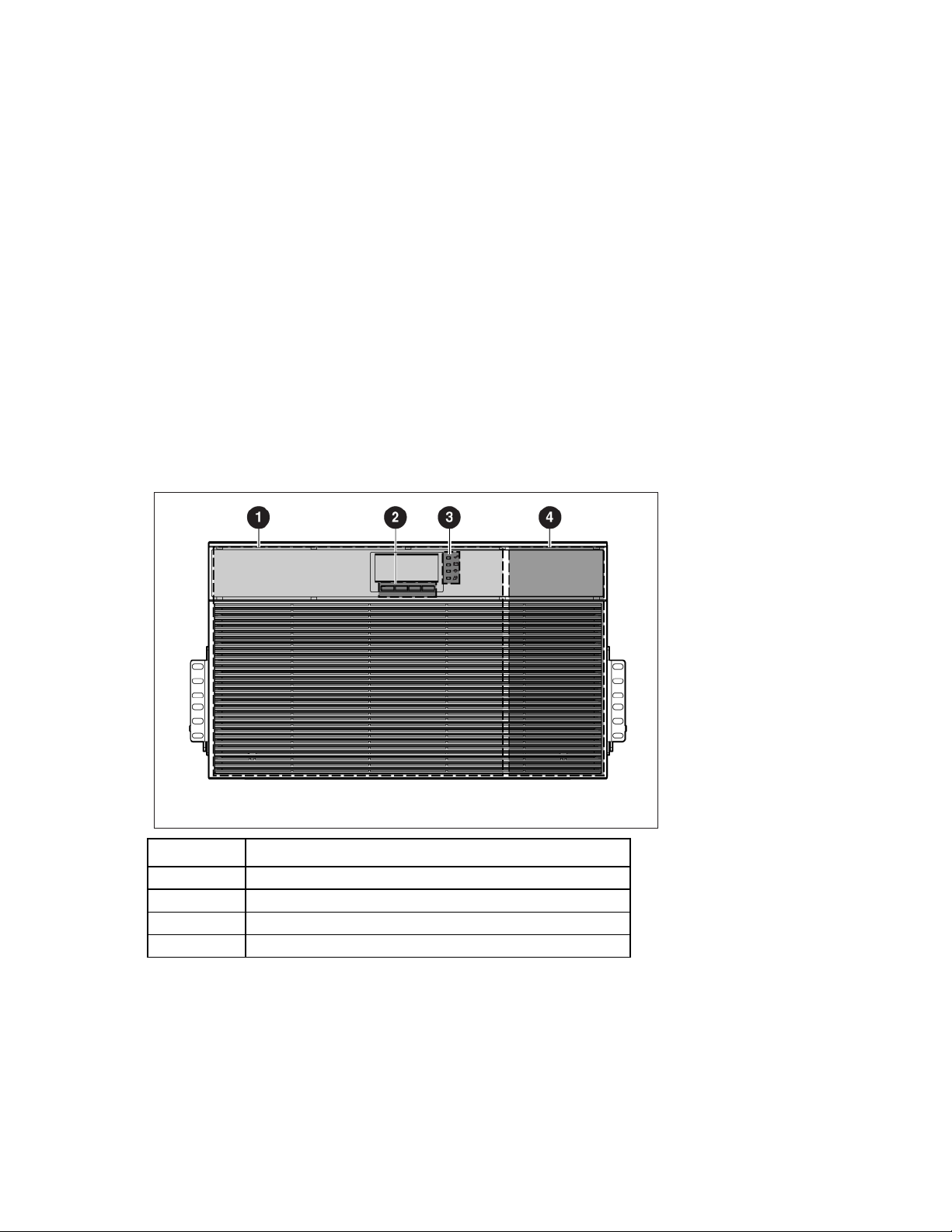
UPS front panel
Item Description
1
2
3
4
Battery compartment
Control buttons
Electronics compartment
Component identification 8
Page 9
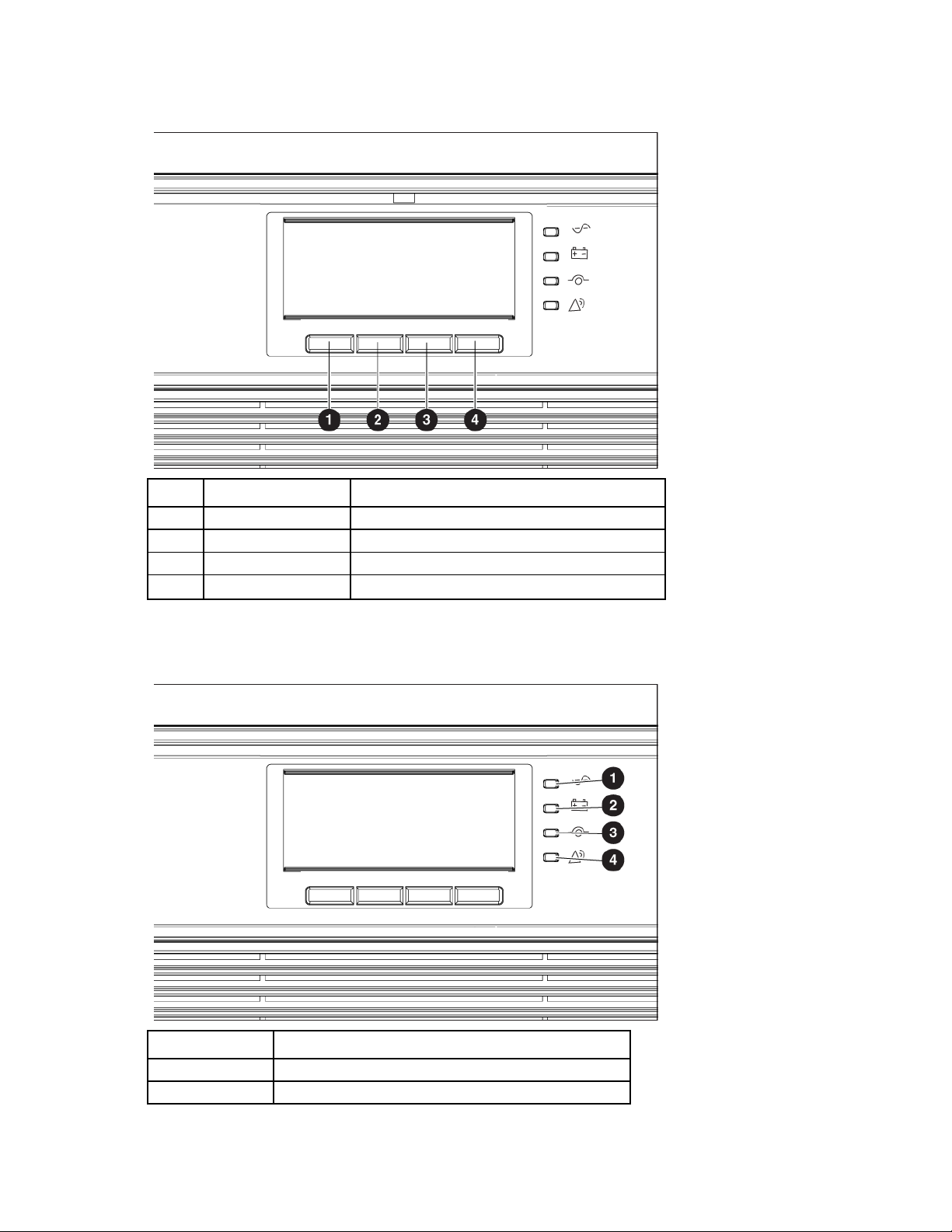
UPS front panel controls
Item Description Function
1
2
3
4
Left arrow or ESC Cancel/return to the previous menu
Up arrow Scroll through the menu structure
Down arrow Scroll through the menu structure
Right arrow or enter Select an option
UPS front panel LED indicators
Item LED description
1
2
Power On
On Battery
Component identification 9
Page 10
Item LED description
Input/output power connectors
Output connector (only for use with output module)
3
4
Auto-bypass
Alarm
For more information, see "LED and audible alarm troubleshooting (on page 94)" .
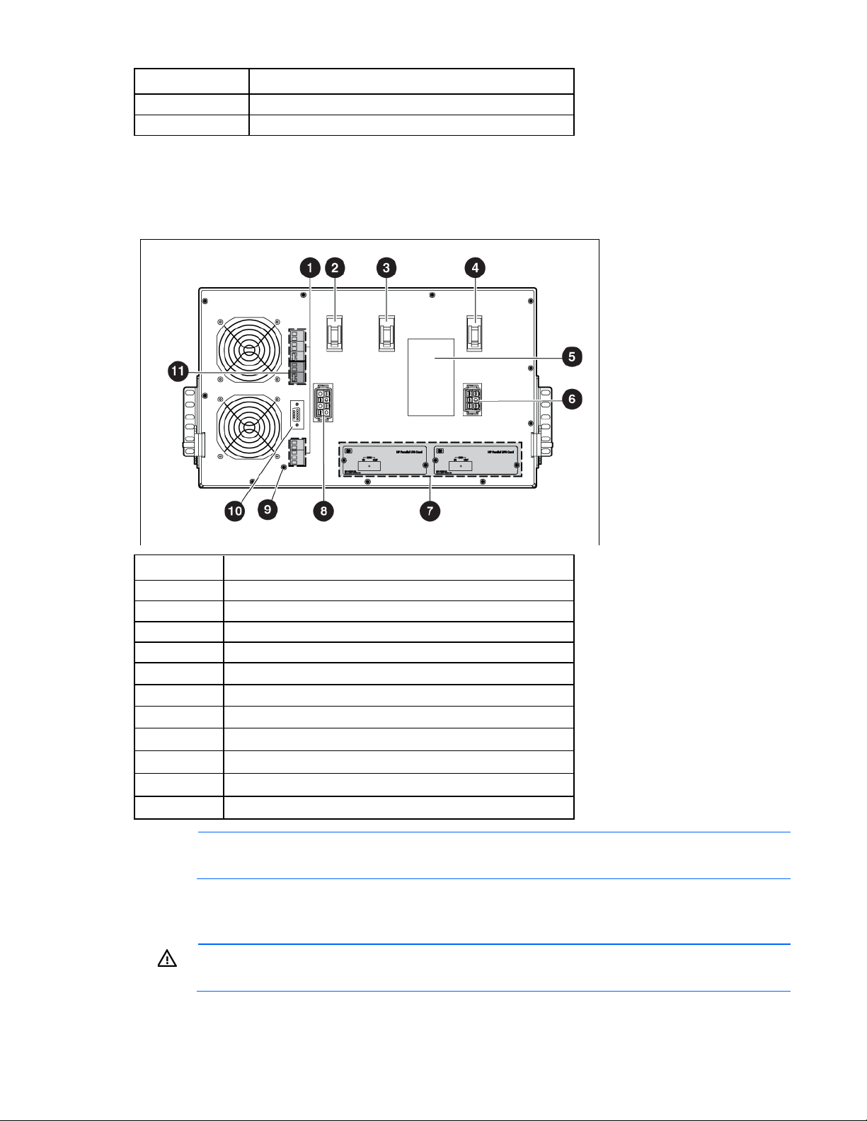
UPS rear panel
Item Description
1
2
3
4
5
6
7
8
9
10
11
NOTE: For proper UPS operation, be sure that the terminal block jumpers are inserted as shown.
Communications terminal block
Output circuit breaker
Input circuit breaker
Battery circuit breaker
ERM connector
Option card slots
Ground bonding screw
DB-9 service port
REPO port (NO and NC)
REPO port
WARNING: The REPO circuit is an IEC 60950 safety extra low voltage (SELV) circuit. This circuit
must be separated from any hazardous voltage circuits by reinforced insulation.
Component identification 10
Page 11

CAUTION:
48 S1, “Electrical Installation of the Buildings, Part 4: Protection for Safety, Chapter 46:
• Do not connect the REPO port to any utility connected circuits. Reinforced insulation to the
utility is required. The REPO switch must have a minimum rating of 24 Vdc and 20 mA and be
a dedicated latching-type switch for the 3 Phase UPS only, no other device or circuit including
a single phase UPS. The REPO signal must remain active for at least 250 ms for proper
operation.
• To ensure that the UPS stops supplying power to the load during any mode of operation, the
input power must be disconnected from the UPS when the EPO function is activated.
NOTE: For Europe, the emergency switch requirements are detailed in Harmonized document
HD-384Isolation and Switching.”
The UPS includes an isolated REPO port. When properly wired, the REPO feature allows the power at the
UPS output receptacles to be switched off from a remote location. When REPO is activated, the UPS powers
down all converters, de-energizes all system relays, trips the UPS battery circuit breaker, and powers down
within 10 to 15 seconds. However, the unit continues to have logic power (the display is still active) and is
not fully powered down until input power is disconnected from the unit. This feature can be used for powering
down the load and the UPS by thermal relay, for example in the event of room overtemperature.
To use this feature, the REPO port must be connected to a remote switch (not supplied). The REPO switch is
used in conjunction with a main disconnect device that removes the AC source from the input of the UPS.
When the switch is activated:
• The REPO feature immediately powers down protected devices and does not utilize the orderly
shutdown procedure initiated by power management software.
• The REPO feature shuts down UPS units operating under either utility or battery power.
Keep the REPO connector installed in the REPO port on the UPS even if the REPO function is not needed. The
REPO connection are listed below:
Wire function Terminal wire size rating Suggested wire size
L1
L2
There are two REPO positions, normally-open (NO) or normally-closed (NC). The pins on the NC REPO
connector are connected together. When this connection is open, the logic circuitry completely shuts down
the UPS, thus preventing the power from supplying the load. To use NC REPO, remove the jumper wire and
connect an NC external switch. To use NO REPO, connect an NO external switch. For REPO locations, see
Connecting REPO port
.
NOTE: If the UPS was operating on battery power when the remote switch was closed, no power
is available to the load devices until utility power is restored and the UPS has been manually
powered up.
To restore power to the load devices after the REPO feature is activated, press the Power On button after the
AC source is reconnected to the UPS.
IMPORTANT: Pressing and holding the Power On button without utility present normally initiates
a battery start and the UPS assumes the load. However, if the Power On button is pressed and a
REPO is detected, battery start is inhibited and the UPS is not able to assume the load. The
electronics module fan spins and the Alarm LED and an audible alarm are active as long as the
Power On button is held.
4–0.32 mm2 (12–22 AWG) 0.82 mm2 (18 AWG)
4–0.32 mm2 (12–22 AWG) 0.82 mm2 (18 AWG)
Component identification 11
Page 12
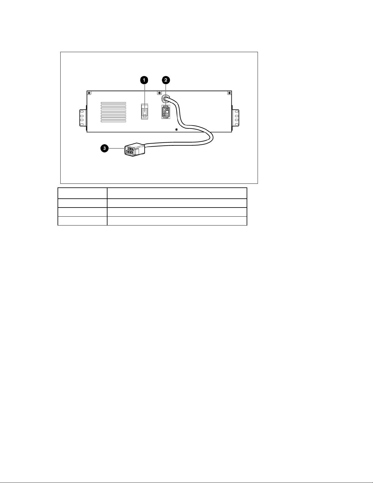
ERM rear panel
Item Description
1
2
3
Circuit breaker
ERM input connector (from another ERM output)
ERM output connector (to the UPS or another ERM)
Component identification 12
Page 13
UPS installation
A risk of personal injury from electric shock and hazardous energy levels exists. The
Precautions
Save these instructions. This document contains important safety instructions that should be followed during
installation, operation, and maintenance of the UPS and batteries.
WARNING:
installation of options and routine maintenance and service of this product must be performed by
individuals who are knowledgeable about the procedures, precautions, and hazards associated
with AC power products.
This symbol indicates that the UPS exceeds the recommended weight for one individual
140 kg
307 lb
to handle safely.
WARNING: To reduce the risk of personal injury or damage to the equipment, observe
local occupational health and safety requirements and guidelines for manual material
handling.
This symbol indicates that the ERM exceeds the recommended weight for one individual
77 kg
170 lb
to handle safely.
WARNING: To reduce the risk of personal injury or damage to the equipment, observe
local occupational health and safety requirements and guidelines for manual material
handling.
WARNING: To prevent personal injury from earth conductor leakage current:
• Do not operate the UPS while disconnected from the utility power source.
• Disconnect load devices before disconnecting the UPS from the utility power source.
Preparing to install the hardware
Before installing the hardware:
1. Be sure the necessary tools and materials (on page 13) are available.
2. Select an installation site ("Selecting a site" on page 14).
Tools and materials
3. Prepare the equipment ("Readying the equipment" on page 14) for installation in the rack.
The following tools are required for installation:
• Phillips screwdriver
• 10-mm hex-nut wrench
• T-25 Torx driver
A cage nut-fitting tool is supplied with the rack.
UPS installation 13
Page 14

Selecting a site
WARNING: To prevent fire or electric shock, install the unit in a temperature- and
When selecting a site, consider the following factors:
• Elevated operating ambient temperature—If the equipment is installed in a closed or multi-unit rack
• Reduced air flow—In the rack, the rate of air flow required for safe operation of the equipment must not
• Circuit overloading—Consideration should be given to the connection of the equipment to the supply
• Reliable earthing—Reliable earthing of rack-mounted equipment should be maintained. Particular
• Electrical requirements—All models require a dedicated (unshared) branch circuit, suitably rated for the
humidity-controlled indoor environment, free of conductive contaminants.
assembly, the operating ambient temperature of the rack environment might be greater than room
ambient temperature. Install the equipment in an environment compatible with the operating
temperature ("Environmental specifications" on page 103).
be compromised.
circuit and the effect that overloading of the circuits might have on overcurrent protection and supply
wiring. Appropriate consideration of equipment nameplate ratings should be used when addressing
this concern.
attention should be given to supply connections other than direct connections to the branch circuit, such
as the use of power strips.
specific UPS as stated in "Input specifications" .
Readying the equipment
1. Check the battery recharge date specified on the label that is affixed to the shipping carton.
IMPORTANT: Do not use the battery if the recharge date has passed. If the date on the battery
recharge date label has passed without the battery being recharged, contact an HP authorized
2. Transport the packaged unit to its installation location.
3. Unpack the equipment near the rack where the unit will be assembled.
service representative for directions.
Installing the mounting rails
WARNING: To reduce the risk of personal injury or damage to the equipment, be sure that:
• The leveling feet are extended to the floor.
• The full weight of the rack rests on the leveling feet.
• The stabilizing feet are attached to the rack if it is a single-rack installation.
• The racks are coupled together in multiple-rack installations.
• Only one component is extended at a time. A rack may become unstable if more than one
component is extended for any reason.
WARNING: A risk of personal injury or damage to the equipment exists. Uneven loading of
equipment in the rack might cause the rack to become unstable. Install the heavier components
first, and then continue to populate the rack from the bottom to the top.
UPS installation 14
Page 15
CAUTION: Always plan the rack installation so that the heaviest item is on the bottom of the rack.
Install the heaviest item first, and continue to populate the rack from the bottom to the top.
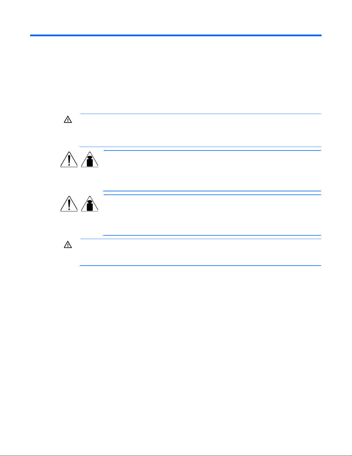
NOTE: Mounting hardware for square- and round-holed racks is included in the UPS kit.
1. Select the proper holes in the rack for positioning the UPS in the rack.
The UPS rails are installed in positions 1 and 12.
2. Loosen the hex nuts, and extend the brackets to the desired length.
UPS installation 15
Page 16
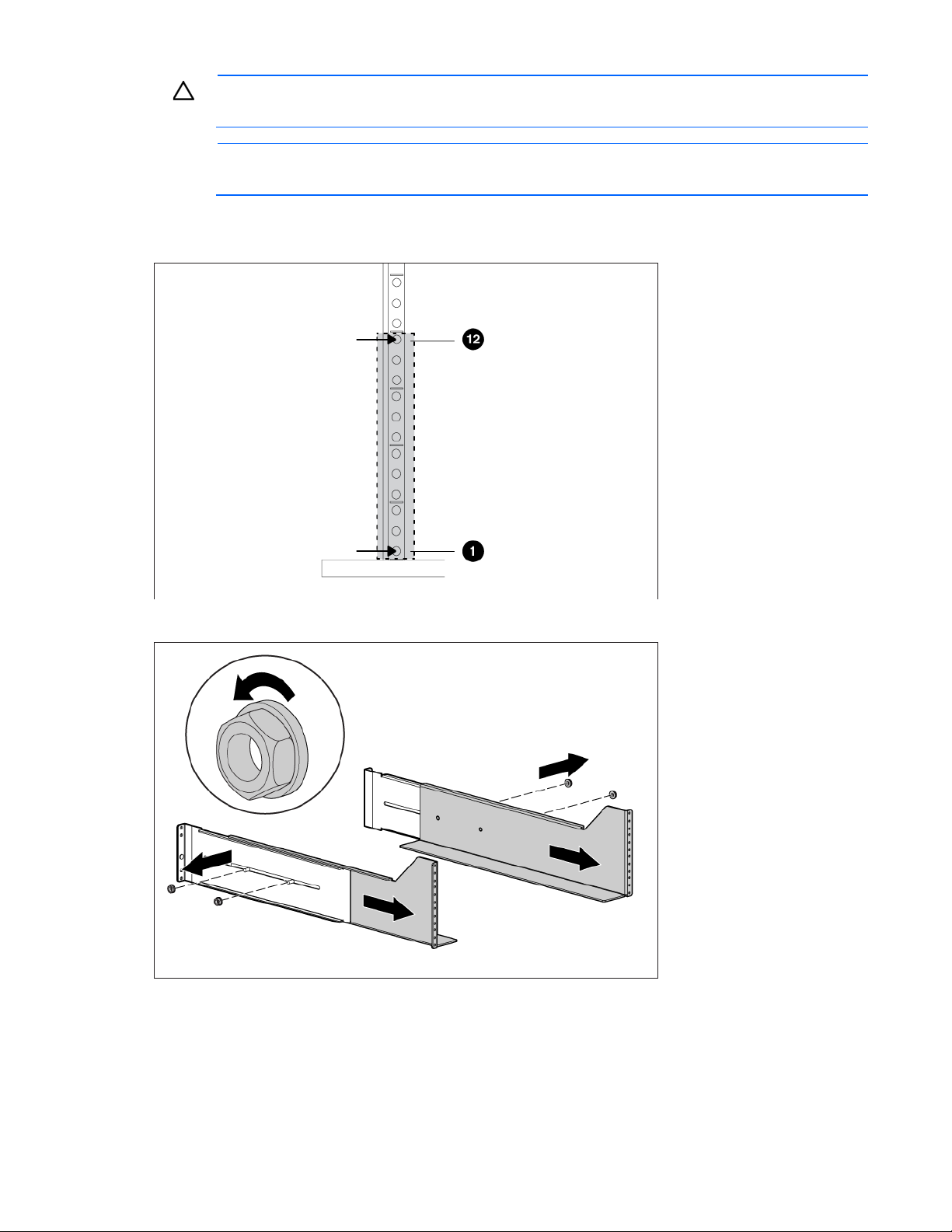
3.
Insert screws through the rack into the mounting rail and the front of each mounting bracket.
4. Install cage nuts or clip nuts into the rear of the rack.
UPS installation 16
Page 17
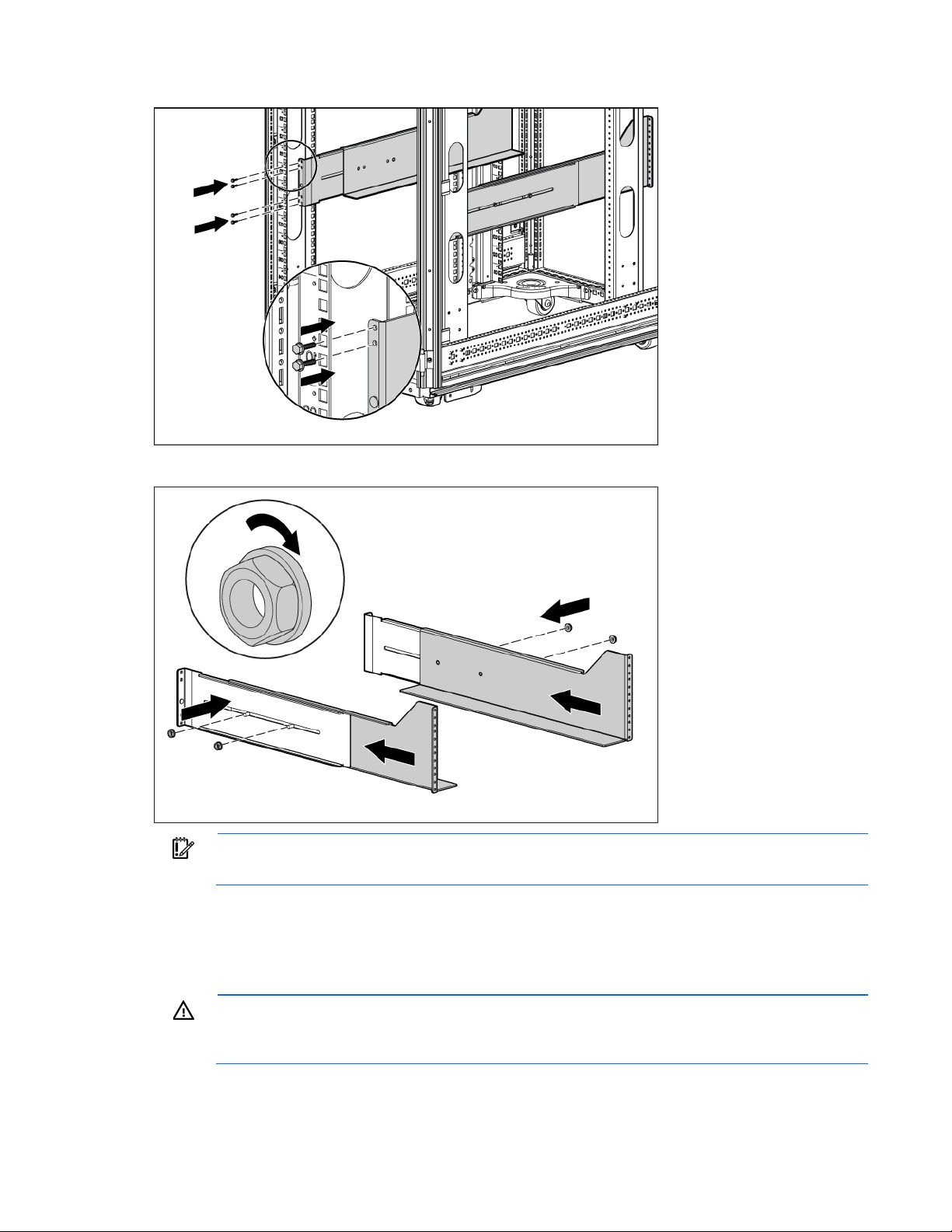
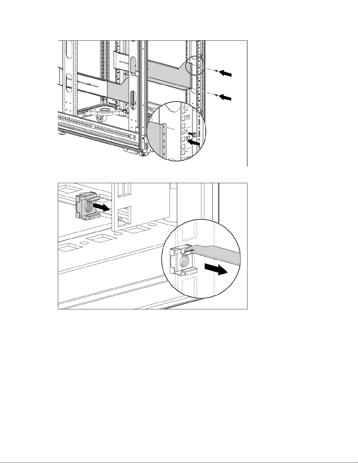
5.
Insert screws through the mounting rail into the cage nuts or clip nuts.
6. Tighten the hex nuts.
IMPORTANT: If preparing the rails for integrated shipping, install the rear mounting brackets.
Installing the UPS
Before installing the UPS, review and observe all warnings in "Precautions (on page 13)."
WARNING: A risk of personal injury or damage to the equipment exists. Uneven loading of
equipment in the rack might cause the rack to become unstable. Install the heavier components
first, and then continue to populate the rack from the bottom to the top.
UPS installation 17
Page 18
CAUTION: Always plan the rack installation so that the heaviest item is on the bottom of the rack.
Install the heaviest item first, and continue to populate the rack from the bottom to the top.
1. Install the mounting rails ("Installing the mounting rails" on page 56, "Installing the mounting rails" on
page 14).
2. With one person on each side of the carton, lift the chassis and lower it to the floor in front of the rack.
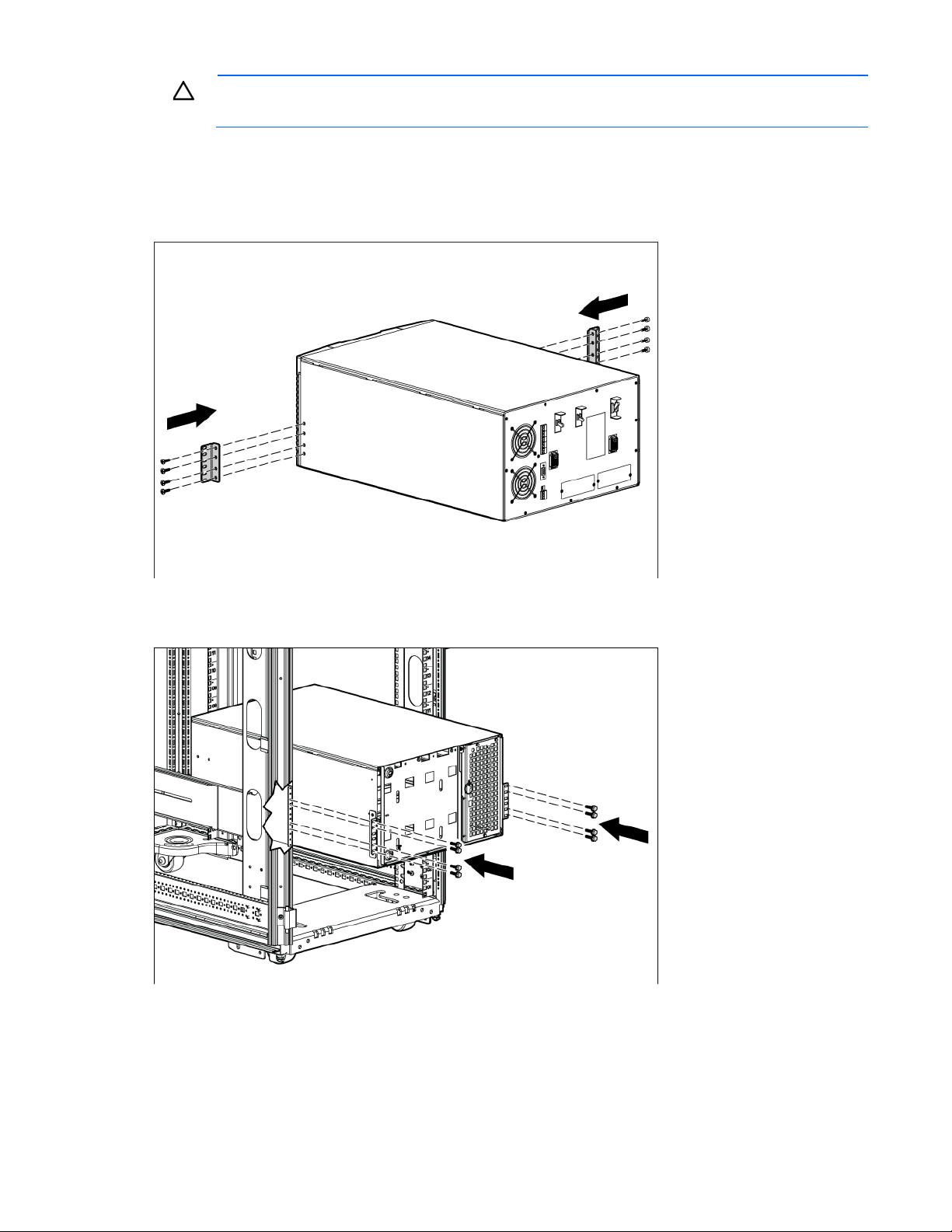
3. Install the mounting ears on the chassis using the screws provided.
4. With one person on each side, lift the chassis to rail level and slide the chassis on the mounting rails.
5. Attach the chassis to the rack using the supplied screws.
6. If using the rear mounting brackets, be sure that the bracket tabs are fully inserted into the rear panel
cutouts, then tighten the brackets.
UPS installation 18
Page 19
Removing the UPS battery bracket
Be sure that all circuit breakers on the rear panel of the UPS are in the Off position.
Installing the batteries
WARNING: To prevent personal injury, prepare the area and observe all materials-handling
procedures when transporting a battery module. Battery modules weigh 20 kg (44 lb).
UPS installation 19
Page 20
Replacing the UPS battery bracket
Attaching the UPS front bezel
1. Connect the cable to the electronics module.
2. Attach the UPS front bezel.
Connecting the ground bonding cable
The ground bonding screw is provided as an attachment point for conductors. Use a ground bonding cable
if the rack contains any conductors for the purpose of functional grounding or bonding of ungrounded metal
parts.
UPS installation 20
Page 21
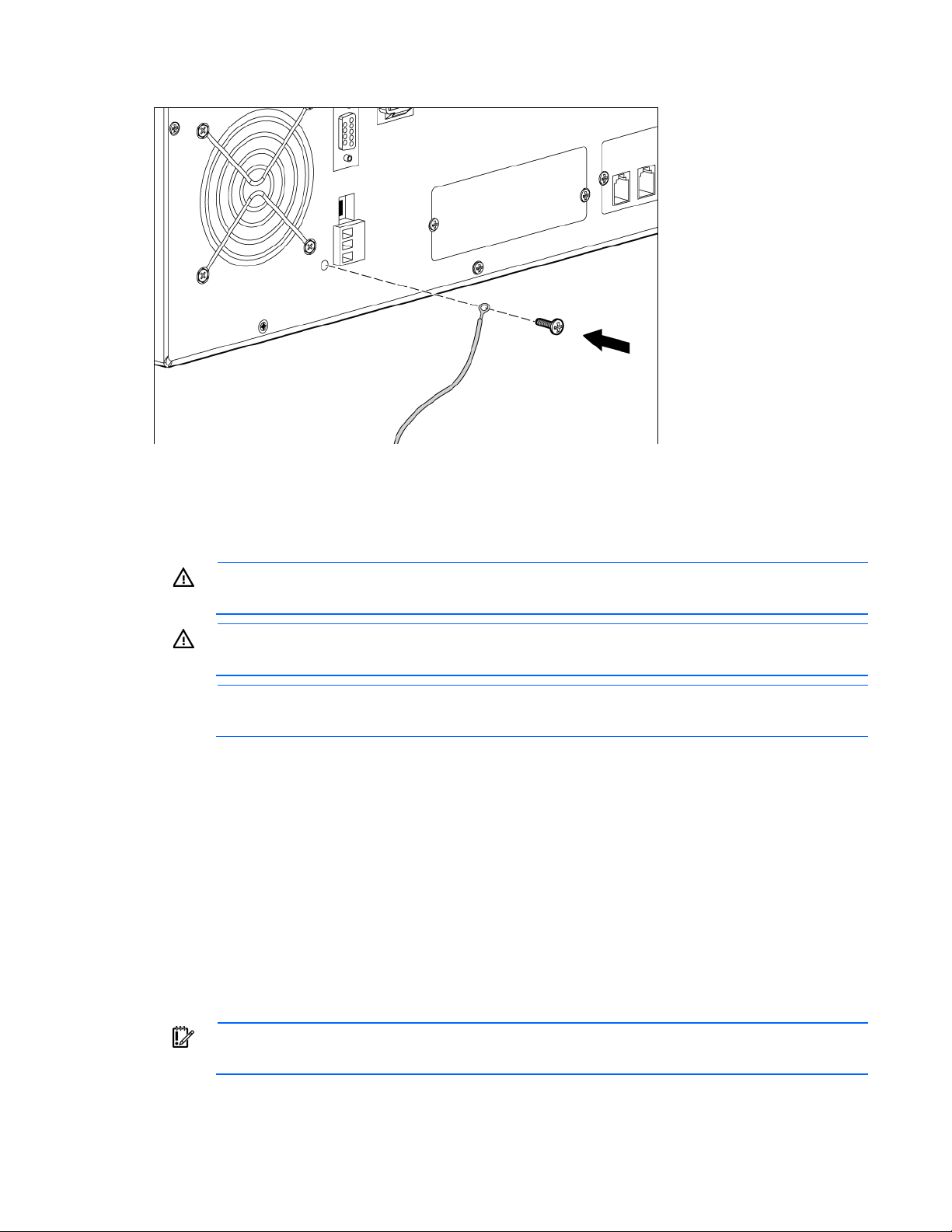
The ground bonding cable is not included.
Connecting the REPO port
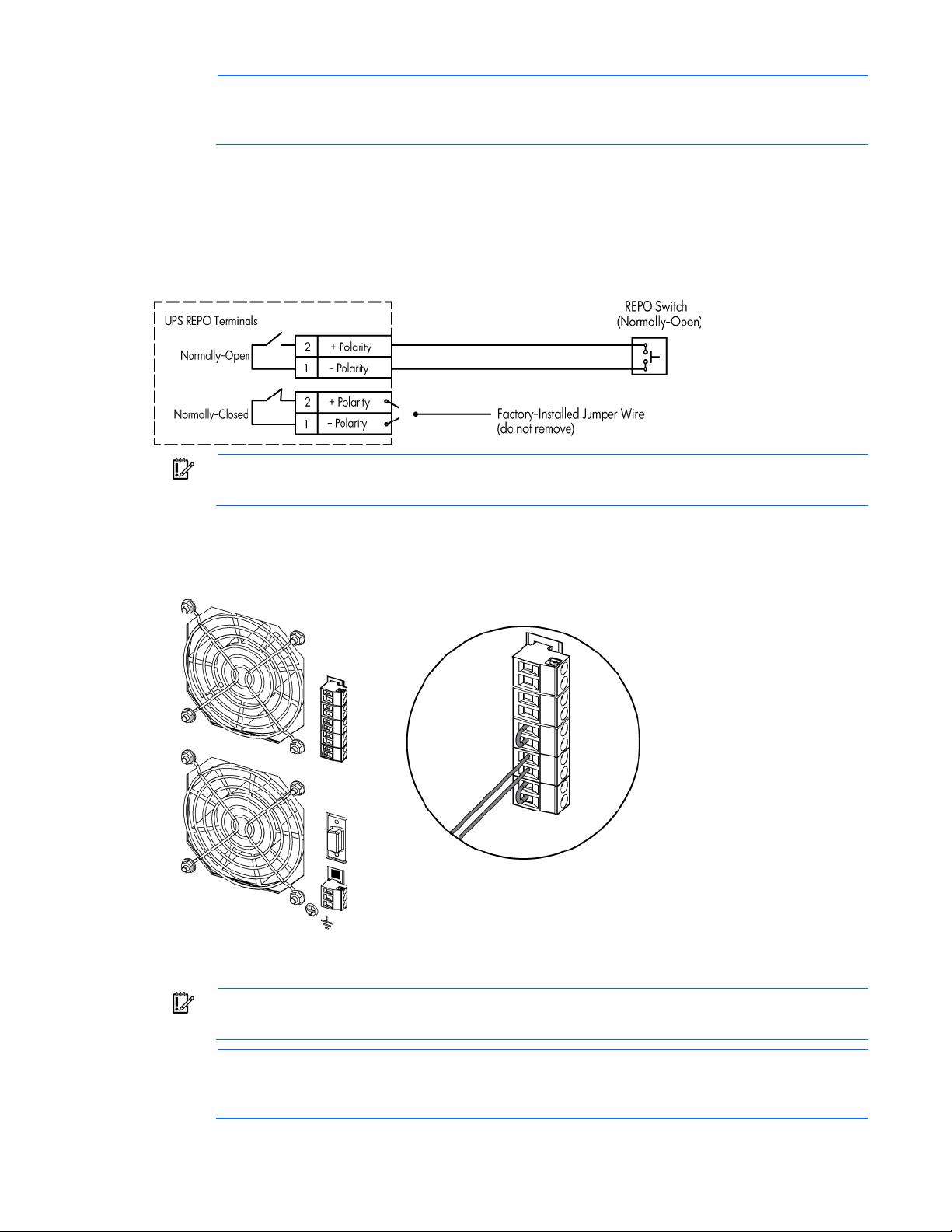
This UPS has two REPO ports, normally-open and normally-closed. Before connecting to a REPO port, review
and observe all warnings.
WARNING: The pins on the REPO port are polarity sensitive. Be sure to verify polarity while
HP recommends using different colors for the positive and negative wires.
To avoid inadvertant EPO:
• Minimize wire strain while connecting the REPO port.
• Avoid allowing the wires to hang in the rear of the UPS.
• Use tie wraps and tie wrap blocks to secure the wires tightly to the rack and the rear of the UPS.
connecting the REPO port in parallel with other HP UPSs.
WARNING: To meet the requirements stated in NEC (NFPA 70) Articles 645-10 and 645-11, a
UPS installed in a computer equipment room must be connected to a REPO circuit.
NOTE: Wire the connector block using stranded, nonshielded wire (AWG #22 - #18, or
equivalent).
For more information about the REPO port, see "REPO port (on page 10)" .
For information about verifying the REPO connection, see "Verifying the REPO port connection (on page 71)"
Connecting to a normally-open contact
.
IMPORTANT: The remote switch must be in the open position to enable power to the UPS output.
UPS installation 21
Page 22
NOTE: The REPO wiring of a standalone UPS can be connected with the REPO wiring of a
parallel system if the same sense (NO or NC) contacts are used. Be sure to match the polarity for
parallel system if the same sense (NO or NC) contacts are used. Be sure to match the polarity for
the contacts.
1. Verify that the UPS is powered down and all power sources are removed. For more information, see
"Powering down the standalone UPS (on page 72)."
2. Mount the remote REPO switch. HP recommends mounting the REPO switch near the operator's
consoles or near the exit doors. For enclosure dimensions and wiring knockouts, see the REPO switch
manufacturer's installation instructions.
3. Connect the appropriate external switch to terminal block 4, normally-open REPO.
IMPORTANT: Always test the REPO function before applying the critical load to avoid accidental
load loss. For more information, see "Verifying the REPO port connection (on page 71)."
4. Reconnect terminal block 4, normally-open REPO, and then power on the UPS manually to restart. Pins
should remain open to keep the UPS running. Maximum resistance is 10 ohm.
5. Verify that the jumper is inserted in terminal block 5.
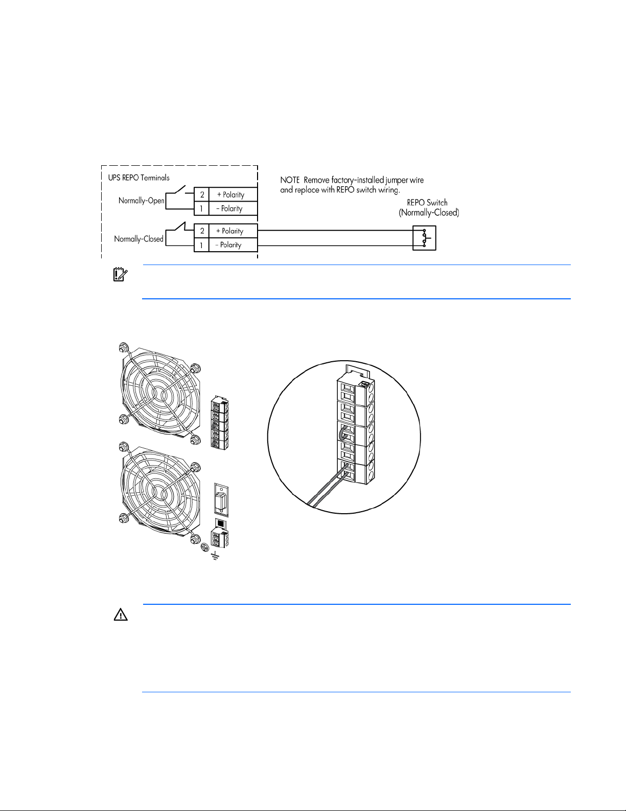
Connecting to a normally-closed contact
IMPORTANT: The remote switch must be in the closed position to enable power to the UPS
output.
NOTE: The REPO wiring of a standalone UPS can be connected with the REPO wiring of a
the contacts.
UPS installation 22
Page 23
1. Verify that the UPS is powered down and all power sources are removed. For more information, see
"Powering down the standalone UPS (on page 72)."
2. Mount the remote REPO switch. HP recommends mounting the REPO switch near the operator's
consoles or near the exit doors. For enclosure dimensions and wiring knockouts, see the REPO switch
manufacturer's installation instructions.
3. Connect the appropriate external switch to terminal block 5, normally-closed REPO, and then discard
the jumper wire.
IMPORTANT: Always test the REPO function before applying the critical load to avoid accidental
load loss. For more information, see "Verifying the REPO port connection (on page 71)."
4. Reconnect terminal block 5, normally-closed REPO, and then power on the UPS manually to restart. The
pins must be shorted to keep the UPS running. Maximum resistance is 10 ohm.
Connecting the UPS to utility power
WARNING: To prevent injury from electric shock or damage to the equipment:
• Plug the input line cord into a grounded (earthed) electrical outlet that is installed near the
equipment and is easily accessible.
• Do not disable the grounding plug on the input line cord. The grounding plug is an important
safety feature.
Connect the UPS to a grounded utility power outlet.
• Do not use extension cords.
UPS installation 23
Page 24
Switching on the UPS battery circuit breaker
When the UPS is plugged in and the battery circuit breaker is on, the UPS automatically enters Standby mode
and begins charging the batteries.
Connecting devices to the UPS
CAUTION: Do not plug laser printers into the UPS output receptacles. The instantaneous current
Before connecting devices, verify that the UPS will not overload by checking that the ratings of the devices do
not exceed the UPS capacity. If the equipment rating is listed in amps, multiply the number of amps by the
nominal AC source to determine the VA.
To provide additional receptacles:
• For the 8kVA models—Plug a PDU into the UPS output receptacle at the end of the power cord.
• For the 12kVA models—
drawn by this type of printer can overload the UPS.
a. Install the included output module on the rear rack frame.
UPS installation 24
Page 25
b.
Plug the output module into the special UPS output receptacle, located on the rear of the UPS.
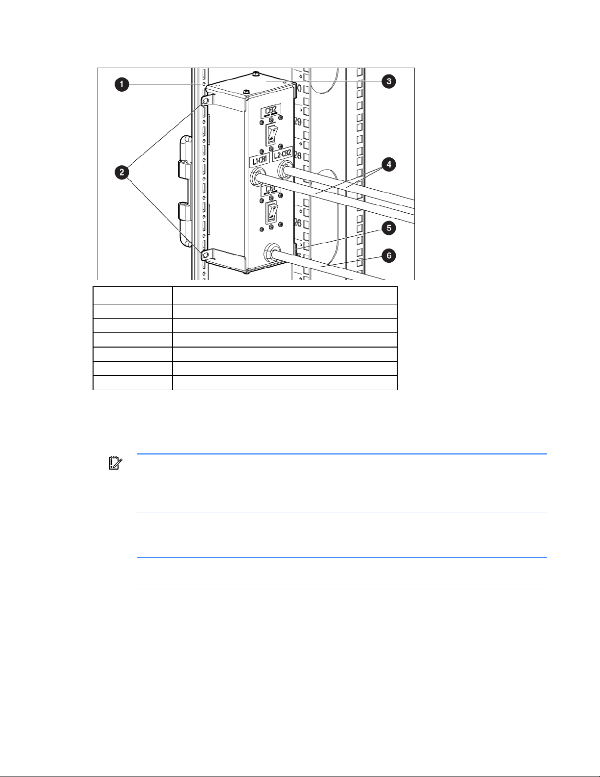
Item Description
1
2
3
4
5
6
Rack corner post
Mounting locations
Mounting top bracket
Output cord
Mounting bottom bracket
Input cord
Charging the UPS batteries
With the UPS in Standby mode, allow the batteries to charge before putting the UPS into service.
IMPORTANT: Charge the batteries for at least 48 hours before supplying backup power to
devices. The batteries charge to:
• 80 percent of their capacity within 5 hours
• 100 percent of their capacity within 48 hours
Powering up the standalone UPS
NOTE: Be sure that the total equipment ratings do not exceed the UPS capacity to prevent an
1. Switch the UPS input circuit breaker to the On position.
overload alarm.
2. Wait for the UPS front panel display to illuminate.
The Alarm LED flashes.
3. Check the UPS front panel display for active alarms or notices (other than "Batteries Disconnected").
Resolve any active alarms before continuing. For more information, see "Troubleshooting (on page
94)" .
4. Switch the UPS battery circuit breaker to the On position.
UPS installation 25
Page 26

5.
If optional ERMs are installed, switch all ERM battery circuit breakers to the On position.
Be sure that the "Batteries Disconnected" alarm has cleared. Be sure that no other alarms appear on the
UPS front panel display. If the Alarm LED is flashing, do not proceed until all alarms clear. Check the
UPS status from the front panel to view the active alarms. Correct the alarms and restart if necessary.
6. Press any button once and then press the left arrow button to select the TURN UPS ON/OFF menu.
7. Press the down arrow button to select the TURN UPS ON option. Press the left arrow button.
8. Confirm the selection. Press and hold the left arrow button for three seconds, until the UPS stops
beeping.
The UPS front panel display indicates "UPS starting..." while relays click and the fans start. The display
returns to the status menu.
Be sure that the Power On LED illuminates.
If the Alarm LED is flashing, do not proceed until all alarms are clear. Check the UPS status from the front
panel to view the active alarms. Correct the alarms and restart if necessary. The UPS should be in
Operate mode.
9. Switch the output circuit breaker to the On position.
10. To return to the default logo screen, press the ESC button.
Installing in a parallel configuration
WARNING: This equipment must be installed by a licensed electrician or trained service
A UPS connected to a Bus Bar with a paralleling line cord is identified as a member of the parallel system.
The Bus Bar connects the line and load to a common power bus. A parallel system can be configured for
capacity or redundancy.
The UPS models in a parallel configuration require a dedicated branch circuit that meets the following
requirements:
• Circuit with overcurrent protection, depending on parallel configuration:
Number of UPSs in parallel
system
3
4
5
6 (N+1 system)
• Three-phase, 4-wire plus ground, 208 Y/120 V nominal (NA) or 400 Y/230 V nominal, 380-415 VAC
personnel familiar with high-power circuitry
HP 3 Phase NA HP 3 Phase INTL
150 A 75 A
200 A 100 A
225 A 125 A
225 A 160 A
acceptable (INTL)
• 50/60 Hz
• The breaker must be wall-mounted and be readily accessible to the operator
• Flexible or rigid metal conduit
Installing the input and output wiring
Be sure that the UPSs are properly installed in individual rail kits in a rack containing a Bus Bar.
UPS installation 26
Page 27
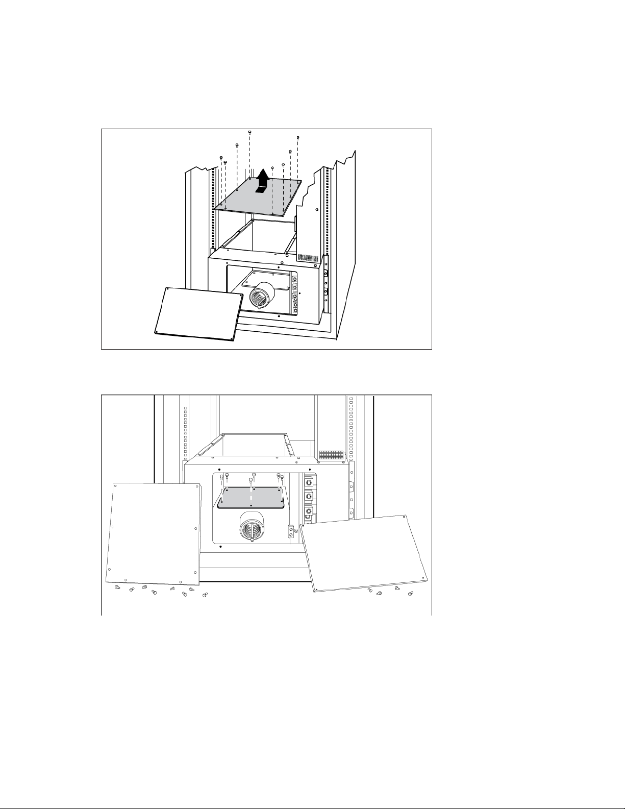
Bottom entry
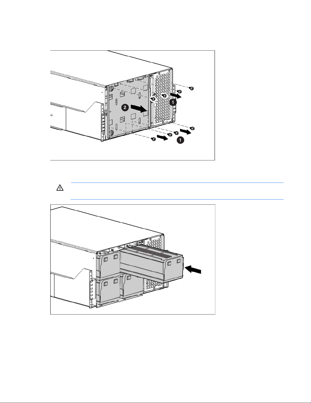
1. Remove the UPS above the wireway. See "Replacing the UPS (on page 89)" .
2. Remove the eight screws on the wireway top cover and retain.
3. Slide the cover back and off the wireway and retain.
4. Remove the six screws on the conduit landing plate and retain.
5. Remove the plate and retain.
6. Use a Greenlee punch to provide one or more holes in the conduit landing plate to accommodate the
input and output wiring from the utility to the Power Bus Bar.
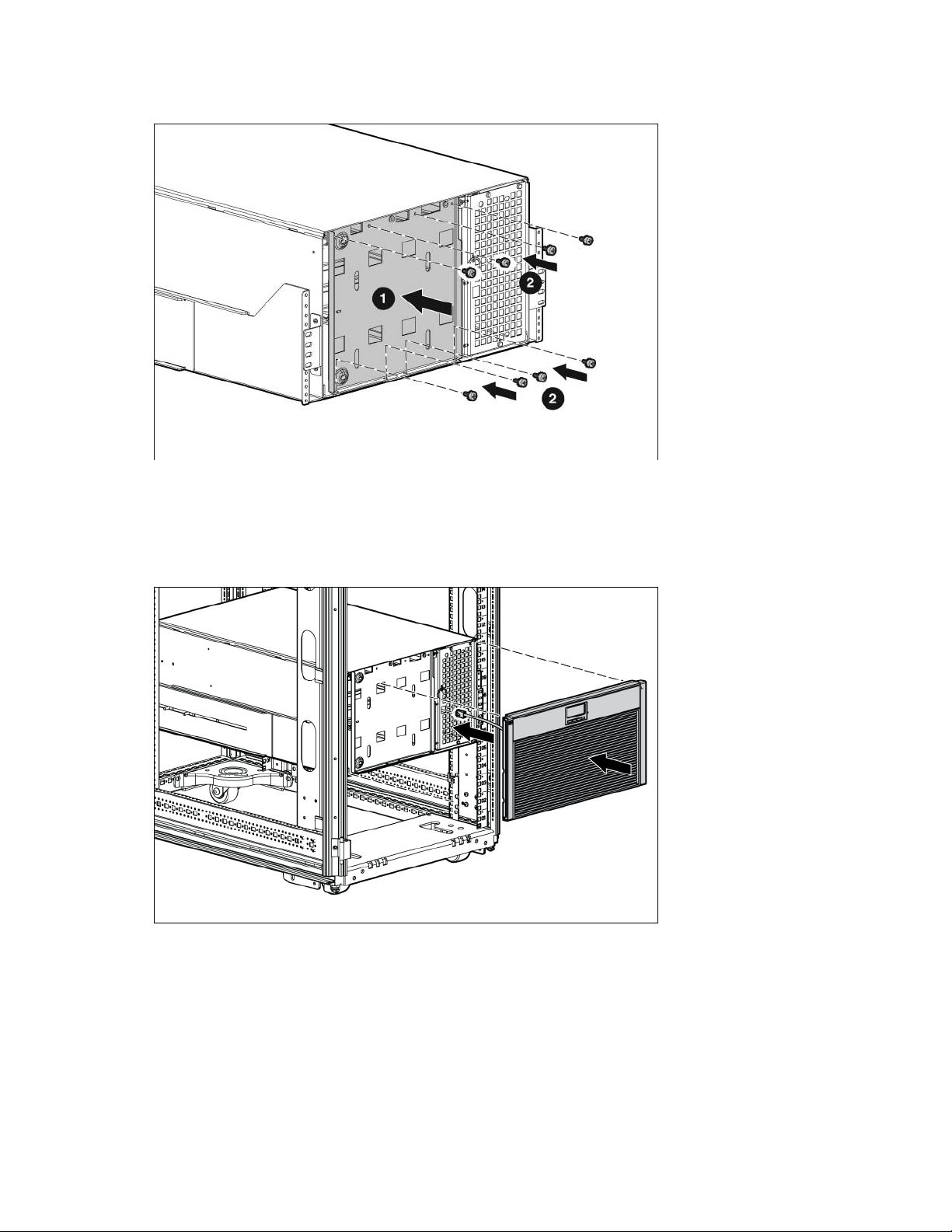
7. Replace the conduit landing plate.
8. Reinstall the UPS above the wireway.
UPS installation 27
Page 28
Top entry
Top entry wiring does not interfere with access areas for the fans, connectors, breakers
Use a Greenlee punch to provide one or more holes in the top of the wireway. Install one or more holes in
the center rear of the top of the racks.
NOTE:
or X-Slot cards on any HP 3 Phase UPS. See the wireway label.
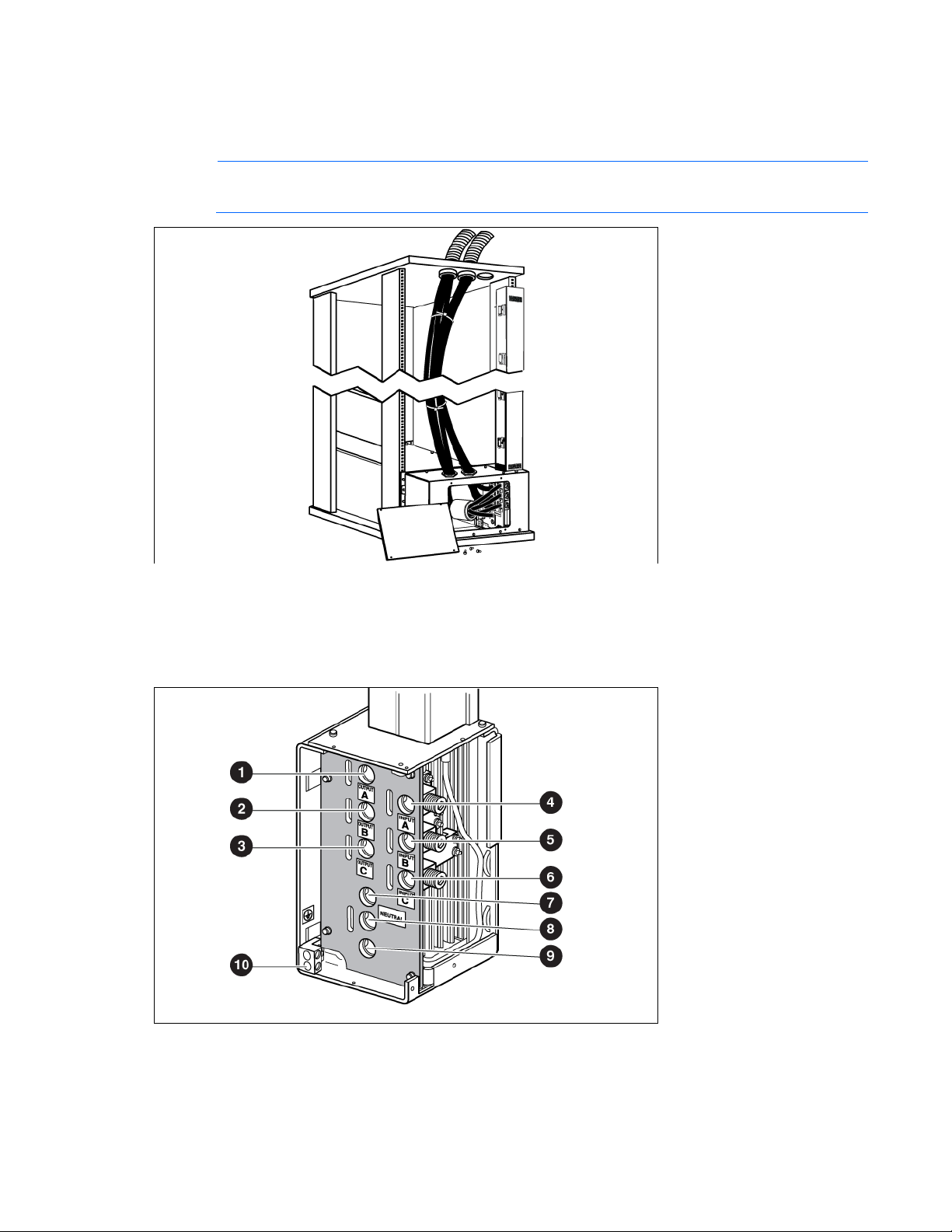
Wiring the terminal block
Connect the input, output and ground wires to the Power Bus Bar terminal block. Route the three input phases
and the input neutral through the ferrite assembly.
Wire gauge depends on overcurrent protection rating required. For more information, see "Installing in a
parallel configuration (on page 26)." Reference the NEC, NFPA 70, for wire sizing.
UPS installation 28
Page 29

Power Bus Bar
terminal block
Output
Terminal
position
Power Bus Bar wire
function
Terminal wire size
rating*
1 Phase 1 out 13.3 mm
to 177 mm
2
(6 AWG)
2
(350
Tightening torque
31.1 Nm (275 lb in)
kcmil)
2 Phase 2 out 13.3 mm2 (6 AWG)
2
to 177 mm
(350
31.1 Nm (275 lb in)
kcmil)
3 Phase 3 out 13.3 mm2 (6 AWG)
to 177 mm
2
(350
31.1 Nm (275 lb in)
kcmil)
Input
4 Phase 1 in 13.3 mm
to 177 mm
2
(6 AWG)
2
(350
31.1 Nm (275 lb in)
kcmil)
5 Phase 2 in 13.3 mm2 (6 AWG)
to 177 mm
2
(350
31.1 Nm (275 lb in)
kcmil)
6 Phase 3 in 13.3 mm2 (6 AWG)
to 177 mm
2
(350
31.1 Nm (275 lb in)
kcmil)
2
Neutral
7 Neutral 13.3 mm
to 177 mm
(6 AWG)
2
(350
31.1 Nm (275 lb in)
kcmil)
8 Neutral 13.3 mm2 (6 AWG)
to 177 mm
2
(350
31.1 Nm (275 lb in)
kcmil)
9 Neutral 13.3 mm2 (6 AWG)
2
to 177 mm
(350
31.1 Nm (275 lb in)
kcmil)
2
Safety ground
*Use 13.3 mm2 (6 AWG) 90º C copper wire minimum.
10 Ground 18 mm
215mm
(4 AWG) to
2
(400 kcmil)
1.8 (16 lb in)
Connecting the ground bonding cable
The ground bonding screw is provided as an attachment point for conductors. Use a ground bonding cable
if the rack contains any conductors for the purpose of functional grounding or bonding of ungrounded metal
parts.
UPS installation 29
Page 30

The ground bonding cable is not included.
Connecting the REPO port
This UPS has two REPO ports, normally-open and normally-closed. Before connecting to a REPO port, review
and observe all warnings.
WARNING: The pins on the REPO port are polarity sensitive. Be sure to verify polarity while
HP recommends using different colors for the positive and negative wires.
To avoid inadvertant EPO:
• Minimize wire strain while connecting the REPO port.
• Avoid allowing the wires to hang in the rear of the UPS.
• Use tie wraps and tie wrap blocks to secure the wires tightly to the rack and the rear of the UPS.
connecting the REPO port in parallel with other HP UPSs.
WARNING: To meet the requirements stated in NEC (NFPA 70) Articles 645-10 and 645-11, a
UPS installed in a computer equipment room must be connected to a REPO circuit.
NOTE: Wire the connector block using stranded, nonshielded wire (AWG #22 - #18, or
equivalent).
For more information about the REPO port, see "REPO port (on page 10)" .
For information about verifying the REPO connection, see "Verifying the REPO port connection (on page 71)"
Connecting to a normally-open contact
.
IMPORTANT: The remote switch must be in the open position to enable power to the UPS output.
UPS installation 30
Page 31

You can install an optional REPO circuit that shuts down the entire parallel system using a single switch. To
install a REPO switch for a parallel system, the selected REPO command (NO or NC) contacts from each UPS
in the system must be in parallel.
To install a REPO switch for a parallel system:
1. Verify that the UPS system is powered down and all power sources are removed. For more information,
see "Powering down the parallel system (on page 73)."
2. Mount the remote REPO switch. HP recommends mounting the REPO switch near the operator's
consoles or near the exit doors. For enclosure dimensions and wiring knockouts, see the REPO switch
manufacturer's installation instructions.
UPS installation 31
Page 32

3.
Connect the appropriate external switch to terminal block 4, normally-open REPO. Connect Pin 1 to Pin
1 and connect Pin 2 to Pin 2 of each UPS.
IMPORTANT: Always test the REPO function before applying the critical load to avoid accidental
load loss. For more information, see "Verifying the REPO port connection (on page 71)."
UPS installation 32
Page 33

4.
Reconnect terminal block 4, normally-open REPO, and then power on the UPS manually to restart. The
pins should remain open to keep the UPS running.
5. Verify that the jumper is inserted in terminal block 5.
Connecting to a normally-closed contact
IMPORTANT: The remote switch must be in the closed position to enable power to the UPS
output.
You can install an optional REPO circuit that shuts down the entire parallel system using a single switch. To
install a REPO switch for a parallel system, the selected REPO command (NO or NC) contacts from each UPS
in the system must be in parallel.
To install a REPO switch for a parallel system:
1. Verify that the UPS system is powered down and all power sources are removed. For more information,
see "Powering down the parallel system (on page 73)."
2. Mount the remote REPO switch. HP recommends mounting the REPO switch near the operator's
consoles or near the exit doors. For enclosure dimensions and wiring knockouts, see the REPO switch
manufacturer's installation instructions.
UPS installation 33
Page 34

3.
Connect the appropriate external switch to terminal block 5, normally-closed REPO. Connect Pin 1 to
Pin 1 and connect Pin 2 to Pin 2 of each UPS, and then discard the jumper from terminal block 5.
IMPORTANT: Always test the REPO function before applying the critical load to avoid accidental
load loss. For more information, see "Verifying the REPO port connection (on page 71)."
UPS installation 34
Page 35

4.
Reconnect terminal block 5, normally-closed REPO, and then power on the UPS manually to restart.
Short the pins to keep the UPS running. Maximum resistance is 10 ohm.
Connecting the UPSs to the Bus Bar
To connect the parallel input cord from each paralleled UPS to the Bus Bar in the rack:
1. Gently loop and twist the parallel input cords to minimize stress on the cords. The loop and twist for
each cord might vary depending on configuration and strain relief.
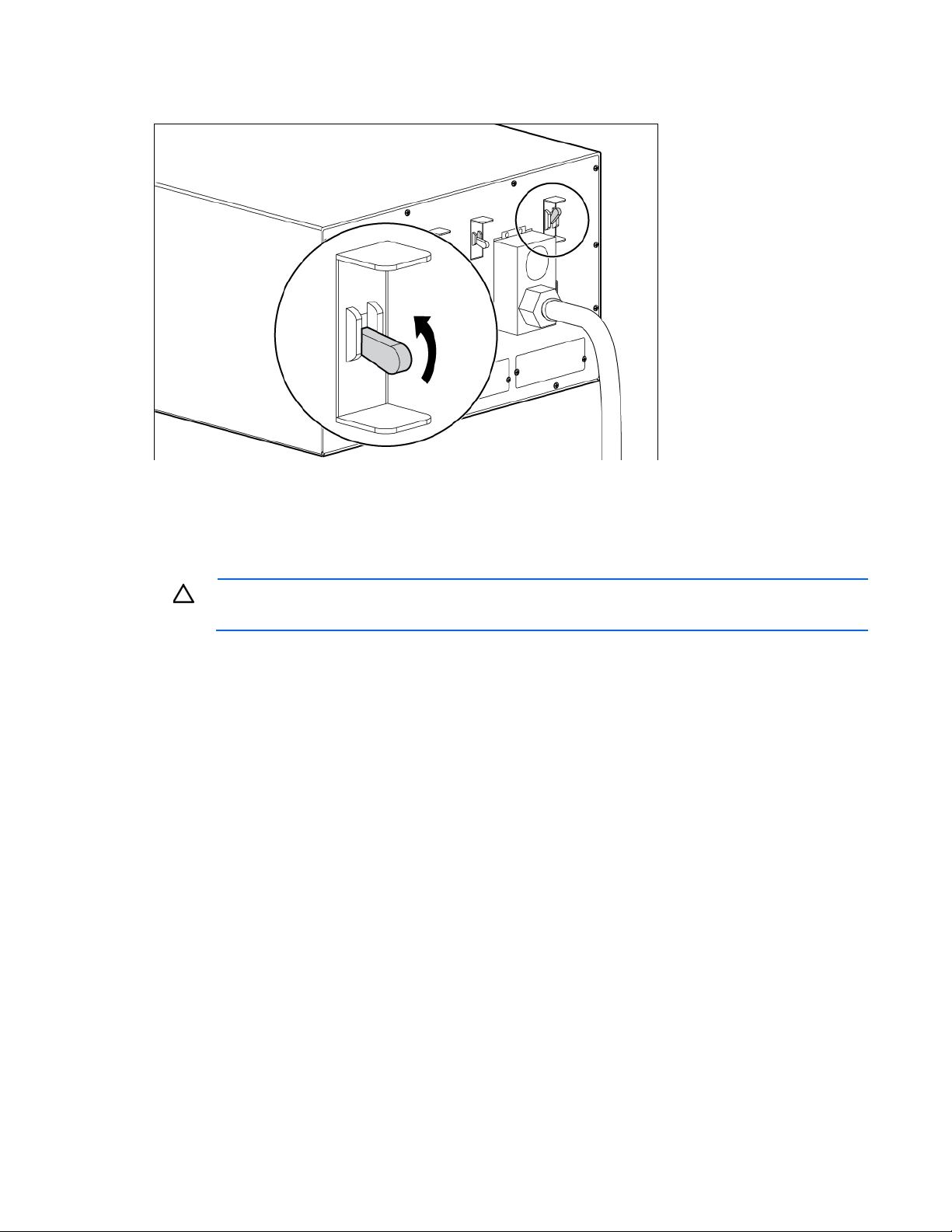
2. Pull the cord retention bracket away from the Bus Bar (1).
3. Connect the parallel input cord to the Bus Bar (2).
UPS installation 35
Page 36

4.
Secure the parallel input cord by pushing in the cord retention bracket (3).
UPS installation 36
Page 37

Switching on the UPS input circuit breaker
1. Switch the UPS input circuit breaker on each UPS to the On position.
2. Wait for the front panel display on each UPS to illuminate.
The Alarm LED flashes on each UPS.
3. Check each UPS front panel display for active alarms or notices (other than "Batteries Disconnected").
Resolve any active alarms before continuing. For alarm troubleshooting, see "LED and audible alarm
troubleshooting (on page 94)."
Switching on the UPS battery circuit breaker
When the UPS is plugged in and the battery circuit breaker is on, the UPS automatically enters Standby mode
and begins charging the batteries.
UPS installation 37
Page 38

Connecting devices to the UPS
CAUTION: Do not plug laser printers into the UPS output receptacles. The instantaneous current
Before connecting devices, verify that the UPS will not overload by checking that the ratings of the devices do
not exceed the UPS capacity. If the equipment rating is listed in amps, multiply the number of amps by the
nominal AC source to determine the VA.
To provide additional receptacles:
• For the 8kVA models—Plug a PDU into the UPS output receptacle at the end of the power cord.
• For the 12kVA models—
drawn by this type of printer can overload the UPS.
a. Install the included output module on the rear rack frame.
b. Plug the output module into the special UPS output receptacle, located on the rear of the UPS.
Item Description
1
2
3
4
5
6
Rack corner post
Mounting locations
Mounting top bracket
Output cord
Mounting bottom bracket
Input cord
Charging the UPS batteries
With the UPS in Standby mode, allow the batteries to charge before putting the UPS into service.
IMPORTANT: Charge the batteries for at least 48 hours before supplying backup power to
devices. The batteries charge to:
• 80 percent of their capacity within 5 hours
• 100 percent of their capacity within 48 hours
UPS installation 38
Page 39

Not powering down may cause an unexpected system shutdown or failure. To power down the
Powering up the parallel system
NOTE: Be sure that the total equipment ratings do not exceed the UPS capacity to prevent an
1. Be sure that the "Batteries Disconnected" alarm has cleared. Be sure that no other alarms appear on the
2. On any UPS, press any button on the front panel display to activate the menu options, and then press
3. Press the down arrow button to display the TURN UPS ON option. Press the right arrow button.
4. Confirm the selection. Press and hold the right arrow button for three seconds, until the UPS stops
5. Switch all output circuit breakers to the ON position.
6. On any UPS, press the ESC button until the HP logo appears.
7. To change any other factory-set defaults, see "UPS operations (on page 64)" .
overload alarm.
UPS front panel display. If the Alarm LED is flashing, do not proceed until all alarms clear. Check the
UPS status from the front panel to view the active alarms. Correct the alarms and restart if necessary.
the down arrow button until the TURN SYSTEM ON/OFF menu displays.
beeping.
Verify that the Power On LED illuminates solid on each UPS.
If the Alarm LED on any UPS is flashing, do not proceed until all alarms are clear. Check the UPS status
from the front panel to view the active alarms. Correct the alarms and restart if necessary. The UPS
should be in Normal mode.
NOTE: HP recommends setting the Date and Time and the Start screen.
8. If a REPO is installed, test the REPO function:
o Activate the external REPO switch. Verify the status change on the UPS display.
o Deactivate the external REPO switch and restart the UPS.
Adding an HP 3 Phase UPS to a parallel configuration
WARNING: This equipment must be installed by a licensed electrician or trained service
Disconnecting from utility power
For each additional UPS being installed, verify that all circuit breakers are in the Off position.
Installing the UPS
personnel familiar with high-power circuitry
CAUTION: Power down each UPS before installing an RP12000 UPS into an existing system.
UPS, see "Powering down the parallel system (on page 73)" .
Before installing the UPS, review and observe all warnings in "Precautions (on page 13)."
UPS installation 39
Page 40

WARNING: A risk of personal injury or damage to the equipment exists. Uneven loading of
equipment in the rack might cause the rack to become unstable. Install the heavier components
first, and then continue to populate the rack from the bottom to the top.
CAUTION: Always plan the rack installation so that the heaviest item is on the bottom of the rack.
Install the heaviest item first, and continue to populate the rack from the bottom to the top.
1. Install the mounting rails ("Installing the mounting rails" on page 56, "Installing the mounting rails" on
page 14).
2. With one person on each side of the carton, lift the chassis and lower it to the floor in front of the rack.
3. Install the mounting ears on the chassis using the screws provided.
4. With one person on each side, lift the chassis to rail level and slide the chassis on the mounting rails.
5. Attach the chassis to the rack using the supplied screws.
6. If using the rear mounting brackets, be sure that the bracket tabs are fully inserted into the rear panel
cutouts, then tighten the brackets.
UPS installation 40
Page 41

Configuring the Parallel UPS Card
1. Unpack the Parallel UPS Card, and be sure that the card was not damaged during shipment.
NOTE: If installing another X-Slot card, be sure to install the Parallel UPS Card in X-Slot
2. Remove the UPS X-Slot communication bay cover, and retain the screws.
3. Set the jumper pins on the Parallel UPS Card according to the parallel configuration.
Communication Bay 2.
For three or more paralleled UPSs:
o Set the cards of the first and last UPS to Pins 1 and 2.
o Set the card for the middle UPS(s) to Pins 2 and 3.
4. Install the Parallel UPS Card into an open X-Slot on the rear of the UPS.
5. Repeat steps 1 through 4 to install a Parallel UPS Card into each UPS to be paralleled.
The HP 3 Phase UPS parallel system automatically assigns identities to each UPS in the system based on
the order in which their Parallel UPS Cards are wired. For more information, see "Auto-identification (on
page 78)" .
6. Verify that all the terminal blocks and jumpers are installed in each UPS.
7. Using the supplied CAT 5 cables, install the Parallel UPS Card wiring between each UPS, connecting
the card OUT port on one UPS to the card IN port on the next UPS.
UPS installation 41
Page 42

When powering up the UPS, the parallel system identifies the UPS wired after UNIT 1 as UNIT 2, and
Standalone/parallel terminal block
so on.
Item Description
1
2
3
4
5
6
7
8
9
10
11
Standalone/parallel terminal block (removed)
For parallel use only
Redundant signal cable
For parallel use only
Standalone/parallel terminal block
UPS UNIT 1
UPS UNIT 2
Parallel UPS Card cable with ferrite
CAN OUT port
CAN IN port
UPS installation 42
Page 43

Item Description
12
8. Install the redundant signal wiring between the For Parallel Use Only and Standalone/Parallel terminals
UPS UNIT 3
on each UPS. Remove the existing terminal block connectors before installing the cable.
9. Secure the cable to the UPS using cable ties and plastic standoffs.
Be sure to check for correct polarity when installing the cable.
CAUTION: If polarity or wiring is not correct, the parallel system does not operate normally. For
example, when shutting down one UPS, the remaining UPS transfers the load to bypass instead of
10. Remove the Standalone/Parallel terminal block connector from the top UPS.
supporting the load. Be sure all wiring is correct for proper operation.
11. Tighten the screws securing each Parallel UPS Card in the X-Slot communication bay.
Removing the UPS battery bracket
Be sure that all circuit breakers on the rear panel of the UPS are in the Off position.
Installing the batteries
WARNING: To prevent personal injury, prepare the area and observe all materials-handling
procedures when transporting a battery module. Battery modules weigh 20 kg (44 lb).
UPS installation 43
Page 44

Replacing the UPS battery bracket
Attaching the UPS front bezel
1. Connect the cable to the electronics module.
UPS installation 44
Page 45

2.
Attach the UPS front bezel.
Connecting the ground bonding cable
The ground bonding screw is provided as an attachment point for conductors. Use a ground bonding cable
if the rack contains any conductors for the purpose of functional grounding or bonding of ungrounded metal
parts.
The ground bonding cable is not included.
Connecting the REPO port
This UPS has two REPO ports, normally-open and normally-closed. Before connecting to a REPO port, review
and observe all warnings.
WARNING: The pins on the REPO port are polarity sensitive. Be sure to verify polarity while
connecting the REPO port in parallel with other HP UPSs.
UPS installation 45
Page 46

WARNING: To meet the requirements stated in NEC (NFPA 70) Articles 645-10 and 645-11, a
UPS installed in a computer equipment room must be connected to a REPO circuit.
NOTE: Wire the connector block using stranded, nonshielded wire (AWG #22 - #18, or
equivalent).
HP recommends using different colors for the positive and negative wires.
To avoid inadvertant EPO:
• Minimize wire strain while connecting the REPO port.
• Avoid allowing the wires to hang in the rear of the UPS.
• Use tie wraps and tie wrap blocks to secure the wires tightly to the rack and the rear of the UPS.
For more information about the REPO port, see "REPO port (on page 10)" .
For information about verifying the REPO connection, see "Verifying the REPO port connection (on page 71)"
.
Connecting to a normally-open contact
IMPORTANT: The remote switch must be in the open position to enable power to the UPS output.
You can install an optional REPO circuit that shuts down the entire parallel system using a single switch. To
install a REPO switch for a parallel system, the selected REPO command (NO or NC) contacts from each UPS
in the system must be in parallel.
To install a REPO switch for a parallel system:
1. Verify that the UPS system is powered down and all power sources are removed. For more information,
see "Powering down the parallel system (on page 73)."
2. Mount the remote REPO switch. HP recommends mounting the REPO switch near the operator's
consoles or near the exit doors. For enclosure dimensions and wiring knockouts, see the REPO switch
manufacturer's installation instructions.
UPS installation 46
Page 47

3.
Connect the appropriate external switch to terminal block 4, normally-open REPO. Connect Pin 1 to Pin
1 and connect Pin 2 to Pin 2 of each UPS.
IMPORTANT: Always test the REPO function before applying the critical load to avoid accidental
load loss. For more information, see "Verifying the REPO port connection (on page 71)."
UPS installation 47
Page 48

4.
Reconnect terminal block 4, normally-open REPO, and then power on the UPS manually to restart. The
pins should remain open to keep the UPS running.
5. Verify that the jumper is inserted in terminal block 5.
Connecting to a normally-closed contact
IMPORTANT: The remote switch must be in the closed position to enable power to the UPS
output.
You can install an optional REPO circuit that shuts down the entire parallel system using a single switch. To
install a REPO switch for a parallel system, the selected REPO command (NO or NC) contacts from each UPS
in the system must be in parallel.
To install a REPO switch for a parallel system:
1. Verify that the UPS system is powered down and all power sources are removed. For more information,
see "Powering down the parallel system (on page 73)."
2. Mount the remote REPO switch. HP recommends mounting the REPO switch near the operator's
consoles or near the exit doors. For enclosure dimensions and wiring knockouts, see the REPO switch
manufacturer's installation instructions.
UPS installation 48
Page 49

3.
Connect the appropriate external switch to terminal block 5, normally-closed REPO. Connect Pin 1 to
Pin 1 and connect Pin 2 to Pin 2 of each UPS, and then discard the jumper from terminal block 5.
IMPORTANT: Always test the REPO function before applying the critical load to avoid accidental
load loss. For more information, see "Verifying the REPO port connection (on page 71)."
UPS installation 49
Page 50

4.
Reconnect terminal block 5, normally-closed REPO, and then power on the UPS manually to restart.
Short the pins to keep the UPS running. Maximum resistance is 10 ohm.
Connecting the UPSs to the Bus Bar
To connect the parallel input cord from each paralleled UPS to the Bus Bar in the rack:
1. Gently loop and twist the parallel input cords to minimize stress on the cords. The loop and twist for
each cord might vary depending on configuration and strain relief.
2. Pull the cord retention bracket away from the Bus Bar (1).
3. Connect the parallel input cord to the Bus Bar (2).
UPS installation 50
Page 51

4.
Secure the parallel input cord by pushing in the cord retention bracket (3).
Connecting the UPS to utility power
WARNING: To prevent injury from electric shock or damage to the equipment:
• Plug the input line cord into a grounded (earthed) electrical outlet that is installed near the
equipment and is easily accessible.
• Do not disable the grounding plug on the input line cord. The grounding plug is an important
safety feature.
Connect the UPS to a grounded utility power outlet.
• Do not use extension cords.
UPS installation 51
Page 52

Switching on the UPS input circuit breaker
1. Switch the UPS input circuit breaker on each UPS to the On position.
2. Wait for the front panel display on each UPS to illuminate.
The Alarm LED flashes on each UPS.
3. Check each UPS front panel display for active alarms or notices (other than "Batteries Disconnected").
Resolve any active alarms before continuing. For alarm troubleshooting, see "LED and audible alarm
troubleshooting (on page 94)."
Switching on the UPS battery circuit breaker
When the UPS is plugged in and the battery circuit breaker is on, the UPS automatically enters Standby mode
Connecting devices to the UPS
and begins charging the batteries.
UPS installation 52
Page 53

CAUTION: Do not plug laser printers into the UPS output receptacles. The instantaneous current
drawn by this type of printer can overload the UPS.
Before connecting devices, verify that the UPS will not overload by checking that the ratings of the devices do
not exceed the UPS capacity. If the equipment rating is listed in amps, multiply the number of amps by the
nominal AC source to determine the VA.
To provide additional receptacles:
• For the 8kVA models—Plug a PDU into the UPS output receptacle at the end of the power cord.
• For the 12kVA models—
a. Install the included output module on the rear rack frame.
b. Plug the output module into the special UPS output receptacle, located on the rear of the UPS.
Item Description
1
2
3
4
5
6
Rack corner post
Mounting locations
Mounting top bracket
Output cord
Mounting bottom bracket
Input cord
Charging the UPS batteries
With the UPS in Standby mode, allow the batteries to charge before putting the UPS into service.
IMPORTANT: Charge the batteries for at least 48 hours before supplying backup power to
devices. The batteries charge to:
• 80 percent of their capacity within 5 hours
Powering up the parallel system
• 100 percent of their capacity within 48 hours
UPS installation 53
Page 54

NOTE: Be sure that the total equipment ratings do not exceed the UPS capacity to prevent an
overload alarm.
1. Be sure that the "Batteries Disconnected" alarm has cleared. Be sure that no other alarms appear on the
UPS front panel display. If the Alarm LED is flashing, do not proceed until all alarms clear. Check the
UPS status from the front panel to view the active alarms. Correct the alarms and restart if necessary.
2. On any UPS, press any button on the front panel display to activate the menu options, and then press
the down arrow button until the TURN SYSTEM ON/OFF menu displays.
3. Press the down arrow button to display the TURN UPS ON option. Press the right arrow button.
4. Confirm the selection. Press and hold the right arrow button for three seconds, until the UPS stops
beeping.
Verify that the Power On LED illuminates solid on each UPS.
If the Alarm LED on any UPS is flashing, do not proceed until all alarms are clear. Check the UPS status
from the front panel to view the active alarms. Correct the alarms and restart if necessary. The UPS
should be in Normal mode.
5. Switch all output circuit breakers to the ON position.
6. On any UPS, press the ESC button until the HP logo appears.
7. To change any other factory-set defaults, see "UPS operations (on page 64)" .
NOTE: HP recommends setting the Date and Time and the Start screen.
8. If a REPO is installed, test the REPO function:
o Activate the external REPO switch. Verify the status change on the UPS display.
o Deactivate the external REPO switch and restart the UPS.
UPS installation 54
Page 55

ERM installation
Preparing to install the hardware
Before installing the hardware:
1. Be sure the necessary tools and materials (on page 13) are available.
2. Select an installation site ("Selecting a site" on page 14).
3. Prepare the equipment ("Readying the equipment" on page 14) for installation in the rack.
Tools and materials
The following tools are required for installation:
• Phillips screwdriver
• 10-mm hex-nut wrench
• T-25 Torx driver
A cage nut-fitting tool is supplied with the rack.
Selecting a site
WARNING: To prevent fire or electric shock, install the unit in a temperature- and
When selecting a site, consider the following factors:
• Elevated operating ambient temperature—If the equipment is installed in a closed or multi-unit rack
humidity-controlled indoor environment, free of conductive contaminants.
assembly, the operating ambient temperature of the rack environment might be greater than room
ambient temperature. Install the equipment in an environment compatible with the operating
temperature ("Environmental specifications" on page 103).
• Reduced air flow—In the rack, the rate of air flow required for safe operation of the equipment must not
be compromised.
• Circuit overloading—Consideration should be given to the connection of the equipment to the supply
circuit and the effect that overloading of the circuits might have on overcurrent protection and supply
wiring. Appropriate consideration of equipment nameplate ratings should be used when addressing
this concern.
• Reliable earthing—Reliable earthing of rack-mounted equipment should be maintained. Particular
attention should be given to supply connections other than direct connections to the branch circuit, such
as the use of power strips.
• Electrical requirements—All models require a dedicated (unshared) branch circuit, suitably rated for the
specific UPS as stated in "Input specifications" .
ERM installation 55
Page 56

Readying the equipment
1. Check the battery recharge date specified on the label that is affixed to the shipping carton.
IMPORTANT: Do not use the battery if the recharge date has passed. If the date on the battery
recharge date label has passed without the battery being recharged, contact an HP authorized
2. Transport the packaged unit to its installation location.
service representative for directions.
3. Unpack the equipment near the rack where the unit will be assembled.
Installing the mounting rails
WARNING: To reduce the risk of personal injury or damage to the equipment, be sure that:
• The leveling feet are extended to the floor.
• The full weight of the rack rests on the leveling feet.
• The stabilizing feet are attached to the rack if it is a single-rack installation.
• The racks are coupled together in multiple-rack installations.
• Only one component is extended at a time. A rack may become unstable if more than one
NOTE: Mounting hardware for square- and round-holed racks is included in the UPS kit.
1. Loosen the wing nuts or hex nuts, and then extend the brackets to the desired length.
component is extended for any reason.
ERM installation 56
Page 57

2.
Insert screws through the rack into the mounting rail and the front of each mounting bracket.
3. Install cage nuts or clip nuts into the rear of the rack.
ERM installation 57
Page 58

4.
Insert screws through the mounting rail into the cage nuts or clip nuts.
5. Tighten the wing nuts or hex nuts.
Preparing the rails for integrated shipping
If the unit is to be shipped in a rack:
1. Remove the hex nuts from the mounting rail.
2. Install the rail reinforcement plates and tighten using the hex nuts with captive washers, included in the
kit, instead of the nuts included with the rail.
ERM installation 58
Page 59

3.
Install the rear mounting brackets using hex nuts. Wait until the unit is installed and the brackets are
adjusted before tightening the nuts.
Switching off the UPS battery circuit breaker
WARNING: To prevent the UPS from dropping the load, be sure to switch off only the UPS
battery circuit breaker.
Once the battery circuit breaker is switched off, an audible alarm sounds, the Alarm LED flashes, and the LCD
displays, "Battery not connected."
To silence an audible alarm, see "Silencing an audible alarm (on page 71)" .
Switching off the ERM circuit breaker
ERM installation 59
Page 60

WARNING: To prevent personal injury from electric shock or damage to the equipment, verify
that the circuit breaker is in the Off position.
Installing the ERM
Before installing the ERM, review and observe all warnings in "Precautions (on page 13)."
WARNING: A risk of personal injury or damage to the equipment exists. Uneven loading of
equipment in the rack might cause the rack to become unstable. Install the heavier components
1. Install the mounting rails ("Installing the mounting rails" on page 56, "Installing the mounting rails" on
2. With one person on each side of the carton, lift the chassis and lower it to the floor in front of the rack.
first, and then continue to populate the rack from the bottom to the top.
CAUTION: Always plan the rack installation so that the heaviest item is on the bottom of the rack.
Install the heaviest item first, and continue to populate the rack from the bottom to the top.
page 14).
ERM installation 60
Page 61

3.
Install the mounting ears on the chassis using the screws provided.
4. With one person on each side, lift the chassis to rail level and slide the chassis on the mounting rails.
5. Attach the chassis to the rack using the supplied screws.
6. If using the rear mounting brackets, be sure that the bracket tabs are fully inserted into the rear panel
cutouts, then tighten the brackets.
The UPS auto-detects ERM installation by updating the system runtime. If the system runtime is not updated,
verify installation or see "Troubleshooting (on page 94)" .
ERM installation 61
Page 62

Attaching the ERM front bezel
Connecting the ERM to the UPS
NOTE: To install a second ERM, plug the cable from the second ERM into the socket at the rear
of the first ERM. Up to four ERM units can be connected.
ERM installation 62
Page 63

Switching on the ERM circuit breaker
Switching on the UPS battery circuit breaker
When the UPS is plugged in and the battery circuit breaker is on, the UPS automatically enters Standby mode
and begins charging the batteries.
Charging the ERM batteries
Connect the UPS to a grounded utility power outlet. When the UPS is plugged in, it automatically enters
Standby mode and begins charging the ERM batteries. With the UPS in Standby mode, allow the ERM
batteries to charge for at least 24 hours before putting the UPS into service.
ERM installation 63
Page 64

UPS operations
Mimic screen
The Mimic screen shows the internal components of the UPS and a real-time display of the operating status.
A thicker bar indicates that the node is energized.
Modes of operation
The UPS has four modes of operation:
• Standby mode (on page 64)
• Normal mode (on page 65)
• Battery mode (on page 66)
Standby mode
• Auto-Bypass mode (on page 66)
In Standby mode:
• No power is available at the UPS output receptacles.
• The UPS charges the batteries as necessary.
The UPS can be placed in Standby mode when the UPS is in Normal mode (on page 65).
To place the UPS in Standby mode:
1. Power down the UPS.
UPS operations 64
Page 65

o
Standalone UPS configuration—See "Powering down the standalone UPS (on page 72)."
o Individual UPS in a parallel configuration—See "Powering down an individual paralleled UPS (on
page 72)."
o Parallel UPS configuration—See "Powering down the parallel system (on page 73)."
2. Power to the load ceases.
IMPORTANT: While in Standby mode, the UPS maintains the charge on the batteries, but no
power is available at the output receptacles. The UPS remains in Standby mode until an alternate
mode is selected or until utility power is removed.
Normal mode
In Normal mode:
• Power is available at the UPS receptacles.
• The UPS charges the batteries as necessary.
Depending on input power conditions, the UPS automatically changes modes. The UPS has three types of
Normal mode:
• Standard mode (on page 65)
• Full-Time Standard mode (on page 65)
• High Efficiency mode (on page 65)
Standard mode
If the input line exceeds normal operating range, the UPS transfers to Standard mode (Online mode) to
produce a regulated output voltage. When the input line returns to normal operating range, the UPS returns
to High Efficiency mode (on page 65).
Full-Time Standard mode
Full-Time Standard mode (continuous Online mode) is user selectable for full-time operation.
High Efficiency mode
By default, the UPS operates in a High Efficiency mode that minimizes heat contribution to the rack
environment. The system bypass input directly supplies the system output with three-phase AC power, and the
UPS automatically transfers to double-conversion (Normal mode (on page 65)) operation as needed. The
battery recharges as necessary.
Continuous double-conversion mode
Continuous double-conversion mode is available only for loads less than 10 kW (86%). If the load exceeds
the 10 kW limit while in Standard mode, the UPS switches to High Efficiency mode until the load is reduced
below 9 kW. After three attempts within one hour to operate in Standard mode, the UPS locks into High
Efficiency mode for one hour to prevent continuous cycling.
UPS operations 65
Page 66

Transferring the UPS between Normal modes
To transfer between Normal mode and Full-Time Standard mode:
1. Press any button to activate the menu options.
2. Select SETTINGS, USER SETTINGS, POWER STRATEGY, STANDARD, and ENTER to confirm.
To transfer between Standard mode and Normal mode:
1. Press any button to activate the menu options.
2. Select SETTINGS, USER SETTINGS, POWER STRATEGY, HIGH EFFICIENCY, and ENTER to confirm.
Alternatively, press any button to activate the menu options, then select TURN UPS ON/OFF, TURN UPS
ON, and ENTER to confirm.
Battery mode
In Battery mode, the UPS supplies power without being connected to utility power.
To power up the UPS without using utility power, connect to AC power at least one time.
When utility power returns, the UPS enters Normal mode (on page 65) while the batteries recharge.
Auto-Bypass mode
The UPS automatically enters Auto-Bypass mode when:
• Auto-Bypass mode is activated through the front panel.
• The UPS detects the electronics module s being replaced.
• The UPS detects that the control panel is disconnected from the electronics module.
• The UPS detects an internal failure.
• The UPS detects an overtemperature condition.
• The UPS has an overload condition.
For more information about the conditions that put the UPS into Auto-Bypass mode, see "Troubleshooting (on
page 94)."
To place the UPS in Auto-Bypass mode:
1. Verify that all UPS circuit breakers are in the Off position.
2. Verify that the UPS power cord is connected to an AC outlet.
3. Switch on utility power where the UPS is connected.
4. Switch the UPS input circuit breaker to the On position.
Wait for the UPS front panel display to illuminate. The Alarm LED flashes.
5. Check the UPS front panel display for active alarms or notices (other than "Batteries Disconnected").
Resolve any active alarms before continuing. To resolve alarms, see "Troubleshooting (on page 94)."
6. Switch the UPS battery circuit breaker to the On position.
7. If optional ERMs are installed, switch all ERM battery circuit breakers to the On position.
8. Verify that the "Batteries Disconnected" alarm has cleared.
Verify that no other alarms appear on the UPS front panel display.
UPS operations 66
Page 67

9.
Press any button to activate the menu options.
10. Select CONTROL, GO TO BYPASS MODE.
The Auto-Bypass and Power On LEDs illuminated solid, indicating the UPS is operating in Auto-Bypass
mode. The load is now powered by utility power.
11. Switch the load connector circuit breaker to the On position.
12. Press ESC until the HP logo appears.
Transferring the UPS between modes
To transfer between Normal mode and Auto-Bypass mode:
1. Press any button to activate the menu options.
2. Select CONTROL, GO TO BYPASS MODE, and ENTER to confirm.
To transfer between Auto-Bypass mode and Normal mode:
1. Press any button to activate the menu options.
2. Select CONTROL, GO TO NORMAL MODE, and ENTER to confirm.
Alternatively, press any button to activate the menu options, then select TURN UPS ON/OFF, TURN UPS
ON, and ENTER to confirm.
Configuring the UPS
NOTE: If ERMS are used in a parallel system
• Each UPS must have its own ERM.
• Each UPS must have the same number of ERMs per UPS to ensure consistent
NOTE: Standalone and parallel UPSs automatically detect the number of ERMs connected.
runtimes.
Changing the language
Press and hold the far left button for approximately five seconds to select the language menu. This action is
possible from any LCD menu screen.
Changing display functions
As the default or after 15 minutes of inactivity, the LCD displays the selectable startup screen. The default is
the HP logo and can be changed to the Mimic screen (on page 64) in the User Settings menu.
The backlit LCD automatically dims after a long period of inactivity. Press any button to restore the screen.
Press any button to activate the menu options. Use the up and down arrow buttons to scroll through the menu
structure. Press the right arrow button to enter a submenu. Press the right arrow button to select an option.
Menu map for display functions
Press the ESC/left arrow button to cancel or return to the previous menu.
UPS operations 67
Page 68

NOTE: Menu functions related to parallel systems appear only on paralleled UPSs.
System Normal | High Efficiency Power: % /
•
•
•
•
Main menu Submenu Display information or menu function
UPS Status
Event Log
Measurements
Control
Battery Resting | Battery Floating UPS in Parallel
mode / Parallel Unit Number x / Units on Bus
Bar / Units on Load
Parallel system kW (by unit) / kW (Parallel total)
Output Voltage L-N and L-L / Current / Frequency /
Battery Voltage / Current / Runtime
Input Voltage L-N and L-L / Current / Frequency
Load Receptacle Voltage / Current / Power kW / Power kVA /
Go to Bypass mode Transfers the UPS system to internal Auto-Bypass
Displays up to 100 events and alarms
Power kW / Power kVA / Power pf
Frequency
mode
When this command is active, the option
changes to Go to Normal mode.
Settings
Identification
Turn UPS On/Off
Start Battery Test Schedules a battery test. The battery test might
Display Test Four different selectable tests for the front panel
User Settings For more information, see "Changing user
Service Settings Not available
On and Off Option UPS On / UPS Off / System On / System Off
Changing user settings
Description Available settings Default setting
Set Date and Time
Display Contrast
Change Language
not start immediately.
functions:
The LEDs cycle through
The alarm sounds
The backlight turns off and on
The pixels scroll through to test the LCD
settings (on page 68)."
UPS Type / Part Number / Serial Number /
Firmware / Display / System / Parallel Card
Set Year, Month, Day
Date: mm/dd/yyy 01/01/2003
Set Hours, Minutes 00:00
Time is a 24-hour clock
Adjust contrast with up/down arrow
buttons
Set Language English
Moderate
UPS operations 68
Page 69

Description Available settings Default setting
Parallel XCP: [System][Sub Unit]
System
[High Efficiency][Standard]
High Efficiency
[Normal Sound][Disabled]
Normal Sound
[Allowed][Not Allowed]
Not Allowed
Relay Config
Signal Inputs
Serial Port Config
Parallel Operation Settings (only
available in parallel configuration)
Relay: [Alarm-1][X-Slot 1-1/2/3/4] or
[X-Slot 2-1/2/3/4]
Setup: [On Battery][Summary Alarm][On
Bypass][UPS OK][custom][empty]
[empty][Logic]
For more information, see "Programmable
signal inputs (on page 77)."
Port: [X-Slot-1][X-Slot 2/Serv]
Speed: [19200][9600][2400][1200] 19200
Parallel Operation Mode: [Redundant
Mode][Capacity Mode]
This setting is not available for six-unit
systems (Redundant Mode only)
Alarm 1: empty
X-Slots (1 or 2)
#1: UPS OK
#2: On Bypass
#3: Summary Alarm
#4: On Battery
<empty>
Redundant Mode
Select System for HP communication
applications. Select Sub Unit for other
applications.
Battery Setup
Power Strategy
Start Screen
User Password
Audible Alarms
Unsynchronized Transfer to
Bypass
Transfer to Bypass When
Overload
Automatic Start Delay
Control Commands from X-Slot 1
Control Commands from X-Slot
2/Serv
X-Slot Signal Input Activation
Auto ID Restart: [Done][Restart]
Select Restart to reinitialize
auto-identification. For more information,
see "Auto-identification (on page 78)."
Number of ERMs: [0 through 4]
For more information, see "Configuring the
UPS (on page 67)."
Battery Low Alarm Level:
[1.750 through 1.950 volts per cell]
Automatic Battery Tests:
[Enabled][Disabled]
Enabled automatically runs the battery test
once a month.
For more information, see "Normal mode
(on page 65)."
HP logo
Mimic screen (on page 64)
[Enabled][Disabled]
If enabled is selected, the password is
USER.
[After a delay][Immediately] After a delay
-1 through 32767 seconds
(-1 means disabled)
[Allowed][Not Allowed] Allowed
[Allowed][Not Allowed] Allowed
0 through 65 seconds 5s
None
0
(internal batteries only)
1.880 V/cell
Enabled
HP logo
Disabled
0s
UPS operations 69
Page 70

Description Available settings Default setting
Delay
Site Wiring Fault Notice
Reset Custom Event Settings
REPO Configuration
[Enabled][Disabled] Enabled
0 through 32 Total: 0/32
[Enabled][Disabled] Enabled
Setting the Battery Low alarm level
The default Battery Low alarm level setting provides approximately 2.5 minutes of battery warning for a UPS.
Additional ERMs installed in a parallel system can provide a longer warning time.
To set the Battery Low Alarm Level:
1. Press any button to activate the menu options.
2. Select SETTINGS > USER SETTINGS > BATTERY SETUP > Automatic Battery Tests.
3. Use the up or down arrow buttons to select the volts per cell. For a list of settings, see the table below.
4. Press the left arrow button to save the setting.
5. Press and hold the ESC button until the Start screen appears.
Warning time
(in minutes)
2
2
2
2
3
3
3
3
4
4
4
4
5
5
5
5
Values are approximate.
Number of ERMs
installed
Battery Low Alarm Level (user setting)
20% Load 50% Load 100% Load
1 1.783 1.821 1.854
2 1.776 1.811 1.831
3 1.772 1.798 1.818
4 1.768 1.781 1.805
1 1.805 1.848 1.981
2 1.793 1.833 1.859
3 1.787 1.820 1.843
4 1.781 1.803 1.831
1 1.822 1.868 1.918
2 1.807 1.850 1.883
3 1.789 1.836 1.866
4 1.793 1.818 1.850
1 1.835 1.884 1.941
2 1.818 1.863 1.903
3 1.799 1.849 1.883
4 1.803 1.823 1.865
UPS operations 70
Page 71

Running automatic battery tests
Battery tests rely on backfeeding the utility, using the utility as a load. Some sites might choose to disable
battery testing if their source is not capable of being backfed. Examples of such sources include generators,
other UPSs, and other stiff or soft sources. If a source is not capable of being backfed, the UPS aborts the test
(due to utility failure) and maintains the load and log the event. Further consequences depend on the source
(for example, another UPS feeding the BladeUPS module might trip off).
NOTE: For automatic and manual battery tests, the UPS determines when it is appropriate to run
To disable battery testing:
1. Press any button on the front panel display to activate the menu options.
2. Select SETTINGS > USER SETTINGS > BATTERY SETUP > Battery Low Alarm.
3. Use the up or down arrow buttons to select Disabled.
4. Press the left arrow button to save the setting.
the test. Battery tests run only when the system is in High Efficiency mode.
5. Press and hold the ESC button until the Start screen appears.
Testing the front panel display
To test the LEDs:
1. Press any button to activate the menu options.
2. Select CONTROL, DISPLAY TEST
3. Confirm the selection by pressing the right arrow button.
Press ESC to stop the test.
Silencing an audible alarm
To silence an alarm, press any button on the front panel display to silence the alarm. If the alarm status
changes, the alarm beeps again, overriding the previous alarm silencing.
IMPORTANT:
• Although the audible alarm silences, the condition that caused the alarm to sound may still
exist.
For information about audible alarm conditions, see "LED and audible alarm troubleshooting (on page 94)."
• If a utility power failure caused the alarm, the alarm silences after power is restored.
Verifying the REPO port connection
NOTE: While testing, operate connected equipment in a safe test mode so the effects do not
After connecting the REPO port (on page 21):
1. Initiate a REPO by closing the REPO contact.
disrupt critical operations.
UPS operations 71
Page 72

CAUTION: If the polarity is reversed while connecting the REPO port, the UPS powers up
normally.
2. Power up the UPS.
o Standalone UPS configuration—See "Powering up the standalone UPS (on page 25)."
o Parallel UPS configuration—See "Powering up the parallel system (on page 39)."
3. Verify proper connection of the REPO port:
a. Disconnect the REPO port.
b. Reconnect the REPO port.
If the polarity is correct, the REPO connectors can be disconnected, and then reconnected, without
initiating a REPO.
c. Verify that the UPS remains in Normal mode (on page 65).
d. If a REPO is initiated, the polarity is reversed. Check and correct the connections.
Powering down the standalone UPS
1. Switch the output circuit breaker to the Off position.
2. Press any button on the front panel display to activate the menu options.
3. Select TURN UPS ON/OFF, TURN UPS OFF, and press the right arrow button.
4. Confirm the selection. Press and hold the right arrow button for three seconds, until the UPS stops
beeping.
The output relays open, the UPS transfers to Standby mode (on page 64), and the Power On LED turns
off.
5. Switch the UPS battery circuit breaker to the Off position.
6. If optional ERMs are installed, switch all ERM battery circuit breakers to the Off position.
7. Switch the UPS input circuit breaker to the Off position.
8. Press ESC until the HP logo appears.
9. Disconnect the UPS from utility power.
Powering down an individual paralleled UPS
1. Switch the output circuit breaker to the Off position.
2. Press any button on the front panel display to activate the menu options.
3. Select the TURN UPS ON/OFF, TURN UPS OFF, and press the right arrow button.
4. Confirm the selection. Press and hold the right arrow button for three seconds, until the UPS stops
beeping.
The output relays open, the UPS transfers to Standby mode, and the Power On LED turns off.
5. Switch the UPS battery circuit breaker to the Off position.
6. If optional ERMs are installed, switch all ERM battery circuit breakers to the Off position.
7. Switch the UPS input circuit breaker to the Off position.
8. Press ESC until the HP logo appears.
UPS operations 72
Page 73

NOTE: If there is only one circuit breaker for all UPSs, do not switch off utility power until all UPSs
are powered down.
9. Disconnect the UPS from utility power.
If you are shutting down all the UPSs in a parallel system , repeat steps 1 through 7 for each UPS, then
disconnect from utility power.
Powering down the parallel system
1. Switch one UPS load connector circuit breaker to the Off position.
2. Press any button on the front panel display to activate the menu options.
3. Select the TURN UPS ON/OFF, TURN SYSTEM OFF, and press the right arrow button.
4. Confirm the selection. Press and hold the right arrow button for three seconds, until the UPS stops
beeping.
The UPS removes power to the parallel UPS system output.
The output relays open, the UPS transfers to Standby mode, and the Power On LED turns off.
5. Switch the UPS battery circuit breaker to the Off position.
6. If optional ERMs are installed, switch all ERM battery circuit breakers to the Off position.
7. Switch the UPS input circuit breaker to the Off position.
8. Press ESC until the HP logo appears.
9. To completely remove power from the UPSs, continue to "Powering down the standalone UPS (on page
72)" to power down each UPS.
UPS operations 73
Page 74

Communication
Standalone/parallel
Installing communication options and control terminals
Item Description
1
2
3
4
5
6
7
8
9
10
Signal input 1
Signal input 2
REPO (normally open)
REPO (normally closed)
DB-9 communication port
Redundant signal wiring (for parallel use only)
Relay output contacts
Option card bay 1
Option card bay 2
To install the communication options and control terminals:
1. Install the appropriate option card and/or necessary cable(s).
2. Connect the cables to the appropriate locations.
For detailed information, see "Communication options (on page 75)" or "Control terminals (on page
76)."
3. Route and tie the cable(s) out of the way.
4. Power up the UPS.
Communication 74
Page 75

o
Standalone UPS configuration—See "Powering up the standalone UPS (on page 25)."
o Parallel UPS configuration—See "Powering up the parallel system (on page 39)."
Communication options
The UPS has serial communication capabilities through the DB-9 communication port or through an X-Slot
card in one of the available bays.
The UPS supports two serial communication devices.
NOTE: Relay, signal inputs, and the serial port baud rates are configurable through the front
X-Slot 1 (independent) X-Slot 2 (multiplexed) DB-9 communication port (multiplexed)
HP UPS Management Module
HP UPS Management Module
DB-9 communication port
To establish communication between the UPS and a computer, connect the computer to the UPS
communication port using the supplied communication cable.
For the communication port location, see "Installing communication options and control terminals (on page
74)."
panel menus.
HP Parallel UPS Card Available
Not in use Available
Serial communications port pin assignment
Pin number Signal name Function Direction from the UPS
1
2
3
— No connection —
TxD Transmit to external device Out
RxD Receive from external device In
Communication 75
Page 76

Pin number Signal name Function Direction from the UPS
4
5
6
7
8
9
— No connection —
GND Signal common (tied to chassis) —
— No connection —
— No connection —
— No connection —
— No connection —
Control terminals
The cables should be connected to the control terminal with a mating connector. Input and output terminals
have a functional isolation from terminal to terminal. They are connected to the UPS chassis through
individual 1 MW resistors.
If using a semiconductor switch type, pay attention to the proper polarity. A relay or other mechanical control
is preferred.
Relay output contacts
WARNING: The relay output contacts must not be connected to any utility connected circuits.
Reinforced insulation to the utility is required. The relay output contacts have a maximum rating of
30 VAC/1 A and 60 Vdc/2 A nominal values.
Communication 76
Page 77

The UPS incorporates a programmable relay output with potential free contacts for remote alarm indications.
These alarms can be activated separately or at the same time with other building
An additional four relay outputs can be obtained with the compatible Relay Interface option card.
Programmable signal inputs
The UPS incorporates two programmable signal inputs. HP recommends using non-polar (relay) control input.
The pins must be shorted with maximum resistance of 10 ohm in order to activate the specific input.
Verify control terminal connections if polarity control is required.
Signal Description
empty
Not in use (default)
building alarm 1-2
alarms.
Building alarms are local only to the UPS.
on generator
ext battery breaker
request bypass
force bypass
on/OFF
If active, the High Efficiency setting is disabled (BladeUPS 12i model only) and
1
battery tests are disabled.
If active, the UPS knows that the external batteries are disconnected.
2
If active, the UPS transfers the load to bypass when the bypass voltage,
frequency, and phase rotation are within the allowed limits.
1
If active, the UPS is forced to static bypass operation regardless of the bypass
1
status.
If active, the UPS output powers down regardless of the mode of operation.
Auxiliary power, communication, and rectifier/battery charger remain
functional. Restart is initiated immediately when the signal is inactive.
charger off
If active, the battery charge function is disabled. In a utility power outage, the
discharge of batteries is supported.
1
Program for only one UPS in a parallel system.
2
Program for all UPSs in a parallel system.
2
2
Use the programmable signal inputs to emulate some of the features usually seen on larger 3-phase systems.
For example:
• Configure the signal from a smoke detector or water leak detector to power down the system.
• Configure a vibration sensor or air conditioner sensor to power down the system.
• Set actions for alarms from a generator, such a disabling the charger for an undersized generator or
shutdown for a failed generator.
• Configure an ATS sensor to transfer the system to Auto-Bypass mode.
Parallel communication
The Parallel UPS Card in each paralleled UPS provides connectivity for system metering and operational
mode control. Powering up, powering down, and auto-calibration commands given at one UPS also
command the other UPSs in the parallel system. The UPSs in a parallel system are in constant communication
to monitor settings and status information.
Communication 77
Page 78

Mode transfers
• If one UPS in a parallel system transfers from High Efficiency mode (on page 65) to Normal mode (on
page 65), the other UPSs transfer also.
• If one UPS transfers to Battery mode (on page 66), the remaining UPSs in the parallel system stay online.
The transferred UPS might transfer back to online at any time, and the parallel system resynchronizes.
• When a parallel system is on battery power , the front panels of each UPS display the battery status
information of the UPS with the lowest runtime remaining. When the first UPS shuts down, the other UPSs
also shut down.
• In a parallel system configured for redundancy, the UPSs use a distributed bypass, and the following
alarms cause an individual UPS to power down instead of transferring to Auto-Bypass mode (on page
66):
o Failure of the fan, fuse, temperature sensor, or power supply
o Inverter AC under voltage
o Battery current limit
o DC line under voltage
o Battery over voltage
Redundant signal wiring
The redundant signal wiring provides redundant backfeed protection in case of Parallel UPS Card failure in
the parallel system. If the card fails, the UPSs transfer to Normal mode (on page 65). The system runs
unsynchronized, and any UPS can transfer to Battery mode (on page 66) as necessary. If any UPS must
transfer to Auto-Bypass mode (on page 66), the redundant signal wiring allows the entire parallel system to
transfer to Auto-Bypass mode, without backfeeding.
Auto-identification
The UPS parallel system automatically assigns identities to each UPS in the system. To take advantage of this
feature, wire the Parallel UPS Cards together. For more information, see "Installing in a parallel configuration
(on page 26)."
Upon powering up the UPS, the UPS with the initializing jumper installed identifies itself as UNIT 1. The next
UPS wired identifies itself as UNIT 2, and so forth. The auto-identification sequence takes about 15-20
seconds to complete after all the UPSs in the parallel system have logic power.
If a UPS is powered down or otherwise loses logic power, the UPS re-identifies itself in the proper sequence
after logic power is restored.
If a UPS is powered down and removed from the parallel system, the other UPSs in the system do not
re-identify themselves to compensate for the missing UPS until logic power to all the UPSs is cycled. For
example, if you remove UNIT 2 and rewire UNIT 3's Parallel UPS Card IN port to UNIT 1's Parallel UPS Card
OUT port, UNIT 3 does not re-identify itself as UNIT 2 until logic power is cycled. The Parallel UPS Cards for
UNIT 1 and UNIT 3 continue to function normally without the need to re-identify.
Communication 78
Page 79

Metering
The Output and Load Receptacle meter readings differ between a parallel system and a standalone UPS. In
a parallel system, one UPS reads the Load Receptacle value for the total system (the others read zero), but
each UPS displays its own Output value. For example, in a two-unit parallel system with one Anderson load
connection for 12 kVA, the Load Receptacle current would read 12 kVA on one UPS and zero on the other
UPS, but the Output measurement would be 6 kVA on each UPS (half the total). In a standalone UPS, the load
can be connected from the outlet cord or the Anderson load connector. The Output measurement would be
the total load on the UPS, and the Load reading would be the portion supplied by the Anderson load
connector.
Communication 79
Page 80

Power management
HP UPS Power Protection Agent overview
The HP UPS Power Protection Agent runs on a local or network server and allows the management module
to gracefully shut down the operating system of that server and optionally run a script during power failure.
Install the agent on any machine that is powered by the UPS and any machine that the management module
uses to initiate a command.
NOTE: If you are an existing HP Power Manager user, you must uninstall the HPPM Remote
Features
• Monitors the status of the UPS and performs diagnostics
Agent before installing the UPS Power Protection Agent.
• Manages a graceful shutdown of attached equipment during a utility power failure
• For UPSs with multiple load segments, the management module, manages independent UPS load
segments to provide separate power control of connected equipment
NOTE: The HP 3 Phase UPSs have only one load segment.
• Prioritizes the timing of equipment shutdown and reboots connected equipment by load segment
• Delays restart by load segment after a power outage to sequence the startup of system components
• Shuts down and reboots the UPS and attached equipment, based on a user-specified schedule
• Sends customized email and broadcast notification messages and SNMP traps
• Issues computer commands at power failure
• Displays logs for analysis
• Supports a redundant UPS configuration
• Includes enhanced HP SIM integration
• Includes multi-language support
• Supports serial- and network-attached server communications
• Supports a customizable Events script
Power management 80
Page 81

Maintenance
Removing the UPS front bezel
Removing the ERM front bezel
Replacing the UPS electronics module
Maintenance 81
Page 82

NOTE: Do not disconnect the electronics module while the UPS is in Battery mode.
This component is hot-swappable and can be replaced without powering down the UPS. However, Battery
mode is not available and the load is not protected.
1. (optional) To replace the component with the UPS powered down, do one of the following:
o Standalone UPS configuration—See "Powering down the standalone UPS (on page 72)."
o Individual UPS in a parallel configuration—See "Powering down an individual paralleled UPS (on
page 72)."
o Parallel UPS configuration—See "Powering down the parallel system (on page 73)."
2. Do one of the following:
o Standalone UPS configuration—Transfer the UPS to Auto-Bypass mode (on page 66).
o Parallel for capacity configuration—Transfer the UPS to Auto-Bypass mode (on page 66).
o Parallel for redundancy configuration—No mode transfer is necessary. If the UPS is operating in a
parallel for redundancy configuration when the electronics module is replaces, the load
automatically transfers to the remaining UPSs.
NOTE: Disconnecting the control panel from the electronics module automatically transfers the
UPS to Auto-Bypass mode. However, HP recommends transferring the UPS to Auto-Bypass mode
manually BEFORE disconnecting the control panel to provide extra protection to the electronics
3. If the configuration is parallel, disconnect the redundant signal cable(s) from the UPS.
module.
For the location of the redundant signal cable, see "Configuring the Parallel UPS Card (on page 41)."
4. Remove the UPS front bezel ("Removing the UPS front bezel" on page 81).
5. Remove the screw securing the electronics module and slide the module out.
6. Replace the electronics module. Be sure the electronics module is firmly seated in the connector.
Maintenance 82
Page 83

7.
Replace the screw.
8. If the configuration is parallel, reconnect the redundant signal cables.
9. Replace the front bezel.
10. Transfer the UPS to Normal mode (on page 65).
Replacing UPS X-Slot cards
This component is hot-swappable and can be replaced without powering down the UPS.
1. (optional) To replace the component with the UPS powered down, do one of the following:
o Standalone UPS configuration—See "Powering down the standalone UPS (on page 72)."
o Individual UPS in a parallel configuration—See "Powering down an individual paralleled UPS (on
page 72)."
o Parallel UPS configuration—See "Powering down the parallel system (on page 73)."
2. Disconnect the communications cable from the X-Slot Card.
Maintenance 83
Page 84

3.
Remove the two screws securing the X-Slot Card and slide the card out.
To replace the component, reverse the removal procedure.
NOTE: Replacing the HP Management Module might require power management software to be
restarted or reconfigured.
Configuring the Parallel UPS Card
1. Unpack the Parallel UPS Card, and be sure that the card was not damaged during shipment.
NOTE: If installing another X-Slot card, be sure to install the Parallel UPS Card in X-Slot
2. Remove the UPS X-Slot communication bay cover, and retain the screws.
3. Set the jumper pins on the Parallel UPS Card according to the parallel configuration.
Communication Bay 2.
For three or more paralleled UPSs:
o Set the cards of the first and last UPS to Pins 1 and 2.
Maintenance 84
Page 85

o
Set the card for the middle UPS(s) to Pins 2 and 3.
4. Install the Parallel UPS Card into an open X-Slot on the rear of the UPS.
5. Repeat steps 1 through 4 to install a Parallel UPS Card into each UPS to be paralleled.
The HP 3 Phase UPS parallel system automatically assigns identities to each UPS in the system based on
the order in which their Parallel UPS Cards are wired. For more information, see "Auto-identification (on
page 78)" .
6. Verify that all the terminal blocks and jumpers are installed in each UPS.
7. Using the supplied CAT 5 cables, install the Parallel UPS Card wiring between each UPS, connecting
the card OUT port on one UPS to the card IN port on the next UPS.
Maintenance 85
Page 86

When powering up the UPS, the parallel system identifies the UPS wired after UNIT 1 as UNIT 2, and
Standalone/parallel terminal block
so on.
Item Description
1
2
3
4
5
6
7
8
9
10
11
Standalone/parallel terminal block (removed)
For parallel use only
Redundant signal cable
For parallel use only
Standalone/parallel terminal block
UPS UNIT 1
UPS UNIT 2
Parallel UPS Card cable with ferrite
CAN OUT port
CAN IN port
Maintenance 86
Page 87

Item Description
12
8. Install the redundant signal wiring between the For Parallel Use Only and Standalone/Parallel terminals
UPS UNIT 3
on each UPS. Remove the existing terminal block connectors before installing the cable.
9. Secure the cable to the UPS using cable ties and plastic standoffs.
Be sure to check for correct polarity when installing the cable.
CAUTION: If polarity or wiring is not correct, the parallel system does not operate normally. For
example, when shutting down one UPS, the remaining UPS transfers the load to bypass instead of
10. Remove the Standalone/Parallel terminal block connector from the top UPS.
supporting the load. Be sure all wiring is correct for proper operation.
11. Tighten the screws securing each Parallel UPS Card in the X-Slot communication bay.
Replacing the batteries
To replace the batteries:
1. Read and observe the requirements in "Important battery safety information (on page 87)" and "Battery
care and storage guidelines (on page 87)."
Important battery safety information
2. Follow the instructions in "UPS battery replacement procedure (on page 88)."
WARNING: The unit contains sealed lead-acid battery modules. To prevent fire or chemical
burns:
• Do not attempt to recharge batteries after removal from the unit.
• Do not disassemble, crush, or puncture the batteries.
• Do not short the external contacts of the batteries.
• Do not immerse the batteries in water.
• Do not expose to temperatures higher than 60°C (140°F).
WARNING: To prevent personal injury from hazardous energy:
• Remove watches, rings, or other metal objects.
• Use tools with insulated handles.
• Do not place tools or metal parts on top of batteries.
WARNING: To prevent personal injury, prepare the area and observe all materials-handling
procedures when transporting a battery module. Battery modules weigh 20 kg (44 lb).
NOTE: Replace all battery modules at the same time.
Battery care and storage guidelines
• Minimize the amount of time the UPS uses battery power by matching the UPS configuration with the
utility voltage. Refer to "Configuring the UPS (on page 67)."
Maintenance 87
Page 88

• Keep the area around the UPS clean and dust-free. If the environment is very dusty, clean the outside of
the UPS regularly with a vacuum cleaner.
• Maintain the ambient temperature at 25°C (77°F).
• If storing a UPS for an extended period, recharge the batteries every 6 months:
CAUTION: Because of the short shelf life of the batteries, avoid storing a battery spare as a
backup. Do not maintain an inventory of spare batteries on site unless a procedure to keep these
batteries charged while in storage is implemented.
a. Connect the UPS to utility power.
b. Allow the UPS to remain in Standby mode.
c. Allow the UPS to charge the batteries for at least 24 hours.
d. Update the battery recharge date label.
UPS battery replacement procedure
This component is hot-swappable and can be replaced without powering down the UPS.
1. (optional) To replace the component with the UPS powered down, do one of the following:
o Standalone UPS configuration—See "Powering down the standalone UPS (on page 72)."
o Individual UPS in a parallel configuration—See "Powering down an individual paralleled UPS (on
page 72)."
o Parallel UPS configuration—See "Powering down the parallel system (on page 73)."
CAUTION: When hot-swapping batteries, the load is not protected in the event of a utility power
2. Remove the UPS front bezel ("Removing the UPS front bezel" on page 81).
3. Remove the UPS battery bracket ("Removing the UPS battery bracket" on page 19).
failure, unless at least one ERM is installed.
NOTE: Disconnecting the control panel from the electronics module automatically transfers the
UPS to Auto-Bypass mode. However, HP recommends transferring the UPS to Auto-Bypass mode
manually BEFORE disconnecting the control panel to provide extra protection to the electronics
module.
Maintenance 88
Page 89

4.
Remove the UPS battery modules.
To replace the component, reverse the removal procedure.
IMPORTANT: Charge the batteries for at least 48 hours before supplying backup power to
devices. The batteries charge to:
• 80 percent of their capacity within 5 hours
• 100 percent of their capacity within 48 hours
Testing the new battery module
NOTE: The batteries must be fully charged and the UPS must not be in Battery mode to
perform the battery test.
NOTE: For an accurate battery test, test the UPS with at least 10% load applied to the UPS.
To test a new battery module:
1. Plug the UPS into a power outlet for 48 hours to charge the battery.
2. Press any button to activate the menu options. Select CONTROL and then START BATTERY TEST.
During the battery test, the front panel displays "Battery Test Pending."
A failed battery test initiates a Battery Test Failed alarm.
To cancel a battery test in progress:
1. Press any button to activate the menu options.
2. Select CONTROL, START BATTERY TEST, and then CANCEL.
Replacing the UPS
To remove the UPS:
1. Power down all attached load devices.
Maintenance 89
Page 90

2.
Power down the UPS.
o Standalone UPS configuration—See "Powering down the standalone UPS (on page 72)."
o Individual UPS in a parallel configuration—See "Powering down an individual paralleled UPS (on
page 72)."
o Parallel UPS configuration—See "Powering down the parallel system (on page 73)."
3. Switch the circuit breaker for any attached ERMs to the Off (down) position ("Switching off the ERM
circuit breaker" on page 59).
4. Switch the battery circuit breaker for the UPS to the Off (down) position.
5. Unplug the UPS power cord.
6. Disconnect the communications cable from the option card.
7. Disconnect the ground bonding cable.
8. Disconnect the REPO port.
9. Unplug the load devices.
10. Unplug all connected extension bars and PDUs.
11. Unplug the ERM connected to the UPS.
12. Remove the UPS front bezel ("Removing the UPS front bezel" on page 81).
13. Remove the UPS battery bracket ("Removing the UPS battery bracket" on page 19).
14. Remove the UPS battery modules.
15. Remove the screws securing the UPS to the rack.
16. Remove the UPS from the rack.
To replace the component, reverse the removal procedure.
Replacing the ERM
To remove the ERM:
1. Switch the circuit breaker for any attached ERMs to the Off (down) position ("Switching off the ERM
circuit breaker" on page 59).
Maintenance 90
Page 91

2.
Unplug the ERM from the back of the UPS.
3. Unplug the ERM from a second connected ERM.
4. Remove the front bezel on the ERM that is being replaced.
5. Remove the screws securing the ERM to the rack.
6. Remove the ERM from the rack.
To replace the component, reverse the removal procedure.
Updating the UPS firmware
Verifying the HP UPS Management Module firmware version
Configuring a USB to serial converter
To update the UPS firmware, see the HP website (http://www.hp.com/go/rackandpower).
To verify that the HP UPS Management Module is running the latest firmware version, see the HP website
(http://www.hp.com/go/rackandpower). To update the firmware, download the HP UPS Management
Upgrade Utility, and follow the attached instructions.
NOTE: This procedure was tested on the Windows® XP Professional, Windows Server® 2003,
and Windows
®
Vista Enterprise operating systems using the HP USB to serial converter (part
number 304098-001). Depending on your system configuration, a driver download might be
required to successfully install the converter. The driver can be downloaded from the USB-Drivers
website (http://www.usb-drivers.com/drivers/123/123294.htm).
To configure a USB port to the COM 1 port on systems that do not have available serial ports:
1. Connect the USB to serial converter to the USB port on your system.
2. For Windows Vista, click Start, select Control Panel, double-click System and Maintenance, and then
skip to step 4.
-orFor Windows XP, click Start, select Control Panel, click Performance and Maintenance, and then click
System.
-orFor Windows Server, click Start, select Control Panel, and then double-click System.
3. Click the Hardware tab.
4. Click Device Manager. The Device Manager screen appears.
5. In the tree displayed in the left panel, click the Ports (COM & LPT) branch to expand.
6. Double-click the port that is assigned to your USB to serial converter device. This port is usually named
with the device manufacturer's name followed by one of the following:
o USB to Serial Bridge (COM 4)
o USB Serial port
o Communications Port (COM1)
The Port Properties screen appears.
Maintenance 91
 Loading...