

Page 1
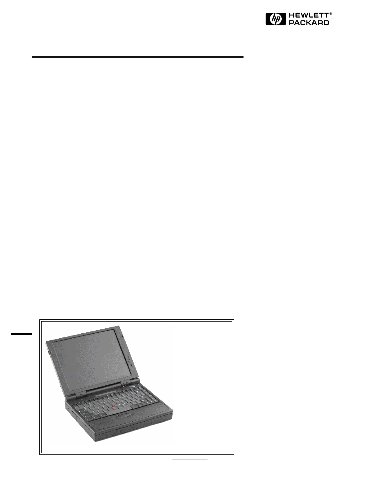
HP OmniBook 5500CS/CT
Familiarization Guide
This guide is for experienced HP Response Center
personnel, CEs, and reseller technicians. That is,
personnel that have already completed the HP Vectra
PC family training course, or equivalent, and have at
least six months of experience servicing the HP Vectra
PCs.
It is a self-paced training guide designed to train you to
install configure, and repair the OmniBook Notebook
PC. You can follow it without having any equipment
available.
Microsoft, MS, and MS-DOS are registered trademarks
and Windows is a trademark of Microsoft Corporation.
LapLink Remote Access is a trademark of Traveling
Software, Inc. System Soft is a registered trademark
and CardView, CardSoft, and CardID are trademarks
of SystemSoft Corporation.
Click on this frame to insert a graphic in this area.
1
Page 2

Table of Contectnsontents
43
39
38
37
36
35
28
28
27
26
24
24
OmniBook Product Comparisons .......................................................................
OmniBook 5500 Series: Product Features ...........................................................
Notebook Hardware Structure ...........................................................................
Removing LCD Assy and Icon Assy ......................................................................
Replacing Disp Panel Plastic, Disp Cover Plastic, Hook, and Hook Button .................
Removal and replacement of Rubber Feet, Plastic Feet, HDD Door, Memory Cover
Door, and RAM Expansion Module. ......................................................................
Removal of HDD Drive, FDD Module, CD-ROM Assy, Enhanced Li-Ion Battery,
Standard Li-Ion Battery, Printer Port Door, Expansion Door, and I/O door ...............
Removal of Palmrest Assy and Sub Battery Set (4.8V) .............................................
Removal of Keyboard and Power Supply Board (PCA PT-DC) .................................
Removal of Upper Chassis Case and Icon PCA (PCA PT-ICON) .............................
Removal of the Heat Pipe Bracket, Heat Pipe, Heat Pipe Spreader, CPU Module, and
Heat Sink ............................................................................................................
Removal of KBD Shielding Plate ...........................................................................
Removal of Motherboard (PCA PT-586 with I/O Bracket), HDD PCB Bracket,
HDD-FPC Flex, FFC Cable T/B to M/B 10 Pin, Bezel, IR Lens, and PCMCIA
buttons. ..............................................................................................................
Configuration and Setup ....................................................................................
Main Configuration Screen ...................................................................................
Power Screen ......................................................................................................
Power Configuration ............................................................................................
System Configuration ...........................................................................................
Input/Output Configuration ...................................................................................
Disk Configuration ...............................................................................................
Troubleshooting and Repair ...............................................................................
Final Quiz ..........................................................................................................
...........
...........
.........
.........
.........
.........
.........
.........
.........
.........
.........
.........
.........
.........
.........
.........
.........
.........
.........
.........
.........
.........
3
7
21
21
30
31
32
33
33
34
2
Page 3

OmniBook
Product Comparisons
256 colors)
cache
processor
processor
(
7.2 lb)
(11.6 x 8.9 x 1.93 in)
(11.6 x 8.9 x 1.93 in)
(11.6 x 8.8 x 2.05 in)
Size Closed
•29.5 x 22.5 x 5.2 cm
•29.5 x 22.6 x 4.9 cm
HP OmniBook 4000HP OmniBook 5000HP OmniBook 5500
v29.5 x 22.6 x 4.9 cm
Weight
Processor
Bus Architecture
Cache
Display
•100-, 120-, and
133-MHz Intel Pentium
256-KB external L2
cache
•10.4 and 12.1 - inch
diagonal TFT:
• SVGA (CTS): 800 x
600 x 64K colors
(TFT)
11.3 - inch diagonal
DSTN:
SVGA: 800 X 600 X
256 colors
•PCI local bus video;
1-MB video RAM
vSVGA-out supports
VGA & SVGA monitors
(up to 1024 x 768 x
•3.08-3.18 kg (6.8-7 lb)•3.4 kg (7.5 lb)
•75-, 90-, or 120-MHz
Intel Pentium
256-KB external L2
•10.4-inch diagonal:
•VGA (C/CT): 640 x
480 x 65,536 colors
(DSTN or TFT)
•SVGA (CTS): 800 x
600 x 256 colors
(TFT)
•PCI local bus video;
1.5-MB video RAM
vSVGA-out supports
VGA & SVGA monitors
(up to 1024 x 768 x
256 colors)
vDSTN (C): 3.13 kg
(6.9 lb)
vTFT (CT): 3.27 kg
v50-, 75-, or 100-MHz
Intel 486DX2
ISA bus32-bit PCI bus32-bit PCI bus
No L2 cachesome models include:
v10.3-diagonal DSTN
(up to 256 colors) or
v10.4-inch diagonal
TFT (up to 65,536
colors)
vVGA: 640 x 480
vLocal bus video;
1-MB display RAM
vSVGA-out supports
VGA & SVGA monitors
(up to 1024 x 768 x
256 colors)
3
Page 4

built-in speakers
built-in speakers
RAM cards
RAM cards
instantly
Power
•14.4Vdc
Rechargeable
Lithium-Ion battery
•Battery life
(approximate with one
battery LiIon): 2 to 3
hrs
•Battery (LiIon)
recharges to high level
in 4 hrs using AC
adapter while PC is on
or off
•2-minute low-battery
warning
•AC adapter 100 to
240 Vac (50 to 60 Hz)
input; 12 Vdc, 3.3 A
output
•Instant-on maintains
computer in
ready-to-work state for
weeks on a full charge;
returns you to your
application or file
•14.4Vdc
Rechargeable
Lithium-Ion or NiMH
battery
•Battery life
(approximate with one
battery): 2 to 3 hrs
•Battery recharges to
high level in 4 hrs
using AC adapter while
PC is on or off
•2-minute low-battery
warning
•AC adapter 100 to
240 Vac (50 to 60 Hz)
input; 12 Vdc, 3.3 A
output
•Instant-on maintains
computer in
ready-to-work state for
weeks on a full charge;
returns you to your
application or file
instantly
HP OmniBook 4000HP OmniBook 5000HP OmniBook 5500
v14.4 Vdc
rechargeable NiMH
battery pack
vBattery life
(approximate):
3-4 hrs on DSTN
DX2/50
2-3 hrs on TFT
DX4/100
vAC adapter 100 to
240 Vac (50 to 60 Hz)
input; 21 Vdc,1.35 A
output
Suspend-resume
power management.
Removable Modules
Mass Storage
RAM
Audio
•Floppy disk drive
internal/external (can
be replaced with a
second battery CD
ROM drive)
•Hard disk drive
•RAM
•Standard Battery
•810-MB, 1.35-GB,
2.0GB hard disks
v8 or 16-MB Models
•upgradable to 64 MB
•8-, 16-, or 32-MB
•16-bit with Sound
Blaster Pro compatible
and MIDI support
•Stereo sound via two
•Floppy disk drive (can
be replaced with a
second battery for
double battery life)
•Hard disk drive
•RAM
•Battery
•540-MB, 810-MB, or
1.2-GB hard disks
v8- or 16-MB Models
•upgradable to 64 MB
•8-, 16-, or 32-MB
•16-bit with Sound
Blaster and MIDI
support
•Stereo sound via two
vFloppy disk drive
(can be replaced with
a second battery for
double battery life)
vHard disk drive
vRAM
vBattery
v260-, 340-, 520-, or
810-MB hard disk
options
v4-, 8-MB, or 16-MB
RAM models
vupgradable to 32 MB
v16-bit, Sound
Blaster-compatible
vStereo sound via two
built-in stereo speakers
4
Page 5

and audio
.
and audio.
•MIDI/joystick
port
Input/Output
•9-pin, 115,200 - b/s,
RS-232 port
•9-pin, 115,200 - b/s,
RS-232 port
HP OmniBook 4000HP OmniBook 5000HP OmniBook 5500
v9-pin, 115,200 - b/s,
RS-232 port
Expandability
•25-pin EPP and ECP
parallel port
•SVGA-out (up to 1024
x 768 x 256); VGA-out
(640 x 480 x 16M
colors)
• Fast-IR-IRDA
compliant @ 4Mbps
•Expansion bus
connector
•NTSC/PAL video-out
port (RCA and SVideo)
•Keyboard/mouse port
•Headphone/stereo-out
port
•Stereo-in and
microphone ports
•MIDI/joystick port
•One Type III PCMCIA
slot (or use as two
Type II slots) with
3.3-V or 5-V support
vOptional docking
system with two
ISA-based slots, or
one ISA and one PCI
slot, parallel, serial,
SVGA-out (up to 1024
x 768 x 256),
keyboard, PS/2
mouse, MIDI/joystick,
•25-pin EPP and ECP
parallel port
•SVGA-out (up to 1024
x 768 x 256); VGA-out
(640 x 480 x 65,536
colors)
•115,200-baud,
bidirectional infrared
•Expansion bus
connector
•SCSI-2 port
•NTSC/PAL video-out
port
•Keyboard/mouse port
•Headphone/stereo-out
port
•Stereo-in and
microphone ports
•One Type III PCMCIA
slot (or use as two
Type II slots) with
3.3-V or 5-V support
vOptional docking
system with two
ISA-based slots, or
one ISA and one PCI
slot, parallel, serial,
SVGA-out (up to 1024
x 768 x 256),
keyboard, PS/2
mouse, MIDI/joystick,
v25-pin EPP and ECP
parallel port
vSVGA-out (up to
1024 x 768 x 256)
v115,200 - baud,
bi-directional infrared
vExpansion bus
connector
vKeyboard/mouse port
v
Headphone/stereo-out
port
vMicrophone port
vStereo-in port
vOne Type III
PCMCIA slot (or use
as two Type II slots)
vEnhanced port
replicator with parallel,
two serial, SVGA-out
(up to 1024 x768),
keyboard, PS/2
mouse, and SCSI
ports; and PCMCIA
slot (concurrent Type II
and Type III)
5
Page 6

•
Kensington
lock slots
Pre-installed Software
•Microsoft Windows 95
•Microsoft Windows 95
HP OmniBook 4000HP OmniBook 5000HP OmniBook 5500
vMicrosoft Windows
for Workgroups 3.11
Security Features
or
vMicrosoft Windows
for Workgroups 3.11 *
•MS-DOS 6.22
•Plug and Play BIOS
•HP PIM
• 2-level password
protection
• PC ID (tattooing) and
serialization
• Drive lock
or
vMicrosoft Windows
for Workgroups 3.11 *
•MS-DOS 6.22
•Plug and Play BIOS
•HP PIM
•2-level password
protection
•PC ID (tattooing)
•Kensington lock slots
vMS-DOS 6.2
vLaplink Remote
Access™
vEasy connection to
your desktop PC,
network and desktop
printers; works via
cable or infrared.
vUser password
vKensington lock slots
6
Page 7

OmniBook 5500 Series: Product Features
models and options.
who need
Pentium
desktop-to-go performance.
One year warranty.
One year warranty.
One year warranty.
One year warranty.
One year warranty.
One year warranty.
One year warranty.
Three year warranty.
Three year warranty.
Three year warranty.
Description
Models
HP OmniBook 5500 notebook PCs feature industry leading performance with the
powerful combination of Pentium processors and a true PCI bus for professionals
This is a complete list of all the standard OmniBook 5500 models now available.
Factory special options are not included in this listing. New models will continue to
be introduced.
Please refer to the Hewlett-Packard Corporate Price List for currently available
HP Part #DescriptionProduct
HP OmniBook 5500CT
LiIon Battery, 12.1" SVGA TFT Display,
HP OmniBook 5500CT
LiIon Battery, 12.1" SVGA TFT Display,
HP OmniBook 5500CT
LiIon Battery, 12.1" SVGA TFT Display,
HP OmniBook 5500CT
LiIon Battery, 10.4" SVGA TFT Display,
HP OmniBook 5500CT
LiIon Battery, 10.4" SVGA TFT Display,
HP OmniBook 5500CS
LiIon Battery, 11.3" SVGA DSTN Display,
F1320AP-133, PCI BUS, 2.0GB HDD, 16MB RAM,
F1321AP-133, PCI BUS, 1.35GB HDD, 16MB RAM,
F1322AP-120, PCI BUS, 1.35GB HDD, 16MB RAM,
F1323AP-120, PCI BUS, 1.35GB HDD, 16MB RAM,
F1324AP-120, PCI BUS, 1.35GB HDD, 16MB RAM,
F1325AP-120, PCI BUS, 1.35GB HDD, 16MB RAM,
HP OmniBook 5500CS
HP OmniBook 5500CS
HP OmniBook 5500CT
HP OmniBook 5500CT
F1326AP-100, PCI BUS, 1.35GB HDD, 16MB RAM,
LiIon Battery, 11.3 " SVGA DSTN Display,
F1327AP-100, PCI BUS, 1.35GB HDD, 8MB RAM,
LiIon Battery, 11.3" SVGA DSTN Display,
F1328AP-100, PCI BUS, 810MB HDD, 8MB RAM,
LiIon Battery, 10.4" SVGA TFT Display,
F1329AP-100, PCI BUS, 810MB HDD, 8MB RAM,
LiIon Battery, 11.3" SVGA DSTN Display,
7
Page 8

SVGA-out, keyboard, PS/2 mouse, audio, MIDI/Joystick, SCSI-2 ports,
dock. Docking system only for the
OmniBook
5000
F1064A
Automobile Adapter
F1338A
External Battery Charger (Charges up to two batteries concurrently)
F1194A
Enhanced
LiIon
Battery Pack Module
F1193A
Standard
LiIon
Battery Pack Module
F1073A
NiMH
Battery Pack Module
F1044B
AC Adapter
F1319A
Quad-speed CD-ROM drive
F1195A
3.5 inch Internal/External Floppy Drive Module
F1192A
1.35 GB Hard Disk Drive
F1191A
810-MB Hard Disk Drive
F1136A
32-MB RAM expansion card
F1135A
16-MB RAM expansion card
F1134A
8-MB RAM expansion card
battery.
supports PnP and hot docking. Motorized docking to ensure solid
Part # DescriptionAccessories
F1189ADocking system. Includes 2 full-length ISA slots, parallel, serial,
OmniBook 5500
enhancements over
the OmniBook
5000.
What comes in the
box
w 133MHz Pentium CPU
w Internal CD ROM Option - 4X Toshiba or Teac drive
w Internal floppy drive can also be used externally using built in cable
w IBM Tracpoint III pointing device replaces the track ball.
w Chips and Technologies Inc. (65548) from the 65545 PCI bus VGA Controller with
1 MB of display RAM
w SVideo Output Port
w Larger display options (12.1" TFT SVGA and 11.3" STN SVGA)
w VLSI 82C147 fastIR controller and HP-OED FastIR optical module.
w Second battery is a "super" battery and has 150% of the capacity of the standard
w OmniBook 5500 mainframe
w Battery pack
w Recovery CD ROM
w AC adapter (P//N: F1044B), localized power cord
w User documentation: Quick Start Guide, support documentation,
registration form
w Brochures for OmniBook accessories and Deskjet 320
Microprocessor
w Intel Pentium, 100 MHz w/16K internal cache and 256K L2 synchronous burst
cache
8
Page 9

w
6-3-3-3 burst hit, self refreshed
Bus Architecture
64MB
32MB
32MB
48MB
32MB
16MB
32MB
16MB
16MB
24MB
8MB
16MB
16MB
--
16MB
40MB
32MB
8MB
24MB
16MB
8MB
16MB
8MB
8MB
8MB
--
8MB
Configurations:
looked at as possible
second sources.)
(read)
Resistive)
Resistive)
Resistive)
likelihood)
likelihood)
likelihood)
ATA2
Interface
ATA2
Interface
ATA2
Interface
Memory and Memory
Slots
w Intel Pentium, 120 MHz w/16K internal cache and 256K L2 synchronous burst
cache
w Intel Pentium, 133 MHz w/16K internal cache and 256K L2 synchronous burst
cache
PCI (Peripheral Component Interconnect)
w 0MB on Board
w Max Possible RAM: 64MB
w Type of memory boards: HP Proprietary Daughter boards, 2 user
accessible slots on the bottom case.
w Expansion Memory Board Options:
8-MB RAM, p/n: F1134A
16-MB RAM, p/n: F1135A
32-MB RAM, p/n: F1136A
w RAM Manufacturer: Multiple Vendors: NEC, Samsung, etc.
w Cycle time: 70 ns
Total RAMMemory Slot 2Memory Slot 1Possible Memory
Mass storage
The hard disk drive can be removed by the user for easy upgrades.
The hard drive is located on the bottom case and with the removal of
one screw the hard drive can be replaced.
w Hard drive manufacturer: Toshiba (Subject to change. IBM and Maxtor are being
2.0GB 1,350MB 810 MB2.5" Hard
Drive
Recording
Method
Heads
PRML (Partial
Response
Maximum
MR (Magneto
PRML (Partial
Response
Maximum
MR (Magneto
PRML (Partial
Response
Maximum
MR (Magneto
13 ms 13 ms 13 ms Average seek
9
Page 10

532
Disks
1064
Data Heads
k at zone 0
Cylinders
Zones
512 Bytes
512 Bytes
512 Bytes
Sector Size
Configuration:
transfer
transfer
transfer
le errors
Hours
Reliability:
time
buffer)
buffer)
16.6Mbytes/sec
16.6Mbytes/sec
16.6Mbytes/sec
Buffer to host
Mbits/sec
speed
latency
25 ms
25 ms
25 ms
Full Track
seek
Drive
2.0GB 1,350MB 810 MB2.5" Hard
3 ms3 ms3 msTrack to track
6.1 ms6.1 ms6.1 msAverage
4200 rev/m4200 rev/m4200 rev/mRotational
Media Transfer
rate
Buffer size
Power-on
Unrecoverab
sectors/Trac
38 (inner), 56.0
(Outer) Mbits/sec
64KB (read and
write segmented
1.0E-14 bits
38 (inner), 56.0
(Outer)
64KB (read and
write segmented
1.0E-14 bits
88Recording
38 (inner), 56.0
(Outer) Mbits/sec
3 sec3 sec3 secSpindle start
300,000 hours300,000 hours300,000 hoursMTBF:
1.0E-14 bits
3,6603,6603,660User
135135135User
Note: The hard disk drive can be removed by the user for easy
upgrades. The hard drive is located on the bottom case and with the
removal of one screw the hard drive can be removed.
10
Page 11

Center Bay Modules
w Floppy Disk Drive:
Internal 3.5 inch, 1.44-MB flexible disk drive is standard on all
models. The flexible disk drive can be easily removed by the user
and replaced with an additional battery pack to double battery life or
with CD ROM Module. The Floppy Disk Drive Modeul has a built in
cable that allows the module to be used externally (through the
parallel port) as well. This allows the Floppy Disk Drive and the CD
ROM to be used at simultaneously.
Manufacturer: Teac
w CD ROM
Internal 4X CD ROM, IDE (ATAPI standard). Unlike the Floppy
Disk Drive Module, the CD ROM Module can not be used
externally.
Manufacturer: Toshiba
Specs:
Transfer Rate: 600K sustained (Burst 8.ssMB/s - Mode3)
Buffer: 128K
Access: 200ms
Built-in I/O
Seek: 170ms
Modes: CDROM (Mode 1&2), Photo CD, CD Plus, CDXA, CD-I,
Multisession
w LiIon Battery Module
The large LiIon Battery Module has 150% of the capacity of the
standard LiIon battery. It installs in the center bay. This module is
approved as a component by UL, CSA, and TUV.
w 9-pin, 115,000-b/s RS-232 port, UART 16550
w 25 pin bi-directional ECP, EPP, and external FDD autosense parallel
port
w SVGA out (up to 1024 x 768 x 256 colors) with simultaneous viewing
VGA out (640 x 480 x 16M colors)
w Fast-IR-IRDA compliant @ 4 Mbps
w Expansion Bus Connector for connecting to the docking station
(includes PCI, AT bus and multimedia signals.
w 2 NTSC/PAL ports: 1 RCA, 1 S-Video
w Keyboard/mouse port
w Headphone/stereo-out port
w Microphone port
w Stereo-in port
11
Page 12

w MIDI/joystick port
EDO
EDO
EDO
RAM
bit)
bit)
diagonal
diagonal
75HZ
256
1024 x 768
60Hz
64K
1024 X 768
75Hz
256
800 X 600
60Hz
64K
800 x 600
75HZ
64K
640 X 480
60Hz
16M
640 x 480
Refresh
Maximum colors
Resolution
1. The unit should be viewed in the customer's normal operating condition.
complaint of cosmetic imperfection in their
TFT
display:
to the display manufacturers cosmetic quality specifications.
free of cosmetic imperfections.
is not specific to the HP
OmniBook
display.
conditions and can appear as bright, dim or dark spots.
Display/Video
TFT SVGA
Display
Active Matrix
800 x 600 x 64K
colors @ 60HZ
(18 bit)
Twisted Nematic
11.3 inches diagonal12.1 inches
640 x 480, 256 or
64K colors @ 60Hz.
Refresh: 160ms (8
Size
Resolution
TFT SVGA
Display
Active Matrix
10.4 inches
800 x 600 x 64K
colors @ 60HZ
Refresh: 90ms (18
32-bit PCI bus 32-bit PCI bus32-bit PCI busVideo bus, display
Memory
1-MB display RAM
1-MB display RAM
1-MB display RAM
w Display Manufacturer: Hitachi
w Video graphics controller chip: Chips and Technologies CT 65548
w External video resolution (both types): Supports VGA/SVGA
external monitors with up to 1024 x 768 x 256 colors in noninterlaced
mode. Resolution options:
DSTN Display
Dual Scan
Display/Video
TFT Display Quality
w DSTN Displays do not support panning modes for 1024 X 768
external and 800 X 600 internal.
w Auto detection of external monitor without rebooting
Note: Includes option to simultaneously display external video and
notebook display.
TFT display manufacturing is a high precision but imperfect technology and
manufacturers cannot currently produce large displays that are cosmetically perfect.
Most if not all TFT displays will exhibit some level of cosmetic imperfection. These
cosmetic imperfections may be visible to the customer under varying display
This issue is common across all vendors supplying TFT displays in their products and
The HP OmniBook TFT displays meet or exceed all TFT manufacturer's standards
for cosmetic quality of TFT displays. HP does not warrant that the displays will be
TFT displays may have a small number of cosmetic imperfections and still conform
Here are some guidelines to use in determining what action to take on a customer
12
Page 13

guidelines as the improvements are implemented.
should consider switching to an
OmniBook
with a
DSTN
display.
customer to use a
work-around
to obscure the cosmetic imperfection.
a defect in material or workmanship based on the HP Limited Warranty Statement.
replacement.
replacement.
2. In the customer's normal operating mode:
This means if the customer uses the unit predominately in DOS, or Windows, or in
a sufficient tool to interpret display quality.
10 days
2 - 3
hrs
Standard
LiIon
some other application or combination of applications, that is where the
determination shall be made. Self test is not a normal operating condition and is not
a. If 4 or more variant pixels appear clustered in the area approximated by a
thumbprint on the display surface, then the display should be considered for
b. On OmniBook 4000CT models, if more than 30 total pixels anywhere on the
display are bad, then the display should be considered for replacement. On
OmniBook 600CT and OmniBook 5000CT/5500CT models, if more than 15 total
pixels anywhere on the display are bad, then the display should be considered for
These are the only conditions in this guideline that may call for a replacement due to
3. If a display is considered for replacement, it should be clear to the customer that
cosmetic variations on the replacement display may also exist, and may require the
TFT Display Quality
(continued)
User interface
Power
4. Customers with cosmetic-based complaints only, that do not conform to the above
conditions and tests will not normally be considered for display replacement. It will
be left to the judgment of the HP-responsible person who, in working with the
customer, to identify work-arounds that are reasonable and appropriate for the
individual customer. Customers who must have a more perfect display solution
We expect over time that the industry will continue to improve in their ability to
produce displays with fewer inherent cosmetic imperfections and will adjust our HP
wKeyboard: 85/86-key touch-type keyboard with embedded numeric
keypad and 12 Fn keys. Wrist pad provides comfort for extended
keyboard use. External 6-pin mini-DIN interface for external keyboard
and/or mouse connection. OmniBook 5500 supports the Y connector to
use both the keyboard and mouse. (HP external keyboard (101-key)
Part number C3756A)
w Pointing device: IBM Trackpoint III in GBH position.
w Optional pointing devices: Includes 6-pin mini-DIN interface for
external PS/2 mouse connection. Also supports serial mouse
connection.
w Standard Battery types: Removable 14.4-Vdc rechargeable NiMH
and Lithium Ion battery. Both battery types do not require complete
discharge before recharging. There is no "memory" effect that
reduces battery life.
w Large Battery types: Removable 14.4-Vdc rechargeable NiMH and
Lithium Ion battery. Both battery types do not require complete
discharge before recharging. There is no "memory" effect that
reduces battery life.
w The OmniBook 5500 batteries are not compatible with previous
OmniBooks (5000 or 4000).
data (approx.):
13
Suspend to RAMRun ModeBattery TypeBattery Life; rundown
Page 14

14 days
3 - 5
hrs
Large
LiIon
data (approx.):
w
HP part number: HP #
F1338A
storage.
power to ports and the CPU.
Power
Suspend to RAMRun ModeBattery TypeBattery Life; rundown
w Recharge time (Display off): 4hrs (Standard Li-Ion), 5hs (Lrge
Li-Ion)
w Recharge time (Display on): 5.3hrs (Standard Li-Ion), 6.7 hrs (Large
Li-Ion)
Note: If unit has 1 standard LiIon and 1 large LiIon: 4 hrs +5 hrs = 9
hrs.
w Low battery signals: 2-minute low battery warning. Unit will shut
down if battery warning ignored to ensure data retention.
w Instant on: Maintains OmniBook in ready-to-work state for days or
weeks on a full charge; when turned on it returns instantly to previous
state. No waiting for restoring from disk. Accomplished by the use of
self refreshed DRAM technology. Note: The OmniBook 5500 utilizes
the same technology as the OmniBook 5000 and 600 to achieve the
instant on feature.
w Smart Battery: The OmniBook 5500 uses "Smart" battery
technology. The battery itself contains an ASIC (Application Specific
Integrated Circuit) that is able to continuously test and track the status
of the battery. The OmniBook BIOS can then receive high-quality
information about the battery condition directly from the hardware and
not interrupt the CPU. The condition can be checked using two
methods that receive information from the BIOS (CONFIGURATION
[fn][f2], Windows Control Panel Power).
w Energy S.T.A.R. compliant
External battery
charger
Automobile adapter
Standard LiIon
battery pack
w AC Adapter: 100 to 240 Vac adapter (50 to 60 Hz) input; 12 Vdc, 2.5
A output. Same adapter as the OB600 (F1044B). Use only an HP
F1044B AC adapter (the type shipped with the OmniBook). Using any
other adapter could damage the OmniBook and void the warranty.
Always plug it into a grounded outlet.
w Power management options: Advanced; Standard; Off; Custom.
w The OmniBook 5500 includes a "fake" off mode while docked. This enables the
user to turn off the OB5500 while docked and not loose any connectivity (such as to
a network). Basically, this mode shuts down the display only and maintains all
wA fully charged NiMH battery in storage will loose 20% of its charge per month in
w Designed for desktop use. Powered by the F1044B adapter
w Charges two additional batteries
w Size: 15.5 x 13.3 x 5.2 cm (estimated), no weight estimate at this date
HP # F1064 - same as OmniBook 600 and 5000
HP # F1193A
14
Page 15

w
90% relative humidity at 149 degrees F (65 degrees C) maximum
w
speakers using as these can be a factor in the distortion created.
w
w
w
w
Supports Native Signal Processing
(NSP)
and is Plug and Play compatible.
Enhanced LiIon
battery pack
Extra AC adapter
Accessory Slots
Audio Systems
HP # F1194A
HP # F1044B
w User available PCMCIA Slots: 2 Type II or 1 Type III
w Bus: Intel QuickSwap (ExCa)
w The PCMCIA slots are fully industry compatible and supports the
latest SystemSoft Card Services and Socket Services. The system
will support a wide variety of PCMCIA cards.
w PCMCIA controller chip manufacturer: Cirrus Logic (CL-PD6729).
Note: This is fully compatible with the Intel 365 chip). Cirrus Logic is
the original company that developed the PCMCIA controller and is
considered the best in the industry.
w High performance audio: 16-bit stereo sound, Sound Blaster hardware compatible.
Two stereo speakers with acoustic chambers
I/O: Headphone/stereo-out port; microphone port; Stereo-in port
IRQ default setting for soundblaster is 5.
Audio controller and Manufacturer: CS4232, Crystal
w Audio controller characteristics:
Operating
environment
Storage environment
Environmental
Testing
sampling: 8-48kzh
playback rate: 8-48kzh
distortion: maximum is 0.02% although you need to consider the type of external
w Temperature: 0 to 35o C (32 to 95o)
DSTN display models: 41 to 104 degrees F (5 to 40 degrees C)
TFT display models: 50 to 104 degrees F (10 to 40 degrees C)
90% relative humidity at 104 degrees F (40 degrees C) maximum
w Temperature: -40 to 149 degrees F (-40 to 65 degrees C)
w ESD as per IEC-801-2, EN 55024-2
w Drop testing: 225g, 3ms half sine wave shock: 6 axis, 3 hits per
side.
w Also tests for altitude, magnetic & radiated susceptibility &
interference, shock & vibration.
Note: These are the tests that HP designs notebook computers to
meet. Due to normal variations in the components of individual
machines, some machines will perform better and some won't perform
as well. HP does not garantee that every notebook computer will meet
these specifications.
15
Page 16

w
2 - level password protection
(admin
and user levels), PC ID (tattooing)
* Supported to the application level.
**
Only setup and configuration supported.
w
MS-DOS 6.2
update process.
BIOS
ww Plug and Play BIOS stored in EEPROM
ww User Upgradable via floppy drive
ww A corrupt BIOS that prevents the machine from booting requires a Motherboard
replacement. The BIOS can be corrupted by interrupting a BIOS upgrade during the
Software and
Operating System
Supported Operating
Systems
Security
ww Microsoft Windows for Workgroups 3.11 or Windows 95
The HP OmniBook 5000/5500 family comes co-loaded with Windows for Work
Groups and Windows 95. The user selects the operating system of choice
and the other is auto deleted.
wMS DOS version 6.22*
wMicrosoft Windows for Workgroups 3.11*
wMicrosoft Windows 95*
wMicrosoft NT workstation 3.51**
wOS/2 version 3.0**
w Physical security from Kensington Lock
16
Page 17

and opening a unit.
appropriate keys by mistake, pressing [ESC] will allow entering the stored password.)
Password Decode
If the user forgets the system password, there is a master password that will unlock
the OmniBook. The user calls Technical Support to determine this master password
as follows:
1. Support will tell the user the keys to type at the password entry screen ?
2. The OmniBook generates and displays an encoded master password. This is
displayed under the normal password entry area. At this point, this is the only
password that will unlock the OmniBook unless the user presses [ESC] to remove the
encoded master from the password entry screen. Then the user's stored password
can be entered.
3. The user reads the encoded master password to Support.
4. Support runs a program that decodes the encoded password, and reads the
decoded password (alphanumeric) to the user.
5. The user types in the decoded password.
6. OmniBook decodes the encoded master password it generated and compares it to
the decoded password typed in by the user.
7. If the two passwords match, the OmniBook is unlocked. The forgotten password is
automatically erased. Support can then guide the user through the process of
entering a new password.
8. If the two passwords do not match, the previous sequence must be repeated until
the user correctly enters a master password.
The encoded master password is an eight-character alphanumeric sequence that the
OmniBook generates at random every time the appropriate keys are pressed in the
password entry screen. Because it is generated randomly, a master password can
only be used to unlock the OmniBook once. If the user forgets the password at
another time, it will require another call to Support. (If the user presses the
Password Decode
Policy
The password descramble programs for the HP OmniBook PCs are protected as HP
Company Private information. They may not be copied, backed-up, printed or
distributed. There are only six official copies of each program.
In addition to protecting the program itself, it's use is also controlled.
Hewlett-Packard and authorized support providers must ensure with written evidence
that the OmniBook that is being "descrambled" is actually in the hands of the unit's
actual and current owner. This requires a sales receipt showing the unit serial
number and owner's name, or a written statement from the owner attesting that they
are the owner of the unit. The statement can be a FAX copy of the document. The
fact that the unit is in the hands of an HP representative on the behalf of the
customer is not evidence of ownership. In addition, HP will not descramble a unit for
any non-owner, even if it involves law enforcement agencies. If you receive such a
request, you should notify management and HP Corporate Legal immediately.
(These requests may require a court order prior to our participation.)
Further, you must log the name, serial number and date of the running of the
descramble program, and file the written backup with the log. The log and backup is
subject to standard record's retention process and review.
The final issue relating to descramble of passwords is that HP cannot provide
information to users that would assist them in improperly descrambling a password
17
Page 18

Notebook Hardware Structure
The following guidelines apply to all subassembly level repairs
w Properly ground yourself and your work area to prevent damage from static discharge
w Always replace any conductive sponge material or thermal tape that becomes damaged during repairs.
w Use a #0 Phillips screwdriver to remove all screws
Field Replaceable Assemblies
Removing LCD Assy and Icon Assy (Hewlett-Packard Authorized Service Providers Only)
The LCD Assy and/or Icon Assy on the OmniBook 5500CS and CT are removed the same way as on the OmniBook 5000. Turn the unit over,
raise the feet, and withdraw the two Phillips screws (screw - display) from under the feet in the bottom back corners of the unit (see diagram
below which shows the OmniBook 5000).
18
Page 19

Turn the unit right side up and dislodge the Icon Assy by placing the thumbs on each edge of the Assy and pushing lightly (see diagram below
which also shows the OmniBook 5000). The front edge of the Icon Assy will lift up slightly.
19
Page 20

Lift the LCD Assy straight up about 1 inch. The Icon Assy will lift up with the display. Move the Icon Assy out of the way. The cable from the
Icon Assy to the PCA PT-ICON does not need to be removed if only the LCD Assy is being removed. Otherwise, slide the connector sleeve up to
remove the Icon Assy cable.
If only the Icon Assy is to be removed, the LCD Assy may be lowered back into position.
To remove the LCD Assy, remove the two cables attaching the LCD Assy to the PCA PT-ICON . Lastly, remove the two screws attaching the
grounding straps to the PCA PT-ICON. The LCD Assy can now be removed the rest of the way.
Notice that the display cabling assembly on the OmniBook 5500 is different than on the OmniBook 5000. The LCD Assy is not transferable
between the two models.
To reinstall the LCD Assy or Icon Assy, just reverse the above procedure. When reinstalling the LCD Assy, make sure that the two posts on
either side of the Assy line up parallel with their slots in the top case. If they are not parallel, the post will get caught inside the top case
before the display is seated completely. If this happens, remove the display and line the posts up properly.
20
Page 21

Replacing Disp Panel Plastic, Disp Cover Plastic, Hook, and Hook Button
Remove four rubber 'feet' from the inside of the LCD Assy. Remove four Phillips screws from under the rubber 'feet". Remove the contrast and
brightness control knobs (TFT displays only have on knob). Firmly pull panel apart as shown in the diagram below. Display panel plastic can
now be replaced.
To replace hook, first remove spring. Then remove outer button by compressing tabs on inside of hook and prying button out. Hook can now
be removed.
To replace Disp Cover plastic, remove LCD Panel, both LCD PCBs, clutch assemblies, and hooks. Replace these items in the new Disp Cover.
21
Page 22

Removal and replacement of Rubber Feet, Plastic Feet, HDD Door, Memory Cover Door, and RAM
Expansion Module.
Rubber feet are secured to the Lower Chassis Case with adhesive. To remove just pry off. To replace, use attached adhesive.
Plastic feet are removed by compressing the two plastic tabs in the hinge area and pulling the tab out. Reverse the procedure to replace.
The HDD security cover is secured by the one black Phillips Screw - HDD Door. Remove this screw to remove the door. This door must be
removed to remove the HDD Drive.
The Memory Cover Door can be removed by pulling up on the Door with a fingernail placed in the recess on the Lower Chassis Case.
Ram Expansion Modules are removed by pulling on the tabs next to the module. RAM Expansion Modules are end user replaceable.
22
Page 23

23
Page 24

Removal of HDD Drive, FDD Module, CD-ROM Assy, Enhanced Li-Ion Battery, Standard Li-Ion Battery,
Printer Port Door, Expansion Door, and I/O door
To remove HDD Drive, first remove the HDD Door (see instructions on previous page). Once HDD Door is removed, HDD Drive can be
withdrawn from the front of the machine. The HDD Drive is user replaceable.
To remove the FDD Module, CD-ROM Assy or the Enhanced Li-Ion Battery, slide the knurled level on the front of the module to be removed to
the right (when looking at the unit from the front). Pull straight out on the level that is released. The FDD Module, CD-ROM Assy and the
Enhanced Li-Ion Battery are user replaceable.
To remove the Printer Port Door, Expansion Door, or I/O Door, bow the door in the middle until the hinges on each edge clear the recess in
the Lower Chassis Assembly. Reverse
the procedure to install the doors.
24
Page 25

Removal of Palmrest Assy and Sub Battery Set (4.8V)
To remove the Palmrest Assy, first follow the instructions above to remove the HDD Drive, Center Bay Module (FDD Module, CD-ROM Assy, or
Enhanced Li-Ion Battery) and the Standard Li-Ion Battery. From the bottom of the unit, remove the four screws (Screw CPU M2.6 X 6L). Turn
unit right side up and place a thin flat instrument under the edge of the Palmrest Assy and pry up. The Palmrest Assy will snap up.
Lay the Palmrest Assy upside down on the keyboard. Slip the connector sleeves forward on the ribbon cable connectors on the underside of
the Palmrest and remove the ribbon cable. To remove the Sub Battery Set, remove the tape that holds the wires to the Upper Chassis case.
Next, remove the Sub Battery Set connector from the Palmrest Assy.
Reverse the procedure to reassemble.
25
Page 26

Removal of Keyboard and Power Supply Board (PCA PT-DC)
To remove the Keyboard and PCA PT-DC, first follow the instructions above to remove the HDD Drive, Center Bay Module (FDD Module,
CD-ROM Assy, or Enhanced Li-Ion Battery), Standard Li-Ion Battery, and the Palmrest Assy. Remove the four screws (Screw - Keyboard) from
the front edge of the keyboard. The keyboard then lifts up and rotates backward around the two ribbon cables that connect it to the PCA
PT-DC. Remove the PCA PT-DC by pulling up on the tabs on either side of the PCA PT-DC. Separate the Keyboard and the PCA PT-DC by
sliding the sleeves forward on the two ribbon cable connectors on the PCA PT-DC and withdrawing the cables.
Reverse the procedure reassemble.
26
Page 27

Removal of Upper Chassis Case and Icon PCA (PCA PT-ICON)
To remove the Upper Chassis Case and PCA PT-ICON, first follow the instructions above to remove the HDD Drive, Center Bay Module (FDD
Module, CD-ROM Assy, or Enhanced Li-Ion Battery), Standard Li-Ion Battery, Palmrest Assy, Keyboard and PCA PT-DC. Remove the one
screw (Screw - CPU M2 X 4L) on the left side of the Upper Chassis Case. Upper Chassis Case can then be snapped off. If necessary the
suspend/resume button assembly (PA PT-TRP), which comes with the Upper Chassis Case repair part, can be removed by removing the two
screws.
Remove the one screw (Screw - CPU M2 X 4L) holding the PCA PT-ICON down. Pull straight up on the PCA PT-ICON to remove it.
Reverse the procedure to reassemble. Make sure microphone fits in the recess in the Upper Chassis Case on reassembly.
27
Page 28

Removal of the Heat Pipe Bracket, Heat Pipe, Heat Pipe Spreader, CPU Module, and Heat Sink
To remove the Heat Pipe Bracket, Heat Pipe, Heat Pipe Spreader, CPU Module, and Heat Sink, first follow the instructions above to remove the
HDD Drive, Center Bay Module (FDD Module, CD-ROM Assy, or Enhanced Li-Ion Battery), Standard Li-Ion Battery, Palmrest Assy, Keyboard,
PCA PT-DC, Upper Chassis Case, and PCA PT-ICON. Remove the one screw (Screw - CPU M2 X 4L) from the Heat Pipe Bracket and remove the
two screws (Screw - CPU M2 X 4L) from the Heat Pipe Spreader. Now the Heat Pipe Bracket, Heat Pipe, and Heat Pipe Spreader can all be
removed.
Remove the four screws (Screw - CPU M2 X 4L) from the corners of the CPU Module. The three screws in the center of the module should not
be removed. Lift straight up on the CPU Module to remove.
To remove the Heat Sink, remove the two screws (Screw ISOT M2.6 X 4L) in the Heat Sink.
Reverse the
above
procedure
to
reassemble.
28
Page 29

Removal of KBD Shielding Plate
To remove the KBD Shielding Plate, first follow the instructions above to remove the HDD Drive, Center Bay Module (FDD Module, CD-ROM
Assy, or Enhanced Li-Ion Battery), Standard Li-Ion Battery, Palmrest Assy, Keyboard, PCA PT-DC, Upper Chassis Case, PCA PT-ICON Heat Pipe
Bracket, Heat Pipe, Heat Pipe Spreader, CPU Module, and Heat Sink.
Remove the five screws (Screw ISOT M2 X 6L) that hold the KBD Shielding Plate down.
Reverse the procedure to replace KBD Shielding Plate.
29
Page 30

Removal of Motherboard (PCA PT-586 with I/O Bracket), HDD PCB Bracket, HDD-FPC Flex, FFC Cable
T/B to M/B 10 Pin, Bezel, IR Lens, and PCMCIA buttons.
The PCMCIA buttons can be removed at any stage of the disassembly process. They must, however, be removed before removing the
motherboard.
To remove the Motherboard (PCA PT-586 with I/O Bracket), HDD PCB Bracket, HDD-FPC Flex, FFC Cable T/B to M/B 10 Pin, Bezel, IR Lens,
first follow the instructions above to remove the HDD Drive, Center Bay Module (FDD Module, CD-ROM Assy, or Enhanced Li-Ion Battery),
Standard Li-Ion Battery, Palmrest Assy, Keyboard, PCA PT-DC, Upper Chassis Case, PCA PT-ICON Heat Pipe Bracket, Heat Pipe, Heat Pipe
Spreader, CPU Module, Heat Sink and KBD Shielding Plate.
The HDD PCB Bracket, the HDD-FPC Flex, and the FFC Cable T/B to M/B 10 Pin can all be removed without removing the PCA PT-586. When
removing the HDD-FPC Flex be sure to pull straight up on the connector, sideways pressure can damage or break the connector pins requiring
a full motherboard replacement..
To Remove the Motherboard (PCA PT-586 with I/O Bracket), remove the three screws (two are ISOT M2 X 6L and one is an ISOT M2 X 4L) that
hold the PCA PT-586
in place. Remove the
two standoffs (notice
that one is 11.75mm
long and the other is
15mm long). Remove
the Dock Grounding
Spring Plate. Remove
the two PCMCIA
buttons. Make sure
that you have removed
all RAM expansion
modules. Then lift the
PCA straight up. The
I/O Bracket comes as
part of the PCA
PT-586. If only the I/O
Bracket is damaged, it
can be ordered
separately and
replaced by removing
the 4 standoffs and
two screws from the
back of the bracket.
30
Page 31

Configuration and Setup
Main Configuration Screen
Pressing [fn][f2] invokes the BIOS setup and configuration utility. The screens shown in this section of the familiarization guide are from the
OmniBook 5000. The OmniBook 5500 is the same except in the few cases noted in the text.
Users can check system configuration and change settings using [f] keys from this screen. This is the most accurate place to check battery
and system status. Pressing [f3] from this screen exits back to the current application. The setup/configuration utility is operating system
independent. The main screen also displays the BIOS revision in the upper bar.
31
Page 32

Power Screen
The power screen contains the current power level of the main and auxiliary battery. The auxiliary battery charge status does not show up if no
auxiliary battery is installed. Power conservation settings consists of the options shown which allow customer selection of "Turn OFF" (instant
off), "Auto Save-to-disk", "HDD power-down", and "CPU power-down".
32
Page 33

Power Configuration
To implement the power management capabilities, the following settings are set by the user from the power setup screen.
Comments:Default:Parameters:Setting:
Enables power saving
techniques.
How long the system will
stay in Run with (no
activity). If disabled it will
stay in Run.
How long the system will be
in off before the entire state
of the computer the
suspend state. If disabled
it will stay in the suspend
state.
HDD will turn off, system
has ability to run. HDD will
spin up when access
required.
CPU clock rate will be
reduce if the system has
been idle for the selected
delay. The clock rate will
be restored when system
activity is detected.
Turn OFF
Auto Save-to-disk
HDD power-down
OnOff/OnPower Saving
3 minutes Disable/Time
(1 - 30 minutes or never)
1 dayDisable/Time
(6 hours to 7 days or never)
3 minutesDisable/Time
(1-30 minutes or never)
2 sec512ms-8secondsCPU power-down
33
Page 34

System Configuration
The system screen contains the processor and memory information for the user to glance at. It also allows the user to set the date and time.
The real time clock is not changed until the user exits the setup program. The user can also enable or disable the processor cache.
When the user decides to enable a password, a pop up window requests the old password, new password and confirmation of the new
password. Hard drives or mass storage are not affected by the password--only the turn-on condition.
34
Page 35

Input/Output Configuration
COM Ports
LPT Port
LPT Type
Keyboard Setup
External Devices
Serial Port (None, COM1 - COM4)
and I/R Port ( None, COM1COM4)
278/ LPT3, Addr3BC
(Centronics)
Key Delay (1/4 - 1sec) and Key
Repeat Rate (2cps - 30csp)
VGA Display Device, Television
type
Comments:Default:Parameters:Setting:
Serial Port: COM1, Addr 3F8, IRQ 4
I/R Port: COM2, Addr 2F8, IRQ 3
LPT1, Addr 378None/LPT1, Addr 378/ LPT2, Addr
Bi-directionalBi-directional (PS-2)/Standard AT
Key Delay 1/2 sec, Key Repeat Rate
10CPS
VGA Display Device - external VGA if
attached, LCD off. Television type:
NTSC on option ABA units.
Audio volume: ? Beeper Volume: 3Audio volume, Beeper volumeAudio Ports
35
Page 36

Disk Configuration
Hard Disk Drive
Custom, Auto-ID
Comments:Default:Parameters:Setting:
1.44MBNone, 1.44MB, 2.88MBFloppy Disk Drive Diskette A
Auto-IDDisk Type: None, Standard,
Also reports disk drive data (#
cylinders, # heads, sectors/tracks,
landing zone, write precomp)
36
Page 37

Troubleshooting and Repair
returning the product for repair.
Known Hardware
Issues
OmniBook
Self-Test
w The OmniBook 5500 is the first OmniBook to incorporate drive lock. Drive lock
locks the IDE interface on the hard disk drive so that the drive can not be removed
from one OmniBook and read in another OmniBook. Both the IBM and Toshiba Hard
Disk Drives that ship with the OmniBook 5500 incorporate this feature.
Once a user sets the User Password in the SCU, the OmniBook automatically
transfers that password to the hard disk drive in the unit. If the hard disk drive is put
in another unit, the password of the new OmniBook must be changed to match the
password set on the drive in order to access the drive.
If the User Password does not match the drive lock password, a message will be
displayed warning that the drive could not be unlocked because of an incorrect
password. :
A drive failure will not display the drive lock error message.
If the unit still functions, insure that the user removes the user password before
w The complete self-test procedure is documented in the OmniBook 5500 Operating
Guide.
37
Page 38

w
w
w
w
CODES
First POST: BEEP
CODES
w A note about interpreting self-test results.
Self-test alone should not be used to diagnose a hardware problem. If the self-test
results are absolutely clear and repeatable, confirm the results with at least two other
non-self-test failure symptoms.
w The OmniBook 5500 BIOS includes a POST facility that tests a number of
hardware and firmware items in the unit at each cold-start (BOOT or RESET).
These multiple beep codes indicate a failure in a simple test of:First POST: BEEP
a portion of base memory
Flash BIOS checksum
a portion of conventional memory
a portion of extended memory
w If the unit fails to boot:
all accessories are removed, including memory cards, external floppy, port expander,
modems, PCMCIA cards, LAN cards, printers, VGA-out cables, external pointing
devices, clean AC power is provided (no "chained" battery chargers or auto
adapters), and press reset.
If the unit still fails to boot, it requires service.
w Beep codes
Beep codes are used to identify a POST error that occurs when the screen is not
available. Once the screen is operating, diagnostic messages are reported to the
screen. There are beep codes for both fatal and nonfatal system board errors.
38
Page 39

No RAM installed. No message is
dispalyed.
S-S-L-P-S-S-L-P
No video adapter was found
S-S-L-P-S-S-S-P
The 8042 keyboard controller failed
S-S-S-P-L-L-L-P
The interrupt controller failed
S-S-S-P-L-L-S-P
The DMA controller is faulty
S-S-S-P-L-S-L-P
The
CMOS
RAM test failed
S-S-S-P-L-S-S-P
The ROM checksum is incorrect
S-S-S-P-S-L-L-P
The refresh circuitry is faulty
S-S-S-P-S-L-S-P
The DMA page registers are faulty.
S-S-S-P-S-S-L-P
DescriptionBeep Code
Last POST:
DISPLAY CODES
wThere are a number of POST tests that are performed after the BEEP Code tests.
Failure of one or more of these tests will result in a displayed failure code (i.e.,
03044). It is extremely important not to interpret a failure code immediately as a
hardware failure until:
all accessories are removed, including memory cards external floppy, port expander,
modems, PCMCIA cards, LAN cards, printers, VGA-out cables, external pointing
devices, clean AC power is provided (no "chained" battery chargers or auto
adapters), and press reset.
If the unit still fails to boot, it requires service.
NOTE: make sure the display is adjusted to be visible.
39
Page 40

from these codes.
not available.
PhoenixBIOS POST
The periodic timer interrupt is not occurring
.
NO INTERRUPTS FROM TIMER
0
Replace the diskette drive if necessary.
you insert the key into the key lock and turn it.
Command.
the problem continues, replace the controller.
not match the installed hardware.
CARD - RUN
SCU
may need to replace the hard disk controller.
the floppy drives detected in the system.
persists, you may need to replace the floppy drive.
contines
to fail, you may need to replace it.
reinitialized via the System Configuration Utility.
Utility.
incorrect for the installed hardware.
The real time clock is not ticking.
CLOCK NOT TICKING CORRECTLY
Messages (Power
On Self Test
Within POST, there are three kinds of messages:
Error messages: These messages appear when there is a failure in hardware,
software, or firmware.
Informational messages: These messages provide information to the user but require
no action.
Beep codes: This kind of warning sounds when POST errors occur and the screen is
Because the OmniBook cannot be repaired by a service center below the FRU level,
these messages will provided limited troubleshooting or repair information. However,
the support specialist and service technician will be able to identify trends in repairs
Possible CauseMessage
COLOR/MONO SWITCH INCORRECT
CMOS CHECKSUM INVALID - RUN SCU
CMOS FAILURE - RUN SCU
FLOPPY CONTROLLER FAILED
FLOPPY DISK TRACK 0 FAILED
FLOPPY INFORMATION INVALID - RUN SCU
HARD DISK CONTROLLER ERROR
HARDWARE INFO DOES NOT MATCH VIDEO
KEYBOARD CONTROLLER FAILURE
The COLOR/MONO switch on the system board is
CMOS RAM information has been corrupted and
needs to be reinitialized via the System Configuration
CMOS RAM has lost power and needs to be
The floppy controller failed to respond to the reset
command. Power down the system and check all
appropriate connections. It the floppy controller
The floppy drive cannot read track 0 of the floppy disk
in the drive. Try another diskette. If the problem
The drive parameters stored in CMOS do not match
The hard disk controller failed to respond to the reset
command. Possible solutions: 1) Check the drive
parameters. 2) Power down the system and check all
appropriate connections. If the problem persists, you
The video adapter type specified in CMOS RAM does
The keyboard failed the self-test command. Check to
see if the keyboard controller is properly installed. If
KEYBOARD FAILURE
MACHINE IS LOCKED - TURN KEY
NO BOOTABLE FLOPPY DRIVE 0 INSTALLED
The keyboard failed to respond to the RESET ID
The system will not continue the boot sequence until
No bootable floppy drive was detected. Possible
solutions: 1) Power down the system and check all
appropriate connections, cables, etc. 2) In
configurations where no floppy drive is installed, run
System Configuration Utility and make sure the
diskette drive configuration item is set to "None". 3)
40
Page 41

byte value at
F000:FFFF.
registers failed.
amount of time.
registers starting at location 80 Hex failed.
secondary DMA controllers failed.
3F (Hex) failed.
match the amount specified in
CMOS
RAM.
be corrupted, possibly by a power loss.
may be causing a conflict.
(hexadecimal) location.
RAM PARITY ERROR AT LOCATION xxxx
Possible CauseMessage
A RAM parity error occurred at the specified
ROM AT xxxx (LENGTH YYYY) WITH NON-ZERO
CHECKSUM (zz)
TIME/DATE CORRUPT - RUN SCU
UNEXPECTED AMOUNT OF MEMORY - RUN SCU
CMOS RAM TEST FAILED
DMA CONTROLLER FAULTY
FAULTY DMA PAGE REGISTERS
FAULTY REFRESH CIRCUIT
INTERRUPT CONTROLLER FAILED
ROM CHECKSUM INCORRECT
An illegal adapter ROM was located at the specified
address. An external adapter (such as a video card)
The time and date stored in the real time clock have
The amount of memory detected by POST does not
A walking buit test of CMOS RAM locations 0E (Hex) -
A sequential read/write of the transfer count and
transfer address registers within the primary and
A walking bit read/write of the 16 DMA controller page
A continuous read/write test of port 61h found that bit
4 (Refresh Detect) failed to toggle within an allotted
A sequential read/write of various Interrupt Controller
A checksum of the ROM BIOS does not match the
41
Page 42

Final Quiz
1. What is the bus architecture of the OmniBook 5500?
2. What are the three types of displays on the 5500?
3 How can one tell which model has which display?
4. What size level 2 cache does the OmniBook 5500 have?
5. Can the level 2 cache be disabled?
6. How do you get to the configuration screens at boot time?
7. How do you get to the configuration screens from Windows?
8. What other OmniBook products share the same AC power adapter with the OmniBook 5500?
9 What are the user replaceable subassemblies in the OmniBook 5500?
10. What is the first POST and how do you decipher the output?
11 What are the three types of messages in the self test?
12. What is the TFT display quality?
13 What do you do if a customer forgets their password?
14. What happens if the drive lock password doesn't match the user password?
15. Can the OmniBook 5000 and OmniBook 5500 displays be interchanged?
42
Page 43

HP OmniBook 5000 Course Evaluation form
43
 Loading...