

HP Officejet Enterprise Color X555, Officejet Enterprise Color MFP X585 Repair Manual and Troubleshooting Manual
Page 1
Officejet Enterprise Color X555
Officejet Enterprise Color MFP X585
Repair Manual
c
a
p
s
l
o
c
k
A
s
h
i
f
t
S
D
Z
F
X
G
C
@
H
V
J
a
l
t
B
K
L
N
:
M
“
;
e
n
,
t
e
r
‘
?
.
a
l
t
s
h
i
f
t
/
www.hp.com/support/ojcolorX555
www.hp.com/support/ojcolorMFPX585
Page 2

Page 3

HP Officejet Enterprise Color X555 and MFP
X585 Series
Repair Manual
Page 4

Copyright and License
Trademark Credits
© 2014 Copyright Hewlett-Packard
Development Company, L.P.
Reproduction, adaptation, or translation
without prior written permission is prohibited,
except as allowed under the copyright laws.
The information contained herein is subject to
change without notice.
The only warranties for HP products and
services are set forth in the express warranty
statements accompanying such products and
services. Nothing herein should be construed
as constituting an additional warranty. HP shall
not be liable for technical or editorial errors or
omissions contained herein.
Edition 1, 4/2014
Microsoft®, Windows®, Windows® XP, and
Windows Vista® are U.S. registered trademarks
of Microsoft Corporation.
Page 5

Conventions used in this guide
TIP: Tips provide helpful hints or shortcuts.
NOTE: Notes provide important information to explain a concept or to complete a task.
CAUTION: Cautions indicate procedures that you should follow to avoid losing data or damaging the
product.
WARNING! Warnings alert you to specific procedures that you should follow to avoid personal injury,
catastrophic loss of data, or extensive damage to the product.
ENWW iii
Page 6

iv Conventions used in this guide ENWW
Page 7

Table of contents
1 Removal and replacement .............................................................................................................................. 1
Removal and replacement strategy ...................................................................................................................... 2
Electrostatic discharge ........................................................................................................................ 2
Required tools ..................................................................................................................................... 3
Types of screws ................................................................................................................................... 3
Service approach ................................................................................................................................................... 3
Before performing service .................................................................................................................. 3
After performing service ..................................................................................................................... 3
Post-service test ................................................................................................................................. 4
Removal and replacement procedures ................................................................................................................. 5
Customer replaceable parts ................................................................................................................ 5
Covers ................................................................................................................................................ 33
Main assemblies ................................................................................................................................ 44
2 Parts and diagrams ...................................................................................................................................... 63
Order parts by authorized service providers ...................................................................................................... 64
Order replacement parts ................................................................................................................... 64
Related documentation and software .............................................................................................. 64
Supplies part numbers ...................................................................................................................... 64
Customer self-repair parts ............................................................................................................... 65
How to use the parts lists and diagrams ............................................................................................................. 68
Assembly locations—X555 models .................................................................................................................... 69
Assembly locations—X585 models .................................................................................................................... 70
Covers, control panels, and doors—X555 models ............................................................................................. 72
Covers, control panels, and doors—X585 models ............................................................................................. 74
Internal assemblies—all models ........................................................................................................................ 76
Scanner/document feeder assembly—X585 models ........................................................................................ 80
Alphabetical parts list .......................................................................................................................................... 82
Numerical parts list ............................................................................................................................................. 86
Index ............................................................................................................................................................. 91
ENWW v
Page 8

vi ENWW
Page 9

List of tables
Table 2-1 Order parts, accessories, and supplies .............................................................................................................. 64
Table 2-2 Related documentation and software ............................................................................................................... 64
Table 2-3 Supplies part numbers ....................................................................................................................................... 64
Table 2-4 Product accessories ........................................................................................................................................... 65
Table 2-5 Customer self-repair parts ................................................................................................................................ 65
Table 2-6 Assembly locations—X555 models .................................................................................................................. 69
Table 2-7 Assembly locations—X585 models .................................................................................................................. 70
Table 2-8 Covers, control panels, and doors—X555 models ........................................................................................... 73
Table 2-9 Covers, control panels, and doors—X585 models ........................................................................................... 75
Table 2-10 Internal assemblies .......................................................................................................................................... 77
Table 2-11 Internal assemblies—print mechanism kit ..................................................................................................... 79
Table 2-12 Scanner/document feeder assembly—X585 models ..................................................................................... 81
Table 2-13 Alphabetical parts list ...................................................................................................................................... 82
Table 2-14 Numerical parts list .......................................................................................................................................... 86
ENWW vii
Page 10

viii ENWW
Page 11

List of figures
Figure 1-1 Remove Tray 2 .................................................................................................................................................... 5
Figure 1-2 Remove the ink collection unit (1 of 2) ............................................................................................................... 7
Figure 1-3 Remove the ink collection unit (2 of 2) ............................................................................................................... 7
Figure 1-4 Remove the output bin ....................................................................................................................................... 8
Figure 1-5 Remove the output bin flap ................................................................................................................................ 9
Figure 1-6 Remove the document-feeder roller (1 of 3) ................................................................................................... 10
Figure 1-7 Remove the document-feeder roller (2 of 3) ................................................................................................... 10
Figure 1-8 Remove the document-feeder roller (3 of 3) ................................................................................................... 11
Figure 1-9 Reinstall the document-feeder roller .............................................................................................................. 11
Figure 1-10 Remove the document-feeder separation pad spring (1 of 3) ...................................................................... 12
Figure 1-11 Remove the document-feeder separation pad spring (2 of 3) ...................................................................... 12
Figure 1-12 Remove the document feeder separation pad spring (3 of 3) ....................................................................... 13
Figure 1-13 Remove the document feeder white backing (1 of 3) .................................................................................... 14
Figure 1-14 Remove the document feeder white backing (2 of 3) .................................................................................... 14
Figure 1-15 Remove the document feeder white backing (3 of 3) .................................................................................... 15
Figure 1-16 Install a replacement document feeder white backing (1 of 6) ..................................................................... 15
Figure 1-17 Install a replacement document feeder white backing (2 of 6) ..................................................................... 16
Figure 1-18 Install a replacement document feeder white backing (3 of 6) ..................................................................... 16
Figure 1-19 Install a replacement document feeder white backing (4 of 6) ..................................................................... 17
Figure 1-20 Install a replacement document feeder white backing (5 of 6) ..................................................................... 17
Figure 1-21 Install a replacement document feeder white backing (6 of 6) ..................................................................... 18
Figure 1-22 Remove the background selector (1 of 4) ...................................................................................................... 19
Figure 1-23 Remove the background selector (2 of 4) ...................................................................................................... 19
Figure 1-24 Remove the background selector (3 of 4) ...................................................................................................... 20
Figure 1-25 Remove the background selector (4 of 4) ...................................................................................................... 20
Figure 1-26 Reinstall the background selector ................................................................................................................. 21
Figure 1-27 Remove the control panel — X555 models (1 of 4) ...................................................................................... 21
Figure 1-28 Remove the control panel — X555 models (2 of 4) ...................................................................................... 22
Figure 1-29 Remove the control panel — X555 models (3 of 4) ...................................................................................... 22
Figure 1-30 Remove the control panel — X555 models (4 of 4) ...................................................................................... 23
Figure 1-31 Remove the control panel — X585 models (1 of 4) ...................................................................................... 23
Figure 1-32 Remove the control panel — X585 models (2 of 4) ...................................................................................... 24
ENWW ix
Page 12

Figure 1-33 Remove the control panel — X585 models (3 of 4) ...................................................................................... 24
Figure 1-34 Remove the control panel — X585 models (4 of 4) ...................................................................................... 25
Figure 1-35 Remove the control panel keyboard — X585 Flow models (1 of 2) ............................................................. 25
Figure 1-36 Remove the control panel keyboard — X585 Flow models (2 of 2) ............................................................. 26
Figure 1-37 Remove the formatter PCA (1 of 3) ................................................................................................................ 27
Figure 1-38 Remove the formatter PCA (2 of 3) ................................................................................................................ 27
Figure 1-39 Remove the formatter PCA (3 of 3) ................................................................................................................ 28
Figure 1-40 Remove the fax PCA (1 of 2) ........................................................................................................................... 28
Figure 1-41 Remove the fax PCA (2 of 2) ........................................................................................................................... 29
Figure 1-42 Remove the SSD (1 of 2) ................................................................................................................................. 29
Figure 1-43 Remove the SSD (2 of 2) ................................................................................................................................. 30
Figure 1-44 Remove the HDD ............................................................................................................................................. 30
Figure 1-45 Remove the rear cover (1 of 2) ....................................................................................................................... 33
Figure 1-46 Remove the rear cover (2 of 2) ....................................................................................................................... 33
Figure 1-47 Remove left door (1 of 5) ................................................................................................................................ 34
Figure 1-48 Remove the left door (2 of 5) ......................................................................................................................... 34
Figure 1-49 Remove the left door (3 of 5) ......................................................................................................................... 35
Figure 1-50 Remove the left door (4 of 5) ......................................................................................................................... 35
Figure 1-51 Remove the left door (5 of 5) ......................................................................................................................... 36
Figure 1-52 Remove the left rear cover (1 of 2) ................................................................................................................ 36
Figure 1-53 Remove the left rear cover (2 of 2) ................................................................................................................ 37
Figure 1-54 Remove the left front cover (1 of 2) ............................................................................................................... 37
Figure 1-55 Remove the left front cover (2 of 2) ............................................................................................................... 38
Figure 1-56 Remove the top cover (1 of 4) ........................................................................................................................ 39
Figure 1-57 Remove the top cover (2 of 4) ........................................................................................................................ 39
Figure 1-58 Remove the top cover (3 of 4) ........................................................................................................................ 40
Figure 1-59 Remove the top cover (4 of 4) ........................................................................................................................ 40
Figure 1-60 Remove the top cover cap (1 of 2) ................................................................................................................. 41
Figure 1-61 Remove the top cover cap (2 of 2) ................................................................................................................. 41
Figure 1-62 Remove the front cover (1 of 2) ..................................................................................................................... 42
Figure 1-63 Remove the front cover (2 of 2) ..................................................................................................................... 42
Figure 1-64 Remove the right cover (1 of 2) ...................................................................................................................... 43
Figure 1-65 Remove the right cover (2 of 2) ...................................................................................................................... 43
Figure 1-66 Remove the document feeder mylar strip (1 of 4) ......................................................................................... 44
Figure 1-67 Remove the document feeder mylar strip (2 of 4) ......................................................................................... 44
Figure 1-68 Remove the document feeder mylar strip (3 of 4) ......................................................................................... 45
Figure 1-69 Remove the document feeder mylar strip (4 of 4) ......................................................................................... 45
Figure 1-70 Install a replacement document feeder mylar strip (1 of 2) ......................................................................... 46
Figure 1-71 Install a replacement document feeder mylar strip (2 of 2) ......................................................................... 46
Figure 1-72 Remove the document feeder (1 of 6) ........................................................................................................... 47
Figure 1-73 Remove the document feeder (2 of 6) ........................................................................................................... 47
x ENWW
Page 13

Figure 1-74 Remove the document feeder (3 of 6) ........................................................................................................... 48
Figure 1-75 Remove the document feeder (4 of 6) ........................................................................................................... 48
Figure 1-76 Remove the document feeder (5 of 6) ........................................................................................................... 49
Figure 1-77 Remove the document feeder (6 of 6) ........................................................................................................... 49
Figure 1-78 Remove the SCB (1 of 6) ................................................................................................................................. 50
Figure 1-79 Remove the SCB (2 of 6) ................................................................................................................................. 50
Figure 1-80 Remove the SCB (3 of 6) ................................................................................................................................. 51
Figure 1-81 Remove the SCB (4 of 6) ................................................................................................................................. 51
Figure 1-82 Remove the SCB (5 of 6) ................................................................................................................................. 52
Figure 1-83 Remove the SCB (6 of 6) ................................................................................................................................. 52
Figure 1-84 Remove the scanner (1 of 7) ........................................................................................................................... 53
Figure 1-85 Remove the scanner (2 of 7) ........................................................................................................................... 53
Figure 1-86 Remove the scanner (3 of 7) ........................................................................................................................... 54
Figure 1-87 Remove the scanner (4 of 7) ........................................................................................................................... 54
Figure 1-88 Remove the scanner (5 of 7) ........................................................................................................................... 55
Figure 1-89 Remove the scanner (6 of 7) ........................................................................................................................... 55
Figure 1-90 Remove the scanner (7 of 7) ........................................................................................................................... 56
Figure 1-91 Remove the power supply (1 of 3) ................................................................................................................. 56
Figure 1-92 Remove the power supply (2 of 3) ................................................................................................................. 57
Figure 1-93 Remove the power supply (3 of 3) ................................................................................................................. 57
Figure 2-1 Assembly locations—X555 models ................................................................................................................. 69
Figure 2-2 Assembly locations—X585 models ................................................................................................................. 70
Figure 2-3 Covers, control panels, and doors—X555 models .......................................................................................... 72
Figure 2-4 Covers, control panels, and doors—X585 models .......................................................................................... 74
Figure 2-5 Internal assemblies ........................................................................................................................................... 76
Figure 2-6 Internal assemblies—print mechanism kit ...................................................................................................... 78
Figure 2-7 Scanner/document feeder assembly—X585 models ..................................................................................... 80
ENWW xi
Page 14

xii ENWW
Page 15

1 Removal and replacement
●
Removal and replacement strategy
●
Service approach
●
Removal and replacement procedures
ENWW 1
Page 16

Removal and replacement strategy
WARNING! Turn the product off, wait 5 seconds, and then remove the power cord before attempting to
service the product. If this warning is not followed, severe injury can result, in addition to damage to the
product. The power must be on for certain functional checks during problem solving. However, the power
supply should be disconnected during parts removal.
The sheet-metal parts can have sharp edges. Be careful when handling sheet-metal parts.
CAUTION: Many repair operations will require you to flatten or straighten flex cables. However, where
possible, try to avoid doing so. You must make sure that all FFCs are fully seated in their connectors. Failure
to fully seat an FFC into a connector can cause a short circuit in a printed circuit-board assembly (PCA).
NOTE: To install a self-tapping screw, first turn it counterclockwise to align it with the existing thread
pattern, and then carefully turn it clockwise to tighten. Do not overtighten. If a self-tapping screw-hole
becomes stripped, repair the screw-hole or replace the affected assembly.
Throughout this chapter, the reinstallation process should follow the reverse order of the removal process
documented. Where necessary, the tasks include reinstallation tips to aid in the installation of replacement
parts.
Electrostatic discharge
CAUTION: Some parts are sensitive to electrostatic discharge (ESD). Look for the ESD reminder when
removing product parts. Always perform service work at an ESD-protected workstation or mat. If an ESD
workstation or mat is not available, ground yourself by touching the sheet-metal chassis before touching an
ESD-sensitive part.
Protect the ESD-sensitive parts by placing them in ESD pouches when they are out of the product.
2 Chapter 1 Removal and replacement ENWW
Page 17
Required tools
●
#T10 TORX driver with a magnetic tip and a 152 mm (6 in) shaft length
●
Small flatblade screwdriver
●
Needle-nose pliers
●
ESD mat (if one is available) or ESD strap
●
Penlight (optional)
Types of screws
WARNING! Make sure that components are replaced with the correct screw type. Using the incorrect screw
(for example, substituting a long screw for the correct shorter screw) can cause damage to the product or
interfere with product operation. Do not intermix screws that are removed from one component with the
screws that are removed from another component.
Service approach
CAUTION: When working on the product, do not pick up the unit by the output tray, which will detach under
the weight of the product.
Before performing service
●
Remove all paper from the product.
●
Turn off the power using the power button.
●
Unplug the power cable and interface cable or cables.
●
Remove the output bin.
●
Place the product on an ESD workstation or mat, or use an ESD strap (if one is available). If an ESD
workstation, mat, or strap is not available, ground yourself by touching the sheet-metal chassis before
touching an ESD-sensitive part.
●
Remove the ink cartridges.
●
Remove the Tray 2 cassette.
●
Remove the ink collection unit, which is located inside the left door.
NOTE: When removing the ink collection unit, avoid making direct contact with the black cylinder to
prevent ink smear on skin or clothes. Keep the ink collection unit level to avoid spilling any waste ink.
After performing service
●
Plug in the power cable.
●
Reinstall the output bin.
●
Reinstall the ink cartridges.
●
Reinstall the Tray 2 cassette.
ENWW Service approach 3
Page 18

●
Reinstall the ink collection unit.
●
Load paper in the product.
Post-service test
Perform the following test to verify that the repair or replacement was successful.
Print-quality test
1. Verify that you have completed the necessary reassembly steps.
2. Make sure that the tray contains clean, unmarked paper.
3. Attach the power cord and interface cable or interface cables, and then turn on the product.
4. Print a configuration page.
5. Print a print quality page, and then verify that there are no lines, streaks, banding, or other print quality
defects.
6. Send a print job from the host computer, and then verify that the output meets expectations.
7. Clean the outside of the product with a damp cloth.
4 Chapter 1 Removal and replacement ENWW
Page 19
Removal and replacement procedures
NOTE: Due to time constraints in producing this manual, the product might look slightly different than what
is depicted in the photographs in this section. Most changes will be cosmetic in nature and should not affect
the repair procedures.
Customer replaceable parts
CSR-A parts
CSR-A parts require no tools during installation.
Tray 2
▲
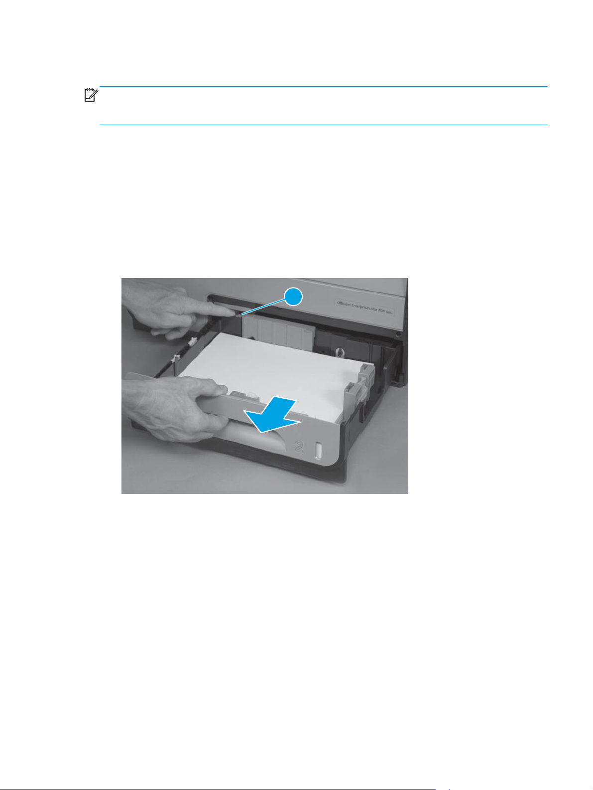
Pull out the tray, and then press the latch (callout 1) in left-rear corner of the tray to remove it from the
product.
Figure 1-1 Remove Tray 2
1
Ink cartridges
The product uses four colors and has a different ink cartridge for each color: yellow (Y), cyan (C), magenta
(M), and black (K).
ENWW Removal and replacement procedures 5
Page 20
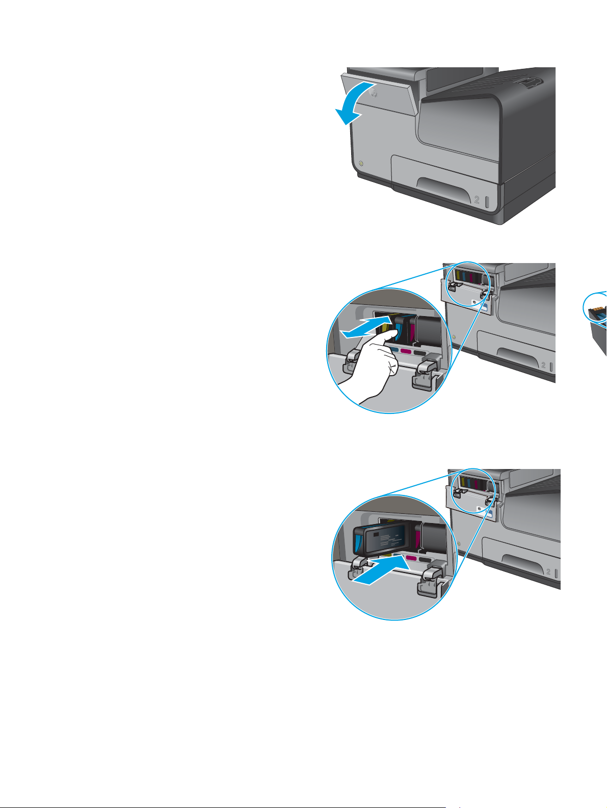
1. Open the ink cartridge door.
2. Push the old ink cartridge inward to unlock it, and
then pull the cartridge straight out to remove it.
CAUTION: When handling the new ink
cartridges, do not touch the gold-colored metal
contacts on the cartridges. Fingerprints on the
contacts can cause print-quality problems.
3. Insert the new ink cartridge into the product,
push the cartridge until it “clicks” into place, and
then close the ink cartridge door.
4. Place the old cartridge in the box. Refer to the
box for information about recycling used ink
cartridges.
6 Chapter 1 Removal and replacement ENWW
Page 21
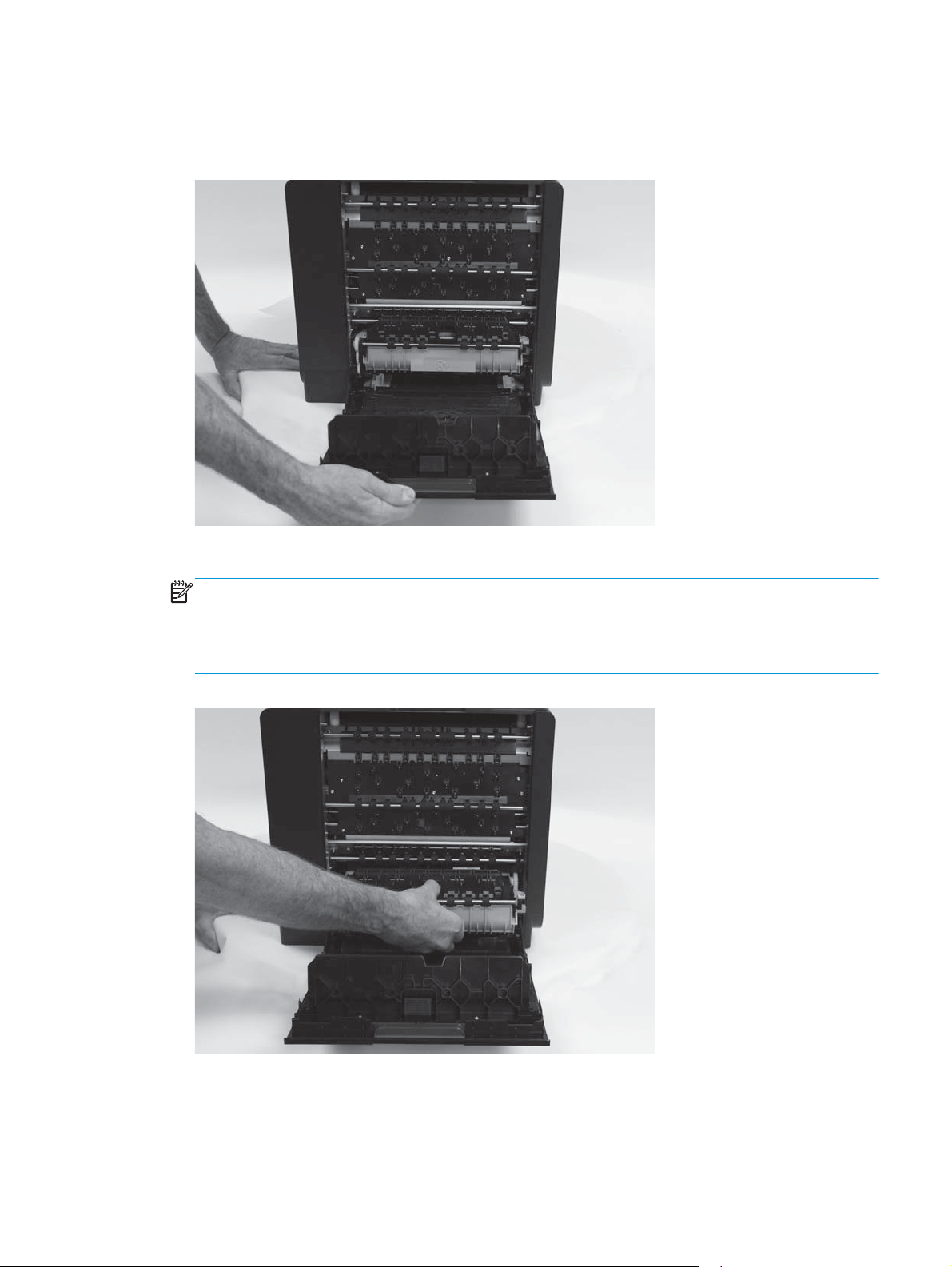
Ink collection unit
1. Open the left door.
Figure 1-2 Remove the ink collection unit (1 of 2)
2. Use the green hand-grip to pull the ink collection unit out of the product.
NOTE: When removing the ink collection unit, avoid making direct contact with the black cylinder to
prevent ink smear on skin or clothes. Keep the ink collection unit level to avoid spilling any waste ink.
Also, do not let the bottom of the ink collection unit touch or rest on the ribs on the left door, which can
damage them and might lead to media damage and jams.
Figure 1-3 Remove the ink collection unit (2 of 2)
ENWW Removal and replacement procedures 7
Page 22
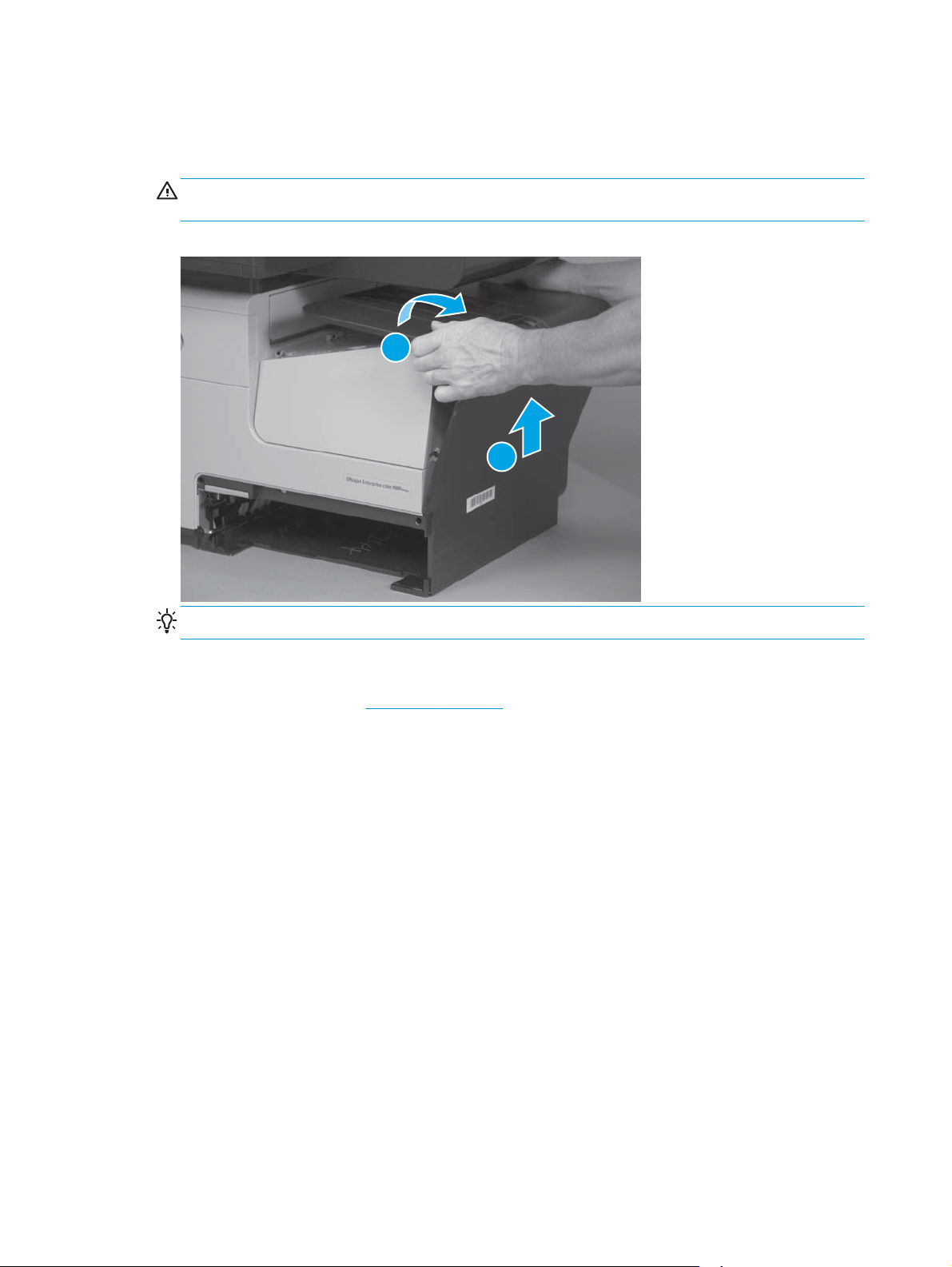
Output bin
▲
Lift and unsnap the output bin tabs below the output flap, and then lift the output bin to remove it from
the product.
CAUTION: Do not tilt the assembly too far back, as it will damage tabs at bottom seam of the output
bin.
Figure 1-4 Remove the output bin
1
2
Output bin flap
1. Remove the output bin. See
Reinstallation tip Insert the tabs on the bottom edge first, and then snap the top edge into place.
Output bin on page 8.
8 Chapter 1 Removal and replacement ENWW
Page 23
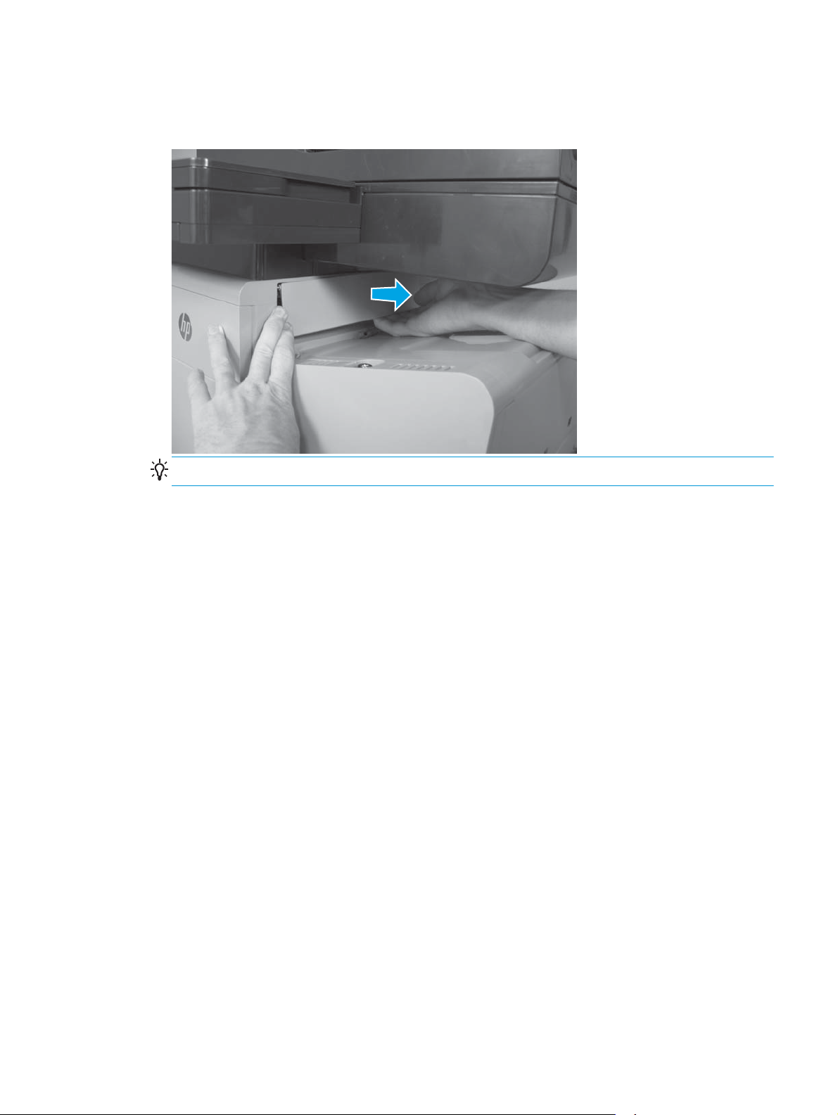
2. Slightly open the output bin flap, flex the middle of the output bin flap, and then remove the flap by
pulling the right pin away from the product first.
Figure 1-5 Remove the output bin flap
Reinstallation tip Insert the left pin into the product first when reinstalling the flap.
ENWW Removal and replacement procedures 9
Page 24
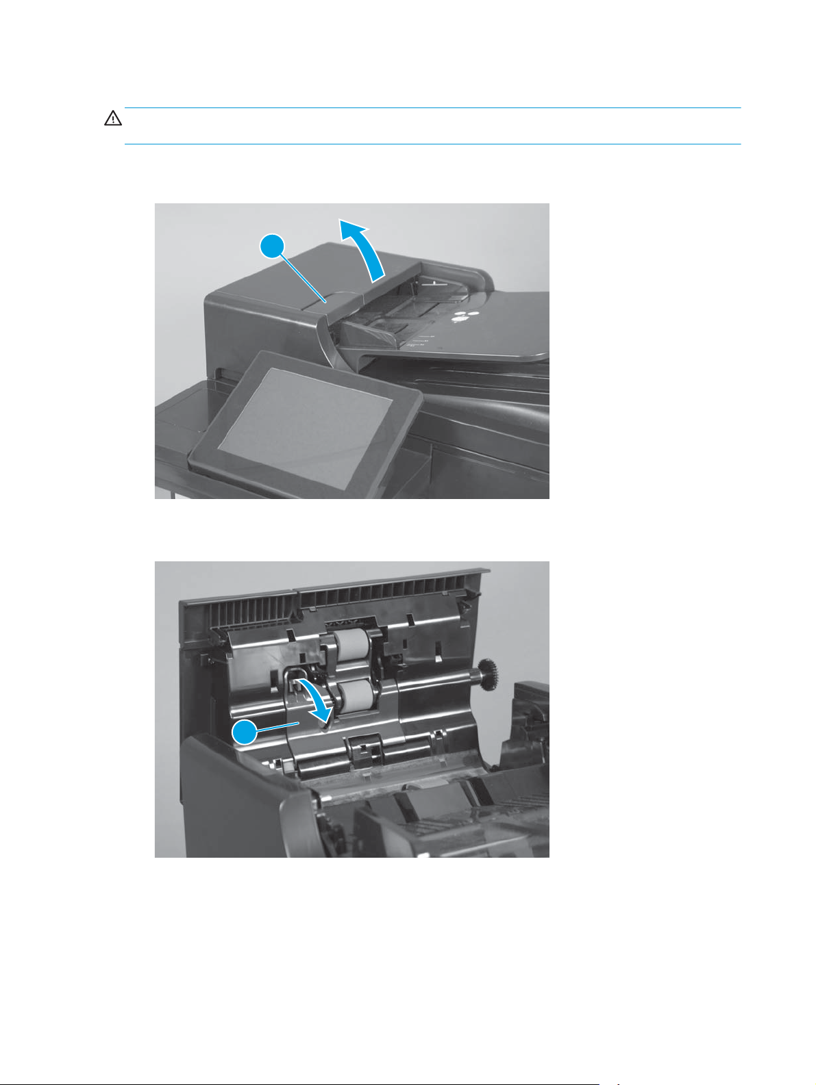
Document feeder roller (X585 models)
CAUTION: If you are replacing the roller, do not touch the surface of the replacement roller. Skin oils
deposited on the roller might cause paper pickup problems.
1. Pull the latch (callout 1) to open the document feeder door.
Figure 1-6 Remove the document-feeder roller (1 of 3)
1
2. Release one tab, and then open the access cover (callout 1).
Figure 1-7 Remove the document-feeder roller (2 of 3)
1
10 Chapter 1 Removal and replacement ENWW
Page 25
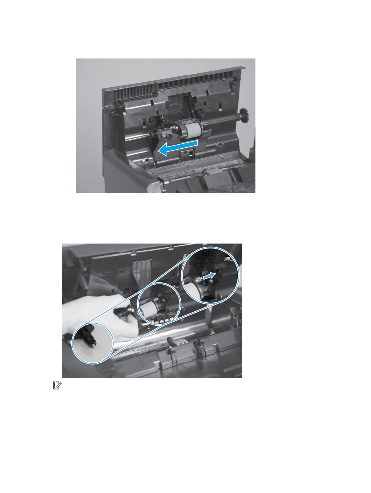
3. Slide the roller assembly left, and then lift it up and out of the product.
Figure 1-8 Remove the document-feeder roller (3 of 3)
Reinstall the document-feeder roller
The roller assembly is keyed. When reinstalling the roller assembly, position the hex-shaped fitting on the
shaft toward the rear of the product.
Figure 1-9 Reinstall the document-feeder roller
IMPORTANT: When the roller is reinstalled, the access door must be fully closed. When you close the door,
you should hear two audible clicks. If, after replacing the roller document feeder, a document feeder jam
message appears on the control panel display, make sure that the access door is fully closed.
ENWW Removal and replacement procedures 11
Page 26
Document feeder separation pad spring (X585 models)
CAUTION: Do not touch the surface of the separation pad. Skin oils deposited on the pad might cause paper
pickup problems.
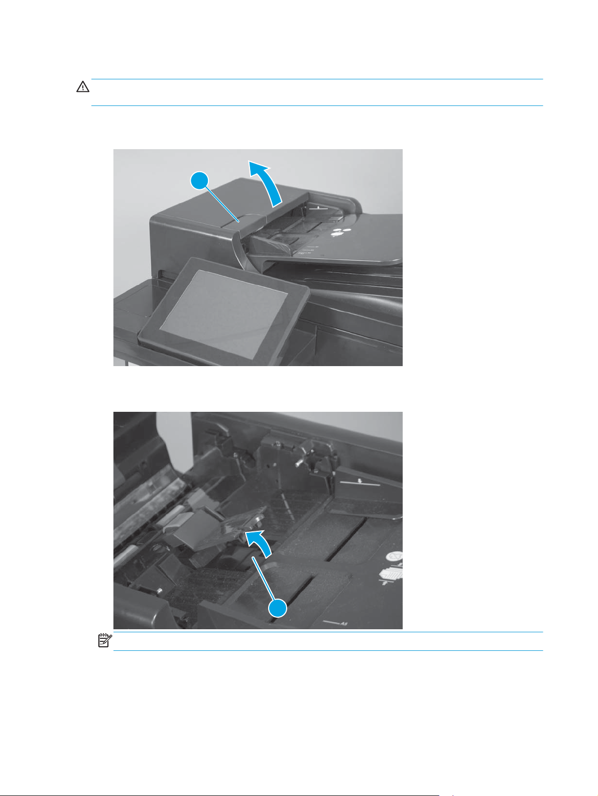
1. Pull the latch (callout 1) to open the document feeder door.
Figure 1-10 Remove the document-feeder separation pad spring (1 of 3)
1
2. Release one tab (callout 1) to open the separation pad assembly.
Figure 1-11 Remove the document-feeder separation pad spring (2 of 3)
1
NOTE: The separation pad assembly is spring-loaded and partially rises when the tab is released.
12 Chapter 1 Removal and replacement ENWW
Page 27
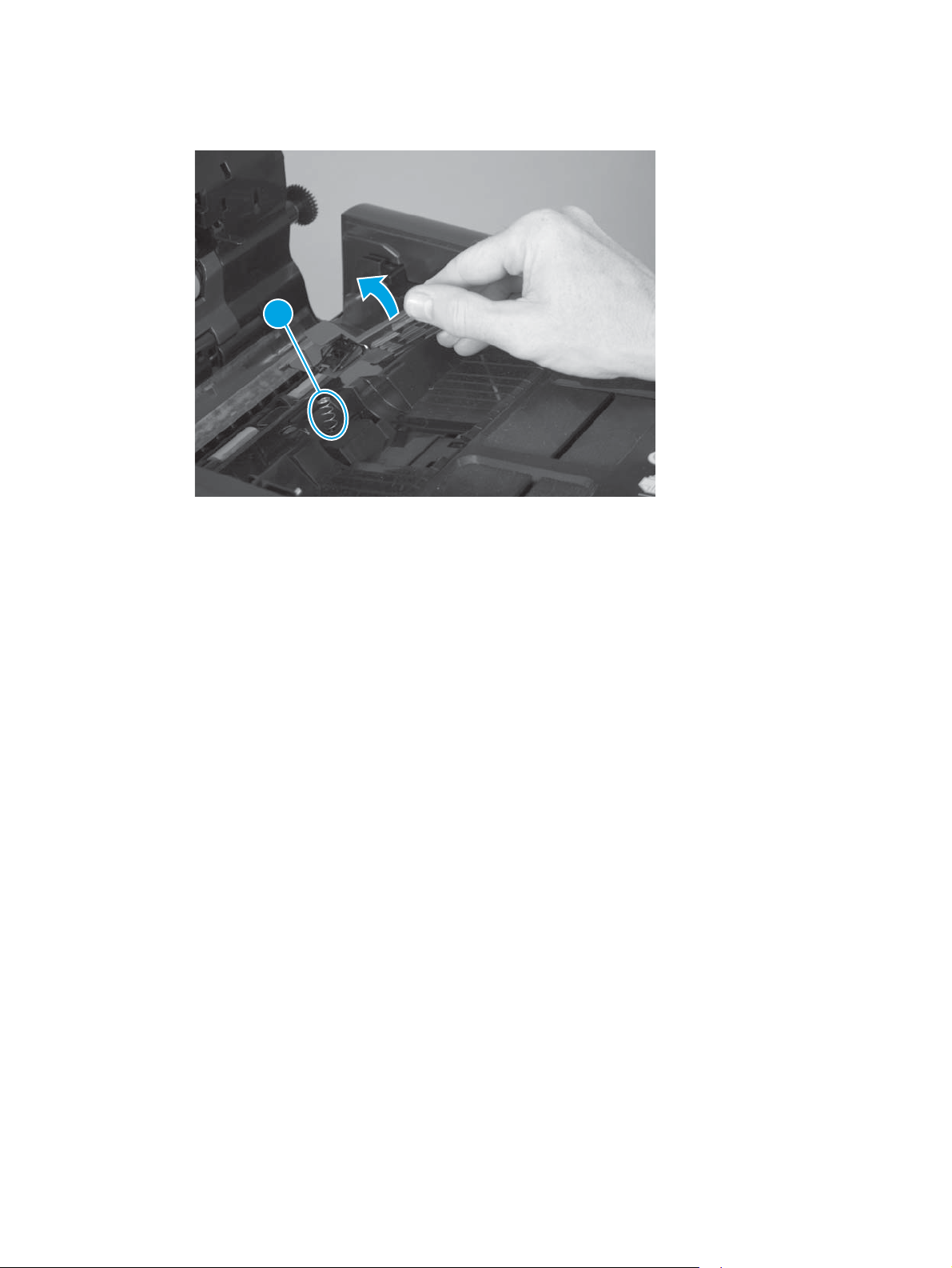
3. Lift the separation pad assembly up and away from the product, and then remove the spring (callout 1).
Figure 1-12 Remove the document feeder separation pad spring (3 of 3)
1
ENWW Removal and replacement procedures 13
Page 28
Document feeder white backing (X585 models)
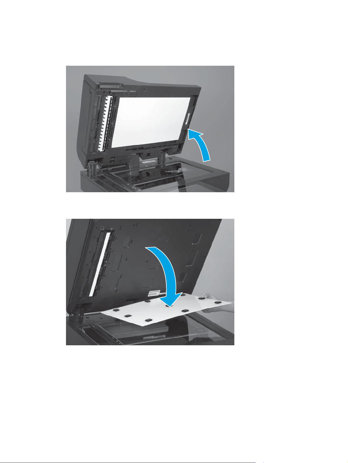
1. Open the document feeder.
Figure 1-13 Remove the document feeder white backing (1 of 3)
2. Carefully remove the white backing.
Figure 1-14 Remove the document feeder white backing (2 of 3)
14 Chapter 1 Removal and replacement ENWW
Page 29
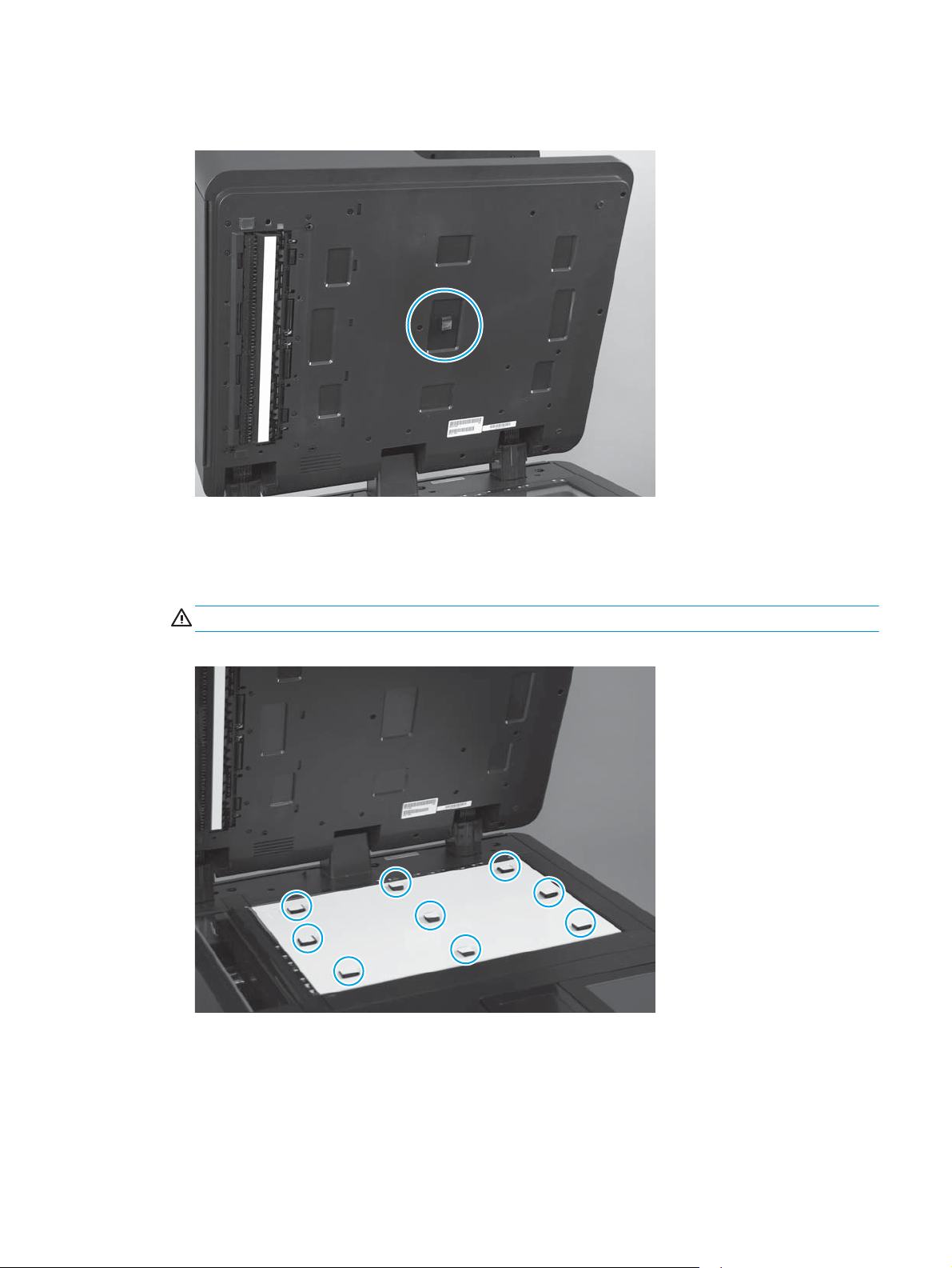
3. Remove any rubber stoppers that might still be attached to the document feeder.
Figure 1-15 Remove the document feeder white backing (3 of 3)
Install a replacement document feeder white backing
1. Position the replacement white backing on the scanner glass. Carefully remove the protective backing
from the rubber stoppers.
CAUTION: Do not touch the exposed adhesive.
Figure 1-16 Install a replacement document feeder white backing (1 of 6)
ENWW Removal and replacement procedures 15
Page 30
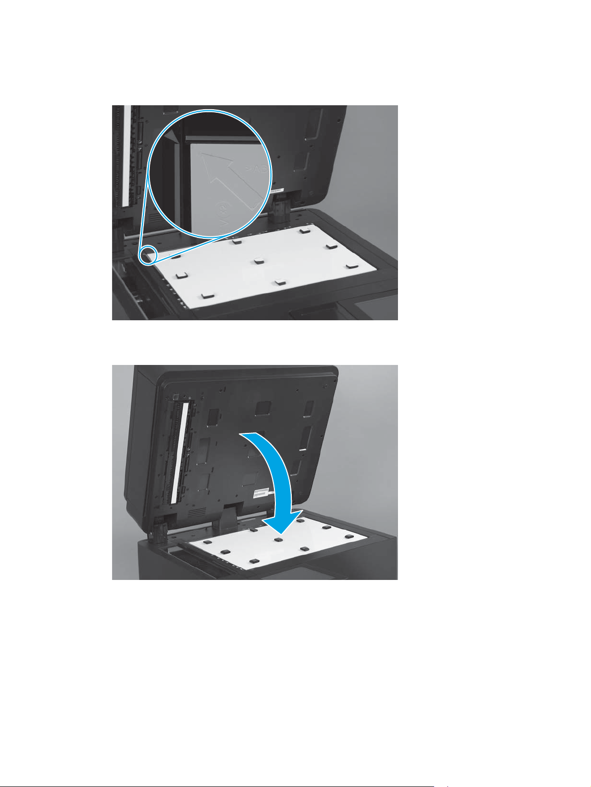
2. Make sure that the arrow on the replacement white backing is positioned in the upper-left corner of the
scanner glass.
Figure 1-17 Install a replacement document feeder white backing (2 of 6)
3. Completely close the document feeder.
Figure 1-18 Install a replacement document feeder white backing (3 of 6)
16 Chapter 1 Removal and replacement ENWW
Page 31

4. Firmly push down on the four corners of the document feeder to adhere the white backing to the
document feeder.
Figure 1-19 Install a replacement document feeder white backing (4 of 6)
5. Carefully open the document feeder.
Figure 1-20 Install a replacement document feeder white backing (5 of 6)
ENWW Removal and replacement procedures 17
Page 32

6. Firmly press on the white backing over the areas shown below to make sure that the rubber stoppers
are completely adhered to the document feeder.
Figure 1-21 Install a replacement document feeder white backing (6 of 6)
18 Chapter 1 Removal and replacement ENWW
Page 33

Background selector (X585 Flow models only)
1. Pull the latch (callout 1) to open the document feeder door.
Figure 1-22 Remove the background selector (1 of 4)
1
2. Lift the input tray up.
Figure 1-23 Remove the background selector (2 of 4)
ENWW Removal and replacement procedures 19
Page 34

3. Release two tabs (callout 1) on the selector.
Figure 1-24 Remove the background selector (3 of 4)
1
4. Slide the background selector away from the product to remove it.
Figure 1-25 Remove the background selector (4 of 4)
20 Chapter 1 Removal and replacement ENWW
Page 35

Reinstall the background selector
Push in on the background selector until the tabs snap into place.
NOTE: If jams occur after the assembly is installed, make sure that the assembly is fully seated.
Figure 1-26 Reinstall the background selector
Control panel (X555 models)
1. Tilt the control panel away from the product.
Figure 1-27 Remove the control panel — X555 models (1 of 4)
ENWW Removal and replacement procedures 21
Page 36

2. Remove the access cover behind the control panel.
Figure 1-28 Remove the control panel — X555 models (2 of 4)
3. Turn the lock lever counterclockwise to release it.
Figure 1-29 Remove the control panel — X555 models (3 of 4)
1
22 Chapter 1 Removal and replacement ENWW
Page 37

4. Lift the left end of the control panel up, and then disconnect three connectors (callout 1) and the ground
wire (callout 2).
Figure 1-30 Remove the control panel — X555 models (4 of 4)
Control panel (X585 models)
1
2
1. Tilt the control panel up, and then open and remove the access cover.
Figure 1-31 Remove the control panel — X585 models (1 of 4)
ENWW Removal and replacement procedures 23
Page 38

2. Disconnect two cables (callout 1).
NOTE: Flow models have a third cable, a flat, flexible cable (FFC) for the keyboard. You do not need to
detach this FFC.
Figure 1-32 Remove the control panel — X585 models (2 of 4)
1
3. Remove the thumbscrew (callout 1).
Figure 1-33 Remove the control panel — X585 models (3 of 4)
1
24 Chapter 1 Removal and replacement ENWW
Page 39

4. Slide the control panel to the left, and then carefully pull it away from the product to avoid damaging
the cables.
Figure 1-34 Remove the control panel — X585 models (4 of 4)
1
2
Remove the control panel keyboard (X585 Flow models only)
1. Remove the control panel. See
2. Disconnect the keyboard FFC (callout 1).
Figure 1-35 Remove the control panel keyboard — X585 Flow models (1 of 2)
Control panel (X585 models) on page 23.
1
ENWW Removal and replacement procedures 25
Page 40

3. Extend the keyboard, turn the control panel assembly over, and release two tabs (callout 1) to remove
the keyboard.
Figure 1-36 Remove the control panel keyboard — X585 Flow models (2 of 2)
1
26 Chapter 1 Removal and replacement ENWW
Page 41

CSR-B parts
CSR-B parts require tools during installation.
Formatter PCA
1. Remove the output bin. See
2. At the front of the product, disconnect the thumbscrew (callout 1), and then remove the formatter
cover from the product by lifting upward on it.
Figure 1-37 Remove the formatter PCA (1 of 3)
Output bin on page 8.
1
3. On the back of the product, disconnect two thumbscrews (callout 1).
Figure 1-38 Remove the formatter PCA (2 of 3)
1
ENWW Removal and replacement procedures 27
Page 42

4. At the front of the product, grab the formatter handle and pull the formatter out of the product.
Figure 1-39 Remove the formatter PCA (3 of 3)
Fax PCA (X585 fax models only)
1. Remove the formatter. See
2. On the formatter, remove one screw (callout 1) from the black fax card bracket, and then remove the
bracket.
Figure 1-40 Remove the fax PCA (1 of 2)
Formatter PCA on page 27.
1
28 Chapter 1 Removal and replacement ENWW
Page 43

3. Pull the fax PCA away from the formatter to disconnect the connector to the formatter.
Figure 1-41 Remove the fax PCA (2 of 2)
Solid state drive (SSD) (X555dn models only)
1. Remove the formatter. See
2. Locate the drive on the formatter, and then turn the lock tab (callout 1) counterclockwise.
Figure 1-42 Remove the SSD (1 of 2)
Formatter PCA on page 27.
1
ENWW Removal and replacement procedures 29
Page 44

3. Pull the lock tab out of the formatter, and then pull the SSD (callout 1) in the direction indicated to
disconnect it from the formatter.
NOTE: After replacing the SSD, you must reinstall the firmware. See Reinstall the product firmware
on page 31.
Figure 1-43 Remove the SSD (2 of 2)
1
Hard disk drive (HDD) (X555xh and all X585 models)
1. Remove the formatter. See
2. Locate the drive on the formatter, pull the latch tab (callout 1) toward the hard drive, and then move the
drive in the direction indicated to remove it from the formatter.
NOTE: After replacing the HDD, you must reinstall the firmware. See Reinstall the product firmware
on page 31.
Figure 1-44 Remove the HDD
Formatter PCA on page 27.
1
30 Chapter 1 Removal and replacement ENWW
Page 45

Reinstall the product firmware
NOTE: If you are installing a replacement HDD or SSM, use this procedure to install the product firmware on
the replacement drive.
If you are removing the HDD or SSM so that it can be installed on a replacement formatter, you can skip this
procedure.
1. Locate the product support Web site.
●
In the US:
◦
●
Outside the US:
a. Go to
b. Select your country/region.
c. Select Drivers & Downloads.
d. Enter the product name, and then click Go.
e. Select your product model.
2. Select Cross operating system (BIOS, Firmware, Diagnostics, etc.).
3. Locate the firmware download, and then select Download.
4. Copy the firmware upgrade file to the root directory of a USB flash drive. The firmware upgrade file has
a .bdl extension.
5. Insert the USB flash drive into the USB port on the product control panel, and then turn the product
power on.
6. The following message displays on the control panel: Error: 99.09.63 Incorrect Disk. Touch the OK
button to continue.
7. Wait for the Pre-Boot menu to appear on the control-panel display, and then touch the down arrow
button to scroll to 3 Administrator. Touch the OK button to select it.
www.hp.com/support/ojcolorX555 or www.hp.com/support/ojcolorMFPX585.
Go to
www.hp.com/support.
8. Touch the down arrow
9. Touch the down arrow
10. Touch the down arrow
11. The message Proceed with Requested Action displays. Touch the OK button to select it.
12. Touch the back
13. Touch the down arrow
14. Touch the down arrow
15. Touch the down arrow
ENWW Removal and replacement procedures 31
button to scroll to 6 Manage Disk. Touch the OK button to select it
button to scroll to + 6 Boot Device. Touch the OK button to select it.
button to scroll to 2 Erase / Unlock. Touch the OK button to select it
button to return to the Pre-Boot menu home screen.
button to scroll to 3 Administrator. Touch the OK button to select it.
button to scroll to 1 Download. Touch the OK button to select it.
button to scroll to 3 USB Thumbdrive. Touch the OK button to select it.
Page 46

16. Touch the down arrow button to scroll to the firmware upgrade file that you downloaded in step 4.
Touch the OK button to select it.
NOTE: If no .bdl files are listed, try saving the file to a different USB flash drive.
17. Wait while the file transfers. When the transfer is complete, the message Complete displays on the
screen.
18. Turn the product off, remove the USB flash drive, and then turn the product on. Wait for several minutes
while the product initializes.
32 Chapter 1 Removal and replacement ENWW
Page 47

Covers
Rear cover
1. Remove the following components.
●
Output bin. See
2. Remove one screw (callout 1) and one thumbscrew (callout 2).
Figure 1-45 Remove the rear cover (1 of 2)
Output bin on page 8.
1
3. Pull the cover to the right and remove it.
2
Left door
Figure 1-46 Remove the rear cover (2 of 2)
1. Lower the left door.
ENWW Removal and replacement procedures 33
Page 48

Figure 1-47 Remove left door (1 of 5)
2. Remove the ink collection unit.
Figure 1-48 Remove the left door (2 of 5)
34 Chapter 1 Removal and replacement ENWW
Page 49

3. Unhook each restraining strap by twisting the bottom end of the strap away from the door.
Figure 1-49 Remove the left door (3 of 5)
4. At the rear door hinge, the door is held in place by a retractable post. Insert a flat-blade screw driver
between the door hinge and the chassis to push the post (callout 1) toward the product rear, and then
pull that corner of the left door away from the product.
Figure 1-50 Remove the left door (4 of 5)
1
ENWW Removal and replacement procedures 35
Page 50

5. With the left end of the door free, remove the door.
Left rear cover
1. Remove the following components.
Figure 1-51 Remove the left door (5 of 5)
●
Ink collection unit. See
●
Left door. See
●
X555 models only: top cap. See
2. Remove two screws (callout 1).
Figure 1-52 Remove the left rear cover (1 of 2)
Left door on page 33.
Ink collection unit on page 7.
1
Top cover cap (X555 models only) on page 40.
36 Chapter 1 Removal and replacement ENWW
Page 51

3. Remove the cover by sliding the cover up 10 mm (0.4 in), and then rotating the cover away from the
product.
Figure 1-53 Remove the left rear cover (2 of 2)
NOTE: This cover can be very difficult to remove. You can use a flat-blade screwdriver to pry the
bottom edge of the cover away from the chassis.
Left front cover
1. Remove the following components:
●
●
2. Remove one screw (callout 1).
Figure 1-54 Remove the left front cover (1 of 2)
Left door. See
X555 models only: top cap. See
Left door on page 33.
Top cover cap (X555 models only) on page 40.
1
ENWW Removal and replacement procedures 37
Page 52

Top cover
3. Use a screwdriver to depress the tab (callout 1), and then remove the cover by sliding the it up 10 mm
(0.4 in), and then rotating the cover away from the product.
Figure 1-55 Remove the left front cover (2 of 2)
1
1. Remove the following components.
●
Rear cover. See
●
Left door. See
●
Left rear cover. See
●
Left front cover. See
●
Output bin flap. See
●
Control panel and control panel support. See
●
Scanner assembly. See
Rear cover on page 33.
Left door on page 33.
Left rear cover on page 36.
Left front cover on page 37.
Output bin flap on page 8.
Scanner assembly (X585 models only) on page 52.
Control panel (X585 models) on page 23.
38 Chapter 1 Removal and replacement ENWW
Page 53

2. Disconnect the control panel cable connectors (callout 1) from the main PCA.
Figure 1-56 Remove the top cover (1 of 4)
1
3. On the left side of the product, remove two screws (callout 1).
Figure 1-57 Remove the top cover (2 of 4)
1
ENWW Removal and replacement procedures 39
Page 54

4. Unthread the cables through the channel in the top cover.
NOTE: Unthread the cable with the 12-pin connector first, and then unthread the USB cable. Reverse
the procedure when reinstalling the cover. To pass the 12-pin connector through the top cover cable
channel, turn the connector sideways, parallel to the cable, and then pull it through the channel.
Figure 1-58 Remove the top cover (3 of 4)
5. X555 models: Lift the top cover to remove it.
X585 models: On the top cover, lift the left side part of the cover up and then slide the cover over the
scanner assembly support.
Figure 1-59 Remove the top cover (4 of 4)
1
2
Top cover cap (X555 models only)
1. Open the left door.
40 Chapter 1 Removal and replacement ENWW
Page 55

Figure 1-60 Remove the top cover cap (1 of 2)
2. Use a small, flat-blade screwdriver to loosen the top cover cap at three tab points (callout 1), and then
pull the cap from the product chassis.
Figure 1-61 Remove the top cover cap (2 of 2)
Front cover
1. Remove the following components:
●
Scanner assembly. See
●
Top cover. See
1
Scanner assembly (X585 models only) on page 52.
Top cover on page 38.
ENWW Removal and replacement procedures 41
Page 56

2. Remove one screw (callout 1).
Figure 1-62 Remove the front cover (1 of 2)
1
3. Remove the front cover.
NOTE: When removing the front cover, be aware that the power button (callout 1) has a cover that can
come loose when the front cover is removed.
Right cover
1. Remove the following components:
Figure 1-63 Remove the front cover (2 of 2)
1
●
Scanner assembly. See
Scanner assembly (X585 models only) on page 52.
●
Top cover. See
42 Chapter 1 Removal and replacement ENWW
Top cover on page 38.
Page 57

●
Front cover. See
Front cover on page 41.
●
Rear cover. See
2. Remove three screws (callout 1).
Figure 1-64 Remove the right cover (1 of 2)
Rear cover on page 33.
1
3. Remove the right cover from the product.
Figure 1-65 Remove the right cover (2 of 2)
ENWW Removal and replacement procedures 43
Page 58

Main assemblies
Document feeder mylar strip (X585 models)
1. Pull the latch (callout 1) to open the document feeder door.
Figure 1-66 Remove the document feeder mylar strip (1 of 4)
1
2. Locate the mylar strip.
Figure 1-67 Remove the document feeder mylar strip (2 of 4)
44 Chapter 1 Removal and replacement ENWW
Page 59

3. Carefully remove the mylar strip.
Figure 1-68 Remove the document feeder mylar strip (3 of 4)
4. Use your finger to remove any adhesive that remains after removing the mylar strip.
Figure 1-69 Remove the document feeder mylar strip (4 of 4)
Install a replacement document feeder mylar strip
Use the following guidelines when you install the replacement mylar strip:
1. Skin oils on the mylar strip can cause paper pickup problems. Wash your hands before handling the
replacement mylar strip.
2. When handling the replacement mylar strip, do not touch the adhesive portion of the strip.
ENWW Removal and replacement procedures 45
Page 60

3. Position the replacement mylar strip as shown, with the rounded corners on the strip facing the
document tray.
NOTE: Make sure that the adhesive side of the guide is face down.
Figure 1-70 Install a replacement document feeder mylar strip (1 of 2)
4. Press down firmly on the strip to adhere it to the product.
Figure 1-71 Install a replacement document feeder mylar strip (2 of 2)
Document feeder assembly (X585 models only)
1. At the back of the scanner assembly, use a Torx T10 screwdriver to remove two screws (callout 1) from
the scanner assembly back cover, and then pull the bottom of the cover away from the product to
remove the cover.
46 Chapter 1 Removal and replacement ENWW
Page 61

Figure 1-72 Remove the document feeder (1 of 6)
1
Reinstallation tip Line up the tabs on the bottom of the cover first, and then snap the rest of the
cover in place.
2. At the base of the document feeder hinges, use a Phillips screwdriver to remove two screws (callout 1).
Figure 1-73 Remove the document feeder (2 of 6)
1
ENWW Removal and replacement procedures 47
Page 62

3. Remove a cable clip screw (callout 1), two connectors (callout 2) on the scanner control board (SCB),
remove the ground wire screw (callout 3), and then remove one more screw (callout 4).
Figure 1-74 Remove the document feeder (3 of 6)
1
4
3
2
4. Remove one screw (callout 1), and then pull the SCB partially out of the product.
X585 Flow models only: Disconnect the flat flexible cable (callout 2).
Figure 1-75 Remove the document feeder (4 of 6)
1
2
48 Chapter 1 Removal and replacement ENWW
Page 63

5. X585 Flow models only: Unclip and remove the lower FFC ferrite (callout 1) from the assembly. This will
make it easier to install the document feeder.
Figure 1-76 Remove the document feeder (5 of 6)
1
6. Open the document feeder lid and tilt the assembly toward the back of the product as far as possible,
and then lift the document feeder up to remove it.
Figure 1-77 Remove the document feeder (6 of 6)
1
2
NOTE: If the document feeder is not tipped back as far as possible, it is difficult to remove.
Scanner control board (SCB) (X585 models only)
1. At the back of the scanner assembly, use a Torx T10 screwdriver to remove two screws (callout 1) from
the scanner assembly back cover, and then pull the bottom of the cover away from the product to
remove the cover.
ENWW Removal and replacement procedures 49
Page 64

Figure 1-78 Remove the SCB (1 of 6)
1
Reinstallation tip Line up the tabs on the bottom of the cover first, and then snap the rest of the
cover in place.
2. Remove a cable clip screw (callout 1), two connectors (callout 2) on the scanner control board (SCB),
remove the ground wire screw (callout 3), and then remove one more screw (callout 4).
Figure 1-79 Remove the SCB (2 of 6)
1
2
4
3
50 Chapter 1 Removal and replacement ENWW
Page 65

3. Remove one screw (callout 1), disconnect one connector (callout 2), and then pull the SCB partially out
of the product.
X585 Flow models only: Disconnect the flat flexible cable (callout 3).
Figure 1-80 Remove the SCB (3 of 6)
1
2
3
4. X585 Flow models only: Unclip and remove the lower FFC ferrite (callout 1) from the assembly. This will
make it easier to install the FFC.
NOTE: Unclip the ferrite by pulling it forward and rotating the back clips out first, then lift it up and
out.
Figure 1-81 Remove the SCB (4 of 6)
1
ENWW Removal and replacement procedures 51
Page 66

5. Disconnect two connectors (callout 1) and one FFC (callout 2).
Figure 1-82 Remove the SCB (5 of 6)
1 2
6. Pull the SCB away from the product to remove it.
Figure 1-83 Remove the SCB (6 of 6)
Scanner assembly (X585 models only)
1. Remove the following components:
●
Output bin. See
●
Document feeder. See
●
SCB. See
52 Chapter 1 Removal and replacement ENWW
Output bin on page 8.
Document feeder assembly (X585 models only) on page 46.
Scanner control board (SCB) (X585 models only) on page 49.
Page 67

●
Rear cover. See
Rear cover on page 33.
●
Control panel. See
2. Use a flat-blade screwdriver to remove the scanner base cover.
NOTE: This panel can be difficult to remove and might require some force to release it from the
scanner assembly. Reinstalling also requires some force to snap the cover in place.
Figure 1-84 Remove the scanner (1 of 7)
Control panel (X585 models) on page 23.
3. On the left side of the product, remove two screws (callout 1).
NOTE: The rear screw has a rubber plug over it. Use a flat-blade screwdriver to remove the plug to
access the screw.
Figure 1-85 Remove the scanner (2 of 7)
1
ENWW Removal and replacement procedures 53
Page 68

4. At the front of the product, inside the control panel support, remove two screws (callout 1), and then
pull the support away from the front of the unit.
Figure 1-86 Remove the scanner (3 of 7)
1
5. In the space where the control panel support was installed, remove one screw (callout 1).
Figure 1-87 Remove the scanner (4 of 7)
1
54 Chapter 1 Removal and replacement ENWW
Page 69

6. Unthread the two scanner cables.
Figure 1-88 Remove the scanner (5 of 7)
7. Move the scanner assembly toward the left side of the product.
Figure 1-89 Remove the scanner (6 of 7)
ENWW Removal and replacement procedures 55
Page 70

8. Lift the assembly to remove it.
Power supply
Figure 1-90 Remove the scanner (7 of 7)
CAUTION: Make sure that the power cable is disconnected from the product.
1. Remove the following components.
●
Output bin. See
●
Rear cover. See
2. Disconnect one connector (callout 1), and remove one screw (callout 2).
Figure 1-91 Remove the power supply (1 of 3)
Output bin on page 8.
Rear cover on page 33.
2
1
56 Chapter 1 Removal and replacement ENWW
Page 71

3. On the right side of the product, remove two screws (callout 1). Using a magnetic Torx T10 screwdriver
can be helpful when removing these screws.
Figure 1-92 Remove the power supply (2 of 3)
1
4. Slide the power supply out of the back side of the product.
Figure 1-93 Remove the power supply (3 of 3)
Print mechanism kits
Acclimation
Cold temperatures can affect the print mechanism
The print mechanism kit will not operate properly below 5° C (41° F). The product control panel will display an
error message.
ENWW Removal and replacement procedures 57
Page 72

Cold temperatures during kit storage or transportation might require extra time before installation to allow
the kit and ink cartridges to adjust to a warmer temperature (acclimation). Exposure to extended periods of
heat usually requires a minimal amount of acclimation time.
Exposure to extended periods of cold can cause condensation (moisture) to form on the parts when moved
into warmer areas. Condensation indicates the need for an acclimation period until the condensation
disappears. Exposure to extended cold (below 0° C (32° F)) can cause the ink inside the kit to freeze. The kit
and ink cartridges were designed to be exposed to freezing temperatures without being damaged. However,
if the ink is frozen and cannot flow properly during installation or during printing, errors might be reported on
the control panel or print quality might be poor, or possible damage will occur.
CAUTION: When unsure if the kit and ink cartridges need to be acclimated, always proceed as if they do
need to be acclimated. Acclimation will not damage these kits, but the failure to acclimate them can cause
errors or print quality issues, or possible damage can occur.
Acclimation process
1. Unpack the kit.
2. Open the doors or remove the covers, and pull out the input tray.
3. Leave the kit in the repair area until there is no visible condensation before proceeding with installation.
The print mechanism kit might need 2 to 4 hours to thaw depending on how frozen the shipping fluid is. The
shipping fluid is contained in the printbar, which is inside the print mechanism kit assembly.
The product might display error codes if there is an attempt to install a kit that is not acclimated completely.
Ink cartridge acclimation
Unpack the ink cartridges. It is important to remove the ink cartridges from their packaging and to separate
them to speed the acclimation process. The packaging will act as an insulation barrier and prevent frozen ink
from thawing quickly.
The ink cartridges might need 2 to 4 hours to thaw, depending on how frozen the ink is.
Move the ink cartridges into a warmer area and keep them separated to accelerate the thawing process.
Do not install ink cartridges that show visible condensation on the outside walls.
CAUTION: Check each ink cartridge’s electrical connection (gold colored contacts) for condensation before
installing them. Remove condensation by carefully blotting the electrical connections with a lint-free cloth.
To prevent damage, do not wipe or drag the cloth across the connections.
Installation notes
Keep the packaging
Do not destroy the box in which the new mechanism kit was shipped. You will use the box to return the
defective mechanism.
Necessary tools
This process requires the following tools:
58 Chapter 1 Removal and replacement ENWW
Page 73

●
Magnetized T10 Torx screwdriver
●
Magnetized Phillips no. 2 screwdriver
●
Small flat-blade screwdriver
Avoid cartridge issues
If the customer has activated the anti-theft feature on the ink cartridges, those cartridges must be installed
into the new mechanism after the initial purge and calibration – which uses the startup cartridges – but
before 15 pages are printed on the new mechanism.
Use the correct formatter
Do not power on the new mechanism with any formatter other than the formatter from the old mechanism.
Using another formatter will cause data loss and require another mechanism kit replacement.
Install the print mechanism kit (X555 models)
1. Remove the new mechanism kit from the box by lifting it out by the bag around it.
2. Remove all the blue shipping tape, and be sure to remove the cartridge shipping restraint in the ink
cartridge cavity.
NOTE: The shipping tape and restraint are reusable. Use the shipping tape and shipping restraint from
the new mechanism to prepare the old mechanism for shipping.
3. Install the startup cartridges included with the kit and load paper into Tray 2.
4. Turn off the old unit, and then disconnect the power cord and either the USB cable or the network cable.
5. From the old unit, remove the cartridges, and then insert the shipping cartridge restraint from the new
print mechanism into the old unit.
NOTE: You can re-use the old cartridges in the future but must use the startup cartridges sent with
the new kit for the setup initialization and calibration.
6. From the right side of the old product, remove the output bin. See Output bin on page 8.
7. From the rear of the old product, remove the rear cover. See
NOTE: In order to retain the model number, serial number, and regulatory information, the new kit
will contain a rear cover, but the rear cover from the failed unit needs to be moved to the new kit.
8. Remove the control panel. See Control panel (X555 models) on page 21.
9. Reverse the removal procedures above to attach the control panel to the new kit. Do not reinstall the
output bin or rear cover at this time.
10. From the front of the old product, loosen the thumbscrew on the formatter cover. Pull the cover
straight up to remove it.
11. From the rear of the old product, loosen the remaining thumbscrew on the formatter assembly. Use the
handle on the front of the product to pull the formatter assembly out of the product.
Rear cover on page 33.
12. Reverse the removal procedures to reinstall the formatter assembly in the new kit.
NOTE: Do not power on the new mechanism with any formatter other than the formatter from the old
unit. Using another formatter will cause data loss and require another product kit replacement.
ENWW Removal and replacement procedures 59
Page 74

13. From the rear of the old product, disconnect the power supply connector and remove one screw from
the power supply. See
14. From the right side of the product, remove two screws (use a magnetized T10 Torx screwdriver), and
pull the power supply straight out from the rear of the product.
15. Reverse the removal procedures to reinstall the power supply into the new unit.
NOTE: The new print mechanism includes a new power supply cable. Use this cable with the new print
mechanism, and return the old power supply cable with the defective unit.
16. Reinstall the formatter cover, rear cover, and output bin.
Reinstallation tip Reinstall the rear cover by inserting the right side tabs into the rear left cover, and
then snapping the remaining clips in place, moving to the left.
17. Reconnect the USB cable or the network cable, and then reconnect the power cord.
18. Turn on the product, and then allow it to initialize and calibrate. These processes will take
approximately 26 minutes. Make sure that Tray 2 contains paper.
NOTE: While the product is initializing, re-tape and box up the defective mechanism to be returned.
Install the print mechanism kit (X585 models)
1. Remove the new mechanism kit from the box by lifting it out by the bag around it.
Power supply on page 56.
2. Remove all the blue shipping tape, and be sure to remove the cartridge shipping restraint in the ink
cartridge cavity.
NOTE: The shipping tape and restraint are reusable. Use the shipping tape and shipping restraint from
the new mechanism to prepare the old mechanism for shipping.
3. Install the startup cartridges included with the kit and load paper into Tray 2.
4. Turn off the old unit, and then disconnect the power cord and either the USB cable or the network cable.
5. From the old unit, remove the cartridges, and then insert the shipping cartridge restraint from the new
print mechanism into the old unit.
NOTE: You can re-use the old cartridges in the future but must use the startup cartridges sent with
the new kit for the setup initialization and calibration.
6. From the right side of the old product, remove the output bin. See Output bin on page 8.
7. From the rear of the product, remove the rear cover. See
NOTE: In order to retain the model number, serial number, and regulatory information, the new mech
kit will contain a rear cover, but the rear cover from the failed unit needs to be moved to the new kit.
8. Remove the control panel. See Control panel (X585 models) on page 23.
NOTE: On models with the work flow keyboard, pull the keyboard out partly to provide more room to
remove the thumbscrew.
Rear cover on page 33.
60 Chapter 1 Removal and replacement ENWW
Page 75

9. From the front of the product, remove the two T10 Torx screws that secure the control panel support,
and then slide the support toward the front of the product to remove it.
NOTE: Hewlett-Packard recommends using a magnetic Torx driver to remove the control panel
support screws.
10. From the front of the product, remove the integrated scanner assembly retention screw. See Scanner
assembly (X585 models only) on page 52.
11. At the rear of the product, remove the two screws from the scanner assembly rear cover. Pull the
bottom of the cover away from the product to remove the rear scanner cover and chimney cover
assembly.
Reinstallation tip Align the lower retention hooks on the cover, and then snap the cover into place.
12. From the right side of the product, at the bottom of the scanner assembly, use a flat-blade screwdriver
to remove the scanner bottom cover. See
NOTE: Removing the cover requires a significant amount of force.
13. At the rear of the product, remove the power cable (the red and black cable) and the IPASS cable (the
red cables inside a black sheath).
●
On the power cable, depress the connector lock and lift the connector to unhook it. Remove the
cable from the cable stay. Pull the cable down through the channel.
Scanner assembly (X585 models only) on page 52.
●
On the IPASS cable, depress the connector lock to un-hook it. Pull the cable down through the
channel keeping the front of the connector facing the rear of the product to make it easier to pull
through the channel.
14. From the left side of the product, remove the two screws from the scanner.
NOTE: The rear screw has a rubber cover over it. Use a small flat-blade screwdriver to remove the
plug and gain access to the screw.
15. From the front of the product, slide the document feeder/scanner assembly toward the left side, and
then lift it to remove it.
16. The document feeder/scanner assembly now can be installed on the new kit. From the front of the new
kit, first align the cut out in the front of the assembly sheet metal with the control panel cable channel,
and then slide the assembly toward the right side to lock it into place.
17. Reverse the removal procedures above to attach the document feeder/scanner assembly and control
panel to the new kit. Do not reinstall the output bin, scanner bottom cover, or rear cover at this time.
18. From the front of the product, loosen the thumbscrew on the formatter cover. Pull the cover straight up
to remove it.
19. From the rear of the product, loosen the remaining thumbscrew on the formatter assembly. Use the
handle on the front of the product to pull the formatter assembly out of the product.
20. Reverse the removal procedures to reinstall the formatter assembly in the new kit.
NOTE: Do not power on the new mechanism with any formatter other than the formatter from the old
unit. Using another formatter will cause data loss and require another mechanism kit replacement.
ENWW Removal and replacement procedures 61
Page 76

21. From the rear of the product, disconnect the power supply connector and remove one screw from the
power supply. See
Power supply on page 56.
22. From the right side of the product, remove two screws (use a magnetized T10 Torx screwdriver), and
pull the power supply straight out from the rear of the old product.
23. Reverse the removal procedures to reinstall the power supply into the new unit.
NOTE: The new print mechanism includes a new power supply cable. Use this cable with the new print
mechanism, and return the old power supply cable with the defective unit.
24. Reinstall the formatter cover, the scanner base cover, the rear cover, and the output bin.
Reinstallation tip Reinstall the rear cover starting on the right side and snapping in the retaining clips
moving to the left.
25. Reconnect the USB cable or the network cable, and then reconnect the power cord.
26. Turn on the product, and then allow it to initialize and calibrate. These processes will take
approximately 26 minutes. Make sure that Tray 2 contains paper.
NOTE: While the product is initializing, re-tape and box up the defective mechanism to be returned.
62 Chapter 1 Removal and replacement ENWW
Page 77

2 Parts and diagrams
NOTE: In this chapter, part numbers are listed only for available replaceable parts.
●
Order parts by authorized service providers
●
How to use the parts lists and diagrams
●
Assembly locations—X555 models
●
Assembly locations—X585 models
●
Covers, control panels, and doors—X555 models
●
Covers, control panels, and doors—X585 models
●
Internal assemblies—all models
●
Scanner/document feeder assembly—X585 models
●
Alphabetical parts list
●
Numerical parts list
ENWW 63
Page 78

Order parts by authorized service providers
Order replacement parts
Table 2-1 Order parts, accessories, and supplies
Order supplies www.hp.com//go/suresupply.
Order genuine HP parts or accessories
Order through service or support providers Contact an HP-authorized service or support provider.
Order using the HP Embedded Web Server (EWS) To access, in a supported Web browser on your computer, enter the product IP
Related documentation and software
Table 2-2 Related documentation and software
Item Description Part number
HP Officejet Enterprise Color X555 User Guide Product user guide C2S11-90904
HP Officejet Enterprise Color MFP X585 User Guide B5L04-90904
HP Officejet Enterprise Color X555 and MFP X585 Repair Manual English repair manual (this
HP Officejet Enterprise Color X555 and MFP X585
Troubleshooting Manual
www.hp.com/buy/parts
address or host name in the address/URL field. The EWS contains a link to the
HP SureSupply Web site, which provides options for purchasing Original
HP supplies.
manual)
English troubleshooting
manual
Supplies part numbers
The following supplies are available for the product.
Table 2-3 Supplies part numbers
Item Part number Product number Cartridge number Type/size
Ink cartridges D8J10-67901 D8J10A HP 980A Standard-capacity black
D8J07-67901 D8J07A HP 980A Standard-capacity cyan
D8J09-67901 D8J09A HP 980A Standard-capacity yellow
D8J08-67901 D8J08A HP 980A Standard-capacity
ink cartridge with HP
Officejet pigment ink
ink cartridge with HP
Officejet pigment ink
ink cartridge with HP
Officejet pigment ink
magenta ink cartridge
with HP Officejet pigment
ink
64 Chapter 2 Parts and diagrams ENWW
Page 79

Table 2-3 Supplies part numbers (continued)
Item Part number Product number Cartridge number Type/size
Ink collection unit B5L04-67906 B5L09A HP Officejet Enterprise ink
Document feeder
roller maintenance
kit
(X585 models)
L2725-60002 L2718A Replacement rollers for
collection unit and duplex
module
X585 document feeder
NOTE: For information about the yield for the cartridges, see www.hp.com/go/pageyield. Actual yield
depends on specific use.
Some ink cartridges might not be available in all countries/regions.
The following accessories are available for the product.
Table 2-4 Product accessories
Item Part number Product number Description
Paper-handling
accessory
Paper tray cassette B5L04-67924 HP Officejet Enterprise 500-sheet paper tray cassette
B5L04-67923 B5L07A HP Officejet Enterprise 500-sheet feeder and paper
tray assembly (optional Tray 3)
(optional Tray 3)
Product cabinet and
stand
Network accessory J8029-61001 J8029A HP NFC/Wireless Direct Accessory
Fax accessory (X585
models only)
Wireless print server J8026-61001 J8026A USB wireless print server
USB cable 8121-0868 2-meter A-to-B cable
B5L04-67925 B5L08A HP Officejet Enterprise printer cabinet and stand
A2W77-67910 CC487A HP MFP Analog Fax Accessory 500
Customer self-repair parts
The following customer self-repair parts are available for the product.
Each kit includes parts and installation instructions. The customer self repair (CSR) level indicates the
expected difficulty the customer will experience when replacing this part:
●
A: Easy
●
B: More difficult
Table 2-5 Customer self-repair parts
Item Description CSR level Part number
Tray 2 cassette 500-sheet paper tray A B5L04-67911
ENWW Order parts by authorized service providers 65
Page 80

Table 2-5 Customer self-repair parts (continued)
Item Description CSR level Part number
Ink collection unit Waste ink collection unit and duplex module A B5L04-67906
Output bin Face-down output bin assembly A B5L04-67914
Eject assembly flap Output bin flap B B5L04-67913
Control panel assembly—X555
models
Control panel assembly—X585
models
Control panel keyboard
assembly, US English—X585
Flow models
Control panel keyboard
assembly, UK English—X585
Flow models
Control panel keyboard overlay
kits—X585 Flow models
Control panel assembly—X555 models A 5851-5950
Control panel assembly—X585 models A 5851-5952
Keyboard assembly for US English markets A 5851-5380
Keyboard assembly for UK English markets A 5851-5008
Keyboard overlay for the following languages: FR, IT, RU,
DE, ES
Keyboard overlay for the following languages: FR-CN, ESLA, ES
Keyboard overlay for the following languages: FR-SW,
DE-SW, DA
Keyboard overlay for the following languages: ZHTW,
ZHCN
Keyboard overlay for the following languages: ES, PT A 5851-6023
Keyboard overlay for the following languages: JA-KG, JA-KTA 5851-6024
A 5851-6019
A 5851-6020
A 5851-6021
A 5851-6022
Foam reflector—X585 models Document feeder foam reflector A 5851-6084
Document feeder maintenance
kit—X585 models
Document feeder separation
pad spring kit—X585 models
e-Duplex selector assembly—
X585 Flow models only
Formatter PCA—X555 models Formatter PCA for X555 models B C2S11-67904
Formatter PCA, China only—
X555 models
Formatter PCA—X585 models Formatter PCA for X585 models B B5L04-67908
Formatter PCA, China only—
X585 models
Fax PCA—X585 models HP LaserJet MFP Analog Fax Accessory 500 B A2W77-67910
Solid state memory (SSM)—
X555 models
Hard disk drive Hard disk drive assembly B B5L04-67909
Feed rollers for document feeder A L2725-60002
Separation pad spring for document feeder A 5851-4879
Selector for X585 Flow models A 5851-5022
Formatter PCA for X555 models, China only B C2S11-67905
Formatter PCA for X585 models, China only B B5L04-67907
SSM drive B C2S11-67901
66 Chapter 2 Parts and diagrams ENWW
Page 81

Table 2-5 Customer self-repair parts (continued)
Item Description CSR level Part number
Formatter access cover Formatter access cover A B5L04-67926
Left door assembly Left door/Tray 1 assembly B B5L04-67916
Left door strap, front Left door front strap B CN598-67002
Left door strap, rear Left door rear strap B CN598-67003
HIP cover—X555 models Cover for X555 hardware integration pocket B C2S11-40005
HIP cover—X585 models Cover for X585 hardware integration pocket B 5851-5361
Control panel access cover—
X555 models
Control panel access cover—
X585 models
Control panel USB cover—
X585 models
Access cover for X555 control panel A CZ255-40004
Access cover for X585 control panel A 5042-9118
USB port cover for X585 control panel A 5851-5360
ENWW Order parts by authorized service providers 67
Page 82

How to use the parts lists and diagrams
The figures in this chapter show the major subassemblies in the product and their component parts. A parts
list table follows each exploded view assembly diagram. Each table lists the item number, the associated
part number, and the description of each part. If a part is not listed in the table, then it is not a field
replacement unit (FRU).
NOTE: In this manual, the abbreviation “PCA” stands for “printed circuit-board assembly.” Components
described as a PCA might consist of a single circuit board or a circuit board plus other parts, such as cables
and sensors.
68 Chapter 2 Parts and diagrams ENWW
Page 83

Assembly locations—X555 models
Figure 2-1 Assembly locations—X555 models
21
15
14
13
1 Color touchscreen control panel
3 4 5
6
7
89101112
2 Hardware integration pocket (HIP)
3 Eject assembly flap
4 Output bin
5 Output bin extension
6 Left door (access for clearing jams)
7 Tray 1 (Multi-purpose tray)
8 USB host port accepts USB storage devices for Plug and Print
9 Ethernet port
10 USB 2.0 port accepts a USB cable from a computer (alternative to network and wireless connections)
11 Power connection
12 Tray 2 (main paper tray)
13 On/off button
14 Ink cartridge door
15 Walkup USB port
ENWW Assembly locations—X555 models 69
Page 84

Assembly locations—X585 models
Figure 2-2 Assembly locations—X585 models
2
1
3 4 5
24
23
22
c
a
p
s
l
o
c
k
A
s
h
i
f
t
S
D
F
Z
X
G
C
@
H
V
J
a
l
t
B
K
N
L
:
M
“
;
e
n
,
t
e
‘
r
?
.
a
l
t
s
h
i
f
t
/
21
20
1 Document feeder cover (access for clearing jams)
2 Document feeder input tray
3 Document feeder input tray extension
6
7
8
9
10
111213141516171819
4 Document feeder output bin
5 Output bin extension
6 Document feeder assembly
7 Scanner assembly
8 Walkup USB port
9 Left door (access for clearing jams)
10 Tray 1 (Multi-purpose tray)
11 Fax line port
12 USB host port accepts USB storage devices for Plug and Print
13 Foreign interface harness (FIH) port
14 Ethernet port
15 USB 2.0 port accepts a USB cable from a computer (alternative to network and wireless connections)
16 Power connection
17 Output bin
18 Eject assembly flap
19 Tray 2 (main paper tray)
20 On/off button
70 Chapter 2 Parts and diagrams ENWW
Page 85

21 Ink cartridge door
22 Keyboard (X585 Flow models only)
23 Hardware integration pocket (HIP)
24 Color touchscreen control panel
ENWW Assembly locations—X585 models 71
Page 86

Covers, control panels, and doors—X555 models
Figure 2-3 Covers, control panels, and doors—X555 models
11
12
15
10
16
1
2
4
9
6
3
14
13
7
5
8
72 Chapter 2 Parts and diagrams ENWW
Page 87

Table 2-8 Covers, control panels, and doors—X555 models
Ref Description Part number Qty
1 Rear cover B5L04-67915 1
2 Eject assembly flap B5L04-67913 1
3 Output bin B5L04-67914 1
4 Right cover B5L04-67920 1
5 Front cover B5L04-67919 1
6 Formatter access cover B5L04-67926 1
7 Left door, tray 1 assembly B5L04-67916 1
8 Strap, left door, front CN598-67002 1
9 Strap, left door, rear CN598-67003 1
10 Left rear cover B5L04-67918 1
11 Left front cover B5L04-67917 1
12 Top cover cap C2S11-67903 1
13 Top cover C2S11-67902 1
14 Control panel 5851-5950 1
15 Control panel access cover CZ255-40004 1
16 HIP cover C2S11-40005 1
ENWW Covers, control panels, and doors—X555 models 73
Page 88

Covers, control panels, and doors—X585 models
Figure 2-4 Covers, control panels, and doors—X585 models
15
14
16
13
12
17
18
1
2
4
10
9
7
3
5
11
74 Chapter 2 Parts and diagrams ENWW
8
6
Page 89

Table 2-9 Covers, control panels, and doors—X585 models
Ref Description Part number Qty
1 Rear cover B5L04-67915 1
2 Eject assembly flap B5L04-67913 1
3 Output bin B5L04-67914 1
4 Right cover B5L04-67920 1
5 Front cover B5L04-67919 1
6 Formatter access cover B5L04-67926 1
7 Left door, tray 1 assembly B5L04-67916 1
8 Strap, left door, front CN598-67002 1
9 Strap, left door, rear CN598-67003 1
10 Left rear cover B5L04-67918 1
11 Left front cover B5L04-67917 1
12 US English keyboard (flow models) 5851-5380 1
12 UK English keyboard (flow models) 5851-5008 1
13 Keyboard overlay (flow models)—FR, IT, RU, DE, ES 5851-6019 1
13 Keyboard overlay (flow models)—FR-CN, ES-LA, ES 5851-6020 1
13 Keyboard overlay (flow models)—FR-SW, DE-SW, DA 5851-6021 1
13 Keyboard overlay (flow models)—ZHTW, ZHCN 5851-6022 1
13 Keyboard overlay (flow models)—ES, PT 5851-6023 1
13 Keyboard overlay (flow models)—JA-KG, JA-KT 5851-6024 1
14 Control panel USB cover 5851-5360 1
15 HIP cover 5851-5361 1
16 Control panel access cover 5042-9118 1
17 Control panel assembly 5851-5952 1
18 Top cover B5L04-67921 1
ENWW Covers, control panels, and doors—X585 models 75
Page 90

Internal assemblies—all models
Figure 2-5 Internal assemblies
7
1
2
6
5
4
3
76 Chapter 2 Parts and diagrams ENWW
Page 91

Table 2-10 Internal assemblies
Ref Description Part number Qty
1 Single-fuction print mechanism kit (X555 models) C2S11-69001 1
1 Multi-function print mechanism kit (X585 models) B5L04-69001 1
2 Power supply, universal 110V and 220V B5L04-67910 1
3 Tray 2 assembly B5L04-67911 1
4 Formatter PCA assembly, X555 models C2S11-67904 1
4 Formatter PCA assembly—China only, X555 models C2S11-67905 1
4 Formatter PCA assembly, X585 models B5L04-67908 1
4 Formatter PCA assembly—China only, X585 models B5L04-67907 1
5 Hard disk drive assembly B5L04-67909 1
5 Solid state drive (some X555 models only) C2S11-67901 1
6 Fax PCA (some X585 models only) A2W77-67910 1
7 Ink collection unit B5L04-67906 1
ENWW Internal assemblies—all models 77
Page 92

Figure 2-6 Internal assemblies—print mechanism kit
3
1
2
78 Chapter 2 Parts and diagrams ENWW
Page 93

Table 2-11 Internal assemblies—print mechanism kit
Ref Description Part number Qty
1 Single function print mechanism kit C2S11-69001 1
1 Multifunction print mechanism kit B5L04-69001 1
2 Tray 2 assembly B5L04-67911 1
3 Ink collection unit B5L04-67906 1
1
The print mechanism kit illustration is for descriptive purposes. A new print mechanism kit comes complete with covers, a new tray 2
assembly, and an ink collection unit. See the instructions included with the print mechanism kit for more repair detail.
ENWW Internal assemblies—all models 79
Page 94

Scanner/document feeder assembly—X585 models
2
0
4
3
6
8
9
7
5
Figure 2-7 Scanner/document feeder assembly—X585 models
3
2
1
4
5
6
7
8
10
1
9
80 Chapter 2 Parts and diagrams ENWW
Page 95

Table 2-12 Scanner/document feeder assembly—X585 models
Ref Description Part number Qty
1 Scanner assembly B5L04-67903 1
2 Automatic document feeder—standard B5L04-67901 1
2 Automatic document feeder—flow models B5L04-67902 1
3 Mylar kit 5851-4998 1
4 Document feeder roller kit L2725-60002 1
5 Document feeder separation pad spring 5851-4879 1
6 Scanner/document feeder rear cover B5L04-67905 1
7 Scanner control board PCA, standard models B5L04-67904 1
7 Scanner control board PCA, flow models B5L06-67901 1
8 Selector, document feeder e-duplex assembly (flow models only) 5851-5022 1
9 Scanner/document feeder lower cover B5L04-67922 1
10 Document feeder foam reflector 5851-6084 1
ENWW Scanner/document feeder assembly—X585 models 81
Page 96

Alphabetical parts list
Table 2-13 Alphabetical parts list
Description Part number Table and page
Automatic document feeder—flow models B5L04-67902
Automatic document feeder—standard B5L04-67901
Control panel 5851-5950
Control panel access cover CZ255-40004
Control panel access cover 5042-9118
Control panel assembly 5851-5952
Control panel USB cover 5851-5360
Document feeder foam reflector 5851-6084
Document feeder roller kit L2725-60002
Scanner/document feeder
assembly—X585 models
on page 81
Scanner/document feeder
assembly—X585 models
on page 81
Covers, control panels, and
doors—X555 models on page 73
Covers, control panels, and
doors—X555 models on page 73
Covers, control panels, and
doors—X585 models on page 75
Covers, control panels, and
doors—X585 models on page 75
Covers, control panels, and
doors—X585 models on page 75
Scanner/document feeder
assembly—X585 models
on page 81
Scanner/document feeder
assembly—X585 models
on page 81
Document feeder separation pad spring 5851-4879
Eject assembly flap B5L04-67913
Eject assembly flap B5L04-67913
Fax PCA (some X585 models only) A2W77-67910
Formatter access cover B5L04-67926
Formatter access cover B5L04-67926
Formatter PCA assembly, X555 models C2S11-67904
Formatter PCA assembly, X585 models B5L04-67908
Formatter PCA assembly—China only, X555 models C2S11-67905
Formatter PCA assembly—China only, X585 models B5L04-67907
Front cover B5L04-67919
Scanner/document feeder
assembly—X585 models
on page 81
Covers, control panels, and
doors—X555 models on page 73
Covers, control panels, and
doors—X585 models on page 75
Internal assemblies on page 77
Covers, control panels, and
doors—X555 models on page 73
Covers, control panels, and
doors—X585 models on page 75
Internal assemblies on page 77
Internal assemblies on page 77
Internal assemblies on page 77
Internal assemblies on page 77
Covers, control panels, and
doors—X555 models on page 73
82 Chapter 2 Parts and diagrams ENWW
Page 97

Table 2-13 Alphabetical parts list (continued)
Description Part number Table and page
Front cover B5L04-67919
Hard disk drive assembly B5L04-67909
HIP cover C2S11-40005
HIP cover 5851-5361
Ink collection unit B5L04-67906
Ink collection unit B5L04-67906
Keyboard overlay (flow models)—ES, PT 5851-6023
Keyboard overlay (flow models)—FR, IT, RU, DE, ES 5851-6019
Keyboard overlay (flow models)—FR-CN, ES-LA, ES 5851-6020
Keyboard overlay (flow models)—FR-SW, DE-SW, DA 5851-6021
Keyboard overlay (flow models)—JA-KG, JA-KT 5851-6024
Covers, control panels, and
doors—X585 models on page 75
Internal assemblies on page 77
Covers, control panels, and
doors—X555 models on page 73
Covers, control panels, and
doors—X585 models on page 75
Internal assemblies on page 77
Internal assemblies—print
mechanism kit on page 79
Covers, control panels, and
doors—X585 models on page 75
Covers, control panels, and
doors—X585 models on page 75
Covers, control panels, and
doors—X585 models on page 75
Covers, control panels, and
doors—X585 models on page 75
Covers, control panels, and
doors—X585 models on page 75
Keyboard overlay (flow models)—ZHTW, ZHCN 5851-6022
Left door, tray 1 assembly B5L04-67916
Left door, tray 1 assembly B5L04-67916
Left front cover B5L04-67917
Left front cover B5L04-67917
Left rear cover B5L04-67918
Left rear cover B5L04-67918
Multi-function print mechanism kit (X585 models) B5L04-69001
Multifunction print mechanism kit
1
B5L04-69001 Internal assemblies—print
Mylar kit 5851-4998
Output bin B5L04-67914
Covers, control panels, and
doors—X585 models on page 75
Covers, control panels, and
doors—X555 models on page 73
Covers, control panels, and
doors—X585 models on page 75
Covers, control panels, and
doors—X555 models on page 73
Covers, control panels, and
doors—X585 models on page 75
Covers, control panels, and
doors—X555 models on page 73
Covers, control panels, and
doors—X585 models on page 75
Internal assemblies on page 77
mechanism kit on page 79
Scanner/document feeder
assembly—X585 models
on page 81
Covers, control panels, and
doors—X555 models on page 73
ENWW Alphabetical parts list 83
Page 98

Table 2-13 Alphabetical parts list (continued)
Description Part number Table and page
Output bin B5L04-67914
Power supply, universal 110V and 220V B5L04-67910
Rear cover B5L04-67915
Rear cover B5L04-67915
Right cover B5L04-67920
Right cover B5L04-67920
Scanner assembly B5L04-67903
Scanner control board PCA, flow models B5L06-67901
Scanner control board PCA, standard models B5L04-67904
Scanner/document feeder lower cover B5L04-67922
Covers, control panels, and
doors—X585 models on page 75
Internal assemblies on page 77
Covers, control panels, and
doors—X555 models on page 73
Covers, control panels, and
doors—X585 models on page 75
Covers, control panels, and
doors—X555 models on page 73
Covers, control panels, and
doors—X585 models on page 75
Scanner/document feeder
assembly—X585 models
on page 81
Scanner/document feeder
assembly—X585 models
on page 81
Scanner/document feeder
assembly—X585 models
on page 81
Scanner/document feeder
assembly—X585 models
on page 81
Scanner/document feeder rear cover B5L04-67905
Selector, document feeder e-duplex assembly (flow models only) 5851-5022
Single function print mechanism kit
1
C2S11-69001 Internal assemblies—print
Single-fuction print mechanism kit (X555 models) C2S11-69001
Solid state drive (some X555 models only) C2S11-67901
Strap, left door, front CN598-67002
Strap, left door, front CN598-67002
Strap, left door, rear CN598-67003
Strap, left door, rear CN598-67003
Top cover C2S11-67902
Scanner/document feeder
assembly—X585 models
on page 81
Scanner/document feeder
assembly—X585 models
on page 81
mechanism kit on page 79
Internal assemblies on page 77
Internal assemblies on page 77
Covers, control panels, and
doors—X555 models on page 73
Covers, control panels, and
doors—X585 models on page 75
Covers, control panels, and
doors—X555 models on page 73
Covers, control panels, and
doors—X585 models on page 75
Covers, control panels, and
doors—X555 models on page 73
84 Chapter 2 Parts and diagrams ENWW
Page 99

Table 2-13 Alphabetical parts list (continued)
Description Part number Table and page
Top cover B5L04-67921
Top cover cap C2S11-67903
Tray 2 assembly B5L04-67911
Tray 2 assembly B5L04-67911
UK English keyboard (flow models) 5851-5008
US English keyboard (flow models) 5851-5380
Covers, control panels, and
doors—X585 models on page 75
Covers, control panels, and
doors—X555 models on page 73
Internal assemblies on page 77
Internal assemblies—print
mechanism kit on page 79
Covers, control panels, and
doors—X585 models on page 75
Covers, control panels, and
doors—X585 models on page 75
ENWW Alphabetical parts list 85
Page 100

Numerical parts list
Table 2-14 Numerical parts list
Part number Description Table and page
5042-9118 Control panel access cover
5851-4879 Document feeder separation pad spring
5851-4998 Mylar kit
5851-5008 UK English keyboard (flow models)
5851-5022 Selector, document feeder e-duplex assembly (flow models only)
5851-5360 Control panel USB cover
5851-5361 HIP cover
5851-5380 US English keyboard (flow models)
5851-5950 Control panel
5851-5952 Control panel assembly
Covers, control panels, and
doors—X585 models on page 75
Scanner/document feeder
assembly—X585 models
on page 81
Scanner/document feeder
assembly—X585 models
on page 81
Covers, control panels, and
doors—X585 models on page 75
Scanner/document feeder
assembly—X585 models
on page 81
Covers, control panels, and
doors—X585 models on page 75
Covers, control panels, and
doors—X585 models on page 75
Covers, control panels, and
doors—X585 models on page 75
Covers, control panels, and
doors—X555 models on page 73
Covers, control panels, and
doors—X585 models on page 75
5851-6019 Keyboard overlay (flow models)—FR, IT, RU, DE, ES
5851-6020 Keyboard overlay (flow models)—FR-CN, ES-LA, ES
5851-6021 Keyboard overlay (flow models)—FR-SW, DE-SW, DA
5851-6022 Keyboard overlay (flow models)—ZHTW, ZHCN
5851-6023 Keyboard overlay (flow models)—ES, PT
5851-6024 Keyboard overlay (flow models)—JA-KG, JA-KT
5851-6084 Document feeder foam reflector
A2W77-67910 Fax PCA (some X585 models only)
B5L04-67901 Automatic document feeder—standard
Covers, control panels, and
doors—X585 models on page 75
Covers, control panels, and
doors—X585 models on page 75
Covers, control panels, and
doors—X585 models on page 75
Covers, control panels, and
doors—X585 models on page 75
Covers, control panels, and
doors—X585 models on page 75
Covers, control panels, and
doors—X585 models on page 75
Scanner/document feeder
assembly—X585 models
on page 81
Internal assemblies on page 77
Scanner/document feeder
assembly—X585 models
on page 81
86 Chapter 2 Parts and diagrams ENWW
 Loading...