

Page 1

3Com® OfficeConnect
®
Gigabit VPN Firewall (3CREVF100-73)
User Guide
Page 2
ii
OfficeConnect VPN Firewall User’s Manual
Page 3

Introduction
Table of Contents
1 Introduction .......................... 12
1.1 OfficeConnect Gigabit VPN Firewall ............................ 12
1.2 System Requirements ................................................... 12
1.3 Using this Document ..................................................... 12
1.3.1 Notational conventions ....................................... 12
1.3.2 Typographical conventions .................................. 2
1.3.3 Special messages ................................................. 2
2 Getting to Know the
OfficeConnect Gigabit VPN
Firewall .................................. 3
2.1 Parts List ........................................................................... 3
2.2 Front Panel ....................................................................... 3
2.3 Rear Panel ....................................................................... 3
2.4 Major Features ................................................................. 4
2.4.1 Firewall Features ................................................... 4
2.4.1.1 Address Sharing and Management ........ 4
2.4.1.1 ACL (Access Control List) ........................ 4
2.4.1.2 Stateful Packet Inspection ....................... 5
2.4.1.3 Defense against DoS Attacks.................. 5
2.4.1.4 Application Command Filtering ............... 5
2.4.1.5 Application Level Gateway (ALG) ........... 6
2.4.1.6 Local Content Filtering ............................. 6
2.4.1.7 Log and Alerts........................................... 6
2.4.2 VPN ........................................................................ 6
2.4.3 WAN Failover & Load Balancing ......................... 7
2.4.4 QoS and Bandwidth Management ...................... 7
2.4.5 Virtual LAN Interfaces (VLAN) ............................. 7
3 Quick Start Guide .................. 9
3.1 Part 1 — Connecting the Hardware ............................... 9
3.1.1 Step 1. Connect an ADSL or a cable
modem. .................................................................. 9
3.1.2 Step 2. Connect computers or a LAN.................. 9
3.1.3 Step 3. Attach the power adapter. ....................... 9
3.1.4 Step 4. Turn on the OfficeConnect Gigabit
VPN Firewall, the ADSL or cable modem
and power up your computers. .......................... 10
3.2 Part 2 — Rack Mounting Instructions........................... 10
3.3 Part 3 — Configuring Your Computers ........................ 11
3.3.1 Before you begin ................................................. 12
3.3.2 Windows® XP PCs: ............................................ 12
Page 4

Chapter 1.Introduction OfficeConnect VPN Firewall User’s Manual
2
3.3.3 Windows® 2000 PCs: ........................................ 12
3.3.4 Windows® 95, 98, and Me PCs ......................... 13
3.3.5 Windows® NT 4.0 workstations: ........................ 13
3.3.6 Assigning static IP addresses to your PCs ....... 14
3.4 Part 4 — Quick Configuration of the
OfficeConnect Gigabit VPN Firewall ............................ 14
3.4.1 Setting Up the OfficeConnect Gigabit VPN
Firewall ................................................................. 14
3.4.2 Testing Your Setup ............................................. 18
3.4.3 Default Router Settings....................................... 18
4 Getting Started with the
Configuration Manager ........ 21
4.1 Log into Configuration Manager ................................... 21
4.2 Functional Layout .......................................................... 21
4.2.1 Commonly Used Buttons and Icons .................. 22
4.3 Overview of System Configuration ............................... 22
5 Configuring LAN Settings .... 25
5.1 LAN IP Address ............................................................. 25
5.1.1 LAN IP Configuration Parameters ..................... 25
5.1.2 Configuring the LAN IP Address ........................ 25
5.2 DHCP (Dynamic Host Control Protocol) ...................... 26
5.2.1 What is DHCP? ................................................... 26
5.2.2 Why use DHCP? ................................................. 27
5.2.3 Configuring DHCP Server .................................. 27
5.2.4 Viewing Current DHCP Address
Assignments ........................................................ 29
5.3 Configuring Fixed DHCP Leases ................................. 29
5.3.1 Manually add a Fixed DHCP Lease. ................. 29
5.3.2 Import Discovered LAN Hosts as Fixed
DHCP Entries ...................................................... 29
5.4 DNS ................................................................................ 30
5.4.1 About DNS ........................................................... 30
5.4.2 Assigning DNS Addresses ................................. 30
5.4.3 Configuring DNS Relay ...................................... 30
5.5 Configuring the Port Settings ........................................ 31
5.6 Viewing LAN Statistics .................................................. 32
6 Configuring VLAN Settings .. 33
6.1 VLAN Overview ............................................................. 33
6.2 VLAN Configuration Parameters .................................. 33
6.3 Configuring the VLAN settings ..................................... 33
Page 5

OfficeConnect VPN Firewall User’s Manual Chapter 1. Introduction
3
7 Configuring Spanning Tree
Settings ................................ 35
7.1 Spanning Tree Overview .............................................. 35
7.2 Spanning Tree Configuration Parameters ................... 35
7.3 Configuring the Spanning Tree settings....................... 36
7.4 Viewing the Spanning Tree Status ............................... 37
8 Configuring WAN Settings ... 39
8.1 WAN Connection Mode ................................................ 39
8.2 PPPoE ............................................................................ 39
8.2.1 WAN PPPoE Configuration Parameters ........... 39
8.2.2 Configuring PPPoE for WAN ............................. 40
8.3 PPTP .............................................................................. 40
8.3.1 WAN PPTP Configuration Parameters ............. 40
8.3.2 Configuring PPTP for WAN ................................ 40
8.4 Dynamic IP ..................................................................... 41
8.4.1 WAN Dynamic IP Configuration
Parameters .......................................................... 41
8.4.2 Configuring Dynamic IP for WAN ...................... 41
8.5 Static IP .......................................................................... 42
8.5.1 WAN Static IP Configuration Parameters ......... 42
8.5.2 Configuring Static IP for WAN ............................ 42
8.6 Viewing WAN Statistics ................................................. 43
9 Configuring Routes .............. 45
9.1 Overview of IP Routes................................................... 45
9.1.1 Do I need to define IP routes? ........................... 45
9.2 Dynamic Routing using RIP (Routing Information
Protocol) ......................................................................... 45
9.2.1 Enabling/Disabling RIP ....................................... 46
9.3 Static Routing ................................................................. 46
9.3.1 Static Route Configuration Parameters ............. 46
9.3.2 Adding Static Routes .......................................... 47
9.3.3 Deleting Static Routes ........................................ 47
9.3.4 Viewing the Static Routing Table ....................... 47
10 Configuring DDNS ............... 49
10.1 DDNS Configuration Parameters ................................. 49
10.2 Access DDNS Configuration Page............................... 50
10.3 Configuring HTTP DDNS Client ................................... 50
11 Configuring Firewall/NAT
Settings ................................ 51
Page 6

Chapter 1.Introduction OfficeConnect VPN Firewall User’s Manual
4
11.1 Firewall Overview .......................................................... 51
11.1.1 Stateful Packet Inspection .................................. 51
11.1.2 DoS (Denial of Service) Protection .................... 51
11.1.3 Firewall and Access Control List (ACL) ............. 51
11.1.3.1 Priority Order of ACL Rule ..................... 51
11.1.3.2 Tracking Connection State .................... 52
11.1.4 Default ACL Rules .............................................. 52
11.2 NAT Overview ................................................................ 52
11.2.1 Static (or One-to-One) NAT ............................... 52
11.2.2 NAPT (or One-to -Many NAT)............................. 53
11.2.3 Reverse Static NAT ............................................ 53
11.2.4 Virtual Server (or Reverse NAPT) ..................... 53
11.3 Configuring Inbound ACL Rules ................................... 53
11.3.1 Inbound ACL Rule Configuration
Parameters .......................................................... 54
11.3.2 Access Inbound ACL Rule Configuration
Page ..................................................................... 55
11.3.3 Add Inbound ACL Rules ..................................... 56
11.3.4 Modify Inbound ACL Rules ................................ 57
11.3.5 Delete Inbound ACL Rules ................................. 57
11.3.6 Display Inbound ACL Rules ............................... 57
11.4 Configuring Outbound ACL Rules ................................ 57
11.4.1 Outbound ACL Rule Configuration
Parameters .......................................................... 57
11.4.2 Access Outbound ACL Rule Configuration
Page ..................................................................... 59
11.4.3 Modify Outbound ACL Rules ............................. 59
11.4.4 Delete Outbound ACL Rules .............................. 60
11.4.5 Display Outbound ACL Rules ............................ 60
11.5 Configuring Content Filter ............................................. 60
11.5.1 Content Filter Configuration Parameters ........... 60
11.5.2 Access Content Filter Configuration Page ........ 60
11.5.3 Add an Content Filter Rule ................................. 61
11.5.4 Modify an Content Filter Rule ............................. 61
11.5.5 Delete an Content Filter Rule ............................. 61
11.5.6 View Configured Content Filter Rules ............... 61
11.5.7 Content Filter Rule Example .............................. 61
11.6 Configuring Advanced Firewall Features ..................... 62
11.6.1 Configuring Self Access Rules ........................... 62
11.6.1.1 Self Access Configuration
Parameters ............................................. 62
11.6.1.2 Access Self Access Rule Table ............ 64
11.6.1.3 Add a Self Access Rule ......................... 64
11.6.1.4 Modify a Self Access Rule ..................... 64
11.6.1.5 Delete a Self Access Rule ..................... 64
Page 7

OfficeConnect VPN Firewall User’s Manual Chapter 1. Introduction
5
11.6.1.6 View Configured Self Access
Rules ....................................................... 64
11.6.2 Configuring Service List ...................................... 65
11.6.2.1 Service List Configuration
Parameters ............................................. 65
11.6.2.2 Access Service List Configuration
Page ........................................................ 65
11.6.2.3 Add a Service ......................................... 65
11.6.2.4 Modify a Service ..................................... 66
11.6.2.5 Delete a Service ..................................... 66
11.6.2.6 View Configured Services ..................... 66
11.6.3 Configuring DoS Settings ................................... 66
11.6.3.1 DoS Protection Configuration
Parameters ............................................. 66
11.6.3.2 Access DoS Configuration Page ........... 68
11.6.3.3 Configuring DoS Settings ...................... 68
11.6.4 Configuring Schedule ......................................... 68
11.6.4.1 Schedule Configuration
Parameters ............................................. 69
11.6.4.2 Access Schedule Configuration
Page ........................................................ 69
11.6.4.3 Add a Schedule ...................................... 69
11.6.4.4 Schedule Example ................................. 70
11.6.5 Configuring IP/MAC Binding .............................. 70
11.6.5.1 Adding an IP/MAC binding rule ............. 70
11.6.5.2 Editing an IP/MAC binding rule ............. 71
11.6.5.3 Removing an existing IP/MAC
binding rule ............................................. 71
11.6.6 Configuring Port-Triggering ................................ 71
11.6.6.1 Configuration parameters for the
Port-Triggering feature ........................... 71
11.6.6.2 Adding an Port-Triggering Rule ............. 72
11.6.6.3 Editing an Port-Triggering Rule ............. 72
11.6.6.4 Removing Port-Triggering Rules ........... 73
11.6.7 Configuring P2P Service Prevention ................. 73
11.6.7.1 Adding a P2P Service Prevention
Rule ......................................................... 73
11.6.7.2 Editing a P2P Service Prevention
Rule ......................................................... 73
11.6.7.3 Removing a P2P Service
Prevention Rule ...................................... 73
11.6.8 Configuring Session Limit ................................... 74
12 Configuring Quality of Service75
12.1 Overview ........................................................................ 75
12.2 Define the Maximum Bandwidth................................... 75
Page 8

Chapter 1.Introduction OfficeConnect VPN Firewall User’s Manual
6
12.3 Defining the QoS Class Object ..................................... 76
12.4 Traffic Classification ....................................................... 77
13 Configuring WAN Load-
Balancing & Failover ............ 79
13.1 Introduction..................................................................... 79
13.2 Configuring WAN Failover ............................................ 79
13.3 Configuring WAN Load-Balancing ............................... 81
14 Configuring IPSec VPN ....... 83
14.1 VPN Tunnel Configuration Parameters ....................... 83
14.2 Establish VPN Connection Using Automatic
Keying ............................................................................. 85
14.2.1 Add a Rule for VPN Connection Using
Pre-shared Key ................................................... 86
14.2.2 Modify VPN Rules ............................................... 87
14.2.3 Delete VPN Rules ............................................... 87
14.2.4 Display VPN Rules.............................................. 87
14.3 Establish VPN Connection Using Manual Keys .......... 87
14.3.1 Add a Rule for VPN Connection Using
Manual Key .......................................................... 88
14.3.2 Modify VPN Rules ............................................... 88
14.3.3 Delete VPN Rules ............................................... 88
14.3.4 Display VPN Rules.............................................. 89
14.4 VPN Connection Examples .......................................... 89
14.4.1 Intranet Scenario – firewall + VPN and no
NAT for VPN traffic ............................................. 89
14.4.1.1 Configure Rules on OfficeConnect
Gigabit VPN Firewall 1 (ISR1) ............... 89
14.4.1.2 Configure Rules on OfficeConnect
Gigabit VPN Firewall 2 (ISR2) ............... 91
14.4.1.3 Establish Tunnel and Verify ................... 92
14.5 Managing VPN User Account ....................................... 92
15 Configuring L2TP Server ..... 95
15.1 Introduction..................................................................... 95
15.2 L2TP Server Configuration Parameters ....................... 95
15.3 Configuring L2TP Server .............................................. 96
15.4 Viewing Active L2TP Session ....................................... 96
16 Configuring PPTP Server .... 97
16.1 Introduction..................................................................... 97
16.2 PPTP Server Configuration Parameters ...................... 97
16.3 Configuring PPTP Server .............................................. 98
16.4 Viewing Active PPTP Session ...................................... 98
17 System Management ......... 101
Page 9

OfficeConnect VPN Firewall User’s Manual Chapter 1. Introduction
7
17.1 Configure Port Mirroring .............................................. 101
17.2 Change the Login Password ...................................... 101
17.3 Configuring the Management Interface ..................... 103
17.4 Modify System Information ......................................... 103
17.5 Setup Date and Time .................................................. 104
17.5.1 View the System Date and Time ..................... 104
17.6 System Configuration Management ........................... 104
17.6.1 Reset System Configuration ............................ 104
17.6.2 Backup System Configuration .......................... 105
17.6.3 Restore System Configuration ......................... 105
17.7 Upgrade Firmware ....................................................... 105
17.8 Reset the OfficeConnect Gigabit VPN Firewall ......... 106
17.9 Logout Configuration Manager ................................... 106
17.10 Configuring Logging .................................................... 106
17.11 Configuring SNMP ....................................................... 107
18 ALG Configuration ............. 109
19 IP Addresses, Network Masks,
and Subnets ....................... 111
19.1 IP Addresses ................................................................ 111
19.1.1 Structure of an IP address ................................ 111
19.2 Network classes ........................................................... 111
19.3 Subnet masks .............................................................. 112
20 Troubleshooting ................. 115
20.1 Diagnosing Problem using IP Utilities ........................ 116
20.1.1 ping..................................................................... 116
20.1.2 nslookup ............................................................ 117
21 SAFETY INFORMATION .. 119
Important Safety Information .................................................... 119
Wichtige Sicherheitshinweise................................................... 119
Consignes importantes de sécurité ......................................... 120
22 OBTAINING SUPPORT FOR
YOUR PRODUCT ............. 121
Register Your Product to Gain Service Benefits ..................... 121
Troubleshoot Online ................................................................. 121
Purchase Extended Warranty and Professional Services ..... 121
Access Software Downloads ................................................... 121
Contact Us ................................................................................. 122
Telephone Technical Support and Repair .............................. 122
Page 10

Chapter 1.Introduction OfficeConnect VPN Firewall User’s Manual
8
23 END USER SOFTWARE
LICENCE AGREEMENT ... 129
24 Regulatory Notices ............ 130
24.1.1.1 FCC STATEMENT ............................... 130
24.1.1.2 INFORMATION TO THE USER ......... 130
24.1.1.3 ICES STATEMENT .............................. 130
24.1.1.4 CE STATEMENT (EUROPE).............. 130
25 Glossary ............................. 131
26 Index .................................. 137
List of Figures
Figure 2.1 Front Panel LEDs ................................................................................. 3
Figure 2.2 Rear Panel Connections ...................................................................... 4
Figure 3.1 Overview of Hardware Connections ................................................. 10
Figure 3.2 Assembling the rack mount kit .......................................................... 11
Figure 3.3 Rack Mounting .................................................................................... 11
Figure 3.4 Login Screen ....................................................................................... 15
Figure 3.5 System Access Configuration Page ................................................. 15
Figure 3.6 System Time Configuration Page ..................................................... 16
Figure 3.7 IP Setup Configuration Page ............................................................. 16
Figure 3.8 DHCP Server Configuration Page .................................................... 16
Figure 3.9 WAN PPPoE Configuration Page ..................................................... 17
Figure 3.10 WAN Dynamic IP Configuration Page ............................................ 17
Figure 3.11 WAN Static IP Configuration Page ................................................. 18
Figure 4.1 Configuration Manager Login Screen ............................................... 21
Figure 4.2 Typical Configuration Manager Page ............................................... 22
Figure 4.3 Device Summary Page ...................................................................... 23
Figure 5.1 Interface List........................................................................................ 26
Figure 5.2 IP Setup Configuration Page ............................................................. 26
Figure 5.3 DHCP Configuration Page ................................................................. 27
Figure 5.4 Host Discovery Configuration Page .................................................. 30
Figure 5.5 Port Setup Configuration Page .......................................................... 31
Figure 5.6 Port Selection...................................................................................... 32
Figure 5.7 LAN Statistics Page ............................................................................ 32
Figure 6.1 VLAN Configuration Summary Page ................................................ 34
Figure 6.2 VLAN Configuration Page.................................................................. 34
Figure 6.3 Select a VLAN Membership Type ..................................................... 34
Figure 6.4 VLAN Membership assignment ........................................................ 34
Figure 7.1 Spanning Tree Configuration Page ................................................... 36
Figure 7.2 RSTP/STP Status Page ..................................................................... 37
Page 11

OfficeConnect VPN Firewall User’s Manual Chapter 1. Introduction
9
Figure 8.1 WAN Connection Type Configuration ............................................... 39
Figure 8.2 WAN Dynamic IP (DHCP client) Configuration Page ...................... 42
Figure 8.3 WAN Static IP Configuration Page ................................................... 42
Figure 8.4 WAN Statistics Page .......................................................................... 43
Figure 9.1 Routing Configuration Page ............................................................. 45
Figure 9.2 RIP Configuration Page ..................................................................... 46
Figure 9.3 Viewing Routing Table ...................................................................... 47
Figure 10.1 Network Diagram for HTTP DDNS ................................................. 49
Figure 10.2 HTTP DDNS Configuration Page ................................................... 50
Figure 11.1 One-to-One NAT and One-to-Many NAT ....................................... 53
Figure 11.2. Inbound ACL Configuration Page .................................................. 54
Figure 11.3 ACL Rule List Table ......................................................................... 56
Figure 11.4 Tab Buttons for Different Traffic Types ........................................... 56
Figure 11.5. Inbound ACL Configuration Example ............................................ 56
Figure 11.6. Outbound ACL Configuration Page ............................................... 57
Figure 11.7 Outbound ACL Configuration Example .......................................... 59
Figure 11.8. Content Filter Configuration Page .................................................. 61
Figure 11.9. Content filter Rule Example ............................................................ 62
Figure 11.10. Self Access Rule Table Page ....................................................... 62
Figure 11.11. Service List Configuration Page ................................................... 65
Figure 11.12. DoS Configuration Page ............................................................... 68
Figure 11.13. Schedule Configuration Page ...................................................... 69
Figure 11.14. Schedule Example – Create a Schedule .................................... 70
Figure 11.15. Schedule Example – Deny FTP Access for MISgroup1 During
OfficeHours ................................................................................................... 70
Figure 11.16 IP/MAC Binding Configuration Page ............................................ 71
Figure 11.17 Port-Triggering Configuration Page .............................................. 72
Figure 12.1 Interface Settings List Table ............................................................ 75
Figure 12.2 Maximum Interface Bandwidth Configuration Page ...................... 76
Figure 12.3 QoS Configuration Page .................................................................. 76
Figure 12.4 QoS Class Definition Page .............................................................. 76
Figure 12.5 Add a new QoS Class Object .......................................................... 77
Figure 12.6 QoS Policy Configuration Page ....................................................... 78
Figure 13.1 WAN Link Mgmt Configuration Page .............................................. 80
Figure 13.2 Enable the WAN Failover ................................................................ 80
Figure 14.1. IPSec VPN Policy List Table .......................................................... 86
Figure 14.2. VPN Tunnel Configuration Page – Pre-shared Key Mode........... 87
Figure 14.3. VPN Tunnel Configuration Page – Manual Key Mode ................. 88
Figure 14.4. Typical Intranet Network Diagram .................................................. 89
Figure 14.5. Intranet VPN Policy Configuration on ISR1 ................................... 90
Figure 14.6. Intranet VPN Policy Configuration on ISR2 ................................... 91
Figure 14.7 VPN User Account Configuration Page .......................................... 93
Figure 14.8 Configuring VPN User Account ....................................................... 93
Figure 14.9 Editing an existing VPN User .......................................................... 93
Page 12

Chapter 1.Introduction OfficeConnect VPN Firewall User’s Manual
10
Figure 14.10 VPN User Group Configuration Page ........................................... 94
Figure 14.11 Configuring a User Group .............................................................. 94
Figure 15.1. L2TP Server Configuration Page ................................................... 96
Figure 15.2. Viewing Active L2TP Sessions ....................................................... 96
Figure 16.1. PPTP Server Configuration Page .................................................. 97
Figure 16.2. Viewing Active PPTP Sessions ...................................................... 98
Figure 17.1 Port Mirroring Configuration Page................................................. 101
Figure 17.2. System Access Account Configuration Page.............................. 102
Figure 17.3 Management Interface Configuration Page ................................. 103
Figure 17.4. System Information Configuration Page ...................................... 103
Figure 17.5. Date and Time Configuration Page ............................................. 104
Figure 17.6. Default Setting Configuration Page .............................................. 105
Figure 17.7. Windows File Browser .................................................................. 105
Figure 17.8. Firmware Upgrade Page .............................................................. 106
Figure 17.9. Confirmation for Closing Browser (IE) ......................................... 106
Figure 17.10 Logging Configuration Page ........................................................ 107
Figure 17.11 SNMP Community Configuration Page ...................................... 108
Figure 17.12 SNMP Trap Configuration Page ................................................. 108
Figure 20.1. Using the ping Utility ...................................................................... 117
Figure 20.2. Using the nslookup Utility ............................................................. 118
List of Tables
Table 2.1 Front Panel Label and LEDs ................................................................. 3
Table 2.2 Rear Panel Labels and LEDs ............................................................... 4
Table 2.3 DoS Attacks ........................................................................................... 5
Table 2.4 VPN Features of the OfficeConnect Gigabit VPN Firewall ................. 6
Table 3.1 LED Indicators ..................................................................................... 10
Table 3.2 Default Settings Summary .................................................................. 19
Table 4.1 Description of Commonly Used Buttons and Icons .......................... 22
Table 5.1 LAN IP Configuration Parameters ...................................................... 25
Table 5.2 DHCP Configuration Parameters ....................................................... 27
Table 5.3 DHCP Address Assignment ............................................................... 29
Table 6.1 VLAN Configuration Parameters ........................................................ 33
Table 7.1 Spanning Tree Configuration Parameters ......................................... 35
Table 8.1 WAN PPPoE Configuration Parameters ............................................ 39
Table 8.2 WAN PPTP Configuration Parameters .............................................. 40
Table 8.3 WAN Dynamic IP Configuration Parameters .................................... 41
Table 8.4 WAN Static IP Configuration Parameters .......................................... 42
Table 9.1 Static Route Configuration Parameters ............................................. 46
Table 10.1 DDNS Configuration Parameters ..................................................... 49
Table 11.1. Inbound ACL Rule Configuration Parameters ................................ 54
Table 11.2. Outbound ACL Rule Configuration Parameters ............................. 57
Page 13

OfficeConnect VPN Firewall User’s Manual Chapter 1. Introduction
11
Table 11.3. Content Filter Configuration Parameters ........................................ 60
Table 11.4. Self Access Configuration Parameters ........................................... 62
Table 11.5. Service List configuration parameters ............................................. 65
Table 11.6. DoS Protection Configuration Parameters ..................................... 66
Table 11.7. Schedule Configuration Parameters ............................................... 69
Table 11.8 Port-Triggering Configuration Parameters ....................................... 71
Table 11.9 P2P Service Prevention Configuration Parameters ........................ 73
Table 11.10 Session Limit Configuration Parameters ....................................... 74
Table 13.1 WAN Failover Configuration Parameters ........................................ 79
Table 14.1. VPNTtunnel Configuration Parameter ............................................ 83
Table 14.2. Outbound Un-translated Firewall Rule for VPN Packets on ISR1 90
Table 14.3. Inbound Un-translated Firewall Rule for VPN Packets on ISR1 ... 90
Table 14.4. Outbound Un-translated Firewall Rule for VPN Packets on ISR1 92
Table 14.5. Inbound Un-translated Firewall Rule for VPN Packets on ISR1 ... 92
Table 15.1. L2TP Server Configuration Parameters.......................................... 95
Table 16.1. PPTP Server Configuration Parameters ......................................... 97
Table 17.1 System Access Account Configuration Parameters ..................... 102
Table 18.1. Supported ALG ............................................................................... 109
Table 19.1. IP Address structure ....................................................................... 111
Page 14

Chapter 1.Introduction OfficeConnect VPN Firewall User’s Manual
12
1 Introduction
Welcome to the world of networking with 3Com. In the modern business
environment, communication and sharing information is crucial. Computer
networks have proved to be one of the fastest modes of communication but, until
recently, only large businesses could afford the networking advantage. The
OfficeConnect product range from 3Com has changed all this, bringing networks
to the small office.
The products that compose the OfficeConnect line give you, the small office
user, the same power, flexibility, and protection that has been available only to
large corporations. Now, you can network the computers in your office, connect
them all to a single Internet outlet, and harness the combined power of all of your
computers.
This User Manual will show you how to set up the OfficeConnect Gigabit VPN
Firewall, and how to customize its configuration to get the most out of this
product.
1.1 OfficeConnect Gigabit VPN Firewall
The OfficeConnect Gigabit VPN Firewall is designed to provide a robust, secure
solution for multi-site small businesses. This completely equipped, broadbandcapable Virtual Private Network (VPN) firewall prevents unauthorised external
access to your network — and by creating Virtual Private Networks (VPNs) —
encrypted links to other private networks. The OfficeConnect Gigabit VPN
Firewall also provides Denial of Service (DoS) protection and intrusion detection
using Stateful Packet Inspection (SPI), web content filtering, logging and
reporting.
1.2 System Requirements
In order to use the OfficeConnect Gigabit VPN Firewall for Internet access, you
must have the following:
ADSL or cable modem and the corresponding service up and running, with
at least one public Internet address assigned to your WAN
One or more computers each containing an Ethernet 10Base-T/100Base-
T/1000Base-T network interface card (NIC)
(Optional) An Ethernet switch, if you are connecting the device to more
than four computers on an Ethernet network.
For system configuration using the supplied web-based program: a web
browser such as Internet Explorer v5.5 or later.
1.3 Using this Document
1.3.1 Notational conventions
Acronyms are defined the first time they appear in text and in the glossary
(Appendix 25).
For brevity, the OfficeConnect Gigabit VPN Firewall is sometimes referred
to as ―the router.‖
The terms LAN and network are used interchangeably to refer to a group
of Ethernet-connected computers at one site.
Page 15
Chapter 1.Introduction OfficeConnect VPN Firewall User’s Manual
2
1.3.2 Typographical conventions
Italics are used to identify terms that are defined in the glossary (Chapter
25).
Boldface type text is used for items you select from menus and drop-down
lists, and text strings you type when prompted by the program.
1.3.3 Special messages
This document uses the following icons to call your attention to specific
instructions or explanations.
Note
Provides clarification or non-essential information on the current
topic.
Definition
Explains terms or acronyms that may be unfamiliar to many
readers. These terms are also included in the Glossary.
WARNING
Provides messages of high importance, including messages
relating to personal safety or system integrity.
Page 16

Page 17
OfficeConnect VPN Firewall User’s Manual Chapter 2. Getting to Know the OfficeConnect Gigabit VPN Firewall
3
2 Getting to Know the
OfficeConnect Gigabit VPN
Firewall
2.1 Parts List
In addition to this document, your OfficeConnect Gigabit VPN Firewall should
come with the following:
The OfficeConnect Gigabit VPN Firewall
Power cord
RJ45-to-DB9 console port cable
Four rubber feet
Rack mount kit
One CD-ROM containing: The 3Com detect program and this user guide.
One Warranty Flyer
Release note
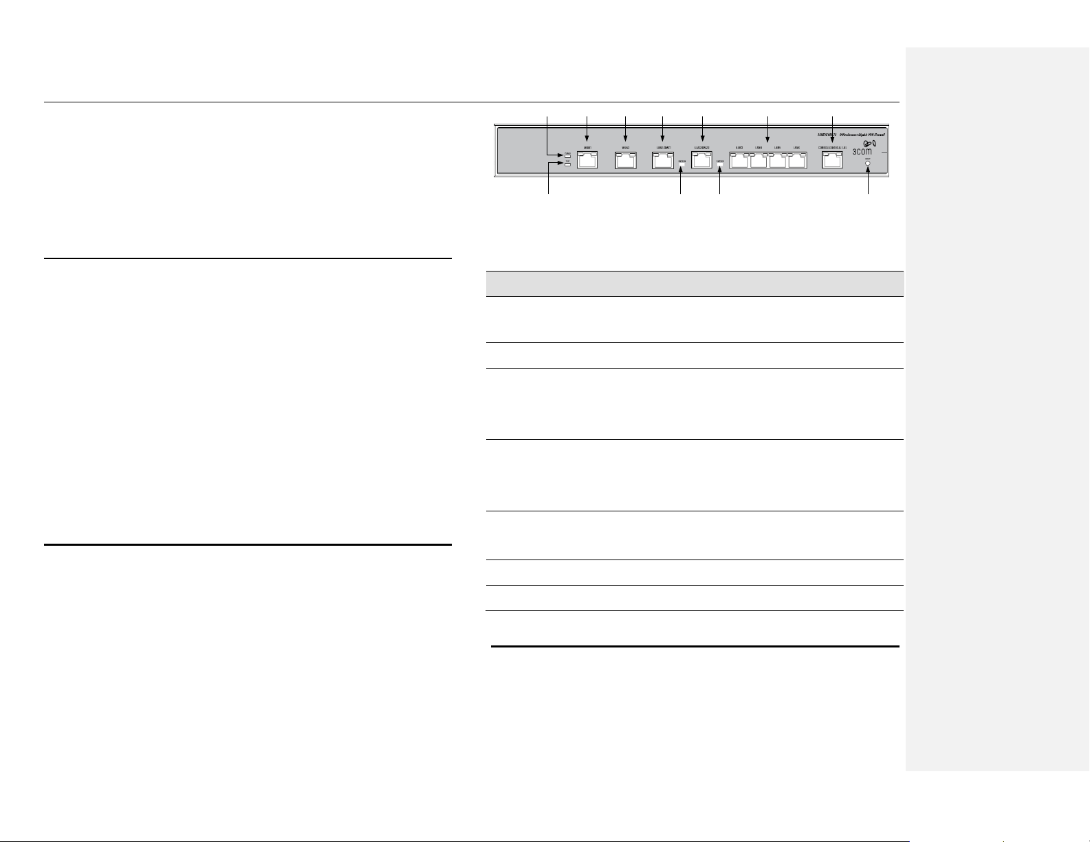
2.2 Front Panel
The front panel contains LED indicators that show the status of the unit and the
ports for the data connections.
WAN1 WAN2
LAN1/DMZ1 LAN2/DMZ2
POWER
TEST LED
LAN3 ~ LAN6 CONSOLE
Reset
DMZ2 LEDDMZ1 LED
Figure 2.1 Front Panel LEDs
Table 2.1 Front Panel Label and LEDs
Label
Color
Function
POWER
Green
On: Unit is powered on
Off: Unit is powered off
STATUS
Amber
(For factory testing only)
Link/Act
Green
Green: Link is established
Flashing: Data is transmitted
Off: No Link
1000
Green/Amber
Green: Gigabit link
Amber: 100M link
Off: 10M link or no link
DMZ
Green
Green: This port is used as DMZ port
Off: This port is used as LAN port
CONSOLE
RJ-45 serial port for console management
Reset
Resets the device
2.3 Rear Panel
The rear panel contains the AC inlet and power switch. See Figure 2.2 Rear
Panel Connections.
Page 18
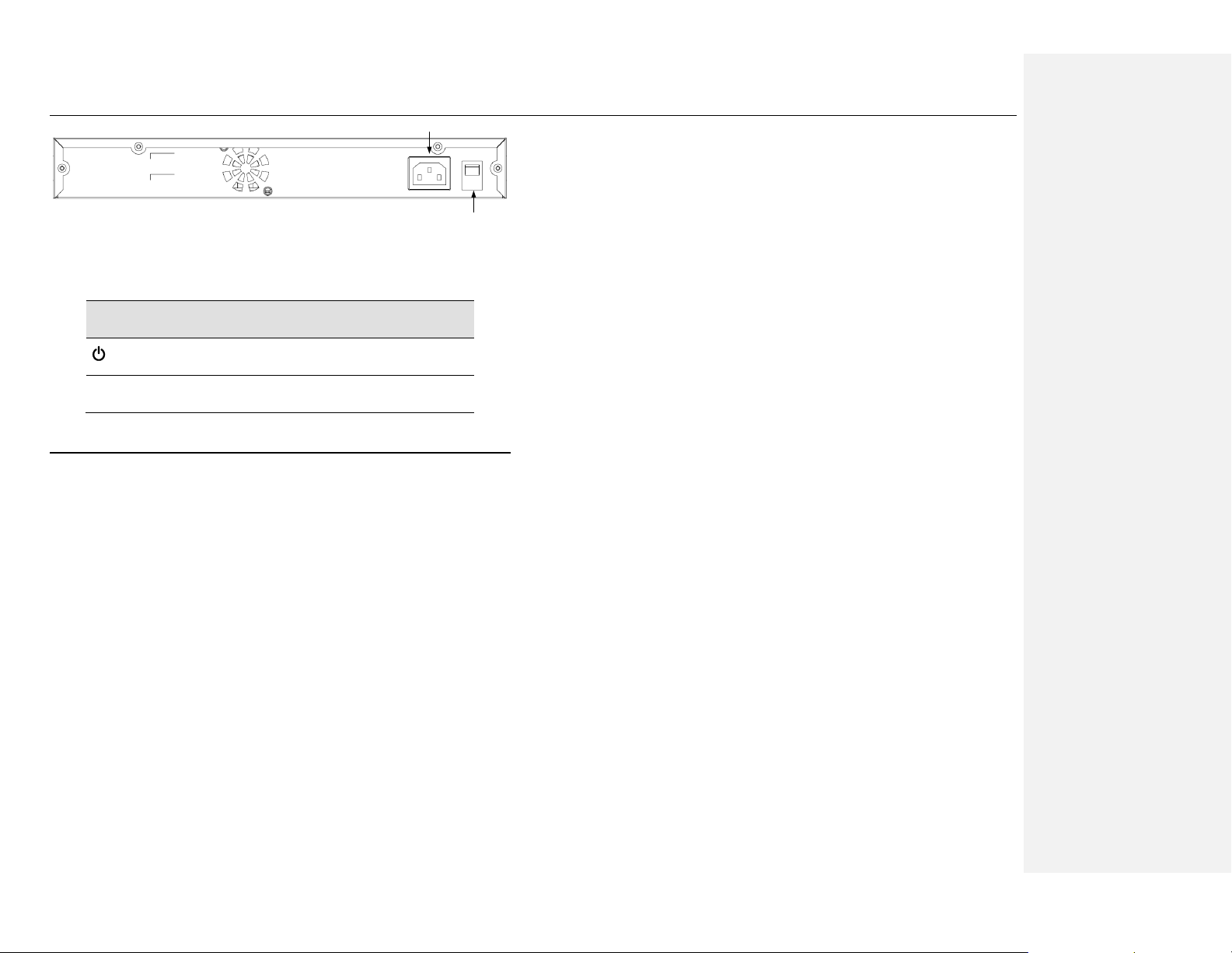
Chapter 2. Getting to Know the OfficeConnect Gigabit VPN Firewall OfficeConnect VPN Firewall User’s Manual
4
Power Switch
AC Inlet
Figure 2.2 Rear Panel Connections
Table 2.2 Rear Panel Labels and LEDs
Label
Function
Switches the unit on and off
POWER
Connects to the supplied power adapter
2.4 Major Features
2.4.1 Firewall Features
The Firewall as implemented in the OfficeConnect Gigabit VPN Firewall provides
the following features to protect your network from being attacked and to prevent
your network from being used as the springboard for attacks.
Address Sharing and Management
Packet Filtering
Stateful Packet Inspection
Defense against Denial of Service Attacks
Application Content Filtering
Log and Alert
Remote Access
Keyword based Content filtering
WAN Failover & Load Balancing
2.4.1.1 Address Sharing and Management
The OfficeConnect Gigabit VPN Firewall provides NAT to share a single highspeed Internet connection and to save the cost of multiple connections required
for the hosts on the LAN segments connected to the OfficeConnect Gigabit VPN
Firewall. This feature conceals network address and prevents them from
becoming public. It maps unregistered IP addresses of hosts connected to the
LAN with valid ones for Internet access. The OfficeConnect Gigabit VPN Firewall
also provides reverse NAT capability, which enables SOHO users to host
various services such as e-mail servers, web servers, etc. The NAT rules drive
the translation mechanism at the NAT router.
2.4.1.1 ACL (Access Control List)
ACL rule is one of the basic building blocks for network security. Firewall
monitors each individual packet, decodes the header information of inbound and
outbound traffic and then either blocks the packet from passing or allows it to
pass based on the contents of the source address, destination address, source
port, destination port, protocol and other criterion, e.g. application filter,
Schedules, defined in the ACL rules.
ACL is a very appropriate measure for providing isolation of one subnet from
another. It can be used as the first line of defense in the network to block
inbound packets of specific types from ever reaching the protected network.
The OfficeConnect Gigabit VPN Firewall’s ACL methodology supports:
Filtering based on destination and source IP address, port number and
protocol
Filter Rule priorities
Time based filters
Page 19

OfficeConnect VPN Firewall User’s Manual Chapter 2 Getting to Know the OfficeConnect Gigabit VPN Firewall
5
Application specific filters
2.4.1.2 Stateful Packet Inspection
The OfficeConnect Gigabit VPN Firewall uses ―stateful packet inspection‖ that
extracts state-related information required for the security decision from the
packet and maintains this information for evaluating subsequent connection
attempts. It has awareness of application and creates dynamic sessions that
allow dynamic connections so that no ports need to be opened other than the
required ones. This provides a solution which is highly secure and that offers
scalability and extensibility.
2.4.1.3 Defense against DoS Attacks
The OfficeConnect Gigabit VPN Firewall has an Attack Defense Engine that
protects internal networks from known types of Internet attacks. It provides
automatic protection from Denial of Service (DoS) attacks such as SYN flooding,
IP smurfing, LAND, Ping of Death and all re-assembly attacks. It can drop ICMP
redirects and IP loose/strict source routing packets. For example, the
OfficeConnect Gigabit VPN Firewall provides protection from ―WinNuke‖, a
widely used program to remotely crash unprotected Windows systems in the
Internet. The OfficeConnect Gigabit VPN Firewall also provides protection from a
variety of common Internet attacks such as IP Spoofing, Ping of Death, Land
Attack, Reassembly and SYN flooding.
The type of attack protections provided by the OfficeConnect Gigabit VPN
Firewall are listed in Table 2.3.
Table 2.3 DoS Attacks
Type of Attack
Name of Attacks
Re-assembly attacks
Bonk, Boink, Teardrop (New Tear),
Overdrop, Opentear, Syndrop, Jolt
ICMP Attacks
Ping of Death, Smurf, Twinge
Flooders
ICMP Flooder, UDP Flooder, SYN
Flooder
Port Scans
TCP XMAS Scan, TCP Null Scan
TCP SYN Scan, TCP Stealth Scan
TCP Attacks
TCP sequence number prediction, TCP
out-of sequence attacks
Protection with PF Rules
Echo-Chargen, Ascend Kill
Miscellaneous Attacks
IP Spoofing, LAND, Targa, Tentacle
MIME Flood, Winnuke, FTP Bounce, IP
unaligned time stamp attack
2.4.1.4 Application Command Filtering
The OfficeConnect Gigabit VPN Firewall allows network administrators to block,
monitor, and report on network users access to non-business and objectionable
content. This high-performance content access control results in increased
productivity, lower bandwidth usage and reduced legal liability.
The OfficeConnect Gigabit VPN Firewall has the ability to handle active content
filtering on certain application protocols such as HTTP, FTP, SMTP and RPC.
HTTP – You can define HTTP extension based filtering schemes for
blocking
ActiveX
Java Archive
Java Applets
URLs based on file extensions.
Page 20

Chapter 2. Getting to Know the OfficeConnect Gigabit VPN Firewall OfficeConnect VPN Firewall User’s Manual
6
2.4.1.5 Application Level Gateway (ALG)
Applications such as FTP, games etc., open connections dynamically based on
the respective application parameter. To go through the firewall on the
OfficeConnect Gigabit VPN Firewall, packets pertaining to an application, require
a corresponding allow rule. In the absence of such rules, the packets will be
dropped by the OfficeConnect Gigabit VPN Firewall. As it is not feasible to
create policies for numerous applications dynamically (at the same time without
compromising security), intelligence in the form of Application Level Gateways
(ALG), is built to parse packets for applications and open dynamic associations.
The OfficeConnect Gigabit VPN Firewall provides a number of ALGs for popular
applications such as FTP, H.323, RTSP, SIP, etc.
2.4.1.6 Local Content Filtering
A set of keywords that should not appear in the URL (Uniform Resource Locator,
e.g. www.yahoo.com) can be defined. Any URL containing one or more of these
keywords will be blocked. This is a policy independent feature i.e. it cannot be
associated to ACL rules. This feature can be independently enabled or disabled,
but works only if firewall is enabled.
2.4.1.7 Log and Alerts
Events in the network, that could be attempts to affect its security, are recorded
in the OfficeConnect Gigabit VPN Firewall System log file. Event details are
recorded in WELF (WebTrends Enhanced Log Format ) format so that statistical
tools can be used to generate custom reports. The OfficeConnect Gigabit VPN
Firewall can also forward Syslog information to a Syslog server on a private
network.
The OfficeConnect Gigabit VPN Firewall supports:
Alerts sent to the administrator via e-mail.
Maintains at a minimum, log details such as, time of packet arrival,
description of action taken by Firewall and reason for action.
Supports the UNIX Syslog format.
Sends log report e-mails as scheduled by the network administrator or by
default when the log file is full.
All the messages are sent in the WELF format.
ICMP logging to show code and type.
2.4.2 VPN
The introduction of broadband Internet access at an affordable price has
attracted a large number of users to use the Internet for business. Large-scale
use of a very open public network such as, the Internet comes with a lot of
advantages and associated risks. These risks include the lack of confidentiality
of data being sent and the authenticity of the identities of the parties involved in
the exchange of data. The VPN supported in the OfficeConnect Gigabit VPN
Firewall is intended to resolve these issues at an affordable price.
The VPN supported by the OfficeConnect Gigabit VPN Firewall is IPSec
compliant. Packets sent via VPN are encrypted to maintain privacy. The
encrypted packets are then tunneled through a public network. As a result,
tunnel participants enjoy the same security features and facilities that are
available only to members of private networks at a reduced cost.
The following table lists the VPN features supported by the OfficeConnect
Gigabit VPN Firewall:
Table 2.4 VPN Features of the OfficeConnect Gigabit VPN Firewall
Features
Transport Mode for Client-Client Connectivity
Page 21

OfficeConnect VPN Firewall User’s Manual Chapter 2 Getting to Know the OfficeConnect Gigabit VPN Firewall
7
Tunnel Mode for Network-Network Connectivity
IP Fragmentation and Reassembly
IPSec
Support
Hardware Encryption Algorithm
DES, 3DES, AES
Hardware Authentication Algorithm
MD5, SHA-1
Transforms
ESP, AH
Key Management
IKE , IKEv2
Mode configuration for IKE
Main Mode, Aggressive Mode, Quick
Mode
Site-to-Site VPN connection – Site-to-Site VPN connection is an alternative
WAN infrastructure that is used to connect branch offices, home offices, or
business partners’ sites to all or portions of a company’s network.
Remote Access VPN – Corporations use VPN to establish secure, end-to -
end private network connections over a public networking infrastructure.
VPN have become the logical solution for remote access connectivity.
Deploying a remote access VPN enables corporations to reduce
communications expenses by leveraging the local dial-up infrastructure of
Internet Service Providers. At the same time, VPNs allow mobile workers,
telecommuters and day extenders to take advantage of broadband
connectivity.
2.4.3 WAN Failover & Load Balancing
WAN Failover and Load Balancing allows you to designate the one of the
assigned interfaces as a backup WAN port. If the primary WAN port is down
and/or unavailable, traffic is only routed through the backup WAN port. This
allows OfficeConnect Gigabit VPN Firewall to maintain a persistent connection
for WAN port traffic by failing over to the backup WAN port.
The primary and secondary WAN ports can also be used in a more dynamic
setup, where the administrator can choose a method of dividing outbound traffic
flows between the two WAN ports. This feature is referred to as load balancing.
2.4.4 QoS and Bandwidth Management
QoS and Bandwidth Management function allows voice and data traffic to flow
through where voice traffic is transmitted in the highest priority. With DiffServ
QoS enabled, it guarantees voice packets to have first priority to pass through a
DiffServ QoS enabled devices such as router or switch.
2.4.5 Virtual LAN Interfaces (VLAN)
The Virtual Local Area Network (VLAN) feature allows OfficeConnect Gigabit
VPN Firewall to be partitioned into non-interacting network domains.
Page 22

Page 23
OfficeConnect VPN Firewall User’s Manual Chapter 3. Quick Start Guide
9
3 Quick Start Guide
This Quick Start Guide provides basic instructions for connecting the
OfficeConnect Gigabit VPN Firewall to a computer or a LAN and to the Internet.
Part 1 provides instructions to set up the hardware.
Part 2 describes how to configure Internet properties on your computer(s).
Part 3 shows you how to configure basic settings on the OfficeConnect
Gigabit VPN Firewall to get your LAN connected to the Internet.
After setting up and configuring the device, you can follow the instructions on
page 18 to verify that it is working properly.
This Quick Start Guide assumes that you have already established ADSL or
cable modem service with your Internet service provider (ISP). These
instructions provide a basic configuration that should be compatible with your
home or small office network setup. Refer to the subsequent chapters for
additional configuration instructions.
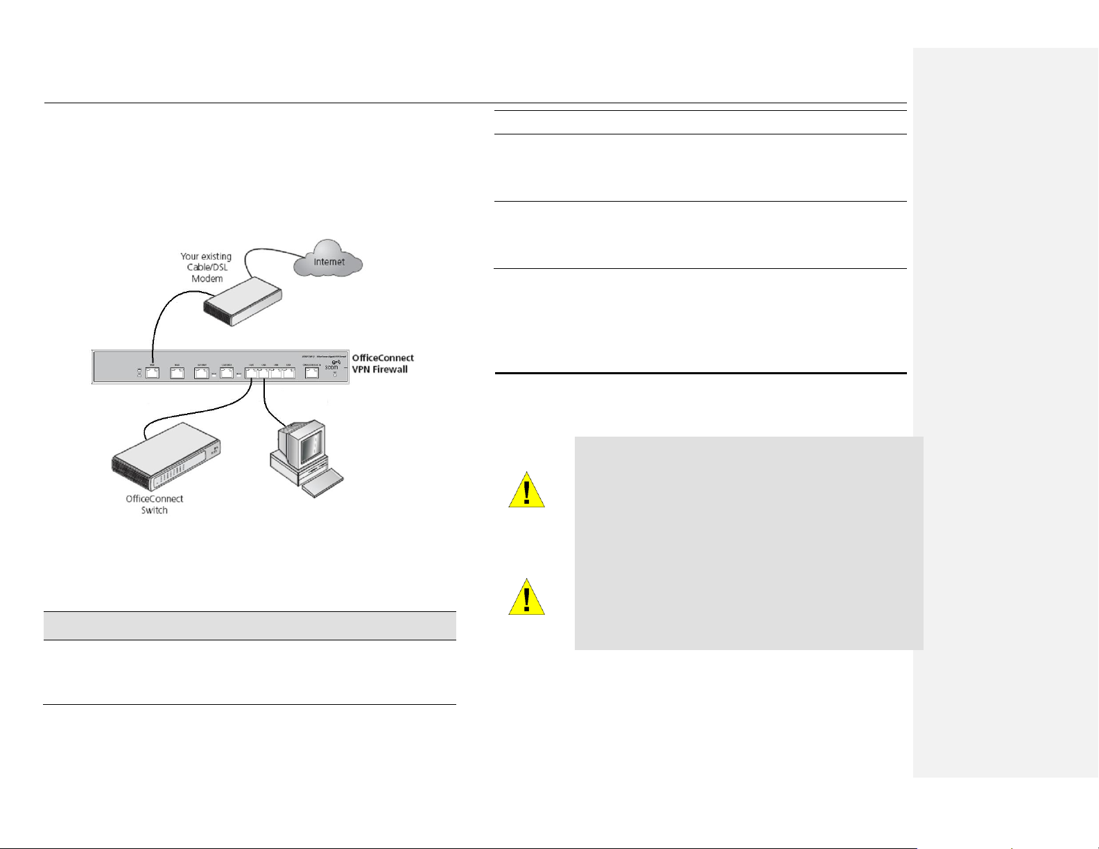
3.1 Part 1 — Connecting the Hardware
In Part 1, you connect the device to an ADSL or a cable modem (which in turn is
connected to a phone jack or a cable outlet), the power outlet, and your
computer or network.
WARNING
Before you begin, turn the power off for all devices. These
include your computer(s), your LAN hub/switch (if applicable),
and the OfficeConnect Gigabit VPN Firewall.
WARNING
RISK OF EXPLOSION IF BATTERY IS REPLACED BY AN
INCORRECT TYPE. DISPOSE OF USED BATTERIES
ACCORDING TO THE INSTRUCTIONS
Figure 3.1 illustrates the hardware connections. Please follow the steps that
follow for specific instructions.
3.1.1 Step 1. Connect an ADSL or a cable modem.
For the OfficeConnect Gigabit VPN Firewall: Connect one end of the Ethernet
cable to the port labeled WAN on the front panel of the device. Connect the other
end to the Ethernet port on the ADSL or cable modem.
3.1.2 Step 2. Connect computers or a LAN.
If your LAN has no more than 6 computers, you can use an Ethernet cable to
connect computers directly to the built-in switch on the device. Note that you
should attach one end of the Ethernet cable to any of the port labeled LAN1 –
LAN6 on the front panel of the device and connect the other end to the Ethernet
port of a computer.
If your LAN has more than 6 computers, you can attach one end of an Ethernet
cable to a hub or a switch (probably an uplink port; please refer to the hub or
switch documentations for instructions) and the other to the Ethernet switch port
(labeled LAN1 – LAN6) on the OfficeConnect Gigabit VPN Firewall.
Note that either the crossover or straight-through Ethernet cable can be used to
connect the built-in switch and computers, hubs or switches as the built-in switch
is smart enough to make connections with either type of cables.
3.1.3 Step 3. Attach the power adapter.
Connect the AC power adapter to the POWER connector on the back of the
device and plug in the adapter to a wall outlet or a power strip.
Page 24
Chapter 3. Quick Start Guide OfficeConnect Gigabit VPN Firewall User’s Manual
10
3.1.4 Step 4. Turn on the OfficeConnect Gigabit VPN
Firewall, the ADSL or cable modem and power up
your computers.
Press the Power switch on the rear panel of the OfficeConnect Gigabit VPN
Firewall to the ON position. Turn on your ADSL or cable modem. Turn on and
boot up your computer(s) and any LAN devices such as hubs or switches.
Figure 3.1 Overview of Hardware Connections
You should verify that th e LEDs are illuminated as indicated in Table 3.1.
Table 3.1 LED Indicators
This LED:
...should be:
POWER
Solid green to indicate that the device is turned on. If this light
is not on, check if the power adapter is attached to the
OfficeConnect Gigabit VPN Firewall and if it is plugged into a
power source.
LAN1 –
LAN6
Solid green to indicate that the device can communicate with
your LAN or flashing when the device is sending or receiving
data from your LAN computer.
WAN1 –
WAN2
Solid green to indicate that the device has successfully
established a connection with your ISP or flashing when the
device is sending or receiving data from the Internet.
If the LEDs illuminate as expected, the OfficeConnect Gigabit VPN Firewall
hardware is working properly.
3.2 Part 2 — Rack Mounting Instructions
The OfficeConnect Gigabit VPN Firewall is 1U high and will fit a 19-inch rack if
the rack mount kit is properly installed.
WARNING
Elevated Operating Ambient - If installed in a closed or multiunit rack assembly, the operating ambient temperature of the
rack environment may be greater than room ambient. Therefore,
consideration should be given to installing the equipment in an
environment compatible with the maximum ambient temperature
(Tma) specified by the manufacturer.
WARNING
Reduced Air Flow - Installation of the equipment in a rack
should be such that the amount of air flow required for safe
operation of the equipment is not compromised.
Page 25
OfficeConnect Gigabit VPN Firewall User’s Manual Chapter 3. Quick Start Guide
11
WARNING
Mechanical Loading - Mounting of the equipment in the rack
should be such that a hazardous condition is not achieved due to
uneven mechanical loading.
WARNING
Circuit Overloading - Consideration should be given to the
connection of the equipment to the supply circuit and the effect
that overloading of the circuits might have on overcurrent
protection and supply wiring. Appropriate consideration of
equipment nameplate ratings should be used when addressing
this concern.
WARNING
Reliable Earthing - Reliable earthing of rack-mounted equipment
should be maintained. Particular attention should be given to
supply connections other than direct connections to the branch
circuit (e.g. use of power strips).
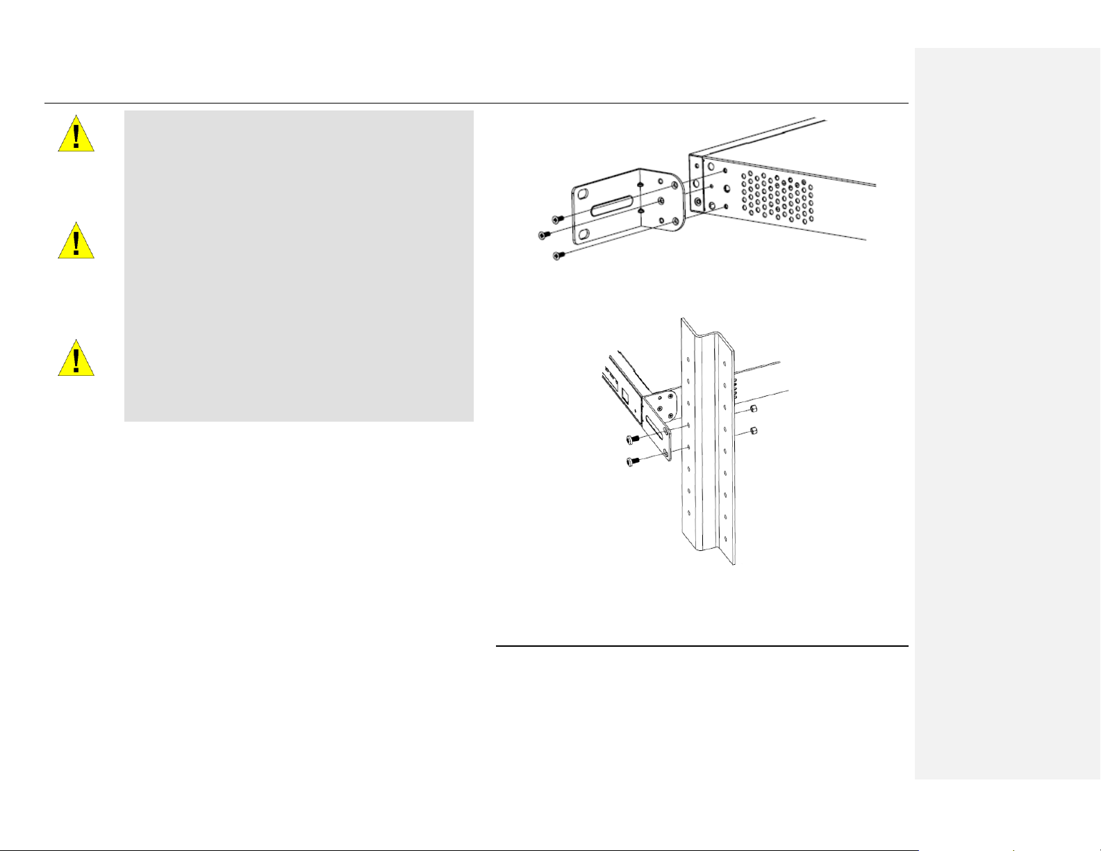
Follow these instructions to install OfficeConnect Gigabit VPN Firewall to your
19-inch rack:
1. Place the unit the right way up on a hard, flat surface with the front
facing towards you.
2. Locate a mounting bracket over the mounting holes on one side of
the unit, as shown in Figure 3.2 below.
3. Insert the two screws and fully tighten with a suitable screwdriver.
4. Repeat the two previous steps for the other side of the unit.
5. Insert the unit into the 19-inch rack and secure with suitable screws
(not provided).
6. Reconnect all cables.
Figure 3.2 Assembling the rack mount kit
Figure 3.3 Rack Mounting
3.3 Part 3 — Configuring Your Computers
Part 3 of the Quick Start Guide provides instructions for configuring the Internet
settings on your computers to work with the OfficeConnect Gigabit VPN Firewall.
Page 26

Chapter 3. Quick Start Guide OfficeConnect Gigabit VPN Firewall User’s Manual
12
3.3.1 Before you begin
By default, the OfficeConnect Gigabit VPN Firewall automatically assigns all
required Internet settings to your PCs. You need only to configure the PCs to
accept the information when it is assigned.
Note
In some cases, you may want to configure network settings
manually to some or all of your computers rather than allow the
OfficeConnect Gigabit VPN Firewall to do so. See “Assigning static
IP addresses to your PCs” in page 14 for instructions.
If you have connected your PC via Ethernet to the OfficeConnect Gigabit
VPN Firewall, follow the instructions that correspond to the operating
system installed on your PC.
3.3.2 Windows® XP PCs:
1. In the Windows task bar, click the <Start> button, and then click
Control Panel.
2. Double-click the Network Connections icon.
3. In the LAN or High-Speed Internet window, right-click on icon
corresponding to your network interface card (NIC) and select
Properties. (Often this icon is labeled Local Area Connection).
The Local Area Connection dialog box displays with a list of currently
installed network items.
4. Ensure that the check box to the left of the item labeled Internet
Protocol TCP/IP is checked, and click <Properties> button.
5. In the Internet Protocol (TCP/IP) Properties dialog box, click the
radio button labeled Obtain an IP address automatically. Also click
the radio button labeled Obtain DNS server address
automatically.
6. Click <OK> button twice to confirm your changes, and close the
Control Panel.
3.3.3 Windows® 2000 PCs:
First, check for the IP protocol and, if necessary, install it:
1. In the Windows task bar, click the <Start> button, point to Settings,
and then click Control Panel.
2. Double-click the Network and Dial-up Connections icon.
3. In the Network and Dial-up Connections window, right-click the
Local Area Connection icon, and then select Properties.
The Local Area Connection Properties dialog box displays a list of
currently installed network components. If the list includes Internet
Protocol (TCP/IP), then the protocol has already been enabled. Skip
to step 10.
4. If Internet Protocol (TCP/IP) does not display as an installed
component, click <Install> button.
5. In the Select Network Component Type dialog box, select Protocol,
and then click <Add> button.
6. Select Internet Protocol (TCP/IP) in the Network Protocols list, and
then click <OK> button.
You may be prompted to install files from your Windows 2000
installation CD or other media. Follow the instructions to install the
files.
7. If prompted, click <OK> button to restart your computer with the new
settings.
Next, configure the PCs to accept IP addresses assigned by the
OfficeConnect Gigabit VPN Firewall:
8. In the Control Panel, double-click the Network and Dial-up
Connections icon.
9. In Network and Dial-up Connections window, right-click the Local
Area Connection icon, and then select Properties.
Page 27

OfficeConnect Gigabit VPN Firewall User’s Manual Chapter 3. Quick Start Guide
13
10. In the Local Area Connection Properties dialog box, select Internet
Protocol (TCP/IP), and then click <Properties> button.
11. In the Internet Protocol (TCP/IP) Properties dialog box, click the
radio button labeled Obtain an IP address automatically. Also click
the radio button labeled Obtain DNS server address
automatically.
12. Click <OK> button twice to confirm and save your changes, and then
close the Control Panel.
3.3.4 Windows® 95, 98, and Me PCs
1. In the Windows task bar, click the <Start> button, point to Settings,
and then click Control Panel.
2. Double-click the Network icon.
In the Network dialog box, look for an entry started w/ ―TCP/IP ‖
and the name of your network adapter, and then click <Properties>
button. You may have to scroll down the list to find this entry. If the list
includes such an entry, then the TCP/IP protocol has already been
enabled. Skip to step 8.
3. If Internet Protocol (TCP/IP) does not display as an installed
component, click <Add> button.
4. In the Select Network Component Type dialog box, select Protocol,
and then click <Add> button.
5. Select Microsoft in the Manufacturers list box, and then click TCP/IP
in the Network Protocols list, box and then click <OK> button.
You may be prompted to install files from your Windows 95, 98 or Me
installation CD or other media. Follow the instructions to install the
files.
6. If prompted, click <OK> button to restart your computer with the new
settings.
Next, configure the PCs to accept IP information assigned by the
OfficeConnect Gigabit VPN Firewall:
7. In the Control Panel, double-click the Network icon.
8. In the Network dialog box, select an entry started with ―TCP/IP ”
and the name of your network adapter, and then click <Properties>
button.
9. In the TCP/IP Properties dialog box, click the radio button labeled
Obtain an IP address automatically.
10. In the TCP/IP Properties dialog box, click the ―Default Gateway‖ tab.
Enter 192.168.1.1 (the default LAN port IP address of the
OfficeConnect Gigabit VPN Firewall) in the ―New gateway‖ address
field and click <Add> button to add the default gateway entry.
11. Click <OK> button twice to confirm and save your changes, and then
close the Control Panel.
12. If prompted to restart your computer, click <OK> button to do so with
the new settings.
3.3.5 Windows® NT 4.0 workstations:
First, check for the IP protocol and, if necessary, install it:
1. In the Windows NT task bar, click the <Start> button, point to
Settings, and then click Control Panel.
7. In the Control Panel window, double click the Network icon.
8. In the Network dialog box, click the Protocols tab.
The Protocols tab displays a list of currently installed network
protocols. If the list includes TCP/IP Protocol, then the protocol has
already been enabled. Skip to step 14.
9. If TCP/IP does not display as an installed component, click <Add>
button.
10. In the Select Network Protocol dialog box, select TCP/IP, and then
click <OK> button.
You may be prompted to install files from your Windows NT
installation CD or other media. Follow the instructions to install the
files.
Page 28
Chapter 3. Quick Start Guide OfficeConnect Gigabit VPN Firewall User’s Manual
14
After all files are installed, a window displays to inform you that a
TCP/IP service called DHCP can be set up to dynamically assign IP
information.
11. Click <Yes> button to continue, and then click <OK> button if
prompted to restart your computer.
Next, configure the PCs to accept IP addresses assigned by the
OfficeConnect Gigabit VPN Firewall:
12. Open the Control Panel window, and then double-click the Network
icon.
13. In the Network dialog box, click the Protocols tab.
14. In the Protocols tab, select TCP/IP, and then click <Properties>
button.
15. In the Microsoft TCP/IP Properties dialog box, click the radio button
labeled Obtain an IP address from a DHCP server.
16. Click <OK> button twice to confirm and save your changes, and then
close the Control Panel.
3.3.6 Assigning static IP addresses to your PCs
In some cases, you may want to assign IP addresses to some or all of your PCs
directly (often called ―statically‖), rather than allowing the OfficeConnect Gigabit
VPN Firewall to assign them. This option may be desirable (but not required) if:
You have obtained one or more public IP addresses that you want to
always associate with specific computers (for example, if you are using a
computer as a public web server).
You maintain different subnets on your LAN.
However, during the first time configuration of your OfficeConnect Gigabit VPN
Firewall, you must assign an IP address in the 192.168.1.0 network for your PC,
say 192.168.1.2, in order to establish connection between the OfficeConnect
Gigabit VPN Firewall and your PC as the default LAN IP on OfficeConnect
Gigabit VPN Firewall is pre-configured as 192.168.1.1. Enter 255.255.255.0 for
the subnet mask and 192.168.1.1 for the default gateway. These settings may
be changed later to reflect your true network environment.
On each PC to which you want to assign static information, follow the
instructions on pages 12 through 13 relating only to checking for and/or installing
the IP protocol. Once it is installed, continue to follow the instructions for
displaying each of the Internet Protocol (TCP/IP) properties. Instead of enabling
dynamic assignment of the IP addresses for the computer, DNS server, and
default gateway, click the radio buttons that enable you to enter the information
manually.
Note
Your PCs must have IP addresses that place them in the same
subnet as the OfficeConnect Gigabit VPN Firewall’s LAN port. If you
manually assign IP information to all your LAN PCs, you can follow
the instructions in Chapter 5 to change the LAN port IP address
accordingly.
3.4 Part 4 — Quick Configuration of the
OfficeConnect Gigabit VPN Firewall
In Part 4, you log into the Configuration Manager on the OfficeConnect Gigabit
VPN Firewall and configure basic settings for your Internet connection. Your ISP
should provide you with the necessary information to complete this step. Note
the intent here is to quickly get the OfficeConnect Gigabit VPN Firewall up and
running, instructions are concise. You may refer to corresponding chapters for
more details.
3.4.1 Setting Up the OfficeConnect Gigabit VPN Firewall
Follow these instructions to setup the OfficeConnect Gigabit VPN Firewall:
1. Before accessing the Configuration Manager in the OfficeConnect
Gigabit VPN Firewall, make sure that the HTTP proxy setting is
Page 29
OfficeConnect Gigabit VPN Firewall User’s Manual Chapter 3. Quick Start Guide
15
disabled in your browser. In IE, click ―Tools‖ ―Internet Options…‖
―Connections‖ tab ―LAN settings…‖ and then uncheck ―Use
proxy server for your LAN …‖
2. On any PC connected to one of the four LAN ports on the
OfficeConnect Gigabit VPN Firewall, open your Web browser, and
type the following URL in the address/location box, and press
<Enter>:
http://192.168.1.1
This is the predefined IP address for the LAN port on the OfficeConnect
Gigabit VPN Firewall.
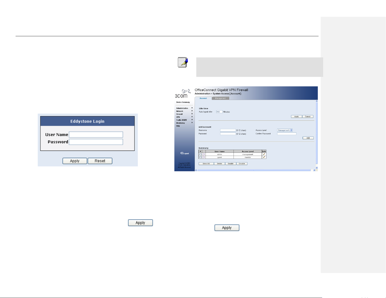
A login screen displays, as shown in Figure 3.4.
Figure 3.4 Login Screen
If you have problem connecting to the OfficeConnect Gigabit VPN
Firewall, you may want to check if your PC is configured to accept IP
address assignment from the OfficeConnect Gigabit VPN Firewall.
Another method is to set the IP address of your PC to any IP address in
the 192.168.1.0 network, such as 192.168.1.2.
3. Enter your user name and password, and then click to
enter the Configuration Manager. The first time you log into this
program, use these defaults:
Default User Name:
admin
Default Password:
password
Note
You can change the password at any time.
Figure 3.5 System Access Configuration Page
4. Click on Administration System Access menu to enter Account
configuration page as shown in Figure 3.5. Select an appropriate
account and change the password in the spaces provided if desired.
When changing passwords, make sure you enter the existing login
password in the Old Password field, enter the new password in New
Password field and confirm the new password in Retype New Password
field and click button to save the change
Page 30
Chapter 3. Quick Start Guide OfficeConnect Gigabit VPN Firewall User’s Manual
16
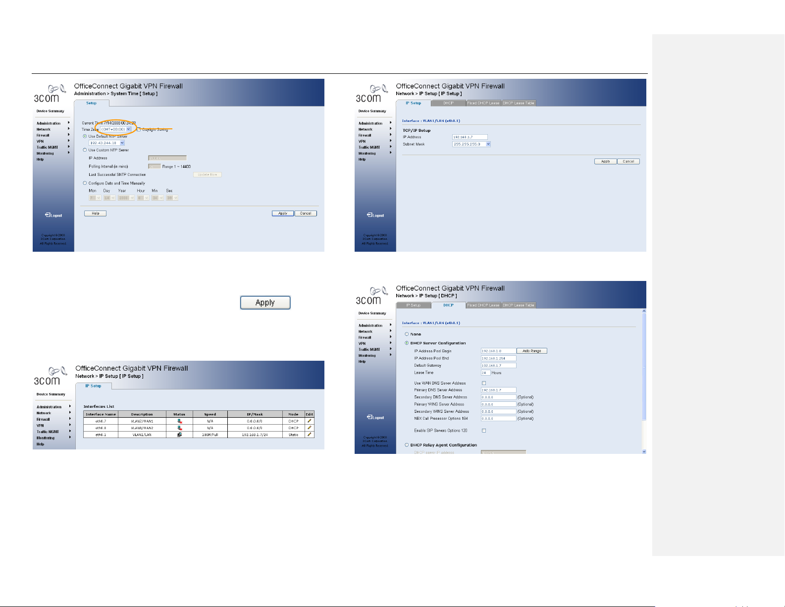
Figure 3.6 System Time Configuration Page
5. Click on Administration System Time menu and set the time zone
for the OfficeConnect Gigabit VPN Firewall by selecting your time
zone from the Time Zone drop-down list. Click to save
the settings.
6. It is recommended that you keep the default LAN IP settings at this
point until after you have completed the rest of the configurations
and confirm that your Internet connection is working.
Figure 3.7 IP Setup Configuration Page
Figure 3.8 DHCP Server Configuration Page
Time Zone
drop-down
Page 31

OfficeConnect Gigabit VPN Firewall User’s Manual Chapter 3. Quick Start Guide
17
7. It is recommended that you keep the default settings for DHCP
server until after you have completed the rest of the configurations
and confirm that your Internet connection is working.
8. Click on Network IP Setup to configure the WAN settings for the
OfficeConnect Gigabit VPN Firewall.
Figure 3.9 WAN PPPoE Configuration Page
Figure 3.10 WAN Dynamic IP Configuration Page
a) PPPoE Connection Mode (see Figure 3.9)
Tick the Login Required checkbox.
Enter the user name and password provided by your ISP.
Click on the PPPoE radio button.
AC Name and Service Name are optional. You may leave it
empty if your ISP did not provide such information.
Tick the Disconnect checkbox if you want to disconnect the
PPPoE interface after the assigned idle timeout period has
elapsed.
Tick the Unnumbered checkbox to enable the PPP
unnumbered function.
You don’t need to enter primary/secondary DNS IP
addresses as PPPoE is able to automatically obtain this
information for you from your ISP. However, if you prefer to
use your favorite DNS servers, you may enter them in the
space provided.
Click on button to save the PPPoE settings.
Page 32

Chapter 3. Quick Start Guide OfficeConnect Gigabit VPN Firewall User’s Manual
18
b) Dynamic IP Connection Mode (see Figure 3.10)
Select the DHCP radio button to enable the DHCP function.
You don’t need to enter primary/secondary DNS IP
addresses as DHCP client is able to automatically obtain this
information for you from your ISP. However, if you prefer to
use your favorite DNS servers, you may enter them in the
space provided.
If you had previously registered a specific MAC address with
your ISP for Internet connections, enter the registered MAC
address here and make sure you check the MAC cloning
check box.
Click on button to save the dynamic IP
settings.
Figure 3.11 WAN Static IP Configuration Page
c) Static IP Connection Mode
Enter WAN IP address in the IP Address field. This
information should be provided by your ISP.
Enter IP Subnet Mask for the WAN. This information should
be provided by your ISP. Typically, it is 255.255.255.0.
Enter Gateway IP address provided by your ISP in the space
provided.
Enter at lease the primary DNS IP address provided by your
ISP. Secondary DNS IP address is optional. Enter it in the
space provided if you have such information from your ISP.
Click to save the static IP settings
You have now completed customizing basic configuration settings. Read the
following section to determine if you have access to the Internet.
3.4.2 Testing Your Setup
At this point, the OfficeConnect Gigabit VPN Firewall should enable any
computer on your LAN to use the OfficeConnect Gigabit VPN Firewall’s ADSL or
cable modem connection to access the Internet.
To test the Internet connection, open your web browser, and type the URL of
any external website (such as http://www.3com.com). The LED labeled WAN
should be blinking rapidly and may appear solid as the device connects to the
site. You should also be able to browse the web site through your web browser.
If the LEDs do not illuminate as expected or the web page does not display, see
Appendix 20 for troubleshooting suggestions.
3.4.3 Default Router Settings
In addition to handling the DSL connection to your ISP, the OfficeConnect
Gigabit VPN Firewall can provide a variety of services to your network. The
device is pre-configured with default settings for use with a typical home or small
office network.
Page 33

OfficeConnect Gigabit VPN Firewall User’s Manual Chapter 3. Quick Start Guide
19
Table 3.2 lists some of the most important default settings; these and other
features are described fully in the subsequent chapters. If you are familiar with
network configuration settings, review the settings in Table 3.2 to verify that they
meet the needs of your network. Follow the instructions to change them if
necessary. If you are unfamiliar with these settings, try using the device without
modification, or contact your ISP for assistance.
Before you modifying any settings, review Chapter 4 for general information
about accessing and using the Configuration Manager program. We strongly
recommend that you contact your ISP prior to changing the default configuration.
Table 3.2 Default Settings Summary
Option
Default Setting
Explanation/Instructions
DHCP (Dynamic
Host Configuration
Protocol)
DHCP server enabled
with the following pool
of addresses:
192.168.1.2 through
192.168.1.254
The OfficeConnect Gigabit
VPN Firewall maintains a pool
of private IP addresses for
dynamic assignment to your
LAN computers. To use this
service, you must have set up
your computers to accept IP
information dynamically, as
described in Part 2 of the
Quick Start Guide. See section
5.2 for an explanation of the
DHCP service.
Option
Default Setting
Explanation/Instructions
LAN Port IP
Address
Static IP address:
192.168.1.1
subnet mask:
255.255.255.0
This is the IP address of the
LAN port on the OfficeConnect
Gigabit VPN Firewall. The
LAN port connects the device
to your Ethernet network.
Typically, you will not need to
change this address. See
section 5.1 LAN IP Address for
instructions.
Page 34

Page 35

OfficeConnect VPN Firewall User’s Manual Chapter 4. Getting Started with the Configuration Manager
21
4 Getting Started with the
Configuration Manager
The OfficeConnect Gigabit VPN Firewall includes a preinstalled program called
the Configuration Manager, which provides an interface to the software installed
on the device. It enables you to configure the device settings to meet the needs
of your network. You access it through your web browser from any PC
connected to the OfficeConnect Gigabit VPN Firewall via the LAN or WAN ports.
This chapter describes the general guides for using the Configuration Manager.
4.1 Log into Configuration Manager
The Configuration Manager program is preinstalled on the OfficeConnect Gigabit
VPN Firewall. To access the program, you need the following:
A computer connected to the LAN or WAN port on the OfficeConnect
Gigabit VPN Firewall as described in the Quick Start Guide chapter.
A web browser installed on the computer. The program is designed to work
best with Microsoft Internet Explorer® 5.5, Netscape 7.0.2 or later.
You may access the program from any computer connected to the
OfficeConnect Gigabit VPN Firewall via the LAN or WAN ports. However, the
instructions provided here are for computers connected via the LAN ports.
1. From a LAN computer, open your web browser, type the following in
the web address (or location) box, and press <Enter>:
http://192.168.1.1
This is the predefined IP address for the LAN port on the OfficeConnect
Gigabit VPN Firewall. A login screen displays, as shown in Figure 4.1.
Figure 4.1 Configuration Manager Login Screen
2. Enter your user name and password, and then click .
The first time you log into the program, use these defaults:
Default User Name:
admin
Default Password:
password
4.2 Functional Layout
Typical Configuration Manager page consists of two separate frames. The left
frame, as shown in Figure 4.2, contains all the menus available for device
configuration. Related menus are grouped into categories, such as System,
Network and etc. You can click on any of these to display a specific configuration
page.
Page 36

Chapter 4. Getting Started with the Configuration Manager OfficeConnect VPN Firewall User’s Manual
22
Figure 4.2 Typical Configuration Manager Page
A separate page displays in the right-hand-side frame for each menu. For
example, the configuration page displayed in Figure 4.2 is intended for DHCP
configuration.
4.2.1 Commonly Used Buttons and Icons
The following buttons or icons are used throughout the application. The following
table describes the function for each button or icon.
Table 4.1 Description of Commonly Used Buttons and Icons
Button/Icon
Function
Stores any changes you have made on the current page.
Button/Icon
Function
Discards any changes you have made and reverts all fields
back to the default value.
Adds a new item into the existing configuration, e.g. a static
route or a firewall ACL rule and etc.
Deletes the selected item, e.g. a static route or a firewall
ACL rule and etc.
Selects all items from the existing configuration page.
Enables a selected item.
Disables a selected item.
Logs out from Configuration Manager.
4.3 Overview of System Configuration
To view the overall system status, log into Configuration Manager as
administrator, and then click the Device Summary menu.
Page 37

OfficeConnect VPN Firewall User’s Manual Chapter 4. Getting Started with the Configuration Manager
23
Figure 4.3 Device Summary Page
Page 38

Page 39

OfficeConnect VPN Firewall User’s Manual Chapter 5. Configuring LAN Settings
25
5 Configuring LAN Settings
This chapter describes how to configure LAN properties for the LAN interface on
the OfficeConnect Gigabit VPN Firewall that communicates with your LAN
computers. You’ll learn to configure IP address, DHCP and DNS server for your
LAN in this chapter.
5.1 LAN IP Address
If you are using the OfficeConnect Gigabit VPN Firewall with multiple PCs on
your LAN, you must connect the LAN via the Ethernet ports on the built-in
Ethernet switch. You must assign a unique IP address to each device residing
on your LAN. The LAN IP address identifies the OfficeConnect Gigabit VPN
Firewall as a node on your network; that is, its IP address must be in the same
subnet as the PCs on your LAN. The default LAN IP for the OfficeConnect
Gigabit VPN Firewall is 192.168.1.1.
Definition
A network node can be thought of as any interface where a
device connects to the network, such as the OfficeConnect Gigabit
VPN Firewall’s LAN port and the network interface cards on your
PCs. See Appendix 18 for an explanation of subnets.
You can change the default to reflect the set of IP addresses that you want to
use with your network.
Note
The OfficeConnect Gigabit VPN Firewall itself can function as a
DHCP server for your LAN computers, as described in section
5.2.3 Configuring DHCP Server, but not for its own LAN port.
5.1.1 LAN IP Configuration Parameters
Table 5.1describes the configuration parameters available for LAN IP
configuration.
Table 5.1 LAN IP Configuration Parameters
Setting
Description
IP Address
The LAN IP address of the OfficeConnect Gigabit VPN
Firewall. This IP is used by your computers to identify the
OfficeConnect Gigabit VPN Firewall’s LAN port. Note that
the public IP address assigned to you by your ISP is not
your LAN IP address. The public IP address identifies the
WAN port on the OfficeConnect Gigabit VPN Firewall to
the Internet.
Subnet Mask
The LAN subnet mask identifies which parts of the LAN IP
Address refer to your network as a whole and which parts
refer specifically to nodes on the network. Your device is
preconfigured with a default subnet mask of
255.255.255.0.
5.1.2 Configuring the LAN IP Address
Follow these steps to change the default LAN IP address.
1. Log into Configuration Manager as administrator, and then click
Network > IP Setup menu to display the Interface List Table as
shown in Figure 5.1.
2. Click on the icon of the VLAN1/LAN entry to be modified in the
Interface List Table.
Page 40

Chapter 5. Configuring LAN Settings OfficeConnect VPN Firewall User’s Manual
26
Figure 5.1 Interface List
Figure 5.2 IP Setup Configuration Page
3. In the IP Setup configuration page, enter a LAN IP address and
subnet mask for the OfficeConnect Gigabit VPN Firewall in the space
provided.
4. Click to save the LAN IP address.
If you were using an Ethernet connection for the current session, and
changed the IP address, the connection will be terminated.
5. Reconfigure your PCs, if necessary, so that their IP addresses place
them in the same subnet as the new IP address of the LAN port. See
the Quick Start Guide chapter, ―Part 3 — Configuring Your
Computers,‖ for instructions.
6. Log into Configuration Manager by typing the new IP address in your
Web browser’s address/location box.
5.2 DHCP (Dynamic Host Control Protocol)
5.2.1 What is DHCP?
DHCP is a protocol that enables network administrators to centrally manage the
assignment and distribution of IP information to computers on a network.
When you enable DHCP on a network, you allow a device — such as the
OfficeConnect Gigabit VPN Firewall — to assign temporary IP addresses to your
computers whenever they connect to your network. The assigning device is
called a DHCP server, and the receiving device is a DHCP client.
Note
If you followed the Quick Start Guide instructions, you either
configured each LAN PC with an IP address, or you specified that
it will receive IP information dynamically (automatically). If you
chose to have the information assigned dynamically, then you
configured your PCs as DHCP clients that will accept IP
addresses assigned from a DCHP server such as the
OfficeConnect Gigabit VPN Firewall.
Page 41

OfficeConnect VPN Firewall User’s Manual Chapter 5. Configuring LAN Settings
27
The DHCP server draws from a defined pool of IP addresses and ―leases‖ them
for a specified amount of time to your computers when they request an Internet
session. It monitors, collects, and redistributes the addresses as needed.
On a DHCP-enabled network, the IP information is assigned dynamically rather
than statically. A DHCP client can be assigned a different address from the pool
each time it reconnects to the network.
5.2.2 Why use DHCP?
DHCP allows you to manage and distribute IP addresses throughout your
network from the OfficeConnect Gigabit VPN Firewall. Without DHCP, you would
have to configure each computer separately with IP address and related
information. DHCP is commonly used with large networks and those that are
frequently expanded or otherwise updated.
5.2.3 Configuring DHCP Server
Note
By default, the OfficeConnect Gigabit VPN Firewall is configured
as a DHCP server on the LAN side, with a predefined IP address
pool of 192.168.1.10 through 192.168.1.42 (subnet mask
255.255.255.0). To change this range of addresses, follow the
procedures described in this section.
First, you must configure your PCs to accept DHCP information assigned by a
DHCP server:
1. Log into Configuration Manager as administrator, click the LAN
menu, and then click the DHCP submenu. The DHCP Configuration
page displays as shown in Figure 5.3:
Figure 5.3 DHCP Configuration Page
2. Enter the information for the IP Address Pool (Begin/End Address),
Subnet Mask, Lease Time and Default Gateway IP Address, fields;
others, such as Primary/Secondary DNS Server IP Address and
Primary/Secondary WINS Server IP Address are optional. However,
it is recommended that you enter the primary DNS server IP address
in the space provided. You may enter the LAN IP or your ISP’s DNS
IP in the primary DNS Server IP Address field. Table 5.2 describes
the DHCP configuration parameters in detail.
Table 5.2 DHCP Configuration Parameters
Field
Description
IP Address Pool Begin/End
Specify the lowest and highest
addresses in the DHCP address pool.
Subnet Mask
Enter the subnet mask to be used for the
DHCP address pool.
Lease Time
The amount of time the assigned
Page 42

Chapter 5. Configuring LAN Settings OfficeConnect VPN Firewall User’s Manual
28
Field
Description
address will be used by a device
connected on the LAN.
Default Gateway IP Address
The address of the default gateway for
computers that receive IP addresses
from this pool. The default gateway is
the device that the DHCP client
computers first contacted to
communicate with the Internet. Typically,
it is the OfficeConnect Gigabit VPN
Firewall’s LAN port IP address.
Primary/Secondary DNS Server
IP Address
The IP address of the Domain Name
System server to be used by computers
that receive IP addresses from this pool.
The DNS server translates common
Internet names that you type into your
web browser into their equivalent
numeric IP addresses. Typically, the
server(s) are located with your ISP.
However, you may enter LAN IP
address of the OfficeConnect Gigabit
VPN Firewall as it will serve as DNS
proxy for the LAN computers and
forward the DNS request from the LAN
to DNS servers and relay the results
back to the LAN computers. Note that
both the primary and secondary DNS
Field
Description
servers are optional.
Primary/Secondary WINS
Server IP Address (optional)
The IP address of the WINS servers to
be used by computers that receive IP
addresses from the DHCP IP address
pool. You don’t need to enter this
information unless your network has
WINS servers.
NBX Call Processor Options
184
If you have a 3Com NBX Call Processor
on your network, please enter its IP
address in this field.
Enable SIP Servers Options
120
To enable the SIP Servers Options 120,
please ensure that the enable checkbox
is ticked.
SIP Server Encoding type
If the type of SIP server address is
FQDN, please click on FQDN radio
button; otherwise, click on IP Address
button.
Primary SIP Address
The IP address or fully qualified domain
name of the Primary SIP Address.
Secondary SIP Address
The IP address or fully qualified domain
name of the Secondary SIP Address.
3. Click to save the DHCP server configurations.
Page 43

OfficeConnect VPN Firewall User’s Manual Chapter 5. Configuring LAN Settings
29
5.2.4 Viewing Current DHCP Address Assignments
When the OfficeConnect Gigabit VPN Firewall functions as a DHCP server for
your LAN, it keeps a record of any addresses it has leased to your computers.
To view a table of all current IP address assignments, just go to the DHCP Server
Configuration page. A page displays similar to that shown in Figure 5.3; the
bottom half of the same page shows the existing DHCP address assignments.
The DHCP Server Address Table lists any IP addresses that are currently
leased to LAN devices. For each leased address, the table lists the following
information:
Table 5.3 DHCP Address Assignment
Field
Description
MAC Address
A hardware ID of the device that leases an IP address
from the DHCP server.
Assigned IP
Address
The address that has been leased from the pool.
IP Address
Expired on
The time when the leased address is to be terminated.
5.3 Configuring Fixed DHCP Leases
Fixed DHCP Leases are IP addresses assigned to hosts requiring permanent IP
settings. To configuring fixed DHCP Leases, you can follow one of the following
methods:
Manually enter fixed DHCP entry: You can manually enter information
about a network device.
Import discovered LAN hosts as fixed DHCP entries: The local
network is scanned using ARP requests. The ARP scan will detect
active devices that are not DHCP clients. However, sometimes the name
of the PC or device cannot be accurately determined, and will appear in
the database as Unknown.
5.3.1 Manually add a Fixed DHCP Lease.
To add a fixed DHCP Lease, follow these steps:
1. Enter the name of the PC or device.
2. Enter the IP address of the PC or device. The DHCP Server will
permanently reserve the IP address for the specified device.
3. Enter the MAC address of the PC or device. Please note that the
MAC address format is six colon-separated pairs of hexadecimal
characters (0-9 and A-F), such as 00:0D:31:45:17:1B.
4. Click button to add the new entry.
5.3.2 Import Discovered LAN Hosts as Fixed DHCP Entries
The following steps show you how to configure multiple DHCP entries by
importing discovered LAN hosts.
1. Click ―Import from Host Discovery‖ button. The host discovery
configuration page will be shown as Figure 5.4.
2. Select an appropriate interface from the Interface drop-down list.
3. Click ―Discovery‖ button to start the LAN host discovery.
4. The Host List table displays all discovered LAN hosts.
5. Click on the check box in front of the LAN host to be selected. Or
click ―Select All‖ button to select all discovered entries.
6. Click on the check box of ―Fixed DHCP Lease‖ and then click
to save the settings.
Page 44

Chapter 5. Configuring LAN Settings OfficeConnect VPN Firewall User’s Manual
30
Figure 5.4 Host Discovery Configuration Page
5.4 DNS
5.4.1 About DNS
Domain Name System (DNS) servers map the user-friendly domain names that
users type into their Web browsers (e.g., "yahoo.com") to the equivalent
numerical IP addresses that are used for Internet routing.
When a PC user types a domain name into a browser, the PC must first send a
request to a DNS server to obtain the equivalent IP address. The DNS server will
attempt to look up the domain name in its own database, and will communicate
with higher-level DNS servers when the name cannot be found locally. When the
address is found, it is sent back to the requesting PC and is referenced in IP
packets for the remainder of the communication.
5.4.2 Assigning DNS Addresses
Multiple DNS addresses are useful to provide alternatives when one of the
servers is down or is encountering heavy traffic. ISPs typically provide primary
and secondary DNS addresses, and may provide additional addresses. Your
LAN PCs learn these DNS addresses in one of the following ways:
Statically: If your ISP provides you with their DNS server addresses, you
can assign them to each PC by modifying the PCs' IP properties.
Dynamically from a DHCP pool: You can configure the DHCP Server the
OfficeConnect Gigabit VPN Firewall and create an address pool that
specify the DNS addresses to be distributed to the PCs. Refer to the
section Configuring DHCP Server on page 27 for instructions on creating
DHCP address pools.
In either case, you can specify the actual addresses of the ISP's DNS servers
(on the PC or in the DHCP pool), or you can specify the address of the LAN port
on the OfficeConnect Gigabit VPN Firewall (e.g., 192.168.1.1). When you
specify the LAN port IP address, the device performs DNS relay, as described in
the following section.
Note
If you specify the actual DNS addresses on the PCs or in the
DHCP pool, the DNS relay feature is not used.
5.4.3 Configuring DNS Relay
When you specify the device's LAN port IP address as the DNS address, then
the OfficeConnect Gigabit VPN Firewall automatically performs ―DNS relay‖; i.e.,
because the device itself is not a DNS server, it forwards domain name lookup
requests from the LAN PCs to a DNS server at the ISP. It then relays the DNS
server’s response to the PC.
Page 45

OfficeConnect VPN Firewall User’s Manual Chapter 5. Configuring LAN Settings
31
When performing DNS relay, the OfficeConnect Gigabit VPN Firewall must
maintain the IP addresses of the DNS servers it contacts. It can learn these
addresses in either or both of the following ways:
Learned through PPPoE or Dynamic IP Connection: If the
OfficeConnect Gigabit VPN Firewall uses a PPPoE (see section 8.2.2
Configuring PPPoE for WAN) or Dynamic IP (see section 8.4.2 Configuring
Dynamic IP for WAN) connection to the ISP, the primary and secondary
DNS addresses can be learned via the PPPoE protocol. Using this option
provides the advantage that you will not need to reconfigure the PCs or the
OfficeConnect Gigabit VPN Firewall if the ISP changes their DNS
addresses.
Configured on the OfficeConnect Gigabit VPN Firewall: You can also
specify the ISP's DNS addresses in the WAN Configuration page as
shown in
Follow these steps to configure DNS relay:
1. Enter LAN IP in the DNS Server IP Address field in DHCP
configuration page as shown in Figure 5.3.
2. Configure the LAN PCs to use the IP addresses assigned by the
DHCP server on the OfficeConnect Gigabit VPN Firewall, or enter
the OfficeConnect Gigabit VPN Firewall's LAN IP address as their
DNS server address manually for each PC on your LAN.
Note
DNS addresses that are assigned to LAN PCs prior to enabling
DNS relay will remain in effect until the PC is rebooted. DNS relay
will only take effect when a PC's DNS address is the LAN IP
address.
Similarly, if after enabling DNS relay, you specify a DNS address
(other than the LAN IP address) in a DHCP pool or statically on a
PC, then that address will be used instead of the DNS relay
address.
5.5 Configuring the Port Settings
This page allows you to enable/disable a specific port, change the port speed or
enable/disable DMZ ports. Follow these steps to configure the port settings:
Figure 5.5 Port Setup Configuration Page
To configure the port settings, click ―Network‖ in the main menu and then click
―Port Setup‖ sub-menu. See Figure 5.5 Port Setup Configuration Page.
1. Move the mouse cursor to the desired port icon and then click on the
icon to configure the selected port. See Figure 5.6 Port Selection.
Page 46

Chapter 5. Configuring LAN Settings OfficeConnect VPN Firewall User’s Manual
32
Figure 5.6 Port Selection
2. If the selected port is Port 3 or Port 4, you should be able to change
the mode of selected port to LAN port or DMZ port. Select the port
type from the drop-down list. Once the DMZ port is enabled, the
corresponding DMZ interface will be activated as well and you
should be able to configure the DMZ interface in the IP Setup
configuration page.
3. To enable the selected port, please keep the Enable check box
checked. Otherwise, please click on the Enable check box to disable
the selected port.
4. To change the selected port speed, please select a value from the
Speed drop-down list.
5. Click. to save the settings you made.
5.6 Viewing LAN Statistics
You can view statistics of your LAN traffic on the OfficeConnect Gigabit VPN
Firewall. You will not typically need to view this data, but you may find it helpful
when working with your ISP to diagnose network and Internet data transmission
problems.
To view LAN IP statistics, click Traffic Statistics in the Monitoring submenu and
select VLAN/LAN (eth0.1) from the interface drop down button. Figure 5.7 shows
the LAN Statistics page:
Figure 5.7 LAN Statistics Page
Page 47

OfficeConnect VPN Firewall User’s Manual Chapter 5. Configuring LAN Settings
33
6 Configuring VLAN Settings
6.1 VLAN Overview
VLANs are logical subgroups with a Local Area Network (LAN) which combine
user stations and network devices into a single unit, regardless of the physical
LAN segment to which they are attached. VLANs allow network traffic to flow
more efficiently within subgroups. VLANs use software to reduce the amount of
time it takes for network changes, additions, and moves to be implemented.
VLANs restrict traffic within the VLAN.
VLANs have no minimum number of ports, and can be created per unit, per
device, or through any other logical connection combination, since they are
software-based and not defined by physical attributes.
VLANs function at Layer 2. Since VLANs isolate traffic within the VLAN, a Layer
3 router working at a protocol level is required to allow traffic flow between
VLANs. Layer 3 routers identify segments and coordinate with VLANs. VLANs
are Broadcast and Multicast domains. Broadcast and Multicast traffic is
transmitted only in the VLAN in which the traffic is generated.
VLAN tagging provides a method of transferring VLAN information between
VLAN groups. VLAN1is the default VLAN. All ports are untagged members of
VLAN1 by default. If any port becomes an untagged member of a different
VLAN, then the port is removed from untagged membership of VLAN1. For
example: If port 24 is made an untagged member of VLAN 5, the port will no
longer be a member of VLAN1. However, if the port is made an tagged member
of VLAN5, it still remains untagged in VLAN1.
A port can only be an untagged member of one VLAN. By default it is untagged
member of VLAN1. The system cannot remove its untagged membership from
the present VLAN directly, it has to add the port as one of the untagged
membership in a new VLAN.
There is no restriction on tagged membership. A port can be a tagged member
of any number of multiple VLANs.
6.2 VLAN Configuration Parameters
Table 6.1 describes the configuration parameters available for VLAN
configuration.
Table 6.1 VLAN Configuration Parameters
Setting
Description
VLAN ID
Specifies the VLAN ID to which the port is assigned.
Tag Port
Specifies a physical port to be a tagged member of a
VLAN.
Untag Port
Specifies a physical port to be a untagged member of a
VLAN.
6.3 Configuring the VLAN settings
Follow these steps to change the VLAN settings.
1. Log into Configuration Manager as administrator, and then click the
Network menu.
When the submenus of Network menu displays, clicks VLAN submenu
to display the VLAN configuration summary page as shown in Figure
6.1.
Page 48

Chapter 5. Configuring LAN Settings OfficeConnect VPN Firewall User’s Manual
34
Figure 6.1 VLAN Configuration Summary Page
6. Click on the Pan icon of the desired VLAN to enter the VLAN
Configuration page.
Figure 6.2 VLAN Configuration Page
7. Enter a valid ID into the specified VLAN ID field.
8. Move the mouse cursor to the desired VLAN membership type icon
and click on the icon to select the membership type.
Untagged VLAN
Tagged VLAN
Not A Member
Figure 6.3 Select a VLAN Membership Type
9. Move the mouse cursor to the desired port icon and click on the
RJ45 icon to apply the membership type to the selected port. Please
see Figure 6.4.
Figure 6.4 VLAN Membership assignment
10. Click. to save the LAN IP address.
Page 49

OfficeConnect VPN Firewall User’s Manual Chapter 5. Configuring LAN Settings
35
7 Configuring Spanning Tree
Settings
7.1 Spanning Tree Overview
This section contains information for configuring STP. The Spanning Tree
Protocol (STP) provides tree topography for any arrangement of bridges. STP
also provides a single path between end stations on a network, eliminating
loops.
Loops occur when alternate routes exist between hosts. Loops in an extended
network can cause bridges to forward traffic indefinitely, resulting in increased
traffic and reducing network efficiency.
While Classic STP prevents Layer 2 forwarding loops in a general network
topology, convergence can take between 30-60 seconds. Rapid Spanning Tree
Protocol (RSTP) detects and uses network topologies that allow a faster STP
convergence without creating forwarding loops.
The device supports the following STP versions:
Classic STP — Provide a single path between end stations, avoiding and
eliminating loops.
Rapid STP — Detect and use network topologies that provide faster
convergence of the spanning tree, without creating forwarding loops. While
Classic STP prevents Layer 2 forwarding loops in a general network
topology, convergence can take between 30-60 seconds. Rapid Spanning
Tree Protocol (RSTP) detects and uses network topologies that allow a
faster STP convergence without creating forwarding loops.
7.2 Spanning Tree Configuration Parameters
Table 7.1 describes the configuration parameters available for VLAN
configuration.
Table 7.1 Spanning Tree Configuration Parameters
Setting
Description
System Priority
Specifies the bridge priority value. When switches or
bridges are running STP, each is assigned a priority.
After exchanging BPDUs, the device with the lowest
priority value be comes the Root Bridge. The field
range is 0-61440. The default value is 32768. The port
priority value is provided in increments of 4096.
Hello Time
Specifies the device Hello Time. The Hello Time
indicates the amount of time in seconds a Root Bridge
waits between configuration messages. The default is 2
seconds.
Max Age
Specifies the device Maximum Age Time. The
Maximum Age Time is the amount of time in seconds a
bridge waits before sending configuration messages.
The default Maximum Age Time is 20 seconds.
Forward Delay
Specifies the device Forward Delay Time. The Forward
Delay Time is the amount of time in seconds a bridge
remains in a listening and learning state before
forwarding packets. The default is 15 seconds.
Page 50

Chapter 5. Configuring LAN Settings OfficeConnect VPN Firewall User’s Manual
36
Force Version
Specifies the STP version to run on the device. The
possible values are:
Normal – RTSP mode only
Compatible – STP compatible mode
Per-port settings
Enable
Indicates that STP or RSTP is enabled on the port.
Edge
Indicates if Edge Port is enabled on the port. If Edge
Port is enabled for a port, the Port State is
automatically placed in the Forwarding state when the
port link is up. Edge Port optimizes the STP protocol
convergence. STP convergence takes 30 seconds and
is not dependent on the number of switches in the
network. However, an edge port that receives a BPDU
immediately loses edge port status and becomes a
normal spanning tree port.
Path Cost
Indicates the port contribution to the root path cost. The
path cost is adjusted to a higher or lower value, and is
used to forward traffic when a path is re-routed.
7.3 Configuring the Spanning Tree settings
Follow these steps to change the Spanning Tree settings.
1. Log into Configuration Manager as administrator, and then click the
Network menu.
When the submenus of Network menu displays, clicks on Spanning
Tree submenu to display the Spanning Tree Configuration page as
shown in Figure 7.1.
Figure 7.1 Spanning Tree Configuration Page
2. Enter the bridge priority value into the System Priority field. Please
see Table 7.1 for more detail description.
3. Enter the Hello Time value in the specified field. The Hello Time
indicates the amount of time in seconds a Root Bridge waits between
configuration messages.
4. Enter the Max Age Time value in the specified field. Please note that
the default value is 20 seconds.
5. Enter the Forward Delay Time value in the specified field. Please
note that the default value if 15 seconds.
6. Select an appropriate STP version from the Force Version dropdown list.
7. Go to the RSTP Configuration List. Click on the Enable button to
enable the Spanning Tree function on the specified port. If this port is
also an edge port, click on the Edge button.
Page 51

OfficeConnect VPN Firewall User’s Manual Chapter 5. Configuring LAN Settings
37
8. Enter the path code in the space provided to indicate the port
contribute to the root path cost.
9. Click. to save the LAN IP address.
7.4 Viewing the Spanning Tree Status
To display the port status of Spanning Tree, log into Configuration Manager as
administrator, click on the Network menu and Spanning Tree submenu, and then
click on the Status tab button (See Figure 7.2 RSTP/STP Status Page ).
Figure 7.2 RSTP/STP Status Page
Page 52

Page 53

OfficeConnect VPN Firewall User’s Manual Chapter 8. Configuring WAN Settings
39
8 Configuring WAN Settings
This chapter describes how to configure WAN settings for the WAN interface on
the OfficeConnect Gigabit VPN Firewall that communicates with your ISP. You’ll
learn to configure IP address, DHCP and DNS server for your WAN in this
chapter.
8.1 WAN Connection Mode
Three modes of WAN connection are supported by the OfficeConnect Gigabit
VPN Firewall – PPPoE, PPTP, Telstra BigPond, dynamic IP and static IP. If your
WAN connection requires a login, please make the ―Login Required‖ checkbox
checked as shown in Figure 8.1.
Figure 8.1 WAN Connection Type Configuration
8.2 PPPoE
8.2.1 WAN PPPoE Configuration Parameters
Table 8.1 describes the configuration parameters available for PPPoE
connection mode.
Table 8.1 WAN PPPoE Configuration Parameters
Setting
Description
User Name and
Password
Enter the username and password you use to log into
your ISP. (Note: this is different from the information you
used to log into Configuration Manager.)
AC Name
(Optional)
If your ISP requires PPPoE AC Name, please enter the
valid AC name into this field. Leave this field blank if it is
not necessary.
Service Name
If your ISP requires Service Name, please enter the valid
Service name into this field. Leave this field blank if it is
not necessary.
Connection
Mode
Page 54

Chapter 8. Configuring WAN Settings OfficeConnect VPN Firewall User’s Manual
40
Setting
Description
Dial On Demand
Enter the inactivity timeout period at which you want to
disconnect the Internet connection when there is no
traffic. The minimum value of inactivity timeout is 30
seconds. RIP and SNTP services may interfere with this
function if there are activities from these two services.
Make sure that the update interval setting of the system
date and time (in the System Management / Date/Time
Setup configuration page – see 17.5 Setup Date and
Time for details) is greater than the inactivity timeout
value.
Unnumbered
If your ISP assigned a block of IP addresses, you would
select ―Enable‖ radio button to give your PPPoE interface
an IP address from the same range assigned to your
LAN. Otherwise, select ―Disable‖.
8.2.2 Configuring PPPoE for WAN
Follow the instructions below to configure PPPoE settings:
1. Please make the ―Login Required‖ checkbox checked as shown in
Figure 8.1
2. If you are connecting to the Internet using PPPoE, you probably only
have to enter User Name and Password in the PPPoE Configuration
page as shown in Figure 8.1 unless you want to use your preferred
DNS servers.
3. (Optional) Enter AC name in the space provided if required by your
ISP. Otherwise, please leave this field blank.
4. (Optional) Enter Service name in the space provided if required by
your ISP. Otherwise, please leave this field blank.
5. (Optional) If you like to use DNS setting provided by your ISP, please
select ―Get Automatically from ISP‖ radio button. Otherwise, select
―Use These DNS Servers‖ radio button and enter IP addresses for
the primary and secondary DNS servers.
6. Choose a connection option and enter appropriate setting if desired.
The default setting is ―Disable‖.
7. Click to save the PPPoE settings when you are done
with the configuration. You’ll see a summary of the WAN
configuration at the bottom half of the configuration page. Note that if
the default gateway address is not shown immediately, click on the
WAN menu to open the WAN configuration page again.
8.3 PPTP
8.3.1 WAN PPTP Configuration Parameters
Table 8.2 WAN PPTP Configuration Parameters
Setting
Description
User Name and
Password
Enter the username and password you use to log into
your ISP. (Note: this is different from the information you
used to log into Configuration Manager.)
Service Name
If your ISP requires Service Name, please enter the valid
Service name into this field. Leave this field blank if it is
not necessary.
PPTP Server IP
Address
IP Address of the PPTP server.
Interface IP
Address
IP Address assigned by your ISP to make the connection
with the PPTP server.
8.3.2 Configuring PPTP for WAN
Follow the instructions below to configure PPPoE settings:
Page 55

OfficeConnect VPN Firewall User’s Manual Chapter 8. Configuring WAN Settings
41
1. Please make the ―Login Required‖ checkbox checked as shown in
Figure 8.1.
2. If you are connecting to the Internet using PPTP, you have to enter
User Name and Password in the specified fields.
3. Enter a valid PPTP IP address in the PPTP Server IP Address field.
4. If the IP address of WAN interface is automatically assigned by your
ISP, select ―DHCP‖ radio button in the Connection Mode field.
Otherwise, select ―Static IP Address‖ button and enter valid IP
address, Subnet mask and Gateway IP address in the specified
fields.
5. (Optional) If you like to use DNS setting provided by your ISP, please
select ―Get Automatically from ISP‖ radio button. Otherwise, select
―Use These DNS Servers‖ radio button and enter IP addresses for
the primary and secondary DNS servers.
6. Click to save the PPTP settings when you are done
with the configuration. You’ll see a summary of the WAN
configuration at the bottom half of the configuration page. Note that if
the default gateway address is not shown immediately, click on the
WAN menu to open the WAN configuration page again.
8.4 Dynamic IP
8.4.1 WAN Dynamic IP Configuration Parameters
Table 8.3 describes the configuration parameters available for dynamic IP
connection mode.
Table 8.3 WAN Dynamic IP Configuration Parameters
Field
Description
Field
Description
Primary/
Secondary DNS
IP address of the primary and/or secondary DNS are
optional as DHCP client will automatically obtain the DNS
IP addresses configured at your ISP. However, if there
are other DNS servers you would rather use, enter the IP
addresses in the spaces provided.
MAC Cloning
The default is to use the MAC address of the WAN
interface. However, if you had registered a MAC address
previously with your ISP, you may need to enter that MAC
address here.
8.4.2 Configuring Dynamic IP for WAN
Follow the instructions below to configure dynamic IP settings:
1. Please make the ―Login Required‖ checkbox unchecked as shown in
Figure 8.1.
2. (Optional) If you want to manually enter the DNS servers, please
click ―Use These DNS Servers‖ radio button and enter the IP
addresses for the primary and secondary DNS servers if you want to
use your preferred DNS servers; otherwise, skip this step.
3. If you had previously registered a specific MAC address with your
ISP for Internet access, click ―Use this MAC Addresse‖ radio button
and enter the registered MAC address here and make sure you
check the MAC cloning check box.
4. Click to save the Dynamic IP settings when you are
done with the configuration. You’ll see a summary of the WAN
configuration at the bottom half of the configuration page. Note that if
the default gateway address is not shown immediately, click on the
WAN menu to open the WAN configuration page again.
Page 56

Chapter 8. Configuring WAN Settings OfficeConnect VPN Firewall User’s Manual
42
Figure 8.2 WAN Dynamic IP (DHCP client) Configuration Page
8.5 Static IP
8.5.1 WAN Static IP Configuration Parameters
Table 8.4 describes the configuration parameters available for static IP
connection mode.
Table 8.4 WAN Static IP Configuration Parameters
Setting
Description
IP Address
WAN IP address provided by your ISP.
IP Subnet Mask
WAN subnet mask provided by your ISP. Typically, it is
set as 255.255.255.0.
Setting
Description
Gateway IP
Address
Gateway IP address provided by your ISP. It must be in
the same subnet as the WAN on the OfficeConnect
Gigabit VPN Firewall.
Primary/
Secondary DNS
You must at least enter the IP address of the primary
DNS server. Secondary DNS is optional
8.5.2 Configuring Static IP for WAN
Figure 8.3 WAN Static IP Configuration Page
Follow the instructions below to configure static IP settings:
1. Select Static from the Connection Mode drop-down list as shown in
Figure 8.3.
Page 57

OfficeConnect VPN Firewall User’s Manual Chapter 8. Configuring WAN Settings
43
2. Enter WAN IP address in the IP Address field. This information
should be provided by your ISP.
3. Enter Subnet Mask for the WAN. This information should be
provided by your ISP. Typically, it is 255.255.255.0.
4. Enter gateway address provided by your ISP in the space provided.
5. Enter the IP address of the primary DNS server. This information
should be provided by your ISP. Secondary DNS server is optional.
6. Click to save the static IP settings when you are done
with the configuration. You’ll see a summary of the WAN
configuration at the bottom half of the configuration page.
8.6 Viewing WAN Statistics
You can view statistics of your WAN traffic. You will not typically need to view
this data, but you may find it helpful when working with your ISP to diagnose
network and Internet data transmission problems.
To view WAN IP statistics, click Status on the menu. Figure 8.4 shows the WAN
Statistics page:
Figure 8.4 WAN Statistics Page
Page 58

Page 59

OfficeConnect VPN Firewall User’s Manual Chapter 9. Configuring Routes
45
9 Configuring Routes
You can use Configuration Manager to define specific routes for your Internet
and network data communication. This chapter describes basic routing concepts
and provides instructions for creating routes.
Note that most users do not need to define routes.
9.1 Overview of IP Routes
The essential challenge of a router is: when it receives data intended for a
particular destination, which next device should it send that data to? When you
define IP routes, you provide the rules that the OfficeConnect Gigabit VPN
Firewall uses to make these decisions.
9.1.1 Do I need to define IP routes?
Most users do not need to define IP routes. On a typical small home or office
LAN, the existing routes that set up the default gateways for your LAN
computers and for the OfficeConnect Gigabit VPN Firewall provide the most
appropriate path for all your Internet traffic.
On your LAN computers, a default gateway directs all Internet traffic to the
LAN port on the OfficeConnect Gigabit VPN Firewall. Your LAN computers
know their default gateway either because you assigned it to them when
you modified their TCP/IP properties, or because you configured them to
receive the information dynamically from a server whenever they access
the Internet. (Each of these processes is described in the Quick Start
Guide instructions, Part 2.)
On the OfficeConnect Gigabit VPN Firewall itself, a default gateway is
defined to direct all outbound Internet traffic to a router at your ISP. This
default gateway is assigned automatically by your ISP whenever the
device negotiates an Internet connection. (The process for adding a default
route is described in section 9.3.2 Adding Static Routes.)
You may need to define routes if your home setup includes two or more
networks or subnets, if you connect to two or more ISP services, or if you
connect to a remote corporate LAN.
Figure 9.1 Routing Configuration Page
9.2 Dynamic Routing using RIP (Routing Information
Protocol)
RIP enables routing information exchange between routers; thus, routes are
updated automatically without human intervention. It is recommended that you
enable RIP in the System Services Configuration Page as shown in Figure 9.2.
Page 60

Chapter 9. Configuring Routes OfficeConnect VPN Firewall User’s Manual
46
Figure 9.2 RIP Configuration Page
9.2.1 Enabling/Disabling RIP
Follow these instructions to enable or disable RIP:
1. Click Network Routing submenu and click ―RIP‖ tab, click the ―Yes‖
or ―No‖ radio button in ―Enable RIP‖ field depending on whether you
want to enable or disable RIP.
2. Select RIPv1 or RIPv2 from the ―RIP Version‖ drop-down list.
3. If automatic route summarization is required, click ―Auto-Summary‖
option box.
4. If authentication for RIPv2 is required, select ―Yes‖ button in the
Authentication field and enter ―First Key Parameters‖ and ―Second
Key Parameters‖ in the specified fields.
5. Click to enable or disable RIP.
9.3 Static Routing
9.3.1 Static Route Configuration Parameters
The following table defines the available configuration parameters for static
routing configuration.
Table 9.1 Static Route Configuration Parameters
Field
Description
Route Name
Specifies route name for a specific static route entry.
Destination
Address
Specifies the IP address of the destination computer or
an entire destination network. It can also be specified as
all zeros to indicate that this route should be used for all
destinations for which no other route is defined (this is the
route that creates the default gateway). Note that
destination IP must be a network ID. The default route
uses a destination IP of 0.0.0.0. Refer to Appendix 18 for
an explanation of network ID.
Subnet Mask
Indicates which parts of the destination address refer to
the network and which parts refer to a computer on the
network. Refer to Appendix 18, for an explanation of
network masks. The default route uses a netmask of
0.0.0.0.
Private
Select Private if this static route entry will not be
advertised in RIP.
Interface
Specifies the interface which is the physical network
interface through which route is accessible.
Page 61

OfficeConnect VPN Firewall User’s Manual Chapter 9. Configuring Routes
47
Field
Description
Gateway IP
Address
Gateway IP address
9.3.2 Adding Static Routes
Follow these instructions to add a static route to the routing table.
1. Click Network Routing submenu to enter the Static Routes
Configuration page.
2. Click button to enter Add Static Route page.
3. Enter a route name for this static route in the Route Name field.
4. If you want to advertise this static route in RIP, please do not check
―Private‖ button.
5. Enter the Destination Address, Subnet Mask and Gateway IP
Address to the specified field.
6. Select a interface from the Interface drop-down list.
7. Click to add a new route.
9.3.3 Deleting Static Routes
Follow these instructions to delete a static route from the routing table.
1. Click Network Routing submenu to enter the Static Routes
Configuration page
2. Click on the check box in front of the rule to be selected.
3. Click to delete the selected route entries.
WARNING
Do not remove the route for default gateway unless you know
what you are doing. Removing the default route will render the
Internet unreachable.
9.3.4 Viewing the Static Routing Table
All IP-enabled computers and routers maintain a table of IP addresses that are
commonly accessed by their users. For each of these destination IP addresses,
the table lists the IP address of the first hop the data should take. This table is
known as the device’s routing table.
Figure 9.3 Viewing Routing Table
Page 62

Page 63

OfficeConnect VPN Firewall User’s Manual Chapter 10. Configuring DDNS
49
10 Configuring DDNS
Dynamic DNS is a service that allows computers to use the same domain name,
even when the IP address changes from time to time (during reboot or when the
ISP's DHCP server resets IP leases). OfficeConnect Gigabit VPN Firewall
connects to a Dynamic DNS service whenever the WAN IP address changes. It
supports setting up the web services such as Web server, FTP server using a
domain name instead of the IP address. Dynamic DNS supports the DDNS
clients with the following features:
Update DNS records (addition) when an external interface comes up
Any interface status change to an external interface sends a DDNS update to
the DDNS service provider.
Dynamic DNS Client
DDNS client uses the mechanism provided by the popular DDNS service
providers for updating the DNS records dynamically. In this case, the service
provider updates DNS records in the DNS. OfficeConnect Gigabit VPN Firewall
uses HTTP to trigger this update.
The OfficeConnect Gigabit VPN Firewall supports HTTP DDNS update with the
following service providers:
DynDNS.org
TZO.com
Oray.net
DtDNS.com
3322.org
Internet
ISR
HTTP DDNS Server
(DynDNS, TokyoDNS)
DynDNS
sl1000.homeunix.com
TokyoDNS
sl1000.dns-tokyo.jp
Figure 10.1 Network Diagram for HTTP DDNS
Whenever IP address of the configured DDNS interface changes, DDNS update
is sent to the specified DDNS service provider. OfficeConnect Gigabit VPN
Firewall should be configured with the DDNS username and password that are
obtained from the DDNS service provider.
10.1 DDNS Configuration Parameters
Table 10.1 describes the configuration parameters available for DDNS service.
Table 10.1 DDNS Configuration Parameters
Field
Description
Page 64

Chapter 10. Configuring DDNS OfficeConnect VPN Firewall User’s Manual
50
Field
Description
Choose WAN
Interface
Specifies an interface to be used for the DDNS update.
Select DDNS Service
DynDNS
Please visit http://www.dyndns.org for more details.
TZO.com
Please visit http://www.tzo.com for more details.
Oray.net
Please visit http://www.oray.cn for more details.
DtDNS.com
Please visit http://www.dtdns.com for more details.
3322.org
Please visit http://www.3322.com for more details
Registered Domain
Name
Enter the registered domain name in the specified field
Account
Enter the username provided by your DDNS service
provider in the specified field.
Password
Enter the password provided by your DDNS service
provider in the specified field.
10.2 Access DDNS Configuration Page
Log into Configuration Manager as admin, and then click the DDNS menu. The
DDNS Configuration page displays, as shown in Figure 10.2.
Note that when you open the DDNS Configuration page, a list of existing DDNS
configuration is displayed at the bottom half of the configuration page such as
those shown in Figure 10.2.
10.3 Configuring HTTP DDNS Client
Figure 10.2 HTTP DDNS Configuration Page
Follow these instructions to configure the HTTP DDNS:
1. First, you should have already registered a domain name to the
DDNS service provider. If you have not done so, please visit
www.dyndns.org or www.tzo.com for more details.
2. Click Network DDNS submenu to open the DDNS configuration
page.
3. Select a DDNS service provider from radio buttons.
4. Enter the registered domain name, username and password in the
specified fields.
5. Open the DDNS Configuration page (see section 10.2)
6. Click on button to send a DNS update request to your
DDNS service provider. Note that DNS update request will also be
sent to your DDNS Service provider automatically whenever the
WAN port status is changed.
Page 65

OfficeConnect VPN Firewall User’s Manual Chapter 11. Configuring Firewall/NAT Settings
51
11 Configuring Firewall/NAT
Settings
The OfficeConnect Gigabit VPN Firewall provides built-in firewall/NAT functions,
enabling you to protect the system against denial of service (DoS) attacks and
other types of malicious accesses to your LAN while providing Internet access
sharing at the same time. You can also specify how to monitor attempted
attacks, and who should be automatically notified.
This chapter describes how to create/modify/delete ACL (Access Control List)
rules to control the data passing through your network. You will use firewall
configuration pages to:
Create, modify, delete and view inbound/outbound ACL rules.
Create, modify and delete pre-defined services, IP pools, NAT pools,
application filters and Schedules to be used in inbound/outbound ACL
configurations.
View firewall statistics.
Note: When you define an ACL rule, you instruct the OfficeConnect Gigabit VPN
Firewall to examine each data packet it receives to determine whether it meets
criteria set forth in the rule. The criteria can include the network or internet
protocol it is carrying, the direction in which it is traveling (for example, from the
LAN to the Internet or vice versa), the IP address of the sending computer, the
destination IP address, and other characteristics of the packet data.
If the packet matches the criteria established in a rule, the packet can either be
accepted (forwarded towards its destination), or denied (discarded), depending
on the action specified in the rule.
11.1 Firewall Overview
11.1.1 Stateful Packet Inspection
The stateful packet inspection engine in the OfficeConnect Gigabit VPN Firewall
maintains a state table that is used to keep track of connection states of all the
packets passing through the firewall. The firewall will open a ―hole‖ to allow the
packet to pass through if the state of the packet that belongs to an already
established connection matches the state maintained by the stateful packet
inspection engine. Otherwise, the packet will be dropped. This ―hole‖ will be
closed when the connection session terminates. No configuration is required for
stateful packet inspection and please note that the firewall service is enabled by
default.
11.1.2 DoS (Denial of Service) Protection
Both DoS protection and stateful packet inspection provide first line of defense
for your network. No configuration is required for both protections on your
network as long as firewall is enabled for the OfficeConnect Gigabit VPN Firewall.
By default, the firewall is enabled at the factory.
11.1.3 Firewall and Access Control List (ACL)
11.1.3.1 Priority Order of ACL Rule
All ACL rules have a rule ID assigned – the smaller the rule ID, the higher the
priority. Firewall monitors the traffic by extracting header information from the
packet and then either drops or forwards the packet by looking for a match in the
ACL rule table based on the header information. Note that the ACL rule checking
starts from the rule with the smallest rule ID until a match is found or all the ACL
rules are examined. If no match is found, the packet is dropped; otherwise, the
packet is either dropped or forwarded based on the action defined in the
matched ACL rule.
Page 66

Chapter 14 Configuring IPSec VPN OfficeConnect Gigabit VPN Firewall User’s Manual
52
11.1.3.2 Tracking Connection State
The stateful inspection engine in the firewall keeps track of the state, or progress,
of a network connection. By storing information about each connection in a state
table, OfficeConnect Gigabit VPN Firewall is able to quickly determine if a packet
passing through the firewall belongs to an already established connection. If it
does, it is passed through the firewall without going through ACL rule evaluation.
For example, an ACL rule allows outbound ICMP packet from 192.168.1.1 to
192.168.2.1. When 192.168.1.1 sends an ICMP echo request (i.e. a ping packet)
to 192.168.2.1, 192.168.2.1 will send an ICMP echo reply to 192.168.1.1. In the
OfficeConnect Gigabit VPN Firewall, you don’t need to create another inbound
ACL rule because stateful packet inspection engine will remember the
connection state and allows the ICMP echo reply to pass through the firewall
11.1.4 Default ACL Rules
The OfficeConnect Gigabit VPN Firewall supports three types of default access
rules:
Inbound Access Rules: for controlling incoming access to computers on
your LAN.
Outbound Access Rules: for controlling outbound access to external
networks for hosts on your LAN.
Self Access Rules: for controlling access to the OfficeConnect Gigabit VPN
Firewall itself.
Default Inbound Access Rules
No default inbound access rule is configured. That is, all traffic from external
hosts to the internal hosts is denied.
Default Outbound Access Rules
The default outbound access rule allows all the traffic originated from your LAN
to be forwarded to the external network using NAT.
11.2 NAT Overview
Network Address Translation allows use of a single device, such as the
OfficeConnect Gigabit VPN Firewall, to act as an agent between the Internet
(public network) and a local (private) network. This means that a NAT IP address
can represent an entire group of computers to any entity outside a network.
Network Address Translation (NAT) is a mechanism for conserving registered IP
addresses in large networks and simplifying IP addressing management tasks.
Because of the translation of IP addresses, NAT also conceals true network
address from privy eyes and provide a certain degree security to the local
network.
The NAT modes supported are static NAT, dynamic NAT, NAPT, reverse static
NAT and reverse NAPT.
11.2.1 Static (or One-to-One) NAT
Static NAT maps an internal host address to a globally valid Internet address
(one-to-one). The IP address in each packet is directly translated with a globally
valid IP contained in the mapping. Figure 11 .1 illustrates the IP address mapping
relationship between the three private IP addresses and the three globally valid
IP addresses. Note that this mapping is static, i.e. the mapping will not change
over time until this mapping is manually changed by the administrator. This
means that a host will always use the same global valid IP address for all its
outgoing traffic.
Page 67

OfficeConnect VPN Firewall User’s Manual Chapter 14. Configuring IPSec VPN
53
Figure 11.1 One-to-One NAT and One-to-Many NAT
11.2.2 NAPT (or One-to-Many NAT)
Also called IP Masquerading, this feature maps many internal hosts to one
globally valid Internet address. The mapping contains a pool of network ports to
be used for translation. Every packet is translated with the globally valid Internet
address and the port number is translated with an un-used port from the pool of
network ports. Figure 11.1 shows that all the hosts on the local network gain
access to the Internet by mapping to only one globally valid IP address and
different port numbers from a free pool of network ports.
11.2.3 Reverse Static NAT
Reverse static NAT maps a globally valid IP address to an internal host address
for the inbound traffic. All packets coming to that globally valid IP address are
relayed to the internal address. This is useful when hosting services in an
internal machine.
11.2.4 Virtual Server (or Reverse NAPT)
Reverse NAPT is also called inbound mapping, port mapping, or virtual server.
Any packet coming to the OfficeConnect Gigabit VPN Firewall can be relayed to
the internal host based on the protocol, port number and/or IP address specified
in the ACL rule. This is useful when multiple services are hosted on different
internal machines. This means that the inbound traffic of these four services will
be directed to respective host hosting these services.
11.3 Configuring Inbound ACL Rules
By creating ACL rules in Inbound ACL configuration page as shown in Figure
11.2, you can control (allow or deny) incoming access to computers on your
LAN.
Options in this configuration page allow you to:
Add a rule, and set parameters for it
Modify an existing rule
Delete an existing rule
View configured ACL rules
Comment [Julian1]: Put a reverse
static nat diagram here.
Page 68

Chapter 14 Configuring IPSec VPN OfficeConnect Gigabit VPN Firewall User’s Manual
54
Figure 11.2. Inbound ACL Configuration Page
11.3.1 Inbound ACL Rule Configuration Parameters
Table 11.1 describes the configuration parameters available for firewall inbound
ACL rule.
Table 11.1. Inbound ACL Rule Configuration Parameters
Field
Description
Source
This option allows you to set the source network to which this rule should
apply. Use the drop-down list to select one of the following options:
Any
This option allows you to apply this rule to all the
computers in the source network, such as those on the
Internet.
IP Address
This option allows you to specify an IP address on which
this rule will be applied.
Field
Description
IP Address
Specify the appropriate network address
Subnet
This option allows you to include all the computers that are
connected in an IP subnet. When this option is selected,
the following fields become available for entry:
Address
Enter the appropriate IP address.
Mask
Enter the corresponding subnet mask.
Range
This option allows you to include a range of IP addresses
for applying this rule. The following fields become available
for entry when this option is selected:
Begin
Enter the starting IP address of the range
End
Enter the ending IP address of the range
Destination
This option allows you to set the destination network to which this rule should
apply. Use the drop-down list to select one of the following options:
Any
This option allows you to apply this rule to all the
computers in the local network.
IP Address,
Subnet and
Range
Select any of these options and enter details as described
in the Source section above.
Interface
This option allows you to set the destination address IP
address of selected interface.
Page 69

OfficeConnect VPN Firewall User’s Manual Chapter 14. Configuring IPSec VPN
55
Field
Description
Service
This option allows you to select any of the pre-configured services (selectable
from the drop-down list) instead of the destination port. The following are
examples of services:
AH, AH and ESP, AIM, AOL, AUTH, BIT-TORRENT, CIFS, DHCP, DNS,
EMULE, ESP, FINGER, FTP, GRE, HTTP, HTTPS, HTTP PROXY, ICMP,
IGMP, IMAP4, IMAPS, IP Phone, IRC, ISAKMP, KERBEROS, L2TP, LDAP,
MSN Messenger, NETHOOD, NetMeeting (Setup), NetMeeting (T.120),
NNTP, NTP, PING, POP3, PPTP, QQ, QUAKE, RDP, RealAudio, SIP,
SKYPE, SMTP, SNMP, SNMP TRAP, SOCKS, SSH, TCP, TELENET, TFTP,
UDP, Yahoo Messenger, 3Com NBX Telephony
Note: service is a combination of protocol and port number. They appear here
after you add them in the ―Firewall Service‖ configuration page.
Schedule
Select a pre-configured schedule during which the rule is active. Select ―None‖
to make the rule active at all times.
Action
Allow
Select Allow from the drop-down list to configure rule as an
allow rule. This rule when bound to the firewall will allow
matching packets to pass.
Deny
Select Deny from the drop-down list to configure rule as an
deny rule. This rule when bound to the firewall will allow
matching packets to drop.
NAT
Field
Description
None
Select this option if you don’t intend to use NAT in this
inbound ACL rule.
IP Address
Select this option to specify the IP address of the computer
(usually a server in your LAN) that you want the incoming
traffic to be directed. Note this option is called reverse
NAPT or virtual server.
Port Number
Select ―Assign‖ to manually specify a destination port
number. Select ―Auto‖ to specify a destination port number
automatically.
Log
This option allows you to enable or disable logging for this ACL rule.
11.3.2 Access Inbound ACL Rule Configuration Page
To log into Configuration Manager as admin, click the Firewall menu, and then
click the ACL submenu. The ACL Rule List Table displays as shown in Figure
11.3.
Page 70

Chapter 14 Configuring IPSec VPN OfficeConnect Gigabit VPN Firewall User’s Manual
56
Figure 11.3 ACL Rule List Table
You can configure ACL rules for LAN/WAN, DMZ/WAN DMZ/LAN and SelfAccess traffic by clicking tab button on the top of the ACL Rule List Table (See
Figure 11.4).
Figure 11.4 Tab Buttons for Different Traffic Types
Figure 11.5. Inbound ACL Configuration Example
11.3.3 Add Inbound ACL Rules
To add an inbound ACL rule, follow the instructions below:
1. Click button in the inbound access control list table to
add a new inbound ACL rule.
2. Make changes to any or all of the following fields: source/destination
IP, Service and Schedule. Please see Table 11.1 for explanation of
these fields.
3. Set desired action (Allow or Deny) from the ―Action‖ drop-down list.
4. If you want to use NAT in this rule, select ―IP Address‖ and specify IP
address for the reverse NAPT (See 11.2.4 for detailed explanation).
5. If you want to manually assign the port number, select ―Assign‖ from
the drop-down list and specify port number in the ―Port‖ field.
Otherwise, select ―Auto‖ to assign the destination port automatically.
6. Click on the button to create the new ACL rule. The
new ACL rule will then be displayed in the inbound access control list
table at the bottom half of the ACL Configuration page.
Page 71

OfficeConnect VPN Firewall User’s Manual Chapter 14. Configuring IPSec VPN
57
7. Figure 11.5. Inbound ACL Configuration Example illustrates how to
create a rule to allow inbound HTTP (i.e. web server) service. This
rule allows inbound HTTP traffic to be directed to the host w/ IP
address 192.168.1.28.
11.3.4 Modify Inbound ACL Rules
To modify an inbound ACL rule, follow the instructions below:
1. Open the Outbound ACL Rule Configuration Page (see section
11.3.2 Access Inbound ACL Rule Configuration Page).
2. Click on the icon of the rule to be modified in the inbound ACL list
table.
3. Make desired changes to any or all of the following fields: action,
source/destination IP, Service, Schedule, Action, NAT and Log.
Please see Table 11.1 for explanation of these fields.
4. Click on the button to modify this ACL rule. The new
settings for this ACL rule will then be displayed in the inbound
access control list table at the bottom half of the Inbound ACL
Configuration page.
11.3.5 Delete Inbound ACL Rules
To delete an inbound ACL rule, click on the check box in front of the rule to be
deleted and follow the instructions below to delete selected inbound ACL rules.
1. Open the Inbound ACL Rule Configuration Page (see section 11.3.2
Access Inbound ACL Rule Configuration Page).
2. Click on the check box in front of the rule to be selected.
3. Click on the button to delete the selected inbound ACL
rules. Note that the ACL rule deleted will be removed from the ACL
rule table located at the bottom half of the same configuration page.
11.3.6 Display Inbound ACL Rules
To see existing inbound ACL rules, just open the Inbound ACL Rule
Configuration page as described in section 11.3.2 Access Inbound ACL Rule
Configuration Page.
11.4 Configuring Outbound ACL Rules
By creating ACL rules in outbound ACL configuration page as shown in Figure
11.6, you can control (allow or deny) Internet or external network access for
computers on your LAN.
Options in this configuration page allow you to:
Add a rule, and set parameters for it
Modify an existing rule
Delete an existing rule
View configured ACL rules
Figure 11.6. Outbound ACL Configuration Page
11.4.1 Outbound ACL Rule Configuration Parameters
Table 11.2 describes the configuration parameters available for firewall outbound
ACL rule.
Table 11.2. Outbound ACL Rule Configuration Parameters
Page 72

Chapter 14 Configuring IPSec VPN OfficeConnect Gigabit VPN Firewall User’s Manual
58
Field
Description
Source
This option allows you to set the source network to which this rule should
apply. Use the drop-down list to select one of the following options:
Any
This option allows you to apply this rule to all the
computers in the source network, such as those on the
Internet.
IP Address
This option allows you to specify an IP address on which
this rule will be applied.
IP Address
Specify the appropriate network address
Subnet
This option allows you to include all the computers that are
connected in an IP subnet. When this option is selected,
the following fields become available for entry:
Address
Enter the appropriate IP address.
Mask
Enter the corresponding subnet mask.
Range
This option allows you to include a range of IP addresses
for applying this rule. The following fields become available
for entry when this option is selected:
Begin
Enter the starting IP address of the range
End
Enter the ending IP address of the range
Destination
This option allows you to set the destination network to which this rule should
apply. Use the drop-down list to select one of the following options:
Any
This option allows you to apply this rule to all the
Field
Description
computers in the local network.
IP Address,
Subnet and
Range
Select any of these options and enter details as described
in the Source section above.
Service
This option allows you to select any of the pre-configured services (selectable
from the drop-down list) instead of the destination port. The following are
examples of services:
AH, AH and ESP, AIM, AOL, AUTH, BIT-TORRENT, CIFS, DHCP, DNS,
EMULE, ESP, FINGER, FTP, GRE, HTTP, HTTPS, HTTP PROXY, ICMP,
IGMP, IMAP4, IMAPS, IP Phone, IRC, ISAKMP, KERBEROS, L2TP, LDAP,
MSN Messenger, NETHOOD, NetMeeting (Setup), NetMeeting (T.120),
NNTP, NTP, PING, POP3, PPTP, QQ, QUAKE, RDP, RealAudio, SIP,
SKYPE, SMTP, SNMP, SNMP TRAP, SOCKS, SSH, TCP, TELENET, TFTP,
UDP, Yahoo Messenger, 3Com NBX Telephony
Note: service is a combination of protocol and port number. They appear here
after you add them in the ―Firewall Service‖ configuration page.
Schedule
Select a pre-configured schedule during which the rule is active. Select ―None‖
to make the rule active at all times.
Action
Allow
Select Allow from the drop-down list to configure rule as an
allow rule. This rule when bound to the firewall will allow
matching packets to pass.
Page 73

OfficeConnect VPN Firewall User’s Manual Chapter 14. Configuring IPSec VPN
59
Field
Description
Deny
Select Deny from the drop-down list to configure rule as an
deny rule. This rule when bound to the firewall will allow
matching packets to drop.
NAT
None
Select this option if you don’t intend to use NAT in this
outbound ACL rule.
IP Address
Select this option if you want to change the source IP
address of the outbound traffic to the specified IP address.
Auto
Select ―Auto‖ if you want to assign the IP address
automatically.
Log
This option allows you to enable or disable logging for this ACL rule.
11.4.2 Access Outbound ACL Rule Configuration Page
Log into Configuration Manager as admin, click the Firewall menu, and then
click the Outbound ACL submenu. The Firewall Outbound ACL Configuration
page displays, as shown in Figure 11.6.
Note that when you open the Outbound ACL Configuration page, a list of
existing ACL rules is also displayed at the bottom half of the configuration page
such as those shown in Figure 11.6.
1. Click button in the outbound access control list table to
add a new inbound ACL rule.
2. Make changes to any or all of the following fields: source/destination
IP, Service and Schedule. Please see Table 11.1 for explanation of
these fields.
3. Set desired action (Allow or Deny) from the ―Action‖ drop-down list.
4. If you want to use NAT in this rule, select ―IP Address‖ and specify IP
address for the NAT (See 11.2.4 for detailed explanation).
5. Click on the button to create the new ACL rule. The
new ACL rule will then be displayed in the outbound access control
list table at the top half of the ACL Configuration page.
Figure 11.7 illustrates how to create a rule to allow outbound HTTP (i.e. web
server) access.
Figure 11.7 Outbound ACL Configuration Example
11.4.3 Modify Outbound ACL Rules
To modify an outbound ACL rule, follow the instructions below:
1. Open the Outbound ACL Rule Configuration Page (see section
11.4.2).
2. Click on the icon of the rule to be modified in the inbound ACL list
table.
Page 74

Chapter 14 Configuring IPSec VPN OfficeConnect Gigabit VPN Firewall User’s Manual
60
3. Make desired changes to any or all of the following fields: action,
source/destination IP, Service, Schedule, Action, NAT and Log.
Please see Table 11.1 for explanation of these fields.
4. Click on the button to modify this ACL rule. The new
settings for this ACL rule will then be displayed in the inbound
access control list table at the bottom half of the Outbound ACL
Configuration page.
11.4.4 Delete Outbound ACL Rules
To delete an outbound ACL rule, click on the check box in front of the rule to be
deleted and follow the instructions below to delete selected outbound ACL rules.
1. Open the Inbound ACL Rule Configuration Page (see section 11.3.2
Access Inbound ACL Rule Configuration Page).
2. Click on the check box in front of the rule to be selected.
3. Click on the button to delete the selected inbound ACL
rules. Note that the ACL rule deleted will be removed from the ACL
rule table located at the bottom half of the same configuration page.
11.4.5 Display Outbound ACL Rules
To see existing outbound ACL rules, just open the outbound ACL Rule
Configuration page as described in section 11.3.2 Access Inbound ACL Rule
Configuration Page.
11.5 Configuring Content Filter
Keyword based Content (Uniform Resource Locator, e.g. www.yahoo.com)
filtering allows you to define one or more keywords that should not appear in
URL’s. Any URL containing one or more of these keywords will be blocked. This
is a policy independent feature i.e. it cannot be associated to ACL rules. This
feature can be independently enabled/disabled, but works only if firewall is
enabled.
11.5.1 Content Filter Configuration Parameters
Table 11.3 describes the configuration parameters available for a Content filter
rule.
Table 11.3. Content Filter Configuration Parameters
Field
Description
Enable Web
Content Filter
Click on ―Yes‖ or ―No‖ radio button to enable or disable
Content filtering.
Schedule
Select a pre-configured schedule during which the rule is
active. Select ―None‖ to make the rule active at all times.
Web Components
Blocking
You can block the following Web component types:
Proxy, Java, ActiveX and Cookies. Even sites on the
Trusted list will be subject to Web Components blocking
when the blocking of a particular Web Component is
enabled.
Trust IP
Enter IP address in the Trust IP field.
Blocked
Keywords
Define a keyword that should not appear in the URL.
11.5.2 Access Content Filter Configuration Page
Log into Configuration Manager as admin, click the Firewall menu, and then
click the Content Filter submenu. The Firewall Content filter Configuration page
displays, as shown in Figure 11.8.
Note that when you open the Content filter Configuration page, a list of existing
Content filter rules is also displayed at the bottom half of the configuration page
such as those shown in Figure 11.8.
Page 75

OfficeConnect VPN Firewall User’s Manual Chapter 14. Configuring IPSec VPN
61
Figure 11.8. Content Filter Configuration Page
11.5.3 Add an Content Filter Rule
To add a Content Filter, follow the instructions below:
1. Open the Content Filter Configuration page (see section 11.5.2
Access Content Filter Configuration Page).
2. Click the check boxes of any Web Components you wish to block.
3. If you wish to configure the Trust IP, click the ―Allow Trusted IP To
Visit Blocked Sites‖ and enter IP address in the IP Address filed.
4. Click on the button to save your changes.
5. Enter a keyword to the Keyword field.
6. Click on the button to create the Content Filter rule.
The new rule will then be displayed in the Content filter Configuration
Summary table.
11.5.4 Modify an Content Filter Rule
To modify a Content Filter rule, you must first delete the existing Content filter
rule (see Section 11.5.5) and then add a new one (see Section 11.5.3 Add an
Content Filter Rule).
11.5.5 Delete an Content Filter Rule
To delete a Content Filter rule, just click on the in front of the rule to be
deleted or follow the instructions below:
1. Open the URL Configuration page (see section 11.5.2 Access
Content Filter Configuration Page).
2. Click on the check box in front of rule to be deleted.
3. Click on the button to delete selected rules.
11.5.6 View Configured Content Filter Rules
To see existing Content filter rules, just open the Content Filter Configuration
page as described in section 11.5.2 Access Content Filter Configuration Page.
11.5.7 Content Filter Rule Example
Figure 11.9 shows a Content filter rule example. It demonstrates
How to add the keyword ―mail‖. Any URL containing this keyword will be
blocked.
How to configure the Web Components.
Page 76

Chapter 14 Configuring IPSec VPN OfficeConnect Gigabit VPN Firewall User’s Manual
62
Figure 11.9. Content filter Rule Example
11.6 Configuring Advanced Firewall Features
This option sequence brings up the screen with the following sub-options for
setting advanced firewall features:
Self Access – This option allows you to configure rules for controlling
packets targeting the OfficeConnect Gigabit VPN Firewall itself.
Services – Use this option to configure services (applications using
specified port numbers). Each service record contains the name of service
record, the IP protocol value and its corresponding port number.
DoS – Use this option to configure DoS – Denial of Service – parameters.
This option lists the default set of DoS attacks against which the
OfficeConnect Gigabit VPN Firewall provides protection.
The following sections describe usage of these options
11.6.1 Configuring Self Access Rules
Self Access rules control access to the OfficeConnect Gigabit VPN Firewall itself.
You may use Self Access Rule Configuration page, as illustrated in Figure 11.10,
to:
Add a Self Access rule, and set basic parameters for it
Modify an existing Self Access rule
Delete an existing Self Access rule
View existing Self Access rules
Figure 11.10. Self Access Rule Table Page
11.6.1.1 Self Access Configuration Parameters
Table 11.4 describes the configuration parameters available in the Self Access
configuration page.
Table 11.4. Self Access Configuration Parameters
Field
Description
Page 77

OfficeConnect VPN Firewall User’s Manual Chapter 14. Configuring IPSec VPN
63
Field
Description
Source
This option allows you to set the source network to which this rule
should apply. Use the drop-down list to select one of the following options:
Any
This option allows you to apply this rule to all the
computers in the source network, such as those on
the Internet.
IP Address
This option allows you to specify an IP address on
which this rule will be applied.
IP Address
Specify the appropriate network address
Subnet
This option allows you to include all the computers
that are connected in an IP subnet. When this option
is selected, the following fields become available for
entry:
Address
Enter the appropriate IP address.
Mask
Enter the corresponding subnet mask.
Range
This option allows you to include a range of IP
addresses for applying this rule. The following fields
become available for entry when this option is
selected:
Begin
Enter the starting IP address of the range
End
Enter the ending IP address of the range
Field
Description
Destination
This option allows you to set the destination network to which this rule
should apply. Use the drop-down list to select one of the following options:
Any
This option allows you to apply this rule to all the
computers in the local network.
IP Address,
Subnet and
Range
Select any of these options and enter details as
described in the Source section above.
Service
This option allows you to select any of the pre-configured services
(selectable from the drop-down list) instead of the destination port. The
following are examples of services:
AH, AH and ESP, AIM, AOL, AUTH, BIT-TORRENT, CIFS, DHCP, DNS,
EMULE, ESP, FINGER, FTP, GRE, HTTP, HTTPS, HTTP PROXY,
ICMP, IGMP, IMAP4, IMAPS, IP Phone, IRC, ISAKMP, KERBEROS,
L2TP, LDAP, MSN Messenger, NETHOOD, NetMeeting (Setup),
NetMeeting (T.120), NNTP, NTP, PING, POP3, PPTP, QQ, QUAKE,
RDP, RealAudio, SIP, SKYPE, SMTP, SNMP, SNMP TRAP, SOCKS,
SSH, TCP, TELENET, TFTP, UDP, Yahoo Messenger, 3Com NBX
Telephony
Note: service is a combination of protocol and port number. They appear
here after you add them in the ―Firewall Service‖ configuration page.
Schedule
Select a pre-configured schedule during which the rule is active. Select
―None‖ to make the rule active at all times.
Page 78

Chapter 14 Configuring IPSec VPN OfficeConnect Gigabit VPN Firewall User’s Manual
64
Field
Description
Action
Allow
Select Allow from the drop-down list to configure rule
as an allow rule. This rule when bound to the firewall
will allow matching packets to pass.
Deny
Select Deny from the drop-down list to configure rule
as an deny rule. This rule when bound to the firewall
will allow matching packets to drop.
Log
This option allows you to enable or disable logging for this ACL rule.
11.6.1.2 Access Self Access Rule Table
Log into Configuration Manager as admin, click the Firewall menu, click the
ACL submenu and then click the Self Access tab button on top of the Self
Access rule table. The Self Access Rule Table displays, as shown in Figure
11.10.
11.6.1.3 Add a Self Access Rule
To add a Self Access rule, follow the instructions below:
1. Open the Self Access Rule Table (see section 11.6.1.2 Access Self
Access Rule ).
2. Click on the button to display the Self Access Rule
Configuration page.
3. Make desired changes to any or all of the following fields: Source,
Destination, Service, Schedule and Action. (See Table 11.4. Self
Access Configuration Parameters for more detailed explanation.)
4. Click on the button to create the new Self Access rule.
The new rule will then be displayed in the Self Access Rule table.
Example
Figure 11.10 displays the screen with entries to:
Add a new Self Access rule to:
Allow TCP port 80 traffic (i.e. HTTP traffic) from the LAN and deny
the HTTP traffic from the WAN port (i.e. from the external network)
to the OfficeConnect Gigabit VPN Firewall.
11.6.1.4 Modify a Self Access Rule
To modify a Self Access rule, follow the instructions below:
1. Open the Self Access Rule Table (see section 11.6.1.2 Access Self
Access Rule ).
2. Click on the icon of the Self Access rule to be modified in the Self
Access rule table.
3. Make desired changes to any or all of the following fields: Source,
Destination, Service, Schedule and Action. (See Table 11.4. Self
Access Configuration Parameters for more detailed explanation.)
4. Click on the button to save the changes.
11.6.1.5 Delete a Self Access Rule
To delete a Self Access rule, follow the instruction below:
1. Open the Self Access Rule Table (see section 11.6.1.2 Access Self
Access Rule ).
2. Click on the check box in front of rule to be deleted.
3. Click on the button to delete selected rules.
11.6.1.6 View Configured Self Access Rules
To see existing Self Access Rules, just open the Self Access Rule Table page
as described in section 11.6.1.2 Access Self Access Rule .
Page 79

OfficeConnect VPN Firewall User’s Manual Chapter 14. Configuring IPSec VPN
65
11.6.2 Configuring Service List
Services are a combination of Protocol and Port number. It is used in inbound
and outbound ACL rule configuration. You may use Service Configuration Page
to:
Add a service, and set parameters for it
Modify an existing service
Delete an existing service
View configured services
Figure 11.11 shows the Firewall Service List Configuration page. The configured
services are listed at the bottom half of the same page.
Figure 11.11. Service List Configuration Page
11.6.2.1 Service List Configuration Parameters
Table 11.5 describes the available configuration parameters for firewall service
list.
Table 11.5. Service List configuration parameters
Field
Description
Name
Enter the name of the Service to be added. Note
that only alphanumeric characters are allowed in a
name.
Protocol
Enter the type of protocol the service uses.
Start Port
Enter the start port number that is set for this
service.
Finish Port
Enter the finish port number that is set for this
service.
ICMP Type
If the transport layer protocol is ICMP, enter the
ICMP Type in this field.
11.6.2.2 Access Service List Configuration Page
Log into Configuration Manager as admin, click the Firewall menu and then click
Service submenu. The Service List Configuration page displays, as shown in
Figure 11.11 .
Note that when you open the Service List Configuration page, a list of existing
configured services is also displayed at the bottom half of the configuration page
such as those shown in Figure 11.11.
11.6.2.3 Add a Service
To add a service, follow the instructions below:
1. Open the Service List Configuration Page (see section 11.6.2.2
Access Service List Configuration Page).
2. Enter a desired name, preferably a meaningful name that signifies
the nature of the service, in the ―Name‖ field. Note that only
alphanumeric characters are allowed in a name.
Page 80

Chapter 14 Configuring IPSec VPN OfficeConnect Gigabit VPN Firewall User’s Manual
66
3. Make changes to any or all of the following fields: public port and
protocol. Please see Table 11.5 for explanation of these fields.
4. Click on the button to create the new service. The new
service will then be displayed in the service list table at the bottom
half of the Service Configuration page.
11.6.2.4 Modify a Service
To modify a service, follow the instructions below:
1. Open the Service List Configuration Page (see section 11.6.2.2
Access Service List Configuration Page).
2. Select the service from the service drop-down list or click on the
icon of the service to be modified in the service list table.
3. Make desired changes to any or all of the following fields: name,
public port and protocol. Please see Table 11.5 for explanation of
these fields.
4. Click on the button to modify this service. The new
settings for this service will then be displayed in the service list table
at the bottom half of the Service Configuration page.
11.6.2.5 Delete a Service
To delete a service, follow the instructions below:
1. Open the Service List Configuration Page (see section 11.6.2.2
Access Service List Configuration Page).
2. Click on the check box in front of rule to be deleted.
3. Click on the button to delete selected rules.
11.6.2.6 View Configured Services
To see a list of existing services, follow the instructions below:
1. Open the Service List Configuration Page (see section 11.6.2.2
Access Service List Configuration Page).
2. The service list table located at the bottom half of the Service
Configuration page shows all the configured services.
11.6.3 Configuring DoS Settings
The OfficeConnect Gigabit VPN Firewall has an Attack Defense Engine that
protects internal networks from Denial of Service (DoS) attacks such as SYN
flooding, IP smurfing, LAND, Ping of Death and all re-assembly attacks. It can
drop ICMP redirects and IP loose/strict source routing packets. For example, a
security device with the OfficeConnect Gigabit VPN Firewall provides protection
from ―WinNuke‖, a widely used program to remotely crash unprotected Windows
systems in the Internet. The OfficeConnect Gigabit VPN Firewall also provides
protection from a variety of common Internet attacks such as IP Spoofing, Ping
of Death, Land Attack, Reassembly and SYN flooding. For a complete list of
DoS protection provided by the OfficeConnect Gigabit VPN Firewall, please see
Table 2.3.
11.6.3.1 DoS Protection Configuration Parameters
Table 11.6 describes the configuration parameters available for DoS Protection.
Table 11.6. DoS Protection Configuration Parameters
Field
Description
TCP/UDP
Flooding
Check or un-check this option to enable or disable protection
against SYN Flood attacks. This attack involves sending
connection requests to a server, but never fully completing the
connections. This will cause some computers to get into a
"stuck state" where they cannot accept connections from
legitimate users. ("SYN" is short for "SYNchronize"; this is the
first step in opening an Internet connection). You can select
this box if you wish to protect the network from TCP SYN
flooding. By default, SYN Flood protection is enabled.
Winnuke
Check or un-check this option to enable or disable protection
against Winnuke attacks. Some older versions of the Microsoft
Page 81

OfficeConnect VPN Firewall User’s Manual Chapter 14. Configuring IPSec VPN
67
Field
Description
Windows OS are vulnerable to this attack. If the computers in
the LAN are not updated with recent versions/patches, you are
advised to enable this protection by checking this check box.
TCP/UDP/ICM
P Port Scan
Check or un-check this option to enable or disable protection
against such attacks. A UDP flood is a form of denial of service
attack that can be initiated when one machine sends a large
number of UDP packets to random ports on a remote host. As
a result, the distant host will (1) check for the application
listening at that port, (2) see that no application is listening at
that port and (3) reply with an ICMP Destination Unreachable
packet.
When the victimized system is flooded, it is forced to send
many ICMP packets, eventually making it unreachable by
other clients. The attacker may also spoof the IP address of
the UDP packets, ensuring that the excessive ICMP return
packets do not reach him, thus making the attacker’s
etwork location anonymous.
IP Spoofing
Check or un-check this option to enable or disable protection
against such attacks. IP spoofing is one of the most common
forms of on-line camouflage. In IP spoofing, an attacker gains
unauthorized access to a computer or a network by making it
appear that a malicious message has come from a trusted
machine by ―spoofing‖ the IP address of that machine.
Ping of Death
Check or un-check this option to enable or disable protection
against such attacks. A ping of death is a type of attack on a
Field
Description
computer that involves sending a malformed or otherwise
malicious ping to a computer. A ping is normally 64 bytes in
size (or 84 bytes when IP header is considered); many
computer systems cannot handle a ping larger than the
maximum IP packet size, which is 65,535 bytes. Sending a
ping of this size can crash the target computer.
LAND Attack
Check or un-check this option to enable or disable protection
against such attacks. A LAND attack is a DoS (Denial of
Service) attack that consists of sending a special poison
spoofed packet to a computer, causing it to lock up.
Echo Chargen
TearDrop
Check or un-check this option to enable or disable protection
against such attacks. A Teardrop attack involves sending
mangled IP fragments with overlapping, over-sized, payloads
to the target machine. A bug in the TCP/IP fragmentation reassembly code of various operating systems caused the
fragments to be improperly handled, crashing them as a result
of this.[4] Windows 3.1x, Windows 95 and Windows NT
operating systems, as well as versions of Linux prior to
versions 2.0.32 and 2.1.63 are vulnerable to this attack.
TCP
XMAS/NULL/S
YNFIN Scan
Check or un-check this option to enable or disable protection
against such attacks. During a normal TCP connection, the
source initiates the connection by sending a SYN packet to a
port on the destination system. If a service is listening on that
port, the service responds with a SYN/ACK packet. The client
Page 82

Chapter 14 Configuring IPSec VPN OfficeConnect Gigabit VPN Firewall User’s Manual
68
Field
Description
initiating the connection then responds with an ACK packet,
and the connection is established. If the destination host is not
waiting for a connection on the specified port, it responds with
an RST packet. Most system logs do not log completed
connections until the final ACK packet is received from the
source.
Sending other types of packets that do not follow this
sequence can elicit useful responses from the target host,
without causing a connection to be logged. This is known as a
TCP half scan, or a stealth scan, because it does not generate
a log entry on the scanned host.
Smurf Attack
Check or un-check this option to enable or disable protection
against such attacks. The Smurf attack is a way of generating
a lot of computer network traffic to a victim host. That is, it is a
type of denial-of-service attack. Specifically, it floods a target
system via spoofed broadcast ping messages.
11.6.3.2 Access DoS Configuration Page
Log into Configuration Manager as admin, click the Firewall menu and then click
the Setting submenu. The DoS Configuration page displays, as shown in Figure
11.12.
11.6.3.3 Configuring DoS Settings
By default, most DoS protection against all supported attack types are disabled.
Figure 11.12 shows the default configuration for DoS settings. You may check or
uncheck the ―Enable DoS Check‖ to enable/disable the DoS check function. You
may check or un-check individual type of attack defense to disable or enable
protection against that specific type of attack.
Figure 11.12. DoS Configuration Page
11.6.4 Configuring Schedule
With this option you can configure access Schedule records for eventual
association with ACL rules. ACL rules associated with a Schedule record will be
active only during the scheduled period. If the ACL rule denies HTTP access
during 10:00hrs to 18:00hrs, then before 10:00hrs and after 18:00hrs the HTTP
traffic will be permitted to pass through. One Schedule record can contain up to
three time periods. For example:
Office hours on weekdays (Mon-Fri) can have the following periods:
Pre-lunch period between 9:00 and 13:00 Hrs
Post-lunch period between 14:00 and 18:30 Hrs
Office hours on weekends (Saturday-Sunday) can have the following periods:
9:00 to 12:00 Hrs
Such varying time periods can be configured into a single Schedule record.
Access rules can be activated based on these time periods.
Page 83

OfficeConnect VPN Firewall User’s Manual Chapter 14. Configuring IPSec VPN
69
11.6.4.1 Schedule Configuration Parameters
Table 11.7 describes the configuration parameters available for a Schedule.
Table 11.7. Schedule Configuration Parameters
Field
Description
Active on days
Check the radio button ―All Days‖ or ―Specific Days‖. If
you select ―Specific Days‖, check the radio button for
each day you want to schedule to be in effect.
Days of Week
Set the days for the schedule.
Active on time of
days
Check the radio button ―All Day‖ or ―Specific Times‖. If
you select ―Specific Times‖, enter Start Time and End
Time in the specified fields.
11.6.4.2 Access Schedule Configuration Page
Log into Configuration Manager as admin, click the Firewall menu and then click
the Schedule submenu. The Schedule Configuration page displays, as shown in
Figure 11.13 .
Figure 11.13. Schedule Configuration Page
11.6.4.3 Add a Schedule
To configure schedules, follow the instructions below:
1. Open the Schedule Configuration page (see section 11.6.4.2 Access
Schedule Configuration Page).
2. Select Schedule1 tab button from the top of the Schedule
Configuration page.
3. Check the radio button for All Days or Specific Days. If you chose
Specific Days, check the radio button for each day you want the
schedule to be in effect.
4. Check the radio button to schedule the time of day: All Day, or
Specific Times. If you chose Specific Times, enter the Start Time and
End Time fields (Hour, Minute, AM/PM), which will limit access
during certain times for the selected days.
5. Click on the button to create the new schedule.
6. Repeat these steps to configure Schedule2 and Schedule3.
Page 84

Chapter 14 Configuring IPSec VPN OfficeConnect Gigabit VPN Firewall User’s Manual
70
11.6.4.4 Schedule Example
1. Create a Schedule – see Figure 11.14.
Figure 11.14. Schedule Example – Create a Schedule
2. Associate the Schedule to an outbound ACL rule by selecting an
existing Schedule from the Schedule drop-down list. Figure 11.15
shows that MISgroup1 is denied FTP access during office hours.
Figure 11.15. Schedule Example – Deny FTP Access for MISgroup1 During
OfficeHours
11.6.5 Configuring IP/MAC Binding
This feaure allows the system administrator to binding an IP address with a
specific MAC address to prevent LAN computers being affected by the ARP
spoofing attack.
Please refer the following sections to configuring the IP/MAC binding rules.
11.6.5.1 Adding an IP/MAC binding rule
To adding an IP/MAC binding for the firewall, follow these steps:
1. Click on Firewall > IP/MAC Binding to enter the IP/MAC Binding
configuration page. See Figure 11.16 IP/MAC Binding Configuration
Page.
Schedule drop-down list
Page 85

OfficeConnect VPN Firewall User’s Manual Chapter 14. Configuring IPSec VPN
71
Figure 11.16 IP/MAC Binding Configuration Page
2. Enter an IP address and MAC address on ―Add IP/MAC Address‖
section.
3. Click on the button to save the change. The new entry
will be displayed in the IP/MAC Policy Table at the bottom half of the
IP/MAC Binding configuration page.
4. Please note that instead of manually create IP/MAC binding rule, you
can optionaly create multiple IP/MAC binding rule at the same time
by using the Import from Host Discovery feature.
11.6.5.2 Editing an IP/MAC binding rule
To editing an existing IP/MAC binding rule for the firewall, follow these steps:
1. Click on Firewall > IP/MAC Binding to enter the IP/MAC Binding
configuration page.
2. Click on icon of the rule to be modified in the IP/MAC Binding
Policies table.
3. Make desired changes to any or all of the following fields: IP Address,
MAC Address.
4. Click on the button to save the changes.
11.6.5.3 Removing an existing IP/MAC binding rule
To removing an existing IP/MAC binding rule for the firewall, follow these steps:
1. Click on Firewall > IP/MAC Binding to enter the IP/MAC Binding
configuration page.
2. Click on the check box in front of the rule to be deleted.
3. Click on the button to remove the selected rules.
11.6.6 Configuring Port-Triggering
Port triggering feature can automate port forward incoming port traffic to initiator
when initiator which behind NAT router connects to a predetermined outgoing
port of remote host. It is useful if no application layer gateway support for the
special application which requires remote host make another connection back to
initiator.
11.6.6.1 Configuration parameters for the Port-Triggering feature
The configuration parameters for the Port-Triggering feature are shown as below:
Table 11.8 Port-Triggering Configuration Parameters
Field
Description
Name
Specify a name for this rule.
Service User
Select Any will allow this service to be used by any
computers in your LAN network. Otherwise, select
Single Address and enter the IP address of one
computer to restrict the service to a particular
computer.
Page 86

Chapter 14 Configuring IPSec VPN OfficeConnect Gigabit VPN Firewall User’s Manual
72
Field
Description
Outgoing Protocol
Select the protocol type from the drop-down list. The
available options are TCP and UDP
Outgoing Port
Range
The port range this application uses when it sends
outbound packets. The outgoing port numbers act as
the trigger. When the router detects the outgoing
packets with these port numbers, it will allow the
corresponding inbound packets with the incoming port
numbers specified in the Incoming Port Range field to
pass through the router.
Incoming Protocol
The protocol that the corresponding inbound packet
used. The available options are TCP and UDP
Incoming Port
Range
The port range that the corresponding inbound packet
used.
Please refer to the following sections to configuring the Port-Triggering rule for
the OfficeConnect Gigabit VPN Firewall.
11.6.6.2 Adding an Port-Triggering Rule
Follow these steps to setup a Port-Triggering Rule:
1. Click on Firewall > Port Triggering menu to enter the Port
Triggering configuration page. See Figure 11.17 Port-Triggering
Configuration Page.
2. Make changes to any or all of the following fields: Service Name,
Service User, Outgoing/Incoming Protocol and Outgoing/Incoming
Port Rang. Please see Table 11.8 for detail explanation of these
fields.
3. Click on the button to save the change. The new entry
will then be displayed in the Port-Triggering Policy List Table at the
buttom half of the Port-Triggering Configuration Page.
Figure 11.17 Port-Triggering Configuration Page
11.6.6.3 Editing an Port-Triggering Rule
Follow these steps to modify an existing Port-Triggering Rule:
1. Click on Firewall > Port Triggering menu to enter the Port
Triggering configuration page.
2. Click on icon of the rule to be modified in the Port-Triggering
Policy list table.
3. Make changes to any or all of the following fields: Service Name,
Service User, Outgoing/Incoming Protocol and Outgoing/Incoming
Port Rang. Please see Table 11.8 for detail explanation of these
fields.
4. Click on the button to save the changes.
Page 87

OfficeConnect VPN Firewall User’s Manual Chapter 14. Configuring IPSec VPN
73
11.6.6.4 Removing Port-Triggering Rules
To removing an existing Port-Triggering rule for the firewall, follow these steps:
1. Click on Firewall > Port Triggering menu to enter the Port
Triggering configuration page.
2. Click on the check box in front of the rule to be deleted.
3. Click on the button to remove the selected rules.
11.6.7 Configuring P2P Service Prevention
P2P file sharing applications such as Kazaa, eDonkey, Bit-Torrent and others
have grown increasingly popular on the Internet. However, the P2P applications
can also exhaust bandwidth and seriously degrade network performance. For
this reason, it is necessary to introduce the P2P Service Prevention mechanism
to prevent P2P applications from burdening your network bandwidth.
The configuration parameters for the P2P Service Prevention are shown as
Table 11.9.
Table 11.9 P2P Service Prevention Configuration Parameters
Field
Description
Enable P2P
Prevention
To enable P2P Service Prevention, tick the check
box.
Name
Specify a name of the service to be created.
Protocol
Select an appropriate protocol from the drop-down
list.
Start Port
The start TCP or UDP port range.
End Port
The end TCP or UDP port range.
To configure the P2P Service Prevention, please refer to the following sections.
11.6.7.1 Adding a P2P Service Prevention Rule
Follow these steps to add a new P2P Service Prevention Rule:
1. Click on Firewall > P2P Prevention menu to enter the P2P Service
Prevention configuration page.
2. Prior to configuring the P2P Service Prevention rule, please tick the
Enable P2P Prevention chick box.
3. Make changes to any or all of the following fields: Name, Protocol,
Start Port, End Port. Please see Table 11.9 for detail explanation of
these fields.
4. Click on the button to save the change. The new entry
will then be displayed in the P2P Service Prevention Rule Table at
the buttom half of the Configuration Page.
11.6.7.2 Editing a P2P Service Prevention Rule
Follow these steps to edit an existing P2P Service Prevention Rule.
1. Click on Firewall > P2P Prevention menu to enter the P2P
Prevention configuration page.
2. Click on icon of the rule to be modified in the P2P Prevention
Policy list table.
3. Make changes to any or all of the following fields: Name, Protocol,
Start Port, End Port. Please see Table 11.9 for detail explanation of
these fields.
4. Click on the button to save the changes.
11.6.7.3 Removing a P2P Service Prevention Rule
WARNING
It is impossible to remove the default rules listed in theP2P Service
Prevention Rule Table!
To removing an existing rule for the firewall, follow these steps:
1. Click on Firewall > P2P Prevention to enter the P2P Prevention
configuration page.
Page 88

Chapter 14 Configuring IPSec VPN OfficeConnect Gigabit VPN Firewall User’s Manual
74
2. Click on the check box in front of the rule to be deleted.
3. Click on the button to remove the selected rules.
11.6.8 Configuring Session Limit
Session Limit is used to limit the number of firewall sessions (i.e., TCP/UDP
connections or ICMP Request/Response) that each user can create and occupy,
therefore preventing malicious users from hogging the system and network
resources. Besides, also could against some viruses which attempt to generate
large sessions.
The following table shows the configuration parameters of Session Limit.
Table 11.10 Session Limit Configuration Parameters
Field
Description
Disable
Tick this check box if you want to disable the Session
Limit function.
Single IP cannot
exceed X Sessions
Specified a number of session that a network host can
create.
When single IP
exceed X Sessions
Specified a number of session that a network host can
create. Once a network host creates more sessions
than the limit, the user is blocked to create more
sessions for the next defined minutes if selecting
―block this IP to add new session for X minutes‖.
Or, all of the traffic created from the user is discarded
for the specified minutes if selecting ―block this IP's
all connection for X minutes‖.
Follow these steps to configure the Session Limit function:
1. Click on Firewall > Session Limit menu to enter the Session Limit
configuration page.
2. Leave the Disable checkbox unchecked if you want to enable the
Session Limit feature; otherwise, tick the Disable checkbox.
3. Make changes to any or all of the following fields: Single IP cannot
exceed X Sessions and When single IP exceed X Sessions.
Please see Table 11.10 for detail explanation of these fields.
Page 89

OfficeConnect VPN Firewall User’s Manual Chapter 14. Configuring IPSec VPN
75
12 Configuring Quality of Service
12.1 Overview
Quality of Service (QoS) is the ability to provide different priority to different
applications, users, or data flows, or to guarantee a certain level of performance
to a data flow. For instance, a required bit rate, delay, jitter, packet dropping
probability and/or bit error rate may be guaranteed. Quality of Service (QoS)
guarantees are important if the network capacity is insufficient, especially for
real-time streaming multimedia applications such as voice over IP, online games
and IP-TV.
You may follow these steps to configure the QoS on the OfficeConnect Gigabit
VPN Firewall:
Step 1: Define the maximum bandwidth of WAN interface.
Step 2: Create a QoS Class Object
Step 3: Create a QoS Policy and apply the policy to a specific interface
12.2 Define the Maximum Bandwidth
To define the maximum bandwidth of WAN interface, follow these steps:
1. Click ―Traffic MGMG‖ menu in the main menu and then click
―Interface‖ sub-menu. The existing settings are summarized in the
Interface Settings table. See Figure 12.1.
2. Click on the icon to edit the selected interface.
3. Enter Max. TX to limit the gateway's bandwidth transmission rate.
The purpose is to limit the bandwidth of the WAN device to that of
the weakest outbound link, for instance, the DSL speed provided by
the ISP. This forces OffceConnect Gigabit VPN Firewall to be the
network bottleneck, where sophisticated QoS prioritization can be
performed. If the device's bandwidth is not limited correctly, the
bottleneck will be in an unknown router or modem on the network
path, rendering QoS useless.
4. In the same manner, enter Max. RX to limit the gateway's bandwidth
reception rate to that of the DSL modem.
Figure 12.1 Interface Settings List Table
5. Make the ―Enable QoS‖ check box checked if you want to associate
QoS policy to the selected WAN interface.
6. Make the ―Enable DSCP Queuing‖ check box checked if you want to
create queues for the DiffServ QoS.
7. Make the ―802.1p‖ check box checked if you want to allow 802.1p to
DSCP mapping.
8. Click on the button to save the settings.
Page 90

Chapter 14 Configuring IPSec VPN OfficeConnect Gigabit VPN Firewall User’s Manual
76
Figure 12.2 Maximum Interface Bandwidth Configuration Page
12.3 Defining the QoS Class Object
To define the QoS class object, follow these steps:
1. Click ―Traffic MGMP‖ menu and then click ―QoS‖ sub-menu to enter
to QoS configuration page. See Figure 12.3.
Figure 12.3 QoS Configuration Page
2. Click ―Class Definition‖ tag on the top of the QoS configuration page
to enter the Class Definition page. See .
Figure 12.4 QoS Class Definition Page
Page 91

OfficeConnect VPN Firewall User’s Manual Chapter 14. Configuring IPSec VPN
77
3. Click button to create a new QoS Class Object. See
Figure 12.5 Add a new QoS Class Object
4. Enter a name to the new QoS Class Object.
5. If you want to enable traffic shaping and prioritization, make ―Enable
Traffic Shapping / Prioritize‖ check box checked.
6. Click on ―Enable Traffic Shaping‖ radio button in case you want to
configure a QoS policy with traffic shaping mechanism. And then
provide minimum/maximum bandwidth for the outgoing (TX) direction
and incoming (RX) direction.
7. Click on ―Enable Prioritize‖ radio button in case you want to configure
a QoS policy with traffic prioritize mechanism. After that, user can
select DiffServ Code Point (DSCP) or 802.1p tag for the ingress
packet.
8. To configure traffic prioritization for the egress packet, make the
―Enable Remark‖ check box checked and then select DiffServ Code
Point and 802.1p tag.
9. Click on the button to save the settings.
12.4 Traffic Classification
OfficeConnect Gigabit VPN Firewall allows you to define QoS policy to classify
the traffic based on the following parameters:
Source / destination IP address
Source / destination port
Protocol
DiffServ Code Point (DSCP)
OfficeConnect Gigabit VPN Firewall supports two priority marking methods for
packet prioritization:
DSCP
802.1p Priority
The matching of packets by rules is connection-based, known as Stateful Packet
Inspection (SPI), using the same connection-tracking mechanism used by
OfficeConnect Gigabit VPN Firewall. Once a packet matches a rule, all
subsequence packets with the same attributes receive the same QoS
parameters, both inbound and outbound.
To configure the QoS policy, follow these steps:
1. Click ―Traffic MGMT‖ from the main menu and then click ―QoS‖ submenu to enter the QoS Configuration page.
2. Select an appropriate interface from ―Policy on‖ drop-down list.
3. Click button to enter the QoS Policy Configuration
page. See Figure 12.6.
Page 92

Chapter 14 Configuring IPSec VPN OfficeConnect Gigabit VPN Firewall User’s Manual
78
Figure 12.6 QoS Policy Configuration Page
4. Select the originated network interface from the ―From‖ drop-down
list.
5. Select the destination network interface from the ―To‖ drop-down list.
6. To configure the source address, select the address type from the
drop down list and then fill appropriate value to the Address and
Mask fields.
7. To configure the destination address, select the address type from
the drop down list and then fill appropriate value to the Address and
Mask fields.
8. Select ―Service‖ from the drop down list.
9. Select ―DSCP‖ from the drop down list.
10. Select Class Object from the drop down list.
11. Click on the button to save the settings.
Page 93

OfficeConnect VPN Firewall User’s Manual Chapter 14. Configuring IPSec VPN
79
13 Configuring WAN Load-
Balancing & Failover
13.1 Introduction
WAN Load-Balancing and Failover allows user to select one of the WAN
interfaces as a backup WAN port. If the primary WAN port is down or
unavailable, all outbound traffic can be switched to the selected backup WAN
port. Moreover, OfficeConnect Gigabit VPN Firewall also allows user to configure
WAN Load-Balancing to dividing outbound traffic flows between the two WAN
ports so that user can be able to fully utilize the available bandwidth.
13.2 Configuring WAN Failover
The configuration parameters for the WAN Failover are shown in the following
table.
Table 13.1 WAN Failover Configuration Parameters
Field
Description
Connectivity Check
This option is available under both ―Load balancing‖
and ―Rollover‖ mode and mandatory for ―Rollover‖.
Connectivity check is used to monitor the link status
for the WAN ports by sending PING request packets
periodically to the configured IP address.
Enable Connectivity
Check
To enable the connectivity check, please tick this
check box.
Field
Description
Check Interval
The interval that the router sends PING request
packets at. The allowable value is 1 to 60 seconds.
Check IP Address
Enter the IP address of the specific network device
that the traffic will pass through. This field is optional.
Normally, you don't need to provide any IP address
here, unless you know the traffic must pass a specific
network device. If this field is absent, the route will
send PING request to gateway IP address to monitor
the link status.
Gateway IP
Address
The gateway IP address. Please note that this field is
read-only.
Link Status
Display the current WAN link status.
Rollover Settings
A rollover process means a change to default
gateway. Only one WAN link is active at a time when
in the rollover mode. When the primary WAN has lost
physical connection, the configurable backup WAN
links must be able to take over. Besides, anytime
when a used WAN lost its connection, the rollover
process will chose a link that has been up for the
longest time to take over the lost WAN link. This
operation is transparent to all hosts on the LAN side
although the users may experience slight service
interruption. During the rollover process, all services
must be re-negotiated. This includes Dynamic DNS,
and any VPN tunnels/policies.
Page 94

Chapter 14 Configuring IPSec VPN OfficeConnect Gigabit VPN Firewall User’s Manual
80
Field
Description
Primary Interface
Click on the desired radio button to select the Primary
Interface.
Backup Interface
Tick the check box to enable the Backup Interface.
Please note that the Primary Link
Deferred Time
When the primary WAN has returned its service, the
rollover from the backup WAN links back to primary
WAN will take place based on the configurable
rollover deferred time.
Follow these steps to configuring the WAN Failover:
1. Click on Traffic MGMT > WAN Link Mgmt to enter the WAN Link
Configuration page. See Figure 13.1 WAN Link Mgmt Configuration
Page.
Figure 13.1 WAN Link Mgmt Configuration Page
2. In the Policy Configuration field, click on Rollover radio button to
enable the WAN Failover.
See
Figure 13.2.
Figure 13.2 Enable the WAN Failover
3. Enter a number between 1 and 60, in the Check Interval field. The
default value is 5 seconds.
4. Enter the IP address of the target device into the Check IP Address
field.
5. Select an interface from the Primary Interface. The selected
interface will be the Primary Interface.
Page 95

OfficeConnect VPN Firewall User’s Manual Chapter 14. Configuring IPSec VPN
81
6. If you want to assign another WAN port as a backup interface,
please tick on the checkbox in the Backup Interfaces field.
7. Enter a number between 1 and 86400, in the Deferred Time field.
Please note that the default value is 600 seconds.
8. Click on the button to save the settings.
13.3 Configuring WAN Load-Balancing
The configuration parameters for the WAN Load-Balancing are shown in the
following table.
Field
Description
Connectivity Check
This option is available under both ―Load balancing‖
and ―Rollover‖ mode and mandatory for ―Rollover‖.
Connectivity check is used to monitor the link status
for the WAN ports by sending PING request packets
periodically to the configured IP address.
Enable Connectivity
Check
To enable the connectivity check, please tick this
check box.
Check Interval
The interval that the router sends PING request
packets at. The allowable value is 1 to 60 seconds.
Check IP Address
Enter the IP address of the specific network device
that the traffic will pass through. This field is optional.
Normally, you don't need to provide any IP address
here, unless you know the traffic must pass a specific
network device. If this field is absent, the route will
send PING request to gateway IP address to monitor
Field
Description
the link status.
Gateway IP
Address
The gateway IP address. Please note that this field is
read-only.
Link Status
Display the current WAN link status.
Load Balancing
Settings
When the WAN Load Balancing is selected. The
OfficeConnect Gigabit VPN Firewall can distribute
outgoing traffic across all active WAN interfaces on a
per-connection basis.
Algorithm
Select one of the following algorithms from the dropdown list:
(a) Weighted Round Robin: This algorithm
assigns network session capacity to each
WAN link in different portions, called weight,
and handles network traffic in order without
priority.
(b) Least Traffic First: By the implication of its
name, the algorithm chooses the
dispatched WAN link according to the most
bandwidth remains.
Bandwidth
Allocation (in Ratio)
You can configure this algorithm to obtain the weight
factors from normalizing the configured WAN TX
bandwidths (tick the box ―Calculate from [Tx Max.]‖) or
just set these values manually.
Follow these steps to configure the WAN Load-Balancing:
1. Click on Traffic MGMT > WAN Link Mgmt to enter the WAN Link
Configuration page. See Figure 13.1 WAN Link Mgmt Configuration
Page.
Page 96

Chapter 14 Configuring IPSec VPN OfficeConnect Gigabit VPN Firewall User’s Manual
82
2. Click on the Load Balancing radio button in the Policy
Configuration field to enable the WAN load balancing mode.
3. If you want to enable the Connectivity Check, please tick the Enable
Connectivity Check checkbox and then fill in all necessary fields.
4. Select an appropriate load balancing algorithm from the Algorithm
drop-down list.
5. [Weighted Round Robin Only] Tick the ―Calculate from [Tx Max.]‖
checkbox to allow the system to automatically calculate the weight
based on the configured maximum transmits bandwidth of the WAN
interface.
6. [Weighted Round Robin Only] If you want to manually assign the
weight, please specify a number into WAN1 and WAN2 fields. For
example: If you assign 10 to WAN1 field and 100 to WAN2 field, it
means the first 10 sessions will go through WAN1 interface and the
subsequent 100 sessions will go through WAN2 interface.
7. Click on the button to save the settings.
Page 97

OfficeConnect VPN Firewall User’s Manual Chapter 14. Configuring IPSec VPN
83
14 Configuring IPSec VPN
OfficeConnect Gigabit VPN Firewall provides secure, encrypted communication
to business partners and remote offices at a fraction of the cost of dedicated
leased lines. Using the OfficeConnect Gigabit VPN Firewall Configuration
Manager, you can quickly create a VPN policy to a remote site. Whenever data
is intended for the remote site, the OfficeConnect Gigabit VPN Firewall
automatically encrypts the data and sends it over the Internet to the remote site,
where it is decrypted and forwarded to the intended destination.
The chapter contains instructions for configuring VPN connections using
automatic keying and manual keys.
14.1 VPN Tunnel Configuration Parameters
Table 14.1 describes all the VPN tunnel configuration parameters available for
various VPN configurations.
Table 14.1. VPN Tunnel Configuration Parameter
Options
Description
General Settings
Policy Name
Enter a unique name, preferably a meaningful name
that signifies the tunnel connection. Note that only
alphanumeric characters are allowed in this field.
Policy Type
Select ―Auto‖ for automatic keying such as IKEv1 or
IKEv2. Otherwise, select ―Manual‖ for manual keying.
IPSec Mode
Select ―Tunnel‖ mode if you want to create a site-to-
Options
Description
site VPN tunnel. If you want to use L2TP over IPSec, a
Transport mode setting is required.
L2TP
This option allows you to setup IPSec policy for
L2TP/IPSec.
Local Gateway
This option allows you to terminate the IPSec VPN
tunnel on a specific interface.
Local Site
This option allows you to set the local secure network to which this rule
should apply. This option allows you to apply this rule inclusively on all
computers in the internal network. Use the ―Type‖ drop-down list to select
one of the following:
Any
Select this option to accept connection request from
any computer.
Subnet
This option allows you to include all the computers that
are connected in an IP subnet. The following fields
become available when this option is selected:
IP Address
Specify the appropriate network address.
Subnet Mask
Enter the subnet mask.
Remote Site
This option allows you to set the remote (destination) secure network to
which this rule should apply. This option allows you to apply this rule
inclusively on all computers in the external network. Use the ―Type‖ drop-
down list to select one of the following:
Any
Select this option to accept connection request from
Page 98

Chapter 14 Configuring IPSec VPN OfficeConnect Gigabit VPN Firewall User’s Manual
84
Options
Description
any computer.
Subnet
This option allows you to include all the computers that
are connected in an IP subnet. The following fields
become available when this option is selected:
IP Address
Specify the appropriate network address.
Subnet Mask
Enter the subnet mask.
Remote Gateway
You have a choice of entering either the IP address for the remote secure
gateway.
IP Address
Select this option to specify an IP address for the
remote secure gateway.
IKE Identity
Use the following options to configure identities for IKE protocol.
Local ID Type
This option allows you to configure local identity type.
IP Address
Set the IKE local identity type to be the IPv4 address.
FQDN/user_FQDN
Set the IKE local identity type to be the Fully Qualified
Domain Name (FQDN). Enter the identity string in the
Identifier field. For examples: vpn1.3com.com
Any
Set the IKE local identity type to be Any.
Remote ID
Type
This option allows you to configure local identity type.
IP Address
Set the IKE local identity type to be the IPv4 address.
Options
Description
FQDN/user_FQDN
Set the IKE local identity type to be the Fully Qualified
Domain Name (FQDN). Enter the identity string in the
Identifier field. For examples: vpn1.3com.com. For
examples: vpn1.3com.com
Any
Set the IKE local identity type to be Any.
IKE Proposal Settings (only available for Auto Keying)
Note that all options for the IKE proposal settings are available only when preshared key is selected.
IKE Version
IKEv1 and IKEv2 are supported. Make sure the proper
version of IKE protocol is selected.
Exchange Mode
Main mode and aggressive mode are supported. Click
the proper radio button for the desired Exchange
mode.
NAT Traversal
Check this option to enable the NAT Traversal support.
Pre-shared Key
Enter the shared secret (this should match the secret
key at the other end).
IKE Encryption
Select the IKE encryption from the drop-down list. The
following encryption algorithms are supported.
DES
3DES
AES-128
AES-192
AES-256
IKE
Select the IKE authentication from the drop-down list.
Comment [Julian2]: Need to know
the meaning of Any.
Comment [Julian3]: Need to know
the meaning of Any.
Page 99

OfficeConnect VPN Firewall User’s Manual Chapter 14. Configuring IPSec VPN
85
Options
Description
Authentication
The following encryption algorithms are supported.
MD-5
SHA-1
SA-Lifetime
Enter the IKE security association life time in seconds.
DH
Select a proper Diffie-Hellman key exchange algorithm
from the drop-down list. Currently, the following
algorithms are supported:
DH Group 1
DH Group 2
DH Group 5
IPSec Proposal Settings
IPSec Encryption
Select the IPSec encryption from the drop-down list.
The following encryption algorithms are supported.
DES
3DES
AES-128
AES-192
AES-256
IPSec
Authentication
Select the IKE authentication from the drop-down list.
The following encryption algorithms are supported.
MD-5
SHA-1
PFS
PFS stands for perfect forward secrecy.You may
choose to use the same keys (generated when the IKE
tunnel is created) for all re-negotiations or you can
Options
Description
choose to generate new keys for every re-negotiation.
Select ―None‖ to use the same keys for all the renegotiations. Select a specific DH (Diffie-Hellman)
group to generate new keys for every re-negotiation.
The supported DH groups are DH-1, DH-2 and DH-5.
The greater the group number, the more secure the
connection is. However, the greater the group number,
the more time it takes to negotiate a tunnel.
Life Times
Enter the life time of IPSec security association in
seconds, minutes, hours or days and kilo bytes.
Default value is 3600 seconds.
Manual Key Specific Options
Encryption Key
Enter the encryption key. To enter the encryption key
in hex, start with 0x.
Authentication
Key
Enter the authentication. To enter the authentication
key in hex, start with 0x.
SPI-Incoming
Enter the inbound security parameter index.
SPI-Outgoing
Enter the outbound security parameter index.
14.2 Establish VPN Connection Using Automatic
Keying
This section describes the steps to establish the VPN tunnel using the
Configuration Manager. Internet Key Exchange (IKE) is the automatic keying
protocol used to exchange the key that is used to encrypt/authenticate the data
Page 100

Chapter 14 Configuring IPSec VPN OfficeConnect Gigabit VPN Firewall User’s Manual
86
packets according to the user-configured rule. The parameters that should be
configured are:
the network addresses of internal and remote networks.
the remote gateway address and the local gateway address.
pre-shared secret for remote gateway authentication.
appropriate priority for the connection.
This option sequence brings up the screen as illustrated in Figure 4.2. Fields and
buttons represent the basic VPN parameters. Use them to configure basic
Access Rule that will be used to establish a tunnel from local secure group to
remote secure group with basic parameters.
Options in this screen allow you to:
Add a VPN policy, and set basic parameters for it
Modify a VPN policy
Delete an existing VPN policy
14.2.1 Add a Rule for VPN Connection Using Pre-shared Key
VPN Tunnel Configuration Page, as illustrated in the Figure 14.2, is used to
configure a rule for VPN connection using pre-shared key
To add a rule for a VPN connection, follow the instructions below:
1. Log into Configuration Manager as admin, click the VPN menu, and
then click the IPSec submenu. The VPN policy list table displays, as
shown in Figure 14.1. IPSec VPN Policy List Table.
2. Prior to adding a VPN policy, make sure that the VPN service is
enabled in VPN policy list table.
3. Click on the button to enter the VPN Tunnel
Configuration Page as illustrated in Figure 14.2.
4. Enter a desired name, preferably a meaningful name that signifies
the nature of the VPN connection, in the ―Name‖ field. Note that only
alphanumeric characters are allowed in a name.
5. Click on ―Enable‖ or ―Disable‖ radio button to enable or disable this
rule.
Figure 14.1. IPSec VPN Policy List Table
 Loading...