

Page 1

HPE OfficeConnect 1950 Switch Series
Getting Started Guide
Part number: 5998-8110
Document version: 6W103-20160825
Page 2

© Copyright 2015-2016 Hewlett Packard Enterprise Development LP
The information contained herein is subject to change without notice. The only warranties for Hewlett Packard
Enterprise products and services are set forth in the express warranty statements acco mpanying such
products and services. Nothing herein should be construe d as constituting an additional warranty. Hewlett
Packard Enterprise shall not be liable for technical or editorial errors or omissions co ntained herein.
Confidential computer software. V alid license from Hewlett Packard Enterprise required for possession, use, or
copying. Consistent with FAR 12.211 and 12.212, Commercial Computer Software, Computer Software
Documentation, and T e chnical Data for Commercial Items are licensed to the U.S. Government under vendor’s
standard commercial license.
Links to third-party websites take you outside the Hewlett Packard Enterprise website. Hewlett Packard
Enterprise has no control over and is not responsible for information outside the Hewlett Packard Enterprise
website.
Acknowledgments
Intel®, Itanium®, Pentium®, Intel Inside®, and the Intel Inside logo are trademarks of Intel Corporation in the
United States and other countries.
Microsoft® and Windows® are trademarks of the Microsoft group of companies.
Adobe® and Acrobat® are trademarks of Adobe Systems In corporated.
Java and Oracle are registered trademarks of Oracle and/or its affiliates.
UNIX® is a registered trademark of The Open Group.
Page 3

Contents
Preparing for installation ················································································· 1
Safety recommendations ··································································································································· 1
Examining the installation site ···························································································································· 1
Temperature/humidity ································································································································ 2
Cleanliness ················································································································································· 2
EMI ····························································································································································· 2
Laser safety ················································································································································ 3
Installation tools ················································································································································· 3
Installation accessories ······································································································································ 3
Installing the switch ························································································· 5
Installing the switch in a 19-inch rack ················································································································ 6
Mounting brackets ······································································································································ 6
Attaching the mounting brackets to the switch ··························································································· 6
Rack-mounting the switch ·························································································································· 8
Mounting the switch on a workbench ················································································································· 9
Grounding the switch ······································································································································· 10
Grounding the switch with a grounding strip ···························································································· 10
Grounding the switch with a grounding conductor buried in the earth ground ········································· 11
Connecting the power cord ······························································································································ 12
Connecting the switch to an AC power source ························································································ 12
Connecting the switch to an A-RPS1600 ································································································· 13
Connecting the switch to an A-RPS800 ··································································································· 14
Verifying the installation ··································································································································· 15
Accessing the switch for the first time ··························································· 16
Logging in to the Web interface ······················································································································· 16
Setting up the configuration environment ································································································· 16
Restrictions and guidelines ······················································································································ 16
Logging in to the Web interface for the first time ······················································································ 17
Logging in to the quick set-up CLI ··················································································································· 18
Setting up the configuration environment ································································································· 18
Connecting the console cable ·················································································································· 19
Connecting the mini USB console cable ·································································································· 20
Setting terminal parameters ····················································································································· 21
Powering on the switch ···························································································································· 22
Setting up an HPE OfficeConnect 1950 stack ·············································· 23
Setup flow ························································································································································ 23
Planning the stack setup ·································································································································· 24
Planning stack size and the installation site ····························································································· 24
Identifying the master switch and planning stack member IDs ································································ 24
Planning stack topology and connections ································································································ 25
Identifying stack physical interfaces on the member switches ································································· 26
Planning the cabling scheme ··················································································································· 26
Configuring basic stack settings ······················································································································ 28
Connecting the stack physical interfaces ········································································································· 28
Maintenance and troubleshooting ································································· 29
Power supply failure ········································································································································· 29
AC input failure ········································································································································· 29
RPS DC input failure ································································································································ 29
Concurrent RPS and AC input failure ······································································································ 30
Configuration terminal display problems ·········································································································· 31
No display ················································································································································ 31
Garbled display ········································································································································ 31
i
Page 4

Appendix A Chassis views and technical specifications ······························· 32
Chassis views ·················································································································································· 32
HPE 1950 24G 2SFP+ 2XGT ·················································································································· 32
HPE 1950 48G 2SFP+ 2XGT ·················································································································· 32
HPE 1950 24G 2SFP+ 2XGT PoE+(370W) ····························································································· 33
HPE 1950 48G 2SFP+ 2XGT PoE+(370W) ····························································································· 34
HPE 1950 12XGT 4SFP+ ························································································································ 34
Technical specifications ··································································································································· 35
Appendix B Ports and LEDs ········································································· 38
Ports ································································································································································· 38
Console port ············································································································································· 38
Management Ethernet port ······················································································································ 38
10/100/1000Base-T Ethernet port ············································································································ 38
1/10GBase-T autosensing Ethernet port ·································································································· 39
SFP+ port ················································································································································· 39
LEDs ································································································································································ 42
System status LED ··································································································································· 42
RPS status LED ······································································································································· 42
Port mode LED ········································································································································· 42
Management Ethernet port LEDs ············································································································· 42
10/100/1000Base-T Ethernet port LED ···································································································· 43
1/10GBase-T autosensing Ethernet port LEDs ························································································ 45
SFP+ port LED ········································································································································· 46
Appendix C Cooling system ·········································································· 47
Document conventions and icons ································································· 48
Conventions ····················································································································································· 48
Network topology icons ···································································································································· 49
Support and other resources ········································································ 50
Accessing Hewlett Packard Enterprise Support ······························································································ 50
Accessing updates ··········································································································································· 50
Websites ·················································································································································· 51
Customer self repair ································································································································· 51
Remote support ········································································································································ 51
Documentation feedback ························································································································· 51
Index ············································································································· 53
ii
Page 5

Preparing for installation
The HPE OfficeConnect 1950 Switch Series includes the models listed in Table 1.
Table 1 HPE OfficeConnect 1950 Switch Series models
Product
code
JG960A
JG961A
JG962A
JG963A
JH295A
IMPORTANT:
HPE description Alias RMN
HPE OfficeConnect 1950 24G 2SFP+
2XGT Switch
HPE OfficeConnect 1950 48G 2SFP+
2XGT Switch
HPE OfficeConnect 1950 24G 2SFP+
2XGT PoE+(370W) Switch
HPE OfficeConnect 1950 48G 2SFP+
2XGT PoE+(370W) Switch
HPE OfficeConnect 1950 12XGT
4SFP+ Switch
For regulatory identification purposes, every HPE OfficeConnect 1950 switch is assigned a
regulatory model number (RMN). These regulatory numbers should not be confused with the
marketing name HPE OfficeConnect 1950, or product codes.
Safety recommendations
HPE 1950 24G 2SFP+ 2XGT
HPE 1950 48G 2SFP+ 2XGT
HPE 1950 24G 2SFP+ 2XGT
PoE+(370W)
HPE 1950 48G 2SFP+ 2XGT
PoE+(370W)
HPE 1950 12XGT 4SFP+ BJNGA-AD0067
BJNGA-AD0033
BJNGA-AD0034
BJNGA-AD0035
BJNGA-AD0036
To avoid equipment damage or bodily injury, read the following safety recommendations before
installation. Note that the recommendations do not cover every possible hazardous condition.
• Before cleaning the switch, remove all power cords from the switch. Do not clean the switch
with a wet cloth or liquid.
• Do not place the switch near water or in a damp environment. Prevent water or moisture from
entering the switch chassis.
• Do not place the switch on an unstable case or desk.
• Ensure good ventilation at the installation site and keep the air inlet and outlet vents of the
switch free of obstruction.
• Connect the yellow-green protection grounding cable before the switch is powered on.
• Make sure the power source voltage is as required.
• To avoid electrical shocks, do not open the chassis while the switch is operating or immediately
after the switch is powered off.
• To avoid ESD damage, wear an ESD wrist strap when hot-swapping a power supply.
Examining the installation site
The HPE OfficeConnect 1950 switches must be used indoors. You can mount your switch in a rack
or on a workbench, but make sure the following conditions exist:
• Adequate clearance is reserved at the air inlet and exhaust vents for ventilation.
1
Page 6

• The rack or workbench has a good ventilation system.
• The rack is sturdy enough to support the switch and its accessories.
• The rack or workbench is reliably grounded.
To ensure correct operation and a long service life of your switch, install it in an environment that
meets the requirements described in the following subsections.
Temperature/humidity
Maintain temperature and humidity in the equipment room as described in "Technical specifications."
• Lasting high relative humidity can cause poor insulation, electricity leakage, mechanical
property change of materials, and metal corrosion.
• Lasting low relative humidity can cause washer contraction and ESD and introduce problems
such as loose captive screws or circuit failure.
• High temperature can accelerate the aging of insulation materials and significantly lower the
reliability and lifespan of the switch.
For the temperature and humidity requirements of different switch models, see "Appendix A Chassis
views a
nd technical specifications."
Cleanliness
Dust buildup on the chassis might result in electrostatic adsorption, which causes poor contact of
metal components and contact points, especially when indoor relative humidity is low. In the worst
case, electrostatic adsorption can cause communication failure.
Table 2 Dust concentration limit in the equipment room
Substance Concentration limit (particles/m³)
Dust
NOTE:
Dust diameter ≥ 5 μm
≤ 3 × 10⁴ (no visible dust on the tabletop over three days)
The equipment room must also meet limits on salts, acids, and sulfides to eliminate corrosion and
premature aging of components, as shown in Table 3.
Table 3
Harmful gas limits in the equipment room
Gas Maximum concentration (mg/m
SO
2
H2S 0.006
NH3 0.05
Cl2 0.01
0.2
3
)
EMI
All electromagnetic interference (EMI) sources from outside or inside of the switch and application
system adversely affect the switch in the following ways:
• A conduction pattern of capacitance coupling.
• Inductance coupling.
2
Page 7
• Electromagnetic wave radiation.
• Common impedance (including the grounding system) coupling.
To prevent EMI, use the following guidelines:
• If AC power is used, use a single-phase three-wire power receptacle with protective earth (PE)
to filter interference from the power grid.
• Keep the switch far away from radio transmitting stations, radar stations, and high-frequency
devices to make sure the EMI levels do not exceed the compliant range.
• Use electromagnetic shielding when necessary. For example, use shielded interface cables.
Laser safety
WARNING!
Do not stare into any fiber port when the switch has power. The laser light emitted from the optical
fiber might hurt your eyes.
The HPE OfficeConnect 1950 switches are Class 1 laser devices.
Installation tools
The following installation tools are user supplied:
• Flat-blade screwdriver
• Phillips screwdriver
• ESD wrist strap
Installation accessories
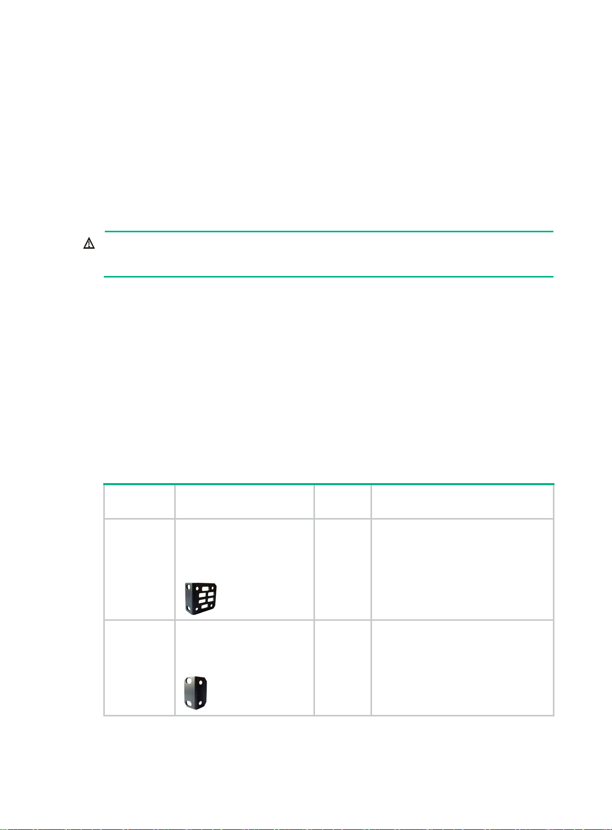
Table 4 Installation accessories
Product
code
5066-0850
5184-6978
Description Quantity Applicable models
1 U four-hole mounting bracket
kit (including one pair of
mounting brackets and eight
M4 countersunk screws)
(provided)
1 U two-hole mounting bracket
kit (including one pair of
mounting brackets and four M4
countersunk screws) (provided)
1 kit
1 kit
• HPE 1950 48G 2SFP+ 2XGT
• HPE 1950 24G 2SFP+ 2XGT
PoE+(370W)
• HPE 1950 48G 2SFP+ 2XGT
PoE+(370W)
• HPE 1950 12XGT 4SFP+
HPE 1950 24G 2SFP+ 2XGT
3
Page 8
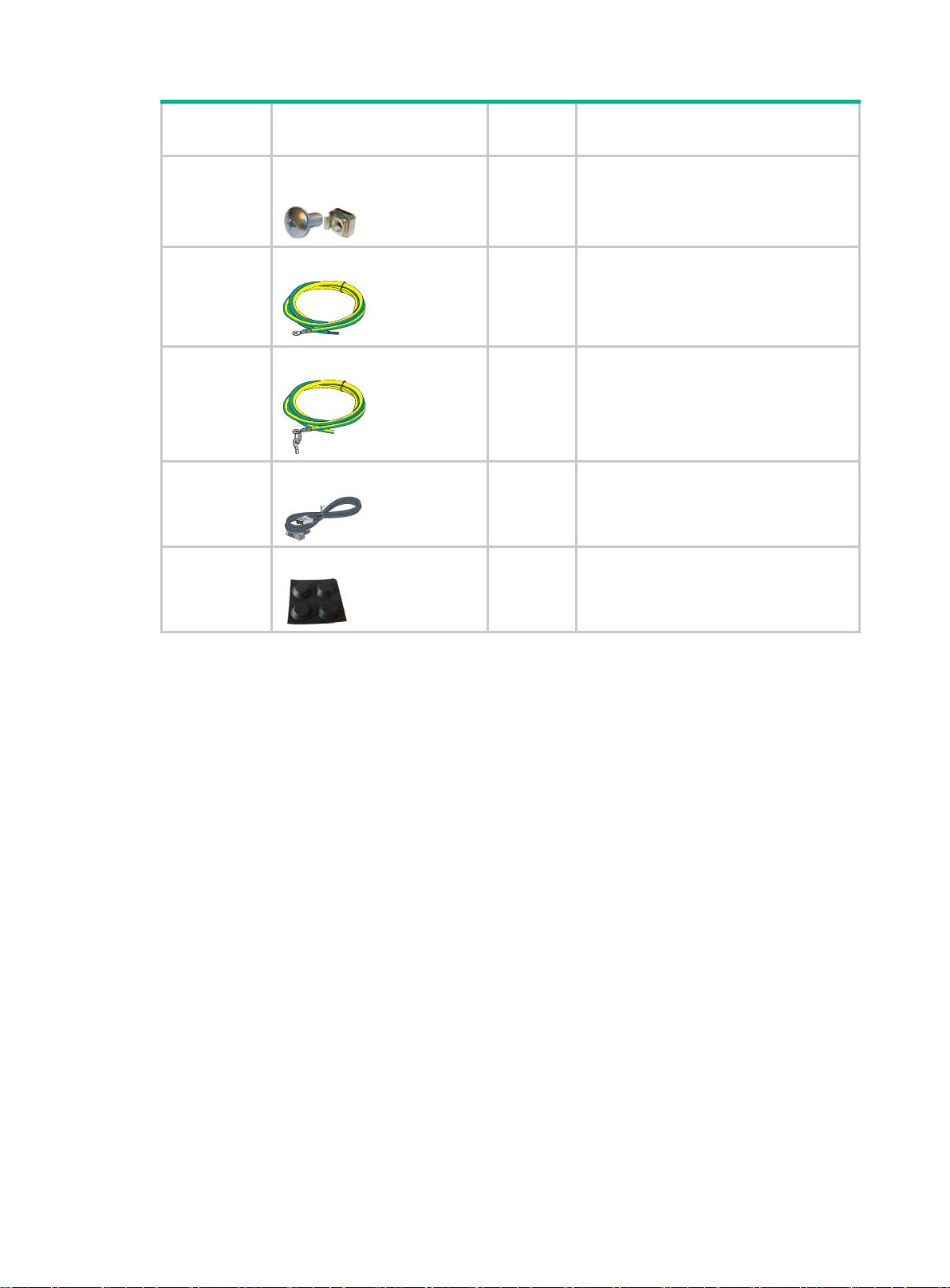
Product
code
N/A
5185-9292
5184-6729
5184-6719
Description Quantity Applicable models
M6 screw and floating nut (user
supplied)
Grounding cable (provided)
Grounding cable (provided)
Console cable (provided)
Rubber feet (provided)
N/A All HPE 1950 switches
• HPE 1950 24G 2SFP+ 2XGT
1
• HPE 1950 48G 2SFP+ 2XGT
• HPE 1950 12XGT 4SFP+
• HPE 1950 24G 2SFP+ 2XGT
1
PoE+(370W)
• HPE 1950 48G 2SFP+ 2XGT
PoE+(370W)
1 All HPE 1950 switches
5184-7298
1 All HPE 1950 switches
4
Page 9

Installing the switch
CAUTION:
Keep the tamperproof seal on a mounting screw on the chassis cover intact. If you want to open the
chassis, contact Hewlett Packard Enterprise for permission. Otherwise, Hewlett Packard Enterprise
shall not be liable for any consequences.
Figure 1 Hardware installation flow
Start
Install the switch
Ground the swtich
Connect power cords
Verify the installation
Turn on the circuit
breakers
Operating correctly?
Yes
Install transceiver modules
and cables
End
Troubleshoot the
No
Turn off the circuit
switch
breakers
5
Page 10

Installing the switch in a 19-inch rack
Mounting brackets
Table 5 Mounting brackets
Switch model Mounting brackets Views
HPE 1950 24G 2SFP+ 2XGT
• HPE 1950 48G 2SFP+ 2XGT
• HPE 1950 24G 2SFP+ 2XGT
PoE+(370W)
• HPE 1950 48G 2SFP+ 2XGT
PoE+(370W)
• HPE 1950 12XGT 4SFP+
One pair of 1U two-hole mounting
brackets
One pair of 1U four-hole mounting
brackets
Figure 2 1U two-hole mounting bracket
(1) Screw hole for attaching the bracket to the switch
(2 ) Screw hole for attaching the bracket to the rack post
Figure 3 1U four-hole mounting bracket
See Figure 2.
See Figure 3.
(1) Screw hole for attaching the bracket to the switch
(2 ) Screw hole for attaching the bracket to the rack post
Attaching the mounting brackets to the switch
The HPE 1950 12XGT 4SFP+, HPE 1950 24G 2SFP+ 2XGT, and HPE 1950 48G 2SFP+ 2XGT
switches provide one front mounting position (near the network ports) and one rear mounting
position (near the power supplies).
6
Page 11

The HPE 1950 24G 2SFP+ 2XGT PoE+(370W) and HPE 1950 48G 2SFP+ 2XGT PoE+(370W)
switches provide one front mounting position (near the network ports), one mid-mounting position,
and one rear mounting position (near the power supplies).
To attach the mounting brackets to the switch:
1. Determine the mounting position.
2. Align one mounting bracket with the screw holes at the mounting position. Use M4 screws
provided with the switch to attach the mounting bracket to the chassis.
3. Repeat step 2 to attach the other mo
unting bracket to the chassis.
Figure 4 Attaching a two-hole mounting bracket to the front mounting position on an HPE
1950 24G 2SFP+ 2XGT switch
Figure 5 Attaching a two-hole mounting bracket to the rear mounting position on an HPE
1950 24G 2SFP+ 2XGT switch
Figure 6 Attaching a four-hole mounting bracket to the front mounting position on an HPE
1950 24G 2SFP+ 2XGT PoE+(370W)
switch
7
Page 12

Figure 7 Attaching a four-hole mounting bracket to the rear mounting position on an HPE
1950 24G 2SFP+ 2XGT PoE+(370W)
switch
Figure 8 Attaching a four-hole mounting bracket to the mid-mounting position on an HPE
1950 24G 2SFP+ 2XGT PoE+(370W)
Rack-mounting the switch
This task requires two people. To mount the switch in the rack:
1. Wear an ESD wrist strap and make sure it makes good skin contact and is reliably grounded.
2. Verify that the mounting brackets have been securely attached to the switch chassis.
3. Install cage nuts in the mounting holes in the rack posts.
4. One person holds the switch chassis and aligns the mounting brackets with the mounting holes
in the rack posts, and the other person attaches the mounting brackets with screws to the rack.
5. Verify that the switch chassis is horizontal and secure.
switch
Figure 9 Mounting an HPE 1950 24G 2SFP+ 2XGT PoE+(370W) switch by the front mounting
position
8
Page 13

Figure 10 Mounting an HPE 1950 24G 2SFP+ 2XGT PoE+(370W) switch by the rear mounting
position
Figure 11 Mounting an HPE 1950 24G 2SFP+ 2XGT PoE+(370W) switch by the mid-mounting
position
Mounting the switch on a workbench
IMPORTANT:
• Ensure 10 cm (3.9 in) of clearance around the chassis for heat dissipation.
• Do not place heavy objects on the switch.
If a standard 19-inch rack is not available, you can place the switch on a workbench.
To mount the switch on a workbench:
1. Verify that the workbench is sturdy and reliably grounded.
2. Place the switch bottom up, and clean the round holes in the chassis bottom with a dry cloth.
3. Attach the rubber feet to the four round holes in the chassis bottom.
4. Place the switch upside up on the workbench.
9
Page 14

Figure 12 Mounting the switch on a workbench
Grounding the switch
WARNING!
Correctly connecting the switch grounding cable is crucial to lightning protection and EMI protection.
The power input end of the switch has a noise filter, whose central ground is directly connected to the
chassis to form the chassis ground (commonly known as PGND). You must securely connect this
chassis ground to the earth to minimize the potential for system damage, maximize safety at the site,
and minimize EMI susceptibility of the system.
You can ground the switch in one of the following ways, depending on the grounding conditions
available at the installation site:
• Grounding the switch with a grounding strip
• Grounding the switch with a grounding conductor buried in the earth ground
NOTE:
The power and grounding terminals in this section are for illustration only.
Grounding the switch with a grounding strip
WARNING!
Connect the grounding cable to the grounding system in the equipment room. Do not connect it to a
fire main or lightning rod.
If a grounding strip is available at the installation site, use the grounding strip to ground the switch.
To ground the switch by using a grounding strip:
1. Connect one end of the grounding cable to the grounding screw on the switch.
a. Remove the grounding screw from the rear panel of the switch chassis.
b. Attach the grounding screw to the ring terminal of the grounding cable.
c. Use a screwdriver to fasten the grounding screw into the grounding screw hole.
10
Page 15

Figure 13 Connecting the grounding cable to the grounding hole of the switch
(1) Chassis rear panel (2) Grounding sign
(3) Grounding hole (4) Ring terminal
(5) Grounding cable (6) Grounding screw
2. Connect the other end of the grounding cable to the grounding strip.
a. Cut the grounding cable to a length according to the distance between the switch and the
grounding strip.
b. Peel 20 mm (0.79 in) of insulation sheath by using a wire stripper.
c. Use the needle-nose pliers to bend the bare wire.
d. Hook the grounding cable to the post on the grounding strip, and use the hex nut to secure
the cable to the post.
Figure 14 Connecting the grounding cable to a grounding strip
(1) Grounding post (2) Grounding strip
(3) Grounding cable (4) Hex nut
Grounding the switch with a grounding conductor buried in the earth ground
If the installation site has no grounding strips, but earth ground is available, hammer a 0.5 m (1.64 ft)
or longer angle iron or steel tube into the earth ground to serve as a grounding conductor.
11
Page 16

The dimensions of the angle iron must be at least 50 × 50 × 5 mm (1.97 × 1.97 × 0.20 in). The steel
tube must be zinc-coated and its wall thickness must be at least 3.5 mm (0.14 in).
Weld the yellow-green grounding cable to the angel iron or steel tube and use cathodic protection to
protect the joint from corrosion.
Figure 15 Grounding the switch by burying the grounding conductor into the earth ground
(1) Grounding screw (2) Grounding cable (3) Earth
(4) Joint (5) Grounding conductor (6) Chassis rear panel
Connecting the power cord
CAUTION:
• Provide a circuit breaker for each power cord.
• Before connecting the power cord, make sure the circuit breaker on the power cord is turned off.
Table 6 Power cord connection procedures at a glance
Switch model
• HPE 1950 24G 2SFP+ 2XGT
• HPE 1950 48G 2SFP+ 2XGT
• HPE 1950 24G 2SFP+ 2XGT
PoE+(370W)
• HPE 1950 48G 2SFP+ 2XGT
PoE+(370W)
HPE 1950 12XGT 4SFP+
As a best practice, use HPE RPS and cables for RPS power input.
Available power
source
AC power source Connecting the switch to an AC power source
AC power source Connecting the switch to an AC po
HPE A-RPS1600 Connecting the switch to an A-RPS1600
AC power source Connecting the switch to an AC po
HPE A-RPS800 Connecting the switch to an A-RPS800
Connection procedure reference
wer source
wer source
Connecting the switch to an AC power source
1. Connect the AC power cord plug to the AC-input power receptacle on the switch.
2. Pass the cable tie through the cable retainer.
3. Use the cable tie to secure the AC power cord to the cable retainer.
4. Connect the other end of the power cord to an AC power source.
12
Page 17

Figure 16 Passing the cable tie through the cable retainer
Figure 17 Using the cable tie to secure the AC power cord
Connecting the switch to an A-RPS1600
1. Orient the plug with the power receptacle on the power supply, and insert the plug into the
receptacle (See callout 1 in Figure 18).
If you cannot insert the plug into the receptacle, re-orient the plug rather than use excessive
force to push it in.
2. Tighten the screws on the plug with a flat-blade screwdriver to secure the plug in the RPS
receptacle. See callout 2 in Figure 18.
3. Con
nect the other end of the power cord to an A-RPS1600.
13
Page 18

Figure 18 Connecting the A-RPS1600 power cord to an HPE 1950 24G 2SFP+ 2XGT
PoE+(370W) switch
1
2
Connecting the switch to an A-RPS800
1. Remove the cover over the DC-input receptacle on the switch as shown in Figure 19.
Reinstall the cover if you are not to connect a power cord to the receptacle.
2. Align the plug of the power cord with the DC-input receptacle on the power supply, and insert
the plug into the power receptacle. See callout 1 in Figure 20.
If you cannot inse
force to push it in.
3. Tighten the screws on the plug with a flat-blade screwdriver to secure the plug in place. See
callout 2 in Figure 20.
4. Con
nect the other end of the power cord to the A-RPS800.
Figure 19 Removing the cover over the DC-input power receptacle
rt the plug into the receptacle, re-orient the plug rather than use excessive
14
Page 19

Figure 20 Connecting the A-RPS800 power cord to an HPE 1950 12XGT 4SFP+ switch
Verifying the installation
After you complete the installation, verify the following items:
• There is enough space for heat dissipation around the switch.
• The rack or workbench is stable.
• The grounding cable is securely connected.
• The correct power source is used.
• The power cords are correctly connected.
• All the interface cables are cabled indoors. If any cable is routed outdoors, verify that the socket
strip with lightning protection and lightning arresters for network ports have been correctly
connected.
15
Page 20

Accessing the switch for the first time
You can use one of the following default methods to access the switch:
• Logging in to the Web interface—
• Logging in to the quick set-up CLI—
Logging in to the Web interface
Log in to the Web interface through HTTP or HTTPS.
Setting up the configuration environment
Before you log in to the Web interface, use a twisted pair cable to connect the switch to the network,
or to the NIC of a PC.
Restrictions and guidelines
To ensure a successful login, verify that your operating system and Web browser meet the
requirements, and follow the guidelines in this section.
For detailed device configuration.
For quick set-up of key device configuration.
Web browser requirements
The following Web browsers are supported:
• Internet Explorer 8 or higher.
• Google Chrome 10 or higher.
• Mozilla Firefox 4 or higher.
• Opera 11.11 or higher.
• Safari 5.1 or higher.
To access the Web interface, you must use the following browser settings:
• Accept the first-party cookies (cookies from the site you are accessing).
• To ensure correct display of webpage contents after software upgrade or downgrade, clear data
cached by the browser before you log in.
• Enable active scripting or JavaScript, depending on your Web browser.
• If you are using a Microsoft Internet Explorer browser, you must enable the following security
settings:
{ Run ActiveX controls and plug-ins.
{ Script ActiveX controls marked safe for scripting.
Default login settings
Use the settings in Table 7 for the first login.
Table 7 Default login settings
Item Setting
Device IP (VLAN-interface 1)
IP address mask
Username
See "Logging in to the Web interface for the first time."
admin
16
Page 21

Item Setting
Password None
User role network-admin
NOTE:
If the network has a DHCP server, you must use the DHCP assigned IP address to access the
device. For more information, see "Logging in to the Web interface for the first time."
Concurrent login users
The Web interface allows a maximum of 32 concurrent users. If this limit is reached, login attempts
will fail.
Logging in to the Web interface for the first time
IMPORTANT:
For security purposes, change the login information and assign access permissions immediately
after the first successful login.
By default, HTTP and HTTPS are enabled.
To log in to the Web interface:
1. Use an Ethernet cable to connect the configuration terminal to an Ethernet port on the device.
2. Identify the IP address and mask of the device.
{ If the device is not connected to the network, or no DHCP server exists on the network, the
device uses the default IP address and mask. The default mask is 255.255.0.0. The default
IP address is 169.254.xxx.xxx, where xxx.xxx depends on the rightmost two bytes of the
MAC address. Find the MAC address label on the device and use the following rules to
determine the rightmost two bytes for the IP address:
Rightmost two bytes of the MAC
address
All 0s 0.1
All Fs 255.1
Not all 0s or all Fs
Rightmost two bytes for the IP address
Decimal values of the rightmost two bytes of the MAC
address
For example:
MAC address IP address
08004E080000 169.254.0.1
08004E08FFFF 169.254.255.1
08004E082A3F
{ If a DHCP server is available, the device obtains an IP address from the server. To identify
169.254.42.63 (The decimal value of 2A is 42. The
value of 3F is 63.)
the address, log in to the device through the console port, and then execute the summary
command. The following is the sample output:
<Sysname> summary
17
Page 22

Select menu option: Summary
IP Method: DHCP
IP address: 10.153.96.86
Subnet mask: 255.255.255.0
Default gateway: 0.0.0.0
For more information about console login, see the getting started guide for the device.
3. Assign the login host an IP address in the same subnet as the device.
4. Open the browser and enter login information.
a. In the address bar, enter the IP address of the device.
− HTTP access—Enter the address in the http://ip-address:port or ip-address:port
format.
− HTTPS access—Enter the address in the https://ip-address:port format.
The ip-address argument represents the IP address of the device. The port argument
represents the HTTP or HTTPS service port. The default port number is 80 for HTTP and
443 for HTTPS. You do not need to enter the port number if you have not changed the
service port setting.
b. On the login page, enter the default username (admin) and the verification code.
You do not need to enter a password at the first login.
c. Click Login.
5. Change the login information.
{ To change the password of the login user (admin at the first login), click the Admin icon
.
{ To add new user accounts and assign access permissions to different users, select Device >
Maintenance > Administrators.
For more information about how to configure the device by using the Web interface, see the user
guide for the switch.
Logging in to the quick set-up CLI
Setting up the configuration environment
The HPE 1950 12XGT 4SFP+ switch has a serial console port and a mini USB console port. You can
access the switch through the serial console port or the mini USB console port. As a best practice,
use the serial console port to access the HPE 1950 12XGT 4SFP+ switch. To access the switch
through the mini USB console port, you need to prepare a mini USB console cable. Only the mini
USB console port is available if you connect both the serial console port and mini USB console port.
The other HPE 1950 switches have only a serial console port.
18
Page 23

Figure 21 Connecting the serial console port to a PC
Connecting the console cable
A console cable is an 8-core shielded cable. It has a crimped RJ-45 connector at one end for
connecting to the console port of the switch, and a DB-9 female connector at the other end for
connecting to the serial port on the configuration terminal.
Figure 22 Console cable
A side
Pin 9
A
Pin 1
Main label
8
1
B side
B
Table 8 Console cable pinouts
RJ-45 Signal DB-9 Signal
1 RTS 8 CTS
2 DTR 6 DSR
3 TXD 2 RXD
4 SG 5 SG
5 SG 5 SG
6 RXD 3 TXD
7 DSR 4 DTR
8 CTS 7 RTS
To connect a terminal (for example, a PC) to the switch:
1. Connect the DB-9 female connector of the console cable to the serial port of the PC.
2. Identify the mark on the console port. Make sure you are connecting to the correct port.
19
Page 24

3. Connect the RJ-45 connector to the console port of the switch.
NOTE:
The serial ports on PCs do not support hot swapping. To connect a PC to an operating switch, first
connect the PC end. To disconnect a PC from an operating switch, first disconnect the switch end.
Connecting the mini USB console cable
A mini USB console cable has a mini USB-Type B connector at one end to connect to the mini USB
console port on the switch, and a standard USB Type A connector at the other end to connect to the
USB port on the PC.
To connect to the PC through the mini USB console cable:
1. Connect the standard USB Type A connector to the USB port on the PC.
2. Connect the mini USB Type B connector to the mini USB console port on the switch.
3. Click the following link, or copy it to the address bar on the browser to log in to download page
of the USB console driver, and download the driver.
http://www.exar.com/connectivity/uart-and-b
4. Select a driver program according to the operating system you use:
{ XR21V1410_XR21B1411_Windows_Ver1840_x86_Installer.EXE—32-bit operating
system.
{ XR21V1410_XR21B1411_Windows_Ver1840_x64_Installer.EXE—64-bit operating
system.
5. Click Next on the installation wizard.
ridging-solutions/usb-uarts/xr21v1410
Figure 23 Device Driver Installation Wizard
6. Click Continue Anyway if the following dialog box appears.
20
 Loading...