

Page 1

5257/5257ACL
Installation and User's
Guide for NonStop
Himalaya S-Series Tape
Enclosures
Abstract
This guide is written for installers, users, and maintainers of the 5257/5257ACL in a
NonStop™ Himalaya S-Series tape enclosure.
Product Version
N.A.
Supported Releases
This publication supports G06.14 and all subsequent G-series releases until otherwise
indicated by its replacement publication.
Part Number Published
522344-001 November 2001
Page 2

Document History
Part Number Product Version Published
522344-001 N.A. November 2001
Ordering Information
For manual ordering information: domestic U.S. customers, call 1-800-243-6886; international customers, contact
your localsales representative.
Document Disclaimer
Information contained in a manual is subject to change without notice. Please check with your authorized
representative to make sure you have the most recent information.
Export Statement
Export of the information containedin this manual may require authorization from the U.S. Department of
Commerce.
Examples
Examples and sample programs are for illustration only and may not be suited for your particular purpose. The
inclusion of examples and sample programs in the documentation does not warrant, guarantee , or make any
representationsregarding the use or the results of the use of any examples or sample programs in any
documentation. You should verify the applicability of any example or sample program before placing the software
into productive use.
U.S. Government Customers
FOR U.S. GOVERNMENT CUSTOMERS REGARDING THIS DOCUMENTATION AND THE ASSOCIATED
SOFTWARE :
These notices shall be marked on any reproduction of this data, in whole or in part.
NOTICE: Notwithstanding any other lease or license that may pertain to, or accompany the delivery of, this
computer software, the rightsof the Government regarding its use, reproduction and disclosureare as set forth in
Section 52.227-19 of the FARS Computer Software—Restricted Rights clause.
RESTRICTED RIGHTS NOT ICE: Use, duplication, or disclosure by the Government is subject to the
restrictionsas set forth in subparagraph (c)(1)(ii) of the Rights in Technical Data and Computer Software clause at
DFARS 52.227-7013.
RESTRICTED RIGHTS LEGEND: Use, duplication or disclosure by the Government is subject to restrictions
as set forth in paragraph (b)(3)(B) of the rights in Technical Data and Computer Software clause in
DAR 7-104.9(a). This computer software is submitted with “restricted rights.” Use, duplication or disclosure is
subject to the restrictions as set forth in NASA FAR SUP 18-52 227-79 (April 1985) “Commercial Computer
Software—Restricted Rights (April 1985).” If the contract contains the Clause at 18-52 227-74 “Rights in Data
General”then the “Alternate III” clause applies.
U.S. Government Users Restricted Rights — Use, duplicationor disclosure restricted by GSA ADP Schedule
Contract.
Unpublished — All rights reserved under the Copyright Laws of the United States.
Page 3

5257/5257ACL Installation and
User's Guide for NonStop Himalaya
S-Series Tape Enclosures
Index Figures Tables
What’s New in This Manual vii
Manual Information
New and Changed Information
About This Guide
Who Should Read This Guide
Your Comments Invited
Notation Conventions
ix
vii
vii
ix
ix
ix
1. Overview and Features
Guide Overview 1-1
Product Overview
NonstopTM Himalaya Tape Enclosure
5257/5257ACL Tape Drives
High Capacity Features
Backward Read Compatibility (BRC) Transfer Rates
1-1
1-1
1-2
1-2
1-2
2. Unpacking and Installing the Tape Enclosures
Unpacking the Tape Enclosure 2-2
Suggested Tape Enclosure Configuration Options
Tape Enclosure Configuration Hazards
Tape Enclosure Dimensions and Configurations
Base Tape Enclosure
Stackable Tape Enclosure
Tape Enclosure Rear Cover
Installing the 5257/5257ACL Tape Drives
2-12
2-12
2-13
3. Installing the 5257 Tape Drive
Connecting the Power Cord 3-1
Compaq Computer Corporation—522344-001
2-10
2-11
2-11
2-14
i
Page 4

Contents
Connecting the SCSI Cables 3-2
4. Ope rating the 5257 Tape Drive
Connecting the SCSI Cable to the Tape Drive
Connecting the SCSI Cables to the Server
Powering on the Tape Drive
Power-On Self-Test
3-3
5257 Troubleshooting Chart
3-3
3-4
3-2
3-3
4. Operating the 5257 Tape Drive
The Front Panel 4-1
Super DLTtape 1 Tape Cartridge
Cartridge Write-Protect Switch
Loading a Cartridge
Unloading a Cartridge
Preserving Cartridges
4-4
4-4
4-5
4-2
4-2
5. Installing and Co nfig u ring the 5257ACL Tape Drive
Connecting the Power Cord 5-1
Installing the SCSI Cables
5-1
Connecting the SCSI Cable to the Tape Drive
Connecting the SCSI Cable to the Server
Powering on the Tape Drive
5-3
Configuring the 5257ACL Tape Drive
Setting the SCSI ID
Setting Up Reserved Slots
5-3
5-5
Descriptions of Configuration Options
Set Data Format
Set SCSI
5-6
Set Library Mode
Set Element Base
Set Identification
Set Date
Set Time
5-7
5-7
5-6
5-6
5-6
5-7
5-2
5-2
5-3
5-6
Set Baud Rate
Set Serial number
5257/5257ACL Installation and User's Guide for NonStop Himalaya S-Series Tape Enclosures—522344-001
5-7
5-7
ii
Page 5

Contents
6. Operating the 5257ACL Tape Enclosure
Set Unload Mode 5-7
Set Autoclean Mode
Set Negotiation
Set Reserved Slots
Set Special Configurations
Set Default
5-8
5-7
5-7
5-8
5-8
6. Operating the 5257ACL Tape Enclosure
Front Panel 6-1
Power Switch
Magazine Door
Control Panel
Media Locks
The Main Menu
Entering the Main Menu Mode
Exiting the Main Menu
Navigating the Main Menu
6-1
6-1
6-2
6-5
6-7
6-8
6-9
6-9
Load/Unload
Drive Status (DLT1) Submenu
Map Information Screen
Unlocking the Control Panel
Displaying Firmware Revision
Displaying Error Logs
Inserting and Removing Cartridges
Removing the Magazine
Emergency Magazine Removal
6-9
6-11
6-13
6-15
6-16
6-16
6-17
6-17
6-18
Inserting a Magazine Into the 5257ACL
Inserting Cartridges Into the Magazine
Tape Requirements
Cartridge Handling and Storage
Write Protection
6-19
6-19
6-20
6-18
6-18
5257/5257ACL Installation and User's Guide for NonStop Himalaya S-Series Tape Enclosures—522344-001
iii
Page 6

Contents
7. Configuri ng the 5257/52 57ACL Tape Dri ve for the
NonStop Hima laya S-Series Serve r
7. Configuring the 5257/5257ACL Tape Drive for the NonStop
Himalaya S-Series Server
Supported Connections 7-1
Configuring the Modular T ape Enclosure for the NonStop Himalaya S-Series Servers
(SNDA) 7-2
Configuring the Modular T ape Subsystem Online Using SCF (SNDA)
Example 2: Changing the Values of Tape Drive Attributes (SNDA)
Example 3: Deleting a Tape Drive From the System (SNDA)
Configuring the Modular T ape Enclosure for the NonStop Himalaya S-Series Servers
(PMF/IOMF) 7-3
Completing the PMF CRU Configuration Form (PMF/IOMF)
Configuring the Modular T ape Enclosure Online Using SCF (PMF/IOMF)
Example 1: Defining and Adding a Tape Drive (PMF/IOMF)
Example 2: Changing the Values of Tape Drive Attributes (PMF/IOMF)
Example 3: Deleting a Tape Drive From the System (PMF/IOMF)
7-3
7-4
7-5
8. Maintenance for the 5257ACL
Cleaning Cartridge 8-1
Required Location for the Cleaning Cartridge
Installing
When to Run
8-1
8-2
8-1
7-2
7-2
7-5
7-6
7-7
Running From the Front Panel
Removing the Cleaning Cartridge
8-2
8-3
Index
Examples
Figures
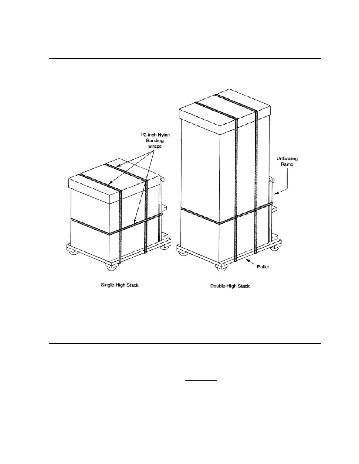
Figure 2-1. How the Tape Enclosures are Packaged 2-2
Figure 2-2.
Figure 2-3.
Figure 2-4.
Figure 2-5.
Figure 2-6.
Figure 2-7.
5257/5257ACL Installation and User's Guide for NonStop Himalaya S-Series Tape Enclosures—522344-001
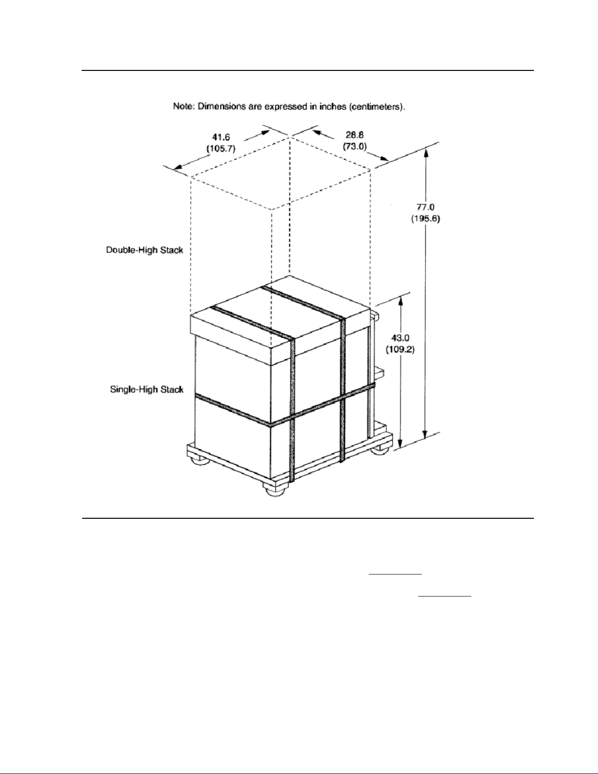
Package Dimensions for the Tape Enclosures 2-3
Remove the Cartons and the Anti-static Bag 2-5
The Ramp Being Placed on the Pallet 2-7
The Operation of the Leveling Pads 2-7
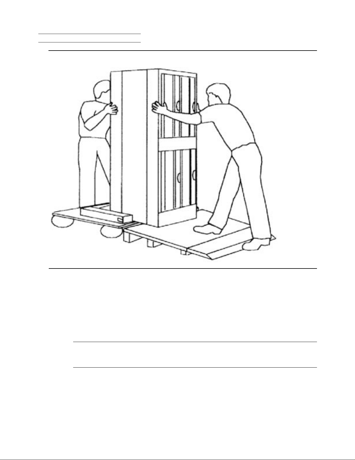
Unloading the Platform 2-9
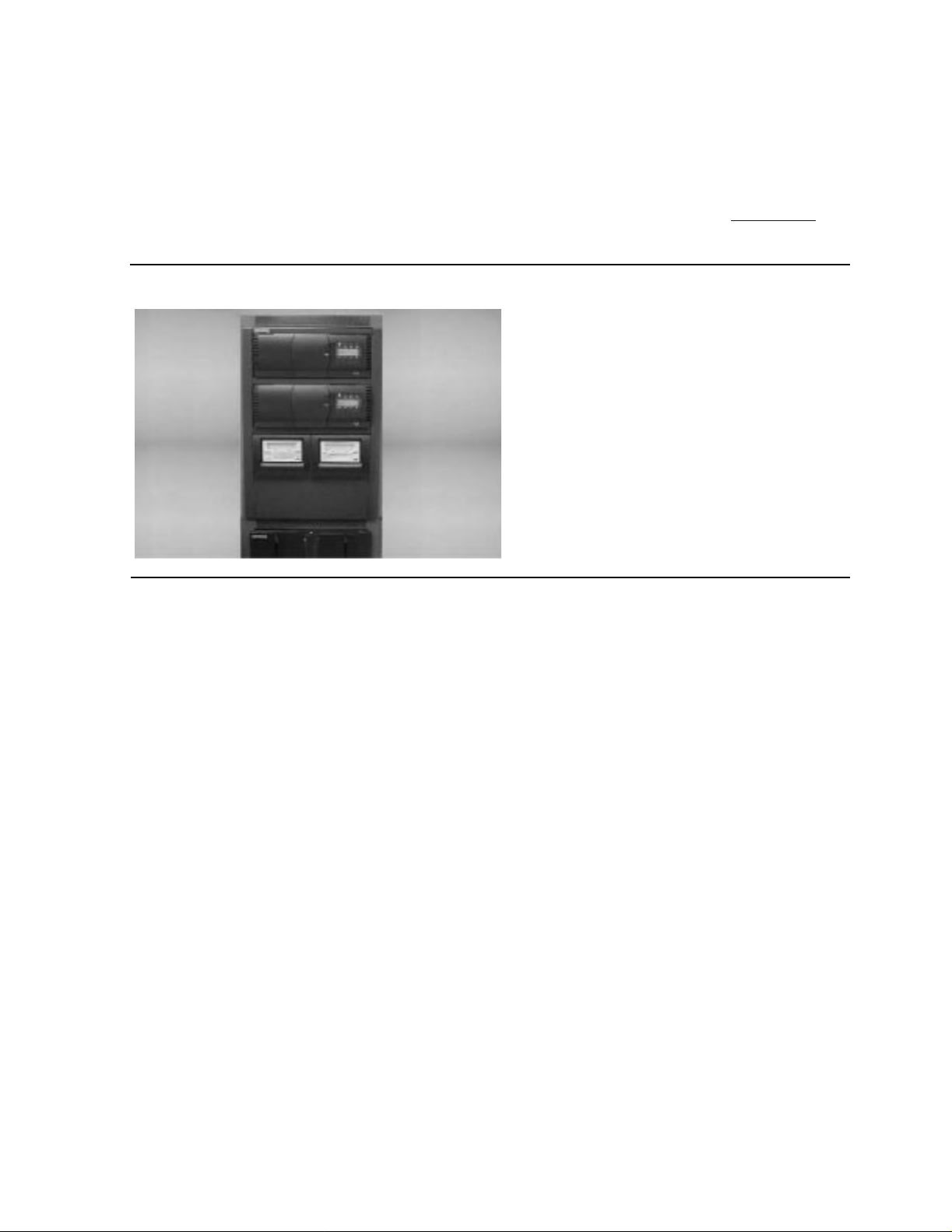
T ape Enclosure on Server 2-10
iv
Page 7

Contents
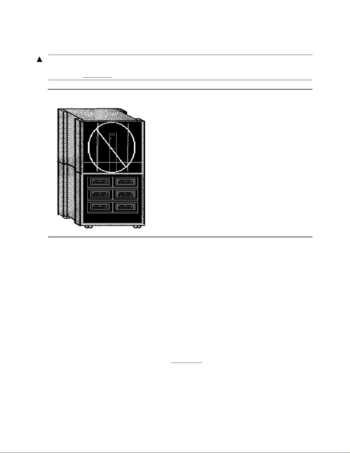
Figure 2-8. Server on Tape Enclosure 2-11
Figures
Figure 2-9.
Figure 2-10.
Figure 2-11.
Figure 3-1.
Figure 3-2.
Figure 4-1.
Figure 4-2.
Figure 4-3.
Figure 4-4.
Figure 4-5.
Figure 5-1.
Figure 5-2.
Figure 5-3.
Figure 5-4.
Figure 5-5.
Dimensions of the Base and Stackable Tape Enclosure 2-12
Tape Enclosure with a Rear Cover Attached 2-13
Push-Button Rivets 2-14
Attaching the Power Cord 3-1
Rear View of the 5257 Tape Drive 3-2
Tape Drive Front Panel 4-1
Super DLTtapeTM 1 Tape Cartridge 4-2
Tape Cartridge 4-3
Loading a Tape Cartridge 4-4
Unloading a Tape Cartridge 4-5
Rear View of the 5257ACL Tape Drive 5-2
Default Screen 5-3
Main Menu 5-4
Configure Submenu 5-4
Set SCSI Submenu 5-4
Figure 5-6.
Figure 5-7.
Figure 6-1.
Figure 6-2.
Figure 6-3.
Figure 6-4.
Figure 6-5.
Figure 6-6.
Figure 6-7.
Figure 6-8.
Figure 6-9.
Figure 6-10.
Figure 6-11.
Figure 6-12.
Figure 6-13.
SCSI Submenu Scrolled 5-5
Set Reserved Slots Submenu 5-5
POST Screen 6-3
Initialization Screen 6-4
Default Screen 6-4
Fault Screen 6-5
5257ACL Menu Structure 6-7
Main Menu 6-8
Panel Locked Screen 6-8
Code Entry Submenu 6-8
Show Status Menu 6-10
Show Status Submenu 6-10
Drive Status Submenu 6-11
Map Info Submenu 6-13
Security Menu 6-14
Figure 6-14.
Figure 6-15.
5257/5257ACL Installation and User's Guide for NonStop Himalaya S-Series Tape Enclosures—522344-001
Code Select Submenu 6-15
Code Accept Submenu 6-15
v
Page 8

Contents
Figure 6-16. Panel Locked Screen 6-15
Tables
Figure 6-17.
Figure 6-18.
Figure 6-19.
Figure 6-20.
Figure 6-21.
Figure 6-22.
Figure 6-23.
Figure 6-24.
Figure 6-25.
Figure 6-26.
Figure 6-27.
Figure 6-28.
Figure 7-1.
Figure 8-1.
Figure 8-2.
Code Entry Submenu 6-16
Error History Screen 6-16
Magazine in Place 6-17
Tape Magazine with Cartridges Installed 6-19
Default Screen ‘ 6-20
Main Menu 6-20
Load/Unload Initial Screen 6-21
Load/Unload From Entry Screen 6-21
Load/Unload To Entry Screen 6-22
Confirmation Screen 6-22
Load/Unload ‘In Progress’ Screen 6-22
Updated Default Screen 6-23
Both PMF CRU’s Installed 7-4
Main Menu 8-2
Maintenance Submenu 8-2
Figure 8-3.
Figure 8-4.
Figure 8-5.
Maintenance Submenu 8-2
Cleaning Confirmation Screen 8-3
Cleaning In Progress 8-3
Tables
Table 3-1. SCSI Cables 3-2
Table 3-2.
Table 3-3.
Table 4-1.
Table 4-2.
Table 5-1.
Table 5-2.
Table 6-1.
Table 7-1.
Connections Supported for 5257/5257ACL Tape Drives 3-3
Troubleshooting Chart 3-4
Before Loading the Cartridge 4-3
After Loading the Cartridge and Operating 4-3
Connections Supported for 5257/5257ACL Tape Drives 5-3
5257ACL Configuration Options (page 1 of 2) 5-8
Control Panel Functions 6-3
Connections Supported for 5257/5257ACL Tape Drives 7-1
5257/5257ACL Installation and User's Guide for NonStop Himalaya S-Series Tape Enclosures—522344-001
vi
Page 9

What’s New in This Manual
Manual Information
5257/5257ACL Installation and User'sGuide for NonStop HimalayaS-Series TapeEnclosures
Abstract
This guide is written for installers, users, and maintainers of the 5257/5257ACL in a
NonStop™ Himalaya S-Series tape enclosure.
Product Version
N.A.
Supported Releases
This publication supports G06.14 and all subsequent G-series releases until oth erwise
indicated by its replacement publication.
Part Number Published
522344-001 November 2001
Document History
Part Number Product Version Published
522344-001 N.A. November 2001
New and Changed Information
This is a new manual.
5257/5257ACL Installation and User's Guide for NonStop Himalaya S-Series Tape Enclosures—522344-001
vii
Page 10

What’s New in This Manual
New and Changed Information
5257/5257ACL Installation and User's Guide for NonStop Himalaya S-Series Tape Enclosures—522344-001
viii
Page 11

About This Guide
This guide is written for installers, users, and maintainers of the 5257/5257ACL in a
NonStop™ Himalaya S-Series tape enclosure.
Who Should Read This Guide
This guide is written for installers, users, and maintainers of the 5258ACL tape d rive.
Your Comments Invited
After using this manual, please take a mome nt to send us your comments. You can do
this by returning a Reader Comment Card or by sending an Internet m ail message.
A Reader Comment Card is located at the back of printed manuals and as a separate file
on the User Documentation disc. You can either fax or mail the card to us. The fax
number and mailing address are provided on the card.
Also provided on the Reader Comment Card is an Internet mail address. When you
send an Internet mail message to us, we immediately acknowledge receipt of your
message. A detailed response to your message is sent as soon as possible. Be sure to
include your name, company name, address, and phone nu mber in your message. If
your comments are specific to a particular manual, also include the part number and title
of the manual.
Many of the improvements you see in manuals are a result of suggestions from our
customers. Please take this opportunity to help us improve future manuals.
Notation Conventions
Hypertext L inks
Blue underline is used to indicate a hypertext link within text. By clicking a passage of
text with a blue underline, you are taken to the location described. For example:
This requirement is described under Backup DAM Volumes and Physical Disk
Drives on page 3-2.
General Syntax Notation
The following list summarizes the notation conventions for syntax presentation in this
manual.
UPPERCASE LETTERS. Uppercase letters indicate keywords and reserved words; enter
these items exactly as shown. Items not enclosed in brackets are required. For example:
MAXATTACH
5257/5257ACL Installation and User's Guide for NonStop Himalaya S-Series Tape Enclosures—522344-001
ix
Page 12

About This Guide
General Syntax Notation
lowercase italic letters. Lowercase italic letters indicate variable items that you supply.
Items not enclosed in brackets are required. For example:
file-name
[ ] Brackets. Brackets enclose optional syntax items. For example:
TERM [\
INT[ERRUPTS]
system-name
.]$
terminal-name
A group of items enclosed in brackets is a list from which you can choose one item or
none. The items in the list may be arranged either vertically, with aligned brackets on
each side of the list, or horizontally, enclosed in a pair of brackets and separated by
vertical lines. For example:
FC [
[
[
K [ X | D ]
num
-num
text
]
]
]
address
-1
{ } Braces. A group of items enclosed in braces is a list from which you are required to
choose one item. The items in the list may be arranged either vertically, with aligned
braces on each side of the list, or horizontally, enclosed in a pair of braces and separated
by vertical lines. For example:
LISTOPENS PROCESS { $
{ $
ALLOWSU { ON | OFF }
appl-mgr-name
process-name
}
}
| Vertical Line. A vertical line separates alternatives in a horizontal list that is enclosed in
brackets or braces. For example:
INSPECT { OFF | ON | SAVEABEND }
… Ellipsis. An ellipsis immediately following a pair of brackets or braces indicates that you
can repeat the enclosed sequence of syntax items any number of times. For example:
M
address
[ - ] {0|1|2|3|4|5|6|7|8|9}...
-1 [ ,
new-value
]...
An ellipsis immediately following a single syntax item indicates that you can repeat that
syntax item any number of times. For example:
"
s-char
..."
Punctuation. Parentheses, commas, semicolons, and other symbols not previously described
must be entered as shown. For example:
error
LISTOPENS SU $
5257/5257ACL Installation and User's Guide for NonStop Himalaya S-Series Tape Enclosures—522344-001
:= NEXTFILENAME (
process-name.#su-name
file-name
x
) ;
Page 13

About This Guide
General Syntax Notation
Quotation marks around a symbol such as a bracket or brace indicate the symbol is a
required character that you must enter as shown. For example:
"["
repetition-constant-list
"]"
Item Spacing. Spaces shown between items are required unless one of the items is a
punctuation symbol such as a parenthesis or a comma. For example:
CALL STEPMOM (
process-id
) ;
If there is no space between two items, spaces are not permitted. In the following
example, there are no spaces permitted between the period and any other items:
$
process-name.#su-name
Line Spacing. If the syntax of a command is too long to fit on a single line, each continuation
line is indented three spaces and is separated from the preceding line by a blank line.
This spacing distinguishes items in a continuation line from items in a vertical list of
selections. For example:
ALTER [ / OUT
[ ,
attribute-spec
file-spec
]...
/ ] LINE
The following list summarizes the notation conventions for the presentation of displayed
messages in this manual.
Bold Text. Bold text in an example indicates user input entered at the terminal. For example:
ENTER RUN CODE
?123
CODE RECEIVED: 123.00
The user must press the Return key after typing the input.
Nonitalic text. Nonitalic letters, numbers, and punctuation indicate text that is displayed or
returned exactly as shown. For example:
Backup Up.
lowercase italic letters. Lowercase italic letters indicate variable items whose values are
displayed or returned. For example:
p-register
process-name
[ ] Brackets. Brackets enclose items that are sometimes, but not always, displayed. For
example:
Event number =
number
[ Subject =
first-subject-value
]
A group of items enclosed in brackets is a list of all possible items that can be displayed,
of which one or none might actually be displayed. The items in the list might be
5257/5257ACL Installation and User's Guide for NonStop Himalaya S-Series Tape Enclosures—522344-001
xi
Page 14

About This Guide
General Syntax Notation
arranged either vertically, with aligned brackets on each side of the list, or horizontally,
enclosed in a pair of brackets and separated by vertical lines. For example:
proc-name
trapped [ in SQL | in SQL file system ]
{ } Braces. A group of items enclosed in braces is a list of all possible items that can be
displayed, of which one is actually displayed. The items in the list might be arranged
either vertically, with aligned braces on each side of the list, or horizontally, enclosed in
a pair of braces and separated by vertical lines. For example:
obj-type obj-name
{ Object | Operator | Service }
process-name
{ Operator Request. }
{ Unknown. }
State changed from
state changed to
old-objstate
state
, caused by
to
objstate
| Vertical Line. A vertical line separates alternatives in a horizontal list that is enclosed in
brackets or braces. For example:
Transfer status: { OK | Failed }
% Percent Sign. A percent sign precedes a number that is not in decimal notation. The
% notation precedes an octal number. The %B notation precedes a binary number. The
%H notation precedes a hexadecimal number. For example:
%005400
P=%
p-register
E=%e-
register
Change bars are used to indicate substantive differences between this edition of the
manual and the preceding edition. Change bars are vertical rules placed in the right
margin of changed portions of text, figures, tables, examples, and so on. Change bars
highlight new or revised information. For example:
The message types specified in the REPORT clause are different in the COBOL85
environment and the Common Run-Time Environment (CRE).
The CRE has many new message types and some new message type codes for old
message types. In the CRE, the message type SYSTEM includes all messages
except LOGICAL-CLOSE and LOGICAL-OPEN.
5257/5257ACL Installation and User's Guide for NonStop Himalaya S-Series Tape Enclosures—522344-001
xii
Page 15

1
Overview and Features
This section includes these topics:
Topic Page
Guide Overview
Product Overview
High Capacity Features
Backward Read Compatibility (BRC) Transfer Rates
Guide Overview
This guide should be used in conjunction with the latest versions of these Compaq
manuals:
Source Manual
COMPAQ SCF Reference Manual for the Storage Subsystem
COMPAQ SCF Reference Manual for G-Series Releases
Product Overview
Nonstop
TM
Himalaya Tape Enclosure
1-1
1-1
1-2
1-2
The enclosures can be purchased as a base enclosure or a stackable enclosure. An ESD
rear cover will be on the back of the enclosures to protect the copper and fiber cabling.
The bottom compartment in the base enclosure needs to be left empty for stability and to
avoid physical injury to personnel during installation and operation. All tape enclosures
are configured for the NonStop Himalaya S-series server and are designed to fit both the
5257 drive and the 5257ACL drive.
Tape Enclosure Configuration
Valid configurations for the tape enclosures are:
For single enclosures, up to four 5257 drives or two 5257ACL drives can be stored.
•
Configuration can also include a combination of the 5257 drive and the 5257ACL
drive.
For two high enclosures, up to ten 5257 drives or five 5257ACL drives can be
•
stored. Configuration can also include a combination of the 5257 drive and
5257ACL drive.
5257/5257ACL Installation and User's Guide for NonStop Himalaya S-Series Tape Enclosures—522344-001
1-1
Page 16

Overview and Features
5257/5257ACL Tape Drives
5257/5257ACL Tape Drives
The 5257/5257ACL tape drives are a high performance, hi gh capacity, streaming
cartridge tape product designed for use on midrange and high-end computing syste ms.
These drives provide 110 GB of storage capacity, with transfer speeds of 11 MB/second.
Length Width Height Weight
5257 27 3/8 in 8 3/4 in 7 in 24 lbs
5257 ACL 27 1/4 in 17 9/16 in 7 1/8 in 55 lbs
High Capacity Features
The 5257/5257ACL tape drives accept the Super DLTtape 1 cartridge. Native and
compressed capacity ranges for the Super DLTtape 1 cartridge are:
Native storage capacity = 110 GB
•
Compressed storage capacity = 220 GB (2:1 compression ratio)
•
In accordance with industry practice, a typical compression ratio of 2:1 is quoted. Actual
compression ratios achieved are dependent on the redundancy of data files being
recorded.
Backward Read Compatibility (BRC) Transfer Rates
A backward read compatibility feature is available for the 5257/5257ACL drive which
allows it to read formats written on DLTtape IV type media. Transfer rates quoted are
nominal reading uncompressed data.
Media Format (Uncompressed) BRC Transfer Rate (Nominal, native)
(40 GB) Benchmark drive type DLT -1 3.0 MB/second
(40 GB) DLT 8000 4.0 MB/second
(35 GB) DLT 7000 3.5 MB/second
(20 GB) DLT 4000 1.5 MB/second
5257/5257ACL Installation and User's Guide for NonStop Himalaya S-Series Tape Enclosures—522344-001
1-2
Page 17

2
Unpacking and Installing the Tape
Enclosures
This section includes these topics:
Topic Page
Unpacking the Tape Enclosure
Suggested Tape Enclosure Configuration Options 2-10
Tape Enclosure Configuration Hazards 2-11
Tape Enclosure Dimensions and Configurations 2-11
Tape Enclosure Rear Cover 2-13
Installing the 5257/5257ACL Tape Drives 2-14
The tape enclosure and the 5257/5257ACL drives are all shipped in the same container.
Use care when unpacking and inventorying the system components.
The 5257/5257ACL tape drives are shipped packaged within the tape enclosure.
•
Install the tape enclosure prior to powering on the tape drives.
Each tape drive is shipped with a user's kit containing:
•
Blank data cartridge
•
This guide
•
Power cord
•
SCSI cable
•
2-2
Terminator
•
5257/5257ACL Installation and User's Guide for NonStop Himalaya S-Series Tape Enclosures—522344-001
2-1
Page 18
Unpacking and Installing the T ape Enclosures
00000
00000
00000
00000
00000
00000
00000
00000
00000
00000
00000
00000
00000
00000
00000
00000
00000
00000
00000
00000
00000
00000
00000
00000
00000
00000
00000
00000
00000
00000
00000
00000
00000
00000
Unpacking the Tape Enclosure
Unpacking the Tape Enclosure
Figure 2-1. How the Tape Enclosures are Packaged
0000000000000000000000000000000000000000000000000000000000000000000000000000000000000000000000000000000000000000000000000000000000000000000000000000000000000000000000000000000000000000000000000000000000000000000000000000000000000000
0000000000000000000000000000000000000000000000000000000000000000000000000000000000000000000000000000000000000000000000000000000000000000000000000000000000000000000000000000000000000000000000000000000000000000000000000000000000000000
0000000000000000000000000000000000000000000000000000000000000000000000000000000000000000000000000000000000000000000000000000000000000000000000000000000000000000000000000000000000000000000000000000000000000000000000000000000000000000
0000000000000000000000000000000000000000000000000000000000000000000000000000000000000000000000000000000000000000000000000000000000000000000000000000000000000000000000000000000000000000000000000000000000000000000000000000000000000000
0000000000000000000000000000000000000000000000000000000000000000000000000000000000000000000000000000000000000000000000000000000000000000000000000000000000000000000000000000000000000000000000000000000000000000000000000000000000000000
0000000000000000000000000000000000000000000000000000000000000000000000000000000000000000000000000000000000000000000000000000000000000000000000000000000000000000000000000000000000000000000000000000000000000000000000000000000000000000
0000000000000000000000000000000000000000000000000000000000000000000000000000000000000000000000000000000000000000000000000000000000000000000000000000000000000000000000000000000000000000000000000000000000000000000000000000000000000000
0000000000000000000000000000000000000000000000000000000000000000000000000000000000000000000000000000000000000000000000000000000000000000000000000000000000000000000000000000000000000000000000000000000000000000000000000000000000000000
0000000000000000000000000000000000000000000000000000000000000000000000000000000000000000000000000000000000000000000000000000000000000000000000000000000000000000000000000000000000000000000000000000000000000000000000000000000000000000
0000000000000000000000000000000000000000000000000000000000000000000000000000000000000000000000000000000000000000000000000000000000000000000000000000000000000000000000000000000000000000000000000000000000000000000000000000000000000000
0000000000000000000000000000000000000000000000000000000000000000000000000000000000000000000000000000000000000000000000000000000000000000000000000000000000000000000000000000000000000000000000000000000000000000000000000000000000000000
0000000000000000000000000000000000000000000000000000000000000000000000000000000000000000000000000000000000000000000000000000000000000000000000000000000000000000000000000000000000000000000000000000000000000000000000000000000000000000
0000000000000000000000000000000000000000000000000000000000000000000000000000000000000000000000000000000000000000000000000000000000000000000000000000000000000000000000000000000000000000000000000000000000000000000000000000000000000000
0000000000000000000000000000000000000000000000000000000000000000000000000000000000000000000000000000000000000000000000000000000000000000000000000000000000000000000000000000000000000000000000000000000000000000000000000000000000000000
0000000000000000000000000000000000000000000000000000000000000000000000000000000000000000000000000000000000000000000000000000000000000000000000000000000000000000000000000000000000000000000000000000000000000000000000000000000000000000
0000000000000000000000000000000000000000000000000000000000000000000000000000000000000000000000000000000000000000000000000000000000000000000000000000000000000000000000000000000000000000000000000000000000000000000000000000000000000000
0000000000000000000000000000000000000000000000000000000000000000000000000000000000000000000000000000000000000000000000000000000000000000000000000000000000000000000000000000000000000000000000000000000000000000000000000000000000000000
0000000000000000000000000000000000000000000000000000000000000000000000000000000000000000000000000000000000000000000000000000000000000000000000000000000000000000000000000000000000000000000000000000000000000000000000000000000000000000
0000000000000000000000000000000000000000000000000000000000000000000000000000000000000000000000000000000000000000000000000000000000000000000000000000000000000000000000000000000000000000000000000000000000000000000000000000000000000000
0000000000000000000000000000000000000000000000000000000000000000000000000000000000000000000000000000000000000000000000000000000000000000000000000000000000000000000000000000000000000000000000000000000000000000000000000000000000000000
0000000000000000000000000000000000000000000000000000000000000000000000000000000000000000000000000000000000000000000000000000000000000000000000000000000000000000000000000000000000000000000000000000000000000000000000000000000000000000
0000000000000000000000000000000000000000000000000000000000000000000000000000000000000000000000000000000000000000000000000000000000000000000000000000000000000000000000000000000000000000000000000000000000000000000000000000000000000000
0000000000000000000000000000000000000000000000000000000000000000000000000000000000000000000000000000000000000000000000000000000000000000000000000000000000000000000000000000000000000000000000000000000000000000000000000000000000000000
0000000000000000000000000000000000000000000000000000000000000000000000000000000000000000000000000000000000000000000000000000000000000000000000000000000000000000000000000000000000000000000000000000000000000000000000000000000000000000
0000000000000000000000000000000000000000000000000000000000000000000000000000000000000000000000000000000000000000000000000000000000000000000000000000000000000000000000000000000000000000000000000000000000000000000000000000000000000000
0000000000000000000000000000000000000000000000000000000000000000000000000000000000000000000000000000000000000000000000000000000000000000000000000000000000000000000000000000000000000000000000000000000000000000000000000000000000000000
0000000000000000000000000000000000000000000000000000000000000000000000000000000000000000000000000000000000000000000000000000000000000000000000000000000000000000000000000000000000000000000000000000000000000000000000000000000000000000
0000000000000000000000000000000000000000000000000000000000000000000000000000000000000000000000000000000000000000000000000000000000000000000000000000000000000000000000000000000000000000000000000000000000000000000000000000000000000000
0000000000000000000000000000000000000000000000000000000000000000000000000000000000000000000000000000000000000000000000000000000000000000000000000000000000000000000000000000000000000000000000000000000000000000000000000000000000000000
0000000000000000000000000000000000000000000000000000000000000000000000000000000000000000000000000000000000000000000000000000000000000000000000000000000000000000000000000000000000000000000000000000000000000000000000000000000000000000
0000000000000000000000000000000000000000000000000000000000000000000000000000000000000000000000000000000000000000000000000000000000000000000000000000000000000000000000000000000000000000000000000000000000000000000000000000000000000000
0000000000000000000000000000000000000000000000000000000000000000000000000000000000000000000000000000000000000000000000000000000000000000000000000000000000000000000000000000000000000000000000000000000000000000000000000000000000000000
0000000000000000000000000000000000000000000000000000000000000000000000000000000000000000000000000000000000000000000000000000000000000000000000000000000000000000000000000000000000000000000000000000000000000000000000000000000000000000
0000000000000000000000000000000000000000000000000000000000000000000000000000000000000000000000000000000000000000000000000000000000000000000000000000000000000000000000000000000000000000000000000000000000000000000000000000000000000000
To unpack the tape enclosure, use the next procedure. Use Figure 2-1 and the
instructions on the outside of the shipping crate as references.
Note. The base tape enclosure (uncrated) weighs approximately 312 lbs (141.5 kg). The
stackable enclosure (uncrated) weighs approximately 570 lbs (258.5 kg). Additional personnel
may be required to move the stackable unit.
1. Move the tape enclosure into place. See Figure 2-2
5257/5257ACL Installation and User's Guide for NonStop Himalaya S-Series Tape Enclosures—522344-001
2-2
.
Page 19
Unpacking and Installing the T ape Enclosures
00000
00000
00000
00000
00000
00000
00000
00000
00000
00000
00000
00000
00000
00000
00000
00000
00000
00000
00000
00000
00000
00000
00000
00000
00000
00000
00000
00000
00000
00000
00000
00000
00000
00000
00000
Unpacking the Tape Enclosure
Figure 2-2. Package Dimensions for the Tape Enclosures
0000000000000000000000000000000000000000000000000000000000000000000000000000000000000000000000000000000000000000000000000000000000000000000000000000000000000000000000000000000000000000000000000000000000000
0000000000000000000000000000000000000000000000000000000000000000000000000000000000000000000000000000000000000000000000000000000000000000000000000000000000000000000000000000000000000000000000000000000000000
0000000000000000000000000000000000000000000000000000000000000000000000000000000000000000000000000000000000000000000000000000000000000000000000000000000000000000000000000000000000000000000000000000000000000
0000000000000000000000000000000000000000000000000000000000000000000000000000000000000000000000000000000000000000000000000000000000000000000000000000000000000000000000000000000000000000000000000000000000000
0000000000000000000000000000000000000000000000000000000000000000000000000000000000000000000000000000000000000000000000000000000000000000000000000000000000000000000000000000000000000000000000000000000000000
0000000000000000000000000000000000000000000000000000000000000000000000000000000000000000000000000000000000000000000000000000000000000000000000000000000000000000000000000000000000000000000000000000000000000
0000000000000000000000000000000000000000000000000000000000000000000000000000000000000000000000000000000000000000000000000000000000000000000000000000000000000000000000000000000000000000000000000000000000000
0000000000000000000000000000000000000000000000000000000000000000000000000000000000000000000000000000000000000000000000000000000000000000000000000000000000000000000000000000000000000000000000000000000000000
0000000000000000000000000000000000000000000000000000000000000000000000000000000000000000000000000000000000000000000000000000000000000000000000000000000000000000000000000000000000000000000000000000000000000
0000000000000000000000000000000000000000000000000000000000000000000000000000000000000000000000000000000000000000000000000000000000000000000000000000000000000000000000000000000000000000000000000000000000000
0000000000000000000000000000000000000000000000000000000000000000000000000000000000000000000000000000000000000000000000000000000000000000000000000000000000000000000000000000000000000000000000000000000000000
0000000000000000000000000000000000000000000000000000000000000000000000000000000000000000000000000000000000000000000000000000000000000000000000000000000000000000000000000000000000000000000000000000000000000
0000000000000000000000000000000000000000000000000000000000000000000000000000000000000000000000000000000000000000000000000000000000000000000000000000000000000000000000000000000000000000000000000000000000000
0000000000000000000000000000000000000000000000000000000000000000000000000000000000000000000000000000000000000000000000000000000000000000000000000000000000000000000000000000000000000000000000000000000000000
0000000000000000000000000000000000000000000000000000000000000000000000000000000000000000000000000000000000000000000000000000000000000000000000000000000000000000000000000000000000000000000000000000000000000
0000000000000000000000000000000000000000000000000000000000000000000000000000000000000000000000000000000000000000000000000000000000000000000000000000000000000000000000000000000000000000000000000000000000000
0000000000000000000000000000000000000000000000000000000000000000000000000000000000000000000000000000000000000000000000000000000000000000000000000000000000000000000000000000000000000000000000000000000000000
0000000000000000000000000000000000000000000000000000000000000000000000000000000000000000000000000000000000000000000000000000000000000000000000000000000000000000000000000000000000000000000000000000000000000
0000000000000000000000000000000000000000000000000000000000000000000000000000000000000000000000000000000000000000000000000000000000000000000000000000000000000000000000000000000000000000000000000000000000000
0000000000000000000000000000000000000000000000000000000000000000000000000000000000000000000000000000000000000000000000000000000000000000000000000000000000000000000000000000000000000000000000000000000000000
0000000000000000000000000000000000000000000000000000000000000000000000000000000000000000000000000000000000000000000000000000000000000000000000000000000000000000000000000000000000000000000000000000000000000
0000000000000000000000000000000000000000000000000000000000000000000000000000000000000000000000000000000000000000000000000000000000000000000000000000000000000000000000000000000000000000000000000000000000000
0000000000000000000000000000000000000000000000000000000000000000000000000000000000000000000000000000000000000000000000000000000000000000000000000000000000000000000000000000000000000000000000000000000000000
0000000000000000000000000000000000000000000000000000000000000000000000000000000000000000000000000000000000000000000000000000000000000000000000000000000000000000000000000000000000000000000000000000000000000
0000000000000000000000000000000000000000000000000000000000000000000000000000000000000000000000000000000000000000000000000000000000000000000000000000000000000000000000000000000000000000000000000000000000000
0000000000000000000000000000000000000000000000000000000000000000000000000000000000000000000000000000000000000000000000000000000000000000000000000000000000000000000000000000000000000000000000000000000000000
0000000000000000000000000000000000000000000000000000000000000000000000000000000000000000000000000000000000000000000000000000000000000000000000000000000000000000000000000000000000000000000000000000000000000
0000000000000000000000000000000000000000000000000000000000000000000000000000000000000000000000000000000000000000000000000000000000000000000000000000000000000000000000000000000000000000000000000000000000000
0000000000000000000000000000000000000000000000000000000000000000000000000000000000000000000000000000000000000000000000000000000000000000000000000000000000000000000000000000000000000000000000000000000000000
0000000000000000000000000000000000000000000000000000000000000000000000000000000000000000000000000000000000000000000000000000000000000000000000000000000000000000000000000000000000000000000000000000000000000
0000000000000000000000000000000000000000000000000000000000000000000000000000000000000000000000000000000000000000000000000000000000000000000000000000000000000000000000000000000000000000000000000000000000000
0000000000000000000000000000000000000000000000000000000000000000000000000000000000000000000000000000000000000000000000000000000000000000000000000000000000000000000000000000000000000000000000000000000000000
0000000000000000000000000000000000000000000000000000000000000000000000000000000000000000000000000000000000000000000000000000000000000000000000000000000000000000000000000000000000000000000000000000000000000
0000000000000000000000000000000000000000000000000000000000000000000000000000000000000000000000000000000000000000000000000000000000000000000000000000000000000000000000000000000000000000000000000000000000000
0000000000000000000000000000000000000000000000000000000000000000000000000000000000000000000000000000000000000000000000000000000000000000000000000000000000000000000000000000000000000000000000000000000000000
2. Cut the two straps on the exterior of the packaging.
3. While standing at the end of the carton, pull the cardboard top off the unit and
remove the carton from around the unit as shown in Figure 2-3
4. Remove the anti-static bag covering the platform as shown in Figure 2-3
5257/5257ACL Installation and User's Guide for NonStop Himalaya S-Series Tape Enclosures—522344-001
2-3
).
.
Page 20

Unpacking and Installing the T ape Enclosures
Unpacking the Tape Enclosure
5257/5257ACL Installation and User's Guide for NonStop Himalaya S-Series Tape Enclosures—522344-001
2-4
Page 21
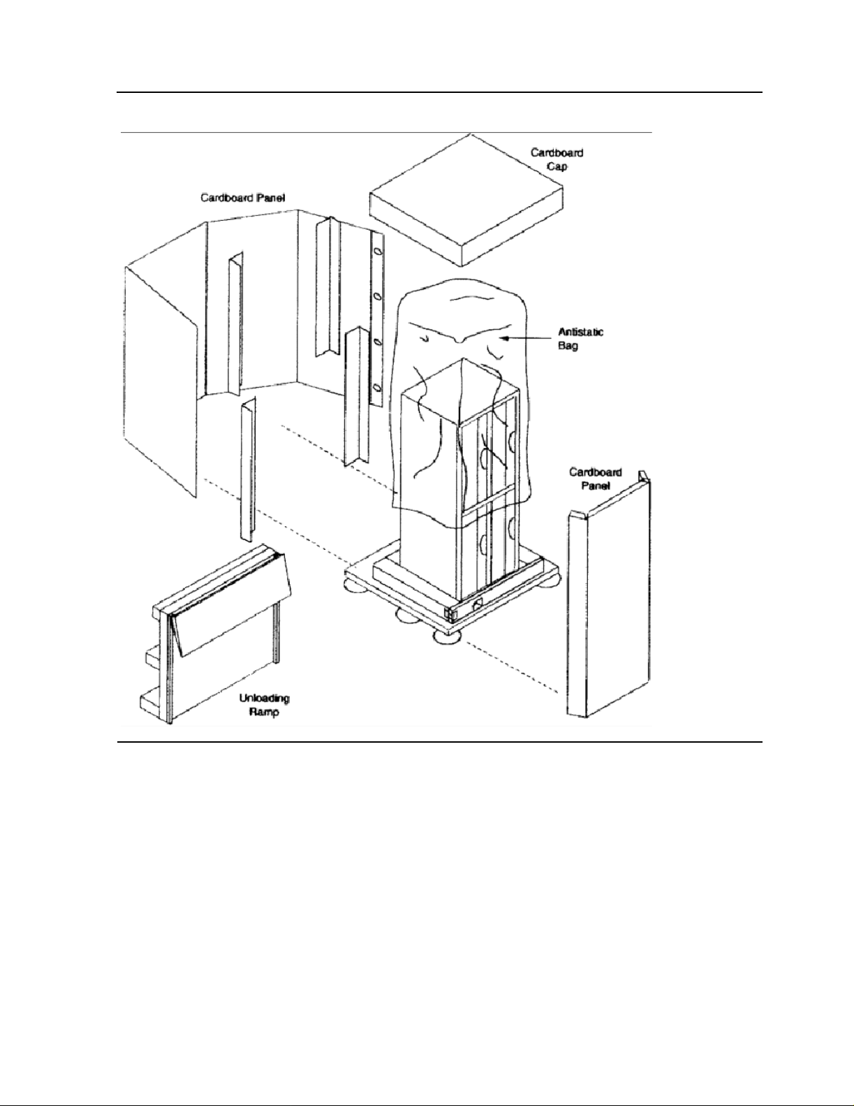
Figure 2-3. Remo ve the Cartons and the Anti-static Bag
00000
00000
00000
00000
00000
00000
00000
00000
00000
00000
00000
00000
00000
00000
00000
00000
00000
00000
00000
00000
00000
00000
00000
00000
00000
00000
00000
00000
00000
00000
00000
00000
00000
00000
00000
00000
0000000000000000000000000000000000000000000000000000000000000000000000000000000000000000000000000000000000000000000000000000000000000000000000000000000000000000000000000000000000000000000000000
0000000000000000000000000000000000000000000000000000000000000000000000000000000000000000000000000000000000000000000000000000000000000000000000000000000000000000000000000000000000000000000000000
0000000000000000000000000000000000000000000000000000000000000000000000000000000000000000000000000000000000000000000000000000000000000000000000000000000000000000000000000000000000000000000000000
0000000000000000000000000000000000000000000000000000000000000000000000000000000000000000000000000000000000000000000000000000000000000000000000000000000000000000000000000000000000000000000000000
0000000000000000000000000000000000000000000000000000000000000000000000000000000000000000000000000000000000000000000000000000000000000000000000000000000000000000000000000000000000000000000000000
0000000000000000000000000000000000000000000000000000000000000000000000000000000000000000000000000000000000000000000000000000000000000000000000000000000000000000000000000000000000000000000000000
0000000000000000000000000000000000000000000000000000000000000000000000000000000000000000000000000000000000000000000000000000000000000000000000000000000000000000000000000000000000000000000000000
0000000000000000000000000000000000000000000000000000000000000000000000000000000000000000000000000000000000000000000000000000000000000000000000000000000000000000000000000000000000000000000000000
0000000000000000000000000000000000000000000000000000000000000000000000000000000000000000000000000000000000000000000000000000000000000000000000000000000000000000000000000000000000000000000000000
0000000000000000000000000000000000000000000000000000000000000000000000000000000000000000000000000000000000000000000000000000000000000000000000000000000000000000000000000000000000000000000000000
0000000000000000000000000000000000000000000000000000000000000000000000000000000000000000000000000000000000000000000000000000000000000000000000000000000000000000000000000000000000000000000000000
0000000000000000000000000000000000000000000000000000000000000000000000000000000000000000000000000000000000000000000000000000000000000000000000000000000000000000000000000000000000000000000000000
0000000000000000000000000000000000000000000000000000000000000000000000000000000000000000000000000000000000000000000000000000000000000000000000000000000000000000000000000000000000000000000000000
0000000000000000000000000000000000000000000000000000000000000000000000000000000000000000000000000000000000000000000000000000000000000000000000000000000000000000000000000000000000000000000000000
0000000000000000000000000000000000000000000000000000000000000000000000000000000000000000000000000000000000000000000000000000000000000000000000000000000000000000000000000000000000000000000000000
0000000000000000000000000000000000000000000000000000000000000000000000000000000000000000000000000000000000000000000000000000000000000000000000000000000000000000000000000000000000000000000000000
0000000000000000000000000000000000000000000000000000000000000000000000000000000000000000000000000000000000000000000000000000000000000000000000000000000000000000000000000000000000000000000000000
0000000000000000000000000000000000000000000000000000000000000000000000000000000000000000000000000000000000000000000000000000000000000000000000000000000000000000000000000000000000000000000000000
0000000000000000000000000000000000000000000000000000000000000000000000000000000000000000000000000000000000000000000000000000000000000000000000000000000000000000000000000000000000000000000000000
0000000000000000000000000000000000000000000000000000000000000000000000000000000000000000000000000000000000000000000000000000000000000000000000000000000000000000000000000000000000000000000000000
0000000000000000000000000000000000000000000000000000000000000000000000000000000000000000000000000000000000000000000000000000000000000000000000000000000000000000000000000000000000000000000000000
0000000000000000000000000000000000000000000000000000000000000000000000000000000000000000000000000000000000000000000000000000000000000000000000000000000000000000000000000000000000000000000000000
0000000000000000000000000000000000000000000000000000000000000000000000000000000000000000000000000000000000000000000000000000000000000000000000000000000000000000000000000000000000000000000000000
0000000000000000000000000000000000000000000000000000000000000000000000000000000000000000000000000000000000000000000000000000000000000000000000000000000000000000000000000000000000000000000000000
0000000000000000000000000000000000000000000000000000000000000000000000000000000000000000000000000000000000000000000000000000000000000000000000000000000000000000000000000000000000000000000000000
0000000000000000000000000000000000000000000000000000000000000000000000000000000000000000000000000000000000000000000000000000000000000000000000000000000000000000000000000000000000000000000000000
0000000000000000000000000000000000000000000000000000000000000000000000000000000000000000000000000000000000000000000000000000000000000000000000000000000000000000000000000000000000000000000000000
0000000000000000000000000000000000000000000000000000000000000000000000000000000000000000000000000000000000000000000000000000000000000000000000000000000000000000000000000000000000000000000000000
0000000000000000000000000000000000000000000000000000000000000000000000000000000000000000000000000000000000000000000000000000000000000000000000000000000000000000000000000000000000000000000000000
0000000000000000000000000000000000000000000000000000000000000000000000000000000000000000000000000000000000000000000000000000000000000000000000000000000000000000000000000000000000000000000000000
0000000000000000000000000000000000000000000000000000000000000000000000000000000000000000000000000000000000000000000000000000000000000000000000000000000000000000000000000000000000000000000000000
0000000000000000000000000000000000000000000000000000000000000000000000000000000000000000000000000000000000000000000000000000000000000000000000000000000000000000000000000000000000000000000000000
0000000000000000000000000000000000000000000000000000000000000000000000000000000000000000000000000000000000000000000000000000000000000000000000000000000000000000000000000000000000000000000000000
0000000000000000000000000000000000000000000000000000000000000000000000000000000000000000000000000000000000000000000000000000000000000000000000000000000000000000000000000000000000000000000000000
0000000000000000000000000000000000000000000000000000000000000000000000000000000000000000000000000000000000000000000000000000000000000000000000000000000000000000000000000000000000000000000000000
0000000000000000000000000000000000000000000000000000000000000000000000000000000000000000000000000000000000000000000000000000000000000000000000000000000000000000000000000000000000000000000000000
5257/5257ACL Installation and User's Guide for NonStop Himalaya S-Series Tape Enclosures—522344-001
-5
Page 22
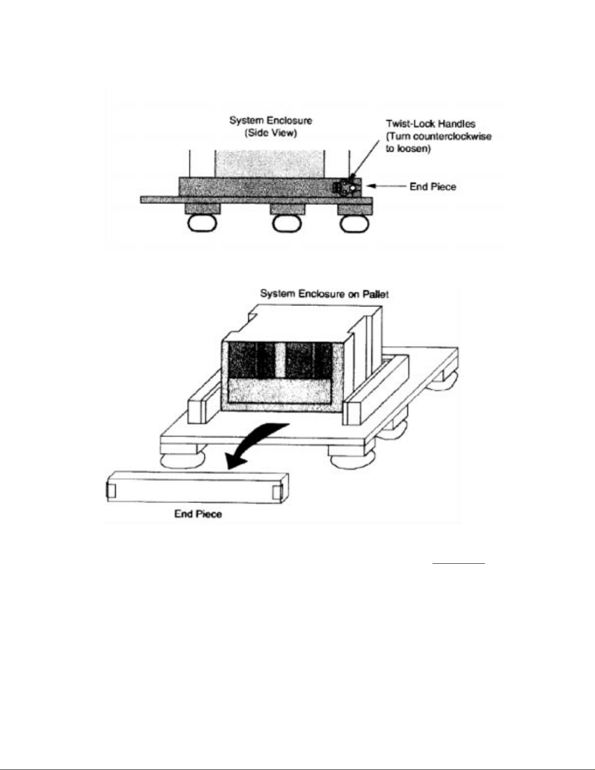
5. Remove the end piece from the bottom of the pallets shown below.
00000
00000
00000
00000
00000
00000
00000
00000
00000
00000
00000
00000
00000
00000
00000
00000
00000
00000
00000
00000
00000
00000
00000
00000
00000
00000
00000
00000
00000
00000
00000
00000
00000
00000
00000
000000000000000000000000000000000000000000000000000000000000000000000000000000000000000000000000000000000000000000000000000000000000000000000000000000000000000000000000000000000000000000000000000000000000000000
000000000000000000000000000000000000000000000000000000000000000000000000000000000000000000000000000000000000000000000000000000000000000000000000000000000000000000000000000000000000000000000000000000000000000000
000000000000000000000000000000000000000000000000000000000000000000000000000000000000000000000000000000000000000000000000000000000000000000000000000000000000000000000000000000000000000000000000000000000000000000
000000000000000000000000000000000000000000000000000000000000000000000000000000000000000000000000000000000000000000000000000000000000000000000000000000000000000000000000000000000000000000000000000000000000000000
000000000000000000000000000000000000000000000000000000000000000000000000000000000000000000000000000000000000000000000000000000000000000000000000000000000000000000000000000000000000000000000000000000000000000000
000000000000000000000000000000000000000000000000000000000000000000000000000000000000000000000000000000000000000000000000000000000000000000000000000000000000000000000000000000000000000000000000000000000000000000
000000000000000000000000000000000000000000000000000000000000000000000000000000000000000000000000000000000000000000000000000000000000000000000000000000000000000000000000000000000000000000000000000000000000000000
000000000000000000000000000000000000000000000000000000000000000000000000000000000000000000000000000000000000000000000000000000000000000000000000000000000000000000000000000000000000000000000000000000000000000000
000000000000000000000000000000000000000000000000000000000000000000000000000000000000000000000000000000000000000000000000000000000000000000000000000000000000000000000000000000000000000000000000000000000000000000
000000000000000000000000000000000000000000000000000000000000000000000000000000000000000000000000000000000000000000000000000000000000000000000000000000000000000000000000000000000000000000000000000000000000000000
000000000000000000000000000000000000000000000000000000000000000000000000000000000000000000000000000000000000000000000000000000000000000000000000000000000000000000000000000000000000000000000000000000000000000000
000000000000000000000000000000000000000000000000000000000000000000000000000000000000000000000000000000000000000000000000000000000000000000000000000000000000000000000000000000000000000000000000000000000000000000
000000000000000000000000000000000000000000000000000000000000000000000000000000000000000000000000000000000000000000000000000000000000000000000000000000000000000000000000000000000000000000000000000000000000000000
000000000000000000000000000000000000000000000000000000000000000000000000000000000000000000000000000000000000000000000000000000000000000000000000000000000000000000000000000000000000000000000000000000000000000000
000000000000000000000000000000000000000000000000000000000000000000000000000000000000000000000000000000000000000000000000000000000000000000000000000000000000000000000000000000000000000000000000000000000000000000
000000000000000000000000000000000000000000000000000000000000000000000000000000000000000000000000000000000000000000000000000000000000000000000000000000000000000000000000000000000000000000
000000000000000000000000000000000000000000000000000000000000000000000000000000000000000000000000000000000000000000000000000000000000000000000000000000000000000000000000000000000000000000
000000000000000000000000000000000000000000000000000000000000000000000000000000000000000000000000000000000000000000000000000000000000000000000000000000000000000000000000000000000000000000
000000000000000000000000000000000000000000000000000000000000000000000000000000000000000000000000000000000000000000000000000000000000000000000000000000000000000000000000000000000000000000
000000000000000000000000000000000000000000000000000000000000000000000000000000000000000000000000000000000000000000000000000000000000000000000000000000000000000000000000000000000000000000
000000000000000000000000000000000000000000000000000000000000000000000000000000000000000000000000000000000000000000000000000000000000000000000000000000000000000000000000000000000000000000
000000000000000000000000000000000000000000000000000000000000000000000000000000000000000000000000000000000000000000000000000000000000000000000000000000000000000000000000000000000000000000
000000000000000000000000000000000000000000000000000000000000000000000000000000000000000000000000000000000000000000000000000000000000000000000000000000000000000000000000000000000000000000
000000000000000000000000000000000000000000000000000000000000000000000000000000000000000000000000000000000000000000000000000000000000000000000000000000000000000000000000000000000000000000
000000000000000000000000000000000000000000000000000000000000000000000000000000000000000000000000000000000000000000000000000000000000000000000000000000000000000000000000000000000000000000
000000000000000000000000000000000000000000000000000000000000000000000000000000000000000000000000000000000000000000000000000000000000000000000000000000000000000000000000000000000000000000
000000000000000000000000000000000000000000000000000000000000000000000000000000000000000000000000000000000000000000000000000000000000000000000000000000000000000000000000000000000000000000
000000000000000000000000000000000000000000000000000000000000000000000000000000000000000000000000000000000000000000000000000000000000000000000000000000000000000000000000000000000000000000
000000000000000000000000000000000000000000000000000000000000000000000000000000000000000000000000000000000000000000000000000000000000000000000000000000000000000000000000000000000000000000
000000000000000000000000000000000000000000000000000000000000000000000000000000000000000000000000000000000000000000000000000000000000000000000000000000000000000000000000000000000000000000
000000000000000000000000000000000000000000000000000000000000000000000000000000000000000000000000000000000000000000000000000000000000000000000000000000000000000000000000000000000000000000
000000000000000000000000000000000000000000000000000000000000000000000000000000000000000000000000000000000000000000000000000000000000000000000000000000000000000000000000000000000000000000
000000000000000000000000000000000000000000000000000000000000000000000000000000000000000000000000000000000000000000000000000000000000000000000000000000000000000000000000000000000000000000
000000000000000000000000000000000000000000000000000000000000000000000000000000000000000000000000000000000000000000000000000000000000000000000000000000000000000000000000000000000000000000
000000000000000000000000000000000000000000000000000000000000000000000000000000000000000000000000000000000000000000000000000000000000000000000000000000000000000000000000000000000000000000
6. Push the tall end of the ramp against the pallet to form an incline. Insert the bolts in
their predrilled holes to secure the ramp to the pallet as shown in Fig ure 2-4
5257/5257ACL Installation and User's Guide for NonStop Himalaya S-Series Tape Enclosures—522344-001
-6
.
Page 23
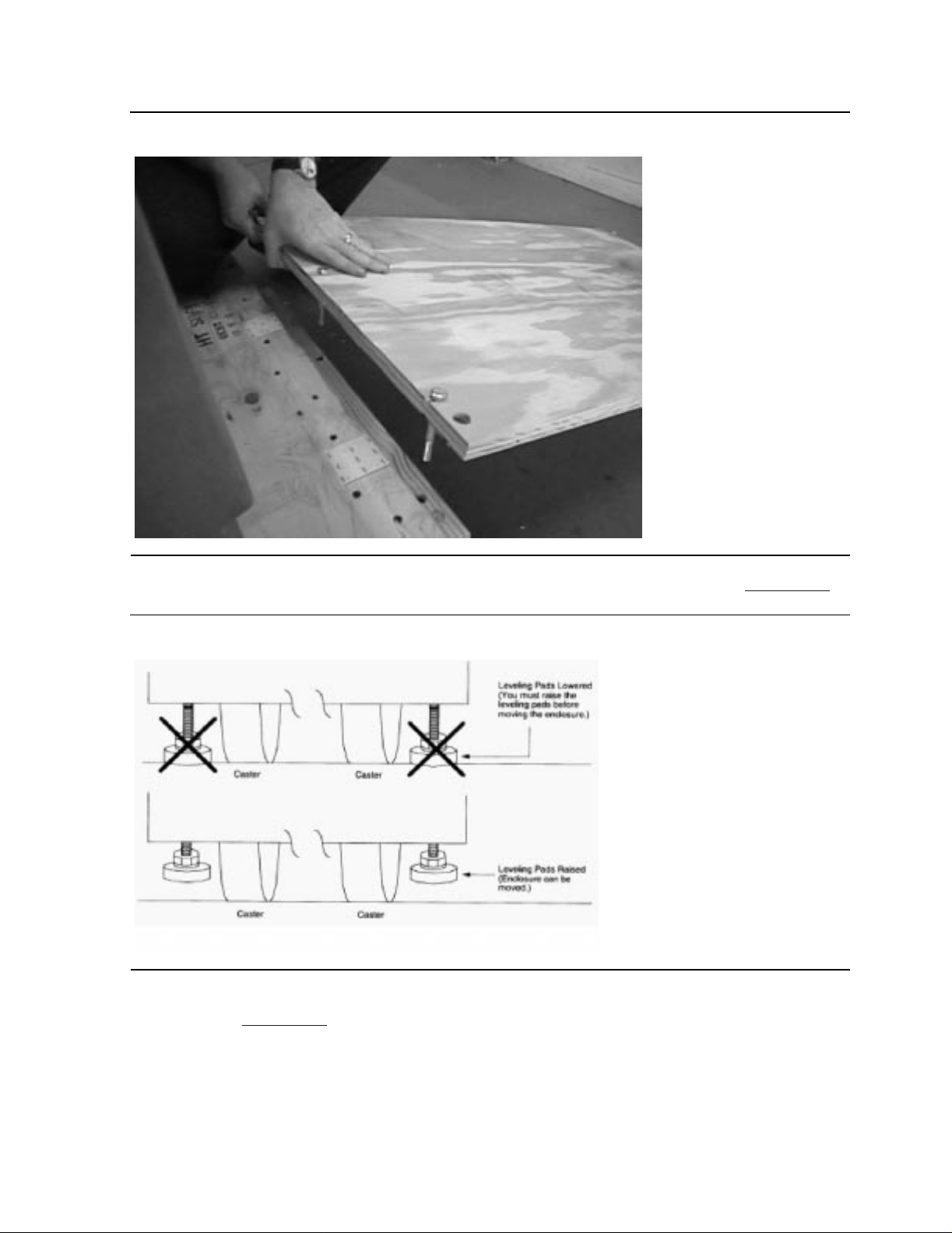
Figure 2-4. The Ramp Being Placed on the Pallet
00000
00000
00000
00000
00000
00000
00000
00000
00000
00000
00000
00000
00000
00000
00000
00000
00000
00000
00000
00000
00000
00000
00000
00000
00000
00000
00000
00000
00000
00000
00000
00000
00000
00000
00000
000000000000000000000000000000000000000000000000000000000000000000000000000000000000000000000000000000000000000000000000000000000000000000000000000000000000000000000
000000000000000000000000000000000000000000000000000000000000000000000000000000000000000000000000000000000000000000000000000000000000000000000000000000000000000000000
000000000000000000000000000000000000000000000000000000000000000000000000000000000000000000000000000000000000000000000000000000000000000000000000000000000000000000000
000000000000000000000000000000000000000000000000000000000000000000000000000000000000000000000000000000000000000000000000000000000000000000000000000000000000000000000
000000000000000000000000000000000000000000000000000000000000000000000000000000000000000000000000000000000000000000000000000000000000000000000000000000000000000000000
000000000000000000000000000000000000000000000000000000000000000000000000000000000000000000000000000000000000000000000000000000000000000000000000000000000000000000000
000000000000000000000000000000000000000000000000000000000000000000000000000000000000000000000000000000000000000000000000000000000000000000000000000000000000000000000
000000000000000000000000000000000000000000000000000000000000000000000000000000000000000000000000000000000000000000000000000000000000000000000000000000000000000000000
000000000000000000000000000000000000000000000000000000000000000000000000000000000000000000000000000000000000000000000000000000000000000000000000000000000000000000000
000000000000000000000000000000000000000000000000000000000000000000000000000000000000000000000000000000000000000000000000000000000000000000000000000000000000000000000
000000000000000000000000000000000000000000000000000000000000000000000000000000000000000000000000000000000000000000000000000000000000000000000000000000000000000000000
000000000000000000000000000000000000000000000000000000000000000000000000000000000000000000000000000000000000000000000000000000000000000000000000000000000000000000000
000000000000000000000000000000000000000000000000000000000000000000000000000000000000000000000000000000000000000000000000000000000000000000000000000000000000000000000
000000000000000000000000000000000000000000000000000000000000000000000000000000000000000000000000000000000000000000000000000000000000000000000000000000000000000000000
000000000000000000000000000000000000000000000000000000000000000000000000000000000000000000000000000000000000000000000000000000000000000000000000000000000000000000000
000000000000000000000000000000000000000000000000000000000000000000000000000000000000000000000000000000000000000000000000000000000000000000000000000000000000000000000
000000000000000000000000000000000000000000000000000000000000000000000000000000000000000000000000000000000000000000000000000000000000000000000000000000000000000000000
000000000000000000000000000000000000000000000000000000000000000000000000000000000000000000000000000000000000000000000000000000000000000000000000000000000000000000000
000000000000000000000000000000000000000000000000000000000000000000000000000000000000000000000000000000000000000000000000000000000000000000000000000000000000000000000
000000000000000000000000000000000000000000000000000000000000000000000000000000000000000000000000000000000000000000000000000000000000000000000000000000000000000000000
7. Check the leveling pads before moving the enclosure stack as shown in Figure 2-5.
Figure 2-5. The Operation of the Leveling Pads
000000000000000000000000000000000000000000000000000000000000000000000000000000000000000000000000000000000000000000000000000000000000000000000000000000
000000000000000000000000000000000000000000000000000000000000000000000000000000000000000000000000000000000000000000000000000000000000000000000000000000
000000000000000000000000000000000000000000000000000000000000000000000000000000000000000000000000000000000000000000000000000000000000000000000000000000
000000000000000000000000000000000000000000000000000000000000000000000000000000000000000000000000000000000000000000000000000000000000000000000000000000
000000000000000000000000000000000000000000000000000000000000000000000000000000000000000000000000000000000000000000000000000000000000000000000000000000
000000000000000000000000000000000000000000000000000000000000000000000000000000000000000000000000000000000000000000000000000000000000000000000000000000
000000000000000000000000000000000000000000000000000000000000000000000000000000000000000000000000000000000000000000000000000000000000000000000000000000
000000000000000000000000000000000000000000000000000000000000000000000000000000000000000000000000000000000000000000000000000000000000000000000000000000
000000000000000000000000000000000000000000000000000000000000000000000000000000000000000000000000000000000000000000000000000000000000000000000000000000
000000000000000000000000000000000000000000000000000000000000000000000000000000000000000000000000000000000000000000000000000000000000000000000000000000
000000000000000000000000000000000000000000000000000000000000000000000000000000000000000000000000000000000000000000000000000000000000000000000000000000
000000000000000000000000000000000000000000000000000000000000000000000000000000000000000000000000000000000000000000000000000000000000000000000000000000
000000000000000000000000000000000000000000000000000000000000000000000000000000000000000000000000000000000000000000000000000000000000000000000000000000
000000000000000000000000000000000000000000000000000000000000000000000000000000000000000000000000000000000000000000000000000000000000000000000000000000
000000000000000000000000000000000000000000000000000000000000000000000000000000000000000000000000000000000000000000000000000000000000000000000000000000
8. With one person on each side of the tape enclosure, slowly guide it off the pallet as
shown in Figure 2-6
) The platforms are on casters, allowing the enclosure to be
moved easily down the ramp and into position for inspection.
5257/5257ACL Installation and User's Guide for NonStop Himalaya S-Series Tape Enclosures—522344-001
-7
Page 24

5257/5257ACL Installation and User's Guide for NonStop Himalaya S-Series Tape Enclosures—522344-001
-8
Page 25
Unpacking and Installing the T ape Enclosures
00000
00000
00000
00000
00000
00000
00000
00000
00000
00000
00000
00000
00000
00000
00000
00000
00000
00000
00000
00000
00000
00000
00000
00000
00000
00000
00000
00000
2 Unpacking and Installing the Tape Enclosures 2 Unpacking and Installing the Tape Enclosures
Figure 2-6. Unloading the Platform
00000000000000000000000000000000000000000000000000000000000000000000000000000000000000000000000000000000000000000000000000000000000000000000000000000000000000000000000000000000000000000000000000000000
00000000000000000000000000000000000000000000000000000000000000000000000000000000000000000000000000000000000000000000000000000000000000000000000000000000000000000000000000000000000000000000000000000000
00000000000000000000000000000000000000000000000000000000000000000000000000000000000000000000000000000000000000000000000000000000000000000000000000000000000000000000000000000000000000000000000000000000
00000000000000000000000000000000000000000000000000000000000000000000000000000000000000000000000000000000000000000000000000000000000000000000000000000000000000000000000000000000000000000000000000000000
00000000000000000000000000000000000000000000000000000000000000000000000000000000000000000000000000000000000000000000000000000000000000000000000000000000000000000000000000000000000000000000000000000000
00000000000000000000000000000000000000000000000000000000000000000000000000000000000000000000000000000000000000000000000000000000000000000000000000000000000000000000000000000000000000000000000000000000
00000000000000000000000000000000000000000000000000000000000000000000000000000000000000000000000000000000000000000000000000000000000000000000000000000000000000000000000000000000000000000000000000000000
00000000000000000000000000000000000000000000000000000000000000000000000000000000000000000000000000000000000000000000000000000000000000000000000000000000000000000000000000000000000000000000000000000000
00000000000000000000000000000000000000000000000000000000000000000000000000000000000000000000000000000000000000000000000000000000000000000000000000000000000000000000000000000000000000000000000000000000
00000000000000000000000000000000000000000000000000000000000000000000000000000000000000000000000000000000000000000000000000000000000000000000000000000000000000000000000000000000000000000000000000000000
00000000000000000000000000000000000000000000000000000000000000000000000000000000000000000000000000000000000000000000000000000000000000000000000000000000000000000000000000000000000000000000000000000000
00000000000000000000000000000000000000000000000000000000000000000000000000000000000000000000000000000000000000000000000000000000000000000000000000000000000000000000000000000000000000000000000000000000
00000000000000000000000000000000000000000000000000000000000000000000000000000000000000000000000000000000000000000000000000000000000000000000000000000000000000000000000000000000000000000000000000000000
00000000000000000000000000000000000000000000000000000000000000000000000000000000000000000000000000000000000000000000000000000000000000000000000000000000000000000000000000000000000000000000000000000000
00000000000000000000000000000000000000000000000000000000000000000000000000000000000000000000000000000000000000000000000000000000000000000000000000000000000000000000000000000000000000000000000000000000
00000000000000000000000000000000000000000000000000000000000000000000000000000000000000000000000000000000000000000000000000000000000000000000000000000000000000000000000000000000000000000000000000000000
00000000000000000000000000000000000000000000000000000000000000000000000000000000000000000000000000000000000000000000000000000000000000000000000000000000000000000000000000000000000000000000000000000000
00000000000000000000000000000000000000000000000000000000000000000000000000000000000000000000000000000000000000000000000000000000000000000000000000000000000000000000000000000000000000000000000000000000
00000000000000000000000000000000000000000000000000000000000000000000000000000000000000000000000000000000000000000000000000000000000000000000000000000000000000000000000000000000000000000000000000000000
00000000000000000000000000000000000000000000000000000000000000000000000000000000000000000000000000000000000000000000000000000000000000000000000000000000000000000000000000000000000000000000000000000000
00000000000000000000000000000000000000000000000000000000000000000000000000000000000000000000000000000000000000000000000000000000000000000000000000000000000000000000000000000000000000000000000000000000
00000000000000000000000000000000000000000000000000000000000000000000000000000000000000000000000000000000000000000000000000000000000000000000000000000000000000000000000000000000000000000000000000000000
00000000000000000000000000000000000000000000000000000000000000000000000000000000000000000000000000000000000000000000000000000000000000000000000000000000000000000000000000000000000000000000000000000000
00000000000000000000000000000000000000000000000000000000000000000000000000000000000000000000000000000000000000000000000000000000000000000000000000000000000000000000000000000000000000000000000000000000
00000000000000000000000000000000000000000000000000000000000000000000000000000000000000000000000000000000000000000000000000000000000000000000000000000000000000000000000000000000000000000000000000000000
00000000000000000000000000000000000000000000000000000000000000000000000000000000000000000000000000000000000000000000000000000000000000000000000000000000000000000000000000000000000000000000000000000000
00000000000000000000000000000000000000000000000000000000000000000000000000000000000000000000000000000000000000000000000000000000000000000000000000000000000000000000000000000000000000000000000000000000
00000000000000000000000000000000000000000000000000000000000000000000000000000000000000000000000000000000000000000000000000000000000000000000000000000000000000000000000000000000000000000000000000000000
a. Inspect for scratches, rust, or shipping damage.
b. Check that these items are present:
The 5257/5257ACL User’s Kit Box, containing data cartridge, power cord,
°
user’s manual, and reference card
A box containing a copper cable for each drive to be connected to the
°
S-SAC or PMF/IOMF
Note. Record any damage on the waybill. Report any damaged equipment to
Compaq. Failure to report damaged equipment immediately can result in the loss of a
claim.
5257/5257ACL Installation and User's Guide for NonStop Himalaya S-Series Tape Enclosures—522344-001
2-9
Page 26
Unpacking and Installing the T ape Enclosures
00000
00000
00000
00000
00000
00000
00000
00000
00000
00000
00000
00000
00000
Suggested Tape Enclosure Configuratio n Options
Suggested Tape Enclosure Configuration Options
Two tape enclosures can be stacked on each oth er. If two tape enclosures are stacked, the
bottom shelf in the bottom enclosure must be left empty.
A tape enclosure can be stacked on top of a system enclosure as shown in Figure 2-7
.
All three shelves can be used in the enclosure.
Figure 2-7. Tape Enclosure on Server
000000000000000000000000000000000000000000000000000000000000000000000000000000000000000000000000000000000000000000000
000000000000000000000000000000000000000000000000000000000000000000000000000000000000000000000000000000000000000000000
000000000000000000000000000000000000000000000000000000000000000000000000000000000000000000000000000000000000000000000
000000000000000000000000000000000000000000000000000000000000000000000000000000000000000000000000000000000000000000000
000000000000000000000000000000000000000000000000000000000000000000000000000000000000000000000000000000000000000000000
000000000000000000000000000000000000000000000000000000000000000000000000000000000000000000000000000000000000000000000
000000000000000000000000000000000000000000000000000000000000000000000000000000000000000000000000000000000000000000000
000000000000000000000000000000000000000000000000000000000000000000000000000000000000000000000000000000000000000000000
000000000000000000000000000000000000000000000000000000000000000000000000000000000000000000000000000000000000000000000
000000000000000000000000000000000000000000000000000000000000000000000000000000000000000000000000000000000000000000000
000000000000000000000000000000000000000000000000000000000000000000000000000000000000000000000000000000000000000000000
000000000000000000000000000000000000000000000000000000000000000000000000000000000000000000000000000000000000000000000
000000000000000000000000000000000000000000000000000000000000000000000000000000000000000000000000000000000000000000000
5257/5257ACL Installation and User's Guide for NonStop Himalaya S-Series Tape Enclosures—522344-001
2-10
Page 27
Unpacking and Installing the T ape Enclosures
00000
00000
00000
00000
00000
00000
00000
00000
00000
00000
00000
00000
00000
00000
00000
00000
00000
00000
Tape Enclosure Configuration Hazards
Tape Enclosur e Configuration Hazards
WARNING. Do not stack a system enclosure on a tape enclosure. The server is heavier than
the tape enclosure, and stacking it on top of the tape enclosure causes the unit to be unstable
as shown in Figure 2-8
Figure 2-8. Server on Tape Enclosure
00000000000000000000000000000000000000000000000000000000000000000000000000000000000000000000000000000
00000000000000000000000000000000000000000000000000000000000000000000000000000000000000000000000000000
00000000000000000000000000000000000000000000000000000000000000000000000000000000000000000000000000000
00000000000000000000000000000000000000000000000000000000000000000000000000000000000000000000000000000
00000000000000000000000000000000000000000000000000000000000000000000000000000000000000000000000000000
00000000000000000000000000000000000000000000000000000000000000000000000000000000000000000000000000000
00000000000000000000000000000000000000000000000000000000000000000000000000000000000000000000000000000
00000000000000000000000000000000000000000000000000000000000000000000000000000000000000000000000000000
00000000000000000000000000000000000000000000000000000000000000000000000000000000000000000000000000000
00000000000000000000000000000000000000000000000000000000000000000000000000000000000000000000000000000
00000000000000000000000000000000000000000000000000000000000000000000000000000000000000000000000000000
00000000000000000000000000000000000000000000000000000000000000000000000000000000000000000000000000000
00000000000000000000000000000000000000000000000000000000000000000000000000000000000000000000000000000
00000000000000000000000000000000000000000000000000000000000000000000000000000000000000000000000000000
00000000000000000000000000000000000000000000000000000000000000000000000000000000000000000000000000000
00000000000000000000000000000000000000000000000000000000000000000000000000000000000000000000000000000
00000000000000000000000000000000000000000000000000000000000000000000000000000000000000000000000000000
00000000000000000000000000000000000000000000000000000000000000000000000000000000000000000000000000000
.
Tape Enclosur e Dimensions and Configurat io ns
Height Bottom enclosure
(including casters)
Stackable enclosure
(no casters)
Caster 1.75 inches
Drive space 8 inches
Width Front and back side 22.50 inches
Drive space 17.50 inches
Depth Outside of enclosure 30.50 inches
For an illustration of the dimensions, see Figure 2-9.
5257/5257ACL Installation and User's Guide for NonStop Himalaya S-Series Tape Enclosures—522344-001
2-11
34 inches
32.25 inches
Page 28
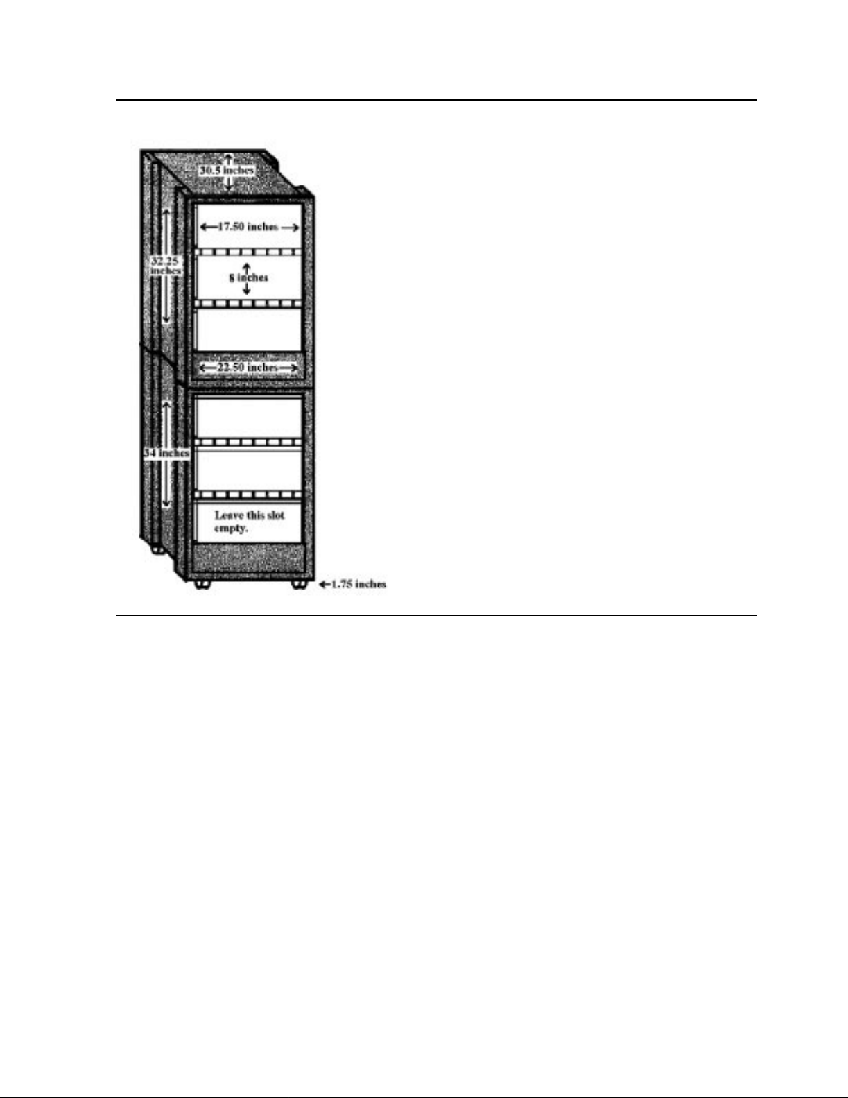
Unpacking and Installing the T ape Enclosures
00000
00000
00000
00000
00000
00000
00000
00000
00000
00000
00000
00000
00000
00000
00000
00000
00000
00000
00000
00000
00000
00000
00000
00000
00000
00000
00000
00000
Figure 2-9. Dimensions of the Base and Stackable Tape Enclosure
000000000000000000000000000000000000000000000000000000000000000000000000000000000000000000000000000
000000000000000000000000000000000000000000000000000000000000000000000000000000000000000000000000000
000000000000000000000000000000000000000000000000000000000000000000000000000000000000000000000000000
000000000000000000000000000000000000000000000000000000000000000000000000000000000000000000000000000
000000000000000000000000000000000000000000000000000000000000000000000000000000000000000000000000000
000000000000000000000000000000000000000000000000000000000000000000000000000000000000000000000000000
000000000000000000000000000000000000000000000000000000000000000000000000000000000000000000000000000
000000000000000000000000000000000000000000000000000000000000000000000000000000000000000000000000000
000000000000000000000000000000000000000000000000000000000000000000000000000000000000000000000000000
000000000000000000000000000000000000000000000000000000000000000000000000000000000000000000000000000
000000000000000000000000000000000000000000000000000000000000000000000000000000000000000000000000000
000000000000000000000000000000000000000000000000000000000000000000000000000000000000000000000000000
000000000000000000000000000000000000000000000000000000000000000000000000000000000000000000000000000
000000000000000000000000000000000000000000000000000000000000000000000000000000000000000000000000000
000000000000000000000000000000000000000000000000000000000000000000000000000000000000000000000000000
000000000000000000000000000000000000000000000000000000000000000000000000000000000000000000000000000
000000000000000000000000000000000000000000000000000000000000000000000000000000000000000000000000000
000000000000000000000000000000000000000000000000000000000000000000000000000000000000000000000000000
000000000000000000000000000000000000000000000000000000000000000000000000000000000000000000000000000
000000000000000000000000000000000000000000000000000000000000000000000000000000000000000000000000000
000000000000000000000000000000000000000000000000000000000000000000000000000000000000000000000000000
000000000000000000000000000000000000000000000000000000000000000000000000000000000000000000000000000
000000000000000000000000000000000000000000000000000000000000000000000000000000000000000000000000000
000000000000000000000000000000000000000000000000000000000000000000000000000000000000000000000000000
000000000000000000000000000000000000000000000000000000000000000000000000000000000000000000000000000
000000000000000000000000000000000000000000000000000000000000000000000000000000000000000000000000000
000000000000000000000000000000000000000000000000000000000000000000000000000000000000000000000000000
000000000000000000000000000000000000000000000000000000000000000000000000000000000000000000000000000
Base Tape Enclosure
Base Tape Enclosure
Only the top two shelves in the base tape enclosure are usable. The bottom shelf should
remain empty. The base tape enclosure can store up to two 5257ACL drives or four
5257 drives. A combination of both drives can be stored in the enclosure. The bottom
shelf of the base tape enclosure should remain empty.
S tackable Tape Enclosur e
All three shelves in the stackable tape enclosure are usable and can have the same drive
configurations as the base tape enclosure. The stackable tape enclosure can hold up to
six 5257 tape drives or three 5257ACL drives. A combination of both drives may be
stored in the enclosure. To stack enclosures, contact your service provider . Instructions
are located in the Himalaya S-Series Service Provider Supplement.
5257/5257ACL Installation and User's Guide for NonStop Himalaya S-Series Tape Enclosures—522344-001
2-12
Page 29

Unpacking and Installing the T ape Enclosures
00000
00000
00000
00000
00000
00000
00000
00000
00000
00000
00000
00000
00000
00000
00000
00000
00000
00000
00000
00000
00000
00000
00000
00000
00000
00000
00000
00000
00000
00000
00000
Tape Enclosure Rear Cover
Tape Enclosure Rear Cover
The rear cover of the tape enclosure needs to be attached. Figure 2-10 shows a picture of
the rear cover installed onto the tape enclosure to cover the power cords and cabling.
Figure 2-10. Tape Enclosure with a Rear Cover Attached
00000000000000000000000000000000000000000000000000000000000000000000000000000000000000000000000000000000000000000000000000000000000000000000000000000000000000000000000000000000000000000000000000000000000000000000000000000000
00000000000000000000000000000000000000000000000000000000000000000000000000000000000000000000000000000000000000000000000000000000000000000000000000000000000000000000000000000000000000000000000000000000000000000000000000000000
00000000000000000000000000000000000000000000000000000000000000000000000000000000000000000000000000000000000000000000000000000000000000000000000000000000000000000000000000000000000000000000000000000000000000000000000000000000
00000000000000000000000000000000000000000000000000000000000000000000000000000000000000000000000000000000000000000000000000000000000000000000000000000000000000000000000000000000000000000000000000000000000000000000000000000000
00000000000000000000000000000000000000000000000000000000000000000000000000000000000000000000000000000000000000000000000000000000000000000000000000000000000000000000000000000000000000000000000000000000000000000000000000000000
00000000000000000000000000000000000000000000000000000000000000000000000000000000000000000000000000000000000000000000000000000000000000000000000000000000000000000000000000000000000000000000000000000000000000000000000000000000
00000000000000000000000000000000000000000000000000000000000000000000000000000000000000000000000000000000000000000000000000000000000000000000000000000000000000000000000000000000000000000000000000000000000000000000000000000000
00000000000000000000000000000000000000000000000000000000000000000000000000000000000000000000000000000000000000000000000000000000000000000000000000000000000000000000000000000000000000000000000000000000000000000000000000000000
00000000000000000000000000000000000000000000000000000000000000000000000000000000000000000000000000000000000000000000000000000000000000000000000000000000000000000000000000000000000000000000000000000000000000000000000000000000
00000000000000000000000000000000000000000000000000000000000000000000000000000000000000000000000000000000000000000000000000000000000000000000000000000000000000000000000000000000000000000000000000000000000000000000000000000000
00000000000000000000000000000000000000000000000000000000000000000000000000000000000000000000000000000000000000000000000000000000000000000000000000000000000000000000000000000000000000000000000000000000000000000000000000000000
00000000000000000000000000000000000000000000000000000000000000000000000000000000000000000000000000000000000000000000000000000000000000000000000000000000000000000000000000000000000000000000000000000000000000000000000000000000
00000000000000000000000000000000000000000000000000000000000000000000000000000000000000000000000000000000000000000000000000000000000000000000000000000000000000000000000000000000000000000000000000000000000000000000000000000000
00000000000000000000000000000000000000000000000000000000000000000000000000000000000000000000000000000000000000000000000000000000000000000000000000000000000000000000000000000000000000000000000000000000000000000000000000000000
00000000000000000000000000000000000000000000000000000000000000000000000000000000000000000000000000000000000000000000000000000000000000000000000000000000000000000000000000000000000000000000000000000000000000000000000000000000
00000000000000000000000000000000000000000000000000000000000000000000000000000000000000000000000000000000000000000000000000000000000000000000000000000000000000000000000000000000000000000000000000000000000000000000000000000000
00000000000000000000000000000000000000000000000000000000000000000000000000000000000000000000000000000000000000000000000000000000000000000000000000000000000000000000000000000000000000000000000000000000000000000000000000000000
00000000000000000000000000000000000000000000000000000000000000000000000000000000000000000000000000000000000000000000000000000000000000000000000000000000000000000000000000000000000000000000000000000000000000000000000000000000
00000000000000000000000000000000000000000000000000000000000000000000000000000000000000000000000000000000000000000000000000000000000000000000000000000000000000000000000000000000000000000000000000000000000000000000000000000000
00000000000000000000000000000000000000000000000000000000000000000000000000000000000000000000000000000000000000000000000000000000000000000000000000000000000000000000000000000000000000000000000000000000000000000000000000000000
00000000000000000000000000000000000000000000000000000000000000000000000000000000000000000000000000000000000000000000000000000000000000000000000000000000000000000000000000000000000000000000000000000000000000000000000000000000
00000000000000000000000000000000000000000000000000000000000000000000000000000000000000000000000000000000000000000000000000000000000000000000000000000000000000000000000000000000000000000000000000000000000000000000000000000000
00000000000000000000000000000000000000000000000000000000000000000000000000000000000000000000000000000000000000000000000000000000000000000000000000000000000000000000000000000000000000000000000000000000000000000000000000000000
00000000000000000000000000000000000000000000000000000000000000000000000000000000000000000000000000000000000000000000000000000000000000000000000000000000000000000000000000000000000000000000000000000000000000000000000000000000
00000000000000000000000000000000000000000000000000000000000000000000000000000000000000000000000000000000000000000000000000000000000000000000000000000000000000000000000000000000000000000000000000000000000000000000000000000000
00000000000000000000000000000000000000000000000000000000000000000000000000000000000000000000000000000000000000000000000000000000000000000000000000000000000000000000000000000000000000000000000000000000000000000000000000000000
00000000000000000000000000000000000000000000000000000000000000000000000000000000000000000000000000000000000000000000000000000000000000000000000000000000000000000000000000000000000000000000000000000000000000000000000000000000
00000000000000000000000000000000000000000000000000000000000000000000000000000000000000000000000000000000000000000000000000000000000000000000000000000000000000000000000000000000000000000000000000000000000000000000000000000000
00000000000000000000000000000000000000000000000000000000000000000000000000000000000000000000000000000000000000000000000000000000000000000000000000000000000000000000000000000000000000000000000000000000000000000000000000000000
00000000000000000000000000000000000000000000000000000000000000000000000000000000000000000000000000000000000000000000000000000000000000000000000000000000000000000000000000000000000000000000000000000000000000000000000000000000
00000000000000000000000000000000000000000000000000000000000000000000000000000000000000000000000000000000000000000000000000000000000000000000000000000000000000000000000000000000000000000000000000000000000000000000000000000000
5257/5257ACL Installation and User's Guide for NonStop Himalaya S-Series Tape Enclosures—522344-001
2-13
Page 30

Unpacking and Installing the T ape Enclosures
00000
00000
00000
00000
00000
00000
00000
00000
00000
00000
00000
00000
00000
00000
00000
00000
00000
00000
00000
00000
00000
00000
00000
Installing the 5257/5257ACL Tape Drives
The rear cover is shipped with four push-button rivets. Figure 2-11 shows a picture of
the push-button rivets.
Figure 2-11. Push-Button Rivets
00000000000000000000000000000000000000000000000000000000000000000000000000000000000000000000000000000000000000000000000000000000000000000000000000000000000000000000
00000000000000000000000000000000000000000000000000000000000000000000000000000000000000000000000000000000000000000000000000000000000000000000000000000000000000000000
00000000000000000000000000000000000000000000000000000000000000000000000000000000000000000000000000000000000000000000000000000000000000000000000000000000000000000000
00000000000000000000000000000000000000000000000000000000000000000000000000000000000000000000000000000000000000000000000000000000000000000000000000000000000000000000
00000000000000000000000000000000000000000000000000000000000000000000000000000000000000000000000000000000000000000000000000000000000000000000000000000000000000000000
00000000000000000000000000000000000000000000000000000000000000000000000000000000000000000000000000000000000000000000000000000000000000000000000000000000000000000000
00000000000000000000000000000000000000000000000000000000000000000000000000000000000000000000000000000000000000000000000000000000000000000000000000000000000000000000
00000000000000000000000000000000000000000000000000000000000000000000000000000000000000000000000000000000000000000000000000000000000000000000000000000000000000000000
00000000000000000000000000000000000000000000000000000000000000000000000000000000000000000000000000000000000000000000000000000000000000000000000000000000000000000000
00000000000000000000000000000000000000000000000000000000000000000000000000000000000000000000000000000000000000000000000000000000000000000000000000000000000000000000
00000000000000000000000000000000000000000000000000000000000000000000000000000000000000000000000000000000000000000000000000000000000000000000000000000000000000000000
00000000000000000000000000000000000000000000000000000000000000000000000000000000000000000000000000000000000000000000000000000000000000000000000000000000000000000000
00000000000000000000000000000000000000000000000000000000000000000000000000000000000000000000000000000000000000000000000000000000000000000000000000000000000000000000
00000000000000000000000000000000000000000000000000000000000000000000000000000000000000000000000000000000000000000000000000000000000000000000000000000000000000000000
00000000000000000000000000000000000000000000000000000000000000000000000000000000000000000000000000000000000000000000000000000000000000000000000000000000000000000000
00000000000000000000000000000000000000000000000000000000000000000000000000000000000000000000000000000000000000000000000000000000000000000000000000000000000000000000
00000000000000000000000000000000000000000000000000000000000000000000000000000000000000000000000000000000000000000000000000000000000000000000000000000000000000000000
00000000000000000000000000000000000000000000000000000000000000000000000000000000000000000000000000000000000000000000000000000000000000000000000000000000000000000000
00000000000000000000000000000000000000000000000000000000000000000000000000000000000000000000000000000000000000000000000000000000000000000000000000000000000000000000
00000000000000000000000000000000000000000000000000000000000000000000000000000000000000000000000000000000000000000000000000000000000000000000000000000000000000000000
00000000000000000000000000000000000000000000000000000000000000000000000000000000000000000000000000000000000000000000000000000000000000000000000000000000000000000000
00000000000000000000000000000000000000000000000000000000000000000000000000000000000000000000000000000000000000000000000000000000000000000000000000000000000000000000
00000000000000000000000000000000000000000000000000000000000000000000000000000000000000000000000000000000000000000000000000000000000000000000000000000000000000000000
Use the four rivets and four screws to install the rear cover. Line up the holes on the
cover with the holes on the enclosure. Place a rivet in each hole and push in the screw.
Installing the 5257/5257ACL Tape Drives
2-14
Because shipped tape enclosure already contains the 5257/5257ACL tape drives, only
minimal installation is required unless you need to install spare drives into the tape
enclosure.
5257/5257ACL Installation and User's Guide for NonStop Himalaya S-Series Tape Enclosures—522344-001
Page 31
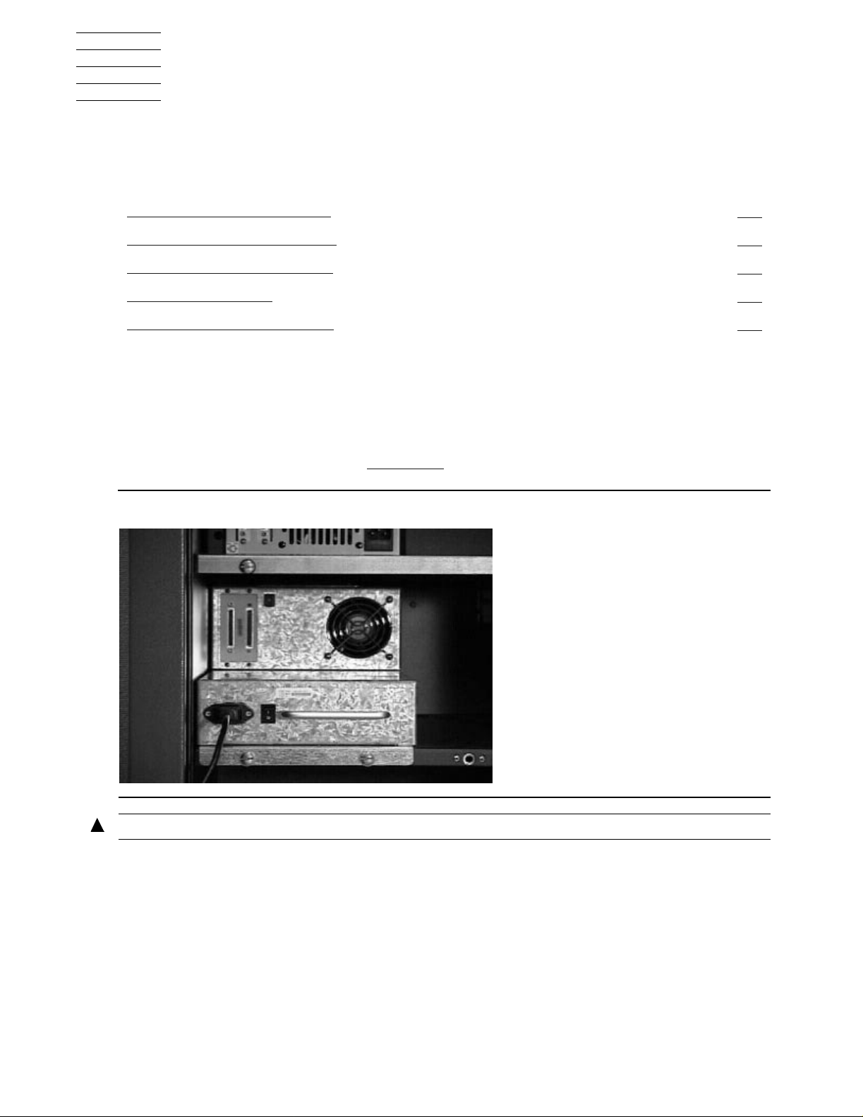
3
Installing the 5257 Tape Drive
This section includes these topics:
Topic Page
Connecting the Power Cord
Connecting the SCSI Cables
Powering on the Tape Drive
Power-On Self-Test
5257 Troubleshooting Chart
Connecting the Power Cord
1. Check that the tape drive power switch is set to 0 (OFF).
2. Connect the power cord to the tape drive power connector, and check that the
connector is fully seated. See Figure 3-1
Figure 3-1. Attaching the Power Cord
.
3-1
3-2
3-3
3-3
3-4
WARNING. Do not attach the male end of the power cord to the power outlet at this time.
5257/5257ACL Installation and User's Guide for NonStop Himalaya S-Series Tape Enclosures—522344-001
3-1
Page 32

Installing the 5257 Tape Drive
Connecting the SCSI Cables
Connecting the SCSI Cables
Note. Term Power is not supplied by the tape drive; it must be supplied by the NonStop
Himalaya S-series server Bus Adapter card.
The tape drive connects to a SCSI bus and supports only the differential alternative.
All Himalaya systems should have either the SCSI ports labeled or the international
symbols displayed to indicate the electrical configuration for that port.
Table 3-1. SCSI Cables
Part Number Description
424360-001
424361-001
424362-001
424917-001
424363-001
1 meter copper SCSI cable
3 meter copper SCSI cable
15 meter copper SCSI cable
20 meter copper SCSI cable
23 meter copper SCSI cable
Connecting the SCSI C able to the Tape Drive
1. Copy the device address to use later in the configuration process.
Caution.
connecting the cable to the drive or SCSI bulkhead.
2. Connect the SCSI cable to the left 68-pin jack at the rear of the drive as shown in
Figure 3-2. Rear View of the 5257 Tape Drive
Connector Damage:
Figure 3-2
.
Be careful not to bend or damage the pins or connectors when
3. Install the terminator at the other 68-pin jack.
5257/5257ACL Installation and User's Guide for NonStop Himalaya S-Series Tape Enclosures—522344-001
3-2
Page 33

Installing the 5257 Tape Drive
4. Repeat Steps 2 and 3 as applicable.
Connecting the SCSI Cables to the Server
Connecting the SCSI Cables to the Server
Connect the free end of the SCSI cable at the server.
WARNING. For SCSI cables, be sure that the power to the tape drive is off before
connecting to the server.
You can attach a 5257/5257ACL tape drive to a NonStop
one of the following, depending on your ty pe of server:
ServerNet/DA
•
IOMF 2 CRU
•
PMF CRU
•
Supported connections for the 5257/5257 ACL tape drives are listed in Table 3-2
Table 3-2. Connections Supported for 5257/5257ACL Tape Drives
Server ServerNet / DA IOMF CRU IOMF 2 CRU P MF CRU
S7000 YES NO NO NO
S7400 YES NO YES NO
S70000 YES NO YES NO
S72000 YES NO YES NO
S74000 YES NO YES YES
Himalaya S-series server using
PoweringontheTapeDrive
.
1. Attach the male end of the power cord to a power outlet.
2. Press the power switch on the tape drive.
3. Verify that the tape drive powers on.
Power-On Self-Test
When power is applied, the tape drive performs a POST (Power-On Self-Test). The
POST finalizes in under ten seconds. While it is running, the tape drive responds BUSY
to SCSI commands and also responds to various SCSI messages.
If the Himalaya server tries to negotiate synchronous or wide transfers, the tape system
negotiates to asynchronous or narrow. Media may require more time than the duration of
POST to become ready.
5257/5257ACL Installation and User's Guide for NonStop Himalaya S-Series Tape Enclosures—522344-001
3-3
Page 34

Installing the 5257 Tape Drive
5257 Troubleshooting Chart
5257 Troubleshooting Chart
If the 5257 drive fails during P OST or operation, use Table 3-3 to determine the problem
and the action to take.
Table 3-3. Troubleshooting Chart
If... Then... You Should...
System doe s not
recognize the tape
system.
System doe s not
recognize the tape
system.
System ma y not be configured
to r ecognize the SCSI ID.
SCSI ID may not be unique. Change the SCSI ID and
SCSI adapter parameters may
not be correct.
SCSI signal cable may be loose. Ensure SCSI cable is fully
SCSI terminator may be loose
or not present on the bus.
SCSI bus may not be terminate
correctly.
Configure your system to
recognize the tape drive’s ID.
reconfigure the system. The
new ID becomes effective at the
next powe r on or SCSI bus
reset.
Check SCSI adapter
documentation.
seated at each connector end.
Ensure correct, secure
termination of bus.
If tape system is la st or only
device on bus (except for
adapter), make sure terminator
is installed on the tape drive.
If tape drive is not the last or
only device on the bus, check
the c able connections and
ensure that the bus is properly
terminated at each end.
SCSI alter nator may not be at
end of bus or more than two
terminators may be present.
SCSI bus may be too long Limit bus length to ANSI SCSI
Too many devices on the bus. Limit the number of devices on
5257/5257ACL Installation and User's Guide for NonStop Himalaya S-Series Tape Enclosures—522344-001
3-4
Ensure that a terminator is
installed at each end of the bus.
One terminator is usually
installed at the Himalaya server
end of the bus.
standard for the SCSI inter face
being us ed.
the bus (including the SCSI
adapter) to match the limits of
the inter f ace being used.
Page 35

Installing the 5257 Tape Drive
Table 3-3. Troubleshooting Chart
If... Then... You Should...
5257 Troubleshooting Chart
The tape drive does
not power up.
Nonfatal or fatal
errors occur f or which
the c ause cannot be
determined.
A device m ay not have been
turned on, and a valid SCSI ID
may not have been configured
prior to the system powering on
and loading BIOS.
No power is reaching the tape
drive.
SCSI bus termination or the
SCSI bus cable connections
may be incorrect.
Turn drive power on first; then
turn on power to the system so
that the drive is properly
recognized by the system.
Check the tape system’s power
cable connection at the back of
the dri ve.
Ensure the SCSI bus is
truncated and that all
connections are secure.
5257/5257ACL Installation and User's Guide for NonStop Himalaya S-Series Tape Enclosures—522344-001
3-5
Page 36

Installing the 5257 Tape Drive
5257 Troubleshooting Chart
5257/5257ACL Installation and User's Guide for NonStop Himalaya S-Series Tape Enclosures—522344-001
3-6
Page 37

4
00000
00000
00000
00000
00000
00000
00000
00000
00000
00000
00000
00000
00000
00000
Operating the 5257 Tape Drive
This section includes these topics:
Topic Page
The Front Panel
Super DLTtape 1 Tape Cartridge 4-2
Loading a Cartridge 4-4
Unloading a Cartridge 4-4
Preserving Cartridges 4-5
The Front Panel
The tape drive’s front panel controls and LEDs are used to operate the 5257 tape drive
and monitor the drive’s activities. Table 4-1 describes control and LED functionality.
Figure 4-1
Figure 4-1. Tape Drive Front Panel
Tape Entry
Write-Protect
Drive Status
provides an illustration.
00000000000000000000000000000000000000000000000000000000000000000000000000000000000000000000000000000000000000000000000000000000000000000
00000000000000000000000000000000000000000000000000000000000000000000000000000000000000000000000000000000000000000000000000000000000000000
00000000000000000000000000000000000000000000000000000000000000000000000000000000000000000000000000000000000000000000000000000000000000000
00000000000000000000000000000000000000000000000000000000000000000000000000000000000000000000000000000000000000000000000000000000000000000
00000000000000000000000000000000000000000000000000000000000000000000000000000000000000000000000000000000000000000000000000000000000000000
00000000000000000000000000000000000000000000000000000000000000000000000000000000000000000000000000000000000000000000000000000000000000000
00000000000000000000000000000000000000000000000000000000000000000000000000000000000000000000000000000000000000000000000000000000000000000
LED
LED
00000000000000000000000000000000000000000000000000000000000000000000000000000000000000000000000000000000000000000000000000000000000000000
00000000000000000000000000000000000000000000000000000000000000000000000000000000000000000000000000000000000000000000000000000000000000000
00000000000000000000000000000000000000000000000000000000000000000000000000000000000000000000000000000000000000000000000000000000000000000
00000000000000000000000000000000000000000000000000000000000000000000000000000000000000000000000000000000000000000000000000000000000000000
00000000000000000000000000000000000000000000000000000000000000000000000000000000000000000000000000000000000000000000000000000000000000000
00000000000000000000000000000000000000000000000000000000000000000000000000000000000000000000000000000000000000000000000000000000000000000
00000000000000000000000000000000000000000000000000000000000000000000000000000000000000000000000000000000000000000000000000000000000000000
Reserved
Eject Button
Infrared
Communication
Port
4-1
5257/5257ACL Installation and User's Guide for NonStop Himalaya S-Series Tape Enclosures—522344-001
4-1
Page 38

Operating the 5257 Tape Drive
Super DLTtape 1 Tape Cartridge
Super DLTtape 1 Tape Cartridge
The Super DLTtape 1 tape cartridge is a half-inch cartridge containing 1,833.5 feet of
Advance Metal Particle (AMP). W ith a storage capacity of 110 GB native and up to 220
GB compressed, the cartridge has an archival life of more than 30 years and a durability
in excess of 1,000,000 head passes. See Figure 4-2
.
Figure 4-2. Super DLTtape
TM
1 Tape Cartridge
Cartridge Write-Protect Switch
The tape cartridge has a write-protect switch to prevent accidental erasure of data.
Before loading the tape cartridge into the drive, position the write-protect switch on the
front of the cartridge:
Left, so the cartridge is write-protected
•
Right, so the cartridge is write-enabled
•
When the switch is moved to the left, a small orange rectangle appears that indicates
data cannot be written to the tape. The arrow (beneath the orange rectangle and over the
two lines on the write-protect switch) indicates that data cannot be written to the tape.
On the right side of the write-protect switch, an arrow over one line indicates that if the
operator slides the write-protect switch to the right, data can be written to the tape. See
Figure 4-3
5257/5257ACL Installation and User's Guide for NonStop Himalaya S-Series Tape Enclosures—522344-001
.
4-2
Page 39

Operating the 5257 Tape Drive
Figure 4-3. Tape Cartridge
Cartridge Wr ite-Protec t Switch
Orange Indicator
Write Protect Switch
Data Protection
Move the cartridge write-protect switch to the left to activate (light) the write-protect
LED. If the drive is writing to the tape, write protect does not take effect until the
current write operation completes.
Table 4-1
moved before loading the cartridge.
Table 4-1. Before Loading the Cartridge
If the write-protect switch is
moved… Then…
To the left, the tape is write-protected;
the orange indicator on the cartridge
appears.
To the right, the tape is write-enabled. Data can be written to the tape (if it is
Table 4-2
moved during operation.
describes what happens to data protection when the write-protect switch is
Data cannot be written to the tape.
not software write-protected).
describes what happens to data protection when the write-protect switch is
Table 4-2. After Loading the Cartridge and Operating
If the write-protect switch is
moved… Then…
From the write-protected position to
write-enabled
From write-enabled to write-protected The tapebecom es write-protected (aft er
5257/5257ACL Installation and User's Guide for NonStop Himalaya S-Series Tape Enclosures—522344-001
The tape becomes write-enabled (after
a va riable amount of seconds).
a va riable amount of seconds).
4-3
Page 40

Operating the 5257 Tape Drive
Loading a Cartridge
Loading a Cartridge
1. Insert the cartridge into the receiver on the front of the tape drive. See Figure 4-4.
2. Push the cartridge completely into the drive receiver. The Drive Status LED blinks
to show that the tape is loading. When the tape reaches the BOT marker, the LED
light stops blinking, and the tape is ready for use.
Figure 4-4. Loading a Tape Cartridge
Unloading a Cartridge
Caution. Remove a cartridge from the drive before turning off the NonStop Himalaya system
power. Failure to remove a cartridge can result in cartridge and drive damage. When the
cartridge is removed from the drive, return the cartridge to its plastic case to prolong cartridge
life.
1. Press the Eject button on the front panel, and the drive completes any active writing
of data to the tape. The Drive Status LED blinks as the tape rewinds. When the tape
is finished rewinding, the drive ejects the cartridge and the Drive Status LED light
stops blinking.
2. Remove the cartridge from the drive and return it to its plastic case. See Figure 4-5
5257/5257ACL Installation and User's Guide for NonStop Himalaya S-Series Tape Enclosures—522344-001
4-4
.
Page 41

Operating the 5257 Tape Drive
Figure 4-5. Unloading a Tape Cartridge
Preserving Cartridges
Pre ser ving Cartridges
For longer life of recorded or unrecorded cartridges, store cartridges in a clean
environment with these conditions:
Protect cartridges from shock, vibration, moisture and magnetic fields.
•
Do not drop or bang the cartridge. This can displace the tape leader, making the
•
cartridge unusable and may damage the drive.
If you drop a cartridge, perform a visual media inspection before inserting it into the
•
drive.
Store cartridge vertically when not in use.
•
Store the data cartridge in the plastic enclosure it was shipped in.
•
Never touch the tape or tape leader. Dust and oils from your skill will contaminate
•
the tape and affect performance.
Keep tape cartridges out of direct sunlight and away from heaters.
•
Store tape cartridge in temperatures between 10°C and 40°C (50°F to 104°F). For
•
longer cartridge life, always store the cartridge in its plastic container and in room
environment conditions of 72°F± 7°F (22°± 4°C).
5257/5257ACL Installation and User's Guide for NonStop Himalaya S-Series Tape Enclosures—522344-001
4-5
Page 42

Operating the 5257 Tape Drive
If the tape cartridge has been exposed to heat or cold extremes, stabilize the
•
cartridge at room temperature for the same amount of time it was exposed (up to 24
hours).
Do not place cartridges near electromagnetic interference sources, such as terminals,
•
motors, and video or x-ray equipment to protect data.
Store tape cartridges in a dust-free environment where the relative humidity is
•
between 20 percent and 80 percent. For longer cartridge life, store the cartridge at 40
percent ± 20 percent relative humidity.
Use the sliding labels provided. Do not use adhesive labels, and do not write on the
•
cartridge.
Place an labels only in the slide-in slot on the front of the cartridge.
•
Preserving Cartridges
5257/5257ACL Installation and User's Guide for NonStop Himalaya S-Series Tape Enclosures—522344-001
4-6
Page 43

5
Installing and Configuring the
5257ACL Tape Drive
This section includes these topics:
Topic Page
Connecting the Power Cord
Installing the SCSI Cables 5-1
Powering on the Tape Drive 5-3
Configuring the 5257ACL Tape Drive 5-3
Setting Up Reserved Slots 5-5
Descriptions of Configuration Options 5-6
Connecting the Power Cord
1. Check that the power is off (the LCD screen is blank and no lights are illuminated).
2. Connect the power cord to the 5257ACL power receptacle, and check that it is fully
seated.
3. Connect the other end of the power cord to a nearby AC outlet.
Caution. The 5257ACL drive does not have protection against lightning surges. For this
reason, those customers located in high-risk areas should use external surge protection rated
for use in their location and be able to handle the power demand of the tape drive cabinet.
5-1
Installing the SCSI Cables
Note. Term Power is not supplied by the tape drive; it must be supplied by the Host Bus
Adapter card.
The tape drive connects to a SCSI bus and supports only the differential alternative.
All NonStop Himalaya systems should have either the SCSI ports labeled or the
international symbols displayed to indicate the electrical configuration for that port.
Part Number Description
424360-001 1 meter copper SCSI cable
424361-001 3 meter copper SCSI cable
424362-001 15 meter copper SCSI cable
424917-001 20 meter copper SCSI cable
424363-001 23 meter copper SCSI cable
5257/5257ACL Installation and User's Guide for NonStop Himalaya S-Series Tape Enclosures—522344-001
5-1
Page 44

Installing and Configuring the 5257ACL Tape Drive
00000
00000
00000
00000
00000
00000
00000
00000
00000
00000
00000
00000
00000
00000
00000
Connecting the SCSI Cable to the Tape Drive
Connecting the SCSI C able to the Tape Drive
1. Copy the device address to use later in the configuration process.
Caution.
connecting the cable to the drive or SCSI bulkhead.
Connector Damage:
Be careful not to bend or damage the pins or connectors when
2. Connect the SCSI cable to the right 68-pin jack at the rear of the drive as shown in
Figure 5-1
.
Figure 5-1. Rear View of the 5257ACL Tape Drive
00000000000000000000000000000000000000000000000000000000000000000000000000000000000000000000000000000000000000000000000000000000000000000000000000000000000000000000000000000000000000000000000000000000000000000000
00000000000000000000000000000000000000000000000000000000000000000000000000000000000000000000000000000000000000000000000000000000000000000000000000000000000000000000000000000000000000000000000000000000000000000000
00000000000000000000000000000000000000000000000000000000000000000000000000000000000000000000000000000000000000000000000000000000000000000000000000000000000000000000000000000000000000000000000000000000000000000000
00000000000000000000000000000000000000000000000000000000000000000000000000000000000000000000000000000000000000000000000000000000000000000000000000000000000000000000000000000000000000000000000000000000000000000000
00000000000000000000000000000000000000000000000000000000000000000000000000000000000000000000000000000000000000000000000000000000000000000000000000000000000000000000000000000000000000000000000000000000000000000000
00000000000000000000000000000000000000000000000000000000000000000000000000000000000000000000000000000000000000000000000000000000000000000000000000000000000000000000000000000000000000000000000000000000000000000000
00000000000000000000000000000000000000000000000000000000000000000000000000000000000000000000000000000000000000000000000000000000000000000000000000000000000000000000000000000000000000000000000000000000000000000000
00000000000000000000000000000000000000000000000000000000000000000000000000000000000000000000000000000000000000000000000000000000000000000000000000000000000000000000000000000000000000000000000000000000000000000000
00000000000000000000000000000000000000000000000000000000000000000000000000000000000000000000000000000000000000000000000000000000000000000000000000000000000000000000000000000000000000000000000000000000000000000000
00000000000000000000000000000000000000000000000000000000000000000000000000000000000000000000000000000000000000000000000000000000000000000000000000000000000000000000000000000000000000000000000000000000000000000000
00000000000000000000000000000000000000000000000000000000000000000000000000000000000000000000000000000000000000000000000000000000000000000000000000000000000000000000000000000000000000000000000000000000000000000000
00000000000000000000000000000000000000000000000000000000000000000000000000000000000000000000000000000000000000000000000000000000000000000000000000000000000000000000000000000000000000000000000000000000000000000000
00000000000000000000000000000000000000000000000000000000000000000000000000000000000000000000000000000000000000000000000000000000000000000000000000000000000000000000000000000000000000000000000000000000000000000000
00000000000000000000000000000000000000000000000000000000000000000000000000000000000000000000000000000000000000000000000000000000000000000000000000000000000000000000000000000000000000000000000000000000000000000000
00000000000000000000000000000000000000000000000000000000000000000000000000000000000000000000000000000000000000000000000000000000000000000000000000000000000000000000000000000000000000000000000000000000000000000000
3. Install the terminator at the other (left) 68-pin jack.
4. Repeat Steps 2 and 3 as applicable.
Connecting the SCSI Cable to the Server
Caution. Install the free end of the interface cable to NonStop Himalaya server. For
SCSI cables, be sure that the power to the tape drive is off before connecting to the
server.
You can attach a 5257/5257ACL tape drive to a NonStop Himalaya S-series server using
one of the following, depending on your type of server:
ServerNet/DA
•
IOMF 2 CRU
•
PMF CRU
•
Supported connections for the 5257/5257 ACL tape drives are listed in Table 5-1
5257/5257ACL Installation and User's Guide for NonStop Himalaya S-Series Tape Enclosures—522344-001
5-2
.
Page 45

Installing and Configuring the 5257ACL Tape Drive
00000
00000
00000
00000
00000
Table 5-1. Connections Supported for 5257/5257ACL Tape Drives
Server ServerNet / DA IOMF CRU IOMF 2 CRU P MF CRU
S7000 YES NO NO NO
S7400 YES NO YES NO
S70000 YES NO YES NO
S72000 YES NO YES NO
S74000 YES NO YES YES
PoweringontheTapeDrive
1. Attach the male end of the power cord to a power outlet.
2. Press the power switch on the tape drive.
3. Verify that the tape drive powers on.
Powering on the Tape Drive
Configuring the 5257ACL Tape Drive
For information on the different menu's and submenu's featured on the 5257ACL T ape
drive, see Section 6, “Operating the 5257ACL Tape Drive.”
The 5257ACL library controller is factory set to SCSI ID 3; the 5257ACL drive is
factory set to SCSI ID 5, unless otherwise specified. The drive is factory set for parity
generation, and checking is enabled.
Setting the SCSI ID
1. Turn the 5257ACL on. Wait until the power-on self-test terminates and the default
screen appears. Figure 5-2 shows the default screen for the unit, which indicates a
tape magazine with only one cartridge in slot 1. Rectangles will apper on line three
on the default screen in positions that correspond to the slots where cartridges are
present.
Figure 5-2. Default Screen
000000000000000000000000000000000000000000000000000000000000000000000000
000000000000000000000000000000000000000000000000000000000000000000000000
000000000000000000000000000000000000000000000000000000000000000000000000
000000000000000000000000000000000000000000000000000000000000000000000000
000000000000000000000000000000000000000000000000000000000000000000000000
2. At the Default Screen, press Enter . The Main Menu in Figure 5-3
5257/5257ACL Installation and User's Guide for NonStop Himalaya S-Series Tape Enclosures—522344-001
5-3
appears.
Page 46

Installing and Configuring the 5257ACL Tape Drive
00000
00000
00000
00000
0000
0000
0000
0000
00000
00000
00000
00000
Setting the SCSI ID
Figure 5-3. Main Menu
0000000000000000000000000000000000000000000000000000000000000000000000000000
0000000000000000000000000000000000000000000000000000000000000000000000000000
0000000000000000000000000000000000000000000000000000000000000000000000000000
0000000000000000000000000000000000000000000000000000000000000000000000000000
3. Press the downbutton four times to move the cursorto Configure Menu, then
press Enter. The Configure submenu in Figure 5-4 appears. Note that the
end of the fourth line means additional configuration options can be reached by
scrolling.
Figure 5-4. Configure Submenu
000000000000000000000000000000000000000000000000000000000000000000000000000000000000000000000000000000000000000000000000000000000000000000000000000000000000000000000000000000000000000000000000000
000000000000000000000000000000000000000000000000000000000000000000000000000000000000000000000000000000000000000000000000000000000000000000000000000000000000000000000000000000000000000000000000000
000000000000000000000000000000000000000000000000000000000000000000000000000000000000000000000000000000000000000000000000000000000000000000000000000000000000000000000000000000000000000000000000000
000000000000000000000000000000000000000000000000000000000000000000000000000000000000000000000000000000000000000000000000000000000000000000000000000000000000000000000000000000000000000000000000000
at the
4. To select a configuration option, press the up
control panel to move the cursor
on the display to the option to change. In this
or downscroll buttons on the
case, select "Set SCSI." Press Enter to display the choices for that option. The
submenu in Figure 5-5
appears.
Figure 5-5. Set SCSI Submenu
0000000000000000000000000000000000000000000000000000000000000000000000000000000000000000000000000000000000000000
0000000000000000000000000000000000000000000000000000000000000000000000000000000000000000000000000000000000000000
0000000000000000000000000000000000000000000000000000000000000000000000000000000000000000000000000000000000000000
0000000000000000000000000000000000000000000000000000000000000000000000000000000000000000000000000000000000000000
Note. Look c losely at the submenu in Figu re 5-5. Note th at th e c urs or4 on the dis play is next
to line 1, and th at line 2 is indente d, indicating th at t his is a two-tiered me nu. Th e s c roll buttons
work on two levels in this t y pe of menu, which is typical of m any su bm enus under C onfigure
Menu. Firs t - level navigation: when you pres s t he
Pressing th e button again, you w ill s c roll down to DLT Bus ID. If you press the button, th e
moves back to line 1.
If you press Enter while the
second level. As a result, themoves next to line 2 (or line 4), and aappears at the end of
line 4, indicating that there is a list of options that you can view by scrolling.
is next to line 1 (or line 3), the scroll buttons operate on the
button is pres s ed, t he moves to line 3.
5. Note that the Library SCSI ID is set to 3. If the DLT1 bus ID needs to be set to 5,
check that the cursor
is next to line 1, and press thebutton repeatedly until the
display scrolls, as shown in Figure 5-6.
5257/5257ACL Installation and User's Guide for NonStop Himalaya S-Series Tape Enclosures—522344-001
5-4
Page 47

Installing and Configuring the 5257ACL Tape Drive
0000
0000
0000
0000
0000
0000
0000
0000
Setting Up Reserved Slots
Figure 5-6. SCSI Submenu Scrolled
000000000000000000000000000000000000000000000000000000000000000000000000000000000000000000000000000000000000000000000000000000000000000000000000000000000000000000000000000000000000000000000000000
000000000000000000000000000000000000000000000000000000000000000000000000000000000000000000000000000000000000000000000000000000000000000000000000000000000000000000000000000000000000000000000000000
000000000000000000000000000000000000000000000000000000000000000000000000000000000000000000000000000000000000000000000000000000000000000000000000000000000000000000000000000000000000000000000000000
000000000000000000000000000000000000000000000000000000000000000000000000000000000000000000000000000000000000000000000000000000000000000000000000000000000000000000000000000000000000000000000000000
6. With thenext to line 3, press Enter. Themoves to line 4, theappears at the
end of line 1, and theappears at the end of line 4. On line 4, scroll to display more
options. Scroll so that line 5 is displayed, then press Enter to save the new selection.
An * appears at the left of line 5 to indicate that it is the current selection.
7. Press Escape repeatedly until the submenu in Figure 5-4
reappears.
8. Repeat steps 1 through 7 for each configuration option that needs to be change.
Setting Up Reserved Slots
One of the reserved slots can be used for a cleaning cartridge to use the Autoclean
function; however, this function can be used only while operating in Random Library
Mode in conjunction with NonStop Himalaya software, such as TSI's Auto Cartridge
Loader Media Manager (ACLMM).
1. Navigate from the Default screen through the Main menu to the Configure submenu
as shown in Figure 5-2
2. Scroll down the Configure submenu to “Set Reserved Slots” and select. The screen
shown in Figure 5-7
Figure 5-7. Set Reserved Slots Submenu
000000000000000000000000000000000000000000000000000000000000000000000000000000000000000000000000000000000000000000000000000000000000000000000000000000000000000000000000000000000000000000000000000
000000000000000000000000000000000000000000000000000000000000000000000000000000000000000000000000000000000000000000000000000000000000000000000000000000000000000000000000000000000000000000000000000
000000000000000000000000000000000000000000000000000000000000000000000000000000000000000000000000000000000000000000000000000000000000000000000000000000000000000000000000000000000000000000000000000
000000000000000000000000000000000000000000000000000000000000000000000000000000000000000000000000000000000000000000000000000000000000000000000000000000000000000000000000000000000000000000000000000
through Figure 5-4.
appears.
3. With the
next to line 1, press Enter. Themoves to line 2, anappears at the
end of line 4, and anappears at the end of line 1. On line 2, scroll to specify the
number of slots ot be reserved. Scroll to the desired number, and press Enter.
4. Press Escape repeatedly to return to the Default Screen.
5257/5257ACL Installation and User's Guide for NonStop Himalaya S-Series Tape Enclosures—522344-001
5-5
Page 48

Installing and Configuring the 5257ACL Tape Drive
Descriptions of Configuration Options
Descriptions of Configurat io n Options
The items available on the Configuration menu are described next.
SetDataFormat
Use this setting to set the data format and enable or disable data compression. The data
format options are: Auto Selection, THZ01, THZ02, DLT2000, DLT2000XT , DL T4000,
or DLT7000. Compression cannot be enabled when either the THZ01 or THZ02 format
is used. This setting applies to the next or the currently loaded cartridge only . An unload
command returns to the default. This setting does not display the format of the loaded
tape; use the Show Status menu for this purpose. Default is Auto Selection for both
density and compression.
Set SCSI
Use this setting to enable or disable the robotics SCSI bus parity checking and set the
SCSI addresses of the drives and the robotics. The defaults are: parity on; DLT 1 Bus ID
= 5; Library Bus ID = 3.
Set Library Mode
Use this setting to set the robotics operating mode to Random or Sequential DL T1.
Random mode provides complete NonStop Himalaya control of the robotics; sequential
modes are locally controlled. Sequential DLT1 begins with any cartridge loaded into
DLT1. The 5257ACL monitors the status of DLT1, and when the cartridge is unloaded
by the NonStop Himalaya, it loads the next cartridge in magazine numerical order. This
operation continues to cycle until all of the cartridges have been loaded, or until an
empty slot is encountered. The default is Sequential.
When Sequential DLT1 is selected, an additional Sequential mode option appears that
lets you select Normal or Recirculate options. Normal option operates as described
above. In Recirculate mode, instead of stopping after the NonStop Himalaya has
unloaded the cartridge in the last slot, the operation continues by loading the cartridge in
Slot 1. Recirculation continues until an empty slot is encountered. The default for
Sequential mode is Normal.
Set Element Base
Use this setting to set the base addresses of each of the three SCSI Elements of the
module. To identify sources and destinations in SCSI commands to the robotics, the
5257ACL is divided into elements, each of which is assigned a separate designator or
Element Address. The Transport Element is the robotics mechanism itself; the
S torage Elements are the ten slots in the magazine; the Transfer Element is the drive.
The 5257ACL reports these settings in response to the SCSI Mode Sense command in
the Element Address Assignment Page. The defaults are Transport = 0000; Storage
element base = 0001; T ransfer element base = 00F0 (DLT 1).
5257/5257ACL Installation and User's Guide for NonStop Himalaya S-Series Tape Enclosures—522344-001
5-6
Page 49

Installing and Configuring the 5257ACL Tape Drive
Set Identification
Set Identification
Use this setting to specify the response of the 5257ACL's robotics to the SCSI Inquiry
command in the Vendor ID and the Product ID fields. The defaults are: Vendor ID =
TSI; Product ID = 525X.
Set Date
Use this setting to set the module's calendar.
Set Time
Use this setting to set the module's clock.
Set Baud Rate
Use this setting to set the data transmission rate of the module's trace port. This function
is intended for use by CE's only. The default is 38400 bits/sec.
Set Serial number
Use this setting to alter the 5257ACL's serial number stored in the unit. The 5257ACL's
robotics reports these settings in response to the SCSI Inquiry command in the Unit
Serial Number page.
Set Unloa d Mode
Use this setting to determine whether a SCSI Move Medium command is interpreted as
Implicit or Explicit. If Implicit, the module unloads a drive before attempting to move a
cartridge from that drive. If Explicit, the NonStop Himalaya must issue a SCSI Unload
command to a drive before each Move Medium command that removes a cartridge from
that drive. The default is Implicit.
Set Aut oclean Mode
Use this setting to enable an automatic cleaning cycle that operates as part of the
cartridge unload sequence whenever the Use Cleaner LED comes on. This function can
be used only in Random Operating Mode. To use this option, reserve a slot for a
cleaning cartridge by using the Reserve Slots option. The default is disabled.
Set Negotiation
This option offers two choices: Initiate Synchronous Negotiation and Set Transfer Rate.
Set Initiate Negotiate to allow the 5257ACL to initiate SCSI Synchronous Negotiation
with the NonStop Himalaya (the default is No). The 5257ACL always responds to
Himalaya-initiated negotiation.
Set Transfer Rate can be set to 10 MB/sec, 5 MB/sec or asynchronous. The default is 10
MB/sec.
5257/5257ACL Installation and User's Guide for NonStop Himalaya S-Series Tape Enclosures—522344-001
5-7
Page 50

Installing and Configuring the 5257ACL Tape Drive
Set Reserved Sl o ts
Set Reserved Slots
Use this setting to make specified number of the slots in the magazine inactive. This
function can be used only in Random Operating Mode. At least one reserved slot is
required to use the Autoclean option.
Set Special Configurations
Use this option to choose between two lengths of the Mode Sense/Select Device
Capabilities Page (SCSI Page 1fH), which are 14 bytes and 18 bytes, to accommodate
different SCSI device implementations of their page.
Set Default
This option resets all of the preceding configuration options to their factory defaults.
Under no circumstances should this option be used.
T able 5-2
summarizes the configuration and default settings for the ACL. Other possible
settings are shown in the second column.
Table 5-2. 5257ACL Configuration Options (page 1 of 2)
Option Settings Default
Data Format Density: Auto Selection Auto
Compression: Enable, Disable (Enable at 10.0
only)
SCSI Lib Bus Parity : Enable, Disable
Lib Bus ID:(SCSIID)
SDLT1 Bus ID: (SCSI ID)
Library Mode Random, Seq. SDLT1
Sequential Mode: Normal, Recirculate
Element Base Transport: NNNN (hex)
Storage: NNNN (hex)
Transfer: NNNN (hex)
Identification Vendor ID: OVERLAND
Auto
Enabled
3
5
Sequential
Normal
0000
0001
00F0
TSI
Product ID:LXB
Date DD,MMM,YYYY Current Date
Time HH,MM Current Time
Baud Rate [TSI CE Use Only] 38400
Serial Number NXNNNNNNN 999999999
Unload Mode Implicit, Explicit Implicit
AutoClean Mode Disabled, Enabled Disabled
5257/5257ACL Installation and User's Guide for NonStop Himalaya S-Series Tape Enclosures—522344-001
5-8
525X ACL
Page 51

Installing and Configuring the 5257ACL Tape Drive
Table 5-2. 5257ACL Configuration Options (page 2 of 2)
Option Settings Default
Negotiation Negotiation Mode: Do Not Initiate, Initiate Do Not Initiate
Set Default
Transfer Rate: 10 MB/sec, 5 MB/sec,
10 MB/sec
asynchronous
Reserved Slots Reserved Slots: 0 through n 0
Special Config Mode Page 1F Length: Short (0x0E), Long
Short
(0x12)
Model Number:
OVERLAND LX, Blank Line, DIGITAL TL89x,
TSI 525X
ACL
Vendor Unique
TUR Reporting: Standard: report Not Ready;
Standard
Custom: report Good in Sequential Mode
Init. Elem. Status: No Inventory, Force
No Inventory
Inventory, Force Label Scan
Unit Attn. Report: One, All All
Element Base: One Based, Zero Based One Based
LabelSize: 1 through 8 characters 8 Chars
Label Alignment: Left Align, Right Align Left
Abort Move Status: Busy, Not Ready Busy
Default ODI Defaults, Compaq Defaults (not to be used) ODI Defaults
5257/5257ACL Installation and User's Guide for NonStop Himalaya S-Series Tape Enclosures—522344-001
5-9
Page 52

Installing and Configuring the 5257ACL Tape Drive
Set Default
5257/5257ACL Installation and User's Guide for NonStop Himalaya S-Series Tape Enclosures—522344-001
5-10
Page 53

6
Operating the 5257ACL Tape
Enclosure
This section includes these topics:
Topic Page
Front Panel
Media Locks 6-5
The Main Menu 6-7
Unlocking the Control Panel 6-15
Displaying Firmware Revision 6-15
Displaying Error Logs 6-16
Inserting and Removing Cartridges 6-17
Removing the Magazine 6-17
Emergency Magazine Removal 6-18
Inserting a Magazine Into the 5257ACL 6-18
Inserting Cartridges Into the Magazine 6-18
Tape Requirements 6-19
Cartridge Handling and Storage 6-19
Write Protection 6-20
Front Panel
6-1
The front panel includes the power switch, the magazine door, and the control panel,
which has indicators, buttons, and a display.
Power Switch
The power switch controls the supply of AC power to the 5257ACL. It is a pushon/push-off switch. When the power is on, the backplane of the control panel display is
illuminated.
Magazine Door
The magazine door is the entry way for the 10-slot magazine, which holds 10 cartridges.
5257/5257ACL Installation and User's Guide for NonStop Himalaya S-Series Tape Enclosures—522344-001
6-1
Page 54

Operating the 5257ACL Tape Enclosure
Control Panel
Indicators
The control panel consists of four LED indicators, a 4-line by 20 character backlit LCD
display, and four buttons.
The four LED indicators on the control panel are:
The Ready indicator (green) is illuminated when the 5257ACL is ready to accept
•
commands from either the Control Panel or the NonStop Himalaya computer. When
the Menu Mode is entered, the Ready indicator goes out.
The Use Cleaner LED (yellow) indicates that the drive requires cleaning. Insert the
•
cleaning cartridge shipped with the system and let it run. When done, the cartridge
ejects itself automatically.
When either the Drive Fault or the Loader Fault LED (red) is illuminated, a Fault
•
Screen appears on the LCD display. The Fault Screen is described later in this
section.
Control Panel
Buttons
The four buttons on the control panel are labeled Escape, Enter,, and. These
buttons do not directly control specific functions or options. Instead, use the scroll
buttons to navigate from the Default Screen through a multilevel menu structure, then
select the desired option from the appropriate menu by pressing Enter.
Important usage tips are:
To enter the Menu mode and display the Main menu from the Default screen, press
•
Enter.
To return to the Main menu from a submenu, press Escape repeatedly until the Main
•
menu appears. Pressing the Escape button while the Main menu is displayed exits
the Menu mode and returns you to the Default screen.
To display the Show Status menu only without entering the Menu mode, press
•
Escape at the Default screen. The system remains online.
Note. When the Menu mode is entered, the Ready light goes out. This means that the module
is offline, and the system responds to a ll commands from the Himalaya with a SCSI Not Ready
message until the Menu mode is exited, and the Ready light goes on.
Display
The display on the control panel is capable of displaying four lines of 20 characters
each, to allow the use of easy-to-understand messages.
5257/5257ACL Installation and User's Guide for NonStop Himalaya S-Series Tape Enclosures—522344-001
6-2
Page 55

Operating the 5257ACL Tape Enclosure
0000
0000
0000
Table 6-1. Control Panel Functions
Control Panel
Screen Escape Enter
POST N.A. N.A. N.A. N.A.
Default Displays Show Status
menu
Status Menu
(while online)
In Menu
Mode
Fault N.A. Clears Soft
Returns to Default
screen
Does one of:
Rejects currently
•
displayed choice
Aborts Control
•
Panel operation
in progress
Exits to next
•
higher menu level
Exits Menu mode
•
to Default screen
Enters
Menu mode
Same as in
Menu mode
Accepts
currently
displayed
choice
Errors
N.A. N.A.
Same as in
Menu mode
Does one of:
Scrolls one
•
line up
through list
of options
Scrolls part
•
of display
one line to
top of list of
options
N.A. N.A.
Same as in
Menu mode
Does one of:
•
•
Scrolls one
line down
through list
of options
Scrolls part
of display
one line to
bottom of
list of
options
Note. There is an auto-repeat feature for the scroll buttons. When you press either scroll
button for more than one-half second, the control panel behaves as if you were pressing and
releasing the button four times per second. This effect stops when you release the button.
Display M essage s
The control panel display can show messages of up to four lines of 20 characters each.
Many of these messages and their functions are described next. Those displays that are
described in other sections are cross-referenced here.
Power-On Self-Test Screen
When power is first applied to the module, a series of power-on self-test (POST)
diagnostics are performed. During POST execution, the model number of the module,
the current date and time, the firmware revision, and the status or result of the test in
progress are displayed on the control panel, as shown in Figure 6-3.
Figure 6-1. POST Screen
000000000000000000000000000000000000000000000000000000000000000000000000000000000000000000000000000000000000000000000000000000000000000000000000000000000000000000000000000000000000000000000000000
000000000000000000000000000000000000000000000000000000000000000000000000000000000000000000000000000000000000000000000000000000000000000000000000000000000000000000000000000000000000000000000000000
000000000000000000000000000000000000000000000000000000000000000000000000000000000000000000000000000000000000000000000000000000000000000000000000000000000000000000000000000000000000000000000000000
5257/5257ACL Installation and User's Guide for NonStop Himalaya S-Series Tape Enclosures—522344-001
6-3
Page 56

Operating the 5257ACL Tape Enclosure
0000
0000
0000
0000
0000
0000
Initialization Screens
After the POST is completed, the library rob otics system begins initialization and a
series of screens similar to Figure 6-4 appear.
Figure 6-2. Initialization Screen
000000000000000000000000000000000000000000000000000000000000000000000000000000000000000000000000000000000000000000000000000000000000000000000000000000000000000000000000000000000000000000000000000
000000000000000000000000000000000000000000000000000000000000000000000000000000000000000000000000000000000000000000000000000000000000000000000000000000000000000000000000000000000000000000000000000
000000000000000000000000000000000000000000000000000000000000000000000000000000000000000000000000000000000000000000000000000000000000000000000000000000000000000000000000000000000000000000000000000
000000000000000000000000000000000000000000000000000000000000000000000000000000000000000000000000000000000000000000000000000000000000000000000000000000000000000000000000000000000000000000000000000
Default Screen
After the POST diagnostics have concluded successfully, and initialization is complete,
the default screen shown in Figure 6-5 appears.
Figure 6-3. Default Screen
Control Panel
000000000000000000000000000000000000000000000000000000000000000000000000000000000000000000000000000000000000000000000000000000000000000000000000000000000000000000000000000000000000000000000000000
000000000000000000000000000000000000000000000000000000000000000000000000000000000000000000000000000000000000000000000000000000000000000000000000000000000000000000000000000000000000000000000000000
The first line of the Default Screen shows the status of th e DLT drive within the
5257ACL. Possible status conditions are:
No Tape
•
Idle
•
Rewinding
•
Seeking
•
Reading
•
Writing
•
Erasing
•
Cleaning
•
Unloaded
•
Loading
•
Unloading
•
Calibrating
•
The screen’s second line displays possible status conditions of the library robotics:
Loader Idle
•
5257/5257ACL Installation and User's Guide for NonStop Himalaya S-Series Tape Enclosures—522344-001
6-4
Page 57

Operating the 5257ACL Tape Enclosure
0000
0000
0000
0000
Fetch
•
Stow
•
Diag Active
•
Diag Complete
•
Taking Inventory
•
Elevator Home
•
Checking Drive(s)
•
Orphaned Cartridge
•
Trapped Cartridge
•
Scanning Labels.
•
The third line in Figure 6-5 represents a map of the tape magazine. A 10-slot magazine
is shown. The number 1 shows the location of Slot 1 (the front slot) in the map. The
number 10 shows the location of Slot 10 (the rear slot) in the map. A rectangle on this
line indicates that a cartridge is present in the corresponding slot of the magazine. An
underline means that no cartridge is present.
Media Locks
Fault Screen
When a fault is detected, a screen similar to Figure 6-6 appears. At the same time, either
the Drive Fault or the Loader Fault LED is illuminated.
Figure 6-4. Fault Screen
000000000000000000000000000000000000000000000000000000000000000000000000000000000000000000000000000000000000000000000000000000000000000000000000000000000000000000000000000000000000000000000000000
000000000000000000000000000000000000000000000000000000000000000000000000000000000000000000000000000000000000000000000000000000000000000000000000000000000000000000000000000000000000000000000000000
000000000000000000000000000000000000000000000000000000000000000000000000000000000000000000000000000000000000000000000000000000000000000000000000000000000000000000000000000000000000000000000000000
000000000000000000000000000000000000000000000000000000000000000000000000000000000000000000000000000000000000000000000000000000000000000000000000000000000000000000000000000000000000000000000000000
The first line in Figure 6-6 shows a numerical fault symptom code (FSC). The second
line shows a brief description of the error, in place of the Error Description message.
The third and fourth lines contain a one-line or two-line message describing the initial
error recovery procedure (ERP).
Selecting Control Panel Display Modes
As previously described, the POST screens, the Initialization screen and the Default
screen appear without operator or Himalaya intervention. The Fault screens appear
whenever a fault occurs. The screens that follow appear in response to operator actions.
Media Locks
To avoid accidental interruption of module operation while the Himalaya is accessing
the module, the control panel can be electronically locked by using the Security menu
5257/5257ACL Installation and User's Guide for NonStop Himalaya S-Series Tape Enclosures—522344-001
6-5
Page 58

Operating the 5257ACL Tape Enclosure
described later in this section. After the contr ol panel is locked, you must use an unlock
code to enter the Menu mode. The control panel lock prevents access to the Unlock
Door item on the Main menu; therefore, it locks the med ia as well. See the information
on the Security menu under "Navigating the Main Menu" on page XXXXXXXXXXXX.
The media can be locked by software running on the NonStop Himalaya system, using
the SCSI Allow/Prevent Medium Removal command. The 5257ACL provides no
control panel override for this command. Exiting the Himalaya system, you can restore
media access by cycling 5257ACL power.
Media Locks
5257/5257ACL Installation and User's Guide for NonStop Himalaya S-Series Tape Enclosures—522344-001
6-6
Page 59

Operating the 5257ACL Tape Enclosure
00000
00000
00000
00000
00000
00000
00000
00000
00000
00000
00000
00000
00000
00000
00000
00000
00000
00000
00000
00000
00000
00000
00000
00000
00000
00000
00000
00000
00000
00000
00000
00000
00000
00000
00000
00000
00000
00000
00000
00000
The Main Menu
The Main Menu
Figure 6-5. 5257ACL Menu S tructur e
00000000000000000000000000000000000000000000000000000000000000000000000000000000000000000000000000000000000000000000000000000000000000000000000000000000000000000000000000000000000000000000000000000000000
00000000000000000000000000000000000000000000000000000000000000000000000000000000000000000000000000000000000000000000000000000000000000000000000000000000000000000000000000000000000000000000000000000000000
00000000000000000000000000000000000000000000000000000000000000000000000000000000000000000000000000000000000000000000000000000000000000000000000000000000000000000000000000000000000000000000000000000000000
00000000000000000000000000000000000000000000000000000000000000000000000000000000000000000000000000000000000000000000000000000000000000000000000000000000000000000000000000000000000000000000000000000000000
00000000000000000000000000000000000000000000000000000000000000000000000000000000000000000000000000000000000000000000000000000000000000000000000000000000000000000000000000000000000000000000000000000000000
00000000000000000000000000000000000000000000000000000000000000000000000000000000000000000000000000000000000000000000000000000000000000000000000000000000000000000000000000000000000000000000000000000000000
00000000000000000000000000000000000000000000000000000000000000000000000000000000000000000000000000000000000000000000000000000000000000000000000000000000000000000000000000000000000000000000000000000000000
00000000000000000000000000000000000000000000000000000000000000000000000000000000000000000000000000000000000000000000000000000000000000000000000000000000000000000000000000000000000000000000000000000000000
00000000000000000000000000000000000000000000000000000000000000000000000000000000000000000000000000000000000000000000000000000000000000000000000000000000000000000000000000000000000000000000000000000000000
00000000000000000000000000000000000000000000000000000000000000000000000000000000000000000000000000000000000000000000000000000000000000000000000000000000000000000000000000000000000000000000000000000000000
00000000000000000000000000000000000000000000000000000000000000000000000000000000000000000000000000000000000000000000000000000000000000000000000000000000000000000000000000000000000000000000000000000000000
00000000000000000000000000000000000000000000000000000000000000000000000000000000000000000000000000000000000000000000000000000000000000000000000000000000000000000000000000000000000000000000000000000000000
00000000000000000000000000000000000000000000000000000000000000000000000000000000000000000000000000000000000000000000000000000000000000000000000000000000000000000000000000000000000000000000000000000000000
00000000000000000000000000000000000000000000000000000000000000000000000000000000000000000000000000000000000000000000000000000000000000000000000000000000000000000000000000000000000000000000000000000000000
00000000000000000000000000000000000000000000000000000000000000000000000000000000000000000000000000000000000000000000000000000000000000000000000000000000000000000000000000000000000000000000000000000000000
00000000000000000000000000000000000000000000000000000000000000000000000000000000000000000000000000000000000000000000000000000000000000000000000000000000000000000000000000000000000000000000000000000000000
00000000000000000000000000000000000000000000000000000000000000000000000000000000000000000000000000000000000000000000000000000000000000000000000000000000000000000000000000000000000000000000000000000000000
00000000000000000000000000000000000000000000000000000000000000000000000000000000000000000000000000000000000000000000000000000000000000000000000000000000000000000000000000000000000000000000000000000000000
00000000000000000000000000000000000000000000000000000000000000000000000000000000000000000000000000000000000000000000000000000000000000000000000000000000000000000000000000000000000000000000000000000000000
00000000000000000000000000000000000000000000000000000000000000000000000000000000000000000000000000000000000000000000000000000000000000000000000000000000000000000000000000000000000000000000000000000000000
00000000000000000000000000000000000000000000000000000000000000000000000000000000000000000000000000000000000000000000000000000000000000000000000000000000000000000000000000000000000000000000000000000000000
00000000000000000000000000000000000000000000000000000000000000000000000000000000000000000000000000000000000000000000000000000000000000000000000000000000000000000000000000000000000000000000000000000000000
00000000000000000000000000000000000000000000000000000000000000000000000000000000000000000000000000000000000000000000000000000000000000000000000000000000000000000000000000000000000000000000000000000000000
00000000000000000000000000000000000000000000000000000000000000000000000000000000000000000000000000000000000000000000000000000000000000000000000000000000000000000000000000000000000000000000000000000000000
00000000000000000000000000000000000000000000000000000000000000000000000000000000000000000000000000000000000000000000000000000000000000000000000000000000000000000000000000000000000000000000000000000000000
00000000000000000000000000000000000000000000000000000000000000000000000000000000000000000000000000000000000000000000000000000000000000000000000000000000000000000000000000000000000000000000000000000000000
00000000000000000000000000000000000000000000000000000000000000000000000000000000000000000000000000000000000000000000000000000000000000000000000000000000000000000000000000000000000000000000000000000000000
00000000000000000000000000000000000000000000000000000000000000000000000000000000000000000000000000000000000000000000000000000000000000000000000000000000000000000000000000000000000000000000000000000000000
00000000000000000000000000000000000000000000000000000000000000000000000000000000000000000000000000000000000000000000000000000000000000000000000000000000000000000000000000000000000000000000000000000000000
00000000000000000000000000000000000000000000000000000000000000000000000000000000000000000000000000000000000000000000000000000000000000000000000000000000000000000000000000000000000000000000000000000000000
00000000000000000000000000000000000000000000000000000000000000000000000000000000000000000000000000000000000000000000000000000000000000000000000000000000000000000000000000000000000000000000000000000000000
00000000000000000000000000000000000000000000000000000000000000000000000000000000000000000000000000000000000000000000000000000000000000000000000000000000000000000000000000000000000000000000000000000000000
00000000000000000000000000000000000000000000000000000000000000000000000000000000000000000000000000000000000000000000000000000000000000000000000000000000000000000000000000000000000000000000000000000000000
00000000000000000000000000000000000000000000000000000000000000000000000000000000000000000000000000000000000000000000000000000000000000000000000000000000000000000000000000000000000000000000000000000000000
00000000000000000000000000000000000000000000000000000000000000000000000000000000000000000000000000000000000000000000000000000000000000000000000000000000000000000000000000000000000000000000000000000000000
00000000000000000000000000000000000000000000000000000000000000000000000000000000000000000000000000000000000000000000000000000000000000000000000000000000000000000000000000000000000000000000000000000000000
00000000000000000000000000000000000000000000000000000000000000000000000000000000000000000000000000000000000000000000000000000000000000000000000000000000000000000000000000000000000000000000000000000000000
00000000000000000000000000000000000000000000000000000000000000000000000000000000000000000000000000000000000000000000000000000000000000000000000000000000000000000000000000000000000000000000000000000000000
00000000000000000000000000000000000000000000000000000000000000000000000000000000000000000000000000000000000000000000000000000000000000000000000000000000000000000000000000000000000000000000000000000000000
00000000000000000000000000000000000000000000000000000000000000000000000000000000000000000000000000000000000000000000000000000000000000000000000000000000000000000000000000000000000000000000000000000000000
5257/5257ACL Installation and User's Guide for NonStop Himalaya S-Series Tape Enclosures—522344-001
6-7
Page 60

Operating the 5257ACL Tape Enclosure
0000
0000
0000
0000
0000
0000
0000
0000
0000
0000
0000
0000
Entering the Main Menu Mode
Entering the Main Menu Mode
Note. When you press Enter to enter the Menu mode, the Ready light goes out, indicating
that the module is offline. The module responds to all SCSI commands from the NonStop
Himalaya server by reporting Not Ready until you exit the Menu mode and the Ready light
goes on.
To prevent inadvertent interruption of Himalaya operations, the Menu mode may be locked by
using the Security menu. See “
enter the unlock code to display the Main menu. The Show Status menu remains accessible
and may be displayed from the Default screen at any time by pressing Escape.
Security Menu
When the Default Screen appears, enter the Menu mode by pressing Enter. The Main
menu shown in Figure 6-8 appears.
Figure 6-6. Main Menu
000000000000000000000000000000000000000000000000000000000000000000000000000000000000000000000000000000000000000000000000000000000000000000000000000000000000000000000000000000000000000000000000000
000000000000000000000000000000000000000000000000000000000000000000000000000000000000000000000000000000000000000000000000000000000000000000000000000000000000000000000000000000000000000000000000000
000000000000000000000000000000000000000000000000000000000000000000000000000000000000000000000000000000000000000000000000000000000000000000000000000000000000000000000000000000000000000000000000000
000000000000000000000000000000000000000000000000000000000000000000000000000000000000000000000000000000000000000000000000000000000000000000000000000000000000000000000000000000000000000000000000000
.” When the control panel is locked, you must
Note. If the Control Panel is locked, the screen shown in Figure 6-9 appears. You need the
unlock code for the specific 5257ACL tape enclosure before proceeding; if the code is
unknown, contact the system administrator
Figure 6-7. Panel Locked Screen
000000000000000000000000000000000000000000000000000000000000000000000000000000000000000000000000000000000000000000000000000000000000000000000000000000000000000000000000000000000000000000000000000
000000000000000000000000000000000000000000000000000000000000000000000000000000000000000000000000000000000000000000000000000000000000000000000000000000000000000000000000000000000000000000000000000
000000000000000000000000000000000000000000000000000000000000000000000000000000000000000000000000000000000000000000000000000000000000000000000000000000000000000000000000000000000000000000000000000
000000000000000000000000000000000000000000000000000000000000000000000000000000000000000000000000000000000000000000000000000000000000000000000000000000000000000000000000000000000000000000000000000
When you press Enter , the screen in Figure 6-10 appears.
Figure 6-8. Code Entry Submenu
000000000000000000000000000000000000000000000000000000000000000000000000000000000000000000000000000000000000000000000000000000000000000000000000000000000000000000000000000000000000000000000000000
000000000000000000000000000000000000000000000000000000000000000000000000000000000000000000000000000000000000000000000000000000000000000000000000000000000000000000000000000000000000000000000000000
000000000000000000000000000000000000000000000000000000000000000000000000000000000000000000000000000000000000000000000000000000000000000000000000000000000000000000000000000000000000000000000000000
000000000000000000000000000000000000000000000000000000000000000000000000000000000000000000000000000000000000000000000000000000000000000000000000000000000000000000000000000000000000000000000000000
Using the
button and thescroll buttons, set the first digit of the unlock code. When
it is set, press Enter to move the cursor to the second digit and repeat the process. When
the entire unlock code has been entered using this process, press Escape, then Enter to
confirm the entry. If the code is correct, the Main menu (Figure 6-8) is displayed. If the
code is incorrect, an error screen appears.
5257/5257ACL Installation and User's Guide for NonStop Himalaya S-Series Tape Enclosures—522344-001
6-8
Page 61

Operating the 5257ACL Tape Enclosure
Exiting the Main Menu
Exiting the Main Menu
To leave the Menu mode and return to the Default screen, press Escape repeatedly. Each
time Escape is pressed, the display moves a menu level. When the Main menu is visible,
pressing Escape once returns you to the Default screen.
Note. When an
and down to reveal more options.
is seen on line 1 or anon line 4 of the display, you can scroll up
Navigating the Main Menu
To select a submenu, move theto the desired line by using theandscroll
buttons. Press Enter to confirm the selection and display the submenu. Theat the end
of the fourth line of the Main menu means that there are one or more additional options
that can be reached by scrolling, using the
Load/Unload
•
Unlock Door
•
Show Status Menu
•
Maintenance Menu
•
Configure Menu
•
Show History Menu
•
Security Menu.
•
The submenus that correspond to each of the Main menu selections are described next.
button. The options are:
Load/Unload
The Load/Unload submenu is described later in this section under "Loading and
Unloading Tapes."
Unlock Door
If you scroll to Unlock Door and press Enter, the magazine door swings open.
Note. If the message “Magazine Locked” appears, the NonStop Himalaya software has
locked the magazine. Exiting the backup or HSM software usually releases the lock. In
the event of failure with the Himalaya server, the server software will cycle the power to
the 5257ACL to release the lock.
5257/5257ACL Installation and User's Guide for NonStop Himalaya S-Series Tape Enclosures—522344-001
6-9
Page 62

Operating the 5257ACL Tape Enclosure
0000
0000
0000
0000
0000
0000
0000
Show Status
Note. The Show Status submenu can be selected directly from the Default screen
without entering the Menu mode by pressing Escape. In this way, you can check status
at any time without interrupting NonStop Himalaya operations.
When Show Status is selected, either from the Main menu or from the Default screen,
the submenus shown in Figure 6-11 appear.
Figure 6-9. Show Status Menu
000000000000000000000000000000000000000000000000000000000000000000000000000000000000000000000000000000000000000000000000000000000000000000000000000000000000000000000000000000000000000000000000000
000000000000000000000000000000000000000000000000000000000000000000000000000000000000000000000000000000000000000000000000000000000000000000000000000000000000000000000000000000000000000000000000000
000000000000000000000000000000000000000000000000000000000000000000000000000000000000000000000000000000000000000000000000000000000000000000000000000000000000000000000000000000000000000000000000000
The submenu options are:
Library
•
Load/Unload
DLT1
•
Map Info
•
Move the cursor
Library Status Submenu
When Library is selected, the submenu in Figure 6-12 appears.
Figure 6-10. Show Status Submenu
000000000000000000000000000000000000000000000000000000000000000000000000000000000000000000000000000000000000000000000000000000000000000000000000000000000000000000000000000000000000000000000000000
000000000000000000000000000000000000000000000000000000000000000000000000000000000000000000000000000000000000000000000000000000000000000000000000000000000000000000000000000000000000000000000000000
000000000000000000000000000000000000000000000000000000000000000000000000000000000000000000000000000000000000000000000000000000000000000000000000000000000000000000000000000000000000000000000000000
000000000000000000000000000000000000000000000000000000000000000000000000000000000000000000000000000000000000000000000000000000000000000000000000000000000000000000000000000000000000000000000000000
This screen is scrollable and lists the Library Status categories:
Model Number
•
Firmware Revision
•
Date
•
up or down with the scroll buttons, then press Enter.
Time
•
Loader Status
•
Autoclean Mode
•
Library Mode
•
Library Configuration
•
5257/5257ACL Installation and User's Guide for NonStop Himalaya S-Series Tape Enclosures—522344-001
6-10
Page 63

Operating the 5257ACL Tape Enclosure
0000
0000
0000
0000
Vendor Identification
•
Product Identification
•
Transport Address
•
Storage Address
•
Transfer Address
•
Serial Number
•
Wide SCSI
•
SCSI Bus ID
•
CSI Bus Parity
•
Negotiation Mode
•
Transfer Rate
•
Unload Mode
•
Drive Status (DLT1) Submenu
Reserved Slots
•
Mode Page 1F Length
•
TUR Reporting
•
Init Element Status
•
Boot Version
•
Flash Type
•
Baud Rate
•
Bar Code Reader
•
Label Size Label Alignment
•
Abort Move Status
•
Drive Status (DLT1) Submenu
When the drive is selected, the submenu in Figure 6-13 appears.
Figure 6-11. Drive Status Submenu
000000000000000000000000000000000000000000000000000000000000000000000000000000000000000000000000000000000000000000000000000000000000000000000000000000000000000000000000000000000000000000000000000
000000000000000000000000000000000000000000000000000000000000000000000000000000000000000000000000000000000000000000000000000000000000000000000000000000000000000000000000000000000000000000000000000
000000000000000000000000000000000000000000000000000000000000000000000000000000000000000000000000000000000000000000000000000000000000000000000000000000000000000000000000000000000000000000000000000
000000000000000000000000000000000000000000000000000000000000000000000000000000000000000000000000000000000000000000000000000000000000000000000000000000000000000000000000000000000000000000000000000
5257/5257ACL Installation and User's Guide for NonStop Himalaya S-Series Tape Enclosures—522344-001
6-11
Page 64

Operating the 5257ACL Tape Enclosure
Drive Status (DLT1) Submenu
5257/5257ACL Installation and User's Guide for NonStop Himalaya S-Series Tape Enclosures—522344-001
6-12
Page 65

Operating the 5257ACL Tape Enclosure
0000
0000
0000
0000
0000
6 Operatingthe 5257ACL Tape Enclosure
The characters XXXX are the drive model number. This screen is scrollable and lists the
Drive Status categories.
Tape Motion
•
Product Type
•
Tape Format
•
Compression
•
SCSI Bus ID
•
Drive Revision
•
Controller Revision
•
Cartridge Present
•
Hardware Error
•
Cleaning Needed
•
Map Information Screen
Write Protected
•
Operate Handle
•
Drive Serial No.
•
Map Information Screen
When Map Info is selected, a screen similar to Figure 6-12 appears. The location of the
element being reported appears on line 1 in place of “Location”.
Figure 6-12. Map Info Submenu
000000000000000000000000000000000000000000000000000000000000000000000000000000000000000000000000000000000000000000000000000000000000000000000000000000000000000000000000000000000000000000000000000
000000000000000000000000000000000000000000000000000000000000000000000000000000000000000000000000000000000000000000000000000000000000000000000000000000000000000000000000000000000000000000000000000
000000000000000000000000000000000000000000000000000000000000000000000000000000000000000000000000000000000000000000000000000000000000000000000000000000000000000000000000000000000000000000000000000
000000000000000000000000000000000000000000000000000000000000000000000000000000000000000000000000000000000000000000000000000000000000000000000000000000000000000000000000000000000000000000000000000
000000000000000000000000000000000000000000000000000000000000000000000000000000000000000000000000000000000000000000000000000000000000000000000000000000000000000000000000000000000000000000000000000
Lines 1, 2, 3, and 4 of this screen are scrollable in unison. For each scroll position, line 1
displays one of these locations:
DLT1
•
Slot 1 thru Slot 10
•
If the NonStop Himalaya software license permits fewer slots than the magazine
contains and if reserved slots have been designated in accordance with that license, or to
use the Autoclean mode, a lesser number of slots are displayed. The procedure for
designating reserved slots is described in Setting Up Reserved Slots
5257/5257ACL Installation and User's Guide for NonStop Himalaya S-Series Tape Enclosures—522344-001
6-13
on page 5-5.
Page 66

Operating the 5257ACL Tape Enclosure
0000
0000
0000
Map Information Screen
Depending on the presence or absence of a cartridge in the elem ent being reported, line
2 displays either “Empty” or “Occupied.”
Depending on the report for each location, line 3 displays either “Label Valid” or “Label
Not Present.”
For each location reported, line 4 displays ac tual bar code on the label, with up to 8
characters. If there is no label or if there is no bar code reader installed, line 4 is blank.
Maintenance Menu
The Maintenance menu and the options under it that are intended for o perator use are
described in Section 8, Maintenance for the 5 257ACL.
Configure Menu
The Configure menu, how to use it and the options available under it are described in
Section 2, Unpacking and Installing the Tape Enclosures
.
Show History Menu
The Show History menu enables the operator to review the history of the module. An
example of the use of the Show History menu appears under Displaying Error Logs
on
page 6-16. The configuration history, the original configuration, as well as statistics on
the number of operations the library robotics and the drives have performed can be
retrieved using this menu.
Security Menu
The Security menu permits the operator to lock the control panel, preventing inadvertent
or unauthorized access to the Menu mode, which takes the 5257ACL offline.
Note. When the contr ol panel is locked, the m agazine door c annot be op ened. The op erat or
can display the St at us m enu without unlocking the control panel by pr es s ing Escape at the
Default screen.
Figure 6-13. Security Menu
000000000000000000000000000000000000000000000000000000000000000000000000000000000000000000000000000000000000000000000000000000000000000000000000000000000000000000000000000000000000000000000000000
000000000000000000000000000000000000000000000000000000000000000000000000000000000000000000000000000000000000000000000000000000000000000000000000000000000000000000000000000000000000000000000000000
000000000000000000000000000000000000000000000000000000000000000000000000000000000000000000000000000000000000000000000000000000000000000000000000000000000000000000000000000000000000000000000000000
Press Enter; the screen shown in Figure 6-14
5257/5257ACL Installation and User's Guide for NonStop Himalaya S-Series Tape Enclosures—522344-001
6-14
appears.
Page 67

Operating the 5257ACL Tape Enclosure
0000
0000
0000
0000
0000
0000
0000
0000
0000
0000
Figure 6-14. Code Select Submenu
000000000000000000000000000000000000000000000000000000000000000000000000000000000000000000000000000000000000000000000000000000000000000000000000000000000000000000000000000000000000000000000000000
000000000000000000000000000000000000000000000000000000000000000000000000000000000000000000000000000000000000000000000000000000000000000000000000000000000000000000000000000000000000000000000000000
000000000000000000000000000000000000000000000000000000000000000000000000000000000000000000000000000000000000000000000000000000000000000000000000000000000000000000000000000000000000000000000000000
000000000000000000000000000000000000000000000000000000000000000000000000000000000000000000000000000000000000000000000000000000000000000000000000000000000000000000000000000000000000000000000000000
Unlocking the Control Panel
An underlined cursor appears underneath the first digit. To set the first digit, press the
orscroll button until the desired code number appears. To move the cursor to the
second digit, press Enter. Repeat the process for each of the four digits. Remember to
copy the 4-digit number; you will need to enter the Menu mode. An unlock code of
0000 disables control panel locking.
Press Escape; the screen shown in Figure 6-15
appears. The specific unit code is shown
in place of XXXX.
Figure 6-15. Code Accept Submenu
000000000000000000000000000000000000000000000000000000000000000000000000000000000000000000000000000000000000000000000000000000000000000000000000000000000000000000000000000000000000000000000000000
000000000000000000000000000000000000000000000000000000000000000000000000000000000000000000000000000000000000000000000000000000000000000000000000000000000000000000000000000000000000000000000000000
000000000000000000000000000000000000000000000000000000000000000000000000000000000000000000000000000000000000000000000000000000000000000000000000000000000000000000000000000000000000000000000000000
Press Enter when the unlock code that appears is acceptable. Press Escape if it is not
acceptable. Press Escape again to return to the Main menu, and again to return to the
Default screen.
Unlocking the Control Panel
After the control panel is locked through the Security menu, you are asked to enter the
security code to enter the Menu mode. The security code entry screen shown in
Figure 6-16
appears.
Figure 6-16. Panel Locked Screen
000000000000000000000000000000000000000000000000000000000000000000000000000000000000000000000000000000000000000000000000000000000000000000000000000000000000000000000000000000000000000000000000000
000000000000000000000000000000000000000000000000000000000000000000000000000000000000000000000000000000000000000000000000000000000000000000000000000000000000000000000000000000000000000000000000000
000000000000000000000000000000000000000000000000000000000000000000000000000000000000000000000000000000000000000000000000000000000000000000000000000000000000000000000000000000000000000000000000000
Note. The control panel lock also prevents operator access to the Unlock Door selection on
the Main menu. For a detailed discussion of magazine locking, see Re moving the Magazine
page 6-17 and Inserting a Magazine Into the 5257ACL on page 6-18.
Even while the control panel is locked, the Status menu can still be displayed without using the
security code by pressing Escape at the Default screen
5257/5257ACL Installation and User's Guide for NonStop Himalaya S-Series Tape Enclosures—522344-001
6-15
on
Page 68

Operating the 5257ACL Tape Enclosure
0000
0000
0000
0000
0000
0000
0000
0000
0000
0000
Displayi n g Firmware Revision
When Enter is pressed, the screen in Figure 6-17 appears.
Figure 6-17. Code Entry Submenu
000000000000000000000000000000000000000000000000000000000000000000000000000000000000000000000000000000000000000000000000000000000000000000000000000000000000000000000000000000000000000000000000000
000000000000000000000000000000000000000000000000000000000000000000000000000000000000000000000000000000000000000000000000000000000000000000000000000000000000000000000000000000000000000000000000000
000000000000000000000000000000000000000000000000000000000000000000000000000000000000000000000000000000000000000000000000000000000000000000000000000000000000000000000000000000000000000000000000000
000000000000000000000000000000000000000000000000000000000000000000000000000000000000000000000000000000000000000000000000000000000000000000000000000000000000000000000000000000000000000000000000000
000000000000000000000000000000000000000000000000000000000000000000000000000000000000000000000000000000000000000000000000000000000000000000000000000000000000000000000000000000000000000000000000000
000000000000000000000000000000000000000000000000000000000000000000000000000000000000000000000000000000000000000000000000000000000000000000000000000000000000000000000000000000000000000000000000000
Scroll to set the first digit of the unlock code. Press Enter to move the cursor to the
second digit and repeat the process. When the entire unlock code has been entered, press
Escape. Press Enter to validate the unlock code or Escape to exit. If the code is correct,
the Main menu appears. If the code is incorrect, an error screen appears.
Displaying Firmware Revision
The library robotics firmware revision may be displayed at any time. It appears as one of
the items on the Library Status submenu under the Show Status menu. It appears on
line 2 of the POST screen and the Initialization screens.
Displaying Error Logs
To display the error history of the module, use the Show History menu as follows:
1. At the Default screen, press Enter to enter the Menu mode. The Main menu
appears.
2. At the Main menu, scroll down until the
3. Press Enter to select the submenu.
4. At the Show History submenu, scroll down so that the
5. Press Enter to select the function. A circular list of 4-line error reports appears in
the format shown in Figure 6-18
.
Figure 6-18. Error History Screen
000000000000000000000000000000000000000000000000000000000000000000000000000000000000000000000000000000000000000000000000000000000000000000000000000000000000000000000000000000000000000000000000000
000000000000000000000000000000000000000000000000000000000000000000000000000000000000000000000000000000000000000000000000000000000000000000000000000000000000000000000000000000000000000000000000000
000000000000000000000000000000000000000000000000000000000000000000000000000000000000000000000000000000000000000000000000000000000000000000000000000000000000000000000000000000000000000000000000000
000000000000000000000000000000000000000000000000000000000000000000000000000000000000000000000000000000000000000000000000000000000000000000000000000000000000000000000000000000000000000000000000000
is next to “Show History Menu.”
is next to “Error History.”
6. Scroll through the list to display the error history of the module.
5257/5257ACL Installation and User's Guide for NonStop Himalaya S-Series Tape Enclosures—522344-001
6-16
Page 69

Operating the 5257ACL Tape Enclosure
00000
00000
00000
00000
00000
00000
00000
00000
00000
00000
00000
00000
00000
00000
00000
00000
00000
Inserting and Removing Cartridges
Inserti ng and Removing Cartridge s
Remove the tape magazine from the module to insert or remove cartridges. When
inserting cartridges, be sure that the slot intended for use is not already reserved in the
system map for a cartridge in a drive. T o avoid conflicts, unload the drive, either through
the NonStop Himalaya computer software or by using the Load/Unload command on the
Main menu, described earlier in this section.
To insert or remove the magazine:
The Control Panel must be unlocked; otherwise it is impossible to enter the Menu
•
mode. The screen shown in Figure 6-16
The NonStop Himalaya server must allow removal of the magazine. The server
•
software can enable or disable the 5257ACL door unlock function by using the
SCSI Prevent/Allow Medium Removal command. If the server is preventing
removal when Unlock Door is selected on the Main menu and Enter is pressed, the
message “Magazine Locked" appears. To release the lock, exit the server software.
If server computer failure prevents the server from releasing the lock, power up the
5257ACL tape enclosure.
appears.
Note. If the above conditions a re m et and you are still unable to open t he magazine door, see
Emergenc y Magazine Remov al
on page 6-18.
Figure 6-19. Magazine in Place
0000000000000000000000000000000000000000000000000000000000000000000000000000000000000000000000000000000000000000000000000000000000000000000000000000000000000000000000000000000000000000000000000000000000000000
0000000000000000000000000000000000000000000000000000000000000000000000000000000000000000000000000000000000000000000000000000000000000000000000000000000000000000000000000000000000000000000000000000000000000000
0000000000000000000000000000000000000000000000000000000000000000000000000000000000000000000000000000000000000000000000000000000000000000000000000000000000000000000000000000000000000000000000000000000000000000
0000000000000000000000000000000000000000000000000000000000000000000000000000000000000000000000000000000000000000000000000000000000000000000000000000000000000000000000000000000000000000000000000000000000000000
0000000000000000000000000000000000000000000000000000000000000000000000000000000000000000000000000000000000000000000000000000000000000000000000000000000000000000000000000000000000000000000000000000000000000000
0000000000000000000000000000000000000000000000000000000000000000000000000000000000000000000000000000000000000000000000000000000000000000000000000000000000000000000000000000000000000000000000000000000000000000
0000000000000000000000000000000000000000000000000000000000000000000000000000000000000000000000000000000000000000000000000000000000000000000000000000000000000000000000000000000000000000000000000000000000000000
0000000000000000000000000000000000000000000000000000000000000000000000000000000000000000000000000000000000000000000000000000000000000000000000000000000000000000000000000000000000000000000000000000000000000000
0000000000000000000000000000000000000000000000000000000000000000000000000000000000000000000000000000000000000000000000000000000000000000000000000000000000000000000000000000000000000000000000000000000000000000
0000000000000000000000000000000000000000000000000000000000000000000000000000000000000000000000000000000000000000000000000000000000000000000000000000000000000000000000000000000000000000000000000000000000000000
0000000000000000000000000000000000000000000000000000000000000000000000000000000000000000000000000000000000000000000000000000000000000000000000000000000000000000000000000000000000000000000000000000000000000000
0000000000000000000000000000000000000000000000000000000000000000000000000000000000000000000000000000000000000000000000000000000000000000000000000000000000000000000000000000000000000000000000000000000000000000
0000000000000000000000000000000000000000000000000000000000000000000000000000000000000000000000000000000000000000000000000000000000000000000000000000000000000000000000000000000000000000000000000000000000000000
0000000000000000000000000000000000000000000000000000000000000000000000000000000000000000000000000000000000000000000000000000000000000000000000000000000000000000000000000000000000000000000000000000000000000000
0000000000000000000000000000000000000000000000000000000000000000000000000000000000000000000000000000000000000000000000000000000000000000000000000000000000000000000000000000000000000000000000000000000000000000
0000000000000000000000000000000000000000000000000000000000000000000000000000000000000000000000000000000000000000000000000000000000000000000000000000000000000000000000000000000000000000000000000000000000000000
0000000000000000000000000000000000000000000000000000000000000000000000000000000000000000000000000000000000000000000000000000000000000000000000000000000000000000000000000000000000000000000000000000000000000000
Removing the Magazine
When the magazine door is closed, it is locked in place to prevent tampering or
accidental removal. To remove the magazine, enter the Menu mode by pressing Enter at
the Default screen. At the Main menu, select Unlock Door and press Enter. The
magazine door swings open.
5257/5257ACL Installation and User's Guide for NonStop Himalaya S-Series Tape Enclosures—522344-001
6-17
Page 70

Operating the 5257ACL Tape Enclosure
Emergency Magazine Removal
Emergency Magazine Removal
If a fault occurs that prevents removal of the magazine, turn the power off for 30
seconds. Power up while continuously pressing the
button until all of the indicators on the control panel are lit and then go out. Release the
button and the door swings open.
scroll button. Continue to hold the
Inserting a Magazine I nto the 5257ACL
If the magazine door on the front of the module is closed and locked, to open it:
1. Enter the Menu mode by pressing Enter at the Default screen.
2. At the Main menu, select Unlock Door and press Enter. The magazine door swings
open.
3. Slide the magazine through the door opening, with the cartridges protruding from
the left.
4. When the magazine is fully inserted, push the door closed until it locks.
Inserting Cartridges Into the M agazine
A full magazine is shown in Figure 6-20. Insert cartridges so that the label end with the
write protect switch is outward and toward the bottom of the magazine. After the desired
cartridges are inserted into the magazine, position the module so the cartridges protrude
to the left, and the magazine handle is toward the operator (Figure 6-20
magazine into the 5257ACL tape enclosure with this orientation.
). Insert the
5257/5257ACL Installation and User's Guide for NonStop Himalaya S-Series Tape Enclosures—522344-001
6-18
Page 71

Operating the 5257ACL Tape Enclosure
0000
0000
0000
0000
0000
0000
0000
0000
0000
0000
0000
0000
0000
0000
0000
0000
0000
0000
0000
0000
0000
Figure 6-20. Tape Magazine with Cartridges Installed
000000000000000000000000000000000000000000000000000000000000000000000000000000000000000000000000000000000000000000000000000000000000000000000000000000000000000000000000000000000000000000
000000000000000000000000000000000000000000000000000000000000000000000000000000000000000000000000000000000000000000000000000000000000000000000000000000000000000000000000000000000000000000
000000000000000000000000000000000000000000000000000000000000000000000000000000000000000000000000000000000000000000000000000000000000000000000000000000000000000000000000000000000000000000
000000000000000000000000000000000000000000000000000000000000000000000000000000000000000000000000000000000000000000000000000000000000000000000000000000000000000000000000000000000000000000
000000000000000000000000000000000000000000000000000000000000000000000000000000000000000000000000000000000000000000000000000000000000000000000000000000000000000000000000000000000000000000
000000000000000000000000000000000000000000000000000000000000000000000000000000000000000000000000000000000000000000000000000000000000000000000000000000000000000000000000000000000000000000
000000000000000000000000000000000000000000000000000000000000000000000000000000000000000000000000000000000000000000000000000000000000000000000000000000000000000000000000000000000000000000
000000000000000000000000000000000000000000000000000000000000000000000000000000000000000000000000000000000000000000000000000000000000000000000000000000000000000000000000000000000000000000
000000000000000000000000000000000000000000000000000000000000000000000000000000000000000000000000000000000000000000000000000000000000000000000000000000000000000000000000000000000000000000
000000000000000000000000000000000000000000000000000000000000000000000000000000000000000000000000000000000000000000000000000000000000000000000000000000000000000000000000000000000000000000
000000000000000000000000000000000000000000000000000000000000000000000000000000000000000000000000000000000000000000000000000000000000000000000000000000000000000000000000000000000000000000
000000000000000000000000000000000000000000000000000000000000000000000000000000000000000000000000000000000000000000000000000000000000000000000000000000000000000000000000000000000000000000
000000000000000000000000000000000000000000000000000000000000000000000000000000000000000000000000000000000000000000000000000000000000000000000000000000000000000000000000000000000000000000
000000000000000000000000000000000000000000000000000000000000000000000000000000000000000000000000000000000000000000000000000000000000000000000000000000000000000000000000000000000000000000
000000000000000000000000000000000000000000000000000000000000000000000000000000000000000000000000000000000000000000000000000000000000000000000000000000000000000000000000000000000000000000
000000000000000000000000000000000000000000000000000000000000000000000000000000000000000000000000000000000000000000000000000000000000000000000000000000000000000000000000000000000000000000
000000000000000000000000000000000000000000000000000000000000000000000000000000000000000000000000000000000000000000000000000000000000000000000000000000000000000000000000000000000000000000
000000000000000000000000000000000000000000000000000000000000000000000000000000000000000000000000000000000000000000000000000000000000000000000000000000000000000000000000000000000000000000
000000000000000000000000000000000000000000000000000000000000000000000000000000000000000000000000000000000000000000000000000000000000000000000000000000000000000000000000000000000000000000
000000000000000000000000000000000000000000000000000000000000000000000000000000000000000000000000000000000000000000000000000000000000000000000000000000000000000000000000000000000000000000
000000000000000000000000000000000000000000000000000000000000000000000000000000000000000000000000000000000000000000000000000000000000000000000000000000000000000000000000000000000000000000
Tape Requirements
Tape Requirements
The 5257ACL tape drives accept the Super DLTtape 1 cartridge. Native and compressed
capacity ranges for the Super DLTtape 1 cartridge are:
Native storage capacity = 110 GB
•
Compressed storage capacity = 220 GB (2:1 compression ratio)
•
In accordance with industry practice, a typical compression ratio of 2:1 is quoted. Actual
compression ratios achieved are dependent on the redundancy of data files being
recorded.
Cartridge Handling and Storage
Super DLTtape 1 cartridges are manufactured to withstand 1,000,000 passes and have a
shelf life of 30 years. For best results, follow the guidelines for media care under
Preserving Cartridges
Note. The safety of your data relies on proper care and handling of media cartridges.
Note. See the environment specifications provided in the plastic cartridge case for detailed
mediainformation.
5257/5257ACL Installation and User's Guide for NonStop Himalaya S-Series Tape Enclosures—522344-001
on page 4-5:
6-19
Page 72

Operating the 5257ACL Tape Enclosure
0000
0000
0000
0000
0000
0000
0000
Wr it e Protection
To prevent accidental erasure of your data, each media cartridge has a write-protect
switch. When active, this switch prevents data from being written to the cartridge.
Caution. For valuable data, always make sure that the cartridge is write-protected before
inserting it into the drive.
To enable write-protection, move the switch on the front of the cartridge down, so that
the small orange rectangle appears.
To disable write-protection, move the switch up so that the orange rectangle is not
visible.
When a write-protected cartridge is inserted into the drive, the yellow Write Protect
LED on the panel lights. Set as new head.
The Load/Unload menu enables the operator to specify a source and a destination for a
cartridge movement. As a result, the procedure to load is the same for unloading. To
load or unload a tape from the front panel of the module, use the Load/Unload menus as
shown in Figure 6-21
.
Write Protection
Figure 6-21. Default Screen ‘
000000000000000000000000000000000000000000000000000000000000000000000000000000000000000000000000000000000000000000000000000000000000000000000000000000000000000000000000000000000000000000000000000
000000000000000000000000000000000000000000000000000000000000000000000000000000000000000000000000000000000000000000000000000000000000000000000000000000000000000000000000000000000000000000000000000
000000000000000000000000000000000000000000000000000000000000000000000000000000000000000000000000000000000000000000000000000000000000000000000000000000000000000000000000000000000000000000000000000
Note that DLT1 has a tape loaded. When this screen indicates DLT1 Idle, the drive has a
cartridge loaded and is awaiting instructions. Note also that Slot 1 of the magazine has a
cartridge present, while the remaining slots are empty.
From the Default screen, enter the Menu mode by pressing Enter. The Main menu
shown in Figure 6-22
Note. If the c ont rol panel has been locked, the s c reen shown in Figure 6-7 appears. If the
unlock code is unknown, contact the system administrator.
appears.
Figure 6-22. Main Menu
000000000000000000000000000000000000000000000000000000000000000000000000000000000000000000000000000000000000000000000000000000000000000000000000000000000000000000000000000000000000000000000000000
000000000000000000000000000000000000000000000000000000000000000000000000000000000000000000000000000000000000000000000000000000000000000000000000000000000000000000000000000000000000000000000000000
000000000000000000000000000000000000000000000000000000000000000000000000000000000000000000000000000000000000000000000000000000000000000000000000000000000000000000000000000000000000000000000000000
000000000000000000000000000000000000000000000000000000000000000000000000000000000000000000000000000000000000000000000000000000000000000000000000000000000000000000000000000000000000000000000000000
The
is next to the message “Load/Unload.” Press Enter to display the first
Load/Unload submenu, shown in Figure 6-23.
5257/5257ACL Installation and User's Guide for NonStop Himalaya S-Series Tape Enclosures—522344-001
6-20
Page 73

Operating the 5257ACL Tape Enclosure
0000
0000
0000
0000
0000
0000
0000
0000
Figure 6-23. Load/Unload Initial Screen
000000000000000000000000000000000000000000000000000000000000000000000000000000000000000000000000000000000000000000000000000000000000000000000000000000000000000000000000000000000000000000000000000
000000000000000000000000000000000000000000000000000000000000000000000000000000000000000000000000000000000000000000000000000000000000000000000000000000000000000000000000000000000000000000000000000
000000000000000000000000000000000000000000000000000000000000000000000000000000000000000000000000000000000000000000000000000000000000000000000000000000000000000000000000000000000000000000000000000
In Figure 6-23, theis next to line 2 of the display. Line 2 shows the top item in a
scrollable list of sources. Note that a
result, the
button can now be used to scroll through the list and the top item on the list
appears on the right of the bottom line. As a
appears. When thebutton is pressed, three things happen:
The list scrolls down one item (only line 2 scrolls).
•
Aappears on the right of line 1 of the display to indicate that there is one or more
•
items above the item displayed on line 2.
The * at the left of line 2 disappears. This is because the default selection has been
•
scrolled offscreen, and an item from the list has not yet been selected. The *
indicates the current selection or the default selection.
Write Protection
Initial Screen - 'From' Line
The list on line 2 (Figure 6-23
) the From line includes the drive and every magazine slot
that has a cartridge in it (a cartridge cannot be selected from a slot or drive that is
empty).
Initial Screen - 'To' Line
The list on line 4 (Figure 6-28
) the To line includes all of the valid destination choices;
that is, all slots that are empty (a cartridge cannot be placed into a slot or drive that
already contains one). If the drive is empty, it appears on this list.
Scroll List - 'To' Line
There is another limitation on the To list. If the drive has been selected on the From
screen, the To list can include only slots. If a slot has been selected on the From screen,
the To list can contain only the drive.
Suppose that the operator wants to unload the cartridge that is in DLT1 into any
available slot. Scroll two lines back to DLT1. The display shown in Figure 6-24
appears.
Figure 6-24. Load/Unload From Entry Screen
000000000000000000000000000000000000000000000000000000000000000000000000000000000000000000000000000000000000000000000000000000000000000000000000000000000000000000000000000000000000000000000000000
000000000000000000000000000000000000000000000000000000000000000000000000000000000000000000000000000000000000000000000000000000000000000000000000000000000000000000000000000000000000000000000000000
000000000000000000000000000000000000000000000000000000000000000000000000000000000000000000000000000000000000000000000000000000000000000000000000000000000000000000000000000000000000000000000000000
000000000000000000000000000000000000000000000000000000000000000000000000000000000000000000000000000000000000000000000000000000000000000000000000000000000000000000000000000000000000000000000000000
000000000000000000000000000000000000000000000000000000000000000000000000000000000000000000000000000000000000000000000000000000000000000000000000000000000000000000000000000000000000000000000000000
5257/5257ACL Installation and User's Guide for NonStop Himalaya S-Series Tape Enclosures—522344-001
6-21
Page 74

Operating the 5257ACL Tape Enclosure
0000
0000
0000
0000
0000
0000
0000
0000
0000
0000
0000
0000
Press Enter to select DLT1. Notice that, in Figure 6-25, two changes occur in the
display:
The * reappears at the beginning of line 2, indicating that a selection has been made.
•
Thenow moves to line 4, indicating that a destination has been selected.
•
Figure 6-25. Load/Unload To Entry Screen
000000000000000000000000000000000000000000000000000000000000000000000000000000000000000000000000000000000000000000000000000000000000000000000000000000000000000000000000000000000000000000000000000
000000000000000000000000000000000000000000000000000000000000000000000000000000000000000000000000000000000000000000000000000000000000000000000000000000000000000000000000000000000000000000000000000
000000000000000000000000000000000000000000000000000000000000000000000000000000000000000000000000000000000000000000000000000000000000000000000000000000000000000000000000000000000000000000000000000
000000000000000000000000000000000000000000000000000000000000000000000000000000000000000000000000000000000000000000000000000000000000000000000000000000000000000000000000000000000000000000000000000
000000000000000000000000000000000000000000000000000000000000000000000000000000000000000000000000000000000000000000000000000000000000000000000000000000000000000000000000000000000000000000000000000
Write Protection
Press Enter to select Slot 2 as the destination. Note that there is an
at the end of line 4.
Additional choices are available because 1) a drive has been selected as the source, so
the destination must be a slot, and 2) all of the slots except Slot 1 are empty, so a list of
remaining empty slots appears below Slot 2. To select Slot 4, scroll down until Slot 4
appears on line 4. Press Enter to select Slot 4. In response, the confirmation screen in
Figure 6-26
appears.\
Figure 6-26. Confirmation Screen
000000000000000000000000000000000000000000000000000000000000000000000000000000000000000000000000000000000000000000000000000000000000000000000000000000000000000000000000000000000000000000000000000
000000000000000000000000000000000000000000000000000000000000000000000000000000000000000000000000000000000000000000000000000000000000000000000000000000000000000000000000000000000000000000000000000
000000000000000000000000000000000000000000000000000000000000000000000000000000000000000000000000000000000000000000000000000000000000000000000000000000000000000000000000000000000000000000000000000
000000000000000000000000000000000000000000000000000000000000000000000000000000000000000000000000000000000000000000000000000000000000000000000000000000000000000000000000000000000000000000000000000
As the confirmation screen indicates, to execute the load or unload, press Enter. If the
confirmation screen does not show the intended source and destination, press Escape to
return to the To entry screen.
When Enter is pressed, the screen shown in Figure 6-27
appears. If the source were a
slot, the word “Load” message would appear in place of the “Unload” message on
line 4.
Figure 6-27. Load/Unload ‘In Progress’ Screen
000000000000000000000000000000000000000000000000000000000000000000000000000000000000000000000000000000000000000000000000000000000000000000000000000000000000000000000000000000000000000000000000000
000000000000000000000000000000000000000000000000000000000000000000000000000000000000000000000000000000000000000000000000000000000000000000000000000000000000000000000000000000000000000000000000000
000000000000000000000000000000000000000000000000000000000000000000000000000000000000000000000000000000000000000000000000000000000000000000000000000000000000000000000000000000000000000000000000000
When the load or unload operation is finished, the Default Screen reappears. Note that in
Figure 6-28
, the screen has been updated to show that there is now no cartridge in DLT1,
and Slot 4 is full.
5257/5257ACL Installation and User's Guide for NonStop Himalaya S-Series Tape Enclosures—522344-001
6-22
Page 75

Operating the 5257ACL Tape Enclosure
0000
0000
0000
Figure 6-28. Updated Default Screen
000000000000000000000000000000000000000000000000000000000000000000000000000000000000000000000000000000000000000000000000000000000000000000000000000000000000000000000000000000000000000000000000000
000000000000000000000000000000000000000000000000000000000000000000000000000000000000000000000000000000000000000000000000000000000000000000000000000000000000000000000000000000000000000000000000000
000000000000000000000000000000000000000000000000000000000000000000000000000000000000000000000000000000000000000000000000000000000000000000000000000000000000000000000000000000000000000000000000000
Write Protection
5257/5257ACL Installation and User's Guide for NonStop Himalaya S-Series Tape Enclosures—522344-001
6-23
Page 76

Operating the 5257ACL Tape Enclosure
Write Protection
5257/5257ACL Installation and User's Guide for NonStop Himalaya S-Series Tape Enclosures—522344-001
6-24
Page 77

7
Configuring the 5257/5257ACL
Tape Drive for the NonStop Himalaya SSeries Server
This section includes these topics:
Topics Page
Supported Connections
Configuring the Modular Tape Enclosure for the NonStop Himalaya S-Series
Servers (SNDA)
Configuring the Modular Tape Subsystem Online Using SCF (SNDA) 7-2
Configuring the Modular Tape Enclosure for the NonStop Himalaya S-Series
Servers (PMF/IOMF)
Completing the PMF CRU Configuration Form (PMF/IOMF) 7-4
Configuring the Modular Tape Enclosure Online Using SCF (PMF/IOMF) 7-5
Supported Connections
You can attach a 5257/5257ACL tape drive to a NonStop Himalaya S-series server using
one of the following, depending on your type of server:
ServerNet/DA
•
IOMF or IOMF 2 CRU
•
PMF CRU
•
Supported connections for the 5257/5257ACL tape drives are listed in Table 7-1
7-1
7-2
7-3
.
Table 7-1. Connections Supported for 5257/5257ACL Tape Drives
Server ServerNet / DA IOMF CRU IOMF 2 CRU P MF CRU
S7000 YES NO NO NO
S7400 YES NO YES NO
S70000 YES NO YES NO
S72000 YES NO YES NO
S74000 YES NO YES YES
5257/5257ACL Installation and User's Guide for NonStop Himalaya S-Series Tape Enclosures—522344-001
7-1
Page 78

Configuring the 5257/5257ACL Tape Drive for the
NonStop Himalaya S-Series Server
Configuring the Modular Tape Enclosure for the
NonStop Himalaya S-Series Servers (SNDA)
Configuring the M odular Tape Enclosure for the NonStop Himalaya S-Series Servers (SNDA)
When a SNDA is installed, it is automatically assigned a name in the configuration
database that is a concatenation on:
The name of the storage enclosure manager ($ZZSTO)
•
The type of adapter (the 6760 SNDA)
•
The location (group, module, slot) where the adapter is installed
•
For example, the name of the 6760 adapter installed in slot 53 of the group 1 enclosure
is:
$ZZSTO.#SNDA.GRP-1.MOD-1.SLOT-53
For more information about installing the SNDA, see the 6760 ServerNet/DA Manual.
Configuring the M odular Tape Subsystem Online Using SCF (SNDA)
This subsection describes how to connect an external tape drive to a ServerNet/DA
adapter.
Example 1: Add ing a Tape Drive
To add a tape drive to the system configuration database, the tape drive need not be
physically installed, but the adapter that controls the tape drive must be installed. Use
the SCF ADD TAPE command to add a tape drive.
To add a tape drive with a SCSI ID of 5 named $TAPE0 to SAC 1 of an SNDA adapter
in group 2, module 1, slot 54, enter this command at an SCF prompt:
-> ADD TAPE $TAPE0, SENDTO STORAGE, LOCATION (2,1,54), &
-> SAC 1, DEVICEID 5
For complete details about the SCF ADD TAPE command, including command syntax,
see the SCF Reference Manual for the Storage Subsystem.
Example 2: Changing the Values of Tape Drive Attributes (SNDA)
Note. These examples are for illustrative purposes only.
Use the SCF ALTER TAPE command to change the attribute values for a tape drive
attached to the system. The ALTER command changes only the attributes specified in
the command.
5257/5257ACL Installation and User's Guide for NonStop Himalaya S-Series Tape Enclosures—522344-001
7-2
Page 79

Configuring the 5257/5257ACL Tape Drive for the
NonStop Himalaya S-Series Server
This example of the ALTER command changes the value of the compression
•
attribute for the tape drive (5257/5257ACL) $TAPE0 to OFF and then issues the
SCF INFO command to make sure that the change has taken place:
->ALTER TAPE $TAPE0, COMPRESSION OFF
->INFO TAPE $TAPE0
This example changes tape drive $TAPE1 so that its tape process runs only at a low
•
IOP (input/output process) and then checks to make sure that the change has taken
place:
->ALTER TAPE $TAPE1, HIGHPIN OFF
->INFO TAPE $TAPE1, DETAIL
This example specifies that a maximum of 32 concurrent files have opened for the
•
tape drive $TAPE 1:
->ALTER TAPE $TAPE1, NUMOPENERS 32
For more information on the ALTER and INFO commands, see the SCF Reference
Manual for the Storage Subsystem.
Example 3: Deleting a Tape Drive From the System
(SNDA)
Example 3: Deleting a Tape Drive From the System (SNDA)
Use the SCF DELETE TAPE command to delete a tape drive from the system
configuration database.
Before issuing the DELETE command, use the SCF STATUS command to verify that
the tape drive is in the stopped state. For example:
->STATUS TAPE $TAPE0
If the STATUS command shows that the tape drive is not in the state, use the SCF STOP
command to place the tape drive in the state. For example:
->STOP TAPE $TAPE0
This example removes tape drive $TAPE0 from the system configuration:
->DELETE TAPE $TAPE0
Use the INFO command to verify that the tape drive has been removed from the system:
->INFO $TAPE0*
For more information on the STATUS, DELETE, and INFO commands, see the SCF
Reference Manual for the Storage Subsystem.
Configuring the M odular Tape Enclosure for the NonStop Himalaya S-Series Servers (PMF/IOMF)
You can attach a 5257/5257ACL tape drive to a NonStop Himalaya S-series server using
one of the methods discussed next, depending on your type of server. See “Connections
Supported for 5257/5257ACL Tape Drives” on page 7-1.
5257/5257ACL Installation and User's Guide for NonStop Himalaya S-Series Tape Enclosures—522344-001
7-3
Page 80

Configuring the 5257/5257ACL Tape Drive for the
00000
00000
00000
00000
00000
00000
00000
00000
00000
00000
00000
00000
00000
00000
00000
00000
00000
00000
00000
00000
00000
00000
00000
00000
NonStop Himalaya S-Series Server
Completing the PMF CRU Configuration Form
To configure the modular tape enclsoure to connect a tape drive to a processor
multifunction (PMF) CRU, you need:
The group, module, and slot hierarchy
•
To identify FRUs
•
To completing the PMF CRU or IOMF 2 CRU Configuration Form
•
To configure the modular tape enclosure online by using SCF
•
(PMF/IOMF)
Table 7-1
shows a NonStop Himalaya S-series processor with both PMF CRU's
installed.
Figure 7-1. Both PMF CRU’s Installed
0000000000000000000000000000000000000000000000000000000000000000000000000000000000000000000000000000000000000000000000000000000000000000000000000000000000000000000000000000000
0000000000000000000000000000000000000000000000000000000000000000000000000000000000000000000000000000000000000000000000000000000000000000000000000000000000000000000000000000000
0000000000000000000000000000000000000000000000000000000000000000000000000000000000000000000000000000000000000000000000000000000000000000000000000000000000000000000000000000000
0000000000000000000000000000000000000000000000000000000000000000000000000000000000000000000000000000000000000000000000000000000000000000000000000000000000000000000000000000000
0000000000000000000000000000000000000000000000000000000000000000000000000000000000000000000000000000000000000000000000000000000000000000000000000000000000000000000000000000000
0000000000000000000000000000000000000000000000000000000000000000000000000000000000000000000000000000000000000000000000000000000000000000000000000000000000000000000000000000000
0000000000000000000000000000000000000000000000000000000000000000000000000000000000000000000000000000000000000000000000000000000000000000000000000000000000000000000000000000000
0000000000000000000000000000000000000000000000000000000000000000000000000000000000000000000000000000000000000000000000000000000000000000000000000000000000000000000000000000000
0000000000000000000000000000000000000000000000000000000000000000000000000000000000000000000000000000000000000000000000000000000000000000000000000000000000000000000000000000000
0000000000000000000000000000000000000000000000000000000000000000000000000000000000000000000000000000000000000000000000000000000000000000000000000000000000000000000000000000000
0000000000000000000000000000000000000000000000000000000000000000000000000000000000000000000000000000000000000000000000000000000000000000000000000000000000000000000000000000000
0000000000000000000000000000000000000000000000000000000000000000000000000000000000000000000000000000000000000000000000000000000000000000000000000000000000000000000000000000000
0000000000000000000000000000000000000000000000000000000000000000000000000000000000000000000000000000000000000000000000000000000000000000000000000000000000000000000000000000000
0000000000000000000000000000000000000000000000000000000000000000000000000000000000000000000000000000000000000000000000000000000000000000000000000000000000000000000000000000000
0000000000000000000000000000000000000000000000000000000000000000000000000000000000000000000000000000000000000000000000000000000000000000000000000000000000000000000000000000000
0000000000000000000000000000000000000000000000000000000000000000000000000000000000000000000000000000000000000000000000000000000000000000000000000000000000000000000000000000000
0000000000000000000000000000000000000000000000000000000000000000000000000000000000000000000000000000000000000000000000000000000000000000000000000000000000000000000000000000000
0000000000000000000000000000000000000000000000000000000000000000000000000000000000000000000000000000000000000000000000000000000000000000000000000000000000000000000000000000000
0000000000000000000000000000000000000000000000000000000000000000000000000000000000000000000000000000000000000000000000000000000000000000000000000000000000000000000000000000000
0000000000000000000000000000000000000000000000000000000000000000000000000000000000000000000000000000000000000000000000000000000000000000000000000000000000000000000000000000000
0000000000000000000000000000000000000000000000000000000000000000000000000000000000000000000000000000000000000000000000000000000000000000000000000000000000000000000000000000000
0000000000000000000000000000000000000000000000000000000000000000000000000000000000000000000000000000000000000000000000000000000000000000000000000000000000000000000000000000000
0000000000000000000000000000000000000000000000000000000000000000000000000000000000000000000000000000000000000000000000000000000000000000000000000000000000000000000000000000000
0000000000000000000000000000000000000000000000000000000000000000000000000000000000000000000000000000000000000000000000000000000000000000000000000000000000000000000000000000000
Completing the PMF CRU Configuration Form (PMF/IOMF)
To connect a tape drive FRU to a PMF CRU, document the configuration of the PMF
CRU using a PMF CRU Configuration Form. This form documents configurable entities
associated with the connectors on a PMF CRU. It also provides information about the
tape drive to be connected to the PMF CRU.
Note. The SCSI passthrough terminator is preinstalled on the differential SCSI port.
5257/5257ACL Installation and User's Guide for NonStop Himalaya S-Series Tape Enclosures—522344-001
7-4
Page 81

Configuring the 5257/5257ACL Tape Drive for the
NonStop Himalaya S-Series Server
For a blank PMF FRU Configuration, refer to the Himalaya S-Series Planning and
Configuration Guide.
Complete the SCSI Port information block on the form if attaching a tape drive to a
PMF CRU:
Enter the Subsystem Control Facility (SCF) name of the tape drive in the SCF Name
•
field.
Enter the product number of the copper SCSI cable to be used with this tape drive in
•
the SCSI Cable field. Use one of the copper SCSI cables listed in Table 3-1.
For instructions on completing the rest of the PMF CRU Configuration Form, refer to
the Himalaya S-Series Planning and Configuration Guide.
Configuring the Modular Tape Enclosure Online
Using SCF (PMF/IOMF)
Configuring the Modular Tape Enclosure Online Using SCF (PMF/IOMF)
Use the Subsystem Control Facility (SCF) to configure tape drives for the NonStop
Himalaya S-Series processors. SCF allows adding, changing of the attributes, and
deleting a tape drive. You can run SCF from any terminal attached to the system after
logging on.
Using SCF, you can do the following:
Obtain configuration information about a tape drive
•
Restore access to a tape drive
•
Stop access to a tape drive if there is no activity
•
List tape drive status
•
Switch the primary processor for a tape drive
•
This section provides examples of configuring cartridge tape drives using SCF. The
examples show how to define and add a tape drive to the system configuration. For a
complete description of how to configure and manage tape drives using SCF, see the
SCF Reference Manual for the Storage Subsystem.
For information about how to use SCF to configure, control, and inquire about all
supported enclsoures for the NonStop
Reference Manual for G-Series Releases.
TM
Himalaya S-Series server, see the SCF
TM
Example 1: Defining and Adding a Tape Drive (PMF/IOMF)
Use the SCF ADD TAPE command to define and add a 5257/5257ACL tape drive to the
system configuration. Before issuing the ADD TAPE command, ensure that the tape
drive is installed properly. The following example adds a 5257/5257ACL drive FRU,
“$TAPE0,” to the system configuration:
->ADD TAPE $TAPE0, SENDTO STORAGE, LOCATION (1,1,55), &
->PRIMARYCPU 0, BACKUPCPU 1,
5257/5257ACL Installation and User's Guide for NonStop Himalaya S-Series Tape Enclosures—522344-001
7-5
Page 82

Configuring the 5257/5257ACL Tape Drive for the
NonStop Himalaya S-Series Server
The following notes explain this example:
The LOCATION attribute specifies the location (group, module, and slot) of the
•
PMF CRU (adapter) to which the tape drive is attached.
The DEVICEID attribute shows the device ID that is configured for the device. This
•
ID must match the SCSI ID that is physically set in the device.
The PRIMARYCPU attribute specifies the processor in which the primary tape
•
process should execute.
The BACKUPCPU attribute specifies the processor in which the tape process starts
•
its backup process.
Issue the SCF INFO TAPE command after the ADD TAPE command is finished to
verify that the tape drive has been properly configured. For example:
->INFO TAPE $TAPE0, DETAIL
The following ADD TAPE command adds a 5257/5257ACL tape drive connected to the
PMF CRU in group 02, module 1, and slot 50 to the system configuration using the
name $TAPE1:
Example 2: Changing the Values of Tape Drive
Attributes (PMF/IOMF)
-> ADD TAPE $TAPE1, SENDTO STORAGE, LOCATION (2,1,50), &
-> DEVICEID 5, PRIMARYCPU 2, BACKUPCPU 3,
For more information on the ADD and INFO commands, see the SCF Reference Manual
for the Storage Subsystem.
Example 2: Changing the Values of Tape Drive Attributes (PMF/IOMF)
Use the SCF ALTER TAPE command to change the attribute values for a tape drive
attached to the system. The ALTER command changes only the attributes specified in
the command.
Note. This example is
The following example of the ALTER command changes the value of the
•
compression attribute for the tape drive (5257/5257ACL) $TAPE0 to OFF and then
issues the SCF INFO command to make sure that the change has taken place:
->ALTER TAPE $TAPE0, COMPRESSION OFF
->INFO TAPE $TAPE0
The following example changes tape drive $TAPE1 so that its tape process runs only
•
at a low IOP and then checks to make sure that the change has taken place:
->ALTER TAPE $TAPE1, HIGHPIN OFF
->INFO TAPE $TAPE1, DETAIL
ONLY
an example.
The following example specifies a maximum of 32 concurrent file opens allowed for
•
the tape drive $TAPE 1:
->ALTER TAPE $TAPE1, NUMOPENERS 32
For more information on the ALTER and INFO commands, see the SCF Reference
Manual for the Storage Subsystem.
5257/5257ACL Installation and User's Guide for NonStop Himalaya S-Series Tape Enclosures—522344-001
7-6
Page 83

Configuring the 5257/5257ACL Tape Drive for the
NonStop Himalaya S-Series Server
Example 3: Deleting a Tape Drive From the System
(PMF/IOMF)
Example 3: De l eting a Tape Drive From the System (PMF/IOMF)
Use the SCF DELETE TAPE command to delete a tape drive from the system
configuration database.
Before issuing the DELETE command, use the SCF S TATUS command to verify that
the tape drive is in the stopped state. For example:
->STATUS TAPE $TAPE0
If the STATUS command shows that the tape drive is not in the STOPPED state, use the
SCF STOP command to place the tape drive in the STOPPED state. For example:
->STOP TAPE $TAPE0
The following example removes tape drive $TAPE0 from the system configuration:
->DELETE TAPE $TAPE0
Use the INFO command to verify that the tape drive has been removed from the sys tem:
->INFO $TAPE0*
For more information on the STATUS, DELETE, and INFO commands, see the SCF
Reference Manual for the Storage Subsystem.
5257/5257ACL Installation and User's Guide for NonStop Himalaya S-Series Tape Enclosures—522344-001
7-7
Page 84

Configuring the 5257/5257ACL Tape Drive for the
NonStop Himalaya S-Series Server
Example 3: Deleting a Tape Drive From the System
(PMF/IOMF)
5257/5257ACL Installation and User's Guide for NonStop Himalaya S-Series Tape Enclosures—522344-001
7-8
Page 85

8
Maintenance for the 5257ACL
This section includes these topics:
Topic Page
Cleaning Cartridge
Required Location for the Cleaning Cartridge 8-1
Running From the Front Panel 8-2
Removing the Cleaning Cartridge 8-3
The only required maintenance task is to periodically run or replace the cleaning
cartridge. User Diagnostics on the Demo submenu can be used to check the operation of
the 5257ACL.
Cleaning Cartridge
To run a cleaning cartridge, issue a command to run the cartridge from the control panel,
or select the Auto Clean mode on the Configure menu, described in Set Autoclean Mode
on page 5-7. The procedures that follow describe how to install a cleaning cartridge,
how to clean a drive using front panel controls, and how to remove the cleaning
cartridge.
Required Location for the Cleaning Cartridge
If the cleaning cartridge is run only manually, there are no restrictions on the location of
the cleaning cartridge; however, if the Auto Clean option is required, one or more slots
in the magazine must be reserved by using the Reserved Slots option described in Set
Reserved Slots on page 5-8. Any reserved slots in the magazine become inaccessible to
the host software. In these cases, the ACL designates these inaccessible slots as cleaning
cartridge slots. On line 4 of the screen shown in Figure 8-3
instead of Slot 10. If slots have been reserved, Cleaning Slot 1 is the first reserved slot in
the magazine.
, Cleaning Slot 1 appears
8-1
Installing
1. Examine the Default Screen on the Control Panel to determine whether a cartridge is
loaded into the drive. If so, then unload it as described in Unloading a Cartridge
page 4-4.
2. Remove the magazine from the 5257ACL using the procedure described in
Removing the Magazine
3. Remove any cartridge present in slot 1 (the slot nearest to the handle), or in
Cleaning slot 1 (the first reserved slot in the magazine). See Required Location for
the Cleaning Cartridge on page 8-1.
4. Insert the cleaning cartridge into the slot emptied in Step 3.
5257/5257ACL Installation and User's Guide for NonStop Himalaya S-Series Tape Enclosures—522344-001
on page 6-17.
8-1
on
Page 86

Maintenance for the 5257ACL
5. Insert the magazine into the 5257ACL.
6. Close the magazine door .
When to Run
Note. The c leaning cartridg e is abrasive, and should not be used unle ss t he Use Cleaner LED
comes on.
If you enable the Autoclean Mode on the Configuration menu, the ACL runs the
cleaning cartridge automatically whenever the Use Cleaner LED comes on.
Running From the Front Panel
This procedure requires that the cleaning cartridge be installed into Slot 1 of the
magazine and that no reserved slots are set.
When to Run
1. At the Default screen, press Enter . The screen in Figure 8-1
appears.
Figure 8-1. Main Menu
Load/Unload
Unlock Door
Show Status Menu
Maintenance Menu
2. Scroll down to move the
next to Maintenance menu, then press Enter to select the
Maintenance menu. The screen in Figure 8-2
appears.
Figure 8-2. Maintenance Submenu
Clean Drive
Diagnostic M enu
Demo Menu
Flash Update
3. Press Enter once to select Clean Drive. The screen in Figure 8-3
Figure 8-3. Maintenance Submenu
appears.
Cleaning:
* SDL T1
Using
*Slot1
5257/5257ACL Installation and User's Guide for NonStop Himalaya S-Series Tape Enclosures—522344-001
8-2
Page 87

Maintenance for the 5257ACL
Removing the Cleaning Cartridge
4. Line 2 is not scrollable. Press Enter once to accept DL T1. Themoves to line 4 of
the display. The choices available on Line 4 are slots 1 through 5 or 1 through 10.
Press Enter again to use the cartridge in slot 1.
Note. If slot 1 is un able t o be used for the clean ing car t ridge, scroll to line 4 to select
another slot. If reserved slots have been set up, line 4 refers to Cleaning Slot 1, wh ic h is
the first re s erved slot
5. The Cleaning Confirmation Screen appears.
Figure 8-4. Cleaning Confirmation Screen
Clean: SDLT1
Use: Slot1
ENTER To Execute
ESCAPE To Cancel
6. As the confirmation screen indicates, to execute the cleaning operation, press Enter.
If the confirmation screen does not show the intended drive and cleaning cartridge,
press Escape to return to the Cleaning submenu. When you press Enter, the In
Progress screen appears.
Figure 8-5. Cleaning In Progress
Clean: SDLT1
Use: Slot1
Cleaning In Progress
When the cleaning operation is finished, the Default Screen reappears.
Removing the Cleaning Cartridge
1. Examine the Default Screen on the Control Panel to assure that the cleaning
cartridge has been unloaded from the drive. If not, unload it using the Load/Unload
menu, as described in Unloading a Cartridge
2. Remove the magazine by using the procedure described in Removing the Magazine
on page 6-17.
3. Remove the cleaning cartridge from the magazine.
4. Insert any desired data cartridge into the empty slot.
5. Insert the magazine into the 5257ACL.
on page 4-4.
6. Close the magazine door.
5257/5257ACL Installation and User's Guide for NonStop Himalaya S-Series Tape Enclosures—522344-001
8-3
Page 88

Maintenance for the 5257ACL
Removing the Cleaning Cartridge
5257/5257ACL Installation and User's Guide for NonStop Himalaya S-Series Tape Enclosures—522344-001
8-4
Page 89

Index
A
Adding a tape drive
attached to an SNDA 7-2
attached to PMF or IOMF 7-5
Altering a tape drive
attached to an SNDA 7-2
attached to PMF or IOMF 7-6
Auto clean option 8-1
Autoclean mode 8-2
B
Backward read compatability 1-2
BRC
See Backward read compatibility 1-2
C
Cartridge
cleaning
see Maintenance
handling and storage 6-19
inserting into magazine 6-18
Control panel
unlocking 6-15
D
Default screen 6-20
Deleting a tape drive
attached to an SNDA 7-3
attached to PMF or IOMF 7-7
Displaying error logs 6-16
Displaying firmware revision 6-16
Drive status categories 6-13
E
Error History screen 6-16
Error logs, displaying 6-16
F
Features 1-2
Firmware revision, displaying 6-16
Front panel
performing maintenance from 8-2
Cartridges
inserting and removing 6-17
Cartridges in magazine, illustration of 6-19
Cleaning cartridge
see Maintenance
Code Accept submenu 6-15
Code Entry submenu 6-16
Code Select submenu 6-15
Configuration
hazards 2-11
Configuration options, stacking 2-10
Configuring 5257/5257ACL tape
drive 7-1/7-7
Confirmation screen 6-22
Connections, supported 7-1
5257/5257ACL Installation and User's Guide for NonStop Himalaya S-Series Tape Enclosures—522344-001
Index-1
H
Handling cartridges 6-19
High capacity features 1-2
I
Inserting cartridge into magazine 6-18
Inserting cartridges 6-17
Installing tape enclosure
user’s kit contents 2-1
IOMF connection 7-1
IOMF, configuring 5257/5257ACL to 7-3
, 2-9
L
Load/Unload From Entry screen 6-21
Page 90

Index
M
Load/Unload In Progress screen 6-22
Load/Unload Initial screen 6-21
Load/Unload To Entry screen 6-22
M
Magazine
illustration of 6-19
inserting 6-18
removing 6-17
removing in emergency 6-18
Magazine in place 6-17
Magazine, inserting cartridge into 6-18
Main menu 6-20
Maintenance 8-1/8-3
cleaning cartridge 8-1
removing the cleaning cartridge 8-3
required location for the cleaning
cartridge 8-1
running from the front panel 8-2
Map Info screen 6-13
Menus 6-14/6-15
Modular tape enclosure
configuring
for IOMF 7-3
for PMF 7-3
for SNDA 7-2
Removing cartridges 6-17
Rivets, push-button 2-14
S
SCF
configuring modular tape
subsystem 7-2
Security menu 6-14
Server types for each adapter 7-1
ServerNet/DA connection 7-1
Show History menu 6-14
SNDA, configuring 5257/5257ACL to 7-2
Storing cartridges 6-19
Supported connetions 7-1
, 7-5
T
Tape
requirements 6-19
write protection 6-20
Tape enclosure
base 2-12
dimensions 2-11, 2-12
rear cover 2-13
stackable 2-12
Tape magazine
see Magazine
P
Panel Locked screen 6-15
PMF connection 7-1
PMF CRU configuration form 7-4
PMF, configuring 5257/5257ACL to 7-3
Push-button rivets 2-14
U
Unpacking tape enclosures 2-1/2-3, ??/2-9
Updated Default screen 6-23
W
Write protection 6-20
R
Rear cover
rivets 2-14
Rear cover of tape enclosure 2-13
5257/5257ACL Installation and User's Guide for NonStop Himalaya S-Series Tape Enclosures—522344-001
Index-2
Page 91

 Loading...