

Page 1

HP NetServer
Ultra Hot Swap Hard Disk Drive
and Tray
HP Part Number 5969-5925
Printed in February 2000
Page 2

Notice
The information contained in this document is subject to change without notice.
Hewlett-Packard makes no warranty of any kind with regard to this
material, including, but not limited to, the implied warranties of
merchantability and fitness for a particular purpose. Hewlett-Packard shall
not be liable for errors contained herein or for incidental or consequential
damages in connection with the furnishing, performance, or use of this material.
Hewlett-Packard assumes no responsibility for the use or reliability of its software
on equipment that is not furnished by Hewlett-Packard.
This document contains proprietary information that is protected by copyright.
All rights are reserved. No part of this document may be photocopied,
reproduced, or translated to another language without the prior written consent
of Hewlett-Packard Company.
®
Novell NetWare
Microsoft® Windows NT, NTAS®, an d MS- DOS® are registered trademarks of
Microsoft Corporation.
®
SCO
UNIX® is a registered trademark of The Santa Cruz Operation, Inc.
Banyan
Incorporated.
OS/2
®
and VINES® are the registered trademarks of Banyan Systems
®
is the registered trademark of the International Business Machines
Corporation.
is a registered trademark of Novell, Inc.
Hewlett-Packard Company
Network Server Divisi on
Technical Communications/MS 45SLE
10955 Tantau Avenue
Cupertino, CA 95014-8059 USA
© Copyrigh t 2000 Hewlett-Packard Company.
Audience Assumptions
The guide is for the person who installs, administers, and troubleshoots LAN
servers. Hewlett-Packard Company assumes you are qualified in the servicing of
computer equipment and trained in recognizing hazards in products with
hazardous energy levels.
ii
Page 3

Contents
1 Installation Procedure................................................................................. 1
Installing the Hot Swap Hard Disk Driv e in a Tray (opt ional)..........................1
Unpacking and Shi pping................................................................................ 2
Installing the Hot Swap Hard Disk Drive ........................................................ 3
Removing the Hot Swap Hard Disk Drive ......................................................4
2 Disk Drive Charact eristics........................................................................... 7
NetWare and DOS ........................................................................................ 7
OS/2 and Windows NT.................................................................................. 8
UNIX and Banyan Vines ................................................................................ 9
3 Application Alerts ...................................................................................... 11
D4903A Cooling Requirements .................................................................... 11
D3604A/B Storage S y stem/6 using Ul tra SCSI Drives ................................. 11
Hot Swap Drives Must be Parked Prior to Removal..................................... 11
A Warranty and Support............................................................................... 13
Hardware Warranty ..................................................................................... 13
HP Repair and Telephone Support .............................................................. 13
HP World Wide Web Site............................................................................ 13
B Regulatory Information............................................................................. 15
iii
Page 4

Page 5

1 Installation Procedure
This guide describes how to attach an Ultra hot swap hard disk drive to a hot
swap tray and install the hard disk drive in your computer. Additionally, this
guide provides the cautions and instructions for removing and storing the hard
disk drive.
Installing the Hot Swap Hard Disk Drive in a Tray
(optional)
If you purchase a hot swap tray accessory (D3349B) separately from the hot swap
hard disk drive, follow these steps to attach the tray accessory:
1. Make sure that the hot swap hard disk drive meets the specifications
written on the hot swap tray label. If the hot swap drive is capable of
running Ultra2 at LVD (low voltage differential) signal levels, a jumper
must be installed on the drive to force the drive into SE (single-ended)
mode. Refer to the drive manual for the location of a “Force SE” jumper.
NOTE Not all Ultra2/LVD drives have this jumper. If the drive does
not have the Force SE jumper, that drive model will probably
not work with HP NetServer Ultra Hot Swap backplanes.
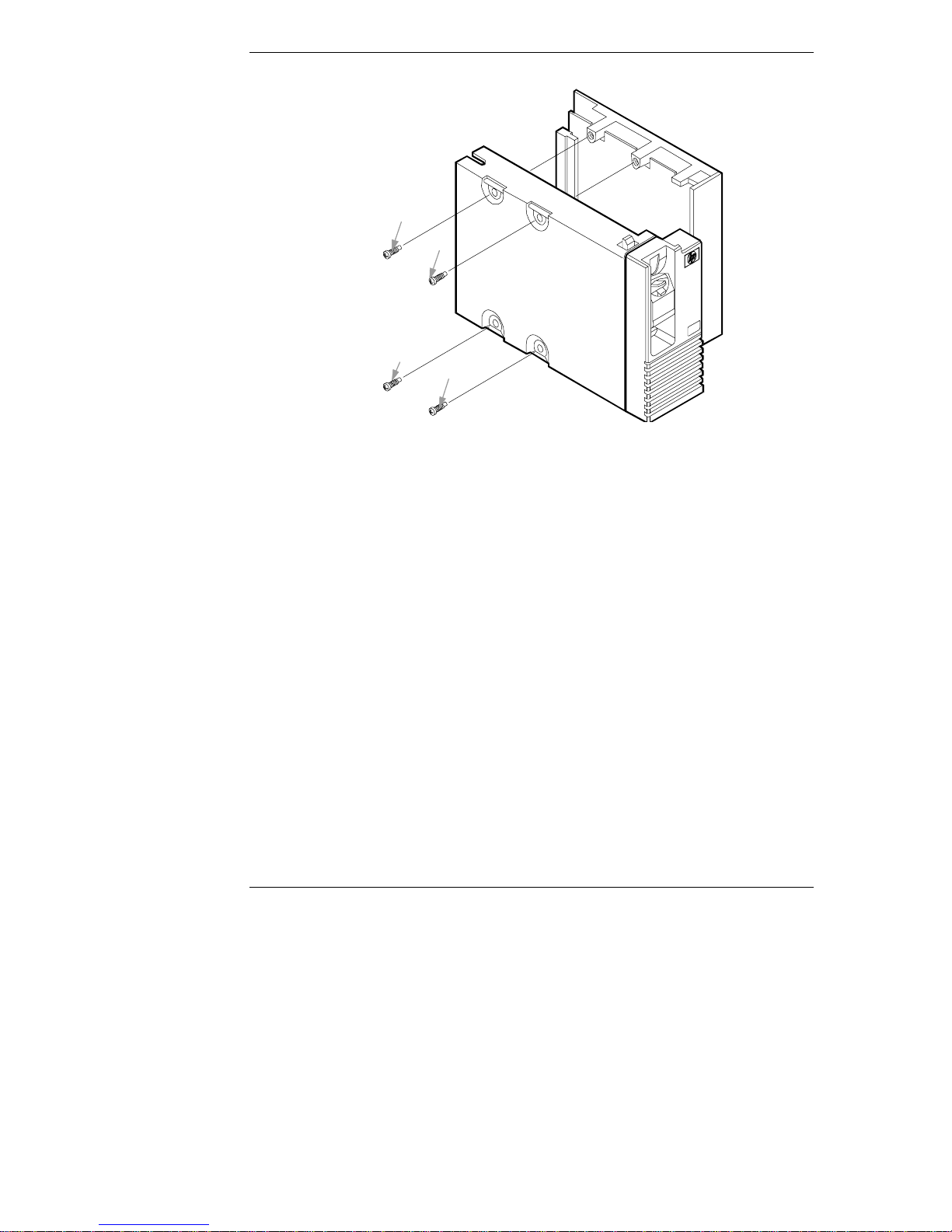
2. Attach the drive to the hot swap tray with the screws provided in the order
shown in Figure 1-1.
1
Page 6
Chapter 1 Installation Procedure
2
3
1
4
Figure 1-1. Hot Swap Hard Disk Drive and Tr ay Instal lation
Unpacking and Shipping
Your system has a shipping plug to ensure that the hot swap hard disk drive is
not damaged while it is being transported. Save this plug. If you plan to transport
your system, reinstall your shipping plug as shown in Figure 1-2.
2
Page 7

Chapter 1 Installation Procedure
Figure 1-2. Shi ppi ng Plug
Installing the Hot Swap Hard Disk Drive
CAUTION Use one of the six (6) vertical shelves in the system. Do not
attempt to install the hot swap hard disk drive in the
horizontal shelves.
Protect the hot swap hard disk drive from static electricity by
leaving it in its antistatic bag until you are ready to install it.
Before handling the hard disk drive, touch any unpainted
metal surface to discharge static electricity. When you remove
the hard disk drive from the antistatic bag, handle it only by
the frame.
Do not touch th e electrical components. P lace the hard d isk
drive on the antistatic bag whenever you set it down.
1. If there is a filler panel in the disk shelf, remove that panel.
2. On the hot swap hard disk drive, press the locking tab down, and lift the
lever up as far as it can go. (See Figure 1-3.) Lifting the lever retracts the
locking pin at the top of the hard disk drive.
3
Page 8

Chapter 1 Installation Procedure
3. Holding the hard disk drive as shown in Figure 1-3, slide the hot swap
hard disk drive slowly into the shelf until it stops.
4. Press the lever down as far as it will go.
Figure 1-3. Inst al ling the Hot Swap Hard Disk Drive
Removing the Hot Swap Hard Disk Drive
1. To unlock the hot swap hard disk drive, push the tab down and then lift
the front lever.
2. Pull the hard disk drive out about an inch (2.5 cm) to break the power
connection.
3. Wait about 30 seconds for the hard disk drive to stop spinning and the
drive heads to park.
4. Use your hand to support th e bottom of the hard disk drive, as shown in
Figure 1-4. Slowly pull the h ard disk drive straigh t out. Do not allow the
hard disk drive to fall.
5. Turn the hard disk drive slowly to its horizontal storage orientation.
6. Place the hard disk drive in an electrostatic protected container. Do not
stack hot swap hard disk drives.
4
Page 9

Chapter 1 Installation Procedure
Figure 1-4. Rem oving the Hot Swap Hard Disk Drive
5
Page 10

Page 11

2 Disk Drive Characteristics
The proper settings for the following items will depend on the operating system
(NetWare, MS- DOS, OS/2, Win d ows NT, UNIX, or Banyan Vines) and
corresponding version number:
•
Extended Translation setting for the controller
•
Partitions, logical drives or divisions for the hot swap hard disk drive
For non-UNIX systems, partition and logical hot swap hard disk drive sizes also
depend on:
•
Partition type (Bootable or Non-bootable)
•
Fi le system (FAT, HPFS, NTFS)
To determine the appropriate controller and disk drive configuration, consult the
section below for your operating system.
NetWare and DOS
NOTE If you want to write core dumps onto the hard disk drive,
ensure that the drive has enough space for a complete image of
your total memory.
Table 2-1. Partitioning Inf or mation f or NetWare and DOS
System
Software
on Disk Disk Use
NetWare
with
DOS
NetWare
only
DOS
only
DOS
only
Operating
system and
data
Data only Disabl ed None None N/A
Operating
system
Data only Enabled None Disk capacity 2 GB
Extended
Translation
for > 1 GB
Drive
Disabled 30-50 MB
Enabled 2 GB
Primary
(Boot)
Partition
recommended,
1 GB
maximu m for
DOS
maximu m
Extended
Partition
None N/A
Rest of disk 2 GB
Logical
Disk
maximum
maximum
7
Page 12

Chapter 2 Disk Drive Characteristics
OS/2 and Windows NT
NOTE Configure the controller with “Extended Translation for
Drives > 1 GB ” enabled.
Table 2-2. Partitioning Inf or mation f or OS/2 and Windows NT
Maximum Bootable Partition Maximum Non-boot able Drive
Operating
System
OS/2 2.X
OS/2 Warp
Family
Windows
NT 3.1
Windows NT
3.5
Windows NT
3.51
Windows NT
4.0
FAT or HPFS NTFS FAT HPFS NTFS
2 GB N/A 2 GB 64 GB N/A
2 GB N/A 2 GB 64 GB N/A
2 GB 2 GB 2 GB Disk capa ci t y Disk
capacity
2 GB 2 GB 2 GB Disk capa ci t y Disk
capacity
4 GB 4 GB 4 GB Disk capa ci t y Disk
capacity
4 GB 4 GB 4 GB N/A Disk
capacity
8
Page 13

Chapter 2 Disk Drive Characteristics
UNIX and Banyan Vines
Table 2-3. Part i tioning Informati on f or UNIX
Maximum Size Maximum Number
Operating
System
SCO UNIX
3.2.4.2 and
ODT/OS 3.0
SCO UNIX
3.2v5.0 and OS
5.0.X
UnixWare 1.1
UnixWare 2.0.X
UnixWare 2.1.X
Banyan VINES
5.54 and 6.X,
7.X
Extended
Translation
for > 1 GB
Drive
Disabled Disk
Disabled Disk
Disabled Disk
Disabled Disk
Disabled Disk
Disabled Disk
Partition
capacity
capacity
capacity
capacity
capacity
capacity
File system
(division)
1 GB (root )
2 GB (data)
1 TB 4 7
2 GB 4 16 slices
2 GB - 1 TB 4 16 slices
2 GB - 1 TB 4 184 slices
2 GB 1 N/A
Partitions
on Disk
47
Divisions
in
Partition
9
Page 14

Page 15

3 A pplication A lerts
D4903A Cooling Requirements
The D4903A mass storage device is the first of a family of high performance
10K RPM drives. Adequate cooling is very importan t. T he D4903A drive is
currently supported in the LH Plus, LH Pro, LD Pro, LX Pro, LXe Pro, and
Storage System/6. Th e dri ve is not supported in the LH and LS.
D3604A /B Storage Sy stem/6 using Ultra SCSI
Drives
Ultra SCSI is an industry standard for transferring data. HP NetServer drives that
come installed as part of Ultra Hot Swap drive accessori es are Ultra S C SI
capable. However, Ultra SCSI requires that all components of the system be Ultra
SCSI ca p able, i nclu d ing the contr ol ler, th e d rives, an d the connect ions. S ince t he
D3604A/B Storage System/6 is Fast SCSI (20 MB/sec) capable but not Ultra
SCSI capable, this drive cannot be used in Ultra SCSI mode when installed into a
D3604A/B Storage System/6.
Fast SCSI (not Ultra SCSI) must be enabled in the host system, if it is connected
to the Storage System/6 with Ultra SCSI drives installed. Complete information
on using Ultra SCSI in your NetServer can be found on the HP NetServer "News
Updates and Information" web page at:
http://www.hp.com:80/netserver/support/news_main.html
under "Using Ultra SCSI in your HP NetServer"
Hot Swap Drives Must be Parked Prior to
Removal
To prevent handling damage (for example, head slaps or head actuator
unlocking) to a good drive during removal, perform the following steps:
1. Unlatch the drive.
2. Pull the drive out about an inch (2.5 cm) to break the power connection.
3. Wait about 30 seconds for the drive to stop spinning and th e drive heads
to park.
4. Carefully remove the drive.
11
Page 16

Page 17

A Warranty and Support
The hardware warranty below applies to components purchased as accessories. If
your component was factory installed as part of a HP NetServer model, refer to
the Warranty Statement provided with your system documentation.
Hardware Warranty
This HP NetServer accessory is covered by a limited hardware warranty for a
peri od of on e year from receip t by the original end-user purchaser .
Once installed in an HP NetServer, this accessory may carry the lon g er of either a
one-year warranty or the remainder of the warranty period for the HP NetServer
in which it is installed.
This accessory may be serviced through expedited part shipment. In this event,
HP will prepay shipping charges, duty, and taxes; provide telephone assistance
on replacement of the component; and pay shipping charges, duty, and taxes for
any part that HP asks to be returned.
The customer may be required to run HP-supplied configuration and diagnostic
programs before a replacement will be dispatched or an on-site visit is
authorized.
Refer to the Warranty Statement provided with your original HP NetServer
system documentation for the warranty limitations, customer responsibilities, and
other terms and conditions.
HP Repair and Telephone Support
Refer to the HP Warranty and Service/Support Booklet section of your
HP NetServer system documentation for instructions on how to obtain
HP repair and telephone support.
HP Wo r l d Wi d e We b S i t e
Refer to the following World Wid e Web (WWW) site for tech nica l specifi cations
on Hewlett-Packard hard disk drives:
http://www.hp.com:80/netserver/support/news_main.html
13
Page 18

Page 19

B Regulatory Information
DECLARATION OF CONFO RM IT Y
according to IS O /IEC Guid e 22 and E N 45014
Manufacturer’s Name: Hewlett-Packard Company
Address: 10955 Tantau Avenue
Cupertino, CA 95052
declares, that the product
Product Name: Hot Swap Hard Disk Drives
Model Number(s): D3581A, D3582A, D3582C, D3583A, D3583C, D4289A
D5039A, D6019A, D7050A
Product Options: N/A
conforms to the following Product Specifications:
Safety: IEC 950:1991 + A1, A2 / EN 60950 (1992) + A1, A2
EMC: CISPR 22:1993 / EN 55022 (1994) - Class B
EN 50082-1:1992 - Generic Immunit y
IEC 801-2:1991, 4 kV CD, 8 kV AD
IEC 801-3:1984, 3V/m
IEC 801-4:1988, 0.5 kV Signal Lin es, 1 kV Power Lines
1)
Supplementary Information:
The product herewith complies with the requirements of the following directives, and
carries the CE-ma rk a ccordingly:
o Low Voltage Directive 72/23/EEC
o EMC Directive 89/336/EEC
1) This product was tested in a typical configuration with a Hewlett-Packard NetServer
computer and peripher al s.
Cupertino, February 8, 2000
Nigel Marrion/Quality Engineering Manager
European Contact: Your local Hewlett-Packard Sales and Service Office or Hewlett-Packard GmbH, Department
ZQ / Standards Euro pe, Herrenberger Straße 130, D-7030 Böbl inge n (FAX: + 49-7031-143143)
15
 Loading...