

Page 1

HP LaserJet M2727 MFP Series
Service Manual
Page 2

Page 3

HP LaserJet M2727 MFP Series
Service Manual
Page 4

Copyright information
Safety information
Trademark credits
© 2007 Copyright Hewlett-Packard
Development Company, L.P.
Reproduction, adaptation, or translation
without prior written permission is prohibited,
except as allowed under the copyright laws.
The information contained herein is subject
to change without notice.
The only warranties for HP products and
services are set forth in the express warranty
statements accompanying such products
and services. Nothing herein should be
construed as constituting an additional
warranty. HP shall not be liable for technical
or editorial errors or omissions contained
herein.
Part number CB532-90946
Edition 1, 11/2007
WARNING!
Potential Shock Hazard
Always follow basic safety precautions when
using the product to reduce risk of injury from
fire or electric shock.
Read and understand all instructions in the
user guide.
Observe all warnings and instructions
marked on the product.
Use only a grounded electrical outlet when
connecting the product to a power source. If
you do not know whether the outlet is
grounded, check with a qualified electrician.
Do not touch the contacts on the end of any
of the sockets on the product. Replace
damaged cords immediately.
Unplug the product from wall outlets before
cleaning.
Do not install or use the product near water
or when you are wet.
Install the product securely on a stable
surface.
Microsoft® and Windows® are U.S.
registered trademarks of Microsoft
Corporation.
Windows Vista™ is either a registered
trademark or trademark of Microsoft
Corporation in the United States and/or other
countries.
Linux is a U.S. registered trademark of Linus
Torvalds.
UNIX® is a registered trademark of The
Open Group.
PostScript® is a trademark of Adobe
Systems Incorporated.
Energy Star® and the Energy Star logo® are
U.S. registered marks of the United States
Environmental Protection Agency.
Install the product in a protected location
where no one can step on or trip over the
power cord and where the power cord will not
be damaged.
If the product does not operate normally, see
the online user guide.
Refer all servicing questions to qualified
personnel.
Information regarding FCC Class B, Parts 15
and 68 requirements can be found in the user
guide.
Page 5

Table of contents
1 Product information
Quick access to product information .................................................................................................... 2
Product comparison ............................................................................................................................. 3
Product features ................................................................................................................................... 4
Product walkaround .............................................................................................................................. 5
Front view ............................................................................................................................ 5
Back view ............................................................................................................................. 6
Interface ports ...................................................................................................................... 6
Control panel ....................................................................................................................... 7
Serial number and model number location ........................................................................................... 8
Software description ............................................................................................................................. 9
Supported operating systems .............................................................................................. 9
Supported printer drivers ..................................................................................................... 9
Software included with the product ...................................................................................... 9
Recommended installation for Windows ........................................................... 10
Express installation (USB or network) ............................................................... 10
Macintosh software ........................................................................................... 10
Software for Windows ........................................................................................................................ 12
HP ToolboxFX ................................................................................................................... 12
Embedded Web server (EWS) .......................................................................................... 12
Software for Macintosh ....................................................................................................................... 13
HP Director ........................................................................................................................ 13
Macintosh Configure Device (Mac OS X v10.3, v10.4, and later) ..................................... 13
PDEs (Mac OS X v10.3, v10.4, and later) ......................................................................... 14
Uninstall software ............................................................................................................................... 15
Windows ............................................................................................................................ 15
Macintosh .......................................................................................................................... 15
Media specifications ........................................................................................................................... 16
Supported paper and print media sizes ............................................................................. 16
Media to avoid ................................................................................................................... 17
Media that can damage the product .................................................................................. 17
2 Installation
Operating environment ....................................................................................................................... 20
Minimum system requirements .......................................................................................... 21
Unpack the product ............................................................................................................................ 22
Install input devices ............................................................................................................................ 23
ADF input tray .................................................................................................................... 23
250-sheet input tray (tray 3) ............................................................................................... 24
ENWW iii
Page 6

Install the control-panel faceplate ....................................................................................................... 25
Load paper and print media ............................................................................................................... 26
Install memory DIMMs ........................................................................................................................ 30
3 Maintenance
Manage supplies ................................................................................................................................ 34
Clean the product ............................................................................................................................... 49
Manage the product ........................................................................................................................... 58
Load documents to fax, copy, or scan ............................................................................... 26
Tray 1 ................................................................................................................................. 27
Tray 2 or 3 ......................................................................................................................... 28
Configure trays .................................................................................................................. 29
Change tray selection ........................................................................................................ 29
Information ......................................................................................................................... 30
Install a memory DIMM ..................................................................................................... 30
Life expectancies of supplies and the product ................................................................... 34
Order supplies ................................................................................................................... 34
Store print cartridges ......................................................................................................... 35
Replace and recycle supplies ............................................................................................ 35
Replace print cartridge ....................................................................................................... 37
Load staples ...................................................................................................................... 39
Replace the tray 2 pickup roller ......................................................................................... 40
Replace the tray 2 and optional tray 3 separation pad ...................................................... 45
HP policy on non-HP supplies ........................................................................................... 48
Reset the product for non-HP supplies ............................................................. 48
HP fraud hotline ................................................................................................................. 48
Clean the exterior .............................................................................................................. 49
Clean the flatbed scanner glass ........................................................................................ 49
Clean the scanner-cover backing ...................................................................................... 51
Clean the tray 2 pickup roller ............................................................................................ 52
Clean the ADF pickup-roller assembly .............................................................................. 55
Clean the paper path ......................................................................................................... 56
Clean the paper path from HP ToolboxFX ........................................................ 57
Clean the paper path from the product control panel ........................................ 57
HP ToolboxFX ................................................................................................................... 58
View the HP ToolboxFX .................................................................................... 58
Status ................................................................................................................ 58
Event log ........................................................................................... 59
Alerts ................................................................................................................. 59
Set up status alerts ........................................................................... 59
Set up e-mail alerts ........................................................................... 59
Fax .................................................................................................................... 59
Fax tasks .......................................................................................... 60
Fax phone book ................................................................................ 60
Fax send log ..................................................................................... 62
Fax receive log ................................................................................. 62
Help (Documentation) ....................................................................................... 62
System settings ................................................................................................. 63
Device information ............................................................................ 63
Paper handling ................................................................................. 64
iv ENWW
Page 7

Embedded Web server ...................................................................................................... 66
Macintosh Configure Device (Mac OS X v10.3, v10.4, and later) ..................................... 67
4 Theory of operation
Basic operation ................................................................................................................................... 70
Sequence of operation for the base unit ............................................................................ 70
Scanner and ADF functions and operation ........................................................................................ 72
Scanner functions ............................................................................................................. 72
Scanner operation ............................................................................................................. 73
ADF operation .................................................................................................................... 73
ADF paper path and ADF sensors ..................................................................................... 74
ADF jam detection ............................................................................................................. 75
Internal components (base unit) ......................................................................................................... 76
Engine control system ........................................................................................................................ 78
Laser/scanner system ........................................................................................................................ 80
Pickup/feed/delivery system ............................................................................................................... 81
Image-formation system .................................................................................................................... 83
Fax functions and operation .............................................................................................................. 87
Computer and network security features ........................................................................... 87
PSTN operation ................................................................................................................. 87
Receive faxes when you hear fax tones ............................................................................ 87
Distinctive ring function ...................................................................................................... 88
Fax by using Voice over IP services .................................................................................. 88
The fax subsystem ............................................................................................................. 89
Fax card in the fax subsystem ........................................................................................... 89
Fax page storage in flash memory .................................................................................... 91
Print quality ....................................................................................... 64
Paper types ...................................................................................... 64
System setup .................................................................................... 65
Service .............................................................................................. 65
Device Polling ................................................................................... 65
Print settings ..................................................................................................... 65
Printing ............................................................................................. 65
PCL 5e .............................................................................................. 66
PostScript ......................................................................................... 66
Network settings ................................................................................................ 66
Features ............................................................................................................ 66
Secure the embedded Web server ................................................................... 67
Safety isolation .................................................................................................. 89
Safety-protection circuitry .................................................................................. 89
Data path ........................................................................................................... 90
Hook state ......................................................................................................... 90
Downstream device detection ........................................................................... 90
Hook switch control ........................................................................................... 90
Ring detect ........................................................................................................ 91
Line current control ........................................................................................... 91
Billing- (metering-) tone filters ........................................................................... 91
Stored fax pages ............................................................................................... 91
Advantages of flash memory storage ............................................................... 91
ENWW v
Page 8

5 Removal and replacement
Introduction ......................................................................................................................................... 94
Removal and replacement strategy .................................................................................. 94
Electrostatic discharge ....................................................................................................... 94
User-replaceable parts ...................................................................................................... 94
Required tools ................................................................................................................... 95
Before performing service .................................................................................................. 95
After performing service ..................................................................................................... 96
Post-service tests .............................................................................................................. 96
Parts removal order ........................................................................................................... 98
Remove the print cartridge ................................................................................................ 99
External panels, covers, and doors .................................................................................................. 100
Right cover ....................................................................................................................... 100
Left cover ......................................................................................................................... 102
Print-cartridge door .......................................................................................................... 104
Rear cover ....................................................................................................................... 106
Top cover ......................................................................................................................... 108
Replace the ADF pickup-roller assembly ......................................................................................... 110
ADF scanner glass ........................................................................................................................... 113
ADF assembly .................................................................................................................................. 115
Scanner/ADF assembly .................................................................................................................... 117
Bezel and control panel .................................................................................................................... 119
Internal assemblies .......................................................................................................................... 122
Convenience-stapler assembly (HP LaserJet M2727nfs only) ........................................ 122
Convenience-stapler power supply (HP LaserJet M2727nfs only) .................................. 124
Convenience-stapler AC inlet cable (HP LaserJet M2727nfs only) ................................. 126
Convenience-stapler power supply bracket and strap (HP LaserJet M2727nfs only) ..... 127
Speaker ........................................................................................................................... 128
Power-switch PCA ........................................................................................................... 130
Formatter ......................................................................................................................... 132
Duplex assembly ............................................................................................................. 135
Laser/scanner (print engine) ............................................................................................ 137
Memory-tag-reader assembly (E-label reader) ................................................................ 139
Fan ................................................................................................................................... 141
Duplex-drive gears ........................................................................................................... 143
Duplex solenoid ............................................................................................................... 145
Fuser ................................................................................................................................ 147
Interlock assembly ........................................................................................................... 152
Engine controller assembly (ECU) ................................................................................... 153
Main motor ....................................................................................................................... 158
Pickup-and-feed assemblies ............................................................................................ 160
Registration-roller assembly ............................................................................................ 161
Main gear assembly and tray 2 pickup solenoid .............................................................. 162
Test 1 (print-quality test) ................................................................................... 96
Test 2 (copy-quality test) ................................................................................... 96
Test 3 (fax-quality test) ...................................................................................... 97
Transfer roller .................................................................................................. 160
6 Solve problems
Problem-solving checklist ................................................................................................................. 166
vi ENWW
Page 9

Control-panel messages .................................................................................................................. 169
Alert and warning messages .......................................................................................... 169
Alert and warning message tables .................................................................. 169
Critical error messages .................................................................................................... 177
Critical error message-tables .......................................................................... 177
Clear jams ........................................................................................................................................ 179
Causes of jams ................................................................................................................ 179
Where to look for jams ..................................................................................................... 180
Clear jams from the ADF ................................................................................................. 180
Clear jams from the input-tray areas ............................................................................... 182
Clear jams from the duplexer ........................................................................................... 184
Clear jams from the output-bin areas .............................................................................. 186
Top (face-down) output bin ............................................................................. 186
Rear (face-up) output bin ................................................................................ 187
Clear jams from the print-cartridge area .......................................................................... 188
Clear jams from the convenience stapler (HP LaserJet M2727nfs MFP only) ................ 189
Avoid repeated jams ....................................................................................................... 190
Control-panel menus ........................................................................................................................ 191
Use the control-panel main menus .................................................................................. 191
Control-panel main menus ............................................................................................... 191
Control-panel secondary menus ...................................................................................... 199
Use the control-panel secondary menus ......................................................... 199
Control-panel secondary menus ..................................................................... 199
Print problems .................................................................................................................................. 204
Print-quality problems ...................................................................................................... 204
Improve print quality ........................................................................................ 204
Print-quality settings ....................................................................... 204
Identify and correct print defects ..................................................................... 205
Print-quality checklist ...................................................................... 205
General print-quality issues ............................................................ 205
Scan problems ................................................................................................................................. 211
Solve scanned-image problems ...................................................................................... 211
Scan-quality problems ..................................................................................................... 213
Prevent problems ............................................................................................ 213
Solve scan-quality problems ........................................................................... 213
Copy problems ................................................................................................................................. 214
Prevent problems ............................................................................................................. 214
Image problems ............................................................................................................... 214
Media-handling problems ................................................................................................ 215
Performance problems .................................................................................................... 217
Fax problems .................................................................................................................................... 218
General fax problem-solve ............................................................................................... 218
Problems receiving faxes ................................................................................................. 219
Problems sending faxes .................................................................................................. 222
Voice-call problems ......................................................................................................... 224
Media-handling problems ................................................................................................ 225
Performance problems .................................................................................................... 226
Control-panel display problems ........................................................................................................ 227
Convenience-stapler problems (HP LaserJet M2727nfs only) ......................................................... 227
DSL problems ................................................................................................................................... 228
ENWW vii
Page 10

PABX line problems ......................................................................................................... 228
ADF problems .................................................................................................................................. 229
Functional checks ............................................................................................................................. 230
Drum rotation test ............................................................................................................ 230
Engine test ....................................................................................................................... 231
Half self-test functional check .......................................................................................... 232
Perform a half self-test check .......................................................................................... 232
Perform other checks ....................................................................................................... 232
Heating element check .................................................................................................... 233
High-voltage contacts check ............................................................................................ 233
Check the print-cartridge contacts ................................................................ 233
Check the high-voltage connector assembly ................................................. 234
Service-mode functions .................................................................................................................... 235
NVRAM initialization ........................................................................................................ 235
Super NVRAM initialization .............................................................................................. 235
Service menu ................................................................................................................... 235
Problem-solve tools .......................................................................................................................... 237
Product information pages and reports ............................................................................ 237
Configuration page .......................................................................................... 237
Supplies Status page ...................................................................................... 237
PCL, PCL 6, or PS font list .............................................................................. 237
Demo page ...................................................................................................... 238
Usage page ..................................................................................................................... 238
Menu map ........................................................................................................................ 238
Network report ................................................................................................................. 238
Fax reports ....................................................................................................................... 239
Fax activity log ................................................................................................ 239
Fax call report ................................................................................................. 239
Phone book report ........................................................................................... 239
Billing-code report ........................................................................................... 240
HP ToolboxFX ................................................................................................................. 240
To view HP ToolboxFX ................................................................................... 240
Troubleshooting tab ........................................................................................ 240
Service menu .................................................................................................................. 241
Restore the factory-set defaults ...................................................................... 241
Clean the paper path ....................................................................................... 241
T.30 protocol trace .......................................................................................... 242
Archive print .................................................................................................... 242
Firmware updates ............................................................................................................................. 243
Firmware update by using a flash executable file ............................................................ 243
7 Parts
Accessories and ordering information .............................................................................................. 247
Supplies ............................................................................................................................................ 248
Memory ............................................................................................................................................ 248
Cable and interface accessories ...................................................................................................... 248
Paper-handling accessories ............................................................................................................ 249
Whole unit replacement .................................................................................................................... 250
Scanner/ADF replacement parts ...................................................................................................... 254
Control-panel bezels ........................................................................................................................ 255
viii ENWW
Page 11

Supplementary documentation and support ..................................................................................... 257
Problem-solve diagrams ................................................................................................................... 259
Repetitive image defects ................................................................................................. 259
Interface connectors ....................................................................................................... 260
Formatter connectors ....................................................................................................... 260
Fax card ........................................................................................................................... 261
Solenoids ......................................................................................................................... 262
Switches and sensors ...................................................................................................... 263
Rollers and pads .............................................................................................................. 264
PCAs (base unit) .............................................................................................................. 265
Major components (base unit) ......................................................................................... 266
Scanner and ADF ............................................................................................................ 267
Circuit diagram (1 of 2) .................................................................................................... 268
Circuit diagram (2 of 2) .................................................................................................... 268
Parts lists and diagrams ................................................................................................................... 270
Types of screws ............................................................................................................... 271
Scanner and ADF assemblies .......................................................................................................... 272
Scanner components ....................................................................................................................... 274
ADF components .............................................................................................................................. 276
Convenience stapler components (HP LaserJet M2727nfs only) .................................................... 278
Formatter, fax card, HP jewel, and nameplate ................................................................................. 280
External covers and panels .............................................................................................................. 282
Cartridge door assembly .................................................................................................................. 284
Internal components (1 of 4) ............................................................................................................ 286
Internal components (2 of 4) ............................................................................................................ 288
Internal components (3 of 4) ............................................................................................................ 290
Internal components (4 of 4) ............................................................................................................ 292
Engine-controller assembly (ECU) ................................................................................................... 294
Main-drive assembly ........................................................................................................................ 296
Duplexing-drive assembly ................................................................................................................ 298
Tray 2 cassette and tray 3 cassette/feeder ...................................................................................... 300
Duplexing assembly ......................................................................................................................... 302
Fuser assembly ................................................................................................................................ 304
Alphabetical parts list ....................................................................................................................... 306
Numerical parts list ........................................................................................................................... 312
Appendix A Service and support
Hewlett-Packard limited warranty statement .................................................................................... 319
Print cartridge limited warranty statement ........................................................................................ 321
Appendix B Specifications
Physical specifications ..................................................................................................................... 324
Electrical specifications .................................................................................................................... 324
Power consumption .......................................................................................................................... 324
Environmental specifications ............................................................................................................ 325
Acoustic emissions ........................................................................................................................... 325
Appendix C Regulatory information
FCC compliance ............................................................................................................................... 328
ENWW ix
Page 12

Environmental product stewardship program ................................................................................... 329
Protecting the environment .............................................................................................. 329
Ozone production ............................................................................................................ 329
Power consumption ......................................................................................................... 329
Toner consumption .......................................................................................................... 329
Paper use ........................................................................................................................ 329
Plastics ............................................................................................................................ 329
HP LaserJet print supplies ............................................................................................... 329
Return and recycling instructions ..................................................................................... 330
United States and Puerto Rico ........................................................................ 330
Multiple returns (two to eight cartridges) ........................................ 330
Single returns ................................................................................. 330
Shipping .......................................................................................... 330
Non-US returns ............................................................................................... 330
Paper ............................................................................................................................... 330
Material restrictions .......................................................................................................... 330
Disposal of waste equipment by users in private households in the European Union .... 331
Material Safety Data Sheet (MSDS) ................................................................................ 331
For more information ....................................................................................................... 332
Telephone Consumer Protection Act (United States) ...................................................................... 333
IC CS-03 requirements ..................................................................................................................... 333
EU statement for telecom operation ................................................................................................. 334
New Zealand telecom statements .................................................................................................... 334
Declaration of conformity .................................................................................................................. 335
Safety statements ............................................................................................................................. 336
Laser safety ..................................................................................................................... 336
Canadian DOC regulations .............................................................................................. 336
EMI statement (Korea) ..................................................................................................... 336
Laser statement for Finland ............................................................................................. 337
Substances table (China) ................................................................................................ 338
Index ................................................................................................................................................................. 339
x ENWW
Page 13

List of tables
Table 1-1 Product guides ................................................................................................................................... 2
Table 1-2 Supported printer drivers .................................................................................................................... 9
Table 1-3 Supported paper and print media sizes ........................................................................................... 16
Table 1-4 Supported envelopes and postcards ............................................................................................... 17
Table 1-5 ADF .................................................................................................................................................. 17
Table 4-1 Sequence of operation ..................................................................................................................... 70
Table 4-2 Power-on sequence ......................................................................................................................... 71
Table 6-1 Alert and warning messages ......................................................................................................... 169
Table 6-2 Alert and warning messages ......................................................................................................... 172
Table 6-3 Critical error messages .................................................................................................................. 177
Table 6-4 Fax Job status menu ...................................................................................................................... 191
Table 6-5 Fax functions menu ........................................................................................................................ 191
Table 6-6 Copy setup menu ........................................................................................................................... 192
Table 6-7 Reports menu ................................................................................................................................. 193
Table 6-8 Fax setup menu ............................................................................................................................. 194
Table 6-9 System setup menu ....................................................................................................................... 197
Table 6-10 Service menu ............................................................................................................................... 199
Table 6-11 Secondary service menu .............................................................................................................. 200
Table 6-12 Developer's menu ........................................................................................................................ 201
Table 7-1 Whole unit replacement, product bundle CB532A ......................................................................... 250
Table 7-2 Whole unit replacement, product bundle CB533A ......................................................................... 252
Table 7-3 Control-panel bezels ...................................................................................................................... 255
Table 7-4 Service and training support .......................................................................................................... 257
Table 7-5 User guides .................................................................................................................................... 257
Table 7-6 Getting started guide ...................................................................................................................... 258
Table 7-7 Technical support Web sites .......................................................................................................... 258
Table 7-8 Repetitive image defects ................................................................................................................ 259
Table 7-9 Interface connectors ....................................................................................................................... 260
Table 7-10 Formatter connectors ................................................................................................................... 260
Table 7-11 Fax card ....................................................................................................................................... 261
Table 7-12 Solenoids ..................................................................................................................................... 262
Table 7-13 Switches and sensors .................................................................................................................. 263
Table 7-14 Rollers and pads .......................................................................................................................... 264
Table 7-15 PCAs (base unit) .......................................................................................................................... 265
Table 7-16 Major components (base unit) ..................................................................................................... 266
Table 7-17 Scanner and ADF ......................................................................................................................... 267
Table 7-18 Scanner and ADF assemblies ..................................................................................................... 273
Table 7-19 Scanner components ................................................................................................................... 275
Table 7-20 ADF components ......................................................................................................................... 277
ENWW xi
Page 14

Table 7-21 Convenience stapler components (HP LaserJet M2727nfs only) ................................................ 279
Table 7-22 Formatter, Fax card, HP jewel, and nameplate ........................................................................... 281
Table 7-23 External covers and panels .......................................................................................................... 283
Table 7-24 Cartridge door assembly .............................................................................................................. 285
Table 7-25 Internal components (1 of 4) ........................................................................................................ 287
Table 7-26 Internal components (2 of 4) ........................................................................................................ 289
Table 7-27 Internal components (3 of 4) ........................................................................................................ 291
Table 7-28 Internal components (4 of 4) ........................................................................................................ 293
Table 7-29 Engine-controller assembly .......................................................................................................... 295
Table 7-30 Main-drive assembly .................................................................................................................... 297
Table 7-31 Duplexing-drive assembly ............................................................................................................ 299
Table 7-32 Tray 2 cassette and tray 3 cassette/feeder .................................................................................. 301
Table 7-33 Duplexing assembly ..................................................................................................................... 303
Table 7-34 Fuser assembly ............................................................................................................................ 305
Table 7-35 Alphabetical parts list ................................................................................................................... 306
Table 7-36 Numerical parts list ....................................................................................................................... 312
Table B-1 Physical specifications ................................................................................................................... 324
Table B-2 Electrical specifications .................................................................................................................. 324
Table B-3 Power consumption (average, in watts), ...................................................................................... 324
Table B-4 Environmental specifications ........................................................................................................ 325
Table B-5 Acoustic emissions ....................................................................................................................... 325
xii ENWW
Page 15

List of figures
Figure 2-1 Operating environment ................................................................................................................... 20
Figure 2-2 HP LaserJet M2727 MFP package contents .................................................................................. 22
Figure 2-3 Install the ADF input tray ................................................................................................................. 23
Figure 2-4 Install the 250-sheet input tray ........................................................................................................ 24
Figure 2-5 Install the control-panel faceplate ................................................................................................... 25
Figure 2-6 Load a document onto the flatbed scanner .................................................................................... 26
Figure 2-7 Load documents into the ADF (1 of 2) ............................................................................................ 27
Figure 2-8 Load documents into the ADF (2 of 2) ............................................................................................ 27
Figure 3-1 Replace the tray 2 pickup roller (1 of 7) .......................................................................................... 40
Figure 3-2 Replace the tray 2 pickup roller (2 of 7) .......................................................................................... 41
Figure 3-3 Replace the tray 2 pickup roller (3 of 7) .......................................................................................... 41
Figure 3-4 Replace the tray 2 pickup roller (4 of 7) .......................................................................................... 42
Figure 3-5 Replace the tray 2 pickup roller (5 of 7) .......................................................................................... 42
Figure 3-6 Replace the tray 2 pickup roller (6 of 7) .......................................................................................... 43
Figure 3-7 Replace the tray 2 pickup roller (7 of 7) .......................................................................................... 43
Figure 3-8 Replace the tray 2 or tray 3 separation pad (1 of 6) ....................................................................... 45
Figure 3-9 Replace the tray 2 or tray 3 separation pad (2 of 6) ....................................................................... 45
Figure 3-10 Replace the tray 2 or tray 3 separation pad (3 of 6) ..................................................................... 46
Figure 3-11 Replace the tray 2 or tray 3 separation pad (4 of 6) ..................................................................... 46
Figure 3-12 Replace the tray 2 or tray 3 separation pad (5 of 6) ..................................................................... 47
Figure 3-13 Replace the tray 2 or tray 3 separation pad (6 of 6) ..................................................................... 47
Figure 3-14 Clean the scanner glass (1 of 2) ................................................................................................... 49
Figure 3-15 Clean the scanner glass (2 of 2) ................................................................................................... 50
Figure 3-16 Clean the scanner-cover backing ................................................................................................. 51
Figure 3-17 Clean the tray 2 pickup roller (1 of 6) ............................................................................................ 52
Figure 3-18 Clean the tray 2 pickup roller (2 of 6) ............................................................................................ 52
Figure 3-19 Clean the tray 2 pickup roller (3 of 6) ............................................................................................ 52
Figure 3-20 Clean the tray 2 pickup roller (4 of 6) ............................................................................................ 53
Figure 3-21 Clean the tray 2 pickup roller (5 of 6) ............................................................................................ 53
Figure 3-22 Clean the tray 2 pickup roller (6 of 6) ............................................................................................ 54
Figure 3-23 Clean the ADF pickup-roller assembly (1 of 5) ............................................................................. 55
Figure 3-24 Clean the ADF pickup-roller assembly (2 of 5) ............................................................................. 55
Figure 3-25 Clean the ADF pickup-roller assembly (3 of 5) ............................................................................. 55
Figure 3-26 Clean the ADF pickup-roller assembly (4 of 5) ............................................................................. 56
Figure 3-27 Clean the ADF pickup-roller assembly (5 of 5) ............................................................................. 56
Figure 4-1 HP LaserJet M2727 MFP system block diagram ............................................................................ 70
Figure 4-2 Optical system ................................................................................................................................ 72
Figure 4-3 ADF paper path ............................................................................................................................... 74
Figure 4-4 Cross-section of printer ................................................................................................................... 76
ENWW xiii
Page 16

Figure 4-5 Engine control system ..................................................................................................................... 78
Figure 4-6 Engine-control-system circuit diagram ............................................................................................ 79
Figure 4-7 Laser/scanner system ..................................................................................................................... 80
Figure 4-8 Pickup/feed/delivery system ........................................................................................................... 82
Figure 4-9 Image-formation system ................................................................................................................. 83
Figure 4-10 Primary charging ........................................................................................................................... 83
Figure 4-11 Developing .................................................................................................................................... 84
Figure 4-12 Transfer ......................................................................................................................................... 85
Figure 4-13 Separation ..................................................................................................................................... 85
Figure 4-14 Fusing ........................................................................................................................................... 86
Figure 4-15 Drum cleaning ............................................................................................................................... 86
Figure 5-1 Phillips and pozidrive screwdriver comparison ............................................................................... 95
Figure 5-2 Parts-removal tree .......................................................................................................................... 98
Figure 5-3 Remove the print cartridge (1 of 2) ................................................................................................. 99
Figure 5-4 Remove the print cartridge (2 of 2) ................................................................................................. 99
Figure 5-5 Remove the right cover (1 of 4) .................................................................................................... 100
Figure 5-6 Remove the right cover (2 of 4) .................................................................................................... 100
Figure 5-7 Remove the right cover (3 of 4) .................................................................................................... 101
Figure 5-8 Remove the right cover (4 of 4) .................................................................................................... 101
Figure 5-9 Remove the left cover (1 of 3) ....................................................................................................... 102
Figure 5-10 Remove the left cover (2 of 3) ..................................................................................................... 102
Figure 5-11 Remove the left cover (3 of 3) ..................................................................................................... 103
Figure 5-12 Remove the print-cartridge door (1 of 3) ..................................................................................... 104
Figure 5-13 Remove the print-cartridge door (2 of 3) ..................................................................................... 104
Figure 5-14 Remove the print-cartridge door (3 of 3) ..................................................................................... 105
Figure 5-15 Remove the rear cover (1 of 3) ................................................................................................... 106
Figure 5-16 Remove the rear cover (2 of 3) ................................................................................................... 106
Figure 5-17 Remove the rear cover (3 of 3) ................................................................................................... 107
Figure 5-18 Remove the top cover (1 of 4) .................................................................................................... 108
Figure 5-19 Remove the top cover (2 of 4) .................................................................................................... 108
Figure 5-20 Remove the top cover (3 of 4) .................................................................................................... 109
Figure 5-21 Remove the top cover (4 of 4) .................................................................................................... 109
Figure 5-22 Replace the ADF pickup-roller assembly (1 of 6) ....................................................................... 110
Figure 5-23 Replace the ADF pickup-roller assembly (2 of 6) ....................................................................... 110
Figure 5-24 Replace the ADF pickup-roller assembly (3 of 6) ....................................................................... 111
Figure 5-25 Replace the ADF pickup-roller assembly (4 of 6) ....................................................................... 111
Figure 5-26 Replace the ADF pickup-roller assembly (5 of 6) ....................................................................... 112
Figure 5-27 Replace the ADF pickup-roller assembly (6 of 6) ....................................................................... 112
Figure 5-28 Removing the ADF scanner glass (1 of 3) .................................................................................. 113
Figure 5-29 Removing the ADF scanner glass (2 of 3) .................................................................................. 113
Figure 5-30 Removing the ADF scanner glass (3 of 3) .................................................................................. 114
Figure 5-31 Remove the ADF assembly (1 of 3) ............................................................................................ 115
Figure 5-32 Remove the ADF assembly (2 of 3) ............................................................................................ 115
Figure 5-33 Remove the ADF assembly (3 of 3) ............................................................................................ 116
Figure 5-34 Remove the scanner/ADF assembly (1 of 4) .............................................................................. 117
Figure 5-35 Remove the scanner/ADF assembly (2 of 4) .............................................................................. 117
Figure 5-36 Remove the scanner/ADF assembly (3 of 4) .............................................................................. 118
Figure 5-37 Remove the scanner/ADF assembly (4 of 4) .............................................................................. 118
Figure 5-38 Remove the bezel and control panel (1 of 4) .............................................................................. 119
Figure 5-39 Remove the bezel and control panel (2 of 4) .............................................................................. 119
xiv
ENWW
Page 17

Figure 5-40 Remove the bezel and control panel (3 of 4) .............................................................................. 120
Figure 5-41 Remove the bezel and control panel (4 of 4) .............................................................................. 121
Figure 5-42 Remove the convenience-stapler assembly (1 of 2) ................................................................... 122
Figure 5-43 Remove the convenience-stapler assembly (2 of 2) ................................................................... 123
Figure 5-44 Remove the convenience-stapler power assembly (1 of 3) ........................................................ 124
Figure 5-45 Remove the convenience-stapler power assembly (2 of 3) ........................................................ 124
Figure 5-46 Remove the convenience-stapler power assembly (3 of 3) ........................................................ 125
Figure 5-47 Remove the convenience-stapler AC inlet cable ........................................................................ 126
Figure 5-48 Remove the convenience-stapler bracket and strap .................................................................. 127
Figure 5-49 Remove the speaker (1 of 2) ...................................................................................................... 128
Figure 5-50 Remove the speaker (2 of 2) ...................................................................................................... 129
Figure 5-51 Remove the power-switch PCA (HP LaserJet M2727nfs shown) ............................................... 130
Figure 5-52 Remove the power-switch PCA mounting bracket ..................................................................... 131
Figure 5-53 Remove the formatter (1 of 5) ..................................................................................................... 132
Figure 5-54 Remove the formatter (2 of 5) ..................................................................................................... 133
Figure 5-55 Install formatter protective sheet ................................................................................................. 133
Figure 5-56 Remove the formatter (3 of 4) ..................................................................................................... 134
Figure 5-57 Remove the formatter (4 of 4) ..................................................................................................... 134
Figure 5-58 Remove the duplex assembly (1 of 2) ........................................................................................ 135
Figure 5-59 Remove the duplex assembly (2 of 2) ........................................................................................ 136
Figure 5-60 Remove the laser/scanner assembly .......................................................................................... 138
Figure 5-61 Remove the memory-tag-reader assembly (1 of 2) .................................................................... 139
Figure 5-62 Remove the memory-tag-reader assembly (2 of 2) .................................................................... 140
Figure 5-63 Memory-tag-reader assembly spring .......................................................................................... 140
Figure 5-64 Remove the fan (1 of 2) .............................................................................................................. 141
Figure 5-65 Remove the fan (2 of 2) .............................................................................................................. 142
Figure 5-66 Remove the duplex-drive gears .................................................................................................. 144
Figure 5-67 Replace the duplex-drive gears .................................................................................................. 144
Figure 5-68 Remove the duplex solenoid (1 of 2) .......................................................................................... 145
Figure 5-69 Remove the duplex solenoid (2 of 2) .......................................................................................... 146
Figure 5-70 Remove the fuser (1 of 9) ........................................................................................................... 147
Figure 5-71 Remove the fuser (2 of 9) ........................................................................................................... 148
Figure 5-72 Remove the fuser (3 of 9) ........................................................................................................... 148
Figure 5-73 Remove the fuser (4 of 9) ........................................................................................................... 149
Figure 5-74 Remove the fuser (5 of 9) ........................................................................................................... 149
Figure 5-75 Remove the fuser (6 of 9) ........................................................................................................... 150
Figure 5-76 Remove the fuser (7 of 9) ........................................................................................................... 150
Figure 5-77 Remove the fuser (8 of 9) ........................................................................................................... 151
Figure 5-78 Remove the fuser (9 of 9) ........................................................................................................... 151
Figure 5-79 Remove the interlock assembly .................................................................................................. 152
Figure 5-80 Remove the ECU (1 of 7) ............................................................................................................ 154
Figure 5-81 Remove the ECU (2 of 7) ............................................................................................................ 154
Figure 5-82 Remove the ECU (3 of 7) ............................................................................................................ 155
Figure 5-83 Remove the ECU (4 of 7) ............................................................................................................ 155
Figure 5-84 Remove the ECU (5 of 8) ............................................................................................................ 156
Figure 5-85 Remove the ECU (6 of 7) ............................................................................................................ 156
Figure 5-86 Remove the ECU (7 of 7) ............................................................................................................ 157
Figure 5-87 Remove the main motor (1 of 2) ................................................................................................. 158
Figure 5-88 Remove the main motor (2 of 2) ................................................................................................. 159
Figure 5-89 Remove the transfer roller .......................................................................................................... 160
ENWW xv
Page 18

Figure 5-90 Remove the registration-roller assembly .................................................................................... 161
Figure 5-91 Remove the main gear assembly (1 of 5) ................................................................................... 162
Figure 5-92 Remove the main gear assembly (2 of 5) ................................................................................... 163
Figure 5-93 Remove the main gear assembly (3 of 5) ................................................................................... 163
Figure 5-94 Remove the main gear assembly (4 of 5) ................................................................................... 164
Figure 5-95 Remove the tray 2 pickup solenoid (5 of 5) ................................................................................ 164
Figure 6-1 Engine test switch ......................................................................................................................... 231
Figure 6-2 Print-cartridge high-voltage connection points (right side) ............................................................ 233
Figure 6-3 Print-cartridge high-voltage connection points (left side) .............................................................. 234
Figure 7-1 Interface connectors ..................................................................................................................... 260
Figure 7-2 Formatter connectors .................................................................................................................... 260
Figure 7-3 Fax card connectors ..................................................................................................................... 261
Figure 7-4 Solenoids ...................................................................................................................................... 262
Figure 7-5 Switches and sensors ................................................................................................................... 263
Figure 7-6 Rollers and pads ........................................................................................................................... 264
Figure 7-7 PCAs (base unit) ........................................................................................................................... 265
Figure 7-8 Major components (base unit) ...................................................................................................... 266
Figure 7-9 Scanner and ADF ......................................................................................................................... 267
Figure 7-10 Circuit diagram (1 of 2) ............................................................................................................... 268
Figure 7-11 Circuit diagram (2 of 2) ............................................................................................................... 269
Figure 7-12 Scanner and ADF assemblies .................................................................................................... 272
Figure 7-13 Scanner assemblies .................................................................................................................... 274
Figure 7-14 ADF components ........................................................................................................................ 276
Figure 7-15 Convenience stapler components (HP LaserJet M2727nfs only) ............................................... 278
Figure 7-16 Formatter, fax card, HP jewel, and nameplate ........................................................................... 280
Figure 7-17 External covers and panels ........................................................................................................ 282
Figure 7-18 Cartridge door assembly ............................................................................................................. 284
Figure 7-19 Internal components (1 of 4) ....................................................................................................... 286
Figure 7-20 Internal components (2 of 4) ....................................................................................................... 288
Figure 7-21 Internal components (3 of 4) ....................................................................................................... 290
Figure 7-22 Internal components (4 of 4) ....................................................................................................... 292
Figure 7-23 Engine-controller assembly ......................................................................................................... 294
Figure 7-24 Main-drive assembly ................................................................................................................... 296
Figure 7-25 Duplexing-drive assembly ........................................................................................................... 298
Figure 7-26 Tray 2 cassette and tray 3 cassette/feeder ................................................................................. 300
Figure 7-27 Duplexing assembly .................................................................................................................... 302
Figure 7-28 Fuser assembly ........................................................................................................................... 304
xvi ENWW
Page 19

1 Product information
Quick access to product information
●
Product comparison
●
Product features
●
Product walkaround
●
Serial number and model number location
●
Software description
●
Software for Windows
●
Software for Macintosh
●
Uninstall software
●
Media specifications
●
ENWW 1
Page 20

Quick access to product information
Use the following Web site to find information about the product.
www.hp.com/support/LJM2727
●
Table 1-1 Product guides
Guide Description
HP LaserJet M2727 MFP Getting
Started Guide
HP LaserJet M2727 MFP Series
User Guide
HP ToolboxFX To check the product status and settings, and to view problem-solving information and online
Online Help Provides information about options that are available in the printer drivers. To view a Help
Provides step-by-step instructions for installing and setting up the product.
Provides detailed information for using the product and problem-solving. Available on the
product CD or in the Windows Program Group if the software is installed on a computer.
documentation, use the HP ToolboxFX. You must have performed a complete software
installation in order to use the HP ToolboxFX. See the user guide for more information about
software installation.
file, open the online Help through the printer driver.
2 Chapter 1 Product information ENWW
Page 21

Product comparison
The product is available in the following configurations.
HP LaserJet M2727nf MFP
Prints letter-size pages at speeds up to 27 pages per
●
minute (ppm) and A4-size pages at speeds up to 26 ppm.
PCL 5 and PCL 6 printer drivers and HP postscript level
●
3 emulation.
Tray 1 holds up to 50 sheets of print media or up to 5
●
envelopes.
Tray 2 holds up to 250 sheets of print media.
●
Optional 250-sheet input tray (tray 3) available.
●
Automatic two-sided (duplex) printing, fax receiving, and
●
copying.
Average yield for the standard black print cartridge is
●
3,500 pages, in accordance with ISO/IEC 19752. Actual
yield depends on specific use.
Average yield for the high-capacity print cartridge is 7,000
●
pages, in accordance with ISO/IEC 19752. Actual yield
depends on specific use.
Hi-Speed USB 2.0 port and 10/100 Base-T network port.
●
V.34 fax modem and 8-megabyte (MB) flash fax-storage
●
memory.
HP LaserJet M2727nfs MFP
HP LaserJet M2727nf MFP, plus:
Additional 250-sheet input tray (tray 3) included.
●
Convenience stapler.
●
Two RJ-11 fax phone line ports.
●
64-MB random-access memory (RAM).
●
Flatbed scanner and 50-page automatic document
●
feeder (ADF).
One available DIMM slot for memory expansion (up to
●
320 MB).
ENWW Product comparison 3
Page 22

Product features
Performance
Print quality
Fax
Copy
Scan
Staple
Networking
Prints up to 27 ppm (letter) or 26 ppm (A4).
●
1,200 dots per inch (dpi) with Image REt 2400 text and graphics.
●
Adjustable settings to optimize print quality.
●
The HP UltraPrecise print cartridge has a finer toner formulation that provides sharper text
●
and graphics.
Full-functionality fax capabilities with a V.34 fax; includes a phone book, fax/tel, and
●
delayed-fax features.
Includes ADF that allows faster, more efficient copy jobs with multiple-page documents.
●
The product provides 1,200 pixels per inch (ppi), 24-bit full-color scanning from letter/A4-
●
size scanner glass.
The product provides 300 ppi, 24-bit full-color scanning from the automatic document
●
feeder (ADF).
Includes an ADF that allows faster, more efficient scan jobs with multiple-page documents.
●
The HP LaserJet M2727nfs includes a convenience stapler for fast and convenient
●
stapling of up to 20 sheets of 80 g/m
Large-capacity replaceable staple cassette holds 1,500 staples.
●
TCP/IP
●
IPv4
◦
2
or 20 lb media at the product.
Printer driver features
Interface connections
Economical printing
Supplies
Accessibility
IPv6
◦
Fast printing performance, built-in Intellifont and TrueType scaling technologies, and
●
advanced imaging capabilities are benefits of the PCL 6 printer language.
Hi-Speed USB 2.0 port.
●
10/100 Base-T ethernet network port (RJ-45).
●
RJ-11 fax/phone cable ports.
●
N-up printing (printing more than one page on a sheet).
●
Two-sided printing using the automatic duplexer.
●
EconoMode setting.
●
A supplies status page that displays the amount of life remaining in the print cartridge.
●
No-shake cartridge design.
●
Authentication for HP print cartridges.
●
Enabled supplies-ordering capability.
●
Online user guide that is compatible with text screen-readers.
●
Print cartridges can be installed and removed using one hand.
●
All doors and covers can be opened using one hand.
●
4 Chapter 1 Product information ENWW
Page 23

Product walkaround
Front view
1 Tray 2
2 Tray 1
3 Print-cartridge door latch
4 Top (face-down) output bin
5 Control panel
6 Automatic document feeder (ADF) input tray
7 Automatic document feeder (ADF) output bin
8 Convenience stapler (HP LaserJet M2727nfs only)
9 Power switch
10 Optional tray 3 (standard on the HP LaserJet M2727nfs MFP)
ENWW Product walkaround 5
Page 24

Back view
12
13
11
11 Power connector
12 Rear output door (face-up output bin for the straight-through output path)
13 DIMM door
14 Interface ports
Interface ports
The product has a 10/100 Base-T (RJ-45) network port, a Hi-Speed USB 2.0 port, and fax ports.
14
1
1 Hi-Speed USB 2.0 port
2 Network port
3 Fax ports
6 Chapter 1 Product information ENWW
2
3
Page 25

Control panel
1
Shift
05
06
07
08
1 Fax controls. Use the fax controls to change commonly used fax settings.
2 Alphanumeric buttons. Use the alphanumeric buttons to type data into the product control-panel display and dial
telephone numbers for faxing.
3 Setup and cancel controls. Use these controls to select menu options, determine the product status, and cancel the
current job.
4 Copy controls. Use these controls to change commonly used default settings and to start copying.
5 Scan controls. Use these controls to scan to e-mail or to a folder.
2 4
3
5
ENWW Product walkaround 7
Page 26
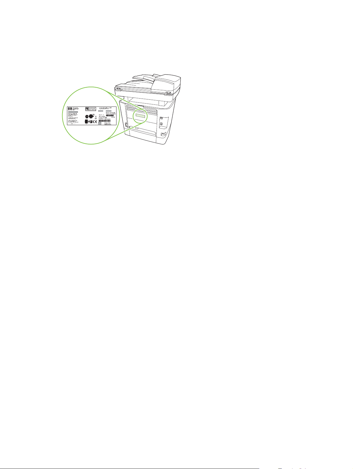
Serial number and model number location
The serial number and product model number label is on the rear output bin door at the back of the
product.
8 Chapter 1 Product information ENWW
Page 27

Software description
Supported operating systems
The product supports the following operating systems:
Full software installation
Windows XP (32-bit and 64-bit)
●
Windows Vista (32-bit and 64-bit)
●
Mac OS X v10.3, v10.4, and later
●
NOTE: For Mac OS X v10.4 and later, PPC and Intel Core Processor Macs are supported.
Supported printer drivers
The following printer drivers are provided. If the printer driver you want is not on the product CD or is
not available on
and request a driver for the product.
NOTE: The most recent drivers are available at www.hp.com. Depending on the configuration of
Windows-based computers, the installation program for the product software automatically checks the
computer for Internet access to obtain the latest drivers.
Table 1-2 Supported printer drivers
Operating system1Fax driver PCL 6 printer
www.hp.com, contact the manufacturer or distributor of the program that you are using,
Print and scan driver
Windows 98
●
Windows 2000
●
Windows 2003 Server (32-bit and
●
64-bit)
driver
PCL 5 printer
driver
Printer driver only
Linux (Web only)
●
UNIX model scripts (Web only)
●
PS printer driver PPD2 printer
driver
Microsoft Windows 98
Microsoft Millennium
Edition (Me)
Windows 2000
Windows XP
Windows Server 2003
Mac OS X v10.3,
v10.4, and later
1
Not all product features are available from all drivers or operating systems. See the context-sensitive help in the printer driver
for available features.
2
A Macintosh printer driver and the necessary PostScript (PS) Printer Description Files (PPDs) are included with the product.
X
X
XXX
X
X
X
X
X
Software included with the product
There are several options for completing a recommended installation. Easy Install will complete the
installation with default settings. Advanced Install allows you to select custom settings and choose the
components that are installed.
X
X
X
X
X
X
X
X
X
X
ENWW Software description 9
Page 28

Recommended installation for Windows
HP drivers
●
PCL 6 printer driver
◦
Scan driver
◦
HP MFP software
●
HP ToolboxFX
◦
HP LaserJet Scan program
◦
HP Send Fax program and driver
◦
HP Fax Setup Wizard
◦
Uninstall program
◦
HP Update program
●
HP Customer Participation Program
●
Shop for HP Supplies program
●
Other programs
●
Readiris OCR (not installed with other software; separate installation is required)
◦
Express installation (USB or network)
The following software is included with an Express installation:
PCL 6 printer driver
●
HP LaserJet Scan program and driver
●
NOTE: Express installation supports faxing by using the control panel.
NOTE: PCL 5 and HP postscript level 3 emulation drivers can be installed using the Microsoft Add
Printer wizard.
Macintosh software
HP Product Setup Assistant
●
HP Device Configuration
●
HP Uninstaller
●
HP LaserJet software
●
HP Scan
◦
HP Director
◦
Fax program
◦
10 Chapter 1 Product information ENWW
Page 29

Scan to e-mail program
◦
HP Photosmart
◦
ENWW Software description 11
Page 30

Software for Windows
When you install the software for Windows, you can directly connect the product to a computer by using
a USB cable, or you can connect the product to a network by using the internal print server. See the
getting started guide for installation instructions, and see the Readme file for the latest software
information.
HP ToolboxFX
Perform a typical installation in order to use HP ToolboxFX.
HP ToolboxFX provides links to product status information and Help information, such as the user guide,
and tools for product problem-solving. See
Embedded Web server (EWS)
The EWS is a Web-based interface that provides simple access to product status and configurations,
including network configurations and Smart Printing Supplies (SPS) functionality.
You can gain access to the EWS through the network connection to the product. Type the product IP
address in a Web browser to open the product EWS home page in the browser. From the home page,
you can use the tabs and left navigation menu to check the status of the product, configure the product,
or check the status of the supplies.
The following are supported browsers:
HP ToolboxFX on page 58.
Internet Explorer 5.0 or later
●
Netscape Navigator 4.75 or later
●
Opera 6.05 or later
●
Safari 1.2 or later
●
12 Chapter 1 Product information ENWW
Page 31

Software for Macintosh
For Mac OS X v10.3, v10.4, and later, use Print Center to print.
NOTE: For Macintosh computers, HP ToolboxFX is not supported.
HP Director
HP Director is a software program for working with documents. When the document is loaded into the
ADF and the computer is connected directly to the product, HP Director appears on the computer screen
to initiate faxing, scanning, or changing settings on the product through Macintosh Configure Device.
Also included is the HP product Setup Assistant, which sets up the fax and print queues.
Macintosh Configure Device (Mac OS X v10.3, v10.4, and later)
Macintosh Configure Device is a Web-based program that provides access to information about the
product (or example, information about supplies status and product settings). Use Macintosh Configure
Device to monitor and manage the product from the computer.
NOTE: You must perform a complete software installation to use Macintosh Configure Device.
Check the product status and print information pages.
●
Check and change product settings.
●
Check default print settings.
●
Check and change fax settings, including IP configuration, Advanced, mDNS, SNMP, network
●
configuration, and fax reports.
You can view Macintosh Configure Device when the product is directly connected to a computer or when
it is connected to the network.
NOTE: You do not have to have Internet access to open and use Macintosh Configure Device.
To view Macintosh Configure Device when the product is connected to the computer
1. Open HP Director by clicking the HP Director icon in the dock.
2. In HP Director, click Settings.
3. Select Configure Device to open the Macintosh Configure Device home page in a browser.
To view Macintosh Configure Device when the product is connected to the network
1. Open one of the following browsers:
Internet Explorer 5.0 or later
●
Netscape Navigator 4.75 or later
●
Opera 6.05 or later
●
Safari 1.2 or later
●
2. Type the IP address of the product into the Web browser to open the Macintosh Configure Device
home page.
ENWW Software for Macintosh 13
Page 32

PDEs (Mac OS X v10.3, v10.4, and later)
PDEs are code plug-ins that provide access to product features, such as information about the number
of copies, two-sided printing, and quality settings. An installation program for the PDEs and other
software is provided on the product CD for Macintosh.
14 Chapter 1 Product information ENWW
Page 33

Uninstall software
Windows
Use the Add or Remove Programs method in Windows to remove the product software. This method
does not require you to have the software CD.
1. Click Start, point to Settings, and then click Control Panel.
NOTE: In Windows XP, click Start, and then click Control panel.
2. Double-click Add or Remove Programs.
3. Scroll through the list of software programs and click HP LaserJet M2727.
4. Click Remove.
Macintosh
To remove the software, drag the PPD files to the trash can.
ENWW Uninstall software 15
Page 34

Media specifications
Supported paper and print media sizes
NOTE: See the user guide for information about using media correctly.
This product supports a number of paper sizes, and it adapts to various media.
NOTE: To obtain best print results, select the appropriate paper size and type in the print driver before
2
printing. Use conventional 75 to 90 g/m
(20 to 24 lb) photocopy paper. Verify that the paper is of good
quality and is free of cuts, nicks, tears, spots, loose particles, dust, wrinkles, curls, and bent edges.
Table 1-3 Supported paper and print media sizes
Size Dimensions Tray 1 Trays 2 and 3
Letter 216 x 279 mm (8.5 x 11 inches)
Legal 216 x 356 mm (8.5 x 14 inches)
A4 210 x 297 mm (8.27 x 11.69 inches)
Executive 184 x 267 mm (7.24 x 10.51 inches)
A3 297 x 420 mm (11.69 x 16.54 inches)
A5 148 x 210 mm (5.83 x 8.27 inches)
A6 105 x 148 mm (4.13 x 5.83 inches)
B5 (JIS) 182 x 257 mm (7.17 x 10.12 inches)
16k 197 x 273 mm (7.75 x 10.75 inches)
16k 195 x 270 mm (7.7 x 10.6 inches)
16k 184 x 260 mm (7.25 x 10.25 inches)
8.5 x 13 216 x 330 mm (8.5 x 13 inches)
1
4 x 6
1
5 x 8
10 x 15 cm
Custom Tray 1: Minimum—76 x127 mm (3 x 5 inches);
1
These sizes are supported as custom sizes.
1
107 x 152 mm (4 x 6 inches)
127 x 203 mm (5 x 8 inches)
100 x 150 mm (3.9 x 5.9 inches)
Maximum—216 x 356 mm (8.5 x 14 inches)
Trays 2 and 3: Minimum—148 x 210 mm (5.8 x
8.3 inches); Maximum—216 x 356 mm (8.5 x
14 inches)
16 Chapter 1 Product information ENWW
Page 35

Table 1-4 Supported envelopes and postcards
Size Dimensions Tray 1 Trays 2 and 3
Envelope #10 105 x 241 mm (4.13 x 9.49 inches) Not supported.
Envelope DL 110 x 220 mm (4.33 x 8.66 inches) Not supported.
Envelope C5 162 x 229 mm (6.93 x 9.84 inches) Not supported.
Envelope B5 176 x 250 mm (6.7 x 9.8 inches) Not supported.
Envelope Monarch 98 x 191 mm (3.9 x 7.5 inches) Not supported.
Postcard 100 x 148 mm (3.94 x 5.83 inches) Not supported.
Double postcard 148 x 200 mm (5.83 x 7.87 inches) Not supported.
Table 1-5 ADF
Media Dimensions Weight Capacity
Minimum-size 127 x 127 mm (5 x 5 inches)
Maximum-size 216 x 381 mm (8.5 x
15 inches)
NOTE: When faxing, copying, or scanning using the product, use the flatbed scanner if the original is
fragile, thin, thick, too small for the ADF, or a photograph. Also use the flatbed scanner for the fit-topage copying feature. The flatbed scanner provides the best fax, copy, and scan resolution.
Media to avoid
The product can handle many types of media. Using media that is outside the specifications degrades
print quality and increases the chance of jams occurring.
Do not use media that is too rough.
●
Do not use media that contains cutouts or perforations other than standard 3-hole punched paper.
●
Do not use multipart forms.
●
Do not use paper that contains a watermark if you are printing solid patterns.
●
Media that can damage the product
In rare circumstances, media can damage the product. Avoid the following types of media to prevent
possible damage:
60 to 90 gm2 (16 to 24 lb)
50 sheets
Do not use media with staples attached.
●
Do not use transparencies designed for inkjet printers or other low-temperature printers. Use only
●
transparencies that are specified for use with HP LaserJet printers.
Do not use photo paper intended for inkjet printers.
●
ENWW Media specifications 17
Page 36

Do not use paper that is embossed or coated and is not designed for the temperature of the image-
●
fuser. Select media that can tolerate temperatures of 200°C (392°F) for 0.1 second.
HP manufactures a media that is designed for the product.
Do not use letterhead paper that was produced with low-temperature dyes or thermography.
●
Preprinted forms or letterhead must use inks that can tolerate temperatures of 200°C (392°F) for
0.1 second.
Do not use any media that produces emissions, or that melts, offsets, or discolors when exposed
●
to 200°C (392°F) for 0.1 second.
To order HP LaserJet printing supplies, go to
www.hp.com/go/ljsupplies worldwide.
www.hp.com/go/ljsupplies in the U.S., or go to
18 Chapter 1 Product information ENWW
Page 37

2 Installation
Operating environment
●
Unpack the product
●
Install input devices
●
Install the control-panel faceplate
●
Load paper and print media
●
Install memory DIMMs
●
ENWW 19
Page 38

Operating environment
Place the product on a sturdy, level surface in a well-ventilated area. Make sure that the air vents are
not blocked and that the product is installed away from direct sunlight, open flames, and ammonia fumes.
Store or install the product in an area that meets the following requirements:
Temperature (printer; operating) 15
●
Temperature (printer; storage) -20
●
Humidity (printer; operating) 10% to 80% relative humidity (no condensation)
●
Humidity (printer; storage) 10% to 90% relative humidity (no condensation)
●
Temperature (toner cartridge; storage) -20
●
Humidity (toner cartridge; storage) 10% to 90% relative humidity (no condensation)
●
o
to 32.5oC (59o to 90.5oF)
o
to 60oC (-4o to 140oF)
o
to 40o C (-4 to 104o F)
Figure 2-1 Operating environment
7
00 mm (27.
5 inc
hes)
595 m
m
(
23.5 in
31
(
m
0 m
79
c
he
s)
s)
e
h
c
in
0
.
20 Chapter 2 Installation ENWW
Page 39

Minimum system requirements
Windows OS (Win 98, Win 2000, 2003 Server, Millennium Edition (Me), XP, or Vista)
●
or
Mac OS X v10.3 and later
128 MB RAM for Windows operating systems
●
32 MB RAM for Macintosh operating systems
●
250 MB hard-disk space (full installation)
●
CD-ROM drive
●
USB port
●
ENWW Operating environment 21
Page 40

Unpack the product
The following components are included in the box.
NOTE: The USB and network cables are not included.
Figure 2-2 HP LaserJet M2727 MFP package contents
1
3
4
6
7
5
8
9
2
Item Description
1 Automatic document feeder (ADF) input tray
2 HP LaserJet M2727 MFP
3 Power cord
4 Fax cord
5 Print cartridge
6 Start guide and support flyer
7 CD-ROMs (software and online user guide)
8 250-sheet media input tray (optional tray 3, standard on the HP LaserJet M2727nfs only)
9 Control-panel faceplate (if not already installed)
Installing the supplies (for example, the print cartridge) is similar to replacing them. See Manage supplies
on page 34 for more information about installing supplies.
22 Chapter 2 Installation ENWW
Page 41

Install input devices
ADF input tray
1. Open the ADF cover.
2. Align the two tabs on the input tray with the grooves in the ADF.
3. Slide the tray into the grooves until the tray snaps into place.
4. Close the ADF cover.
Figure 2-3 Install the ADF input tray
ENWW Install input devices 23
Page 42

250-sheet input tray (tray 3)
CAUTION: Always install the 250-sheet tray (tray 3) in the location where the product will remain. The
assembled combination is heavy, and cannot be easily moved.
1. Place the 250-sheet feeder (tray 3) on a sturdy, level surface.
2. Using the alignment pins at the corners of the tray as a guide place the product on top of the tray.
3. Make sure that the right-rear connector (callout 1) connects with the product.
Figure 2-4 Install the 250-sheet input tray
1
24 Chapter 2 Installation ENWW
Page 43

Install the control-panel faceplate
NOTE: The control-panel faceplate might already be installed.
1. Lift the scanner cover.
2. Align the control-panel faceplate with the product.
3. Beginning in the center of the faceplate and working outward, press the faceplate until it snaps into
place.
Figure 2-5 Install the control-panel faceplate
3
2
1
2
3
ENWW Install the control-panel faceplate 25
Page 44

Load paper and print media
Load documents to fax, copy, or scan
NOTE: For the best-quality scans, use the flatbed scanner.
To load originals onto the flatbed scanner
1. Make sure that the automatic document feeder (ADF) contains no media.
2. Lift the scanner cover.
3. Place the original document face-down on the flatbed scanner glass with the upper-left corner of
the document at the lower-right corner of the glass.
Figure 2-6 Load a document onto the flatbed scanner
4. Gently close the scanner cover.
The document is ready to be faxed/copied/scanned.
26 Chapter 2 Installation ENWW
Page 45

To load originals into the ADF
NOTE: The ADF capacity for the product is up to 50 sheets of 75 g/m2 (20 lb) media.
1. Insert the stack of originals into the ADF input tray top-edge-first, with the media stack face-up and
the first page to be copied on the top of the stack. Slide the stack into the ADF until it does not
move any farther.
Figure 2-7 Load documents into the ADF (1 of 2)
2. Adjust the media guides until they are snug against the stack.
Figure 2-8 Load documents into the ADF (2 of 2)
3. The document is ready to be faxed, copied, or scanned.
Tray 1
Tray 1 is accessed from the front of the product. The product prints from tray 1 before attempting to print
from other trays.
ENWW Load paper and print media 27
Page 46

Tray 1 holds up to 50 sheets of 75 g/m2 (20 lb) media or five envelopes, ten transparencies, or ten cards.
You can use tray 1 to print the first page on media different from the remainder of the document.
Media guides ensure that the media is correctly fed into the product and that the print is not skewed
(crooked on the media). When loading media, adjust the media guides to match the width of the media
that you are using.
Tray 2 or 3
Tray 2 and optional tray 3 hold up to 250 pages of 75 g/m2 (20 lb) paper, or fewer pages of heavier
media (25 mm (0.9 in) or less stack height). Load media with the top forward and the side to be printed
on facing down.
Media guides ensure that the media feeds correctly into the product and that the print is not skewed.
Tray 2 has side and rear media guides. When loading media, adjust the media guides to match the
length and width of the media that you are using.
28 Chapter 2 Installation ENWW
Page 47

NOTE: When you add new media, make sure that you remove all of the media from the input tray and
straighten the stack of new media. Do not fan the media. This reduces jams by preventing multiple
sheets of media from feeding through the product at one time.
Configure trays
When using one of the trays for a specific size of paper, you can set the default size for the tray in
HP ToolboxFX or from the control panel. In HP ToolboxFX, select Paper handling, and then select the
size for the tray you want to set. When you select that size of paper for a print job in the print dialog, the
product automatically selects that tray for printing.
To set the default paper size or type from the control panel, complete the following steps:
1. On the product control panel, press Setup.
2. Use the arrow buttons to select System setup, and then press OK.
3. Use the arrow keys to select Paper setup, and then press OK.
4. Use the arrow keys to select the tray to be configured, and then press OK.
5. Use the arrow keys to select either Paper type or Paper size, and then press OK.
6. Use the arrow keys to select a default type or size for the tray, and then press OK.
Change tray selection
The product is set to automatically pull media from trays that contain media. The product always pulls
media from tray 1 if you insert media into tray 1. If there is no media in tray 1, the product attempts to
pull media from tray 3, if installed, and then from tray 2.
You can specify which tray you want to use by changing the tray selection. Auto select, Tray 1, Tray
2, and Tray 3 are available settings. Auto select will pull media from the first available tray with the
appropriate matching media loaded.
NOTE: Tray 3 is only available if a tray 3 is installed.
Change the tray selection for the current job
1. On the product control panel, press Tray Select.
2. Use the arrow buttons to select the input tray that you want to use.
3. Press Start Copy to save the selection and immediately start the copy job, or press OK to save the
selection without starting the job.
Change the default tray selection
1. On the product control panel, press Setup.
2. Use the arrow buttons to select Copy setup, and then press OK.
3. Use the arrow buttons to select Def. Tray Select, and then press OK.
4. Use the arrow buttons to select a tray setting, and then press OK.
ENWW Load paper and print media 29
Page 48

Install memory DIMMs
Information
The product comes with 64 MB of RAM and can be upgraded to 320 MB via the DIMM slot, which is
accessible from the left side of the product.
Install a memory DIMM
CAUTION: Handling a DIMM without wearing a grounded, antistatic device might damage the DIMM.
Touch any metal part of the product or other grounded metal before touching the DIMM.
1. Use the power switch to turn off the product, and then unplug all of the cables and cords connected
to the product.
2. Open the DIMM door.
3. Remove the DIMM from the antistatic bag it came in, grasping the DIMM on the top edge.
30 Chapter 2 Installation ENWW
Page 49

4. With the gold contacts facing upward, insert the DIMM in the DIMM seat and press the DIMM body
in until the metal retaining pins click.
5. Close the DIMM door.
6. Reconnect all cables and cords, and then use the power switch to turn on the product.
7. Print a configuration page, and then verify that the Memory section shows the new memory amount.
Product information pages and reports on page 237.
See
ENWW Install memory DIMMs 31
Page 50

32 Chapter 2 Installation ENWW
Page 51

3 Maintenance
Manage supplies
●
Clean the product
●
Manage the product
●
ENWW 33
Page 52

Manage supplies
This section describes replacing the print cartridge, staple cassette, tray 2 pickup roller, and the tray 2
and optional tray 3 separation pad. For information about replacing the ADF pickup-roller assembly, see
Replace the ADF pickup-roller assembly on page 110.
Inspect any parts that wear when servicing the product. Replace them as needed, based on failure or
wear rather than usage.
The following table lists approximate schedules for replacing consumables.
Life expectancies of supplies and the product
Item Capacity
HP LaserJet M2727 MFP Series Recommended maximum of 3,000 pages per month
Print cartridge 3,500 pages1 (standard)
7,000 pages
Staple cassette 1,500 staples
1
The estimated print cartridge life is based on using letter- or A4-sized media with an average of 5% toner coverage and a
medium density setting. Print cartridge life can be extended by using draft-mode settings to conserve toner.
1
(high-capacity)
Order supplies
NOTE: To locate part numbers for supplies, see Accessories and ordering information
on page 247.
To order supplies, go to one of the following Web sites.
North America:
●
Europe and Middle East:
●
Asia Pacific countries/regions:
●
Latin America:
●
www.hp.com/go/orders/supplies-na
www.hp.com/go/orders/supplies-emea
www.hp.com/go/orders/supplies-ap
www.hp.com/go/orders/supplies-la
34 Chapter 3 Maintenance ENWW
Page 53

Store print cartridges
Follow these guidelines for storing print cartridges:
Do not remove the print cartridge from its package until you are ready to use it.
●
CAUTION: To prevent damage, do not expose the print cartridge to light for more than a few
minutes.
Make sure that you store print cartridges in accordance with the environmental operating and
●
storage specifications in this manual. See
Store the print cartridges in a horizontal position.
●
Store the print cartridges in a dark, dry location away from heat and magnetic sources.
●
Replace and recycle supplies
Visit www.hp.com/go/environment or www.hp.com/hpinf/community/environment/productinfo/saftey for
information about the following environmental topics:
Product environmental profile sheet for this and many related HP products
●
Hewlett Packard's commitment to the environment
●
Hewlett-Packard's environmental management system
●
Environmental specifications on page 325.
Hewlett Packard's end-of-life product return and recycling program
●
Material safety data sheets (MSDSs), which are also available at:
●
information about supplies that contain chemical substances, such as toner.
It's easy to return and recycle your empty HP LaserJet print cartridges—free of charge—with HP Planet
Partners. HP is committed to providing inventive, high-quality products and services that are
environmentally sound, from product design and manufacturing to distribution, operation, and recycling
processes. We ensure that returned HP LaserJet print cartridges are recycled properly, processing them
to recover valuable plastics and metals for new products and diverting millions of tons of waste from
landfills. Because this cartridge is being recycled and used in new materials, it will not be returned to
you. Empty HP LaserJet print cartridges are recycled responsibly when you participate in the HP Planet
Partners program. Thank you for being environmentally responsible!
In many countries/regions, this product's printing supplies (for example, the print cartridge) can be
returned to HP through the HP Printing Supplies Returns and Recycling Program. An easy-to-use and
free take-back program is available in more than 35 countries/regions. Multi-lingual program information
and instructions are included in every new HP LaserJet print cartridge and supplies package.
HP Printing Supplies Returns and Recycling Program information
Since 1992, HP has offered HP LaserJet supplies return and recycling free of charge. In 2004, HP Planet
Partners for LaserJet Supplies was available in 85% of the world market where HP LaserJet supplies
are sold. Postage-paid and pre-addressed labels are included within the instruction guide in most HP
LaserJet print cartridge boxes. Labels and bulk boxes are also available through the Web site
www.hp.com/go/recycle.
www.hp.com/go/msds, contain
Use the label to return empty, original HP LaserJet print cartridges only. Please do not use this label for
non-HP cartridges, refilled or remanufactured cartridges, or warranty returns. Printing supplies or other
objects that are inadvertently sent to the HP Planet Partners program cannot be returned.
ENWW Manage supplies 35
Page 54

More than 10 million HP LaserJet print cartridges were recycled globally in 2004 through the HP Planet
Partners supplies recycling program. This record number represents 26 million pounds of print cartridge
materials diverted from landfills. In 2004, HP recycled an average of 59% of the print cartridge by weight
consisting primarily of plastic and metals. Plastics and metals are used to make new products such as
HP products, plastic trays and spools. The remaining materials are disposed of in an environmentally
responsible manner.
U.S. returns
For a more environmentally responsible return of used cartridges and supplies, HP encourages the use
of bulk returns. Simply bundle two or more cartridges together and use the single, pre-paid, preaddressed UPS label that is supplied in the package. For more information in the U.S., call
1-800-340-2445 or visit the HP Web site at
www.hp.com/go/recycle.
Non-U.S. returns
Non-U.S. customers should visit the
www.hp.com/go/recycle Web site for further information regarding
availability of the HP Printing Supplies Returns and Recycling Program.
Paper
This product is capable of using recycled papers, when the paper meets the guidelines outlined in the
HP LaserJet Printer Family Print Media Guide, which you can view on the Web at
www.hp.com/support/
ljpaperguide. This product is suitable for the use of recycled paper according to EN12281:2002.
Material restrictions
This HP product contains a battery and contains mercury in the fluorescent lamp or scanner that might
require special handling at end-of-life.
Type: Lithium carbon monofluoride (solid button cell)
Weight: Approximately .1 gram
Location: On formatter PC board (one battery per product)
User removable: No
36 Chapter 3 Maintenance ENWW
Page 55

Replace print cartridge
1. Open the print-cartridge door.
2. Grasp the handle on the print cartridge and then pull the cartridge straight out to remove it. See
the recycling information inside the print cartridge box.
3. Remove the new print cartridge from its packaging, remove the orange cover from the print
cartridge, and then pull the orange tab straight out to remove the sealing tape.
4. Insert the cartridge into the product until it is firmly in place.
ENWW Manage supplies 37
Page 56

5. Close the print-cartridge door.
CAUTION: If toner gets on any clothing, wipe it off with a dry cloth and wash the clothing in cold water.
Hot water sets toner into the fabric.
38 Chapter 3 Maintenance ENWW
Page 57

Load staples
Each staple cassette holds 1,500 unformed staples.
1. Open the stapler door.
NOTE: Opening the stapler door disables the stapler.
Instructions and replacement staples part numbers are listed on the stapler door.
2. If you are replacing a staple cassette (for example, if the staple cassette has run out of staples),
remove the staple cassette from the product.
3. Insert a new staple cassette into the opening inside the stapler door.
4. Close the stapler door.
ENWW Manage supplies 39
Page 58

Replace the tray 2 pickup roller
CAUTION: Failure to correctly complete this procedure might cause damage to the product.
1. Perform the following tasks before beginning this procedure:
Turn off the product and unplug the power cord from the electrical outlet.
●
Open the print-cartridge door and remove the print cartridge.
●
Remove the tray 2 cassette.
●
Lift the product off of tray 3, if that tray is installed.
●
2. Place the product on its back on the work surface, with the front facing up.
WARNING! When you move the product into this position, the scanner cover can open suddenly
and be damaged. You must support the scanner cover to keep it from opening.
Figure 3-1 Replace the tray 2 pickup roller (1 of 7)
40 Chapter 3 Maintenance ENWW
Page 59

3. Reach into the area that you exposed when you removed tray 2. Pull the white tabs outward, and
then rotate the roller-retaining collars up.
TIP: Push down on the green tab to release and lower the duplex assembly to expose more of
the roller.
Figure 3-2 Replace the tray 2 pickup roller (2 of 7)
4. With the tab on the collar aligned with the slot in the plastic bracket, slide the collar to the right.
Leave the collar in this position for the remainder of this procedure.
Figure 3-3 Replace the tray 2 pickup roller (3 of 7)
ENWW Manage supplies 41
Page 60

5. Remove the pickup roller.
Figure 3-4 Replace the tray 2 pickup roller (4 of 7)
6. Insert the left side of the replacement pickup-roller shaft into the left slot (callout 1), and then insert
the right side shaft (the side with the notch) into the right slot (callout 2).
Figure 3-5 Replace the tray 2 pickup roller (5 of 7)
7. Rotate the roller shaft until the notch engages with the drive shaft and clicks into place.
42 Chapter 3 Maintenance ENWW
Page 61

8. Place the left retaining collar over the end of the roller shaft, align the tab on the collar with the slot
in the plastic bracket, and then slide the collar toward the pickup roller.
Figure 3-6 Replace the tray 2 pickup roller (6 of 7)
9. With the tab on the right collar aligned with the slot on the plastic bracket, slide the collar towards
the pickup roller. Rotate the right and left retaining collars down into the locked position.
Figure 3-7 Replace the tray 2 pickup roller (7 of 7)
10. Push up on the duplex assembly until it locks into place. Place the product upright on the work
surface with the top of the product facing up.
ENWW Manage supplies 43
Page 62

WARNING! When you move the product into this position, the scanner cover can open suddenly
and be damaged. You must support the scanner cover to keep it from opening.
11. Perform the following tasks after completing this procedure.
Replace the product on tray 3, if that tray was installed.
●
Replace the tray 2 cassette.
●
Open the print-cartridge door and install the print cartridge.
●
Plug the power cord into an electrical outlet, and turn on the product.
●
44 Chapter 3 Maintenance ENWW
Page 63

Replace the tray 2 and optional tray 3 separation pad
1. Remove tray 2 or tray 3.
Figure 3-8 Replace the tray 2 or tray 3 separation pad (1 of 6)
2. Locate the separation pad.
Figure 3-9 Replace the tray 2 or tray 3 separation pad (2 of 6)
ENWW Manage supplies 45
Page 64

3. Remove two screws.
Figure 3-10 Replace the tray 2 or tray 3 separation pad (3 of 6)
4. Remove the separation pad.
CAUTION: Before you remove the separation pad, take note of how it is positioned in the tray.
Figure 3-11 Replace the tray 2 or tray 3 separation pad (4 of 6)
46 Chapter 3 Maintenance ENWW
Page 65

5. Install the replacement separation pad.
Figure 3-12 Replace the tray 2 or tray 3 separation pad (5 of 6)
6. Replace the two screws, and then return the tray to the product.
Figure 3-13 Replace the tray 2 or tray 3 separation pad (6 of 6)
ENWW Manage supplies 47
Page 66

HP policy on non-HP supplies
Hewlett-Packard Company cannot recommend the use of non-HP supplies, either new or
remanufactured. Because they are not HP products, HP cannot influence their design or control their
quality. Service or repairs required as a result of using a non-HP supply will not be covered under the
warranty.
When you insert a supply into the product, the product will inform you if the supply is not a genuine
HP supply. If you insert a genuine HP supply that has reached the low state from another HP device,
the product identifies the supply as non-HP. Simply return the supply to the original device to reactivate
the HP features and functionality.
Reset the product for non-HP supplies
When you install a non-HP print cartridge, Unauthorized appears on the control-panel display. In order
to print with this supply, you must press OK when you install this non-HP supply.
CAUTION: The product will not stop printing when this type of supply is empty. Damage to the product
could occur if the product prints with an empty non-HP print cartridge. See
warranty statement on page 319 and Print cartridge limited warranty statement on page 321.
HP fraud hotline
Call the HP fraud hotline if the product or HP ToolboxFX indicates that the print cartridge is not an
HP print cartridge and you think that it is genuine. HP will help determine if the product is genuine and
take steps to resolve the problem.
Hewlett-Packard limited
The print cartridge might not be a genuine HP product if you notice the following issues:
You are experiencing a large number of problems with the print cartridge.
●
The print cartridge does not look like it usually does (for example, the pull tab or the box is different).
●
In the United States, call toll-free: 1-877-219-3183.
Outside the United States, you can call collect. Dial the operator and ask to place a collect call to this
telephone number: 1-770-263-4745. If you do not speak English, a representative at the HP fraud hotline
who speaks your language will assist you. Or, if someone who speaks your language is not available,
a language line interpreter will connect approximately one minute after the beginning of the call. The
language line interpreter is a service that will translate between you and the representative for the HP
fraud hotline.
48 Chapter 3 Maintenance ENWW
Page 67

Clean the product
Clean the exterior
Use a soft, damp, lint-free cloth to wipe dust, smudges, and stains off of the exterior of the product.
Clean the flatbed scanner glass
Dirty glass, from fingerprints, smudges, hair, and so on, slows down performance and affects the
accuracy of special features such as fit-to-page and copy.
NOTE: If streaks or other defects appear only on copies produced from the ADF, clean the ADF
scanner glass (step 3). It is not necessary to clean the flatbed scanner glass.
1. Turn off the product, unplug the power cord from the electrical outlet, and raise the scanner cover.
2. Clean the glass by using a soft cloth or sponge that has been moistened with nonabrasive glass
cleaner.
CAUTION: Do not use abrasives, acetone, benzene, ammonia, ethyl alcohol, or carbon
tetrachloride on any part of the product, as they can damage the product. Do not place liquids
directly on the glass. They might seep under it and damage the product.
Figure 3-14 Clean the scanner glass (1 of 2)
ENWW Clean the product 49
Page 68

3. Clean the ADF scanner glass by using a soft cloth or sponge that has been moistened with
nonabrasive glass cleaner.
Figure 3-15 Clean the scanner glass (2 of 2)
50 Chapter 3 Maintenance ENWW
Page 69

Clean the scanner-cover backing
1. Turn off the product, unplug the power cord from the electrical outlet, and raise the scanner cover.
2. Clean the white scanner-cover backing by using a soft cloth or sponge that has been moistened
with mild soap and warm water. Also, clean the ADF scanner glass (callout 1) next to the flatbed
scanner glass.
Figure 3-16 Clean the scanner-cover backing
1
3. Wash the backing gently to loosen debris; do not scrub the backing.
4. Dry the backing by using a chamois or soft cloth.
CAUTION: Do not use paper-based wipes because they might scratch the backing.
5. If this does not clean the backing well enough, repeat the previous steps and use isopropyl alcohol
to dampen the cloth or sponge, and then wipe the backing thoroughly with a damp cloth to remove
any residual alcohol.
ENWW Clean the product 51
Page 70

Clean the tray 2 pickup roller
1. Perform the removal steps from Replace the tray 2 pickup roller on page 40.
2. Gently wipe the roller with a lint-free cloth moistened with water.
Figure 3-17 Clean the tray 2 pickup roller (1 of 6)
3. Use a dry lint-free cloth to wipe the roller and remove loosened dirt.
Figure 3-18 Clean the tray 2 pickup roller (2 of 6)
4. Allow the roller to dry completely before you reinstall it.
Figure 3-19 Clean the tray 2 pickup roller (3 of 6)
52 Chapter 3 Maintenance ENWW
Page 71

5. Insert the left side of the pickup-roller shaft into the left slot (callout 1), and then insert the right side
of the shaft (the side with the notch) into the right slot (callout 2).
Figure 3-20 Clean the tray 2 pickup roller (4 of 6)
6. Rotate the roller shaft until the notch engages with the drive shaft and clicks into place.
7. Place the left retaining collar over the end of the roller shaft, align the tab on the collar with the slot
in the plastic bracket, and then slide the collar toward the pickup roller.
Figure 3-21 Clean the tray 2 pickup roller (5 of 6)
ENWW Clean the product 53
Page 72

8. With the tab on the right collar aligned with the slot on the plastic bracket, slide the collar towards
the pickup roller. Rotate the right and left retaining collars down into the locked position.
Figure 3-22 Clean the tray 2 pickup roller (6 of 6)
9. Push up on the duplex assembly until it locks into place, and then place the product upright on the
work surface with the top of the product facing up.
WARNING! When you move the product into this position, the scanner cover can open suddenly
and be damaged. You must support the scanner cover to keep it from opening.
10. Perform the following tasks after completing this procedure.
Replace the product on tray 3, if that tray was installed.
●
Replace the tray 2 cassette.
●
Open the print-cartridge door and install the print cartridge.
●
Plug the power cord into an electrical outlet, and turn on the product.
●
54 Chapter 3 Maintenance ENWW
Page 73

Clean the ADF pickup-roller assembly
1. Turn off the product and unplug the power cord.
Figure 3-23 Clean the ADF pickup-roller assembly (1 of 5)
2. Open the ADF cover.
Figure 3-24 Clean the ADF pickup-roller assembly (2 of 5)
3. Rotate the assembly upward. Wipe it clean and rotate the rollers until the assembly is clean.
Figure 3-25 Clean the ADF pickup-roller assembly (3 of 5)
ENWW Clean the product 55
Page 74

4. Lower the green lever and the roller assembly and close the ADF cover.
Figure 3-26 Clean the ADF pickup-roller assembly (4 of 5)
5. Plug in the product, and then turn it on.
Figure 3-27 Clean the ADF pickup-roller assembly (5 of 5)
Clean the paper path
During the printing process, paper, toner, and dust particles can accumulate inside the product. Over
time, this buildup can cause print-quality problems such as toner specks or smearing. This product has
a cleaning mode that can correct and prevent these types of problems.
Specks Smearing
56 Chapter 3 Maintenance ENWW
Page 75

Clean the paper path from HP ToolboxFX
Use HP ToolboxFX to clean the paper path. This is the recommended cleaning method. If you do not
have access to HP ToolboxFX, use the method in
on page 57.
1. Make sure that the product is turned on and in the Ready state, and that media is loaded in tray 1
or tray 2.
2. Open HP ToolboxFX, click the product, and then click the System Settings tab.
3. Click the Service tab, and then click Start.
A page feeds through the product slowly. Discard the page when the process is completed.
Clean the paper path from the product control panel
Clean the paper path from the product control panel
If you do not have access to HP ToolboxFX, you can print and use a cleaning page from the product
control panel.
1. Press Setup.
2. Use the arrow buttons to select the Service menu, and then press OK.
3. Use the arrow buttons to select Cleaning mode, and then press OK.
4. Load plain letter or A4 paper when you are prompted.
5. Press OK again to confirm and begin the cleaning process.
A page feeds through the product slowly. Discard the page when the process is completed.
ENWW Clean the product 57
Page 76

Manage the product
HP ToolboxFX
The HP ToolboxFX is a Web-based program that you can use to complete the following tasks:
Check the product status.
●
Configure the product settings.
●
View problem-solving information.
●
View online documentation.
●
You can view the HP ToolboxFX when the product is directly connected to your computer or when it is
connected to the network. You must perform a typical software installation to use HP ToolboxFX.
NOTE: The HP ToolboxFX is not supported for Windows 98 SE or Macintosh operating systems. To
use the HP ToolboxFX, the TCP/IP protocol must be installed on the computer. You do not have to have
Internet access to open and use the HP ToolboxFX.
View the HP ToolboxFX
Open the HP ToolboxFX in one of these ways:
In the Windows system tray or on the desktop, double-click the HP ToolboxFX icon.
●
Status
On the Windows Start menu, click Programs (or All Programs in Windows XP), click HP, click
●
HP LaserJet M2727, and then click HP ToolboxFX.
The HP ToolboxFX software contains the following tabs, and the information about each tab is on the
specified page:
Status on page 58
●
Alerts on page 59
●
Fax on page 59
●
Help (Documentation) on page 62
●
System settings on page 63
●
Print settings on page 65
●
Network settings on page 66
●
The HP ToolboxFX Status tab contains links to the following main pages:
Device Status. View product status information. This page indicates product conditions such as
●
a jam or an empty tray. After you correct a problem with the product, click Refresh Status to update
the product status.
Supplies Status. View detailed supplies status, such as the estimated percentage of toner
●
remaining in the print cartridge and the number of pages that have been printed with the current
print cartridge. This page also has links to order supplies and to find recycling information.
58 Chapter 3 Maintenance ENWW
Page 77

Event log
Alerts
Device configuration. View a detailed description of the current product configuration, including
●
the amount of memory that is installed and whether optional trays are installed.
Network configuration. View a detailed description of the current network configuration, including
●
the IP address and network status.
Print Info Pages. Print the Configuration page and various other information pages that are
●
available for the product, such as the Supplies Status page and the Demo page.
Event Log. View a history of product errors. The most recent error is at the top of the list.
●
The Event log is a four-column table where the product events are logged for your reference. The log
contains codes that correspond to the error messages that appear on the product control-panel display.
The number in the Page Count column specifies the total number of pages that the product had printed
when the error occurred. The Event log also contains a brief description of the error. For more information
about error messages, see
The HP ToolboxFX Alerts tab contains links to the following main pages:
Set up Status Alerts. Set up the product to send pop-up alerts for certain events, such as low
●
toner levels.
Control-panel messages on page 169.
Set up E-mail Alerts. Set up the product to send e-mail alert messages for certain events, such
●
as low toner levels.
Set up status alerts
Use HP ToolboxFX to set up the product so that it issues pop-up alerts when certain events occur.
Events that trigger alerts include jams, low levels of toner in HP print cartridges, non-HP print cartridge
in use, empty input trays, and specific error messages.
Select the pop-up format, the tray icon format, or both for the alerts. The pop-up alerts only appear when
the product is printing from the computer on which you set up the alerts.
NOTE: You must click Apply before changes take effect.
Set up e-mail alerts
Use HP ToolboxFX to configure up to two e-mail addresses to receive alerts when certain events occur.
You can specify different events for each e-mail address. Specify the information for the e-mail server
that will send out the e-mail alert messages for the product.
NOTE: You must click Apply before changes take effect.
Fax
Use the HP ToolboxFX Fax tab to perform fax tasks from the computer. The Fax tab contains links to
the following main pages:
Fax Tasks. Perform such tasks as sending a fax or clearing the fax memory, or set the fax receive
●
mode.
Fax Phone Book. Add, edit, or delete entries in the product phone book.
●
ENWW Manage the product 59
Page 78

Fax tasks
Fax Send Log. View all of the recent faxes that have been sent from the product.
●
Fax Receive log. View all of the recent faxes that have been received by the product.
●
Fax Dat Properties. Manage the space used to store faxes on a computer. These settings apply
●
only if you have chosen to send or receive faxes remotely from the computer.
The following three options are available when receiving a fax:
Print the fax. You can select an option to have a message appear on a computer to notify you
●
when a fax is printed.
Receive the fax on your computer. You can select an option to have a message appear on a
●
computer to notify you when a fax arrives. If the fax machine is connected to multiple computers,
only one computer can be designated to receive faxes.
Forward the fax to another fax machine.
●
For more information about fax tasks, see
NOTE: You must click Apply before changes take effect.
Fax phone book
Use the HP ToolboxFX Fax phone book to add and remove individuals or groups on a speed-dial list,
import phone books from a variety of sources, and update and maintain a contact list.
To add an individual contact to a speed-dial list:
●
1. Select the check box next to the speed dial number that you want to specify.
2. Type the contact name in the Contact Name window.
3. Type the fax number in the Fax number window.
4. Click Add/Edit.
To add a group of contacts to a speed-dial list:
●
1. Select the check box next to the speed-dial number that you want to specify.
2. Click New/Edit Group.
3. Double-click a contact name from the list on the left to move it to the group list on the right, or
Fax on page 59.
select a name on the left and then click the appropriate arrow to move it to the group list on
the right. You can also use these two methods to move names from right to left.
4. When you have created a group, type a name in the Group name window, and then click
OK.
To edit an existing individual speed-dial entry:
●
1. Click anywhere on the row that contains the contact name to select it.
2. Type changes in the appropriate windows, and then click Add/Edit.
You can also make changes directly in the phone book directory list by clicking the entry and
typing your changes. Make sure that you do not have a check mark in the Select column.
60 Chapter 3 Maintenance ENWW
Page 79

To edit an existing group speed-dial entry:
●
1. Click anywhere on the row containing the group name to select it, and then click New/Edit
Group.
2. Make any required changes, and then click OK.
You can make changes to the name of the group directly in the phone book directory list by
clicking the entry and typing your changes. Make sure that you do not have a check mark in
the Select column.
To delete an entry from the speed-dial list: Select the item and then click Delete.
●
To move speed-dial entries:
●
1. Select the entry and then click Move, or you can select Move and then specify the entry in
the dialog box.
2. Select Next empty row, or specify the number of the row where you want to move the entry.
NOTE: If you specify a row that is occupied, the new entry will overwrite the existing entry.
To import contacts from a phone book that exists in Lotus Notes, Outlook, or Outlook Express:
●
1. Click Import Phone Book.
2. Select the appropriate software program, navigate to the appropriate file, and then click OK.
You can also select individual entries from the phone book instead of importing the entire
phone book.
To select all of the entries in your speed-dial list: Click the Select column heading.
●
In addition to numerical digits, the following are valid characters for fax numbers:
(
●
)
●
+
●
-
●
*
●
#
●
R
●
W
●
.
●
,
●
<space>
●
NOTE: You must click Apply before changes take effect.
ENWW Manage the product 61
Page 80

Fax send log
The HP ToolboxFX Fax send log lists all recently sent faxes and information about them, including the
date and time sent, job number, fax number, page count, and the results.
When you send a fax from a computer that is connected to the product, the fax contains a View link.
Click this link to open a new page that provides information about the fax.
Click any column heading in the Fax send log to re-sort the information in that column in ascending or
descending order.
The Results column shows the status of the fax. If the fax attempt was unsuccessful, this column
provides a description of why the fax was not sent.
NOTE: You must click Apply before changes take effect.
For more information about faxes, see Fax on page 59.
Fax receive log
The HP ToolboxFX Fax receive log provides a list of all recently received faxes and information about
them, including the date and time received, job number, fax number, page count, results, and an
abbreviated fax image.
When you receive a fax on a computer that is connected to the product, the fax contains a View link.
Click this link to open a new page that provides information about the fax.
Click on any column heading in the Fax receive log to re-sort the information in that column in ascending
or descending order.
The Results column provides the status of the fax. If the fax attempt was unsuccessful, this column
provides a description of why the fax was not received.
NOTE: You must click Apply before changes take effect.
Help (Documentation)
The HP ToolboxFX Documentation tab contains links to the following main pages:
Troubleshooting
●
How do I? View the How Do I? Help for help with specific tasks.
●
Animated Demonstrations
●
User Guide. View information about the product usage, warranty, specifications, and support. The
●
user guide is available in both HTML and PDF format.
Install Notes. View important information about the product that is not available in the user guide.
●
The late-breaking Install Notes contain last-minute information about the product (in English only).
62 Chapter 3 Maintenance ENWW
Page 81

System settings
The HP ToolboxFX System Settings tab contains links to the following main pages:
Device information. View information about the product, such as the product description and a
●
contact person.
Paper handling. Change the product paper-handling settings, such as default paper size and
●
default paper type.
Print quality. Change the product print-quality settings.
●
Paper types. Change the product mode settings for a each media type, such as letterhead,
●
prepunched, or glossy paper.
System setup. Change the product system settings, such as product language and jam recovery.
●
Service. Gain access to various procedures that help you maintain the product.
●
Device polling. Change the product polling settings, which determine how often HP ToolboxFX
●
collects data from the product.
Save/restore settings. Save the current settings for the product to a file on your computer. Use
●
this file to load the same settings onto another product or to restore these settings to this product
at a later time.
Device information
The HP ToolboxFX Device information page stores data about your product for future reference. The
information that you type in these fields appears on the Configuration page. You can type any character
in each of these fields.
NOTE: You must click Apply before changes take effect.
ENWW Manage the product 63
Page 82

Paper handling
Use the HP ToolboxFX paper-handling options to configure your default settings. These are the same
options that are available on the Paper Handling and Printing menus on the control panel.
You must set the asset number. The asset number is not set at the factory. This number is stored in the
product for identification purposes.
Three options are available for handling print jobs when the product is out of media:
●
●
●
The Paper out time field specifies how long the product waits before acting on your selections. You
can specify from 0 to 3600 seconds.
NOTE: You must click Apply before changes take effect.
Print quality
Use the HP ToolboxFX print-quality options to improve the appearance of your print jobs. These are the
same options that are available on the Print Quality menu on the control panel.
The four options provided for controlling print quality are resolution, REt (Resolution Enhancement
technology), print density, and Economode.
Select Wait for paper to be loaded.
Select Cancel from the Paper out action drop-down list to cancel the print job.
Select Override from the Paper out time drop-down list to send the print job to another paper tray.
●
●
●
●
NOTE: You must click Apply before changes take effect.
Paper types
Use the HP ToolboxFX paper-types options to configure print modes that correspond to the various
media types. When you select Restore Modes, all of the modes are reset to the factory settings.
NOTE: You must click Apply before changes take effect.
Resolution. Select 600 resolution for average print jobs and Fast Res 1200 for higher-quality print
jobs. Select ProRes 1200 for the highest-quality print job, but a longer printing time.
REt. You can turn on REt, which HP provides for improved print quality.
Print density. For increased print density, select a higher number. For decreased print density,
select a lower number.
Economode. Turn Economode on when you are printing average print jobs. Economode reduces
print quality, but increases the life of your print cartridge. To increase print quality, turn Economode
off. HP does not recommend full-time use of Economode.
64 Chapter 3 Maintenance ENWW
Page 83

System setup
Use the HP ToolboxFX system-settings options to configure the settings for printing, faxing, copying,
and scanning. These are the same options that are available on the System Settings menu on the
control panel.
NOTE: You must click Apply before changes take effect.
Service
During the printing process, paper, toner, and dust particles can accumulate inside the product. Over
time, this buildup can cause print-quality problems, such as toner specks or smearing. HP ToolboxFX
provides an easy method for cleaning the paper path. For more information, see
on page 56.
Device Polling
You can turn off HP ToolboxFX device polling to reduce network traffic, but you will also disable some
HP ToolboxFX features: pop-up alerts, fax log updates, the ability to receive faxes to this computer, and
scanning using the Scan To button.
To turn device polling on, do both of the following tasks:
●
●
Clean the paper path
Clear Turn off device polling in HP ToolboxFX.
Turn on one of the disabled device-polling features in HP ToolboxFX.
NOTE: You must click Apply before changes take effect.
Print settings
The HP ToolboxFX Print Settings tab contains links to the following main pages:
Printing. Change the default product print settings, such as number of copies and paper
●
orientation.
PCL5e. View and change the PCL5e settings.
●
PostScript. View and change the PS settings.
●
Printing
Use the HP ToolboxFX printing-settings options to configure the settings for all print functions. These
are the same options that are available on the Print Settings menu on the control panel.
NOTE: You must click Apply before changes take effect.
ENWW Manage the product 65
Page 84

PCL 5e
Use the PCL5e options to configure the settings when you are using the PCL5e print personality. These
are the same options that are available on the PCL5e menu on the control panel.
NOTE: You must click Apply before changes take effect.
PostScript
Use the PostScript option when you are using the PostScript print personality. When the Print
PostScript error option is turned on, the PostScript error page automatically prints when PostScript
errors occur.
NOTE: You must click Apply before changes take effect.
Network settings
The network administrator can use the HP ToolboxFX Network Settings tab to control the networkrelated settings for the product when it is connected to an IP-based network.
Embedded Web server
This product is equipped with an embedded Web server (EWS), which provides access to information
about product and network activities. A Web server provides an environment in which Web programs
can run, much in the same way that an operating system, such as Windows, provides an environment
for programs to run on a computer. The output from these programs can then be displayed by a Web
browser, such as Microsoft Internet Explorer, Safari, or Netscape Navigator.
Features
An “embedded” Web server resides on a hardware device (such as an HP LaserJet product) or in
firmware, rather than as software that is loaded on a network server.
The advantage of an EWS is that it provides an interface to the product that anyone with a networkconnected product and computer can use. There is no special software to install or configure, but you
must have a supported Web browser on the computer. To gain access to the EWS, type the IP address
for the product in the address line of the browser. (To find the IP address, print a configuration page.
For more information about printing a configuration page, see
on page 237.)
NOTE: For Macintosh operating systems, you can use the EWS over a USB connection after installing
the Macintosh software included with the product.
The EWS allows you to view product and network status and manage printing functions from a computer.
With the EWS, you can complete the following tasks:
View product status information.
●
Determine the remaining life on all supplies and order new ones.
●
View and change part of the product configuration.
●
View and print some internal pages.
●
Product information pages and reports
Select the language in which to display the EWS pages.
●
66 Chapter 3 Maintenance ENWW
Page 85

View and change network configuration.
●
Set, change, or clear the product security password.
●
NOTE: Changing network settings in the EWS might disable some product software or features.
Secure the embedded Web server
Use the EWS to set a password.
1. Open the EWS, and then click the System tab.
2. Click Password.
3. In the Password box, type the password you want to set, and then in the Confirm password box,
type the same password again to confirm your choice.
4. Click Apply to save the password.
Macintosh Configure Device (Mac OS X v10.3, v10.4, and later)
Macintosh Configure Device is a Web-based program that provides access to information about the
product (for example, information about supplies status and product settings). Use Macintosh Configure
Device to monitor and manage the product from the computer
NOTE: You must perform a complete software installation to use Macintosh Configure Device.
Check the product status and print information pages.
●
Check and change product system settings.
●
Check default print settings.
●
Check and change fax settings, including fax send, fax receive, fax phone book and speed-dial
●
settings, and fax reports.
Check and change network settings, including IP configuration, Advanced, mDNS, SNMP, network
●
configuration, and password.
You can view Macintosh Configure Device when the product is directly connected to your computer or
when it is connected to the network.
NOTE: You do not have to have Internet access to open and use Macintosh Configure Device.
To view Macintosh Configure Device when the product is directly connected to the computer
1. Open HP Director by clicking the HP Director icon in the dock.
2. In HP Director, click Settings.
3. Select Configure device to open the Macintosh Configure Device home page in a browser.
To view Macintosh Configure Device when the product is connected to a network
1. Open one of the following supported Web browsers:
Safari 1.2 or later
●
Microsoft Internet Explorer 5.0 or later
●
ENWW Manage the product 67
Page 86

Netscape Navigator 4.75 or later
●
Opera 6.05 or later
●
2. Type the IP address of the product into the Web browser to open the Macintosh Configure Device
home page.
68 Chapter 3 Maintenance ENWW
Page 87

4 Theory of operation
Basic operation
●
Scanner and ADF functions and operation
●
Internal components (base unit)
●
Engine control system
●
Laser/scanner system
●
Pickup/feed/delivery system
●
Image-formation system
●
Fax functions and operation
●
ENWW 69
Page 88

Basic operation
This chapter presents an overview of the relationships between major components in the product, and
includes a detailed discussion of the image-formation system. The following systems are discussed:
Engine control system
●
Laser/scanner system
●
Pickup/feed/delivery system
●
Image-formation system
●
Figure 4-1 HP LaserJet M2727 MFP system block diagram
Sequence of operation for the base unit
Operational sequences are controlled by the microprocessor and the DC controller.
Table 4-1 Sequence of operation
Name Timing Purpose
WAIT From power-on until the end of the main-motor initial
drive
STBY (standby) From the end of the WAIT or LSTR period until either
a print command is sent from the formatter or the
power is turned off
INTR (initial
rotation)
From the time of the print command until the pickup
solenoid is turned on
70 Chapter 4 Theory of operation ENWW
Detects the presence of a print cartridge; clears
potential from the drum surface and cleans the
transfer roller
See
Table 4-2 Power-on sequence on page 71 for
a complete description of the WAIT (power-on)
period.
Prepares the product to receive print commands
Prepares the photosensitive drum for printing
Page 89

Table 4-1 Sequence of operation (continued)
Name Timing Purpose
PRINT From the end of the INTR period until the primary
high-voltage is turned off
LSTR (last
rotation)
From the end of the PRINT period (when high-voltage
is turned off) until the main motor stops rotating
Table 4-2 Power-on sequence
Step Action
1 Power-on
2 CPU initialization
3 Start video interface communication
4 Check sensors for residual media
5 Main motor initial drive
6
7 Laser/scanner motor initial drive
8 High-voltage control
Fuser heater initial drive. The fuser heater reaches a surface temperature of 100o C.
Forms the image on the photosensitive drum and
transfers the toner image to the media
Delivers the last page of a print job
After LSTR, the product either returns to STBY or, if
another print command was sent from the formatter,
enters INTR.
Detect presence of a print cartridge
Clean the transfer roller after the primary charging AC bias is turned on
9 Failure/abnormality check: detect laser/scanner failure, fuser failure, and open covers
10 Communication with the memory tag
ENWW Basic operation 71
Page 90

Scanner and ADF functions and operation
The following sections describe how the document scanner and the automatic document feeder (ADF)
function.
Scanner functions
The scanner uses a light source, a color-separation method, and a charge-coupled device array (CCD)
to collect optical information about the document and transform that into an image file. The scanner
consists of these elements:
A lamp (LED)
●
Five mirrors and a lens
●
A CCD
●
Figure 4-2 Optical system
Scanner Glass
LED Lamp
600 ppi CCD
Lens
The scanner lamp illuminates a small strip of the document (called the raster line). The mirrors direct
the light through the lens to the CCD. The CCD senses and records the light, creating an analog
representation of the raster line. If the ADF is being used, the document then advances in the ADF to
the next raster line. If the flatbed is being used, the scanner module advances to the next raster line.
This advancing and collection process continues to the end of the sheet.
The image data is collected in the motor controller board, where it is processed and sent to the formatter.
The formatter then handles the image data, outputting it as a copy, sending it through the Fax Card as
a fax , or directing it to the computer as scanner output.
The image data collected is 600 pixels per inch (ppi). Each pixel has 8 bits for each of the three colors
(256 gray scale levels for each color), or a total of 24 bits per pixel (24-bit color).
72 Chapter 4 Theory of operation ENWW
Page 91

Scanner operation
At power-on and periodically at other times, the scanner assembly moves systematically to locate its
home position. It then calibrates to a white strip located under the glass at the right end of the scan tub.
If the product detects a document in the ADF when a copy or scan is initiated (from the software or the
control panel), the scan module moves to the left side of the scan tub and stops. The image is acquired
as the paper is fed through the ADF past the scanner module.
If no document is detected in the ADF, the scan module acquires the image from the flatbed glass while
slowly moving within the scan tub.
ADF operation
Standby (paper-loading) mode: In standby mode, the pickup roller is up and the stack-stop is down,
preventing the user from inserting the original document too far. When a document is inserted correctly,
the paper-present sensor detects its presence.
The standard operation of the ADF consists of the pick, feed, and lift steps.
Pick: When it receives a copy or scan command, the ADF motor engages the gear train to lower the
pickup-roller assembly and raise the stack-stop. The first roller, called the pre-pick roller, moves the top
few sheets forward into the ADF. The next roller is the pickup roller. This roller contacts the ADF
separation pad, which separates multiple pages into single sheets.
Feed: The single sheet continues through the path. Along the way, the form sensor, which is a set
distance from the ADF glass, detects the sheet. This alerts the scanner to start when the page reaches
the glass. The scanner acquires the image, one raster line at a time, until it detects the end of the page.
The page is then ejected. The pick and feed steps are repeated as long as paper is detected in the ADF
input tray.
Lift: When no more paper is detected in the ADF input tray and the form sensor detects the trailing edge
of the last page, the last sheet is ejected and the motor turns in a sequence that lifts the pick-roller
assembly to standby (paper-loading) mode again.
The ADF will not function when the ADF cover is open. The paper path is incomplete if the ADF cover
is lifted from the glass.
ENWW Scanner and ADF functions and operation 73
Page 92

ADF paper path and ADF sensors
The following diagram shows the ADF paper path.
Figure 4-3 ADF paper path
Pick roller
Paper present sensor
Separation pad
Cleanout
Form sensor
Prescan rollers
Stack stop
ADF door
open flag
Postscan
rollers
ADF glass
Pre-pick roller
Picks top sheet
INPUT TRAY
PAGE EJECTS FULLY
OUTPUT AREA
The paper-present sensor determines if paper is in the ADF. The form sensor detects the top and bottom
edges of the document. One other sensor detects an open ADF door.
74 Chapter 4 Theory of operation ENWW
Page 93

ADF jam detection
The ADF has two sensors that detect paper. The paper-present sensor detects the presence of media
in the ADF input tray. The form sensor detects media moving through the ADF. If a jam is detected, the
ADF immediately stops the paper feeding and a jam message appears on the control-panel display.
A jam can be detected under any of the following conditions:
Document-feeder jam. When documents are detected in the ADF input tray, and a command to
●
copy, scan or fax is received, the scan module travels to the left side of the scan assembly and
stops beneath the ADF scanner glass. The ADF then attempts three times, or for about ten
seconds, to advance the paper to the form sensor. If the paper does not advance, the scan module
travels back to the home position on the right side of the scanner assembly. The message
Document feeder mispick. Reload. appears on the control-panel display.
Long-document jam. If the paper has advanced to trigger the form sensor, but the trailing edge
●
is not detected within the time allowed for a 381-mm (15-inch) document (the maximum allowable
page length for the ADF), the scanner returns to the home position on the right side of the scanner
assembly. The message Doc feeder jam. Clear, Reload. appears on the control-panel display.
Stall jam. When a page that is less than 381 mm (15 inches) long has advanced to the form sensor
●
but has not left it within the expected time, the paper has probably stalled or jammed. The scanner
returns to the home position on the right side of the scanner assembly. The message Doc feeder
jam. Clear, Reload. appears on the control-panel display.
Other. If the paper stops in the ADF and the scan module remains under the ADF scanner glass,
●
an internal firmware error has probably occurred. This is usually remedied by cycling the power.
ENWW Scanner and ADF functions and operation 75
Page 94

Internal components (base unit)
Figure 4-4 Cross-section of printer on page 76 highlights the major internal components.
Figure 4-4 Cross-section of printer
1
2
3
5
6
7
9
19
18
17
16
4
15
14
13
12
11
8
10
1 Top output bin delivery roller
2 Fuser film
3 Laser/scanner
4 Primary charging roller
5 Developer roller
6 Print cartridge
7 Feed roller
8 Multipurpose pickup roller
9 Multipurpose separation pad
10 Separation pad
11 Pickup roller
12 Registration roller
13 Duplexer pickup roller
14 Registration shutter
76 Chapter 4 Theory of operation ENWW
Page 95

15 Transfer roller
16 Photosensitive drum
17 Duplexer feed roller
18 Pressure roller
19 Rear output bin delivery roller
ENWW Internal components (base unit) 77
Page 96

Engine control system
The engine control system coordinates all of the product functions, according to commands sent from
the formatter. It drives the laser/scanner system, the image-formation system, and the pickup/feed/
delivery system.
The engine control system contains the following components:
Formatter
●
High-voltage PCA
●
Figure 4-5 Engine control system
78 Chapter 4 Theory of operation ENWW
Page 97

Figure 4-6 Engine-control-system circuit diagram
ECU PCA
Main motor
Fuser
AC input
Fan
Transfer roller
Pressure roller
Print cartridge
Memory tag
Fuser control
circuit
Low-voltage power
supply circuit
Fan motor drive
circuit
IC502
Reset IC
High-voltage
power supply
circuit
Memory tag circuit
IC201
CPU
Solenoids
Sensors
Duplex driver
PCA
Option
Laser/scanner
motor
Formatter
Laser driver
BD sensor
ENWW Engine control system 79
Page 98

Laser/scanner system
The laser/scanner system receives video signals from the DC controller and the formatter, and converts
the signals into latent images on the photosensitive drum.
Figure 4-7 Laser/scanner system
80 Chapter 4 Theory of operation ENWW
Page 99

Pickup/feed/delivery system
The pickup/feed/delivery system consists of several types of feed rollers and sensors. The DC controller
uses two motors and two solenoids to drive the rollers. Three media-detection sensors detect media as
it passes through the printer. If media does not reach or pass each sensor within a specified time period,
the DC controller determines that a jam has occurred and alerts the formatter.
The following components are identified in
M1, main motor
●
SL1, tray 2 pickup solenoid
●
SL2, tray 1 pickup solenoid
●
SL3, duplex solenoid
●
PS911, width-detection sensor
●
PS912, top-of-page sensor
●
PS913, width-detection sensor
●
PS914, tray 2 media sensor
●
PS915, fuser-delivery sensor and duplex sensor
●
Figure 4-8 Pickup/feed/delivery system on page 82:
ENWW Pickup/feed/delivery system 81
Page 100

NOTE: This sensor has two sensor flags; one flag detects the media when it is delivered from
the fuser, and the other flag detects the media when it is reversed for duplexing.
Figure 4-8 Pickup/feed/delivery system
82 Chapter 4 Theory of operation ENWW
 Loading...