

Page 1

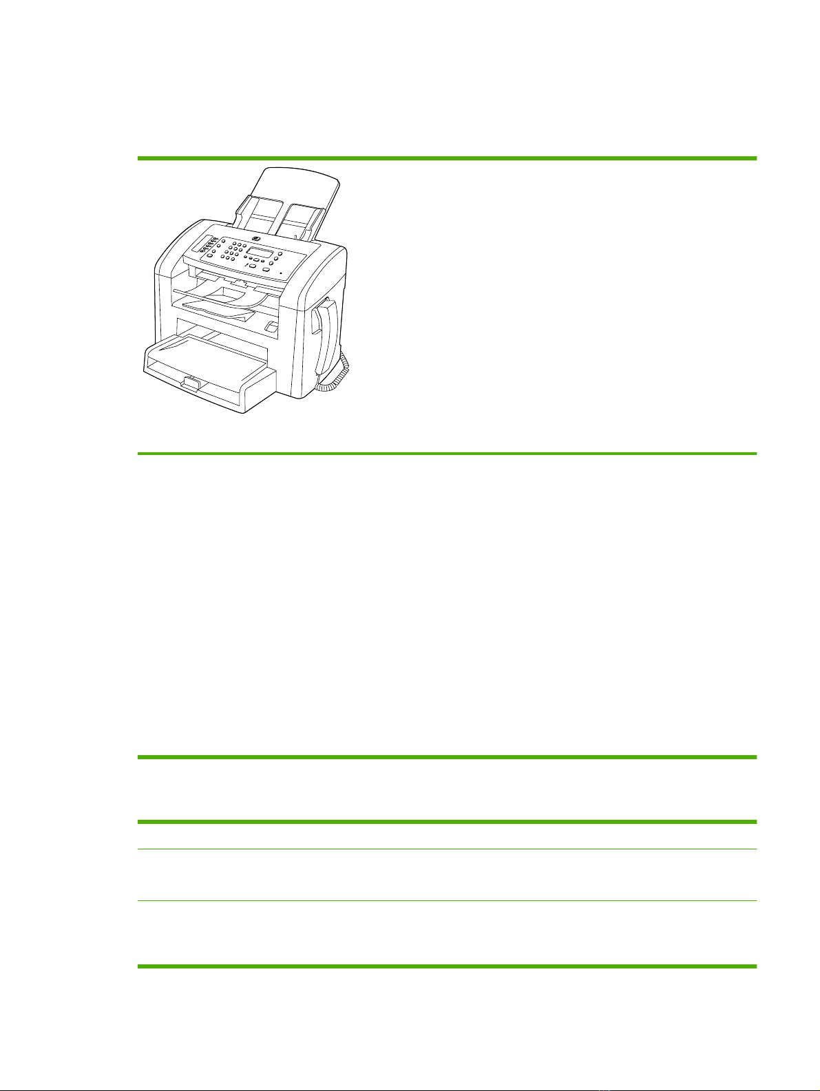
HP LaserJet M1319 MFP Series
Service Manual
Page 2

HP LaserJet M1319 MFP Series
Service Manual
Page 3

Copyright information
© 2008 Copyright Hewlett-Packard
Development Company, L.P.
Reproduction, adaptation, or translation
without prior written permission is prohibited,
except as allowed under the copyright laws.
The information contained herein is subject
to change without notice.
The only warranties for HP products and
services are set forth in the express warranty
statements accompanying such products
and services. Nothing herein should be
construed as constituting an additional
warranty. HP shall not be liable for technical
or editorial errors or omissions contained
herein.
Part number CB536-90938
Edition 1, 4/2008
Safety information
WARNING!
Potential Shock Hazard
Always follow basic safety precautions when
using the product to reduce risk of injury from
fire or electric shock.
Read and understand all instructions in the
user guide.
Observe all warnings and instructions
marked on the product.
Use only a grounded electrical outlet when
connecting the product to a power source. If
you do not know whether the outlet is
grounded, check with a qualified electrician.
Do not touch the contacts on the end of any
of the sockets on the product. Replace
damaged cords immediately.
Unplug the product from wall outlets before
cleaning.
Do not install or use the product near water
or when you are wet.
Trademark credits
Microsoft
®
and Windows® are U.S.
registered trademarks of Microsoft
Corporation.
Windows Vista
®
is either a registered
trademark or trademark of Microsoft
Corporation in the United States and/or other
countries.
®
Intel
Core™ is a trademark of Intel
Corporation in the U.S. and other countries.
Install the product securely on a stable
surface.
Install the product in a protected location
where no one can step on or trip over the
power cord and where the power cord will not
be damaged.
If the product does not operate normally, see
the online user guide.
Refer all servicing questions to qualified
personnel.
Information regarding FCC Class B, Parts 15
and 68 requirements can be found in the user
guide.
Page 4

Table of contents
1 Product information
Quick access to product information .................................................................................................... 2
Product configuration ........................................................................................................................... 3
Configuration table ............................................................................................................... 3
Features table ...................................................................................................................... 3
Product walkaround .............................................................................................................................. 5
Front view ............................................................................................................................ 5
Back view ............................................................................................................................. 6
Interface ports ...................................................................................................................... 6
Location of serial number and model number ..................................................................... 7
Supported operating systems ............................................................................................................... 8
Software included with the product ...................................................................................... 8
Easy installation for Windows ............................................................................. 8
Advanced installation .......................................................................................... 8
Macintosh software ............................................................................................. 9
Supported printer drivers ..................................................................................................... 9
Connectivity .......................................................................................................................................... 9
Connect the product directly to a computer with USB ......................................................... 9
2 Control panel
Control panel walkaround ................................................................................................................... 12
Control-panel menus .......................................................................................................................... 13
Use the control-panel menus ............................................................................................. 13
Control-panel main menus ................................................................................................. 13
3 Paper and print media
Supported paper and print media sizes .............................................................................................. 22
Load paper and print media ............................................................................................................... 23
Priority input tray ................................................................................................................ 23
Tray 1 ................................................................................................................................. 24
Configure trays ................................................................................................................................... 24
4 Manage and maintain
Information pages ............................................................................................................................... 26
ENWW iii
Page 5

Use the HP Toolbox software ............................................................................................................. 27
View HP Toolbox ............................................................................................................... 27
Status ................................................................................................................................. 27
Fax ..................................................................................................................................... 28
Fax tasks ........................................................................................................... 28
Fax phone book ................................................................................................ 28
Fax send log ...................................................................................................... 30
Fax receive log .................................................................................................. 30
Other Links ........................................................................................................................ 30
Manage supplies ................................................................................................................................ 31
Check and order supplies .................................................................................................. 31
Check supplies status by using the control panel ............................................. 31
Store supplies ................................................................................................... 32
HP policy on non-HP supplies ........................................................................... 32
HP fraud hotline ................................................................................................ 32
Recycle supplies ............................................................................................... 32
Replace supplies ............................................................................................................... 33
Print cartridge .................................................................................................... 33
Clean the product .............................................................................................................. 35
Clean the paper path ......................................................................................... 35
Clean the glass and white platen ...................................................................... 35
Clean the exterior .............................................................................................. 36
Firmware updates .............................................................................................................. 36
5 Operational theory
Basic operation ................................................................................................................................... 38
Formatter system ............................................................................................................................... 41
Product base functions ....................................................................................................................... 43
Sequence of operation ...................................................................................................... 39
Sequence of operation, scanner ....................................................................... 39
Sequence of operation, product base ............................................................... 40
Central processing unit ..................................................................................................... 41
Fax card ............................................................................................................................. 41
Standard startup process ................................................................................................... 42
Product startup messages ............................................................................... 42
RAM ................................................................................................................................... 42
USB interface ..................................................................................................................... 42
Control panel ..................................................................................................................... 42
Engine control system (engine control unit and power-supply assembly) ......................... 44
Print-engine control system ............................................................................... 44
Product base laser/scanner .............................................................................. 45
Power system on the power-supply assembly .................................................. 46
AC power distribution ....................................................................... 46
iv ENWW
Page 6

DC power distribution ....................................................................... 46
Overcurrent/overvoltage ................................................................... 46
High-voltage power distribution ........................................................ 47
Image-formation system .................................................................................................... 48
The seven image-formation processes ............................................................ 48
Print cartridge .................................................................................................................... 49
Product base paper-feed system ....................................................................................... 49
Jam detection in the product ............................................................................................. 51
Conditions of jam detection ............................................................................... 51
HP LaserJet M1319f components ...................................................................................................... 52
Basic operation .................................................................................................................. 52
ADF pickup-and-feed system ............................................................................ 54
Optical scanning system ................................................................................... 56
Fax functions and operation .............................................................................................................. 58
Computer and network security features ........................................................................... 58
PSTN operation ................................................................................................................. 58
Receive faxes when you hear fax tones ............................................................................ 59
Distinctive ring function ...................................................................................................... 59
Fax by using Voice over IP services .................................................................................. 59
The fax subsystem ............................................................................................................. 60
Fax card in the fax subsystem ........................................................................................... 60
Safety isolation .................................................................................................. 60
Safety-protection circuitry .................................................................................. 60
Data path ........................................................................................................... 61
Hook state ......................................................................................................... 61
Downstream device detection ........................................................................... 61
Hook switch control ........................................................................................... 62
Ring detect ........................................................................................................ 62
Line current control ........................................................................................... 62
Billing- (metering-) tone filters ........................................................................... 62
Fax page storage in flash memory .................................................................................... 62
Stored fax pages ............................................................................................... 62
Advantages of flash memory storage ............................................................... 63
6 Removal and replacement
Removal and replacement strategy ................................................................................................... 66
Warnings, cautions, notes, and tips ................................................................................... 66
Electrostatic discharge ....................................................................................................... 66
Required tools ................................................................................................................... 67
Types of screws ................................................................................................................. 67
Service approach ............................................................................................................................... 68
Before performing service .................................................................................................. 68
After performing service ..................................................................................................... 69
ENWW v
Page 7

Post-service tests .............................................................................................................. 69
Test 1 (print-quality test) ................................................................................... 69
Test 2 (copy-quality test) ................................................................................... 69
Test 3 (fax-quality test) ...................................................................................... 70
Parts removal order ........................................................................................................... 71
Scanner assemblies ........................................................................................................................... 73
Link assemblies and scanner support-frame spring .......................................................... 73
Scanner side covers .......................................................................................................... 76
Separation-pad set ............................................................................................................ 78
Top cover, control panel .................................................................................................... 79
Control-panel assembly ..................................................................................................... 81
Media lever and media-lever torsion spring ....................................................................... 82
Separation-pad assembly .................................................................................................. 83
Scanner assembly ............................................................................................................. 85
Scanner assembly top cover ............................................................................................. 93
Top-cover assembly .......................................................................................................... 96
Pickup roller ....................................................................................................................... 97
White platen ....................................................................................................................... 98
Product base ...................................................................................................................................... 99
Handset ............................................................................................................................. 99
Separation pad ................................................................................................................ 100
Print cartridge .................................................................................................................. 101
Pickup roller ..................................................................................................................... 102
Installing the scanner cushions ........................................................................................ 105
Media input tray ............................................................................................................... 106
Transfer roller .................................................................................................................. 108
Side covers ...................................................................................................................... 110
Print-cartridge door .......................................................................................................... 112
Rear cover and fuser cover ............................................................................................. 113
Front cover ....................................................................................................................... 115
Speaker assembly ........................................................................................................... 118
Power supply ................................................................................................................... 119
Formatter and fax card .................................................................................................... 122
Scanner support-frame .................................................................................................... 124
Engine controller unit (ECU) ............................................................................................ 127
Laser/scanner assembly .................................................................................................. 131
Main motor ....................................................................................................................... 132
Fuser ................................................................................................................................ 134
Paper-pickup assembly ................................................................................................... 136
7 Solve problems
Problem-solving checklist ................................................................................................................. 138
Menu map ........................................................................................................................................ 140
vi ENWW
Page 8

Print a menu map ............................................................................................................ 140
Tools for troubleshooting .................................................................................................................. 141
Component tests .............................................................................................................. 141
Drum rotation test ............................................................................................ 141
Half self-test functional check ......................................................................... 142
Perform a half self-test check .......................................................................... 142
Perform other checks ...................................................................................... 142
Heating element check .................................................................................... 143
High-voltage contacts check ........................................................................... 143
Check the print-cartridge contacts ................................................ 143
Check the high-voltage connector assembly ................................. 143
Problem-solving diagrams ................................................................................................................ 144
Repetitive image defects ................................................................................................. 144
Component locations ....................................................................................................... 145
Timing diagram, product base ........................................................................................ 148
Main wiring ...................................................................................................................... 148
Formatter PCA and fax card connectors ......................................................................... 151
Control-panel messages .................................................................................................................. 154
Solve control-panel display problems .............................................................................. 154
Alert and warning messages .......................................................................................... 154
Alert and warning message tables .................................................................. 154
Critical error messages .................................................................................................... 156
Critical error message-tables .......................................................................... 156
Solve paper-handling problems ........................................................................................................ 159
Clear jams ........................................................................................................................ 159
Causes of jams ............................................................................................... 159
Where to look for jams .................................................................................... 160
Clear jams from the ADF ................................................................................. 160
Clear jams from the input-tray areas ............................................................... 161
Clear jams from the output bin ........................................................................ 163
Clear jams from the print-cartridge area ......................................................... 164
Avoid repeated jams ...................................................................................... 165
Media-handling problems ................................................................................................ 165
Print-media guidelines ..................................................................................... 165
Solve print-media problems ............................................................................ 166
Performance problems .................................................................................................... 167
Solve image-quality problems .......................................................................................................... 169
Print-quality problems ...................................................................................................... 169
Improve print quality ........................................................................................ 169
Print-quality settings ....................................................................... 169
Checking the print cartridge ........................................................................... 170
To redistribute the toner in the print cartridge ................................. 170
Identify and correct print defects ..................................................................... 170
Print-quality checklist ...................................................................... 170
ENWW vii
Page 9

General print-quality issues ............................................................ 170
Solve copy problems ........................................................................................................................ 175
Prevent copy problems .................................................................................................... 175
Image problems ............................................................................................................... 175
Media-handling problems ................................................................................................ 176
Performance problems .................................................................................................... 178
Solve scan problems ........................................................................................................................ 179
Solve scanned-image problems ...................................................................................... 179
Scan-quality problems ..................................................................................................... 180
Prevent scan-quality problems ........................................................................ 180
Solve scan-quality problems ........................................................................... 180
Solve control-panel display problems ............................................................................................... 181
Solve connectivity problems ............................................................................................................. 182
Solve direct-connection problems .................................................................................... 182
Solve DSL problems ......................................................................................................................... 183
PBX line problems ........................................................................................................... 183
Solve fax with Voice over IP services problems ............................................................................... 184
Service-mode functions .................................................................................................................... 185
NVRAM initialization ........................................................................................................ 185
Super NVRAM initialization .............................................................................................. 185
Password reset or bypass ............................................................................................... 185
Service menu ................................................................................................................... 186
Secondary service menu ................................................................................................. 187
Solve fax problems ........................................................................................................................... 188
General fax troubleshooting ............................................................................................. 188
Fax error messages ........................................................................................................ 190
Alert and warning message tables .................................................................. 190
Fax memory is retained when there is a loss of power .................................................... 194
Fax logs and reports ........................................................................................................ 194
Print all fax reports .......................................................................................... 194
Print individual fax reports ............................................................................... 194
Set the fax activity log to print automatically ................................................... 195
Set the fax error report .................................................................................... 195
Set the fax confirmation report ........................................................................ 196
Include the first page of each fax on the fax confirmation, fax error, and last
call reports ....................................................................................................... 196
Change error correction and fax speed ........................................................................... 196
Set the fax-error-correction mode ................................................................... 196
Change the fax speed ..................................................................................... 197
Problems sending faxes .................................................................................................. 197
Problems receiving faxes ................................................................................................. 200
Performance problems .................................................................................................... 202
8 Parts
viii ENWW
Page 10

Ordering information ......................................................................................................................... 204
Supplies and hinge tool .................................................................................................................... 204
Cable and interface accessories ...................................................................................................... 204
Whole unit replacement .................................................................................................................... 205
Control-panel overlay ....................................................................................................................... 207
Supplementary documentation and support ..................................................................................... 209
Parts lists and diagrams ................................................................................................................... 211
Screws ............................................................................................................................. 211
Scanner components and handset ................................................................................................... 212
External assemblies ......................................................................................................... 212
ADF components ............................................................................................................. 214
Frame assembly .............................................................................................................. 216
Guide assembly ............................................................................................................... 218
Product base .................................................................................................................................... 220
External assemblies and print cartridge ........................................................................... 220
External covers ................................................................................................................ 222
Formatter and fax card .................................................................................................... 224
Internal components ........................................................................................................ 226
Alphabetical parts list ....................................................................................................................... 232
Numerical parts list ........................................................................................................................... 236
Appendix A Service and support
Hewlett-Packard limited warranty statement .................................................................................... 241
Customer self repair warranty service .............................................................................................. 242
Print cartridge limited warranty statement ........................................................................................ 243
Customer support ............................................................................................................................. 243
Repack the device ............................................................................................................................ 244
Appendix B Specifications
Physical specifications ..................................................................................................................... 246
Electrical specifications .................................................................................................................... 246
Power consumption .......................................................................................................................... 246
Environmental specifications ............................................................................................................ 247
Acoustic emissions ........................................................................................................................... 247
Appendix C Regulatory information
FCC compliance ............................................................................................................................... 250
Telephone Consumer Protection Act (United States) ...................................................................... 251
IC CS-03 requirements ..................................................................................................................... 251
EU statement for telecom operation ................................................................................................. 252
New Zealand telecom statements .................................................................................................... 252
Declaration of conformity .................................................................................................................. 253
Certificate of Volatility ....................................................................................................................... 254
ENWW ix
Page 11

Safety statements ............................................................................................................................. 255
Laser safety ..................................................................................................................... 255
Canadian DOC regulations .............................................................................................. 255
EMI statement (Korea) ..................................................................................................... 255
Laser statement for Finland ............................................................................................. 256
Substances table (China) ................................................................................................ 257
Index ................................................................................................................................................................. 259
x ENWW
Page 12

List of tables
Table 1-1 Product guides ................................................................................................................................... 2
Table 2-1 Fax Job status menu ........................................................................................................................ 13
Table 2-2 Fax functions menu .......................................................................................................................... 13
Table 2-3 Copy setup menu ............................................................................................................................. 14
Table 2-4 Reports menu ................................................................................................................................... 14
Table 2-5 Fax setup menu ............................................................................................................................... 15
Table 2-6 System setup menu ......................................................................................................................... 18
Table 2-7 Service menu .................................................................................................................................. 19
Table 3-1 Supported paper and print media sizes ........................................................................................... 22
Table 3-2 Supported envelopes and postcards ............................................................................................... 22
Table 5-1 Basic sequence of operation, scanner ............................................................................................. 39
Table 5-2 Basic sequence of operation, product base ..................................................................................... 40
Table 5-3 Product startup messages ............................................................................................................... 42
Table 5-4 DC power distribution ....................................................................................................................... 46
Table 7-1 Repetitive image defects ................................................................................................................ 144
Table 7-2 Formatter connections ................................................................................................................... 152
Table 7-3 Fax card connections ..................................................................................................................... 153
Table 7-4 General fax troubleshooting ........................................................................................................... 189
Table 7-5 Alert and warning messages ......................................................................................................... 190
Table 8-1 Whole unit replacement, product bundle CB536A ......................................................................... 205
Table 8-2 Control-panel overlay ..................................................................................................................... 207
Table 8-3 Service and training support .......................................................................................................... 209
Table 8-4 User guides .................................................................................................................................... 209
Table 8-5 Getting started guide ...................................................................................................................... 210
Table 8-6 Technical support Web sites .......................................................................................................... 210
Table 8-7 Common fasteners ........................................................................................................................ 211
Table 8-8 External assemblies ....................................................................................................................... 213
Table 8-9 ADF components ........................................................................................................................... 215
Table 8-10 Frame assembly ........................................................................................................................... 217
Table 8-11 Guide assembly ........................................................................................................................... 219
Table 8-12 External assemblies and print cartridge ....................................................................................... 221
Table 8-13 External covers, printer ................................................................................................................ 223
Table 8-14 Formatter and fax card ................................................................................................................. 225
Table 8-15 Internal components (1 of 3) ........................................................................................................ 227
ENWW xi
Page 13

Table 8-16 Internal components (2 of 3) ........................................................................................................ 229
Table 8-17 Internal components (3 of 3) ........................................................................................................ 231
Table 8-18 Alphabetical parts list ................................................................................................................... 232
Table 8-19 Numerical parts list ....................................................................................................................... 236
Table B-1 Physical specifications ................................................................................................................... 246
Table B-2 Electrical specifications .................................................................................................................. 246
Table B-3 Power consumption (average, in watts) ....................................................................................... 246
Table B-4 Environmental specifications ........................................................................................................ 247
Table B-5 Acoustic emissions ....................................................................................................................... 247
xii ENWW
Page 14

List of figures
Figure 5-1 Product configuration block diagram .............................................................................................. 38
Figure 5-2 Functional block diagram (product base) ........................................................................................ 43
Figure 5-3 Laser/scanner operation ................................................................................................................. 45
Figure 5-4 High-voltage power supply circuit ................................................................................................... 47
Figure 5-5 Image-formation block diagram ...................................................................................................... 48
Figure 5-6 Product base paper path ................................................................................................................ 50
Figure 5-7 Basic operation block diagram ........................................................................................................ 52
Figure 5-8 Optical and feed systems ................................................................................................................ 53
Figure 5-9 Feed control (1 of 2) ........................................................................................................................ 54
Figure 5-10 Feed control (2 of 2) ...................................................................................................................... 55
Figure 5-11 Optical system (1 of 2) .................................................................................................................. 56
Figure 5-12 Optical system (2 of 2) .................................................................................................................. 57
Figure 6-1 Phillips and pozidrive screwdriver comparison ............................................................................... 67
Figure 6-2 Parts-removal tree, scanner assembly ........................................................................................... 71
Figure 6-3 Parts-removal tree, product base .................................................................................................... 72
Figure 6-4 Removing the link assemblies and scanner support-frame spring (1 of 4) ..................................... 73
Figure 6-5 Removing the link assemblies and scanner support-frame spring (2 of 4) ..................................... 74
Figure 6-6 Removing the link assemblies and scanner support-frame spring (3 of 4) ..................................... 74
Figure 6-7 Removing the link assemblies and scanner support-frame spring (4 of 4) ..................................... 75
Figure 6-8 Removing the scanner side covers (1 of 2) .................................................................................... 76
Figure 6-9 Removing the scanner side covers (2 of 2) .................................................................................... 77
Figure 6-10 Removing the separation pad ....................................................................................................... 78
Figure 6-11 Removing the top cover, control panel (1 of 3) ............................................................................. 79
Figure 6-12 Removing the top cover, control panel (2 of 3) ............................................................................. 79
Figure 6-13 Removing the top cover, control panel (3 of 3) ............................................................................. 80
Figure 6-14 Removing the control-panel assembly (1 of 2) ............................................................................. 81
Figure 6-15 Removing the control-panel assembly (2 of 2) ............................................................................. 81
Figure 6-16 Removing the media lever and media-lever torsion spring ........................................................... 82
Figure 6-17 Removing the separation-pad assembly (1 of 3) .......................................................................... 83
Figure 6-18 Removing the separation-pad assembly (2 of 3) .......................................................................... 84
Figure 6-19 Removing the separation-pad assembly (3 of 3) .......................................................................... 84
Figure 6-20 Removing the scanner assembly (1 of 14) ................................................................................... 85
Figure 6-21 Removing the scanner assembly (2 of 14) ................................................................................... 85
Figure 6-22 Removing the scanner assembly (3 of 14) ................................................................................... 86
ENWW xiii
Page 15

Figure 6-23 Removing the scanner assembly (4 of 14) ................................................................................... 86
Figure 6-24 Removing the scanner assembly (5 of 14) ................................................................................... 87
Figure 6-25 Removing the scanner assembly (6 of 14) ................................................................................... 87
Figure 6-26 Removing the scanner assembly (7 of 14) ................................................................................... 88
Figure 6-27 Removing the scanner assembly (8 of 14) ................................................................................... 88
Figure 6-28 Removing the scanner assembly (9 of 14) ................................................................................... 89
Figure 6-29 Removing the scanner assembly (10 of 14) ................................................................................. 89
Figure 6-30 Removing the scanner assembly (11 of 14) ................................................................................. 90
Figure 6-31 Removing the scanner assembly (12 of 14) ................................................................................. 91
Figure 6-32 Removing the scanner assembly (13 of 14) ................................................................................. 92
Figure 6-33 Removing the scanner assembly (14 of 14) ................................................................................. 92
Figure 6-34 Removing the scanner assembly top cover (1 of 4) ..................................................................... 93
Figure 6-35 Removing the scanner assembly top cover (2 of 4) ..................................................................... 94
Figure 6-36 Removing the scanner assembly top cover (3 of 4) ..................................................................... 94
Figure 6-37 Removing the scanner assembly top cover (4 of 4) ..................................................................... 95
Figure 6-38 Removing the top-cover assembly (1 of 2) ................................................................................... 96
Figure 6-39 Removing the top-cover assembly (2 of 2) ................................................................................... 96
Figure 6-40 Removing the pickup roller (1 of 2) ............................................................................................... 97
Figure 6-41 Removing the pickup roller (2 of 2) ............................................................................................... 97
Figure 6-42 Removing the white platen (1 of 2) ............................................................................................... 98
Figure 6-43 Removing the white platen (2 of 2) ............................................................................................... 98
Figure 6-44 Remove the handset ..................................................................................................................... 99
Figure 6-45 Removing the separation pad (1 of 2) ........................................................................................ 100
Figure 6-46 Removing the separation pad (2 of 2) ........................................................................................ 100
Figure 6-47 Removing the print cartridge (1 of 2) .......................................................................................... 101
Figure 6-48 Removing the print cartridge (2 of 2) .......................................................................................... 101
Figure 6-49 Removing the pickup roller (1 of 5) ............................................................................................. 102
Figure 6-50 Removing the pickup roller (2 of 5) ............................................................................................. 102
Figure 6-51 Removing the pickup roller (3 of 5) ............................................................................................. 103
Figure 6-52 Removing the pickup roller (4 of 5) ............................................................................................. 103
Figure 6-53 Removing the pickup roller (5 of 5) ............................................................................................. 104
Figure 6-54 Installing the scanner cushions ................................................................................................... 105
Figure 6-55 Removing the media input tray (1 of 3) ....................................................................................... 106
Figure 6-56 Removing the media input tray (2 of 3) ....................................................................................... 106
Figure 6-57 Removing the media input tray (3 of 3) ....................................................................................... 107
Figure 6-58 Removing the transfer roller (1 of 3) ........................................................................................... 108
Figure 6-59 Removing the transfer roller (2 of 3) ........................................................................................... 109
Figure 6-60 Removing the transfer roller (3 of 3) ........................................................................................... 109
Figure 6-61 Removing the side covers (1 of 4) .............................................................................................. 110
Figure 6-62 Removing the side covers (2 of 4) .............................................................................................. 110
Figure 6-63 Removing the side covers (3 of 4) .............................................................................................. 111
Figure 6-64 Removing the side covers (4 of 4) .............................................................................................. 111
Figure 6-65 Removing the print-cartridge door (1 of 2) .................................................................................. 112
Figure 6-66 Removing the print-cartridge door (2 of 2) .................................................................................. 112
xiv ENWW
Page 16

Figure 6-67 Removing the rear cover and fuser cover (1 of 3) ...................................................................... 113
Figure 6-68 Removing the rear cover and fuser cover (2 of 3) ...................................................................... 113
Figure 6-69 Removing the rear cover and fuser cover (3 of 3) ...................................................................... 114
Figure 6-70 Removing the front cover (1 of 5) ............................................................................................... 115
Figure 6-71 Removing the front cover (2 of 5) ............................................................................................... 115
Figure 6-72 Removing the front cover (3 of 5) ............................................................................................... 116
Figure 6-73 Removing the front cover (4 of 5) ............................................................................................... 116
Figure 6-74 Removing the front cover (5 of 5) ............................................................................................... 117
Figure 6-75 Removing the speaker assembly (1 of 2) ................................................................................... 118
Figure 6-76 Removing the speaker assembly (2 of 2) ................................................................................... 118
Figure 6-77 Removing the power supply (1 of 5) ........................................................................................... 119
Figure 6-78 Removing the power supply (2 of 5) ........................................................................................... 119
Figure 6-79 Removing the power supply (3 of 5) ........................................................................................... 120
Figure 6-80 Removing the power supply (4 of 5) ........................................................................................... 120
Figure 6-81 Removing the power supply (5 of 5) ........................................................................................... 121
Figure 6-82 Removing the formatter (1 of 4) .................................................................................................. 122
Figure 6-83 Removing the formatter (2 of 4) .................................................................................................. 122
Figure 6-84 Removing the formatter (3 of 4) .................................................................................................. 123
Figure 6-85 Removing the formatter (4 of 4) .................................................................................................. 123
Figure 6-86 Removing the scanner support-frame (1 of 4) ............................................................................ 124
Figure 6-87 Removing the scanner support-frame (2 of 4) ............................................................................ 125
Figure 6-88 Removing the scanner support-frame (3 of 4) ............................................................................ 125
Figure 6-89 Removing the scanner support-frame (4 of 4) ............................................................................ 126
Figure 6-90 Removing the ECU (1 of 6) ......................................................................................................... 127
Figure 6-91 Removing the ECU (2 of 6) ......................................................................................................... 128
Figure 6-92 Removing the ECU (3 of 6) ......................................................................................................... 128
Figure 6-93 Removing the ECU (4 of 6) ......................................................................................................... 129
Figure 6-94 Removing the ECU (5 of 6) ......................................................................................................... 129
Figure 6-95 Removing the ECU (6 of 6) ......................................................................................................... 130
Figure 6-96 Removing the laser/scanner assembly ....................................................................................... 131
Figure 6-97 Removing the main motor (1 of 2) .............................................................................................. 132
Figure 6-98 Removing the main motor (2 of 2) .............................................................................................. 133
Figure 6-99 Removing the fuser assembly (1 of 2) ........................................................................................ 134
Figure 6-100 Removing the fuser assembly (2 of 2) ...................................................................................... 135
Figure 6-101 Removing the paper-pickup assembly ...................................................................................... 136
Figure 7-1 Major components ........................................................................................................................ 145
Figure 7-2 Solenoid, sensors, switches, and motor ....................................................................................... 146
Figure 7-3 PCAs ............................................................................................................................................. 147
Figure 7-4 Timing diagram, product base ...................................................................................................... 148
Figure 7-5 Main wiring, scanner assembly ..................................................................................................... 149
Figure 7-6 Main wiring, product base (110 V) ................................................................................................ 150
Figure 7-7 Main wiring, product base (220 V) ................................................................................................ 151
Figure 7-8 Formatter connections .................................................................................................................. 152
Figure 7-9 Fax card connections .................................................................................................................... 153
ENWW xv
Page 17

Figure 8-1 External assemblies ...................................................................................................................... 212
Figure 8-2 ADF components .......................................................................................................................... 214
Figure 8-3 Frame assembly ........................................................................................................................... 216
Figure 8-4 Guide assembly ............................................................................................................................ 218
Figure 8-5 External assemblies and print cartridge ........................................................................................ 220
Figure 8-6 External covers ............................................................................................................................. 222
Figure 8-7 Formatter and fax card .................................................................................................................. 224
Figure 8-8 Internal components (1 of 3) ......................................................................................................... 226
Figure 8-9 Internal components (2 of 3) ......................................................................................................... 228
Figure 8-10 Internal components (3 of 3) ....................................................................................................... 230
xvi ENWW
Page 18

1 Product information
Quick access to product information
●
Product configuration
●
Product walkaround
●
Supported operating systems
●
Connectivity
●
ENWW 1
Page 19

Quick access to product information
Use the following Web site to find information about the product.
www.hp.com/support/ljm1319
●
Table 1-1 Product guides
Guide Description
HP LaserJet M1319 MFP Getting
Started Guide
HP LaserJet M1319 MFP Series
User Guide
HP ToolboxFX To check the product status and settings, and to view problem-solving information and online
Online Help Provides information about options that are available in the printer drivers. To view a Help
Provides step-by-step instructions for installing and setting up the product.
Provides detailed information for using the product and problem-solving. Available on the
product CD or in the Windows Program Group if the software is installed on a computer.
documentation, use the HP ToolboxFX. You must have performed a complete software
installation in order to use the HP ToolboxFX. See the user guide for more information about
software installation.
file, open the online Help through the printer driver.
2 Chapter 1 Product information ENWW
Page 20
Product configuration
Configuration table
HP LaserJet M1319f MFP
Prints letter-size pages at speeds up to 19 pages per minute (ppm) and A4-size pages at speeds up to 18 ppm.
●
Tray 1 holds up to 250 sheets of print media or up to 10 envelopes.
●
The priority input tray holds up to 10 sheets of print media.
●
Manual two-sided (duplex) printing, fax receiving, and copying.
●
Average yield for the standard black print cartridge is 2,000 pages, in accordance with ISO/IEC 19752. Actual yield depends
●
on specific use.
Hi-Speed USB 2.0 port and one telephone handset port.
●
V.34 fax modem and 4-megabyte (MB) flash fax-storage memory.
●
Two RJ-11 fax phone cable ports.
●
32-MB random-access memory (RAM).
●
30-page automatic document feeder (ADF).
●
Integrated telephone handset.
●
Features table
Performance
Print quality
Fax
Prints letter-size pages at speeds up to 19 ppm and A4-size pages at speeds up to 18 ppm.
●
Prints at 600 dots per inch (dpi) and FastRes 1200 dpi.
●
Includes adjustable settings to optimize print quality.
●
Full-functionality fax capabilities with a V.34 fax; includes a phone book, fax/tel, and
●
delayed-fax features.
4 MB flash fax-storage memory.
●
ENWW Product configuration 3
Page 21

Copy
Copies at 300 dots per inch (dpi).
●
Scan
Memory
Paper handling
Printer driver features
Interface connections
Economical printing
Supplies
Telephone handset A integrated telephone handset for making and receiving voice calls at the product.
Accessibility
Provides 600 pixels per inch (ppi) full-color scanning.
●
Includes 32-megabyte (MB) random-access memory (RAM).
●
30–page ADF.
●
Priority input tray holds up to 10 pages.
●
Tray 1 holds up to 250 sheets of print media or 10 envelopes.
●
Output bin holds up to 100 sheets of print media.
●
FastRes 1200 produces 1200-dots-per-inch (dpi) print quality for fast, high-quality printing
●
of business text and graphics.
Hi-Speed USB 2.0 port.
●
Two RJ-11 fax/phone cable ports.
●
N-up printing (printing more than one page on a sheet).
●
Manual two-sided printing, faxing, and copying.
●
EconoMode setting (uses less toner).
●
The product ships with a 1,000-page (average yield) starter cartridge. The average yield
●
for replacement cartridges is 2,000 pages, in accordance with ISO/IEC 19752.
Online user guide that is compatible with text screen-readers.
●
Print cartridges can be installed and removed using one hand.
●
All doors and covers can be opened using one hand.
●
4 Chapter 1 Product information ENWW
Page 22
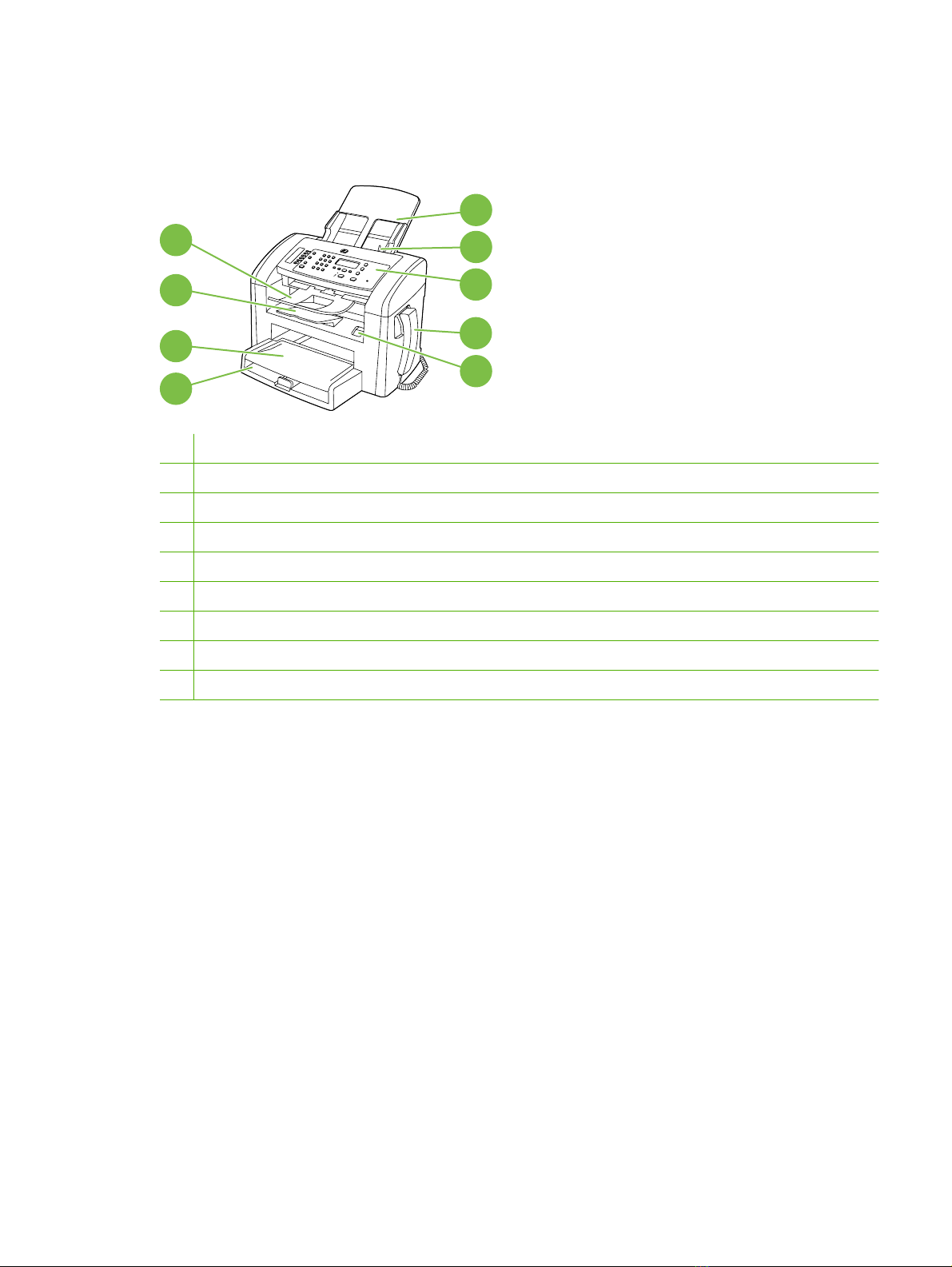
Product walkaround
Front view
5
4
3
2
1
1 Tray 1
2 Priority input tray
3 Output bin
4 Automatic document feeder (ADF) output bin
5 Automatic document feeder (ADF) input tray
6 ADF media lever
7 Control panel
8 Telephone handset
9 Print-cartridge door latch
6
7
8
9
ENWW Product walkaround 5
Page 23
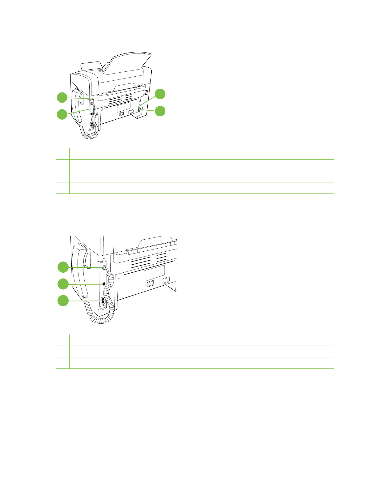
Back view
11
10
10 Interface ports
11 Kensington lock
12 Power switch
13 Power connector
Interface ports
The product has a Hi-Speed USB 2.0 port, fax and phone ports, and a handset port.
1
12
13
2
3
1 Handset port
2 Hi-Speed USB 2.0 port
3 Fax ports
6 Chapter 1 Product information ENWW
Page 24

Location of serial number and model number
ENWW Product walkaround 7
Page 25

Supported operating systems
The product supports the following operating systems:
Full software installation
®
Windows
●
Windows Vista
●
Mac OS X v10.3, v10.4, and later
●
XP (32-bit and 64-bit)
®
(32-bit)
NOTE: For Mac OS X v10.4 and later, PPC and Intel® Core™ Processor Macs are supported.
Software included with the product
There are several options for completing a recommended installation. Easy Install will complete the
installation with default settings. Advanced Install allows you to select custom settings and choose the
components that are installed.
Easy installation for Windows
HP drivers
●
Printer driver
◦
Scan driver
◦
Print and scan drivers only
Windows XP (64-bit)
●
Windows Vista (64-bit)
●
Windows 2000
●
Windows 2003 Server (32-bit and 64-bit)
●
Fax driver
◦
HP MFP software
●
HP LaserJet Scan program
◦
HP Fax Send Fax program
◦
HP Toolbox program
◦
HP Toolbox provides links to product status information and Help information, such as the
user guide, and tools for product problem-solving.
Uninstall program
◦
Other programs
●
Readiris OCR (not installed with other software; separate installation is required)
◦
Advanced installation
Advanced installation includes all of the features that are available with the easy installation. The
HP Customer Participation program is optional.
8 Chapter 1 Product information ENWW
Page 26

Macintosh software
HP Product Setup Assistant
●
HP Uninstaller
●
HP LaserJet software
●
HP Scan
◦
HP Director
◦
HP Director is a software program for working with documents. When the document is loaded
into the ADF and the computer is connected directly to the product, HP Director appears on
the computer screen to initiate faxing, scanning, or changing settings on the product through
Macintosh Configure Device.
HP Director also includes the HP product Setup Assistant for setting up fax and print queues.
Scan to e-mail program
◦
Supported printer drivers
The most recent drivers are available at www.hp.com/support/ljm1319. Depending on the configuration
of Windows-based computers, the installation program for the product software automatically checks
the computer for Internet access to obtain the latest drivers.
Connectivity
Connect the product directly to a computer with USB
NOTE: Do not connect the USB cable from the product to the computer until the installer prompts you
to do so.
1. Insert the product CD into your computer. If the software installer does not start, navigate to the
setup.exe file on the CD and double-click the file.
2. Follow the installer instructions.
3. Allow the installation process to complete, and then restart the computer.
ENWW Connectivity 9
Page 27

2 Control panel
Control panel walkaround
●
Control-panel menus
●
ENWW 11
Page 28

Control panel walkaround
1
1 Fax controls. Use to change commonly used fax settings.
2 Alphanumeric buttons. Use to type data into the product control-panel display and to dial telephone numbers for faxing.
3 Setup and cancel controls. Use to select menu options, determine the product status, and cancel the current job.
4 Copy controls. Use to change commonly used default settings and to start copying.
2 3
4
12 Chapter 2 Control panel ENWW
Page 29

Control-panel menus
Use the control-panel menus
To gain access to the control-panel menus, use the following steps.
1. Press Setup.
2. Use the arrow buttons to navigate the listings.
Press OK to select the appropriate option.
●
Press Cancel to cancel an action or return to the Ready state.
●
Control-panel main menus
Use the Fax Job status menu to display a list of all faxes that are waiting to be sent, or that have
●
been received but are waiting to be printed, forwarded, or uploaded to the computer.
Use the Fax functions menu to configure fax functions such as scheduling a delayed fax,
●
cancelling the Receive to PC mode, reprinting faxes that were previously printed, or printing faxes
that are stored in memory.
Use the Copy setup menu to configure basic copy default settings such as contrast, collation, or
●
the number of copies printed.
Use the Reports menu to print reports that provide information about the product.
●
Use the Fax setup menu to configure the fax phone book, the outgoing and incoming fax options,
●
and the basic settings for all faxes.
Use the System setup menu to establish basic product settings such as language, print quality,
●
or volume levels.
Use the Service menu to restore default settings, clean the product, and activate special modes
●
that affect print output.
NOTE: To print a detailed list of the entire control-panel menu and its structure, print a menu structure
report. See
Table 2-1 Fax Job status menu
Menu item Description
Fax Job status Displays pending fax jobs, and allows you to cancel pending fax jobs.
Table 2-2 Fax functions menu
Menu item Description
Send fax later Allows a fax to be sent at a later time and date.
Stop Recv to PC Disables the Receive to PC setting that allows a computer to upload all current faxes that have
Information pages on page 26.
not been printed and all future faxes received by the product.
Reprint last Reprints the faxes that are stored in the product memory.
ENWW Control-panel menus 13
Page 30

Table 2-2 Fax functions menu (continued)
Menu item Description
Polling receive Allows the product to call another fax machine that has polling send enabled.
Clear saved faxs Clears all faxes in the product memory.
Table 2-3 Copy setup menu
Menu item Sub-menu item Description
Default Quality Text
Draft
Mixed
Film photo
Picture
Def. Light/dark Sets the default contrast option.
Def. # of copies (Range: 1-99) Sets the default number of copies.
Def. Reduce/Enlrg Original=100%
A4->Ltr=94%
Ltr->A4=97%
Full Page=91%
2 pages/sheet
4 pages/sheet
Custom:25-400%
Restore defaults Sets all customized copy settings to the factory default
Sets the default copy quality.
Sets the default percentage to reduce or enlarge a copied
document.
values.
Table 2-4 Reports menu
Menu Item Sub-menu item Sub-menu item Description
Demo page Prints a page that demonstrates print quality.
14 Chapter 2 Control panel ENWW
Page 31

Table 2-4 Reports menu (continued)
Menu Item Sub-menu item Sub-menu item Description
Fax Reports Fax Confirmation Never
Send fax only
Receive fax
Every fax
Fax Error report Every error
Send Error
Receive Error
Never
Last Call report Prints a detailed report of the last fax operation, either
Include 1st page On
Off
Fax Activity log Print log now
Auto Log Print
PhoneBook report Prints a list of the speed dials that have been set up for
Sets whether or not the product prints a confirmation
report after successfully sending or receiving a job.
Sets whether or not the product prints a report after
failing to send or receive a job.
sent or received.
Sets whether or not the product includes a thumbnail
image of the first page of the fax on the report.
Print log now: Prints a list of the last 50 faxes that have
been sent from or received by this product.
Auto Log Print: Select On to automatically print a report
after every fax job. Select Off to turn off the automatic
print feature.
this product.
Block Fax list Prints a list of phone numbers that are blocked from
sending faxes to this product.
All fax reports Prints all fax-related reports.
Menu structure Prints a control-panel menu layout map and lists the
Config report Prints a list of all the product settings.
active settings for each menu.
Table 2-5 Fax setup menu
Menu Item Sub-menu item Sub-menu item Description
Fax header Your fax number
Company name
Phone Book Individual setup Add/Edit
Group setup
Delete all
Sets the identifying information that is sent to the receiving
Delete
Add/Edit group
Delete group
Del. # in group
product.
Edits the fax phone book speed-dials and group-dial entries.
The product supports up to 120 phone book entries, which
can be either individual or group entries.
ENWW Control-panel menus 15
Page 32

Table 2-5 Fax setup menu (continued)
Menu Item Sub-menu item Sub-menu item Description
Fax Send setup Def. Resolution Fine
Superfine
Photo
Standard
Def. light/dark Sets the darkness of outgoing faxes.
Dialing Mode Tone
Pulse
Redial if busy On
Off
Redial-no answer On
Off
Redial Comm Err. On
Off
Dial Prefix On
Off
Detect dial tone On
Off
Sets the resolution for sent documents. Higher resolution
images have more dots per inch (dpi), so they show more
detail. Lower resolution images have fewer dots per inch and
show less detail, but the file size is smaller.
Changing the resolution setting might affect the fax speed.
Sets whether the product should use tone or pulse dialing.
Sets whether or not the product should attempt to redial if
the line is busy.
Sets whether the product should attempt to dial if the
recipient fax number does not answer.
Sets whether the product should attempt to redial the
recipient fax number if a communication error occurs.
Specifies a prefix number that must be dialed when sending
faxes from the product.
Sets whether the product should check for a dial tone before
sending a fax.
16 Chapter 2 Control panel ENWW
Page 33

Table 2-5 Fax setup menu (continued)
Menu Item Sub-menu item Sub-menu item Description
Fax Recv. setup Answer mode Automatic
Manual
Rings to answer (Range of 1-9) Sets the number of rings that must occur before the fax
Answer Ring Type All Rings
Single
Double
Triple
Double&Triple
Sets the type of answer mode.
Automatic: The product automatically answers an
●
incoming call on the configured number of rings.
Manual : The user must press the Start Fax button or
●
use an extension phone to make the product answer
the incoming call.
modem answers.
Allows a user to have two or three phone numbers on a
single line, each with a different ring pattern (only on a phone
system with distinctive-ring service).
All Rings: The product answers any calls that come
●
through the telephone line.
Single: The product answers any calls that produce a
●
single-ring pattern.
Double: The product answers any calls that produce a
●
double-ring pattern.
Triple: The product answers any calls that produce a
●
triple-ring pattern.
Double&Triple: The product answers any calls that
●
produce a double-ring or triple-ring pattern.
Extension Phone On
Off
Silence Detect On
Off
Fit to page On
Off
Stamp faxes On
Off
Forward fax On
Off
When this feature is enabled, the user can press the 1-2-3
buttons on the extension phone to cause the product to
answer an incoming fax call.
Sets whether the product can receive faxes from older
model fax machines that do not emit the initial fax tones used
during fax transmission.
Shrinks faxes that are larger than Letter-size or A4-size so
that they can fit onto a Letter-size or A4-size page. If this
feature is set to Off, faxes larger than Letter or A4 will print
on multiple pages.
Sets the product to add the date, time, sender's phone
number, and page number to each page of the faxes that
this product receives.
Sets the product to send all received faxes to another fax
machine.
ENWW Control-panel menus 17
Page 34

Table 2-5 Fax setup menu (continued)
Menu Item Sub-menu item Sub-menu item Description
Block faxes Add entry
Delete entry
Clear all
Reprint faxes On
Off
Private receive On
Off
All faxes Error correction On
Off
Fax Speed Fast(V.34)
Medium(V.17)
Modifies the blocked fax list. The blocked fax list can contain
up to 30 numbers. When the product receives a call from
one of the blocked fax numbers, it deletes the incoming fax.
It also logs the blocked fax and job-accounting information
in the activity log.
Sets whether all received faxes stored in available memory
can be reprinted.
Setting Private receive to On requires the user to have set
a password in product security. After the password is set,
the following options are set:
Private receive is turned on.
●
All old faxes are deleted from memory.
●
Fax forwarding or Receive to PC are set to On and
●
are not allowed to be changed.
All incoming faxes are stored in memory.
●
Sets whether the product sends or receives the error portion
again when a fax transmission error occurs.
Increases or decreases the allowed fax communication
speed.
Slow(V.29)
Table 2-6 System setup menu
Menu Item Sub-menu item Sub-menu item Description
Language (List of available
control-panel
display languages.)
Paper setup Def. paper size Letter
Def. paper type Lists available
Print Density (Range of 1-5) Sets how much toner the product should use to darken lines
Sets the language in which the control panel displays
A4
Legal
media types.
messages and product reports.
Sets the size for printing internal reports or for any print job
that does not specify a size.
Sets the type for printing internal reports or for any print job
that does not specify a type.
and edges.
18 Chapter 2 Control panel ENWW
Page 35

Table 2-6 System setup menu (continued)
Menu Item Sub-menu item Sub-menu item Description
Volume settings Alarm volume Soft
Ring volume
Key-press volume
Phoneline volume
Handset volume
Time/Date (Settings for time
format, current time,
date format, and
current date.)
Medium
Loud
Off
Sets the time and date setting for the product.
Sets the volume levels for the product.
Table 2-7 Service menu
Menu item Sub-menu item Description
Print T.30 trace Never
Now
If error
At end of call
Restore defaults Sets all customized settings to the factory default values.
Prints or schedules a report that is used to troubleshoot fax
transmission issues.
Cleaning Mode Cleans the product when specks or other marks appear on printed
output. The cleaning process removes dust and excess toner from
the paper path.
When selected, the product prompts you to load plain Letter or A4
paper in tray 1. Press OK to begin the cleaning process. Wait until
the process completes. Discard the page that prints.
Less paper curl On
Off
Archive print On
Off
When printed pages are consistently curled, this option sets the
product to a mode that reduces curl.
The default setting is Off.
When printing pages that will be stored for a long time, this option
sets the product to a mode that reduces toner smearing and
dusting.
The default setting is Off.
ENWW Control-panel menus 19
Page 36

3 Paper and print media
Supported paper and print media sizes
●
Load paper and print media
●
Configure trays
●
ENWW 21
Page 37

Supported paper and print media sizes
This product supports a number of paper sizes, and it adapts to various media.
NOTE: To obtain best print results, select the appropriate paper size and type in the print driver before
printing.
Table 3-1 Supported paper and print media sizes
Size Dimensions Priority input tray Tray 1
Letter 216 x 279 mm (8.5 x 11 inches)
Legal 216 x 356 mm (8.5 x 14 inches)
A4 210 x 297 mm (8.27 x 11.69 inches)
Executive 184 x 267 mm (7.24 x 10.51 inches)
A3 297 x 420 mm (11.69 x 16.54 inches)
A5 148 x 210 mm (5.83 x 8.27 inches)
A6 105 x 148 mm (4.13 x 5.83 inches)
B5 (JIS) 182 x 257 mm (7.17 x 10.12 inches)
16k 197 x 273 mm (7.75 x 10.75 inches)
16k 195 x 270 mm (7.7 x 10.6 inches)
16k 184 x 260 mm (7.25 x 10.25 inches)
8.5 x 13 216 x 330 mm (8.5 x 13 inches)
1
4 x 6
1
5 x 8
10 x 15 cm
Custom Priority input tray: Minimum—76 x127 mm (3 x
1
These sizes are supported as custom sizes.
1
107 x 152 mm (4 x 6 inches)
127 x 203 mm (5 x 8 inches)
100 x 150 mm (3.9 x 5.9 inches)
5 inches); Maximum—216 x 356 mm (8.5 x
14 inches)
Table 3-2 Supported envelopes and postcards
Size Dimensions Priority input tray Tray 1
Envelope #10 105 x 241 mm (4.13 x 9.49 inches)
Envelope DL 110 x 220 mm (4.33 x 8.66 inches)
Envelope C5 162 x 229 mm (6.93 x 9.84 inches)
Envelope B5 176 x 250 mm (6.7 x 9.8 inches)
Envelope Monarch 98 x 191 mm (3.9 x 7.5 inches)
Postcard 100 x 148 mm (3.94 x 5.83 inches)
Double postcard 148 x 200 mm (5.83 x 7.87 inches)
22 Chapter 3 Paper and print media ENWW
Page 38

Load paper and print media
Priority input tray
The priority input tray is accessed from the front of the product. The product prints from the priority input
tray before attempting to print from tray 1.
The priority input tray holds up to 10 sheets of 75 g/m2 (20 lb) media or one envelope, one transparency,
or one card. You can use the priority input tray to print the first page on media different from the remainder
of the document.
Media guides ensure that the media is correctly fed into the product and that the print is not skewed
(crooked on the media). When loading media, adjust the media guides to match the width of the media
that you are using.
ENWW Load paper and print media 23
Page 39

Tray 1
Tray 1 holds up to 250 pages of 75 g/m2 (20 lb) paper, or fewer pages of heavier media (25 mm (0.9 in)
or less stack height). Load media with the top forward and the side to be printed on facing down.
Media guides ensure that the media feeds correctly into the product and that the print is not skewed.
Tray 1 has side and rear media guides. When loading media, adjust the media guides to match the
length and width of the media that you are using.
NOTE: When you add new media, make sure that you remove all of the media from the input tray and
straighten the stack of new media. Do not fan the media. This reduces jams by preventing multiple
sheets of media from feeding through the product at one time.
Configure trays
To set the default paper size or type from the control panel, complete the following steps.
Configure trays for copy jobs
1. On the product control panel, press Setup.
2. Use the arrow buttons to select System setup, and then press OK.
3. Use the arrow keys to select Paper setup, and then press OK.
4. Use the arrow keys to select either Def. paper size or Def. paper type, and then press OK.
5. Use the arrow keys to select a default type or size for the tray, and then press OK.
NOTE: To configure the product trays for print jobs, use the printer driver.
24 Chapter 3 Paper and print media ENWW
Page 40

4 Manage and maintain
Information pages
●
Use the HP Toolbox software
●
Manage supplies
●
ENWW 25
Page 41

Information pages
Information pages reside within the product memory. These pages help diagnose and solve problems
with the product.
NOTE: If the product language was not correctly set during installation, you can set the language
manually so the information pages print in one of the supported languages. Change the language by
using the System setup menu on the control panel. See
Page description How to print the page
Control-panel menus on page 13.
Configuration page
Shows the current settings and product properties.
Demo page
Contains examples of text and graphics.
Menu map
Shows the control-panel menus and available settings.
Fax reports For information about fax logs and reports, see Fax logs and
1. On the product control panel, press Setup.
2. Use the arrow buttons to select Reports, and then press
OK.
3. Use the arrow buttons to select Config report, and then
press OK.
A second page also prints. On that page, the Fax Settings
section provides details about the product fax settings.
1. On the product control panel, press Setup.
2. Use the arrow buttons to select Reports, and then press
OK.
3. Use the arrow buttons to select Demo page, and then
press OK.
1. On the product control panel, press Setup.
2. Use the arrow buttons to select Reports, and then press
OK.
3. Use the arrow buttons to select Menu structure, and then
press OK.
reports on page 194.
26 Chapter 4 Manage and maintain ENWW
Page 42

Use the HP Toolbox software
NOTE: You must perform a full software installation to use the HP Toolbox.
HP Toolbox is a software program that you can use for the following tasks:
Check the product status
●
Configure the product settings
●
Configure pop-up-alert messages
●
View troubleshooting information
●
View online documentation
●
View HP Toolbox
Open HP Toolbox in one of these ways:
●
In the Windows system tray, double-click the product icon (
On the Windows Start menu, click Programs (or All Programs in Windows XP), click HP, click
●
HP LaserJet M1319, and then click HP Toolbox.
The HP Toolbox software contains the following sections for each product in the Devices window:
).
Status
Status
●
Fax
●
In addition to these sections, every page contains the following common elements:
Shop for Supplies
●
Other links
●
The Status folder contains a link to the Device Status main page. Use this page to view product status
information. This page indicates product conditions such as a jam or an empty tray. After you correct a
product problem, click Refresh status to update the product status.
ENWW Use the HP Toolbox software 27
Page 43

Fax
Use the HP Toolbox Fax tab to perform fax tasks from your computer. The Fax tab contains links to the
following main pages:
●
●
●
●
●
Fax tasks
The following three options are available when receiving a fax:
●
●
Fax Tasks. Perform such tasks as sending a fax or clearing the fax memory, or set the fax receive
mode.
Fax Phone Book. Add, edit, or delete entries in the product phone book.
Fax Send Log. View all of the recent faxes that have been sent from the product.
Fax Receive Log. View all of the recent faxes that have been received by the product.
Fax Data Properties. Manage the space used to store faxes on a computer. These settings apply
only if you have chosen to send or receive faxes remotely from a computer.
Print the fax. You can have a message appear on your computer to notify you when the fax was
printed.
Receive the fax on your computer. You can have a message appear on your computer to notify
you when the fax arrives. If the fax machine is connected to multiple computers, only one computer
can be designated to receive faxes.
Forward the fax to another fax machine.
●
NOTE: You must click Apply for the changes to take effect.
Fax phone book
Use the HP Toolbox Fax phone book to add and remove individuals or groups on your speed-dial list,
import phone books from a variety of sources, and update and maintain your contact list.
To add an individual contact to your speed-dial list, select the check box next to the speed dial
●
number that you want to specify. Type the contact name in the Contact name window. Type the
fax number in the Fax number window. Click Add/Edit.
To add a group of contacts to your speed-dial list, select the check box next to the speed-dial
●
number that you want to specify. Click New/Edit Group. Double-click a contact name from the list
on the left to move it to the group list on the right, or select a name on the left and then click the
appropriate arrow to move it to the group list on the right. You can also use those two methods to
move names from right to left. When you have created a group, type a name in the Group name
window, and then click OK.
To edit an existing individual speed-dial entry, click anywhere on the row containing the contact
●
name to select it, type changes in the appropriate windows, and then click Add/Edit. You can also
make changes directly in the phone book directory list by clicking the entry and typing your changes.
Be sure that no check marks appear in the Select column.
To edit an existing group-speed-dial entry, click anywhere on the row containing the group name
●
to select it, and then click New/Edit Group. Make any required changes, and then click OK. You
can make changes to the name of the group directly in the phone book directory list by clicking the
entry and typing your changes. Be sure that no check marks appear in the Select column.
28 Chapter 4 Manage and maintain ENWW
Page 44

To delete an entry from the speed-dial list, select the item and then click Delete.
●
To move speed dial entries, select the entry and then click Move, or select Move and then specify
●
the entry in the dialog box. Then either select Next empty row or specify the number of the row
where you want to move the entry.
NOTE: If you specify a row that is occupied, the new entry will overwrite the existing entry.
To import contacts from a phone book that exists in Lotus Notes, Outlook, or Outlook Express, click
●
Import Phone Book. Select the appropriate software program, navigate to the appropriate file,
and then click OK. You can also select individual entries from the phone book instead of importing
the entire phone book.
To select all of the entries in your speed-dial list, click the Select column heading.
●
In addition to numerical digits, the following are valid characters for fax numbers:
(
●
)
●
+
●
-
●
*
●
#
●
R
●
W
●
.
●
,
●
<space>
●
NOTE: You must click Apply for the changes to take effect.
ENWW Use the HP Toolbox software 29
Page 45

Fax send log
The HP Toolbox Fax send log lists all recently sent faxes and information about them, including the date
and time sent, job number, fax number, page count, and the results.
When you send a fax from a computer that is connected to the product, the fax contains a View link.
Clicking this link opens a new page that provides information about the fax.
Click any column heading in the Fax send log to re-sort the information in that column in ascending or
descending order.
The Results column provides the status of the fax. If the fax attempt was unsuccessful, this column
provides a description of why the fax was not sent.
NOTE: You must click Apply for the changes to take effect.
Fax receive log
The HP Toolbox Fax receive log provides a list of all recently received faxes and information about them
including the date and time received, job number, fax number, page count, results, and an abbreviated
fax image.
When you receive a fax on a computer that is connected to the product, the fax contains a View link.
Clicking this link opens a new page that provides information about the fax.
Click on any column heading in the Fax receive log to re-sort the information in that column in ascending
or descending order.
The Results column provides the status of the fax. If the fax attempt was unsuccessful, this column
provides a description of why the fax was not received.
NOTE: You must click Apply for the changes to take effect.
Other Links
This section contains links that connect you to the Internet. You must have Internet access to use any
of these links. If you use a dial-up connection and did not connect when you first opened the HP Toolbox,
you must connect before you can visit these Web sites. Connecting might require that you close the
HP Toolbox and reopen it.
HP Instant Support. Connects to the HP Instant Support Web site.
●
Product Support. Connects to the support site for the product where you can search for help with
●
a specific problem.
Shop for Supplies. Order supplies at the HP Web site.
●
Product Registration. Connects to the HP product registration Web site.
●
30 Chapter 4 Manage and maintain ENWW
Page 46

Manage supplies
Check and order supplies
You can check the supplies status by using the product control panel, printing a supplies status page,
or viewing HP Toolbox. Hewlett-Packard recommends that you place an order for a replacement print
cartridge when Low message for a print cartridge first appears. Use a new, authentic HP print cartridge
to obtain the following types of supplies information:
Amount of cartridge life remaining
●
Estimated number of pages remaining
●
Number of pages printed
●
Other supplies information
●
NOTE: You can set HP Toolbox to notify you when supplies are low.
Check supplies status by using the control panel
Check the product control panel, which indicates when a print cartridge is low or empty.
If the supplies levels are low, you can order supplies through a local HP dealer, by telephone, or online.
Parts on page 203 for part numbers. Go to www.hp.com/go/ljsupplies to order online.
See
ENWW Manage supplies 31
Page 47

Store supplies
Follow these guidelines for storing print cartridges:
Do not remove the print cartridge from its package until you are ready to use it.
●
CAUTION: To prevent damage, do not expose the print cartridge to light for more than a few
minutes.
See
●
●
●
Specifications on page 245 for operating and storage temperature ranges.
Store the supply in a horizontal position.
Store the supply in a dark, dry location away from heat and magnetic sources.
HP policy on non-HP supplies
Hewlett-Packard Company cannot recommend the use of non-HP supplies, either new or
remanufactured. Because they are not HP products, HP cannot influence their design or control their
quality. Service or repairs required as a result of using a non-HP supply will not be covered under the
warranty.
HP fraud hotline
Call the HP fraud hotline if the product or HP Toolbox indicates that the print cartridge is not an HP print
cartridge and you think that it is genuine. HP will help determine if the product is genuine and take steps
to resolve the problem.
The print cartridge might not be a genuine HP one if you notice the following issues:
You are experiencing a large number of problems with the print cartridge.
●
The print cartridge does not look like it usually does (for example, the pull tab or the box is different).
●
In the United States, call toll-free: 1-877-219-3183.
Outside the United States, you can call collect. Dial the operator and ask to place a collect call to this
telephone number: 1-770-263-4745. If you do not speak English, a representative at the HP fraud hotline
who speaks your language will assist you. Or, if someone who speaks your language is not available,
a language line interpreter will connect approximately one minute after the beginning of the call. The
language line interpreter is a service that will translate between you and the representative for the HP
fraud hotline.
Recycle supplies
To install a new HP print cartridge, follow the instructions that are included in the box that contains the
new supply, or see the getting started guide.
To recycle supplies, place the used supply in the box in which the new supply arrived. Use the enclosed
return label to send the used supply to HP for recycling. For complete information, see the recycling
guide that is included with each new HP supply item.
32 Chapter 4 Manage and maintain ENWW
Page 48

Replace supplies
Print cartridge
1. Open the print-cartridge door.
2. Grasp the handle on the print cartridge and then pull the cartridge straight out to remove it. See
the recycling information inside the print cartridge box.
3. Remove the new print cartridge from its packaging, rock the cartridge, remove the orange cover,
and then pull the orange tab straight out to remove the sealing tape.
ENWW Manage supplies 33
Page 49

4. Insert the cartridge into the product until it is firmly in place.
5. Close the print-cartridge door.
CAUTION: If toner gets on any clothing, wipe it off with a dry cloth and wash the clothing in cold water.
Hot water sets toner into the fabric.
34 Chapter 4 Manage and maintain ENWW
Page 50

Clean the product
Clean the paper path
During the printing process, paper, toner, and dust particles can accumulate inside the product. Over
time, this buildup can cause print-quality problems such as toner specks or smearing. This product has
a cleaning mode that can correct and prevent these types of problems.
Specks Smearing
1. Press Setup.
2. Use the arrow buttons to find the Service menu, and then press OK.
3. Use the arrow buttons to find Cleaning mode, and then press OK.
4. Load plain letter or A4 paper when you are prompted.
5. Press OK again to confirm and begin the cleaning process.
A page feeds through the product slowly. Discard the page when the process is completed.
Clean the glass and white platen
Over time, specks of debris might collect on the glass and white platen, which can affect performance.
Use the following procedure to clean the glass and white platen.
NOTE: When vertically aligned black streaks or smears appear on successive copies produced by
using the ADF, the glass or white platen needs to be cleaned.
1. Use the power switch to turn off the product, and then unplug the power cord.
2. Tilt the control panel forward.
ENWW Manage supplies 35
Page 51

3. Clean the glass and the white platen with a soft cloth or sponge that has been moistened with
nonabrasive glass cleaner.
CAUTION: Do not use abrasives, acetone, benzene, ammonia, ethyl alcohol, or carbon
tetrachloride on any part of the product; these can damage the product. Do not place liquids directly
on the glass or platen. They might seep and damage the product.
4. Dry the glass and platen with a chamois or a cellulose sponge to prevent spotting.
5. Plug in the product and then turn it on.
Clean the exterior
Use a soft, damp, lint-free cloth to wipe dust, smudges, and stains off of the exterior of the product.
Firmware updates
Firmware updates and installation instructions for this product are available at www.hp.com/support/
ljm1319. Click Downloads and drivers, click the operating system, and then select the firmware
download for the product.
36 Chapter 4 Manage and maintain ENWW
Page 52

5 Operational theory
Basic operation
●
Formatter system
●
Product base functions
●
HP LaserJet M1319f components
●
Fax functions and operation
●
ENWW 37
Page 53

Basic operation
This chapter presents a functional overview of the HP LaserJet M1319f. The following systems are
discussed:
Product functions and operation
●
Engine controller unit (ECU) system/power system
◦
Laser/scanner system
◦
Image-formation system
◦
Paper-feed system (product base) and document-feed system (document scanner)
◦
Formatter functions
●
Scanner and ADF functions and operation
●
Fax functions and operation
●
The product consists of the following components:
The scanner and ADF
●
The HP LaserJet M1319f uses a fixed contact image scanner (CIS).
◦
The product base
●
The formatter
●
The fax card
●
Each of these components brings its own characteristic functionality to the product: scanning, printing,
and telecommunications, respectively. These components interact to provide copying and faxing
capability.
The document scanner and product base work together to make copies.
●
The scanner and fax card work together to send faxes.
●
The fax card and product base work together to receive faxes.
●
The ECU controls the operation sequences of the product. The formatter controls the operation
sequences of the fax card and document scanner.
Figure 5-1 Product configuration block diagram
Fax card
38 Chapter 5 Operational theory ENWW
Page 54

Sequence of operation
The microprocessor (CPU) on the ECU controls the operation sequence of the product. The following
events take place during normal product operation:
Sequence of operation, scanner
Table 5-1 Basic sequence of operation, scanner
Period Purpose Remarks
WAIT. After the product is turned on until
Ready appears on the control-panel
display.
READY. From the end of the WAIT
period until the user initiates an action or
a fax is received.
CALIBRATION. From the time the copy,
scan, or fax button is pressed until the
STAGE period.
STAGE. From the end of the
CALIBRATION period until the SCAN
period.
SCAN. From the end of the brief pause
during the STAGE period until the
EJECT or following-page STAGE
period.
EJECT. From the end of the SCAN
period until the original document page is
completely ejected from the scanner.
To perform the firmware initialization. Tests RAM and establishes and
To keep the product ready to print, copy,
scan, or fax.
To compensate for variables in the
scanning system.
To position the leading edge of the
original document at the scanning
position.
To scan one page of the original
document.
To clear the last page of the original
document from the scanner.
communication with the control panel.
This occurs before media moves past the
scanner.
The page feeds partway into the
scanner, and then briefly stops.
Another STAGE period follows if another
page of the original document is present
in the ADF. Otherwise, the EJECT period
begins.
The product returns to the READY period
at the end of the EJECT period.
ENWW Basic operation 39
Page 55

Sequence of operation, product base
Table 5-2 Basic sequence of operation, product base
Period Purpose Remarks
WAIT After the product is turned on until
the end of the initial rotation of the main
motor.
STBY (Standby) From the end of the
WAIT period or the LSTR period until the
pickup command is sent from the
formatter. Or, from the end of the LSTR
period until the product is turned off.
INTR (Initial Rotation Period) After the
pickup command has been sent from the
formatter until the media reaches the topof-page sensor (PS801).
PRINT (Print) From the end of the initial
rotation until the primary voltage goes
OFF.
LSTR (Last Rotation Period) After the
primary voltage goes OFF until the main
motor stops rotating.
To clear the drum surface of potential
and to clean the primary charging roller.
To pause until the product is ready to
print.
To stabilize the photosensitive drum
sensitivity in preparation for printing. Also
to clean the primary charging roller.
To form images on the photosensitive
drum based on the VIDEO signals (/
VDO, VDO) sent from the formatter and
to transfer the toner image onto the
media.
To deliver the last page. Also to clean the
primary charging roller.
Detects whether or not the cartridge is
installed.
When the pickup command is sent from
the video controller, the product enters
the INTR period immediately after the
end of the LSTR period.
40 Chapter 5 Operational theory ENWW
Page 56

Formatter system
The formatter coordinates the major systems. It is responsible for the following tasks or actions:
Formatting and controlling copies
●
Receiving and processing print data from the product interface
●
Monitoring the control panel and relaying product-status information
●
Developing and coordinating data placement and timing with the print engine
●
Communicating with the host computer through the bidirectional interface
●
Communicating fax data to and from the fax card
●
The formatter receives print data from the USB interface and converts it into a dot image. The ECU
synchronizes the image-formation system with the paper-feed system and signals the formatter to send
the print-image data. The formatter sends the print-image data (dots) in the form of a video signal, and
the printing process begins.
Central processing unit
The formatter incorporates an embedded Xtensa processor operating at 240 MHz.
Fax card
The fax card provides the required safety isolation, signal coupling, and global impedance matching and
analog to digital conversion of incoming and outgoing fax data.
ENWW Formatter system 41
Page 57

Standard startup process
When the product is unplugged or the power is off, the firmware code is stored on the formatter in two
blocks. The first block of code is an executable boot block (about 64K of code). The second block of
code is a compressed version of the product control code.
When the product is turned on, the boot block decompresses the product control code and stores it in
RAM. Then the product performs a full startup with the control code running from RAM.
Product startup messages
The LCD display contains different messages depending upon the progress of the boot process.
Table 5-3 Product startup messages
Message Cause Solution
-blank-
[blank display for many seconds after
power-on]
Boot Code ## Control-code failure Replace the formatter.
Hewlett-Packard The product is starting up. Wait for the Ready message.
Ready Startup is complete and the product is
RAM
The product contains two types of random-access memory (RAM):
One bank of nonvolatile RAM (NVRAM) stores parameters.
●
Dynamic random access memory (DRAM) provides temporary storage of the product program
●
code and copy, scan, and print data.
USB interface
The formatter receives incoming data through its USB interface. This interface provides high-speed,
two-way communication between the product and the host, allowing you to change product settings and
monitor product status from the host computer.
Boot-block failure Use the power switch to turn the power
to the product off. Check all wire-harness
connectors and FFCs to make sure that
they are firmly connected.
Replace the formatter.
Begin using the product.
ready for use.
Control panel
The control panel consists of the following features:
Groups of buttons to control fax, copy, and configuration functionality
●
A 2-by-16 LCD display that shows status, menus, and messages
●
Front-panel status lights
●
42 Chapter 5 Operational theory ENWW
Page 58

Product base functions
Printing functions are divided into five groups:
Engine control
●
Formatter
●
Fax card
●
Image formation
●
Laser/scanner
●
Pickup and feed
●
Figure 5-2 Functional block diagram (product base)
Output tray
Fax card
To external device
(host computer, etc.)
LASER/SCANNER UNIT
Scanning mirror
Laser
diode
Scanner
motor
IMAGEFORMATION
SYSTEM
Cleaning
unit
Fuser
unit
BD
sensor
Primary
charging
roller
Photo
sensitive
drum
Transfer
charging
roller
Develop-
ing unit
FORMATTER
ENGINE CONTROL SYSTEM
Engine power assembly
ECU
Priority input tray
Pickup
control
unit
Main input tray
PAPER PICKUP/FEED
SYSTEM
ENWW Product base functions 43
Page 59

Engine control system (engine control unit and power-supply assembly)
The engine control system coordinates all print engine activities. The engine control system includes
both the engine control unit (ECU) printed circuit assembly (PCA) and the power-supply assembly
PCA.
NOTE: In other HP LaserJet products, the ECU and power functions are combined onto one PCA
known as the controller PCA or the DC controller PCA. In the HP LaserJet M1319f, the control functions
are primarily relegated to the ECU PCA and the power functions to the power-supply assembly PCA.
The ECU controls the following systems and functions:
Print-engine control
●
Paper-motion monitoring and control (printing)
◦
Motor
◦
Product base laser/scanner
●
The power-supply assembly provides the following functions to the power system:
AC power distribution
●
DC power distribution
●
Overcurrent/overvoltage protection
●
High-voltage power distribution
●
Print-engine control system
Paper motion monitoring and control. The ECU controls paper motion in the product by continuously
monitoring the two paper sensors and coordinating the timing with the other print processes.
Motor. The ECU controls the motor. The motor drives all of the product paper movement.
44 Chapter 5 Operational theory ENWW
Page 60

Product base laser/scanner
The ECU sends signals to the laser/scanner assembly to modulate the laser-diode on and off modes
and to drive the laser/scanner motor.
Figure 5-3 Laser/scanner operation
VDO
/VDO
Formatter
/BDI
CNT0
CNT1
/BD
/ACC
/DEC
Engine
controller
PCB
Laser driver PCB
Cylindrical lens
BD
sensor
Four-sided
mirror
Scanner motor
Photosensitive
drum
Focusing lens
ENWW Product base functions 45
Page 61

Power system on the power-supply assembly
The power-supply assembly supplies the AC, DC, and high-voltage power-supply circuits.
AC power distribution
The AC power circuitry supplies AC voltage whenever the power cord is connected to the AC power
source and the power switch is on. The AC voltage is distributed to the DC power-supply circuitry and
to the AC driver circuitry, which controls AC voltage to the fuser-assembly heating element.
DC power distribution
The DC power distribution circuitry, located on the printer (product base) power assembly, distributes
+3.3 Vdc, +5 Vdc, and +24 Vdc as shown in
Table 5-4 DC power distribution
+3.3 Vdc ECU, sensors, formatter
+5 Vdc Control panel
+24 Vdc Main motor, laser/scanner motor, ADF motor, solenoid, high-voltage power supply, fuser, safety circuit,
door switch
Overcurrent/overvoltage
Table 5-4 DC power distribution on page 46:
There are two overvoltage devices in this product:
Fuse F101 provides overcurrent protection for the fusing-system circuitry.
●
Fuse F102 (110 V product models only) provides overcurrent protection to the product DC power-
●
supply circuitry.
You can check or replace the fuses by removing the left cover.
NOTE: If either of these fuses fails, replace the power supply. See Power supply on page 119.
46 Chapter 5 Operational theory ENWW
Page 62

High-voltage power distribution
The high-voltage power supply applies an overlap of DC and AC voltage to the primary charging roller
and to the developing roller. This circuit also applies a positive or negative DC voltage to the transfer
roller according to the instructions from the ECU.
This circuit also controls the image density by changing the primary AC voltage and the developing AC
bias according to the print-density setting (which is set by using the print driver). High voltage is disabled
when the print-cartridge door is open.
this process.
Figure 5-4 High-voltage power supply circuit
Engine controller PCB
Figure 5-4 High-voltage power supply circuit on page 47 shows
Power supply PCB
IC902
CPU
PRPWM
J201-14J902-10
PRAC
J201-15J902-9
DVAC
J201-16J902-8
TRPDC
J201-18J902-6
TRNDC
J201-17J902-7
TRCRNT
J201-22J902-2
High-voltage power supply circuit
Primary charging bias circuit
IC301
IC301IC301
Developing bias circuit
IC301
Transfer charging bias circuit
Positive voltage
generation circuit
Negative voltage
IC501
generation circuit
roller
DC voltage
generation
AC voltage
generation
DC voltage
generation
AC voltage
generation
circuit
Combined
circuit
circuit
Combined
circuit
PR1
DEV
TRS
charging roller
J304
Photosensitive
J303
J301
J302
Primary
drum
Developing
cylinder
Transfer
charging
ENWW Product base functions 47
Page 63

Image-formation system
Laser printing requires the interaction of several different technologies including electronics, optics, and
electrophotographics to provide a printed page. Each process functions independently and must be
coordinated with the other product processes. Image formation consists of seven processes:
Figure 5-5 Image-formation block diagram
Writing Stage
Flow of paper
Direction of drum rotation
1. Primary charging
Drum cleaning
stage
Paper delivery
Fusing stage
6. Fusing
7. Drum cleaning
The seven image-formation processes
1. Conditioning stage (primary charging)—This process applies a uniform negative charge to the
surface of the drum with the primary charging roller, which is located in the print cartridge. The
primary charging roller is coated with conductive rubber. An AC bias is applied to the roller to erase
any residual charges from any previous image. In addition, the primary charging roller applies a
negative DC bias to create a uniform negative potential on the drum surface. The print density
setting modifies the DC voltage.
2. Writing stage (scanning exposure)—During this process, a modulated laser diode projects the
beam onto a rotating scanning mirror. As the mirror rotates, the beam reflects off the mirror, first
through a set of focusing lenses, then off a mirror, and finally through a slot in the top of the print
cartridge, and onto the photosensitive drum. The beam sweeps the drum from left to right,
discharging the negative potential wherever the beam strikes the surface. This creates a latent
electrostatic image, which later is developed into a visible image. Because the beam sweeps the
entire length of the drum while the drum rotates, the entire surface area of the drum can be covered.
At the end of each sweep, the beam strikes the beam-detect lens, generating the beam-detect
signal (BD signal). The BD signal is sent to the ECU, where it is converted to an electrical signal
that is used to synchronize the output of the next scan line of data.
2. Scanning exposure
5. Separation
Transfer stage
4. Transfer
3. Developing stage
Pickup
3. Developing stage—During this process, the latent electrostatic image is present on the drum. The
toner particles obtain a negative surface charge by rubbing against the developing cylinder, which
is connected to a negative DC supply. The negatively charged toner is attracted to the discharged
(exposed and grounded) areas of the drum, and it is repelled from the negatively charged
(unexposed) areas.
4. Transfer stage—During this process, the toner image on the drum surface is transferred to the
media. The transfer roller applies a positive charge to the back of the media, which attracts the
negatively charged toner on the drum surface to the media. After separation, the drum is cleaned
and conditioned for the next image.
5. Separation stage—During this process, the media separates from the drum. To stabilize the feed
system and prevent toner dropouts on the printed image at low temperature and humidity, the static
eliminator reduces the charge on the back of the media.
48 Chapter 5 Operational theory ENWW
Page 64

6. Fusing stage—During this process, the heat and pressure fuse the toner into the media to produce
a permanent image. The media passes between a heated fusing element and a soft pressure roller,
which melt the toner and press it into the media.
7. Drum-cleaning stage—During this process, the cleaning blade is in contact with the surface of
the drum at all times. As the drum rotates during printing, the cleaning blade wipes excess toner
off the drum and stores it in the waste toner receptacle.
Print cartridge
As the focal point of the image-formation system, the print cartridge contains toner and houses the
cleaning, conditioning, and developing stages of the process. The print cartridge contains the
photosensitive drum, primary charging roller, developing station, toner cavity, and cleaning station. By
including these components (which wear, degrade, or are consumed) in the replaceable print cartridge,
the need for many service calls is eliminated. The special photosensitive properties of the drum form
an image on the drum surface and then transfer the image to media.
CAUTION: The print cartridge does not include a light-blocking shutter. Do not expose the drum to
light, which can permanently damage the drum. Protect the print cartridge whenever you remove it by
covering it with paper.
Product base paper-feed system
The main input tray and the priority input tray merge into one main input area. The product uses the topof-page sensor (PS801) to senses the paper as it enters the paper-feed path. It does not sense the
presence of media before beginning the print cycle. The following steps occur when the product receives
a print job.
Step 1 The ECU activates the motor (M1). Paper motion begins when the ECU energizes the pickup solenoid
Step 2 The pickup roller rotates once. The-lift plate pushes the media against the pickup roller.
Step 3 The friction of the pickup roller grabs the top sheet and advances it to the feed-assembly drive rollers. To
Step 4 The feed-assembly drive rollers advance the media to the top-of-page sensor (PS801). This sensor
Step 5 The feed assembly drive rollers then advance the media to the transfer area where the toner image on
(SL1).
ensure that only one sheet is fed, a main separation pad holds the remainder of the stack in place.
informs the ECU of the exact location of the leading edge of media, so that the image being written on the
photosensitive drum can be precisely positioned on the page.
the photosensitive drum is transferred to the media.
ENWW Product base functions 49
Page 65

Step 6 After the image is transferred, the media enters the fuser assembly where heat from the fuser and pressure
from the pressure roller permanently bond the toner image to media. The paper-delivery sensor (PS803)
determines that the media has successfully moved out of the fusing area.
Step 7 The fuser-assembly exit rollers deliver media to the output bin face-down.
Figure 5-6 Product base paper path
50 Chapter 5 Operational theory ENWW
Page 66

Jam detection in the product
The top-of-page sensor (PS801) and the paper-delivery sensor (PS803) detect media moving through
the product. If a jam is detected, the ECU immediately stops the printing process and the Attention
(Cancel) light illuminates on the control panel.
Conditions of jam detection
Pickup delay jam—Paper does not reach the top-of-page sensor (PS801) within 1.4 seconds after
●
the pickup solenoid (SL1) has been turned on, a second pickup operation is attempted, and paper
again does not reach the top-of-page sensor within 1.4 seconds.
Pickup stationary jam—The top-of-page sensor (PS801) does not detect the trailing edge of
●
media within 4.6 seconds of detecting the leading edge.
Delivery-delay jam—The paper-delivery sensor (PS803) does not detect the leading edge of
●
media within 2.1 seconds after the top-of-page sensor (PS801) detects the leading edge.
Wrapping jam—The paper-delivery sensor (PS803) does not detect the trailing edge of the media
●
within 1.5 seconds after the top-of-page sensor (PS801) detects the leading edge and within ten
seconds after the paper-delivery sensor (PS803) detects the leading edge.
Delivery-stationary jam—The paper-delivery sensor (PS803) does not detect the leading edge
●
of media within 2.2 seconds after the top-of-page sensor (PS801) detects the trailing edge.
Residual-paper jam—The top-of-page sensor (PS801) or the paper-delivery sensor (PS803)
●
detects media in the initial rotation period.
Door-open jam—The top-of-page sensor (PS801) or the paper-delivery sensor (PS803) detects
●
media while the print-cartridge door is open.
ENWW Product base functions 51
Page 67

HP LaserJet M1319f components
This section presents an overview of the relationships between unique major components in the HP
LaserJet M1319f. This section describes the optical scanning system and ADF pickup and feed system
used in the product. . For information about image formation, see
on page 48.
Basic operation
The HP LaserJet M1319f uses a pickup and feed system (document transportation) and an optical
scanning system.
two systems.
Figure 5-7 Basic operation block diagram
Figure 5-7 Basic operation block diagram on page 52 shows the relationship of the
Image-formation system
A document is placed into the ADF tray. When the formatter sends a signal to the optical scanning
system, the document is picked up and fed into the optical system through a series of rollers and a
separation pad. The separation pad prevents the pickup system from feeding multiple pages if more
than one page is loaded in the ADF tray.
As the document passes the contact image scanner, the scanner illuminates the document. The optical
scanning system captures and amplifies the reflected light and converts it to a digital signal, and then
sends the digital signal to the formatter for image-processing.
52 Chapter 5 Operational theory ENWW
Page 68

Figure 5-8 Optical and feed systems
1 Optical scanning system
2 ADF pickup-and-feed system
2
1
ENWW HP LaserJet M1319f components 53
Page 69

ADF pickup-and-feed system
The ADF pickup-and-feed system uses a pickup roller, a feed roller, and a delivery roller to transport
the document into, through, and out of the optical scanning system. The optical scanning system motor
drives the rollers when the formatter signals the optical scanning system that a job to print or copy is
present.
The ADF pickup-and-feed path has two sensors. The document sensor (PS1201) detects the presence
of a document in the ADF input tray. The document-top sensor (PS202) detects the document in the
ADF paper path. The formatter processes the signals from the sensors and the product operates
accordingly.
When the contact image scanner motor rotates, it causes the pickup, feed, and delivery rollers to rotate.
The ADF document pickup roller pushes a document into the ADF paper path. The separation pad
prevents multiple pages from entering the ADF paper path by creating friction against the document and
the pickup roller. The document feed roller advances the document past the contact image sensor (CIS).
The document delivery roller advances the document out of the ADF paper path to the output area.
Figure 5-9 Feed control (1 of 2)
The contact image scanner motor drives the pickup roller, the feed roller, a one-way clutch, and the
delivery roller. A gear differential causes the pickup roller to rotate at a slower speed than the feed roller.
The slower speed allows for a consistent space between pages of a multiple-page document, which is
54 Chapter 5 Operational theory ENWW
Page 70

necessary for correct document scanning. The one-way clutch varies the rotation speeds of the pickup
roller and feed roller to prevent the rollers from tearing the document.
Figure 5-10 Feed control (2 of 2)
ENWW HP LaserJet M1319f components 55
Page 71

Optical scanning system
The contact image sensor (CIS) is the major component of the optical scanning system. The CIS
consists of three LEDs (red, green, and blue), a light guide, the scanning glass, the rod lens array, and
a sensor array. When the CIS scans a document, the CIS does not move. Instead, documents move
past the CIS.
Figure 5-11 Optical system (1 of 2)
The formatter controls the CIS. To begin scanning, the formatter sends a signal to the CIS. The LEDs
illuminate and the light passes through the light guide and scanning glass and strikes the document.
Light that the document reflects passes back through the scanning glass and rod lens array into the
sensor array. The sensor array consists of 5,148 photosensors (468 photosensors on each of 11 sensor
driver circuits). The sensor array collects and amplifies the reflected light and converts it into serial data
in the driver circuits. The CIS sends the data to the formatter for image formation.
56 Chapter 5 Operational theory ENWW
Page 72

Figure 5-12 Optical system (2 of 2)
ENWW HP LaserJet M1319f components 57
Page 73

Fax functions and operation
The following sections describe the product fax capabilities.
Computer and network security features
The product can send and receive fax data over telephone lines that conform to public switch telephone
network (PSTN) standards. The secure fax protocols make it impossible for computer viruses to be
transferred from the telephone line to a computer or network.
The following product features prevent virus transmission:
No direct connection exists between the fax line and any devices that are connected to the USB
●
or Ethernet ports.
The internal firmware cannot be modified through the fax connection.
●
All fax communications go through the fax subsystem, which does not use Internet data-exchange
●
protocols.
PSTN operation
The PSTN operates through a central office (CO) that generates a constant voltage on the TIP and
RING wires (48 V, usually). A device goes off-hook by connecting impedance (such as 600 ohms for
the U.S.) across the TIP and RING so that a line current can flow. The CO can detect this current and
can send impulses like dial tones. The product generates more signaling tones, such as dialing digits,
to tell the CO how to connect the call. The product can also detect tones, such as a busy tone from the
CO, that tell it how to behave.
When the call is finally connected, the CO behaves like a piece of wire connecting the sender and
receiver. This is the period during which all of the fax signaling and data transfer occurs. When a call is
completed, the circuit opens again and the line-current flow ceases, removing the CO connection from
both the sender and the receiver.
On most phone systems, the TIP and RING wires appear on pins 3 and 4 of the RJ-11 modular jack
(the one on the fax card). These two wires do not have to be polarized because all the equipment works
with either TIP or RING on pin 3 and the other wire on pin 4. This means that cables of either polarity
can interconnect and will still work.
These basic functions of PSTN operation are assumed in the design of the fax subsystem. The product
generates and detects the signaling tones, currents, and data signals that are required to transmit and
receive faxes on the PSTN.
58 Chapter 5 Operational theory ENWW
Page 74

Receive faxes when you hear fax tones
In general, incoming faxes to the product are automatically received. However, if other devices are
connected to the same phone line, the product might not be set to answer automatically.
If the product is connected to a phone line that receives both fax and phone calls, and you hear fax
tones when you answer the extension phone, receive the fax in one of two ways:
If you are near the product, press Start Fax on the control panel.
●
Press 1-2-3 in sequence on the extension phone keypad, listen for fax transmission sounds, and
●
then hang up.
NOTE: In order for the 1-2-3 sequence to work, the extension phone setting must be set to On in the
Fax setup menu.
Distinctive ring function
Distinctive ring is a service that a telephone company provides. The distinctive ring service allows three
phone numbers to be assigned to one phone line. Each phone number has a distinctive ring. The first
phone number has a single ring, the second phone number has a double ring, and the third phone
number has a triple ring.
NOTE: The product has not been tested with all of the distinctive-ring services that telephone
companies provide in all countries/regions. HP does not guarantee that the distinctive-ring function will
operate correctly in all countries/regions. Contact the local phone service provider for assistance.
Set up the distinctive ring function
1. Press Setup. Use the arrow buttons to select Fax setup and then press OK.
2. Use the arrow buttons to select Fax recv. setup and then press OK.
3. Use the arrow buttons to select Answer ring type and then press OK.
4. Use the arrow buttons to select one of the following options:
NOTE: The control-panel display might show some of these options as abbreviations.
All rings (default setting)
●
Single
●
Double
●
Triple
●
DoubleTriple
●
Press OK to save the setting.
Fax by using Voice over IP services
Voice over IP (VoIP) services provide normal telephone service, including long distance service through
a broadband Internet connection. These services use packets to break up the voice signal on a
telephone line and transmit it digitally to the receiver, where the packets are reassembled. The VoIP
services are often not compatible with fax machines. The VoIP provider must state the service supports
fax over IP services.
ENWW Fax functions and operation 59
Page 75

Because the installation process varies, the VoIP service provider will have to assist in installing the
product fax component.
Although a fax might work on a VoIP network, it can fail when the following events occur:
Internet traffic becomes heavy and packets are lost.
●
Latency (the time it takes for a packet to travel from its point of origin to its point of destination)
●
becomes excessive.
If you experience problems using the fax feature on a VoIP network, ensure that all of the product cables
and settings are correct. Configuring the Fax Speed setting to Medium(V.17) or Slow(V.29) can also
improve your ability to send a fax over a VoIP network.
If you continue to have problems faxing, contact your VoIP provider.
The fax subsystem
The formatter, fax card, firmware, and software all contribute to the fax functionality. The designs of the
formatter and fax card, along with parameters in the firmware, determine the majority of the regulatory
requirements for telephony on the product.
The fax subsystem is designed to support V.34 fax transmission, lower speeds (such as V.17 fax), and
older fax machines.
Fax card in the fax subsystem
Two versions of the fax card are used in the HP LaserJet M1319 MFP. One is used in the North
American, South American, and Asian countries/regions. The other is used primarily in European
countries/regions.
The fax card contains the modem chipset (DSP and CODEC) that controls the basic fax functions of
tone generation and detection, along with channel control for fax transmissions. The CODEC and its
associated circuitry act as the third-generation silicon DAA to achieve compliance world-wide regulatory
requirements.
The only difference between the two versions is that each version is compliant with the 2/4-wire phone
jack system from the repective country/region.
Safety isolation
The most important function of the fax card is the safety isolation between the high-voltage, transientprone environment of the telephone network (TNV [telephone network voltage]) and the low-voltage
analog and digital circuitry of the formatter (SELV [secondary extra-low voltage]). This safety isolation
provides both customer safety and product reliability in the telecom environment.
Any signals that cross the isolation barrier do so magnetically. The breakdown voltage rating of barriercritical components is greater than 5 kV.
Safety-protection circuitry
In addition to the safety barrier, the fax card protects against over-voltage and over-current events.
Telephone over-voltage events can be either differential mode or common mode. The event can be
transient in nature (a lightning-induced surge or ESD) or continuous (a power line crossed with a phone
line). The fax card protection circuitry provides margin against combinations of over-voltage and overcurrent events.
60 Chapter 5 Operational theory ENWW
Page 76

Common mode protection is provided by the selection of high-voltage-barrier critical components
(capacitor and relay). The safety barrier of the fax card PCB traces and the clearance between the fax
card and surrounding components also contribute to common mode protection.
A voltage suppressor (a crowbar-type SIDACTOR) provides differential protection. This device becomes
low impedance at approximately 300 V differential, and crowbars to a low voltage.
All communications cross the isolation barrier magnetically. The breakdown voltage rating of barriercritical components is greater than 5 kV.
Data path
TIP and RING are the two-wire paths for all signals from the telephone network. All signaling and data
information comes across them, including fax tones and fax data.
The telephone network uses DC current to determine the hook state of the telephone, so line current
must be present during a call. The silicon DAA provides a DC holding circuit to keep the line current
constant during a fax call.
The silicon DAA converts the analog signal to a digital signal for DSP processing, and also converts the
digital signal to an analog signal for transmitting data through a telephone line.
The magnetically coupled signals that cross the isolation barrier go either through a capacitor or a relay.
The DSP in the fax card communicates with the ASIC in the formatter using the high-speed serial
interface.
Hook state
Another magnetically coupled signal is the control signal that disconnects the downstream telephone
devices (such as a phone or answering machine). A control signal originating on the DSP can change
the relay state, causing the auxiliary jack (downstream jack) to be disconnected from the telephone
circuit.
The product takes control of calls that it recognizes as fax calls. If the product does not directly pick up
the call, it monitors incoming calls for the fax tone or for the user to direct it to receive a fax. This idle
mode is also called eavesdropping. This mode is active when the product is on-hook but current exists
in the downstream phone line because another device is off-hook. During eavesdropping, the receive
circuit is enabled but has a different gain from the current that is generated during normal fax
transmissions.
The product does not take control of the line unless it detects a fax tone or the user causes it to connect
manually. This feature allows the user to make voice calls from a phone that is connected to the product
without being cut off if a fax is not being received.
Downstream device detection
The line voltage monitoring module of the silicon DAA can detect the line state as well as the downstream
device. It tells DSP via DIB that an active device (telephone, modem, or answering machine) is
connected to the auxiliary port on the product (the right side of the RJ-11 jack). The DSP uses the signal
to ensure that the product does not go off-hook (and disconnect a downstream call) until it has been
authorized to do so (by a manual fax start or the detection of the appropriate tones).
ENWW Fax functions and operation 61
Page 77

Hook switch control
In the silicon DAA the CODEC controls the hook switch directly. The CODEC is activated when it
receives commands from the DSP. When the circuit is drawing DC current from the central office it is
considered off-hook. When no DC current flows the state is considered on-hook.
Ring detect
Ring detect is performed by the line voltage monitoring module of the silicon DAA, and is a combination
of voltage levels and cadence (time on and time off). Both must be present to detect a valid ring. The
CODEC works with DSP as well as the firmware to determine if an incoming signal is an answerable
ring.
Line current control
The DC current from the CO needs to have a path to flow from TIP to RING. The DC impedance
emulation line modulator and DC terminations modules in the silicon DAA act as a DC holding circuit,
and works with the firmware to achieve the voltage-current characteristic between TIP and RING. The
impedance (the current-voltage characteristic) changes corresponding to certian special events, such
as pulse dialing or when the product goes on-hook.
Billing- (metering-) tone filters
Switzerland and Germany provide high-frequency AC signals on the phone line in order to bill customers.
A filter in a special fax cable (for certain countries/regions), can filter these signals. Because these
billings signals are not used in the U.S., these filters are not present in the U.S. fax cable.
To obtain a special fax cable, contact your local telephone service provider.
Fax page storage in flash memory
Fax pages are the electronic images of the document page. They can be created in any of three ways:
scanned to be sent to another fax machine, generated to be sent by the computer, or received from a
fax machine to be printed.
The product stores all fax pages in flash memory automatically. After these pages are written into flash
memory, they are stored until the pages are sent to another fax machine, printed on the product,
transmitted to the computer, or erased by the user.
These pages are stored in flash memory, which is the nonvolatile memory that can be repeatedly read
from, written to, and erased. The product has 8 MB of flash memory, of which 5 MB is available for fax
storage. The remaining 3 MB is used for Phonebook and code storage. Adding RAM does not affect the
fax page storage because the product does not use RAM for storing fax pages.
Stored fax pages
The user can reprint stored fax receive pages in case of errors. For a fax send, the product will re-send
the fax in case of errors. The product will re-send stored fax pages after a busy signal, comm error, no
answer, or power failure. Other fax devices store fax pages in either normal RAM or short-term RAM.
Normal RAM immediately loses its data when power is lost, while short-term RAM loses its data about
60 minutes after power failure. Flash memory maintains its data for years without any applied power.
62 Chapter 5 Operational theory ENWW
Page 78

Advantages of flash memory storage
Fax pages that are stored in flash memory are persistent. They are not lost as a result of a power failure,
no matter how long the power is off. Users can reprint faxes in case the print cartridge runs out of toner
or the product experiences other errors while printing faxes.
The product also has scan-ahead functionality that makes use of flash memory. Scan-ahead
automatically scans pages into flash memory before a fax job is sent. This allows the sender to pick up
the original document immediately after it is scanned, eliminating the need to wait until the fax is
transmission is complete.
Because fax pages are stored in flash memory rather than RAM, more RAM is available to handle larger
and more complicated copy and print jobs.
ENWW Fax functions and operation 63
Page 79

6 Removal and replacement
Removal and replacement strategy
●
Service approach
●
Scanner assemblies
●
Product base
●
ENWW 65
Page 80

Removal and replacement strategy
This chapter documents the removal and replacement of field replaceable units (FRUs) only.
Replacing FRUs is generally the reverse of removal. Occasionally, notes and tips are included to provide
directions for difficult or critical replacement procedures.
HP does not support repairing individual subassemblies or problem-solving at the component level.
Note the length, diameter, color, type, and location of each screw. Be sure to return each screw to its
original location during reassembly.
Incorrectly routed or loose wire harnesses can interfere with other internal components and can become
damaged or broken. Frayed or pinched harness wires can be difficult to locate. When replacing wire
harnesses, always use the provided wire loops, lance points, or wire-harness guides.
Warnings, cautions, notes, and tips
WARNING! Turn the product off, wait 5 seconds, and then remove the power cord before attempting
to service the product. If this warning is not followed, severe injury can result, as well as damage to the
product. The power must be on for certain functional checks during problem solving. However, the power
supply should be disconnected during parts removal.
Never operate or service the product with the protective cover removed from the laser/scanner
assembly. The reflected beam, although invisible, can damage your eyes.
The sheet-metal parts can have sharp edges. Be careful when handling sheet-metal parts.
CAUTION: Do not bend or fold the flat flexible cables (FFCs) during removal or installation. Also, do
not straighten pre-folds in the FFCs. You must make sure that all FFCs are fully seated in their
connectors. Failure to fully seat an FFC into a connector can cause a short circuit in a PCA.
NOTE: To install a self-tapping screw, first turn it counterclockwise to align it with the existing thread
pattern, and then carefully turn it clockwise to tighten. Do not overtighten. If a self-tapping screw hole
becomes stripped, repair the screw hole or replace the affected assembly.
Electrostatic discharge
CAUTION: Some parts are sensitive to electrostatic discharge (ESD). Look for the ESD
reminder when removing product parts. Always perform service work at an ESD-protected workstation
or mat. If an ESD workstation or mat is not available, ground yourself by touching the sheet-metal chassis
before touching an ESD-sensitive part.
Protect the ESD-sensitive parts by placing them in ESD pouches when they are out of the product.
66 Chapter 6 Removal and replacement ENWW
Page 81

Required tools
#2 Phillips screwdriver with a magnetic tip and a 152-mm (6-inch) shaft length
●
Small flatblade screwdriver
●
Long flatblade screwdriver
●
#8 and #10 torx screwdrivers
●
Needle-nose pliers
●
ESD mat (if one is available)
●
Penlight (optional)
●
CAUTION: Always use a Phillips screwdriver (1). Do not use a pozidrive screwdriver (2) or any
motorized screwdriver. These can damage screws or screw threads.
CAUTION: Do not pull directly on the wires to disconnect them. Always pull on the plastic body of a
connector to avoid damaging the connector wires.
Figure 6-1 Phillips and pozidrive screwdriver comparison
Types of screws
WARNING! Make sure that components are replaced with the correct screw type. Using the incorrect
screw (for example, substituting a long screw for the correct shorter screw) can cause damage to the
product or interfere with product operation. Do not intermix screws from removed with one component
with the screws removed from another component.
For a complete list of screw types and part numbers, see Screws on page 211.
ENWW Removal and replacement strategy 67
Page 82

Service approach
Before performing service
Remove all media from the product.
●
Turn off the power using the power switch.
●
Unplug the power cable and interface cable(s).
●
Place the product on an ESD mat (if one is available). If an ESD workstation or mat is not available,
●
ground yourself by touching the sheet-metal chassis before touching an ESD-sensitive part.
Remove the print cartridge. See
●
Remove the trays and output bins.
●
Remove the handset.
●
Print cartridge on page 101.
68 Chapter 6 Removal and replacement ENWW
Page 83

After performing service
Return media to the input tray.
●
Plug in the power cable.
●
Reinstall the print cartridge.
●
Reinstall the trays and output bins.
●
Reinstall the handset.
●
Post-service tests
After service has been completed, the following tests can be used to verify that the repair or replacement
was successful.
Test 1 (print-quality test)
1. Verify that you have completed the necessary reassembly steps.
2. Ensure that the input tray contains clean, unmarked paper.
3. Attach the power cord, and then turn on the product.
4. Verify that the expected start-up sounds occur.
5. Perform a control-panel test from the secondary service menu. Verify that the control-panel buttons
beep when they are pressed.
NOTE: If the control-panel buttons do not beep, verify that the user did not disable this function.
6. Print a configuration page, and then verify that the expected printing sounds occur. See Information
pages on page 26.
7. Print a demo page, and then verify that the print quality is as expected. See
on page 26.
8. If necessary, restore any customer-specified settings.
9. Clean the outside of the product with a damp cloth.
Test 2 (copy-quality test)
1. Verify that you have completed the necessary reassembly steps.
2. Ensure that the input tray contains clean, unmarked paper.
3. Attach the power cord, and then turn on the product.
4. Verify that the expected start-up sounds occur.
5. Print a configuration page, and then verify that the expected printing sounds occur. See
pages on page 26.
Information pages
Information
6. Place the configuration page in the ADF.
ENWW Service approach 69
Page 84

7. Print a copy job, and then verify the results.
8. Clean the outside of the product with a damp cloth.
Test 3 (fax-quality test)
1. Place the configuration page in the ADF.
2. Type a valid fax number and send the fax job.
3. Verify that the send quality and receive quality meet expectations.
70 Chapter 6 Removal and replacement ENWW
Page 85

Parts removal order
Use the following diagrams to determine the order in which parts must be removed.
Figure 6-2 Parts-removal tree, scanner assembly
Scanner side covers
Separation-pad set (not the entire assembly)
Link assemblies and scanner support-frame springs
Scanner assembly
Scanner assembly top cover
Top-cover assembly
Pickup roller
White plate
Control-panel bezel
Control-panel assembly
Media lever and torsion spring
Separation-pad assembly
NOTE: The separation-pad set and the separation-pad assembly are two different assemblies.
The separation-pad set consists of the pad, clear plastic sheet, and the pad cover. The separation-pad
set is a user-replaceable assembly.
The separation-pad assembly consists of the separation lever, tension spring, feed arm, and the
components of the separation-pad set. The separation-pad assembly is not a user-replaceable
assembly.
Only trained service personnel should attempt to replace the separation-pad assembly.
ENWW Service approach 71
Page 86

Figure 6-3 Parts-removal tree, product base
Handset
Print cartridge
Transfer roller
Media input tray
Printer side covers
Rear cover and fuser cover
Power supply
Scanner assembly
Print-cartridge door
Front cover
Scanner support-frame
Engine controller unit
Laser/scanner assembly
Main motor
Fuser assembly
Pickup assembly
Front cover
Speaker assembly
Formatter
NOTE: In Figure 6-3 Parts-removal tree, product base on page 72, the front cover is listed twice.
72 Chapter 6 Removal and replacement ENWW
Page 87

Scanner assemblies
Your product might not appear exactly as the one shown in the photos in this chapter. Although details
such as the color of the external panels and covers might be different than your product, the procedures
in this chapter are appropriate for your product. The HP LaserJet M1319f is shown in photos when it is
necessary to see differences between the HP LaserJet M1319f and the legacy product.
NOTE: The separation-pad set and the separation-pad assembly are two different assemblies.
The separation-pad set consists of the pad, clear plastic sheet, and the pad cover. The separation-pad
set is a user-replaceable assembly.
The separation-pad assembly consists of the separation lever, tension spring, feed arm, and the
components of the separation-pad set. The separation-pad assembly is not a user-replaceable
assembly.
Only trained service personnel should attempt to replace the separation-pad assembly.
Link assemblies and scanner support-frame spring
1. Push the print-cartridge-door release and raise the scanner assembly until it is locked open.
2. Use a small flat-blade screwdriver to release the link tabs on each link assembly.
WARNING! When the link assemblies are disengaged, the scanner assembly can easily fall off
of the product base if it is rotated too far towards the back of the product.
CAUTION: Do not push too hard on the link tabs or the tab might break.
Figure 6-4 Removing the link assemblies and scanner support-frame spring (1 of 4)
ENWW Scanner assemblies 73
Page 88

3. Rotate one of the link assemblies toward the front of the product until the link disengages from the
scanner support-frame.
Figure 6-5 Removing the link assemblies and scanner support-frame spring (2 of 4)
4. Remove the link assembly. Repeat for remaining link.
NOTE: If you need to remove the support-frame spring, see Figure 6-7 Removing the link
assemblies and scanner support-frame spring (4 of 4) on page 75 before removing the left side
link assembly.
Figure 6-6 Removing the link assemblies and scanner support-frame spring (3 of 4)
74 Chapter 6 Removal and replacement ENWW
Page 89

5. Use needle-nose pliers to remove the scanner support-frame spring from the left side of the
product.
Figure 6-7 Removing the link assemblies and scanner support-frame spring (4 of 4)
ENWW Scanner assemblies 75
Page 90

Scanner side covers
NOTE: In the following figure, examine the locations of the of the locking tabs on the scanner cover
before you remove the cover.
1. Use a small flat-blade screwdriver to release the right-side cover-locking tab.
Figure 6-8 Removing the scanner side covers (1 of 2)
76 Chapter 6 Removal and replacement ENWW
Page 91

2. Rotate the right-side cover away from the product, and then slide it toward the front of the product
to remove it.
Figure 6-9 Removing the scanner side covers (2 of 2)
2
1
3. Repeat this procedure for the left-side cover.
ENWW Scanner assemblies 77
Page 92

Separation-pad set
NOTE: The separation-pad set and the separation-pad assembly are two different assemblies.
The separation-pad set consists of the pad, clear plastic sheet, and the pad cover. The separation-pad
set is a user-replaceable assembly.
The separation-pad assembly consists of the separation lever, tension spring, feed arm, and the
components of the separation-pad set. The separation-pad assembly is not a user-replaceable
assembly.
Only trained service personnel should attempt to replace the separation-pad assembly.
1. Open the scanner top cover.
2. Carefully pry the separation-pad set away from the guide assembly.
CAUTION: When installing the replacement pad, be careful not to bend or break the retainer-clip
pins.
Figure 6-10 Removing the separation pad
78 Chapter 6 Removal and replacement ENWW
Page 93
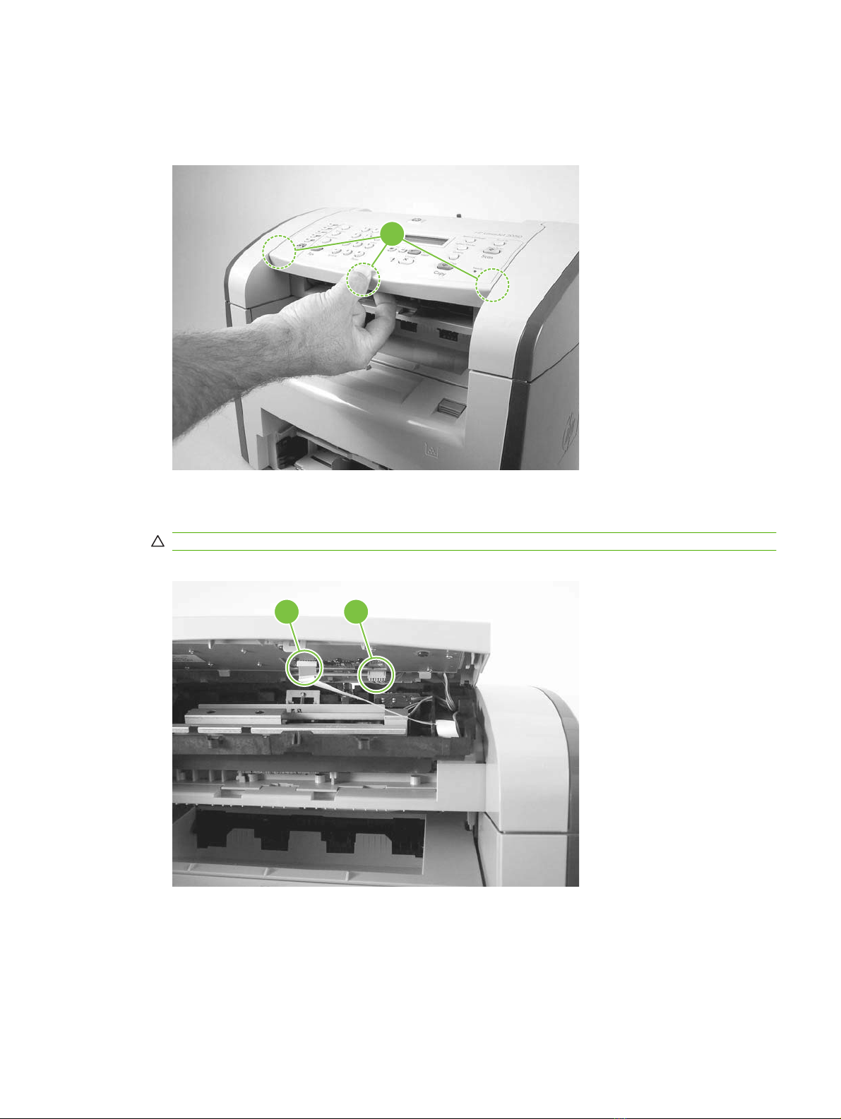
Top cover, control panel
1. Carefully release three locking tabs, one at the front and one on each side (callout 1).
Figure 6-11 Removing the top cover, control panel (1 of 3)
2. Slightly raise the top cover. Then disconnect one FFC (callout 2) and one wire-harness connector
(callout 3).
1
CAUTION: Do not bend or fold the FFCs during the removal or reinstallation process.
Figure 6-12 Removing the top cover, control panel (2 of 3)
2 3
ENWW Scanner assemblies 79
Page 94

3. Slightly open the ADF assembly, and then push the top cover toward the back of the product to
release the three rear locking tabs. Remove the top cover.
Figure 6-13 Removing the top cover, control panel (3 of 3)
NOTE: You must release the wire harness from two retainers on the top cover.
80 Chapter 6 Removal and replacement ENWW
Page 95

Control-panel assembly
CAUTION: The control panel is an ESD-sensitive component.
1. Remove the control-panel top cover. See Top cover, control panel on page 79.
2. Remove three screws (callout 1).
Figure 6-14 Removing the control-panel assembly (1 of 2)
1
3. Rotate the control-panel button assembly away from the control-panel cover and remove it.
Figure 6-15 Removing the control-panel assembly (2 of 2)
ENWW Scanner assemblies 81
Page 96

Media lever and media-lever torsion spring
1. Remove the control-panel top cover. See Top cover, control panel on page 79.
2. Carefully dislodge and remove the media-lever torsion spring.
Figure 6-16 Removing the media lever and media-lever torsion spring
82 Chapter 6 Removal and replacement ENWW
Page 97

Separation-pad assembly
1. Remove the control-panel top cover. See Top cover, control panel on page 79.
2. Remove five screws (callout 1) and the sheet-metal plate.
CAUTION: Do not touch the grey separation pad. Skin oils and fingerprints on the separation
pad might cause paper-feed problems.
Press down on the plate as the screws are removed. Four compression springs are under the plate.
The separation-pad assembly also has one compression spring attached to the shield. Be careful
not to lose any springs when you remove the shield.
NOTE: The separation-pad set and the separation-pad assembly are two different assemblies.
The separation-pad set consists of the pad, clear plastic sheet, and the pad cover. The separationpad set is a user-replaceable assembly.
The separation-pad assembly consists of the separation lever, tension spring, feed arm, and the
components of the separation-pad set. The separation-pad assembly is not a user-replaceable
assembly.
Only trained service personnel should attempt to replace the separation-pad assembly.
Figure 6-17 Removing the separation-pad assembly (1 of 3)
ENWW Scanner assemblies 83
Page 98

3. Rotate the separation-pad assembly up until the keyed hinges can clear the hinge retainers.
Figure 6-18 Removing the separation-pad assembly (2 of 3)
4. Remove the separation-pad assembly.
Figure 6-19 Removing the separation-pad assembly (3 of 3)
84 Chapter 6 Removal and replacement ENWW
Page 99

Scanner assembly
1. Rotate the ADF input tray assembly toward the front of the product, and then lift it up and off of the
product.
Figure 6-20 Removing the scanner assembly (1 of 14)
2. Rotate the ADF output bin up and then squeeze the locking tabs until the they clear the mounting
holes in the scanner assembly.
Figure 6-21 Removing the scanner assembly (2 of 14)
ENWW Scanner assemblies 85
Page 100

3. Remove the right-side cover-mounting screw (callout 1).
Figure 6-22 Removing the scanner assembly (3 of 14)
4. Release the back of the cover.
Figure 6-23 Removing the scanner assembly (4 of 14)
86 Chapter 6 Removal and replacement ENWW
 Loading...