

Page 1
LASERJET PRO 500 COLOR MFP
Troubleshooting Manual
M570
Page 2

HP LaserJet Enterprise 500 color MFP
M575 Printers
Troubleshooting Manual
Page 3

Copyright and License
Trademark Credits
© 2012 Copyright Hewlett-Packard
Development Company, L.P.
Reproduction, adaptation, or translation
without prior written permission is
prohibited, except as allowed under the
copyright laws.
The information contained herein is subject
to change without notice.
The only warranties for HP products and
services are set forth in the express warranty
statements accompanying such products and
services. Nothing herein should be
construed as constituting an additional
warranty. HP shall not be liable for technical
or editorial errors or omissions contained
herein.
Edition 1, 11/2012
Part number: CZ271-91021
Bluetooth is a trademark owned by its
proprietor and used by Hewlett-Packard
Company under license.
Microsoft®, Windows®, Windows® XP,
and Windows Vista® are U.S. registered
trademarks of Microsoft Corporation.
Page 4

Conventions used in this guide
TIP: Tips provide helpful hints or shortcuts.
NOTE: Notes provide important information to explain a concept or to complete a task.
CAUTION: Cautions indicate procedures that you should follow to avoid losing data or damaging
the product.
WARNING! Warnings alert you to specific procedures that you should follow to avoid personal
injury, catastrophic loss of data, or extensive damage to the product.
ENWW iii
Page 5

Table of contents
1 Theory of operation .......................................................................................................... 1
Basic operation ........................................................................................................................ 2
Sequence of operation ............................................................................................... 3
Formatter-control system ............................................................................................................ 4
Sleep delay .............................................................................................................. 4
Input/output ............................................................................................................. 4
CPU ........................................................................................................................ 5
Memory ................................................................................................................... 5
Firmware ................................................................................................... 5
Nonvolatile memory ................................................................................... 5
PJL overview ............................................................................................................. 5
PML ......................................................................................................................... 5
Control panel ........................................................................................................... 6
USB flash drive ......................................................................................................... 6
Engine-control system ................................................................................................................ 7
DC controller ............................................................................................................ 8
Solenoids .................................................................................................. 8
Clutches .................................................................................................... 9
Switches ................................................................................................... 9
Sensors ................................................................................................... 10
Motors and fans ....................................................................................... 11
High-voltage power supply ....................................................................................... 12
Low-voltage power supply ........................................................................................ 14
Overcurrent/overvoltage protection ............................................................ 15
Safety ..................................................................................................... 16
Voltage detection ..................................................................................... 16
Sleep (powersave) mode ........................................................................... 16
Power supply voltage detection .................................................................. 17
Low-voltage power supply failure ............................................................... 17
Power Off condition ................................................................................................ 17
Auto on/Auto off mode ............................................................................................ 17
Fuser (fixing) control ................................................................................................ 19
ENWW v
Page 6

Fuser (fixing) temperature-control circuit ...................................................... 20
Fuser (fixing) over-temperature protection .................................................... 20
Fuser (fixing)-failure detection .................................................................... 21
Laser/scanner system ............................................................................................................. 23
Image formation system .......................................................................................................... 25
Image formation process .......................................................................................... 26
Step 1: Pre-exposure ................................................................................. 27
Step 2: Primary charging .......................................................................... 27
Step 3: Laser-beam exposure ..................................................................... 28
Step 4: Development ................................................................................ 28
Step 5: Primary transfer ............................................................................ 29
Step 6: Secondary transfer ........................................................................ 29
Step 7: Separation ................................................................................... 30
Step 8: Fusing ......................................................................................... 30
Step 9: ITB cleaning ................................................................................. 31
Step 10: Drum cleaning ............................................................................ 31
Toner cartridge ....................................................................................................... 31
Developing roller engagement and disengagement ..................................................... 33
Intermediate transfer belt (ITB) unit ............................................................................. 35
Primary-transfer-roller engagement and disengagement ................................. 36
ITB cleaning ............................................................................................ 38
Calibration ............................................................................................................. 39
Color misregistration control ...................................................................... 39
Image stabilization control ........................................................................ 40
Pickup, feed, and delivery system ............................................................................................. 41
Pickup-and-feed unit ................................................................................................ 44
Tray pickup ............................................................................................. 45
Tray-presence detection .............................................................. 46
Tray lift operation ...................................................................... 46
paper-presence detection ........................................................... 48
Multifeed prevention .................................................................. 48
Multipurpose tray pickup ........................................................................... 49
Paper feed .............................................................................................. 50
Skew-feed prevention ................................................................. 51
OHT detection .......................................................................... 51
Fusing and delivery unit ........................................................................................... 52
Loop control ............................................................................................ 52
Pressure-roller pressurization control ........................................................... 54
Duplexing unit ........................................................................................................ 55
Duplexing reverse and feed control ............................................................ 56
Duplex pickup operation ........................................................................... 56
vi ENWW
Page 7

Jam detection ........................................................................................................................ 57
Optional paper feeder ............................................................................................................ 59
Paper-feeder pickup and feed operation .................................................................... 61
Paper size detection and presence detection .............................................................. 62
Paper feeder lift operation ........................................................................................ 64
Paper feeder presence detection ............................................................................... 65
Paper-feeder multiple feed prevention ........................................................................ 65
Paper feeder jam detection ....................................................................................... 67
Scanning/image capture system .............................................................................................. 68
Scanner power-on sequence of events ....................................................................... 68
Copy or scan sequence of events .............................................................................. 69
Fax functions and operation .................................................................................................... 70
Computer and network security features ..................................................................... 70
PSTN operation ...................................................................................................... 70
Receive faxes when you hear fax tones ...................................................................... 70
Distinctive ring function ............................................................................................ 71
Use fax with voice over IP services ............................................................................ 71
The fax subsystem ................................................................................................... 72
Fax card in the fax subsystem ................................................................................... 72
Safety isolation ........................................................................................ 72
Safety-protection circuitry .......................................................................... 72
Data path ................................................................................................ 73
Hook state ............................................................................................... 73
Downstream device detection .................................................................... 74
Hook switch control .................................................................................. 74
Ring detect .............................................................................................. 74
Line current control ................................................................................... 74
Billing- (metering-) tone filters ..................................................................... 74
Fax page storage in flash memory ............................................................................ 74
Stored fax pages ...................................................................................... 75
Advantages of flash memory storage .......................................................... 75
2 Solve problems ............................................................................................................... 77
Solve problems checklist ......................................................................................................... 78
Menu map ............................................................................................................................ 80
Troubleshooting process .......................................................................................................... 81
Pre-troubleshooting checklist ..................................................................................... 81
Determine the problem source ................................................................................... 83
Power subsystem ..................................................................................................... 84
Power-on checks ...................................................................................... 84
Control-panel checks ............................................................................................... 84
ENWW vii
Page 8

Tools for troubleshooting ......................................................................................................... 86
Component diagnostics ............................................................................................ 86
LED diagnostics ........................................................................................ 86
Network LEDs ........................................................................... 86
Control panel LEDs .................................................................... 86
Engine diagnostics ................................................................................... 87
Engine test ................................................................................ 87
Diagrams ............................................................................................................... 88
Block diagrams ........................................................................................ 88
Plug/jack locations ................................................................................... 90
Location of connectors .............................................................................. 91
DC controller PCA ..................................................................... 91
Locations of major components .................................................................. 93
Base product ............................................................................ 93
1 x 500 paper feeder ................................................................ 99
General timing chart ............................................................................... 100
General circuit diagrams ......................................................................... 101
Use HP Device Toolbox (Windows) ......................................................................... 103
Internal print-quality test pages ................................................................................ 104
Clean the paper path ............................................................................. 104
Print the configuration page ..................................................................... 104
Print-quality troubleshooting tools ............................................................................ 104
Repetitive image defect ruler .................................................................... 104
Control panel menus .............................................................................................. 106
Setup Menu ........................................................................................... 106
HP Web Services .................................................................... 106
Reports menu .......................................................................... 107
Self Diagnostics menu .............................................................. 108
Fax Setup menu ...................................................................... 108
System Setup menu .................................................................. 111
Service menu .......................................................................... 115
Network Setup menu ............................................................... 117
Quick Forms menu .................................................................. 118
Function specific menus ........................................................................... 119
USB Flash Drive ...................................................................... 119
Fax Menu ............................................................................... 119
Copy Menu ............................................................................ 122
Scan Menu ............................................................................. 123
Apps ..................................................................................... 123
Interpret control-panel messages ............................................................................. 124
Control panel message types ................................................................... 124
viii ENWW
Page 9

Control panel messages .......................................................................... 124
49 Error, Turn off then on ......................................................... 124
50.x Fuser Error ...................................................................... 124
51.XX Error ............................................................................ 124
54.XX Error ............................................................................ 125
55.X Error .............................................................................. 125
57 Fan Error, Turn off then on ................................................... 125
59.X Error .............................................................................. 126
79 Error Turn off then on .......................................................... 126
Black Cartridge Low ................................................................ 126
Black Very Low ....................................................................... 126
Cleaning ................................................................................ 127
Communication error. .............................................................. 127
Device error, press OK ............................................................ 127
Document feeder door is open. Canceled fax. ............................ 128
Door open .............................................................................. 128
Fax is busy. Canceled send. ..................................................... 128
Fax is busy. Redial pending. ..................................................... 128
Fax receive error. .................................................................... 129
Fax Send error. ....................................................................... 129
Fax storage is full. Canceling the fax receive. ............................. 130
Fax storage is full. Canceling the fax receive. ............................. 130
Fax storage is full. Canceling the fax send. ................................. 130
Genuine HP supply installed ..................................................... 130
Incompatible <color> ............................................................... 131
Install <color> cartridge ........................................................... 131
Invalid driver Press [OK] .......................................................... 131
Jam in Tray 1, Clear jam and then press OK .............................. 131
Load tray 1 Press [OK] for available media ................................ 131
Load Tray 1 <TYPE> <SIZE>, Press OK to use available media ..... 132
Load Tray 1, <PLAIN> <SIZE> / Cleaning mode, OK to start ....... 132
Load Tray <X>: [Type], [Size] ................................................... 132
Manual Duplex Load Tray 1, Press OK ...................................... 132
Manual feed <SIZE> <TYPE>, Press OK to use available media .... 132
Memory is low. Press OK. ........................................................ 133
Misprint, Press OK ................................................................... 133
No dial tone. .......................................................................... 133
No fax answer. Canceled send. ................................................ 134
No fax answer. Redial pending. ............................................... 134
No fax detected. ..................................................................... 134
Print failure, press OK. If error repeats, turn off then on. ............... 135
ENWW ix
Page 10

Remove shipping lock from <color> cartridge ............................. 135
Replace [color] ....................................................................... 135
Unexpected size in tray 1 Load <size> Press [OK] ...................... 135
Unsupported <color> Press [OK] to continue ............................... 136
Used <color> cartridge is installed Press [OK] to continue ............ 136
Event-log messages ............................................................................................... 137
Print the event log ................................................................................... 137
Show an event log ................................................................................. 137
Event log messages ................................................................................ 137
Clear jams .......................................................................................................................... 140
Jam locations ........................................................................................................ 140
Clear jams in the document feeder .......................................................................... 141
Clear jams in the output bin area ............................................................................ 143
Clear jams in Tray 1 .............................................................................................. 144
Clear jams in Tray 2 .............................................................................................. 146
Clear jams in the right door .................................................................................... 147
Clear jams in optional Tray 3 ................................................................................. 151
Clear jams in the lower right door (Tray 3) ............................................................... 152
Paper feeds incorrectly or becomes jammed ............................................................................ 153
The product does not pick up paper ........................................................................ 153
The product picks up multiple sheets of paper ........................................................... 153
The document feeder jams, skews, or picks up multiple sheets of paper ....................... 154
Prevent paper jams from the paper trays .................................................................. 154
Solve image quality problems ................................................................................................ 155
Image defects table ............................................................................................... 155
Clean the product ................................................................................................................ 161
Clean the pickup and separation rollers ................................................................... 161
Clean the paper path ............................................................................................ 161
Clean the scanner glass strip and platen .................................................................. 161
Clean the document feeder pickup rollers and separation pad .................................... 162
Clean the touchscreen ........................................................................................... 163
Solve performance problems ................................................................................................. 164
Factors affecting print performance ......................................................................... 164
Print speeds ........................................................................................... 165
The product does not print or it prints slowly ............................................................. 165
The product does not print ....................................................................... 165
The product prints slowly ......................................................................... 166
Solve connectivity problems ................................................................................................... 167
Solve direct-connect problems ................................................................................. 167
Solve network problems ......................................................................................... 167
Poor physical connection ......................................................................... 167
x ENWW
Page 11

The computer is using the incorrect IP address for the product ...................... 167
The computer is unable to communicate with the product ............................ 168
The product is using incorrect link and duplex settings for the network .......... 168
New software programs might be causing compatibility problems ................ 168
The computer or workstation might be set up incorrectly .............................. 168
The product is disabled, or other network settings are incorrect .................... 168
Solve wireless network problems ............................................................................. 169
Wireless connectivity checklist ................................................................. 169
The control panel displays the message: The wireless feature on this product
has been turned off ................................................................................ 170
The product does not print after the wireless configuration completes ............ 170
The product does not print, and the computer has a third-party firewall
installed ................................................................................................ 170
The wireless connection does not work after moving the wireless router or
product ................................................................................................. 170
Cannot connect more computers to the wireless product .............................. 170
The wireless product loses communication when connected to a VPN ........... 171
The network does not appear in the wireless networks list ........................... 171
The wireless network is not functioning ...................................................... 171
Service mode functions ......................................................................................................... 172
Service menu ........................................................................................................ 172
Service menu settings .............................................................................. 172
Restore the factory-set defaults ................................................................. 172
Secondary service menu ........................................................................................ 173
Open the secondary service menu ............................................................ 173
Secondary service menu structure ............................................................. 173
Product resets ....................................................................................................... 174
NVRAM initialization .............................................................................. 174
Super NVRAM initialization ..................................................................... 175
Solve fax problems ............................................................................................................... 176
Checklist for solving fax problems ........................................................................... 176
Perform a fax diagnostic test ................................................................................... 177
Fax trace report .................................................................................................... 178
Fax error report printing ......................................................................................... 178
Print all fax reports ................................................................................. 178
Print individual fax reports ....................................................................... 178
Set the fax error report ............................................................................ 179
Set the fax-error-correction mode ............................................................................. 179
Change the fax speed ........................................................................................... 179
Solve problems sending faxes ................................................................................. 180
An error message displays on the control panel ......................................... 180
ENWW xi
Page 12

The Communication error. message appears .............................. 180
No dial tone. .......................................................................... 181
The Fax is busy. message appears ............................................ 181
The No fax answer. message appears ....................................... 182
Document feeder paper jam ..................................................... 182
The Fax storage is full. message appears ................................... 183
Scanner error ......................................................................... 183
The control panel displays a Ready message with no attempt to send the fax . 183
The control panel displays the message "Storing page 1" and does not
progress beyond that message ................................................................. 184
Faxes can be received, but not sent .......................................................... 184
Product is password protected ................................................................. 184
Unable to use fax functions from the control panel ...................................... 184
Unable to use speed dials ....................................................................... 185
Unable to use group dials ....................................................................... 185
Receive a recorded error message from the phone company when trying to
send a fax ............................................................................................. 185
Unable to send a fax when a phone is connected to the product .................. 186
Solve problems receiving faxes ............................................................................... 186
The fax does not respond ........................................................................ 186
The fax has a dedicated phone line ........................................... 186
An answering machine is connected to the product ..................... 187
The Answer Mode setting is set to the Manual setting ................... 187
Voice mail is available on the fax line ........................................ 188
The product is connected to a DSL phone service ........................ 188
The product uses a fax over IP or VoIP phone service ................... 188
An error message displays on the control panel ......................................... 189
The No fax detected. message displays ..................................... 189
The Communication error. message appears .............................. 189
The Fax storage is full. message appears ................................... 190
The Fax is busy. message appears ............................................ 190
A fax is received but does not print .......................................................... 191
The Private Receive feature is on ............................................... 191
Sender receives a busy signal .................................................................. 191
A handset is connected to the product ........................................ 191
A phone line splitter is being used ............................................. 191
No dial tone .......................................................................................... 191
Cannot send or receive a fax on a PBX line ............................................... 191
Solve general fax problems .................................................................................... 192
Faxes are sending slowly ........................................................................ 192
Fax quality is poor ................................................................................. 193
xii ENWW
Page 13

Fax cuts off or prints on two pages ........................................................... 193
Solve email problems ........................................................................................................... 195
Cannot connect to the email server .......................................................................... 195
The email failed .................................................................................................... 195
Unable to scan ..................................................................................................... 195
Product upgrades ................................................................................................................. 196
Manually upgrade the firmware .............................................................................. 196
Set the product to automatically upgrade the firmware ............................................... 196
Appendix A Service and support ..................................................................................... 197
Hewlett-Packard limited warranty statement ............................................................................. 198
HP's Premium Protection Warranty: LaserJet toner cartridge limited warranty statement ................. 200
HP policy on non-HP supplies ................................................................................................ 201
HP anticounterfeit Web site ................................................................................................... 202
Data stored on the toner cartridge .......................................................................................... 203
End User License Agreement .................................................................................................. 204
OpenSSL ............................................................................................................................. 207
Customer self-repair warranty service ..................................................................................... 208
Customer support ................................................................................................................. 209
Repack the product .............................................................................................................. 210
Prepare the product for shipping ............................................................................. 210
Repack the product ............................................................................................... 214
Appendix B Product specifications ................................................................................... 215
Physical specifications .......................................................................................................... 216
Power consumption, electrical specifications, and acoustic emissions .......................................... 216
Environmental specifications .................................................................................................. 216
Appendix C Regulatory information ................................................................................. 217
FCC regulations ................................................................................................................... 218
Environmental product stewardship program ........................................................................... 219
Protecting the environment ...................................................................................... 219
Ozone production ................................................................................................. 219
Power consumption ............................................................................................... 219
Toner consumption ................................................................................................ 219
Paper use ............................................................................................................. 219
Plastics ................................................................................................................. 219
HP LaserJet print supplies ....................................................................................... 220
Return and recycling instructions ............................................................................. 220
United States and Puerto Rico .................................................................. 220
ENWW xiii
Page 14

Multiple returns (more than one cartridge) .................................. 220
Single returns .......................................................................... 220
Shipping ................................................................................ 220
Non-U.S. returns .................................................................................... 221
Paper .................................................................................................................. 221
Material restrictions ............................................................................................... 221
Disposal of waste equipment by users ...................................................................... 222
Electronic hardware recycling ................................................................................. 222
Chemical substances ............................................................................................. 222
Material Safety Data Sheet (MSDS) ......................................................................... 222
For more information ............................................................................................. 222
Declaration of conformity ...................................................................................................... 224
Declaration of conformity (wireless models) ............................................................................. 226
Certificate of Volatility .......................................................................................................... 228
Safety statements ................................................................................................................. 230
Laser safety .......................................................................................................... 230
Canadian DOC regulations .................................................................................... 230
VCCI statement (Japan) .......................................................................................... 230
Power cord instructions .......................................................................................... 230
Power cord statement (Japan) ................................................................................. 230
EMC statement (China) .......................................................................................... 231
EMC statement (Korea) .......................................................................................... 231
EMI statement (Taiwan) .......................................................................................... 231
Laser statement for Finland ..................................................................................... 231
GS statement (Germany) ........................................................................................ 233
Substances Table (China) ....................................................................................... 233
Restriction on Hazardous Substances statement (Turkey) ............................................. 233
Restriction on Hazardous Substances statement (Ukraine) ........................................... 233
Additional statements for telecom (fax) products ....................................................................... 234
EU Statement for Telecom Operation ....................................................................... 234
New Zealand Telecom Statements ........................................................................... 234
Additional FCC statement for telecom products (US) .................................................. 234
Telephone Consumer Protection Act (US) .................................................................. 235
Industry Canada CS-03 requirements ...................................................................... 235
Vietnam Telecom wired/wireless marking for ICTQC Type approved products ............. 236
Additional statements for wireless products .............................................................................. 237
FCC compliance statement—United States ................................................................ 237
Australia statement ................................................................................................ 237
Brazil ANATEL statement ........................................................................................ 237
Canadian statements ............................................................................................. 237
Products with 5 GHz Operation Industry of Canada .................................................. 238
xiv ENWW
Page 15

Exposure to Radio Frequency Radiation (Canada) ..................................................... 238
European Union regulatory notice ........................................................................... 238
Notice for use in France ......................................................................................... 238
Notice for use in Russia ......................................................................................... 238
Mexico statement .................................................................................................. 239
Taiwan statement .................................................................................................. 239
Korean statement .................................................................................................. 239
Vietnam Telecom wired/wireless marking for ICTQC Type approved products ............. 239
Index ............................................................................................................................... 241
ENWW xv
Page 16

List of tables
Table 1-1 Sequence of operation ............................................................................................................ 3
Table 1-2 Solenoids .............................................................................................................................. 8
Table 1-3 Switches ................................................................................................................................ 9
Table 1-4 Sensors ............................................................................................................................... 10
Table 1-5 Motors ................................................................................................................................ 11
Table 1-6 Fans ................................................................................................................................... 12
Table 1-7 High-voltage power supply circuits ......................................................................................... 13
Table 1-8 Converted DC voltages ......................................................................................................... 15
Table 1-9 Fuser (fixing) components ...................................................................................................... 19
Table 1-10 Image formation process ..................................................................................................... 26
Table 1-11 Primary-transfer-roller engagement states ............................................................................... 36
Table 1-12 Image-stabilization controls .................................................................................................. 40
Table 1-13 Switches and sensors for the pickup, feed, and delivery system ................................................ 41
Table 1-14 Motors and solenoids for the pickup, feed, and delivery system ............................................... 42
Table 1-15 Jams that the product detects ............................................................................................... 57
Table 1-16 Electrical components for the paper feeder ............................................................................ 60
Table 1-17 Paper size detection ........................................................................................................... 63
Table 2-1 Control-panel 2ndary Service test access buttons ...................................................................... 85
Table 2-2 Plug/jack locations ............................................................................................................... 90
Table 2-3 DC controller connectors ....................................................................................................... 91
Table 2-4 Component locations ............................................................................................................ 97
Table 2-5 Component locations (1 x 500-sheet paper feeder) .................................................................. 99
Table 2-6 Repetitive defects ................................................................................................................ 105
Table 2-7 Event-log messages ............................................................................................................. 137
Table 2-8 Event-log-only messages ...................................................................................................... 138
Table 2-9 Image defects table ............................................................................................................ 155
Table 2-10 Control-panel 2ndary Service te
Table 2-11 Secondary Service menu ................................................................................................... 173
Table B-1 Physical specifications ......................................................................................................... 216
Table B-2 Operating-environment specifications .................................................................................... 216
st access buttons .................................................................. 173
ENWW xvii
Page 17

List of figures
Figure 1-1 Relationship between the main product systems ......................................................................... 2
Figure 1-2 Engine-control system ............................................................................................................. 7
Figure 1-3 DC controller block diagram ................................................................................................... 8
Figure 1-4 High-voltage power supply circuits ........................................................................................ 13
Figure 1-5 Low-voltage power-supply circuit ........................................................................................... 14
Figure 1-6 Fuser (fixing) components ..................................................................................................... 19
Figure 1-7 Fuser temperature-control circuit ............................................................................................ 20
Figure 1-8 Laser/scanner system ........................................................................................................... 23
Figure 1-9 Image formation system ........................................................................................................ 25
Figure 1-10 Image formation process .................................................................................................... 26
Figure 1-11 Pre-exposure ..................................................................................................................... 27
Figure 1-12 Primary charging ............................................................................................................... 27
Figure 1-13 Laser-beam exposure ......................................................................................................... 28
Figure 1-14 Development ..................................................................................................................... 28
Figure 1-15 Primary transfer ................................................................................................................. 29
Figure 1-16 Secondary transfer ............................................................................................................ 29
Figure 1-17 Separation ....................................................................................................................... 30
Figure 1-18 Fusing .............................................................................................................................. 30
Figure 1-19 ITB cleaning ...................................................................................................................... 31
Figure 1-20 Drum cleaning .................................................................................................................. 31
Figure 1-21 Toner-cartridge system ....................................................................................................... 32
Figure 1-22 Developing-roller engagement and disengagement control ..................................................... 33
Figure 1-23 ITB unit ............................................................................................................................. 35
Figure 1-24 Three states of primary-transfer-roller engagement and disengagement ..................................... 36
Figure 1-25 ITB cleaning process .......................................................................................................... 38
Figure 1-26 Toner patterns for calibration .............................................................................................. 39
Figure 1-27 Switches and sensors for the pickup, feed, and de
Figure 1-28 Motors and solenoids for the pickup, feed, and delivery system .............................................. 42
Figure 1-29 Three main units of the pickup, feed, and delivery system ....................................................... 43
Figure 1-30 Pickup-and-feed unit ........................................................................................................... 44
Figure 1-31 Tray-pickup mechanism ...................................................................................................... 45
Figure 1-32 Tray presence sensor ......................................................................................................... 46
livery system ............................................... 41
ENWW xix
Page 18

Figure 1-33 Tray lift mechanism ............................................................................................................ 47
Figure 1-34 Paper-level-detection mechanism .......................................................................................... 48
Figure 1-35 Multifeed prevention .......................................................................................................... 48
Figure 1-36 Multipurpose tray pickup mechanism ................................................................................... 49
Figure 1-37 Paper-feed mechanism ....................................................................................................... 50
Figure 1-38 Skew-feed prevention ......................................................................................................... 51
Figure 1-39 Fuser and delivery unit ....................................................................................................... 52
Figure 1-40 Loop-control mechanism ..................................................................................................... 53
Figure 1-41 Pressure-roller pressurization control .................................................................................... 54
Figure 1-42 Duplexing unit ................................................................................................................... 55
Figure 1-43 Jam detection sensors ........................................................................................................ 57
Figure 1-44 Optional paper feeder ....................................................................................................... 59
Figure 1-45 Signals for the paper feeder ............................................................................................... 60
Figure 1-46 Paper-feeder pickup and feed operation ............................................................................... 61
Figure 1-47 Paper size detection .......................................................................................................... 62
Figure 1-48 Paper-feeder lift ................................................................................................................. 64
Figure 1-49 Paper-feeder multiple feed prevention .................................................................................. 65
Figure 1-50 Jam detection .................................................................................................................... 67
Figure 2-1 Control-panel 2ndary Service test access buttons ..................................................................... 85
Figure 2-2 Engine test button access ...................................................................................................... 87
Figure 2-3 Block diagram (product base) ............................................................................................... 88
Figure 2-4 DC controller PCA ............................................................................................................... 91
Figure 2-5 Component locations (1 of 5) ................................................................................................ 93
Figure 2-6 Component locations (2 of 5) ................................................................................................ 94
Figure 2-7 Component locations (3 of 5) ................................................................................................ 95
Figure 2-8 Component locations (4 of 5) ................................................................................................ 96
Figure 2-9 Component locations (5
Figure 2-10 1 x 500-sheet paper feeder ................................................................................................ 99
Figure 2-11 Timing diagram ............................................................................................................... 100
Figure 2-12 Circuit diagram — product base (1 of 2) ............................................................................ 101
Figure 2-13 Circuit diagram — product base (2 of 2) ............................................................................ 102
Figure 2-14 Control-panel 2ndary Service test access buttons ................................................................. 173
Figure A-1 Prepare the product for shipping (1 of 3) ............................................................................. 211
Figure A-2 Prepare the product for shipping (2 of 3) ............................................................................. 212
Figure A-3 Prepare the product for shipping (3 of 3) ............................................................................. 213
Figure C-1 Certificate of Volatility (1 of 2) ............................................................................................ 228
Figure C-2 Certificate of Volatility (2 of 2) ............................................................................................ 229
of 5) ................................................................................................ 97
xx ENWW
Page 19

1 Theory of operation
Basic operation
●
Formatter-control system
●
Engine-control system
●
Laser/scanner system
●
Image formation system
●
Pickup, feed, and delivery system
●
Jam detection
●
Optional paper feeder
●
Scanning/image capture system
●
Fax functions and operation
●
ENWW 1
Page 20
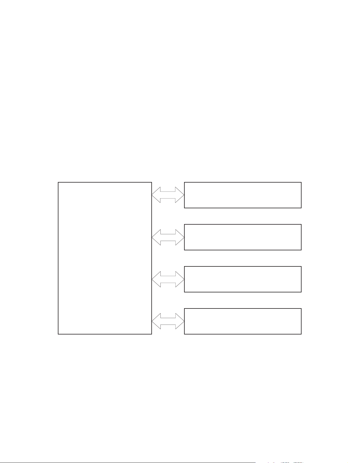
Basic operation
The product routes all high-level processes through the formatter, which stores font information,
processes the print image, and communicates with the host computer.
The basic product operation comprises the following systems:
The engine-control system, which includes the power supply and the DC controller printed circuit
●
assembly (PCA)
The laser/scanner system, which forms the latent image on the photosensitive drum
●
The image-formation system, which transfers a toner image onto the paper
●
The media feed system, which uses a system of rollers and belts to transport the paper through the
●
product
Option (optional paper feeder)
●
Figure 1-1 Relationship between the main product systems
Laser/scanner system
Engine control system
Image-formation system
Media-feed system
Option
2 Chapter 1 Theory of operation ENWW
Page 21

Sequence of operation
The DC controller PCA controls the operating sequence, as described in the following table.
NOTE: The terms fusing and fixing are synonymous.
Table 1-1 Sequence of operation
Period Duration Description
Waiting From the time the power is turned on,
the door is closed, or when the product
exits Sleep mode until the product has
fully initialized and is ready for printing
Standby From the end of the waiting sequence or
the last rotation until the formatter
receives a print command or until the
product is turned off
Initial rotation From the time the formatter receives a
print command until the paper enters the
paper path
Heats the fuser sleeve
●
Pressurizes the fuser pressure roller
●
Detects the toner cartridges
●
Detects the home position for the
●
primary transfer roller and the
developing unit
Cleans the secondary transfer roller
●
Is fully initialized and is ready to
●
print.
Enters Sleep mode after the
●
specified length of time
Calibrates if it is time for an
●
automatic calibration
Activates the high-voltage power
●
supply
Prepares each laser/scanner unit
●
Warms the fuser to the correct
●
temperature
ENWW
Printing From the time the first sheet of paper
enters the paper path until the last sheet
has passed through the fuser
Last rotation From the time the last sheet of paper
exits the fuser until the motors stop
rotating
Forms the image on the
●
photosensitive drums
Transfers the toner to the paper
●
Fuses the toner image onto the
●
paper
Performs calibration after a
●
specified number of pages
Moves the last printed sheet into
●
the output bin
Stops each laser/scanner unit
●
Discharges the bias from the high-
●
voltage power supply
Basic operation
3
Page 22

Formatter-control system
The formatter is responsible for the following procedures:
Controlling sleep mode
●
Receiving and processing print data from the various product interfaces
●
Monitoring control panel functions and relaying product-status information (through the control
●
panel and the network or bidirectional interface)
Developing and coordinating data placement and timing with the DC controller PCA
●
Storing font information
●
Communicating with the host computer through the network or the bidirectional interface
●
The formatter receives a print job from the network or bidirectional interface and separates it into
image information and instructions that control the printing process. The DC controller PCA
synchronizes the image-formation system with the paper-input and -output systems, and then signals the
formatter to send the print-image data.
The formatter also provides the electrical interface and mounting locations for an additional DIMM.
Sleep delay
This feature conserves power after the product has been idle for an adjustable period of time. When
the product is in Sleep Delay, the control panel backlight is turned off, but the product retains all
settings, downloaded fonts, and macros. The default setting is for Sleep Delay to be enabled, and the
product enters Sleep Delay after a 15-minute idle time.
The product exits Sleep Delay and enters the warm-up cycle when any of the following events occur:
A print job, valid data, or a PML or PJL command is received
●
A control panel button is pressed
●
A cover is opened
●
A paper tray is opened
●
NOTE: Product error messages override the sleep function. The product enters Sleep Delay at the
appropriate time, but the error message continues to appear.
Input/output
The product has three I/O interfaces:
Hi-Speed USB 2.0
●
10/100/1000 Ethernet LAN connection
●
Easy-access USB printing (no computer required)
●
4 Chapter 1 Theory of operation ENWW
Page 23

CPU
The formatter incorporates an 800 MHz processor.
Memory
The random access memory (RAM) on the formatter printed circuit assembly (PCA) contains the page,
I/O buffers, and the font storage area. It stores printing and font information received from the host
system, and can also serve to temporarily store a full page of print-image data before the data is sent to
the print engine.
NOTE: If the product encounters a problem when managing available memory, a clearable warning
message appears on the control panel display.
Firmware
The firmware is contained on the formatter. A remote firmware upgrade process is used to overwrite
and upgrade the firmware on the formatter.
Nonvolatile memory
The product uses nonvolatile random access memory (NVRAM) to store device and user configuration
settings. The contents of NVRAM are retained when the product is turned off or disconnected.
PJL overview
The printer job language (PJL) is an integral part of configuration, in addition to the standard printer
command language (PCL). With standard cabling, the product can use PJL to perform a variety of
functions.
Two-way communication with the host computer through a network connection or a USB
●
connection. The product can inform the host about the control panel settings which can be
changed from the host.
Dynamic I/O switching. The product uses this switching to be configured with a host on each I/O.
●
The product can receive data from more than one I/O simultaneously, until the I/O buffer is full.
This can occur even when the product is offline.
Context-sensitive switching. The product can automatically recognize the personality (PS or PCL) of
●
each job and configure itself to serve that personality.
Isolation of print environment settings from one print job to the next. For example, if a print job is
●
sent to the product in landscape mode, the subsequent print jobs print in landscape mode only if
they are formatted for landscape printing.
PML
ENWW
The printer management language (PML) allows remote configuration and status read-back through the
I/O ports.
Formatter-control system
5
Page 24

Control panel
The control panel is a capacitive touchscreen and adjustable viewing angle.
The control panel has a diagnostic mode to allow testing of the touchscreen. The control panel does not
require calibration.
USB flash drive
The product features printing from a USB flash drive. The product prints the following file types from the
USB flash drive.
PDF
●
RGB JPEG
●
When a USB flash drive is inserted into the front of the product, the control panel will display the USB
Flash Drive menu. The files on the USB flash drive can be accessed from the control panel using the
touchscreen. Any RGB JPEG or PDF files on the USB flash drive can be printed directly from the product
control panel.
6 Chapter 1 Theory of operation ENWW
Page 25
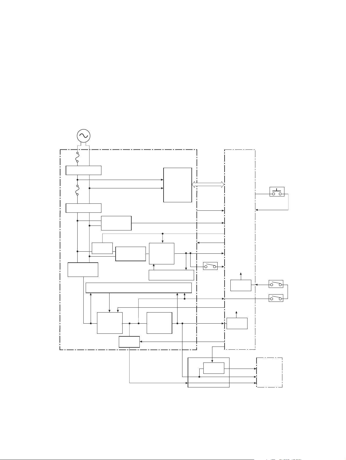
Engine-control system
The engine-control system receives commands from the formatter and interacts with the other main
systems to coordinate all product functions. The engine-control system consists of the following
components:
DC controller
●
High-voltage power supply
●
Low-voltage power supply
●
Figure 1-2 Engine-control system
AC input
Fuse
Noise filter
DC controller
Fuse
Noise filter
Zero crossing
Switch
Rectifying
circuit
+5V
generation
circuit
Low-voltage power supply
circuit
Rectifying
circuit
Protection circuit
Switch
Fusing control
+24V
generation
circuit
Protection circuit
+3.3V
generation
circuit
circuit
+5VB
ICB
PSTYP100
/ZEROX
24VRMT
+24VB
+24VA
SW3
+24VB
+5VA
PWRSAVE
+3.3VA
VC5VOFF
VC3VOFF
Switch
Switch
+3.3VC
Switch
+3.3VB
+3.3VA
+5VB
+5VD
Power switch
PWRSWON
SW1
+5VC
SW2
Formatter
ENWW
Engine-control system
7
Page 26
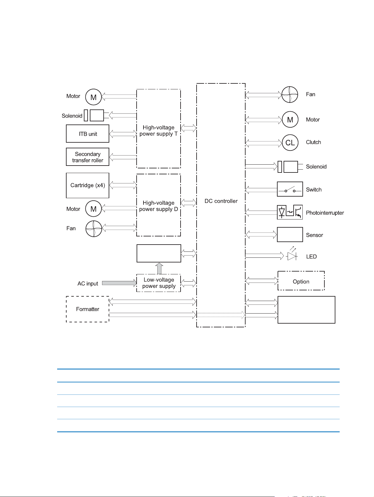
DC controller
The DC controller controls the operational sequence of the printer.
Figure 1-3 DC controller block diagram
Solenoids
Table 1-2 Solenoids
Component abbreviation Component name
SL1 Primary transfer roller disengagement solenoid
SL2 Duplex reverse solenoid
SL3 Multipurpose-tray pickup solenoid
SL4 Tray pickup solenoid
Fuser
Laser/scanner
8 Chapter 1 Theory of operation ENWW
Page 27

Clutches
Switches
Table 1-3 Switches
Component abbreviation Component name
CL1 Duplex re-pickup clutch
Component abbreviation Component name
SW1, SW2 5V interlock switch
SW3 24V interlock switch
SW4 Power switch
SW100 Test print switch
ENWW
Engine-control system
9
Page 28

Sensors
Table 1-4 Sensors
Component abbreviation Component name
SR1 Drum home position sensor 1
SR2 Drum home position sensor 2
SR3 Drum home position sensor 3
SR5 Fuser (fixing) delivery sensor
SR6 Delivery tray media full sensor
SR7 Fuser (fixing) pressure release sensor
SR8 TOP (top of page) sensor
SR9 Tray-media-stack surface sensor
SR11 Developing home position sensor
SR13 Tray presence sensor
SR14 Loop sensor 1
SR15 Loop sensor 2
SR17 Primary-transfer-roller disengagement sensor
SR20 Tray-media presence sensor
SR21 MP-tray-media-presence sensor
SR22 Duplex re-pickup sensor
OHT sensor (in)
OHT sensor (out)
RD sensor (front)
RD sensor (rear)
Environmental sensor (temperature and humidity)
Yellow toner-level sensor
Magenta toner-level sensor
Cyan toner-level sensor
Black toner-level sensor
Toner collection-box-full sensor
Fuser (fixing) home-position sensor
10 Chapter 1 Theory of operation ENWW
Page 29

Motors and fans
The product has 11 motors and three fans. The motors drive the components in the paper-feed and
image-formation systems. The fan motors cool the inside of the product.
Table 1-5 Motors
Abbreviation Name Purpose Type Failure detection
M2 Fuser (fixing) motor Drives the fuser (fixing)
roller, the delivery
roller, and the fuser
(fixing) pressure roller
M3 Drum motor 1 Drives the
photosensitive drum
(yellow/magenta),
developing unit
(yellow), and primary
charging roller
(yellow/magenta)
M4 Drum motor 2 Drives the
photosensitive drum
(cyan), developing unit
(magenta/cyan), and
primary charging roller
(cyan)
M5 Drum motor 3 Drives the
photosensitive drum
(black), developing unit
(black), and ITB drive
roller, and secondary
transfer roller
M7 Lifter motor Drives the lifter for the
tray
DC motor Yes
DC motor Yes
DC motor Yes
DC motor Yes
DC motor Yes
ENWW
M8 Cyan/black scanner
motor
M9 Yellow/magenta
scanner motor
M10 Developing
disengagement motor
M11 Duplex reverse motor Drives the duplex
Drives the scanner
mirror in the cyan/
black laser scanner
Drives the scanner
mirror in the yellow/
magenta laser scanner
Drives the developing
unit disengagement
reverse roller and
duplex feed roller
DC motor Yes
DC motor Yes
Stepping motor No
Stepping motor No
Engine-control system
11
Page 30

Table 1-5 Motors (continued)
Abbreviation Name Purpose Type Failure detection
M12 Residual toner-feed
motor
M13 Pickup motor Drives the tray pickup
Table 1-6 Fans
Abbreviation Name Cooling area Type Speed
FM1 Power supply fan Around the power
FM2 Cartridge fan Around the cartridges Intake Full/half
FM3 Delivery fan Around the delivery
High-voltage power supply
Drives the residual
toner feed screw
roller, MP tray pickup
roller, feed roller,
registration roller, and
re-pickup roller
supply unit
unit
DC motor Yes
Stepping motor No
Intake Full/half
Intake Full/half
The high-voltage power supply delivers the high-voltage biases to the following components used to
transfer toner during the image-formation process:
Primary-charging roller (in the cartridge)
●
Developing roller (in the cartridge)
●
12 Chapter 1 Theory of operation ENWW
Page 31

Primary-transfer roller
●
Secondary-transfer roller
●
Figure 1-4 High-voltage power supply circuits
Y
M
C
K
The high-voltage power supply contains several separate circuits.
Table 1-7 High-voltage power supply circuits
Circuit Description
Primary-charging-bias generation DC negative bias is applied to the surface of the photosensitive drum to prepare it
for image formation.
Developing-bias generation DC negative bias adheres the toner to each photosensitive drum during the image-
formation process.
Primary-transfer-bias generation DC positive bias transfers the latent toner image from each photosensitive drum
onto the ITB.
Secondary-transfer-bias generation Two DC biases, one positive and one negative, transfer the toner from the ITB onto
the paper.
ENWW
Engine-control system
13
Page 32

Low-voltage power supply
The low-voltage power-supply circuit converts the AC power from the wall receptacle into the DC
voltage that the product components use. The product has two low-voltage power-supplies for 110 Volt
or 220 Volt input.
Figure 1-5 Low-voltage power-supply circuit
Fuser control
circuit
The low-voltage power supply converts the AC power into three DC voltages, which it then subdivides,
as described in the following table.
14 Chapter 1 Theory of operation ENWW
Page 33

Table 1-8 Converted DC voltages
Main DC voltage Sub-voltage Behavior
+24V +24VA Stopped during Sleep (powersave)
mode
+24VB Interrupted when the front door or right
door open
Stopped during Sleep (powersave)
mode
+5V +5VA Constantly supplied
3.3V is supplied during Sleep mode 2
or Sleep mode 3
+5VB 3.3V is supplied during Sleep mode 2
Stopped during Sleep mode 3
Power for the formatter
+5VC 3.3V is supplied during Sleep mode 2
or Sleep mode 3
Interrupted when the front door or right
door open (SW1/SW2)
+5VD Stopped during Sleep mode
+3.3 V 3.3VA Constantly supplied
3.3VB Stopped only when the power is off
3.3VC Stopped during Sleep mode 2 or Sleep
24V Power Supply (24VRMT) signal: Controls supply or interruption of +24VA
●
5V Power supply (VC5VOFF) signal: Controls supply or interruption of +5VB
●
3V Power supply (VC3VOFF) signal: Controls supply or interruption of +3.3VB
●
Voltage conversion (PWRSAVE) signal: Converts output voltage of +5VA, +5VB and +5VC into
●
+3.3V
Overcurrent/overvoltage protection
Interrupted when the front door or right
door open (SW1/SW2)
Power for the formatter
mode 3
ENWW
The low-voltage power supply stops supplying the DC voltage to the product components whenever it
detects excessive current or abnormal voltage from the power source.
Engine-control system
15
Page 34

The low voltage power supply has a protective circuit against overcurrent and overvoltage to prevent
failures in the power supply circuit. If DC voltage is not being supplied from the low voltage power
supply, the protective function might be running. In this case, turn the power off and disconnect the
power cable. Do not connect and turn on the product until the root cause is found and corrected. In
additon, the low voltage power supply has two fuses (FU100/FU101) to protect against overcurrent. If
overcurrent flows into the AC line, the fuse blows to stop AC power.
Safety
For personal safety, the low-voltage power supply interrupts power to the fuser, the high-voltage power
supply, and the motors when the front door or right door open.
The product has AC power even when the power switch is turned off because the product uses a soft
power switch. Be sure to disconnect the power cable before disassembling the product.
Voltage detection
The printer detects the power supply voltage that is connected to the printer. The DC controller monitors
the input voltage from the power source so it can control the voltage to the fuser.
Sleep (powersave) mode
Sleep mode reduces the power consumption of the product. There are three sleep modes depending on
the power consumption. The DC controller stops or converts each power supply according to the sleep
mode:
Sleep mode 1: stops +24VA and +24VB
●
Sleep mode 2: stops +24VA, +24VB and +5VD. Converts +5VA and +5VC into +3.3V
●
Sleep mode 3: stops +24VA, +24VB, +5VB and +5VD. Converts +5VA and +5VC into +3.3V.
●
Power
consumption
Off Less than 0.5W Off Manually: press
Auto off Less than 1W Blinks at 3 second
Sleep Approximately 6W Blinks at 3 second
Status of power
button light
intervals
intervals
How to enable
mode
the power button
Automatically:
sleep timer
expires
Sleep timer
expires
Sleep timer
expires
How to disable
mode (put in
fully initialized
and ready to
print state)
Press the power
button
Printing or network
maintenance tasks
Printing or network
maintenance tasks
Relative time to
fully initialized
and ready to
print state
Longest
Longer than Sleep
mode
Shortest
16 Chapter 1 Theory of operation ENWW
Page 35

Power supply voltage detection
The product detects the power supply voltage that is connected to the product. The DC controller
monitors the POWER SUPPLY VOLTAGE (PSTYP100) signal and detects power supply voltage, whether
100V or 200V, to control the fusing operation properly.
Low-voltage power supply failure
The DC controller determines a low-voltage power supply failure and notifies the formatter when the
low-voltage power supply does not supply +24V.
Power Off condition
The DC controller brings the product to a power off condition by 24V POWER SUPPLY (24VRMT)
signal, 5V POWER SUPPLY (VC5VOFF) signal, 3V POWER SUPPLY (VC3VOFF) signal, and VOLTAGE
CONVERSION (PWRSAVE) signal.
The +5VA and +5VC signals which are converted into +3.3V and +3.3VA, are supplied under the
power off condition.
Auto on/Auto off mode
This feature conserves power after the product has been idle for an adjustable period of time. When
the product is in this mode, the control panel backlight is turned off, but the product retains all settings,
downloaded fonts, and macros. The setting is disabled by default. The product enters this mode after a
60-minute idle time or by touching the sleep button.
Power
consumption
Off Less than 0.5W Off Manually:
Status of
power
button light
How to
enable
mode
press the
power button
Automatically:
sleep timer
expires
How to
disable mode
(put in fully
initialized
and ready to
print state)
Press the power
button
Relative time
to fully
initialized
and ready to
print state
Longest
control panel
term
ENWW
Engine-control system
17
Page 36

Power
consumption
Status of
power
button light
How to
enable
mode
How to
disable mode
(put in fully
initialized
and ready to
print state)
Relative time
to fully
initialized
and ready to
print state
control panel
term
Auto off Less than 1W Blinks at 3
second intervals
Sleep (A1W) Approximately6WBlinks at 3
second intervals
Sleep timer
expires
Sleep timer
expires
Printing or
network
maintenance
tasks
Insert or remove
paper from the
ADF
Open or close
the scanner
Open the
cartridge door
Touch the
control panel
touchscreen
Press the power
button
Printing or
network
maintenance
tasks
Insert or remove
paper from the
ADF
Longer than
Sleep mode
Shortest All events
Network port
Open or close
the scanner
Open the
cartridge door
Touch the
control panel
touchscreen
Press the power
button
NOTE: Product error messages override the Sleep message. The product enters sleep mode at the
appropriate time, but the error message continues to appear.
18 Chapter 1 Theory of operation ENWW
Page 37

Fuser (fixing) control
The fuser-control circuit controls the fuser temperature. The product uses an on-demand fusing method.
Figure 1-6 Fuser (fixing) components
Fuser sleeve
Table 1-9 Fuser (fixing) components
Type of component Abbreviation Name Function
Fuser control
FUSER HEATING
CONTROL signal
FUSER TEMPERATURE signal
circuit
Fuser heater
safety circuit
Heaters H1 Fuser heater Heats the fuser sleeve.
Thermistors
(Contact type)
Thermoswitches
(Non-contact type)
TH1 Main thermistor The thermistor detects the center
temperature of the fuser sleeve.
TH2
TH3
TP1 For the fuser heater Controls the fuser-roller main
Sub thermistor Each thermistor detects the side
temperature of the fuser heater.
heater
ENWW
Engine-control system
19
Page 38

Fuser (fixing) temperature-control circuit
The temperatures of the two rollers in the fuser fluctuate according to the stage of the printing process.
The DC controller sends commands to the fuser-control circuit to adjust temperatures.
Figure 1-7 Fuser temperature-control circuit
Fuser
Fuser sleeve unit
Fuser heater
control circuit
Fuser heater safety
circuit
Fuser
Fuser heater safety circuit
Fuser (fixing) over-temperature protection
To protect the fuser from excessive temperatures, the product has four layers of protective functions. If
one function fails, the subsequent functions should detect the problem.
DC controller: When a thermistor or thermopile detects a temperature above a certain threshold,
●
the DC controller interrupts power to the specific heater. Following are the thresholds for each
component:
TH1: 230° C (446° F) or higher
◦
TH2: 285° C (545° F) or higher
◦
Fuser control circuit
Fuser
TH3: 285° C (545° F) or higher
◦
Fuser (fixing)-heater safety circuit: If the DC controller fails to interrupt the power to the
●
heaters at the prescribed temperatures, the fuser-heater safety circuit deactivates the triac-drive
20 Chapter 1 Theory of operation ENWW
Page 39

circuit and releases the relay, which causes the heaters to stop at slightly higher temperature
thresholds.
TH2: 290° C (554° F) or higher
◦
TH3: 290° C (554° F) or higher
◦
Current-detection protection circuit: If current flowing in each triac exceeds a specific value,
●
the current-detection protection circuit deactivates the triac-drive circuit and releases the relay,
which interrupts the power supply to the heaters.
Thermoswitch: If the temperature in the heaters is abnormally high, and the temperature in the
●
thermoswitches exceeds a specified value, the contact to the thermoswitch breaks. Breaking this
contact deactivates the triac-drive circuit and releases the relay, which interrupts the power supply
to the heaters. Following are the thresholds for each thermoswitch:
TP1: 270° C (518° F) or higher
◦
NOTE: When the thermoswitches reach this temperature, the temperature on the fuser rollers is about
320° C (608° F).
Fuser (fixing)-failure detection
When the DC controller detects any of the following conditions, it determines that the fuser has failed.
The DC controller then interrupts power to the fuser heaters and notifies the formatter.
Abnormally high temperatures: Temperatures are too high for any of the following
●
components, at any time:
TH1: 230° C (446° F) or higher
◦
TH2: 285° C (545° F) or higher
◦
TH3: 285° C (545° F) or higher
◦
Abnormally low temperatures: Temperatures are too low at any of the following
●
components after the product has initialized.
TH1: 120° C (248° F) or lower
◦
TP2 or TP3: 100° C (212° F) or lower
◦
Or, the temperature drops in either of the thermopiles (TP2 and TP3) by 30° C (86° F) or more
within a specified length of time.
Abnormal temperature rise: The DC controller determines an abnormal temperature rise if
●
the detected temperature of TH1 does not rise 2° C within a specified time period after the fuser
(fixing) motor is turned on, or if the detected temperature of the thermistors does not rise to a
specified temperature for a specified time after the fuser (fixing) motor is turned on.
ENWW
Engine-control system
21
Page 40

Thermistor open: The DC controller determines a thermistor open if:
●
The detected temperature of TH1 is kept at 12° C (53° F) or lower for a specified time after
◦
the fuser (fixing) motor is turned on.
The detected temperature of TH2 is kept at 4° C (39° F) or lower for a specified time.
◦
The detected temperature of TH3 is kept at 4° C (39° F) or lower for a specified time.
◦
Drive-circuit failure: The DC controller determines a drive-circuit failure:
●
If the detected power supply frequency is out of a specified range when the printer is turned
◦
on or during the standby period
If the current detection circuit detects an out of specified current value
◦
Fuser (fixing) discrepancy: The DC controller determines a fuser type mismatch when it
●
detects an unexpected fuser (fixing) unit presence signal. The product has two fusers for 110 V or
220 V input power.
22 Chapter 1 Theory of operation ENWW
Page 41

Laser/scanner system
The laser/scanner system forms the latent electrostatic image on the photosensitive drums according to
the VIDEO signals sent from the formatter. The product has two laser/scanners: one for yellow and
magenta and the other for cyan and black.
The formatter sends the DC controller instructions for the image of the page to be printed. The DC
controller signals the lasers to emit light, and the laser beams pass through lenses and onto the scanner
mirror, which rotates at a constant speed. The mirror reflects the beam onto the photosensitive drum in
the pattern necessary for the image, exposing the surface of the drum so it can receive toner.
Figure 1-8 Laser/scanner system
ENWW
Laser/scanner system
23
Page 42

The DC controller determines that a laser/scanner has failed when any of the following conditions
occurs:
Laser failure: The detected laser intensity does not match a specified value when the product
●
initializes.
Beam-detect (BD) failure: The BD interval is outside a specified range during printing.
●
Scanner-motor failure: The scanner motor does not reach a specified rotation speed within a
●
certain time after it begins rotating.
24 Chapter 1 Theory of operation ENWW
Page 43

Image formation system
The image-formation system creates the printed image on the paper. The system consists of the laser/
scanners, toner cartridges, imaging drums, ITB, and fuser.
Figure 1-9 Image formation system
Y
M
Fuser
C
Laser/scanner
K
Laser/scanner
ENWW
Image formation system
25
Page 44

Image formation process
The image-formation system consists of ten steps divided into six functional blocks.
Figure 1-10 Image formation process
Y
M
Fusing
Fuser
C
K
Table 1-10 Image formation process
Functional block Steps Description
Latent image formation 1. Pre-exposure
2. Primary charging
3. Laser-beam exposure
Development 4. Development Toner adheres to the electrostatic latent
Transfer 5. Primary transfer
6. Secondary transfer
7. Separation
Fusing 8. Fusing The toner fuses to the paper to make a
ITB cleaning 9. ITB cleaning Residual toner is removed from the ITB.
Drum cleaning 10. Drum cleaning Residual toner is removed from the
An invisible latent image forms on the
surface of the photosensitive drums.
image on the photosensitive drums.
The toner image transfers to the ITB and
subsequently to the paper.
permanent image.
photosensitive drums.
26 Chapter 1 Theory of operation ENWW
Page 45

Step 1: Pre-exposure
Light from the pre-exposure LED strikes the surface of the photosensitive drum to remove any residual
electrical charges from the drum surface.
Figure 1-11 Pre-exposure
Step 2: Primary charging
The primary-charging roller contacts the photosensitive drum and charges the drum with negative
potential.
Figure 1-12 Primary charging
ENWW
Image formation system
27
Page 46

Step 3: Laser-beam exposure
The laser beam strikes the surface of the photosensitive drum in the areas where the image will form.
The negative charge neutralizes in those areas, which are then ready to accept toner.
Figure 1-13 Laser-beam exposure
Step 4: Development
Toner acquires a negative charge as the developing cylinder contacts the developing blade. Because
the negatively charged surface of the photosensitive drums have been neutralized where they have
been struck by the laser beam, the toner adheres to those areas on the drums. The latent image
becomes visible on the surface of each drum.
Figure 1-14 Development
28 Chapter 1 Theory of operation ENWW
Page 47

Step 5: Primary transfer
The positively charged primary-transfer rollers contact the ITB, giving the ITB a positive charge. The ITB
attracts the negatively charged toner from the surface of each photosensitive drum, and the complete
toner image transfers onto the ITB, beginning with yellow, followed by magenta, cyan, and black.
Figure 1-15 Primary transfer
Step 6: Secondary transfer
The paper acquires a positive charge from the secondary-transfer roller, and so it attracts the negatively
charged toner from the surface of the ITB. The complete toner image transfers onto the paper.
Figure 1-16 Secondary transfer
ENWW
Image formation system
29
Page 48

Step 7: Separation
The stiffness of the paper causes it to separate from the ITB as the ITB bends. The static-charge
eliminator removes excess charge from the paper to ensure that the toner fuses correctly.
Figure 1-17 Separation
Step 8: Fusing
To create the permanent image, the paper passes through heated, pressurized rollers to melt the toner
onto the page.
Figure 1-18 Fusing
Fuser sleeve
Fuser heater
30 Chapter 1 Theory of operation ENWW
Page 49

Step 9: ITB cleaning
The cleaning blade scrapes the residual toner off the surface of the ITB. The residual-toner-feed screw
deposits residual toner in the toner collection box.
Figure 1-19 ITB cleaning
Step 10: Drum cleaning
Inside the toner cartridge, the cleaning blade removes residual toner from the surface of the drum to
prepare it for the next image. The waste toner falls into the hopper in the print cartridge.
Figure 1-20 Drum cleaning
Toner cartridge
The product has four toner cartridges, one for each color. Each toner cartridge contains a reservoir of
toner and the following components:
Photosensitive drum
●
Developing roller
●
Primary-charging roller
●
ENWW
Image formation system
31
Page 50

The DC controller rotates the drum motor to drive the photosensitive drum, developing roller, and the
primary-charging roller.
Figure 1-21 Toner-cartridge system
The DC controller rotates the drum motor to drive the photosensitive drum, developing unit, and primary
charging roller.
The memory tag is a non-volatile memory chip that stores information about the usage for the toner
cartridge.
32 Chapter 1 Theory of operation ENWW
Page 51

The DC controller notifies the formatter of an error if any of the following conditions exist:
The memory tag fails to either read to or write from the DC controller.
●
The RD sensors detect a missing or incorrectly installed toner cartridge.
●
The accumulated print time reaches a specified time period or the cartridge runs out of toner.
●
The toner level in any of the toner cartridges drops below a certain level.
●
Developing roller engagement and disengagement
The product can print in full-color mode or in black-only mode. To print in black-only mode, the product
disengages the developing rollers in the cyan, magenta, and yellow toner cartridges. This maximizes
the life of the cartridges.
Figure 1-22 Developing-roller engagement and disengagement control
Four developing units engaged
Y
Y
M
M
C
C
K
K
Only the Bk developing unit engaged
Y
Y
M
Four developing units disengaged
Y
Y
M
M
C
C
K
K
M
C
C
K
K
ENWW
Image formation system
33
Page 52

The DC controller rotates the developing disengagement motor and changes the direction of the cam
according to the instructions from the formatter for each print job.
When the product is turned on and at the end of each print job, all four of the developing rollers
disengage from the photosensitive drums. If the next print job is full-color mode, each of the developing
rollers engage. If the next print job is black-only mode, only the black developing roller engages.
If the DC controller does not detect any output from the developing home-position sensor, it determines
that the developing-disengagement motor has failed.
34 Chapter 1 Theory of operation ENWW
Page 53

Intermediate transfer belt (ITB) unit
The ITB unit accepts the toner images from the photosensitive drums and transfers the completed image
to the paper. The ITB unit has these main components:
ITB
●
ITB drive roller
●
ITB-driven roller
●
Primary-transfer rollers
●
ITB cleaner
●
The ITB motor drives the ITB drive roller, which rotates the ITB. The motion of the ITB causes the primary
transfer rollers to rotate. The ITB cleaner cleans the ITB surface.
Figure 1-23 ITB unit
ENWW
C
K
M
Y
Image formation system
35
Page 54

Primary-transfer-roller engagement and disengagement
Depending on the requirements of the print job, the primary-transfer rollers engage with the ITB so it
can receive toner from the photosensitive drums.
Figure 1-24 Three states of primary-transfer-roller engagement and disengagement
Fuser motor
Four colors are disengaged
Y
FUSER MOTOR CONTROL
Y
Four colors are engaged
Y
Y
Only black is engaged
Y
Y
M
M
M
M
C
C
K
K
M
C
C
K
K
M
C
C
K
K
Table 1-11 Primary-transfer-roller engagement states
Roller state Product state
All rollers disengaged The home position for the ITB unit
All rollers engaged The state for a full-color print job
Black roller engaged The state for a black-only print job
36 Chapter 1 Theory of operation ENWW
Page 55

The primary-transfer-roller disengagement motor rotates or reverses to place the primary-transfer-roller
disengagement cam into one of three positions. The cam causes the transfer-roller slide plate to move to
the right or left. This movement causes the primary-transfer rollers to move up to engage the ITB with the
photosensitive drum or down to disengage it.
If the DC controller does not receive the expected signal from the ITB home-position sensor when the
primary-transfer-roller engages or disengages, but the primary-transfer-roller disengagement motor is
rotating, the DC controller determines that the primary-transfer-disengagement mechanism has failed,
and notifies the formatter.
ENWW
Image formation system
37
Page 56

ITB cleaning
The cleaning blade in the ITB cleaner scrapes the residual toner off the ITB surface. The drum motor
(M5) drives the residual toner feed screw. The screw feeds the residual toner to the residual toner feed
unit. The residual toner feed motor (M12) drives the residual toner feed screw. The residual toner feed
screw deposits the residual toner in the toner collection box. The DC control detects whether the toner
collection box is full, using the toner collection-box-full sensor, and then notifies the formatter.
Figure 1-25 ITB cleaning process
38 Chapter 1 Theory of operation ENWW
Page 57

Calibration
The product calibrates itself to maintain excellent print quality. Calibration corrects color-misregistration
and color-density variation.
During calibration, the product places a specific pattern of toner on the surface of the ITB. Sensors at
the end of the ITB read the toner pattern to determine if adjustments are necessary.
Figure 1-26 Toner patterns for calibration
Color misregistration control
Internal variations in the laser/scanners can cause the toner images to become misaligned. The colormisregistration control corrects the following problems:
Horizontal scanning start position
●
Horizontal scanning magnification
●
Vertical scanning start position
●
The calibration occurs when any of the following occurs:
A cartridge is replaced.
●
The temperature of the sub thermistor is 50 C (122 F) or lower when the product recovers from
●
sleep mode after a specific number of pages print.
A specified number of pages have printed.
●
The formatter sends a command.
●
The user requests a calibration by using the control panel menus.
●
ENWW
Image formation system
39
Page 58

If data from the color-misregistration and image-density sensors is outside a specified range when the
product is turned on or when it is beginning the calibration sequence, the DC controller determines that
these sensors have failed, and it notifies the formatter.
Image stabilization control
Environmental changes or deterioration of the photosensitive drums and toner can cause variations in
the image density. The image-stabilization control reduces these fluctuations. There are three kinds of
image stabilization controls.
The formatter control is performed by the formatter.
Table 1-12 Image-stabilization controls
Image stabilization control Description
Environment change control The environment change control calibrates each high-voltage bias to obtain an
appropriate image according to the environment changes. The DC controller
determines the environment where the product is installed based on the surrounding
temperature and humidity data from the environment sensor, controls, and related
biases. This control occurs under the following circumstances:
The toner cartridge is replaced.
●
The DC controller notifies the formatter when it encounters a communication error
with the environmental sensor.
Image density control (DMAX) This control corrects variations in image density related to deterioration of the
photosensitive drum or the toner. The DC controller adjusts the high-voltage biases
to correct the problem under the following conditions:
The sub thermistor detects a temperature that is too low when the product is
●
turned on.
After the print operation is completed for a specific period of the time.
●
A toner cartridge is replaced.
●
The ITB is replaced.
●
A specified number of pages have printed.
●
The formatter sends a command.
●
The environment is relatively charged.
●
Image halftone control (DHALF) The image halftone control is performed by the formatter. The DC controller
measures the halftone pattern according to the command from the formatter. The
formatter performs this control to calibrate the halftone, based on the halftonedensity measurements, under the following conditions:
The formatter sends a command.
●
The DMAX is completed.
●
The DC controller determines an RD sensor failure and notifies the formatter if it detects an out-ofspecified-data value from the RD sensor when the product is turned on or when the color misregistration
control starts.
40 Chapter 1 Theory of operation ENWW
Page 59

Pickup, feed, and delivery system
The pickup, feed, and delivery system uses a series of rollers to move the paper through the product.
Figure 1-27 Switches and sensors for the pickup, feed, and delivery system
Y
M
C
K
Table 1-13 Switches and sensors for the pickup, feed, and delivery system
Abbreviation Component
SR5 Fuser (fixing) delivery sensor
SR6 Delivery tray media full sensor
SR7 Fuser (fixing) pressure release sensor
SR8 TOP (top of page) sensor
SR9 Tray-media stack-surface sensor
SR13 Tray presence sensor
ENWW
SR14 Loop sensor 1
SR15 Loop sensor 2
SR20 Tray media-presence sensor
Pickup, feed, and delivery system
41
Page 60

Table 1-13 Switches and sensors for the pickup, feed, and delivery system (continued)
Abbreviation Component
SR21 MP tray media-presence sensor
SR22 Duplex re-pickup sensor (duplex models only)
Figure 1-28 Motors and solenoids for the pickup, feed, and delivery system
Y
M
C
K
Table 1-14 Motors and solenoids for the pickup, feed, and delivery system
Abbreviation Component
M2 Fuser (fixing) motor
M5 Drum motor 3
M7 Lifter motor
M11 Duplex reverse motor (duplex models only)
42 Chapter 1 Theory of operation ENWW
Page 61

Table 1-14 Motors and solenoids for the pickup, feed, and delivery system (continued)
Abbreviation Component
M13 Pickup motor
CL1 Duplex re-pickup clutch (duplex models only)
SL2 Duplex reverse solenoid (duplex models only)
SL3 Multipurpose tray pickup solenoid
SL4 Tray pickup solenoid
Figure 1-29 Three main units of the pickup, feed, and delivery system
Fuser/delivery block
Duplex block
Y
M
C
K
ENWW
Pickup, feed, and delivery system
43
Page 62

Pickup-and-feed unit
The pickup-and-feed unit picks an individual sheet of paper from the multipurpose tray or the cassettes,
carries it through the secondary-transfer unit, and feeds it into the fuser.
Figure 1-30 Pickup-and-feed unit
Y
M
C
K
44 Chapter 1 Theory of operation ENWW
Page 63

Tray pickup
The sequence of steps for the tray pickup operation is the following:
1. When the product starts or the tray closes, the lifting mechanism lifts the paper stack so it is ready.
2. After receiving a print command from the formatter, the DC controller rotates the pickup motor,
3. The DC controller drives the tray pickup solenoid, which rotates the tray pickup cam. As the
Figure 1-31 Tray-pickup mechanism
which causes the tray pickup roller, tray feed roller, and tray separation roller to rotate.
pickup cam rotates, the pickup arm moves down, and the tray pickup roller touches the surface of
the paper stack. The tray pickup roller then picks up one sheet of paper.
Tray
Tray
Tray
NOTE: The lift-up operation lifts the lifting plate to keep the stack surface of the media at a pickup
position. The lifting spring helps support the lifting plate depending on the media size and amount.
ENWW
Pickup, feed, and delivery system
45
Page 64

Tray-presence detection
The tray presence sensor is in the lifter drive unit. The sensor detects the tray-presence sensor flag and
determines whether the tray is installed correctly.
Figure 1-32 Tray presence sensor
Tray
Tray lift operation
The DC controller rotates the lifter motor (M7) and moves the lifter rack until the tray media stack
surface sensor (SR9) detects it. The lifter lifts, and the lifting plate moves up to the position where the
media can be picked up. The lift operation is performed by monitoring the media stack surface sensor
when the printer is turned on, when the tray is installed, or as needed during a print operation.
If the paper-stack surface sensor does not detect the paper within a specified time after the lifter motor
begins rotating, the DC controller notifies the formatter that the lifter motor has failed.
Tray
46 Chapter 1 Theory of operation ENWW
Page 65

The DC controller lowers the lifting plate when no printing occurs to prevent media damage and pickup
failure. If a print operation does not occur for a specified time, the DC controller reverses the lifter
motor and moves the lifter rack until the tray media-stack surface sensor stops detecting it.
Figure 1-33 Tray lift mechanism
Tray
Tray
ENWW
Pickup, feed, and delivery system
47
Page 66

paper-presence detection
The media presence sensor detects whether paper is in the .
Figure 1-34 Paper-level-detection mechanism
Tray
Tray
Multifeed prevention
In the , a separation roller prevents multiple sheets of paper from entering the paper path. The pickup
roller drives the separation roller through a sheet of paper.
Tray
The low friction force between the sheets weakens the driving force from the pickup roller. Because
some braking force is applied to the separation roller, the weak rotational force of the pickup roller is
not enough to rotate the separation roller. Therefore, the separation roller holds back any multiple-fed
sheets, and one sheet of media is fed into the printer.
Figure 1-35 Multifeed prevention
Cassette pickup
roller
Cassette
separation
roller
Normal feed
Lifting plate
Media
Separation roller does not rotate
Multiple feed
48 Chapter 1 Theory of operation ENWW
Page 67

Multipurpose tray pickup
The multipurpose tray (MP) paper-presence sensor detects whether paper is in the tray. If no paper is
present, the DC controller notifies the formatter. Printing does not occur until paper is in the tray.
The sequence of steps for the multipurpose tray pickup operation as follows:
1. After receiving a print command from the formatter, the DC controller reverses the pickup motor,
which causes the multipurpose tray separation roller to rotate.
2. The DC controller turns on the multipurpose tray pickup solenoid (SL3), causing the multipurpose
tray pickup roller to rotate.
3. The multipurpose tray separation roller isolates a single sheet of paper in case more than one
sheet was picked. The single sheet of paper feeds into the product.
The MP-tray media-presence sensor (SR21) detects whether the media is present in the MP tray. No
printing occurs if no media is loaded.
Figure 1-36 Multipurpose tray pickup mechanism
ENWW
Pickup, feed, and delivery system
49
Page 68

Paper feed
After the pickup operation, the paper feeds through the product and into the fuser.
1. The paper passes through the feed rollers. The registration shutter aligns the paper correctly to
2. The DC controller detects the leading edge of paper by the Top sensor (SR8) and controls the
3. The DC controller detects whether or not the media is overhead transparency, using the OHT
4. The toner image on the ITB transfers onto the media, which feeds to the fuser.
Figure 1-37 Paper-feed mechanism
prevent skewed printing.
rotational speed of the pickup motor to align with the leading edge of image on the ITB.
sensor.
50 Chapter 1 Theory of operation ENWW
Page 69

Skew-feed prevention
The product can straighten the paper without slowing the feed operation.
1. As the paper enters the paper path, the leading edge strikes the registration shutter, which
straightens the paper. The paper does not pass through the shutter.
2. The feed rollers keep pushing the paper, which creates a force on the leading edge against the
registration shutter.
3. When the force is great enough, the registration shutter opens and the paper passes through.
Figure 1-38 Skew-feed prevention
1
2
3
OHT detection
The OHT sensor detects overhead transparencies. The OHT sensor is a transmission sensor that uses an
LED. The DC controller determines a media mismatch and notifies the formatter when the media type
differs from the media type detected by the OHT sensor. The DC controller turns the LED in the OHT
ENWW
Pickup, feed, and delivery system
51
Page 70

sensor on and off during the wait or initial rotation period. If the intensity of the light does not match the
specified value, the DC controller determines that the OHT sensor has failed.
Fusing and delivery unit
The fusing and delivery unit fuses the toner onto the paper and delivers the printed page into the output
bin. The following controls ensure optimum print quality:
Loop control
●
Pressure roller pressurization/depressurization control
●
A sensor detects when the output bin is full, and the DC controller notifies the formatter.
Figure 1-39 Fuser and delivery unit
Fuser/delivery block
Loop control
The loop control monitors the tension of the paper between the secondary-transfer roller and the fuser.
If the fuser rollers rotate more slowly than the secondary transfer rollers, the paper warp increases
●
and an image defect or paper crease occurs.
Y
M
C
K
If the fuser rollers rotate faster than the secondary transfer rollers, the paper warp decreases and
●
the toner image fails to transfer to the paper correctly, causing color misregistration.
52 Chapter 1 Theory of operation ENWW
Page 71

To prevent these problems, the loop sensors, which are located between the secondary transfer rollers
and the fuser rollers, detect whether the paper is sagging or is too taut. The DC controller adjusts the
speed of the fuser motor.
Figure 1-40 Loop-control mechanism
ENWW
Pickup, feed, and delivery system
53
Page 72

Pressure-roller pressurization control
To prevent excessive wear on the pressure roller and help with jam-clearing procedures, the pressure
roller pressurizes only during printing and standby. The DC controller reverses the fuser motor. The
fuser motor rotates the fuser pressure-release cam.
Figure 1-41 Pressure-roller pressurization control
FUSER MOTOR CONTROL
Fuser motor
FUSER PRESSURE RELEASE signal
Fuser pressure release cam
Fuser sleeve
The pressure roller depressurizes under the following conditions:
The product is turned off with the on/off switch
●
Any failure occurs other than a fuser pressure-release mechanism failure
●
During powersave mode
●
When a paper jam is detected
●
If the DC controller does not sense the fuser pressure-release sensor for a specified period after it
reverses the fuser motor, it notifies the formatter that a fuser pressure-release mechanism failure has
occurred.
NOTE: The fuser remains pressurized if the power is interrupted when the power cord is removed or
the surge protector is turned off, or if the fuser is removed without turning off the product.
54 Chapter 1 Theory of operation ENWW
Page 73

Duplexing unit
The duplexing unit reverses the paper and feeds it through the paper path to print the second side. The
duplexing unit consists of the following components:
Duplexing-reverse unit: Installed on top of the product
●
Duplexing-feed unit: Along the right side
●
The DC controller controls the operational sequence of the duplex block. The DC controller drives each
load, such as motors, solenoid, and clutch, depending on the duplex-reverse unit and duplex-feed unit
controls.
Figure 1-42 Duplexing unit
ENWW
Pickup, feed, and delivery system
55
Page 74

Duplexing reverse and feed control
The duplexing reverse procedure pulls the paper into the duplexing unit after it exits the fuser. The
duplexing feed procedure moves the paper through the duplexer so it can enter the product paper path
to print the second side of the page.
1. After the first side has printed, the duplexing flapper solenoid opens, which creates a paper path
into the duplexing-reverse unit.
2. After the paper has fully entered the duplexing-reverse unit, the duplexing-reverse motor reverses
and directs the paper into the duplexing-feed unit.
3. The duplexing re-pickup motor and duplexing feed motor move the paper into the duplexing re-
pickup unit.
4. To align the paper with the toner image on the ITB, the duplexing re-pickup motor stops and the
paper pauses.
5. The paper re-enters the paper path, and the second side prints.
Duplex pickup operation
The product has the following two duplex-media-feed modes depending on the media sizes:
One-sheet mode: Prints one sheet that is printed on two sides in one duplex print operation
●
Two-sheet mode: Prints two sheets that are printed on two-sides in one duplex print operation
●
(maximum paper size is A4)
The formatter specifies the duplex-media-feed mode.
56 Chapter 1 Theory of operation ENWW
Page 75

Jam detection
The product uses the following sensors to detect the paper as it moves through the paper path and to
report to the DC controller if the paper has jammed.
Fuser output sensor (SR5)
●
Registration sensor (SR8)
●
Fuser loop 1 (SR14)
●
Fuser loop 2 (SR15)
●
Duplexer refeed (SR22)
●
Figure 1-43 Jam detection sensors
Y
M
C
K
The product determines that a jam has occurred if one of these sensors detects paper at an
inappropriate time. The DC controller stops the print operation and notifies the formatter.
Table 1-15 Jams that the product detects
Jam Description
Pickup delay jam 1 pickup: The TOP sensor does not detect the leading edge of the paper within a specified
period after the pickup solenoid has turned on.
ENWW
Multipurpose tray pickup: The TOP sensor does not detect the leading edge of the paper
within a specified period after the multipurpose tray solenoid has turned on.
Pickup stationary jam The TOP sensor does not detect the trailing edge of the paper within a specified time from
when it detects the leading edge.
Jam detection
57
Page 76

Table 1-15 Jams that the product detects (continued)
Jam Description
Fuser delivery delay jam The fuser delivery paper-feed sensor does not detect the leading edge of the paper within a
specified period after the TOP sensor detects the leading edge.
Fuser delivery stationary jam The fuser delivery paper-feed sensor does not detect the trailing edge of the paper within a
specified period after it detects the leading edge.
Wrapping jam After detecting the leading edge of the paper, the fuser delivery paper-feed sensor detects the
absence of paper, and it has not yet detected the trailing edge.
Residual paper jam One of the following sensors detects paper presence during the initialization sequence:
Fuser delivery paper-feed sensor
●
TOP sensor
●
Loop sensor 1
●
Loop sensor 2
●
Duplex re-feed
●
Door open jam A door is opened while paper is moving through the product.
Duplexing re-pickup jam 1 The duplex re-pickup sensor does not detect the leading edge of the paper within a specified
period after the media reverse operation starts in the duplex-reverse unit.
Duplexing re-pickup jam 2 The TOP sensor does not detect the leading edge of the paper within a specified period after
the paper is re-picked.
After a jam, some sheets of paper might remain inside the product. If the DC controller detects residual
paper after a door closes or after the product is turned on, the product automatically clears itself of
those residual sheets.
58 Chapter 1 Theory of operation ENWW
Page 77

Optional paper feeder
The 1x500-sheet paper feeder is optionally installed underneath the product. The paper feeder picks up
the print media and feeds it to the printer.
NOTE: These optional trays are
Figure 1-44 Optional paper feeder
Y
M
not
C
identical to the main (Tray 2).
K
ENWW
The paper-deck drivers contain a microcomputer and control the paper feeder. The paper-deck drivers
receive commands from the DC controller. If the DC controller is unable to communicate with a paperdeck driver, it notifies the formatter that the optional paper feeders are not connected correctly.
Optional paper feeder
59
Page 78

Figure 1-45 Signals for the paper feeder
The input trays contain several motors, solenoids, sensors, and switches, as described in the following
table.
Table 1-16 Electrical components for the paper feeder
Component
type
Motors M1 Paper feeder motor
Solenoids SL1 Paper feeder pickup solenoid
Sensors SR1 Tray 3 installed sensor
Switches SW1 Paper feeder media-size switch
Abbreviation Component name
M2 Paper feeder lift motor
SR2 Tray 3 stack surface sensor 2
SR3 Tray 3 paper present sensor
SR4 Tray 3 feed sensor
SW2 Paper-feeder door switch
60 Chapter 1 Theory of operation ENWW
Page 79

Paper-feeder pickup and feed operation
The paper feeder picks up one sheet from the paper-feeder and feeds it to the product.
Figure 1-46 Paper-feeder pickup and feed operation
ENWW
Optional paper feeder
61
Page 80

Paper size detection and presence detection
The paper-feeder media-size switch (SW1) detects the size of paper loaded in the paper-feeder . The
paper-feeder driver determines the media size by monitoring the combination of the switches.
Figure 1-47 Paper size detection
Tray
62 Chapter 1 Theory of operation ENWW
Page 81

Table 1-17 Paper size detection
Paper size Paper-feeder media-size switch settings
Top switch Center switch Bottom switch
Universal On On On
A5 On Off Off
B5 Off On On
Executive On Off On
Letter Off On Off
A4 Off Off On
Legal On On Off
No Off Off Off
The paper-feeder media size switch (SW1) detects whether the paper-feeder is installed correctly. The
paper-feeder driver determines if a is absent when all three switches are turned off. The paper-feeder
driver determines a presence when one of the switches is turned on.
ENWW
Optional paper feeder
63
Page 82

Paper feeder lift operation
The lift operation keeps the stack surface of paper at a specified height to maintain stable media
feeding. The paper-feeder driver controls the paper-feeder lifter motor (M2) and monitors the paperfeeder media stack surface sensors (SR1, SR2) to adjust the stack height when the printer is turned on,
when the printer recovers from sleep mode, when the paper-feeder is installed or as needed during a
print operation. The paper feeder has two paper-feeder media-stack surface sensors. The paper-feeder
media stack surface sensor 1 detects the stack height during a print operation. The paper-feeder mediastack surface sensor 2 detects the stack height when the printer is turned on, when the printer recovers
from sleep mode and when the paper-feeder is installed. The operational sequence of the lift operation
is as follows:
1. The paper-feeder driver rotates the paper-feeder lifter motor to lift the lifting plate.
2. The paper-feeder driver stops the paper-feeder lifter motor when the paper-feeder media-stack
surface sensor 2 detects the stack surface.
3. The paper-feeder driver rotates the lifter motor again when paper-feeder media stack surface 1
detects that the media surface is lowered during a print operation.
Figure 1-48 Paper-feeder lift
The paper-feeder driver notifies the formatter if either of the paper-feeder media-stack surface sensors
fails to detect the stack surface within a specified period from when a lift-up operation starts.
64 Chapter 1 Theory of operation ENWW
Page 83

Paper feeder presence detection
The Tray 3 paper present (SR3) detects whether the paper is present in the paper-feeder .
Paper-feeder multiple feed prevention
The paper-feeder uses a separation roller to prevent multiple sheets of paper from entering the printer.
The separation roller prevents multiple feeds of paper by allowing the paper-feeder separation roller to
rotate in the same direction as the paper-feeder feed roller 1. The paper-feeder separation roller is
equipped with the torque limiter. If multiple sheets of paper are picked up, the torque limiter takes
control of the paper-feeder separation roller, and pushes the extra sheets back to the paper-feeder .
That way, only the top sheet is fed to the printer.
Figure 1-49 Paper-feeder multiple feed prevention
ENWW
No-load Rotational force for paper-feeder separation roller: Pushes
back the media into the paper-feeder
Rotational force for paper-feeder feed roller 1: Feeds media
into the printer
Optional paper feeder
65
Page 84

Normal feed Rotational force for paper-feeder separation roller: Pushes
back the media into the paper-feeder
Rotational force for paper-feeder feed roller 1: Feeds media
into the printer
Multiple-feed The low friction force between the sheets weakens the
rotational force from the paper-feeder feed roller 1.
The paper-feeder separation roller rotates by its own
rotational force and removes the extra sheet.
66 Chapter 1 Theory of operation ENWW
Page 85

Paper feeder jam detection
The paper feeder uses the Tray 3 feed (SR4) to detect the presence of paper and to check whether
paper has jammed.
Figure 1-50 Jam detection
Y
M
C
K
ENWW
The paper-feeder driver identifies a jam if the sensor detects paper at a specified timing stored in the
paper-feeder driver. The paper-feeder driver stops printing and notifies the formatter through the DC
controller of the jam. The paper feeder detects the following jams:
Pickup delay jam: The paper-feeder media-feed sensor does not detect the leading edge of media
●
within a specified period from when the paper-feeder pickup solenoid is turned on.
Pickup stationary jam: The paper-feeder media-feed sensor does not detect the trailing edge of
●
media within a specified time period from when the sensor detects the leading edge.
Optional paper feeder
67
Page 86

Scanning/image capture system
The flatbed image scanner captures an electronic image of the document on the glass. The scanner
does this by illuminating the document with LEDs (red, green, and blue) and capturing the image in the
image sensor to create an electronic format of the document. The flatbed scanner consists of three main
elements.
CIS scanner. The CIS (contact image sensor) scanner captures an image using the product's
●
optical path. Red, green, and blue LEDs sequentially illuminate a small strip of the document (often
called a raster line), and the optical system captures each color in a single row of CCD sensors
that cover the entire page width. Because only one color is captured for each line per exposure,
the three colors are recombined electronically to create the full color image. For monochromatic
scans or copies, all three LEDs are illuminated to create a white light for the scan so the raster line
can be captured in one exposure.
Mechanical carriage drive. The carriage drive moves the CIS scan head along the document
●
length to create the image. In this product, a small DC motor with an optical encoder creates this
motion. The speed of the carriage drive is proportional to the scan resolution (300 ppi is much
faster than 1200 ppi) and also proportional to the type of scan (color scans are three-times slower
than monochromatic scans). A 1200 ppi color scan moves so slowly that the product may appear
to not be working, whereas a monochromatic copy scan moves at 50 times that speed and will be
a little noisy.
Image processing system (formatter). The formatter processes the scanner data into either
●
a copy or a scan to the computer. For copies, the image data is sent directly to the product
without being transmitted to the computer. Depending on user selections for the copy settings, the
formatter enhances the scanner data significantly before sending it to the product. Image data is
captured at 300 ppi for copies and is user selectable for scans to the computer. Each pixel is
represented by 8 bits for each of the three colors (256 levels for each color), for a total of 24 bits
per pixel (24-bit color).
Scanner power-on sequence of events
When the product is turned on, it performs the following tests:
Motor test. The product moves the motor left and right to confirm operation. It reports a scanner
●
error 12 if no motion is detected in the motor encoder system.
Wall find. The scan carriage moves slowly to the left while watching an encoder on the carriage
●
motor to determine when the carriage has found the side wall or stop. This enables the product to
identify the document origin (position of the original). If the document origin cannot be located, a
default position is used instead.
LED check. The product moves the carriage to the white calibration label under the left side of
●
the flatbed image scanner, and it verifies that the minimum and maximum response is acceptable.
It reports a scanner error 14 if the response is unacceptable.
Home find. The scan carriage uses the optical scanner to find physical reference features that
●
relate to the document origin at the left side of the image glass. This process ensures accurate
location of the first document pixels so that the user documents will have an accurate placement of
68 Chapter 1 Theory of operation ENWW
Page 87

the image on scans and copies. It reports a scanner error 6 message if the reference features are
not found.
Calibration. This test, also known as scanner color calibration, enables the product to identify
●
the black and white on every pixel in the CCD. Calibration occurs in two major processes: a
broad (analog) adjustment of all pixels to bring them into the target output range, and a pixel-bypixel adjustment (digital) to fine tune the actual black and white response. The calibration process
occurs under the left side of flatbed image scanner where there is a special white calibration
label.
Calibration is the most important step in creating a high quality image. Calibration problems can
include color inaccuracies, brightness inaccuracies, and vertical streaks through the image. The
calibration process identifies any bad pixels and enables the image formatter to recreate the lost
information from adjacent pixels. Extreme cases of this problem can appear as large vertical
streaks or image smears. The user has no control over the calibration process itself or this pixelreplacement process.
Copy or scan sequence of events
To create an accurate rendition of a document, the scanner must be calibrated for the requested
operation. If the user selects a scan at 600 ppi color, the flatbed image scanner calibrates for that
specific operational mode. Subsequently, the flatbed image scanner automatically re-calibrates for the
next requested operation. Calibration does not occur for every new copy request.
Normal sequence of operation for a flatbed copy or scan job includes the following.
1. LEDs illuminate.
2. Carriage motion begins moving the CIS scanner toward the right.
3. Image capture continues for the entire page or length requested in a scan operation.
4. Carriage returns to the home position on the left.
ENWW
Scanning/image capture system
69
Page 88

Fax functions and operation
Computer and network security features
The product can send and receive fax data over telephone lines that conform to public switch telephone
network (PSTN) standards. The secure fax protocols make it impossible for computer viruses to be
transferred from the telephone line to a computer or network.
The following product features prevent virus transmission:
No direct connection exists between the fax line and any devices that are connected to the USB or
●
Ethernet ports.
The internal firmware cannot be modified through the fax connection.
●
All fax communications go through the fax subsystem, which does not use Internet data-exchange
●
protocols.
PSTN operation
The PSTN operates through a central office (CO) that generates a constant voltage on the TIP and RING
wires (48 V, usually). A device goes on-hook by connecting impedance (such as 600 ohms for the
U.S.) across the TIP and RING so that a line current can flow. The CO can detect this current and can
send impulses like dial tones. The product generates more signaling tones, such as dialing digits, to tell
the CO how to connect the call. The product can also detect tones, such as a busy tone from the CO,
that tell it how to behave.
When the call is finally connected, the CO behaves like a piece of wire connecting the sender and
receiver. This is the period during which all of the fax signaling and data transfer occurs. When a call
is completed, the circuit opens again and the line-current flow ceases, removing the CO connection
from both the sender and the receiver.
On most phone systems, the TIP and RING wires appear on pins 3 and 4 of the RJ-11 modular jack (the
one on the fax card). These two wires do not have to be polarized because all the equipment works
with either TIP or RING on pin 3 and the other wire on pin 4. This means that cables of either polarity
can interconnect and will still work.
These basic functions of PSTN operation are assumed in the design of the fax subsystem. The product
generates and detects the signaling tones, currents, and data signals that are required to transmit and
receive faxes on the PSTN.
Receive faxes when you hear fax tones
In general, incoming faxes to the product are automatically received. However, if other devices are
connected to the same phone line, the product might not be set to answer automatically.
70 Chapter 1 Theory of operation ENWW
Page 89

If the product is connected to a phone line that receives both fax and phone calls, and you hear fax
tones when you answer the extension phone, receive the fax in one of two ways:
If you are near the product, touch the Start Fax button on the control panel.
●
Press 1-2-3 in sequence on the extension phone keypad, listen for fax transmission sounds, and
●
then hang up.
NOTE: In order for the 1-2-3 sequence to work, the Extension Phone setting must be set to On in the
Fax Setup menu.
Distinctive ring function
The distinctive ring feature is a service that a telephone company provides. The distinctive ring service
allows three phone numbers to be assigned to one phone line. Each phone number has a distinctive
ring. The first phone number has a single ring, the second phone number has a double ring, and the
third phone number has a triple ring.
NOTE: The product has not been tested with all of the distinctive-ring services that telephone
companies provide in all countries/regions. HP does not guarantee that the distinctive-ring function will
operate correctly in all countries/regions. Contact the local telephone service provider for assistance.
Set up the distinctive ring function
1. From the Home screen on the product control panel, touch the Setup
2. Open the following menus:
Fax Setup
●
Basic Setup
●
Distinctive Ring
●
3. Use the arrow buttons to select one of the following options:
All Rings (default setting)
●
Single
●
Double
●
Triple
●
Double and Triple
●
Use fax with voice over IP services
Voice over IP (VoIP) services provide normal telephone service, including long distance service through
a broadband Internet connection. These services use packets to break up the voice signal on a
telephone line and transmit it digitally to the receiver, where the packets are reassembled. The VoIP
services are often not compatible with fax machines. The VoIP provider must state the service supports
fax over IP services.
button.
ENWW
Fax functions and operation
71
Page 90

Because the installation process varies, the VoIP service provider will have to assist in installing the
product fax component.
Although a fax might work on a VoIP network, it can fail when the following events occur:
Internet traffic becomes heavy and packets are lost.
●
Latency (the time it takes for a packet to travel from its point of origin to its point of destination)
●
becomes excessive.
If you experience problems using the fax feature on a VoIP network, ensure that all of the product
cables and settings are correct. Configuring the Fax Speed setting to Medium(V.17) or Slow(V.29) can
also improve your ability to send a fax over a VoIP network.
If you continue to have problems faxing, contact your VoIP provider.
The fax subsystem
The formatter, fax card, firmware, and software all contribute to the fax functionality. The designs of the
formatter and fax card, along with parameters in the firmware, determine the majority of the regulatory
requirements for telephony on the product.
The fax subsystem is designed to support V.34 fax transmission, lower speeds (such as V.17 fax), and
older fax machines.
Fax card in the fax subsystem
Two versions of the fax card are used in the product. One is used in the North American, South
American, and Asian countries/regions. The other is used primarily in European countries/regions.
The fax card contains the modem chipset (DSP and CODEC) that controls the basic fax functions of tone
generation and detection, along with channel control for fax transmissions. The CODEC and its
associated circuitry act as the third-generation silicon data access arrangement (DAA) to comply with
worldwide regulatory requirements.
The only difference between the two versions is that each version is compliant with the 2/4-wire phone
jack system from the respective country/region.
Safety isolation
The most important function of the fax card is the safety isolation between the high-voltage, transientprone environment of the telephone network (TNV [telephone network voltage]) and the low-voltage
analog and digital circuitry of the formatter (SELV [secondary extra-low voltage]). This safety isolation
provides both customer safety and product reliability in the telecom environment.
Any signals that cross the isolation barrier do so magnetically. The breakdown voltage rating of barriercritical components is greater than 5 kV.
Safety-protection circuitry
In addition to the safety barrier, the fax card protects against overvoltage and overcurrent events.
72 Chapter 1 Theory of operation ENWW
Page 91

Telephone overvoltage events can be either differential mode or common mode. The event can be
transient in nature (a lightning-induced surge or ESD) or continuous (a power line crossed with a phone
line). The fax card protection circuitry provides margin against combinations of overvoltage and
overcurrent events.
Common mode protection is provided by the selection of high-voltage-barrier critical components
(transformer and relay). The safety barrier of the fax card printed circuit board traces and the clearance
between the fax card and surrounding components also contribute to common mode protection.
A voltage suppressor (a crowbar-type SIDACTOR) provides differential protection. This product
becomes low impedance at approximately 300 V differential, and crowbars to a low voltage. A series
thermal switch works in conjunction with the crowbar for continuous telephone line events, such as
crossed power lines.
All communications cross the isolation barrier magnetically. The breakdown voltage rating of barriercritical components is greater than 5 kV.
Data path
TIP and RING are the two-wire paths for all signals from the telephone network. All signaling and data
information comes across them, including fax tones and fax data.
The telephone network uses DC current to determine the hook state of the telephone, so line current
must be present during a call. The silicon DAA provides a DC holding circuit to keep the line current
constant during a fax call.
The silicon DAA converts the analog signal to a digital signal for DSP processing, and also converts the
digital signal to an analog signal for transmitting data through a telephone line.
The magnetically coupled signals that cross the isolation barrier go either through a transformer or a
relay.
The DSP in the fax card communicates with the ASIC in the formatter using the high-speed serial
interface.
Hook state
Another magnetically coupled signal is the control signal that disconnects the downstream devices (such
as a telephone or answering machine). A control signal originating on the DSP can change the relay
state, causing the auxiliary jack (downstream jack) to be disconnected from the telephone circuit.
The product takes control of calls that it recognizes as fax calls. If the product does not directly pick up
the call, it monitors incoming calls for the fax tone or for the user to direct it to receive a fax. This idle
mode is also called eavesdropping. This mode is active when the product is on-hook but current exists
in the downstream phone line because another device is off-hook. During eavesdropping, the receive
circuit is enabled but has a different gain from the current that is generated during normal fax
transmissions.
The product does not take control of the line unless it detects a fax tone or the user causes it to connect
manually. This feature allows the user to make voice calls from a phone that is connected to the product
without being cut off if a fax is not being received.
ENWW
Fax functions and operation
73
Page 92

Downstream device detection
The line voltage monitoring module of the silicon DAA can detect the line state as well as the
downstream device. It tells DSP via DIB that an active device (telephone, modem, or answering
machine) is connected to the auxiliary port on the product (the right side of the RJ-11 jack). The DSP
uses the signal to ensure that the product does not go off-hook (and disconnect a downstream call) until
it has been authorized to do so (by a manual fax start or the detection of the appropriate tones).
Hook switch control
In the silicon DAA, the CODEC controls the hook switch directly. The CODEC is activated when it
receives commands from the DSP. When the circuit is drawing DC current from the central office, it is
considered off-hook. When no DC current flows, the state is considered on-hook.
Ring detect
Ring detect is performed by the line voltage monitoring module of the silicon DAA, and is a
combination of voltage levels and cadence (time on and time off). Both must be present to detect a
valid ring. The CODEC works with DSP as well as the firmware to determine if an incoming signal is an
answerable ring.
Line current control
The DC current from the CO needs to have a path to flow from TIP to RING. The DC impedance
emulation line modulator and DC terminations modules in the silicon DAA act as a DC holding circuit,
and works with the firmware to achieve the voltage-current characteristic between TIP and RING. The
impedance (the current-voltage characteristic) changes depending on certain special events, such as
pulse dialing or when the product goes on-hook.
Billing- (metering-) tone filters
Switzerland and Germany provide high-frequency AC signals on the telephone line in order to bill
customers.
A filter in a special fax cable (for certain countries/regions), can filter these signals. Because these
billing signals are not used in the U.S., these filters are not present in the U.S. fax cable.
To obtain a special fax cable, contact your local telephone service provider.
Fax page storage in flash memory
Fax pages are the electronic images of the document page. They can be created in any of three ways:
scanned to be sent to another fax machine, generated to be sent by the computer, or received from a
fax machine to be printed.
The product stores all fax pages in flash memory automatically. After these pages are written into flash
memory, they are stored until the pages are sent to another fax machine, printed on the product,
transmitted to a computer, or erased by the user.
These pages are stored in flash memory, which is the nonvolatile memory that can be repeatedly read
from, written to, and erased. The product has 8 MB of flash memory, of which 7.5 MB is available for
74 Chapter 1 Theory of operation ENWW
Page 93

fax storage. The remaining 0.5 MB is used for the file system and reclamation. Adding RAM does not
affect the fax page storage because the product does not use RAM for storing fax pages.
Stored fax pages
The user can reprint stored fax receive pages in case of errors. For a fax send, the product will resend
the fax in case of errors. The product will resend stored fax pages after a busy signal, communication
error, no answer, or power failure. Other fax devices store fax pages in either normal RAM or shortterm RAM. Normal RAM immediately loses its data when power is lost, while short-term RAM loses its
data about 60 minutes after power failure. Flash memory maintains its data for years without any
applied power.
Advantages of flash memory storage
Fax pages that are stored in flash memory are persistent. They are not lost as a result of a power
failure, no matter how long the power is off. Users can reprint faxes in case the print cartridge runs out
of toner or the product experiences other errors while printing faxes.
The product also has scan-ahead functionality that makes use of flash memory. Scan-ahead
automatically scans pages into flash memory before a fax job is sent. This allows the sender to pick up
the original document immediately after it is scanned, eliminating the need to wait until the fax is
transmission is complete.
Because fax pages are stored in flash memory rather than RAM, more RAM is available to handle
larger and more complicated copy and print jobs.
ENWW
Fax functions and operation
75
Page 94

2 Solve problems
Solve problems checklist
●
Menu map
●
Troubleshooting process
●
Tools for troubleshooting
●
Clear jams
●
Paper feeds incorrectly or becomes jammed
●
Solve image quality problems
●
Clean the product
●
Solve performance problems
●
Solve connectivity problems
●
Service mode functions
●
Solve fax problems
●
Solve email problems
●
Product upgrades
●
ENWW 77
Page 95

Solve problems checklist
1. Ensure that the product is set up correctly.
a. Press the power button to turn on the product or to deactivate the Auto-Off mode.
b. Check the power-cable connections.
c. Ensure that the line voltage is correct for the product power configuration. (See the label that
is on the back of the product for voltage requirements.) If you are using a power strip and its
voltage is not within specifications, plug the product directly into the wall. If it is already
plugged into the wall, try a different outlet.
2. Check the cable connections.
a. Check the cable connection between the product and the computer. Ensure that the
connection is secure.
b. Ensure that the cable itself is not faulty, by using a different cable if possible.
c. Check the network connection: Ensure the network light is lit. The network light is next to the
network port on the back of the product.
If the product remains unable to connect to the network, uninstall and then reinstall the
product. If the error persists, contact a network administrator.
3. Check to see if any messages appear on the control panel.
4. Ensure that the paper you are using meets specifications.
5. Ensure that the paper is loaded correctly in the input tray.
6. Ensure that the product software is installed correctly.
7. Verify that you have installed the printer driver for this product, and that you are selecting this
product from the list of available printers.
8. Print a configuration page.
a. If the page does not print, verify that the input tray contains paper and that the paper is
properly loaded.
b. Ensure that the toner cartridge is installed correctly.
78 Chapter 2 Solve problems ENWW
Page 96

c. If the page jams in the product, clear the jam.
d. If the print quality is unacceptable, complete the following steps:
Verify that the print settings are correct for the paper you are using.
●
Solve print-quality problems.
●
9. Print a small document from a different program that has printed in the past. If this solution works,
then the problem is with the program you are using. If this solution does not work (the document
does not print), complete these steps:
a. Try printing the job from another computer that has the product software installed.
b. Check the cable connection. Direct the product to the correct port, or reinstall the software,
selecting the connection type you are using.
ENWW
Solve problems checklist
79
Page 97

Menu map
Use the following procedure to print a control panel menu layout map.
1. From the Home screen, touch the Setup
2. Touch the Reports button.
3. Touch the Menu Structure button.
button.
80 Chapter 2 Solve problems ENWW
Page 98

Troubleshooting process
When the product malfunctions or encounters an unexpected situation, the product control panel alerts
you to the situation. This chapter contains information to help diagnose and solve problems.
Use the pre-troubleshooting checklist to evaluate the source of the problem and to reduce the
●
number of steps that are required to fix the problem.
Use the troubleshooting flowchart to pinpoint the root cause of hardware malfunctions. The
●
flowchart guides you to the section of this chapter that contains steps for correcting the
malfunction.
Before beginning any troubleshooting procedure, check the following issues:
Are supply items within their rated life?
●
Does the configuration page reveal any configuration errors?
●
NOTE: The customer is responsible for checking supplies and for using supplies that are in good
condition.
Pre-troubleshooting checklist
The following table includes basic questions to ask the customer to quickly help define the problem(s).
General topic Questions
Environment
Media
Input trays
Is the product installed on a solid, level surface (+/- 1°)?
●
Is the power-supply voltage within ± 10 volts of the specified power source?
●
Is the power-supply plug inserted in the product and the outlet?
●
Is the operating environment within the specified parameters?
●
Is the product exposed to ammonia gas, such as that produced by diazo
●
copiers or office cleaning materials?
NOTE: Diazo copiers produce ammonia gas as part of the copying
processes. Ammonia gas (from cleaning supplies or a diazo copier) can have
an adverse effect on some product components (for example, the toner
cartridge OPC).
Is the product exposed to direct sunlight?
●
Does the customer use only supported media?
●
Is the media in good condition (no curls, folds, or distortion)?
●
Is the media stored correctly and within environmental limits?
●
Is the amount of media in the tray within specifications?
●
Is the media correctly placed in the tray?
●
ENWW
Are the paper guides aligned with the stack?
●
Is the tray correctly installed in the product?
●
Troubleshooting process
81
Page 99

General topic Questions
Toner cartridge
Transfer unit and fuser
Covers
Condensation
Miscellaneous
Is the toner cartridge installed correctly?
●
Are the transfer unit and fuser installed correctly?
●
Is the front cover closed?
●
Does condensation occur following a temperature change (particularly in
●
winter following cold storage)? If so, wipe affected parts dry or leave the
product on for 10 to 20 minutes.
Was a toner cartridge opened soon after being moved from a cold to a warm
●
room? If so, allow the toner cartridge to sit at room temperature for 1 to 2
hours.
Check for and remove any non-HP components (toner cartridges, memory
●
modules, and EIO cards) from the product.
If the hardware or software configuration has not changed or the problem is
●
not associated with any specific software, see the complete service manual for
this product.
Remove the product from the network and ensure that the failure is associated
●
with the product before beginning troubleshooting.
For any print-quality issues, calibrate the product.
●
82 Chapter 2 Solve problems ENWW
Page 100

Determine the problem source
The following table includes basic questions to ask the customer to quickly help define the problem or
problems.
General topic Questions
Environment
Paper
Input tray
Is the product installed on a solid, level surface (± 1°)?
●
Is the power-supply voltage within ± 10 volts of the specified power source?
●
Is the power-supply plug inserted in the product and the outlet?
●
Is the operating environment within the specified parameters?
●
Is the product exposed to ammonia gas, such as that produced by diazo
●
copiers or office cleaning materials?
NOTE: Diazo copiers produce ammonia gas as part of the coping
processes. Ammonia gas (from cleaning supplies or a diazo copier) can have
an adverse affect on some product components (for example, the toner
cartridge imaging drum).
Is the product exposed to direct sunlight?
●
Does the customer use only supported paper?
●
Is the paper in good condition (no curls, folds, or distortion)?
●
Is the paper stored correctly and within environmental limits?
●
Is the amount of paper in the tray within specifications?
●
Is the paper correctly placed in the tray?
●
Are the paper guides aligned with the stack?
●
Supplies
Transfer roller and fuser
Covers
Condensation
Miscellaneous
Is the toner cartridge installed correctly and firmly seated?
●
Has the sealing tape been removed from the toner cartridge?
●
Is the toner cartridge within its estimated life? (Check the supplies status page.)
●
Are the transfer roller and fuser installed correctly?
●
Are the front and rear doors firmly closed?
●
Does condensation occur following a temperature change (particularly in
●
winter following cold storage)? If so, wipe affected parts dry or leave the
product on for 90 to 120 minutes.
Was a toner cartridge opened soon after being moved from a cold to a warm
●
room? If so, allow the toner cartridge to sit at room temperature for 1 to 2
hours.
Check for and remove any non-HP components (for example, a toner
●
cartridge) from the product.
Remove the product from the network and make sure that the failure is with the
●
product before beginning troubleshooting.
ENWW
Troubleshooting process
83
 Loading...