

Page 1
LASERJET ENTERPRISE 700
Troubleshooting Manual
2
3
M712
Page 2

HP LaserJet Enterprise 700 M712
Troubleshooting Manual
Page 3

Copyright and License
© 2013 Copyright Hewlett-Packard
Development Company, L.P.
Reproduction, adaptation, or translation
without prior written permission is
prohibited, except as allowed under the
copyright laws.
The information contained herein is subject
to change without notice.
The only warranties for HP products and
services are set forth in the express warranty
statements accompanying such products and
services. Nothing herein should be
construed as constituting an additional
warranty. HP shall not be liable for technical
or editorial errors or omissions contained
herein.
Part number: CF235-90963
2, 01/2013
Edition
demark Cr
Tra
®
Adobe
, Adobe Photoshop®, Acrobat®, and
PostScript
edits
®
are trademarks of Adobe
Systems Incorporated.
Apple and the Apple logo are trademarks of
Apple Computer, Inc., registered in the U.S.
and other countries. iPod is a trademark of
Apple Computer, Inc. iPod is for legal or
rightholder-authorized copying only. Don't
steal music.
Microsoft®, Windows®, Windows® XP,
and Windows Vista® are U.S. registered
trademarks of Microsoft Corporation.
®
is a registered trademark of The
UNIX
Open Group.
Page 4

Conventions used in this guide
TIP: Tips provide helpful hints or shortcuts.
NOTE: Notes provide important information to explain a concept or to complete a task.
CAUTION: Cautions indicate procedures that you should follow to avoid losing data or damaging
the product.
WARNING! Warnings alert you to specific procedures that you should follow to avoid personal
injury, catastrophic loss of data, or extensive damage to the product.
ENWW iii
Page 5

Table of contents
1 Theory of operation .......................................................................................................... 1
Basic operation ........................................................................................................................ 2
Function structure ...................................................................................................... 2
Operation sequence .................................................................................................. 2
Engine control system ............................................................................................................... 4
DC controller PCA ..................................................................................................... 5
Motor control ............................................................................................. 6
Motor locations ........................................................................... 7
Failure detection ......................................................................... 7
Fan control ................................................................................................ 8
Fan locations .............................................................................. 9
Failure detection ......................................................................... 9
Low-voltage power-supply PCA ................................................................................. 10
Over-current/over-voltage/overload protection ............................................ 11
Safety interruption .................................................................................... 11
Power supply voltage detection .................................................................. 11
Sleep mode ............................................................................................. 12
Power supply illumination control ............................................................... 12
High-voltage power-supply PCA ................................................................................ 13
Fuser control ........................................................................................................... 15
Fuser temperature control .......................................................................... 17
Fuser heater protective function .................................................................. 17
Fuser failure detection ............................................................................... 18
Pressure roller cleaning ............................................................................. 19
Laser scanner system .............................................................................................................. 20
Laser scanner failure detection .................................................................................. 21
Laser scanner safety function .................................................................................... 21
Image-formation system ........................................................................................................... 22
Image-formation process .......................................................................................... 23
Latent-image formation block ..................................................................... 24
Step 1: primary charging ........................................................... 24
Step 2: laser-beam exposure ....................................................... 25
ENWW v
Page 6

Development block ................................................................................... 25
Step 3: developing .................................................................... 25
Transfer block .......................................................................................... 26
Step 4: image transfer ............................................................... 26
Step 5: separation from the drum ................................................ 26
Fuser block .............................................................................................. 27
Step 6: fusing ........................................................................... 27
Drum-cleaning block ................................................................................. 27
Step 7: drum cleaning ............................................................... 27
Toner cartridge ....................................................................................................... 27
Other image-formation functions ............................................................................... 29
Drum discharge ....................................................................................... 29
Transfer roller cleaning ............................................................................. 29
Environment change control ....................................................................... 30
Pickup, feed, and delivery system ............................................................................................. 31
Pickup and feed block ............................................................................................. 34
Cassette pickup ........................................................................................ 35
Cassette media-size detection and cassette-presence detection ....................... 35
Cassette lift operation ............................................................................... 36
Lift-up operation ........................................................................ 36
Lift-down operation .................................................................... 36
Cassette media-presence detection ............................................................. 37
Cassette multiple-feed prevention ................................................................ 37
MP tray pickup ........................................................................................ 39
MP tray media-presence detection .............................................................. 39
MP tray multiple-feed prevention ................................................................ 40
Feed-speed control ................................................................................... 40
Skew-feed prevention ................................................................................ 42
Media-length detection ............................................................................. 43
Fuse and delivery block ........................................................................................... 44
Loop control ............................................................................................ 44
Output bin media-full detection .................................................................. 46
Jam detection ......................................................................................................... 47
No pick jam 1 ......................................................................................... 47
Feed stay jam 1 ....................................................................................... 48
Fuser output delay jam 1 ........................................................................... 48
Fuser output stay jam 1 ............................................................................. 48
Output delay jam 1 .................................................................................. 48
Output delay jam 2 .................................................................................. 48
Output stay jam 1 .................................................................................... 48
Residual paper jam 1 ............................................................................... 49
vi ENWW
Page 7

Fuser wrap jam 1 ..................................................................................... 49
Door open jam 1 ..................................................................................... 49
Multiple-feed jam 1 .................................................................................. 49
Automatic delivery .................................................................................................. 49
500-sheet paper feeder (Tray 4) .............................................................................................. 50
500-sheet paper feeder motor control ........................................................................ 51
500-sheet paper feeder failure detection ..................................................... 51
500-sheet paper feeder pickup and feed operation ..................................................... 52
500-sheet paper feeder cassette pickup ...................................................... 53
500-sheet paper feeder cassette media-size detection and cassette-presence
detection ................................................................................................. 53
500-sheet paper feeder lift-up operation ..................................................... 54
500-sheet paper feeder cassette media-presence detection ............................ 55
500-sheet paper feeder cassette multiple-feed prevention .............................. 55
500-sheet paper feeder jam detection ....................................................................... 56
No pick jam 2 ......................................................................................... 56
Residual paper jam 1 ............................................................................... 56
Door open jam 1 ..................................................................................... 57
500-sheet paper feeder automatic delivery ................................................................. 57
1x500 and 3x500 paper feeder and stand .............................................................................. 58
Paper deck motor control ......................................................................................... 61
Paper deck failure detection ...................................................................... 61
Paper deck pickup-and-feed operation ....................................................................... 61
Paper deck cassette media-size detection and cassette-presence detection ....... 63
Paper deck lift-up operation ....................................................................... 64
Paper deck cassette media-presence detection ............................................. 65
Paper deck jam detection ......................................................................................... 65
No pick jam 2 ......................................................................................... 65
No pick jam 3 (3x500-sheet paper deck only) ............................................. 66
Residual paper jam 1 ............................................................................... 66
Door open jam 1 ..................................................................................... 66
Paper deck automatic delivery .................................................................................. 66
3,500-sheet high-capacity input (HCI) feeder ............................................................................. 67
HCI motor control .................................................................................................... 69
HCI failure detection ................................................................................. 69
HCI pickup-and-feed operation ................................................................................. 70
HCI cassette media-size detection and cassette-presence detection ................. 71
HCI lift-up operation ................................................................................. 72
HCI cassette media-presence detection ....................................................... 72
HCI jam detection ................................................................................................... 74
No pick jam 2 ......................................................................................... 74
ENWW vii
Page 8

No pick jam 3 ......................................................................................... 74
Residual paper jam 1 ............................................................................... 75
Door open jam 1 ..................................................................................... 75
HCI automatic delivery ............................................................................................ 75
Duplexer ............................................................................................................................... 76
Duplexer motor control ............................................................................................ 77
Duplexer motor failure detection ................................................................. 77
Duplexer fan control ................................................................................................ 78
Duplexer fan failure detection .................................................................... 78
Duplexer reverse and feed operation ......................................................................... 78
Duplexer reverse and feed operation sequence ............................................ 79
Side misregistration detection .................................................................... 80
Side misregistration failure detection ............................................ 82
Duplexer jam detection ............................................................................................ 82
Fuser output stay jam 2 ............................................................................. 82
Reverse jam 1 .......................................................................................... 83
Duplex re-pickup jam 1 ............................................................................. 83
Duplex re-pickup jam 2 ............................................................................. 83
Duplex re-pickup jam 3 ............................................................................. 83
Residual paper jam 1 ............................................................................... 83
Duplexer automatic delivery ..................................................................................... 83
2 Solve problems ............................................................................................................... 85
Solve problems checklist ......................................................................................................... 86
Menu map ............................................................................................................................ 88
Preboot menu options ............................................................................................................. 89
Current settings pages ............................................................................................................ 97
Troubleshooting process .......................................................................................................... 98
Determine the problem source ................................................................................... 98
Troubleshooting flowchart ......................................................................... 98
Power subsystem ..................................................................................................... 99
Power-on checks ...................................................................................... 99
Power-on troubleshooting overview .............................................. 99
Tools for troubleshooting ....................................................................................................... 101
Individual component diagnostics ............................................................................ 101
LED diagnostics ...................................................................................... 101
Understand lights on the formatter ............................................. 101
Engine diagnostics ................................................................................. 104
Engine-test button .................................................................... 104
Paper path test ....................................................................................... 106
Paper path sensor tests ........................................................................... 106
viii ENWW
Page 9

Manual sensor tests ................................................................................ 108
Cartridge door switch (SW3) .................................................... 110
Left door switch (SW1) ............................................................. 111
Right door sensor (SR8) ............................................................ 112
Cartridge install sensor (SR1) .................................................... 113
Top (top-of-page) sensor (SR9) .................................................. 114
Fuser loop sensor (SR6) ............................................................ 115
Fuser output sensor (SR12) ....................................................... 116
Duplex switchback sensor (SR1) ................................................ 117
Duplexer refeed sensor (SR2) .................................................... 118
Tray 4 feed sensor (SR1) .......................................................... 119
Output sensor (SR3) ................................................................. 120
Tray/bin manual sensor tests ................................................................... 121
Main product trays .................................................................. 123
Optional 500-sheet paper tray (Tray 4) ...................................... 131
1x500 and 3x500 paper deck trays ......................................... 136
HCI trays ................................................................................ 138
Print/stop test ........................................................................................ 144
Component tests ..................................................................................... 145
Control-panel tests ................................................................... 145
Half self-test ............................................................................ 145
Drum rotation test check ........................................................... 146
Component test (special-mode test) ............................................ 146
Diagrams ............................................................................................................. 148
Block diagrams ...................................................................................... 148
Location of connectors ............................................................................ 153
DC controller connections ......................................................... 153
Plug/jack locations ................................................................................. 155
Locations of major components ................................................................ 156
General timing charts ............................................................................. 171
Circuit diagrams .................................................................................... 172
Internal test pages ................................................................................................. 174
Clean the paper path ............................................................................. 174
Set up an auto cleaning page ................................................... 174
Print a configuration page ....................................................................... 175
Configuration page ................................................................. 175
HP embedded Jetdirect page .................................................... 176
Finding important information on the configuration pages ............ 177
Control panel menus .............................................................................................. 178
Administration menu ............................................................................... 178
Reports menu .......................................................................... 178
ENWW ix
Page 10

General Settings menu ............................................................. 179
General Print Settings menu ...................................................... 185
Default Print Options menu ....................................................... 188
Display Settings menu .............................................................. 189
Manage Supplies menu ........................................................... 191
Manage Trays menu ................................................................ 192
Network Settings menu ............................................................ 194
Troubleshooting menu .............................................................. 208
Device Maintenance menu ...................................................................... 210
Backup/Restore menu .............................................................. 210
Calibration/Cleaning menu ...................................................... 211
USB Firmware Upgrade menu ................................................... 212
Service menu .......................................................................... 212
Interpret control-panel messages ............................................................................. 213
Control-panel message types ................................................................... 213
Control-panel messages .......................................................................... 213
11.00.YY Internal clock error To continue, touch “OK” ................ 213
20.00.00 Insufficient memory: <Device> To continue, touch “OK” 213
21.00.00 Page too complex To continue, touch “OK” ................. 214
33.WX.YZ Used board/disk installed ........................................ 214
40.00.01 USB I/O buffer overflow To continue, touch “OK” ........ 214
40.00.02 Embedded I/O buffer overflow To continue, touch “OK” 214
40.00.03 EIO <X> buffer overflow To continue, touch “OK” ........ 214
40.00.04 EIO <X> bad transmission To continue, touch “OK” ..... 215
40.00.05 Embedded I/O bad transmission To continue, touch
“OK” ..................................................................................... 215
41.03.YZ Unexpected size in Tray <X> ..................................... 215
41.03.YZ Unexpected size in Tray <X> To use another tray, touch
"Options" ............................................................................... 216
41.05.YZ Unexpected type in Tray <X> ..................................... 216
41.05.YZ Unexpected type in Tray <X> To use another tray,
touch "Options" ...................................................................... 217
41.WX.YZ Error To use another tray, touch "Options" ................. 218
47.FC.YZ Printer calibration failed To continue, touch “OK” ......... 220
47.WX.YZ Printer calibration failed ........................................... 221
49.XX.YY Error To continue turn off then on ................................ 221
50.WX.YZ Fuser error To continue turn off then on ...................... 221
51.00.YY Error To continue turn off then on ................................ 225
52.00.00 Error To continue turn off then on ............................... 225
52.00.20 Error To continue turn off then on ............................... 226
52.<XX>.00 Error To continue turn off then on ............................ 226
x ENWW
Page 11

54.XX.YY Error ....................................................................... 226
55.XX.YY DC controller error To continue turn off then on ............ 227
56.00.YY Error To continue turn off then on ................................ 227
57.00.0X Error ....................................................................... 228
58.00.04 Error To continue turn off then on ............................... 228
59.00.00 Error To continue turn off then on ............................... 228
59.00.20 Error To continue turn off then on ............................... 229
59.00.30 Error To continue turn off then on ............................... 229
59.00.40 Error To continue turn off then on ............................... 229
59.05.50 Error To continue turn off then on ............................... 229
59.05.60 Error To continue turn off then on ............................... 230
60.00.0Y Tray <Y> lifting error ................................................ 230
62.00.00 No system To continue turn off then on ........................ 230
69.11.YY Error To continue, touch “OK” .................................... 231
70.00.00 Error To continue turn off then on ............................... 231
81.WX.YZ Embedded JetDirect Error To continue turn off then on . . 231
81.YY.YY EIO Error To continue turn off then on ......................... 232
98.00.0X Corrupt data in X volume ........................................... 232
<Binname> full Remove all paper from bin ................................. 232
Bad optional tray connection .................................................... 233
Black Cartridge low ................................................................. 233
Black Cartridge very low .......................................................... 233
Black Cartridge very low To continue, touch “OK” ...................... 233
Card slot device failure To clear touch “Clear” ........................... 234
Card slot file operation failed To clear touch “Clear” ................... 234
Card slot file system is full To clear touch “Clear” ........................ 234
Card slot is write protected To clear touch “Clear” ...................... 234
Card slot not initialized To clear touch “Clear” ........................... 234
Cartridge ship mode ................................................................ 235
Chosen personality not available To continue, touch “OK” ........... 235
Cleaning disk <X>% complete Do not power off ......................... 235
Close left door ........................................................................ 235
Close top cover ....................................................................... 236
Data received ......................................................................... 236
Disk full Delete stored jobs ........................................................ 236
Disk low Delete stored jobs ....................................................... 236
EIO <X> disk not functional ...................................................... 237
EIO <X> disk spinning up ......................................................... 237
EIO device failure To clear touch “Clear” ................................... 237
EIO file operation failed To clear touch “Clear” .......................... 237
EIO file system is full To clear touch “Clear” ............................... 237
ENWW xi
Page 12

EIO is write protected To clear touch “Clear” .............................. 238
EIO not initialized To clear touch “Clear” ................................... 238
Event log is empty ................................................................... 238
Fuser Kit Low .......................................................................... 238
Fuser Kit very low .................................................................... 238
Fuser Kit very low To continue, touch “OK” ................................ 239
Incompatible <supply> ............................................................. 239
Incompatible supplies .............................................................. 239
Initializing... ........................................................................... 240
Install Black Cartridge .............................................................. 240
Install Fuser Unit ...................................................................... 240
Install supplies ........................................................................ 240
Internal disk device failure To clear touch “Clear” ....................... 240
Internal disk file operation failed To clear touch “Clear” ............... 241
Internal disk file system is full To clear touch “Clear” .................... 241
Internal disk is write protected To clear touch “Clear” .................. 241
Internal disk not found ............................................................. 241
Internal disk not functional ........................................................ 241
Internal disk not initialized To clear touch “Clear” ....................... 242
Internal disk spinning up .......................................................... 242
Load Tray 1 [Type] [Size] ......................................................... 242
Load Tray 1 [Type] [Size] To continue, touch “OK” ...................... 242
Load Tray <X>: [Size] .............................................................. 242
Load Tray <X>: [Size] To continue, touch “OK” .......................... 243
Load Tray <X>: [Size] To use another tray, touch "Options" ......... 243
Load Tray <X>: [Type], [Size] ................................................... 243
Load Tray <X>: [Type], [Size] To use another tray, touch
"Options" ............................................................................... 244
Manually feed output stack Then touch "OK" to print second sides 244
Manually feed: [Size] .............................................................. 245
Manually feed: [Size] To continue, touch “OK” ........................... 245
Manually feed: [Size] To use another tray, touch "Options" .......... 245
Manually feed: [Type], [Size] To continue, touch “OK” ................ 246
Manually feed: [Type], [Size] To use another tray, touch
"Options" ............................................................................... 246
No job to cancel ..................................................................... 246
Output Bin full ......................................................................... 246
Paperless mode ....................................................................... 247
Printing Engine Test... .............................................................. 247
Printing stopped To continue, touch “OK” ................................... 247
RAM Disk device failure To clear touch “Clear” .......................... 247
xii ENWW
Page 13

RAM Disk file operation failed To clear touch “Clear” .................. 247
RAM Disk file system is full To clear touch “Clear” ....................... 248
RAM Disk is write protected To clear touch “Clear” ..................... 248
RAM Disk not initialized To clear touch “Clear” .......................... 248
Remove cartridge lock ............................................................. 248
Remove the toner cartridge ....................................................... 248
Replace Black Cartridge ........................................................... 249
Replace Fuser Kit ..................................................................... 249
Replace supplies ..................................................................... 249
ROM disk device failed To clear touch “Clear” ........................... 250
ROM disk file operation failed To clear touch “Clear” .................. 250
ROM disk file system is full To clear touch “Clear” ....................... 250
ROM disk is write protected To clear touch “Clear” ..................... 250
ROM disk not initialized To clear touch “Clear” .......................... 250
Size mismatch in Tray <X> ....................................................... 251
Standard bin full Remove all paper from bin ............................... 251
Supplies low ........................................................................... 251
Supplies very low To continue, touch “OK” ................................. 251
Supply memory warning .......................................................... 252
Tray <X> empty: [Size] ............................................................ 252
Tray <X> empty: [Type], [Size] ................................................. 252
Tray <X> open ........................................................................ 252
Tray <X> overfilled Remove excess paper .................................. 253
Tray <X> overfilled To use another tray, touch "Options" ............. 253
Type mismatch Tray <X> .......................................................... 253
Unable to cancel firmware update job ....................................... 254
Unable to install the firmware ................................................... 254
Unsupported drive installed ...................................................... 254
Unsupported supply in use ........................................................ 254
Unsupported supply installed .................................................... 255
Unsupported supply installed To continue, touch “OK” ................. 255
Unsupported tray configuration ................................................. 255
Unsupported USB accessory detected Remove USB accessory ....... 255
Upgrade complete To continue turn off then on ........................... 256
USB accessory needs too much power Remove USB and turn off
then on .................................................................................. 256
USB accessory not functional .................................................... 256
USB hubs are not fully supported Some operations may not work
properly ................................................................................. 256
USB is write protected To clear touch “Clear” ............................. 256
USB not initialized To clear touch “Clear” .................................. 257
ENWW xiii
Page 14

USB storage accessory removed Clearing any associated data ..... 257
USB storage device failure To clear touch “Clear” ....................... 257
USB storage file operation failed To clear touch “Clear” .............. 257
USB storage file system is full To clear touch “Clear” ................... 257
Used supply in use .................................................................. 257
Used supply installed To continue, touch “OK” ............................ 258
Event log messages ............................................................................................... 259
Print or view an event log ........................................................................ 260
Clear an event log .................................................................................. 260
Event log message table .......................................................................... 260
Clear jams .......................................................................................................................... 263
Jam locations ........................................................................................................ 263
Auto-navigation for clearing jams ............................................................................ 263
Clear jams in the output-bin area ............................................................................ 264
Clear jams in Tray 1 .............................................................................................. 264
Clear jams in Tray 2 or Tray 3 ................................................................................ 265
Clear jams in the 500-sheet trays ............................................................................ 267
Clear jams in the 3,500-sheet high-capacity tray ....................................................... 268
Clear jams from the toner-cartridge area .................................................................. 271
Clear jams in the fuser ........................................................................................... 274
Clear jams from the duplexer .................................................................................. 276
Solve paper-handling problems .............................................................................................. 277
The product picks up multiple sheets of paper ........................................................... 277
The product does not pick up paper ........................................................................ 277
Use manual print modes ....................................................................................................... 278
Print quality troubleshooting tools ........................................................................................... 280
Repetitive defects measurements .............................................................................. 280
Solve image-quality problems ................................................................................................ 281
Image defect examples .......................................................................................... 281
Clean the product ................................................................................................................ 289
Print a cleaning page ............................................................................................ 289
Solve performance problems ................................................................................................. 290
Solve connectivity problems ................................................................................................... 291
Solve USB connection problems .............................................................................. 291
Solve wired network problems ................................................................................ 291
The product has a poor physical connection. ............................................. 291
The computer is using the incorrect IP address for the product ...................... 291
The computer is unable to communicate with the product ............................ 292
The product is using incorrect link and duplex settings for the network .......... 292
New software programs might be causing compatibility problems ................ 292
The computer or workstation might be set up incorrectly .............................. 292
xiv ENWW
Page 15

The product is disabled, or other network settings are incorrect .................... 292
Service mode functions ......................................................................................................... 293
Service menu ........................................................................................................ 293
Product resets ....................................................................................................... 294
Restore factory-set defaults ....................................................................... 294
Restore the service ID .............................................................................. 294
Product cold reset ................................................................................... 295
Format Disk and Partial Clean functions ................................................................... 296
Active and repository firmware locations ................................................... 296
Partial Clean ......................................................................................... 296
Execute a 3 Partial Clean ......................................................... 297
Format Disk ........................................................................................... 297
Execute a 2 Format Disk ........................................................... 298
Product firmware upgrades ................................................................................................... 299
Determine the installed revision of firmware .............................................................. 299
Perform a firmware upgrade ................................................................................... 299
Embedded Web Server ........................................................................... 299
USB storage device (Preboot menu) .......................................................... 300
USB storage device (control-panel menu) ................................................... 302
Appendix A Service and support ..................................................................................... 303
Hewlett-Packard limited warranty statement ............................................................................. 304
HP's Premium Protection Warranty: LaserJet toner cartridge limited warranty statement ................. 306
HP policy on non-HP supplies ................................................................................................ 307
HP anticounterfeit Web site ................................................................................................... 308
Data stored on the toner cartridge .......................................................................................... 309
End User License Agreement .................................................................................................. 310
OpenSSL ............................................................................................................................. 313
Customer self-repair warranty service ..................................................................................... 314
Customer support ................................................................................................................. 315
Appendix B Product specifications ................................................................................... 317
Physical specifications .......................................................................................................... 318
Power consumption, electrical specifications, and acoustic emissions .......................................... 318
Environmental specifications .................................................................................................. 318
Appendix C Regulatory information ................................................................................. 319
FCC regulations ................................................................................................................... 320
Environmental product stewardship program ........................................................................... 321
Protecting the environment ...................................................................................... 321
ENWW xv
Page 16

Ozone production ................................................................................................. 321
Power consumption ............................................................................................... 321
Toner consumption ................................................................................................ 321
Paper use ............................................................................................................. 321
Plastics ................................................................................................................. 321
HP LaserJet print supplies ....................................................................................... 322
Return and recycling instructions ............................................................................. 322
United States and Puerto Rico .................................................................. 322
Multiple returns (more than one cartridge) .................................. 322
Single returns .......................................................................... 322
Shipping ................................................................................ 322
Non-U.S. returns .................................................................................... 323
Paper .................................................................................................................. 323
Material restrictions ............................................................................................... 323
Disposal of waste equipment by users ...................................................................... 324
Electronic hardware recycling ................................................................................. 324
Chemical substances ............................................................................................. 324
Material Safety Data Sheet (MSDS) ......................................................................... 324
For more information ............................................................................................. 324
Declaration of conformity ...................................................................................................... 326
Safety statements ................................................................................................................. 328
Laser safety .......................................................................................................... 328
Canadian DOC regulations .................................................................................... 328
VCCI statement (Japan) .......................................................................................... 328
Power cord instructions .......................................................................................... 328
Power cord statement (Japan) ................................................................................. 328
EMC statement (China) .......................................................................................... 329
EMC statement (Korea) .......................................................................................... 329
EMI statement (Taiwan) .......................................................................................... 329
Laser statement for Finland ..................................................................................... 329
GS statement (Germany) ........................................................................................ 331
Substances Table (China) ....................................................................................... 331
Restriction on Hazardous Substances statement (Turkey) ............................................. 331
Restriction on Hazardous Substances statement (Ukraine) ........................................... 331
Index ............................................................................................................................... 333
xvi ENWW
Page 17

List of tables
Table 1-1 Operation sequence ............................................................................................................... 3
Table 1-2 Motor locations ...................................................................................................................... 7
Table 1-3 Fan locations ......................................................................................................................... 9
Table 1-4 Low voltage power supply DC power specifications .................................................................. 10
Table 1-5 Pickup, feed, and delivery system sensors and switches ............................................................. 32
Table 1-6 Pickup, feed, and delivery system solenoid and motors ............................................................. 33
Table 1-7 Media switch combinations ................................................................................................... 36
Table 1-8 500-sheet paper feeder electrical components ......................................................................... 51
Table 1-9 500-sheet paper feeder motors .............................................................................................. 51
Table 1-10 500-sheet paper feeder pickup and feed components ............................................................. 52
Table 1-11 500-sheet paper feeder media switch combinations ................................................................ 54
Table 1-12 Paper deck electrical components ......................................................................................... 59
Table 1-13 Paper deck motors .............................................................................................................. 61
Table 1-14 Paper deck pickup-and-feed operation components ................................................................ 62
Table 1-15 Paper deck media switch combinations ................................................................................. 63
Table 1-16 HCI electrical components ................................................................................................... 68
Table 1-17 HCI motors ........................................................................................................................ 69
Table 1-18 HCI pickup-and-feed operation components ........................................................................... 70
Table 1-19 Duplexer electrical components ............................................................................................ 77
Table 1-20 Duplexer motor .................................................................................................................. 77
Table 1-21 Duplexer fan ...................................................................................................................... 78
Table 1-22 Duplexer reverse and feed components ................................................................................. 79
Table 2-1 Preboot menu options (1 of 6) ................................................................................................ 90
Table 2-2 Preboot menu options (2 of 6) ................................................................................................ 92
Table 2-3 Preboot menu options (3 of 6) ................................................................................................ 93
Table 2-4 Preboot menu options (4 of 6) ................................................................................................ 94
Table 2-5 Preboot menu options (5 of 6) ................................................................................................ 94
Table 2-6 Preboot menu options (6 of 6) ................................................................................................ 95
Table 2-7 Tr
Table 2-8 Heartbeat LED, product initialization ..................................................................................... 102
Table 2-9 Paper-path sensors .............................................................................................................. 107
Table 2-10 Manual sensor tests .......................................................................................................... 108
oubleshooting flowchart ...................................................................................................... 98
ENWW xvii
Page 18

Table 2-11 Tray/bin manual sensor test ............................................................................................... 121
Table 2-12 Component tests ............................................................................................................... 146
Table 2-13 Product cross section ......................................................................................................... 148
Table 2-14 Optional paper feeder (Tray 4) cross section ....................................................................... 149
Table 2-15 1x500-sheet paper deck cross section ................................................................................. 150
Table 2-16 3x500-sheet paper deck cross section ................................................................................. 151
Table 2-17 3,500-sheet HCI cross section ............................................................................................ 152
Table 2-18 DC controller connections .................................................................................................. 153
Table 2-19 Plug/jack locations ........................................................................................................... 155
Table 2-20 External component locations ............................................................................................. 156
Table 2-21 Major component locations (1 of 3) .................................................................................... 157
Table 2-22 Major component locations (2 of 3) .................................................................................... 158
Table 2-23 Major component locations (3 of 3) .................................................................................... 158
Table 2-24 PCA locations .................................................................................................................. 159
Table 2-25 Motor locations ................................................................................................................ 160
Table 2-26 Fan locations ................................................................................................................... 160
Table 2-27 Roller locations ................................................................................................................. 161
Table 2-28 500-sheet feeder external component locations .................................................................... 162
Table 2-29 500-sheet feeder internal component locations ..................................................................... 163
Table 2-30 1x500 paper deck external component locations ................................................................. 164
Table 2-31 1x500 paper deck internal component locations .................................................................. 165
Table 2-32 3x500 paper deck external component locations ................................................................. 166
Table 2-33 3x500 paper deck internal component locations .................................................................. 167
Table 2-34 HCI external component locations ...................................................................................... 168
Table 2-35 HCI internal component locations (1 of 2) ........................................................................... 169
Table 2-36 HCI internal component locations (2 of 2) ........................................................................... 170
Table 2-37 Important information on the configuration pages ................................................................. 177
Table 2-38 Reports menu ................................................................................................................ 178
Table 2-39 General Settings menu ................................................................................................. 179
Table 2-40 General Print Settings me
Table 2-41 Default Print Options menu .......................................................................................... 188
Table 2-42 Display Settings menu .................................................................................................. 190
Table 2-43 Manage Supplies menu ................................................................................................ 191
Table 2-44 Manage Trays menu ..................................................................................................... 193
Table 2-45 Network Settings menu ................................................................................................ 195
Table 2-46 Jetdirect Menu ............................................................................................................. 195
Table 2-47 Troubleshooting menu .................................................................................................. 208
Table 2-48 Backup/Restore menu .................................................................................................. 211
Table 2-49 Calibration/Cleaning menu .......................................................................................... 211
Table 2-50 Print modes under the Adjust Paper Types sub menu ....................................................... 278
Table 2-51 MP modes under the Optimize submenu ........................................................................... 279
nu ........................................................................................ 186
xviii ENWW
Page 19

Table 2-52 Image defect examples ..................................................................................................... 281
Table 2-53 Solve performance problems .............................................................................................. 290
Table B-1 Product dimensions and weights ........................................................................................... 318
Table B-2 Product dimensions with all doors and trays fully opened ........................................................ 318
Table B-3 Operating-environment specifications .................................................................................... 318
ENWW xix
Page 20

List of figures
Figure 1-1 Function structure ................................................................................................................... 2
Figure 1-2 Engine control system ............................................................................................................. 4
Figure 1-3 DC controller PCA ................................................................................................................. 5
Figure 1-4 Motor locations ..................................................................................................................... 7
Figure 1-5 Fan locations ........................................................................................................................ 9
Figure 1-6 Low-voltage power-supply PCA ............................................................................................. 10
Figure 1-7 High-voltage power-supply PCA ............................................................................................ 13
Figure 1-8 Fuser components ................................................................................................................ 15
Figure 1-9 Fuser control system ............................................................................................................. 16
Figure 1-10 Laser scanner system .......................................................................................................... 20
Figure 1-11 Image-formation system ...................................................................................................... 22
Figure 1-12 Image-formation components .............................................................................................. 23
Figure 1-13 Image-formation process .................................................................................................... 24
Figure 1-14 Primary charging ............................................................................................................... 24
Figure 1-15 Laser-beam exposure ......................................................................................................... 25
Figure 1-16 Developing ....................................................................................................................... 25
Figure 1-17 Image transfer ................................................................................................................... 26
Figure 1-18 Separation from the drum ................................................................................................... 26
Figure 1-19 Fusing .............................................................................................................................. 27
Figure 1-20 Drum cleaning .................................................................................................................. 27
Figure 1-21 Toner cartridge components ................................................................................................ 28
Figure 1-22 Drum discharge ................................................................................................................. 29
Figure 1-23 Transfer roller cleaning ...................................................................................................... 30
Figure 1-24 Pickup, feed, and delivery system ........................................................................................ 31
Figure 1-25 Pickup, feed, and delivery system sensors and switches .......................................................... 32
Figure 1-26 Pickup, feed, and delivery-system solenoid and motors ........................................................... 33
Figure 1-27 Pickup and feed block ........................................................................................................ 34
Figure 1-28 Ca
Figure 1-29 Cassette lift operation ........................................................................................................ 37
Figure 1-30 Cassette multiple feed prevention ........................................................................................ 38
Figure 1-31 MP tray pickup .................................................................................................................. 39
Figure 1-32 MP tray multiple-feed prevention .......................................................................................... 40
ssette pickup mechanism ................................................................................................ 35
ENWW xxi
Page 21

Figure 1-33 Skew-feed prevention ......................................................................................................... 42
Figure 1-34 Fuse and delivery block ...................................................................................................... 44
Figure 1-35 Loop control ...................................................................................................................... 45
Figure 1-36 Output bin media-full detection ............................................................................................ 46
Figure 1-37 Product engine jam detection sensors and switches ................................................................ 47
Figure 1-38 500-sheet paper feeder paper path ..................................................................................... 50
Figure 1-39 500-sheet paper feeder signal flow ..................................................................................... 50
Figure 1-40 500-sheet paper feeder motor locations ............................................................................... 51
Figure 1-41 500-sheet paper feeder pickup and feed components ............................................................ 52
Figure 1-42 500-sheet paper feeder pickup and feed cassette pickup ....................................................... 53
Figure 1-43 500-sheet paper feeder lift-up operation ............................................................................... 54
Figure 1-44 500-sheet paper feeder multiple-feed prevention ................................................................... 56
Figure 1-45 500-sheet paper feeder cassette jam detection sensor ............................................................ 56
Figure 1-46 Paper deck paper path ...................................................................................................... 58
Figure 1-47 Paper deck signal flow ....................................................................................................... 59
Figure 1-48 Paper deck motors ............................................................................................................. 61
Figure 1-49 Paper deck pickup and feed components ............................................................................. 62
Figure 1-50 Paper deck lift-up operation ................................................................................................ 64
Figure 1-51 Paper deck jam detection sensors ........................................................................................ 65
Figure 1-52 HCI paper path ................................................................................................................. 67
Figure 1-53 HCI signal flow ................................................................................................................. 68
Figure 1-54 HCI motors ....................................................................................................................... 69
Figure 1-55 HCI pickup-and-feed operation ............................................................................................ 70
Figure 1-56 HCI lift-up operation .......................................................................................................... 72
Figure 1-57 HCI jam detection sensors .................................................................................................. 74
Figure 1-58 Duplexer paper path .......................................................................................................... 76
Figure 1-59 Duplexer signal flow .......................................................................................................... 76
Figure 1-60 Duplexer motor ................................................................................................................. 77
Figure 1-61 Duplexer fan ..................................................................................................................... 78
Figure 1-62 Dup
Figure 1-63 Duplexer side misregistration detection ................................................................................ 81
Figure 1-64 Duplexer jam detection sensors ........................................................................................... 82
Figure 2-1 Locating the engine-test-page switch ..................................................................................... 105
Figure 2-2 Test the cartridge door switch ............................................................................................. 110
Figure 2-3 Test the left door switch ...................................................................................................... 111
Figure 2-4 Test the top sensor ............................................................................................................. 114
Figure 2-5 Fuser loop sensor .............................................................................................................. 115
Figure 2-6 Fuser output sensor ............................................................................................................ 116
Figure 2-7 Duplex switchback sensor ................................................................................................... 117
Figure 2-8 Duplexer refeed sensor ...................................................................................................... 118
Figure 2-9 Tray 4 feed sensor ............................................................................................................. 119
lexer reverse and feed operation ................................................................................... 79
xxii ENWW
Page 22

Figure 2-10 Output sensor ................................................................................................................. 120
Figure 2-11 Tray 1 paper sensor ........................................................................................................ 123
Figure 2-12 Tray 2 paper sensor ........................................................................................................ 124
Figure 2-13 Tray 2 paper surface sensor ............................................................................................. 125
Figure 2-14 Tray 2 paper size switches ............................................................................................... 126
Figure 2-15 Tray 3 paper sensor ........................................................................................................ 127
Figure 2-16 Tray 3 paper surface sensor ............................................................................................. 128
Figure 2-17 Tray 3 paper size switches ............................................................................................... 129
Figure 2-18 Output bin full sensor ....................................................................................................... 130
Figure 2-19 Tray 4 paper sensor ........................................................................................................ 131
Figure 2-20 Tray 4 paper surface sensor ............................................................................................. 132
Figure 2-21 Tray 4 paper size switches ............................................................................................... 133
Figure 2-22 Tray 4 feed sensor ........................................................................................................... 134
Figure 2-23 Lower right door sensor .................................................................................................... 135
Figure 2-24 Test the Tray 4 door switch ............................................................................................... 136
Figure 2-25 Tray 4 paper sensor ........................................................................................................ 138
Figure 2-26 Tray 4 paper surface sensor ............................................................................................. 139
Figure 2-27 Tray 4 paper size sensor .................................................................................................. 139
Figure 2-28 Tray 4 paper feed sensor ................................................................................................. 140
Figure 2-29 Tray 4 door open sensor .................................................................................................. 141
Figure 2-30 Tray 5 paper sensor ........................................................................................................ 141
Figure 2-31 Tray paper surface sensor ................................................................................................ 142
Figure 2-32 Tray 5 paper size sensor .................................................................................................. 143
Figure 2-33 Tray 5 feed sensor ........................................................................................................... 143
Figure 2-34 HCI exit sensor ................................................................................................................ 144
Figure 2-35 Product cross section ........................................................................................................ 148
Figure 2-36 Optional paper feeder (Tray 4) cross section ...................................................................... 149
Figure 2-37 1x500-sheet paper deck cross section ................................................................................ 150
Figure 2-38 3x500-sheet paper deck cross section ................................................................................ 151
Figure 2-39 3,500-sheet HCI cros
Figure 2-40 DC controller connections ................................................................................................. 153
Figure 2-41 External component locations ............................................................................................ 156
Figure 2-42 Major component locations (1 of 3) ................................................................................... 157
Figure 2-43 Major component locations (2 of 3) ................................................................................... 158
Figure 2-44 Major component locations (3 of 3) ................................................................................... 158
Figure 2-45 PCA locations ................................................................................................................. 159
Figure 2-46 Motor locations ............................................................................................................... 160
Figure 2-47 Fan locations .................................................................................................................. 160
Figure 2-48 Roller locations ............................................................................................................... 161
Figure 2-49 500-sheet feeder external component locations ................................................................... 162
Figure 2-50 500-sheet feeder internal component locations .................................................................... 163
s section ........................................................................................... 152
ENWW xxiii
Page 23

Figure 2-51 1x500 paper deck external component locations ................................................................ 164
Figure 2-52 1x500 paper deck internal component locations ................................................................. 165
Figure 2-53 3x500 paper deck external component locations ................................................................ 166
Figure 2-54 3x500 paper deck internal component locations ................................................................. 167
Figure 2-55 HCI external component locations ..................................................................................... 168
Figure 2-56 HCI internal component locations (1 of 2) .......................................................................... 169
Figure 2-57 HCI internal component locations (2 of 2) .......................................................................... 170
Figure 2-58 General timing chart ........................................................................................................ 171
Figure 2-59 General circuit diagram (1 of 2) ....................................................................................... 172
Figure 2-60 General circuit diagram (2 of 2) ....................................................................................... 173
Figure 2-61 Configuration page ......................................................................................................... 175
Figure 2-62 HP embedded Jetdirect page ............................................................................................ 176
Figure 2-63 Sample event log ............................................................................................................ 259
xxiv ENWW
Page 24

1 Theory of operation
Basic operation
●
Engine control system
●
Laser scanner system
●
Image-formation system
●
Pickup, feed, and delivery system
●
500-sheet paper feeder (Tray 4)
●
1x500 and 3x500 paper feeder and stand
●
3,500-sheet high-capacity input (HCI) feeder
●
●
Duplexer
ENWW 1
Page 25

Basic operation
Function structure
The product contains the following systems:
Engine control system
●
Laser scanner system
●
Image-formation system
●
Pickup, feed and delivery system
●
Accessory
●
Figure 1-1 Function structure
Laser scanner system
Image-formation system
Engine control system
Operation sequence
The DC controller in the engine-control system controls the operational sequences. The following table
describes durations and operations for each period of a print operation from when the product is
turned on until the motors stop rotating.
Pickup, feed and delivery system
Accessory
2 Chapter 1 Theory of operation ENWW
Page 26

Table 1-1 Operation sequence
Period Duration Purpose
WAIT period From the time the power switch
is turned on, the door is closed
or product exits Sleep mode
until the product is ready for a
print operation.
STBY (Standby period) From the end of WAIT or LSTR
period until either a print
command is sent or the power
switch is turned off.
INTR (Initial rotation) From the time the print
command is received until the
product picks up the paper.
Brings the product to the Ready state.
Detects the failure of the low-voltage power supply
●
Detects the connection with the accessories
●
Detects the presence of cartridge
●
Rotates and then stops each motor and fan
●
Checks the fuser temperature
●
Heats the fuser film
●
Detects any residual paper and clears it automatically
●
Initializes the high-voltage bias
●
Cleans the photosensitive drum
●
Detects the toner level
●
Maintains the product in printable condition.
Enters Sleep mode if the sleep command is received
●
Rotates and then stops each fan
●
Prepares the product for a print job.
Rotate the motors
●
PRINT From the end of the INTR
period until the last sheet is
delivered.
LSTR (Last rotation) From the end of the PRINT
period until the motor stops
rotating.
Rotate the fans
●
Outputs the high-voltage bias
●
Starts up the laser scanner assembly
●
Warms up the fuser heater
●
Processes the print job.
Forms the image on the photosensitive drum
●
Transfers toner to the paper
●
Fuses the toner image onto the paper
●
Stops each load.
Stops the motors and fans
●
Stops the high-voltage bias
●
Stops the laser scanner assembly
●
Stops the fuser heater
●
The product enters the INTR period as the LSTR period is
complete if the formatter sends another print command.
ENWW
Basic operation
3
Page 27
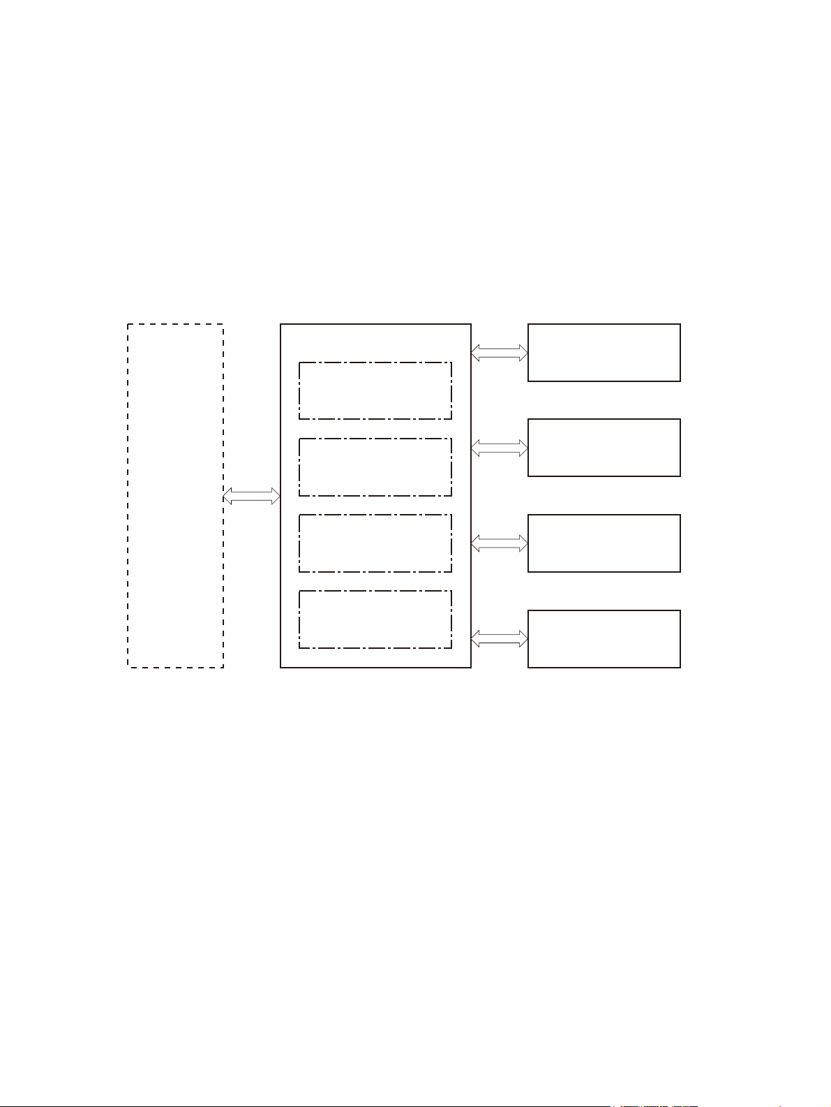
Engine control system
The engine-control system coordinates all the other systems, according to commands from the formatter.
The engine-control system contains the following components:
DC controller PCA
●
Low-voltage power supply unit
●
High-voltage power supply PCA
●
Fuser control
●
Figure 1-2 Engine control system
Formatter
Engine control system
DC controller
Low-voltage power supply
High-voltage power supply
Fuser control
Laser scanner system
Image-formation system
Pickup, feed and delivery
system
Accessory
4 Chapter 1 Theory of operation ENWW
Page 28

DC controller PCA
The DC controller PCA controls the product operation sequence.
Figure 1-3 DC controller PCA
AC input
Low-voltage
power supply
LED
Motor
Fuser
Transfer roller
Cartridge
Control panel
USB PCA
HIP
Formatter
High-voltage
power supply
Connector PCA
DC controller
Fan
Solenoid
Clutch
Photointerrupter
Sensor
Switch
Duplex unit
(Accessory)
Input source accessory
Laser scanner
ENWW
The following table lists the product electrical components.
Component type Component
abbreviation
Switch SW1 Left door interlock switch
SW2 Cartridge door interlock switch
SW3 Cartridge door open detection switch
SW4 Upper cassette media width switch
SW5 Lower cassette media width switch
SW6 Upper cassette media end switch
SW7 Lower cassette media end switch
—Power switch
Component name
Engine control system
5
Page 29

Component type Component
abbreviation
Solenoid SL1 Tray 1 (MP tray) pickup solenoid
Clutch CL1 Upper cassette pickup clutch
CL2 Lower cassette pickup clutch
Fan FM1 Rear fan
FM2 Front fan
FM3 Fuser fan
Photointerrupter SR1 Cartridge presence sensor
SR2 MP tray media out sensor
SR3 Output sensor
SR4 Output bin media full sensor
SR5 Lower cassette media out sensor
SR6 Loop sensor
SR7 Upper cassette media out sensor
SR8 Right door sensor
Component name
Sensor — Environment sensor
Motor M1 Drum motor
Motor control
The product has five motors for the paper-feed and image-formation.
SR9 TOP sensor
SR10 Upper cassette lift-up sensor
SR11 Lower cassette lift-up sensor
SR12 Fuser output sensor
M2 Scanner motor
M3 Fuser motor
M4 Upper cassette lifter motor
M5 Lower cassette lifter motor
6 Chapter 1 Theory of operation ENWW
Page 30
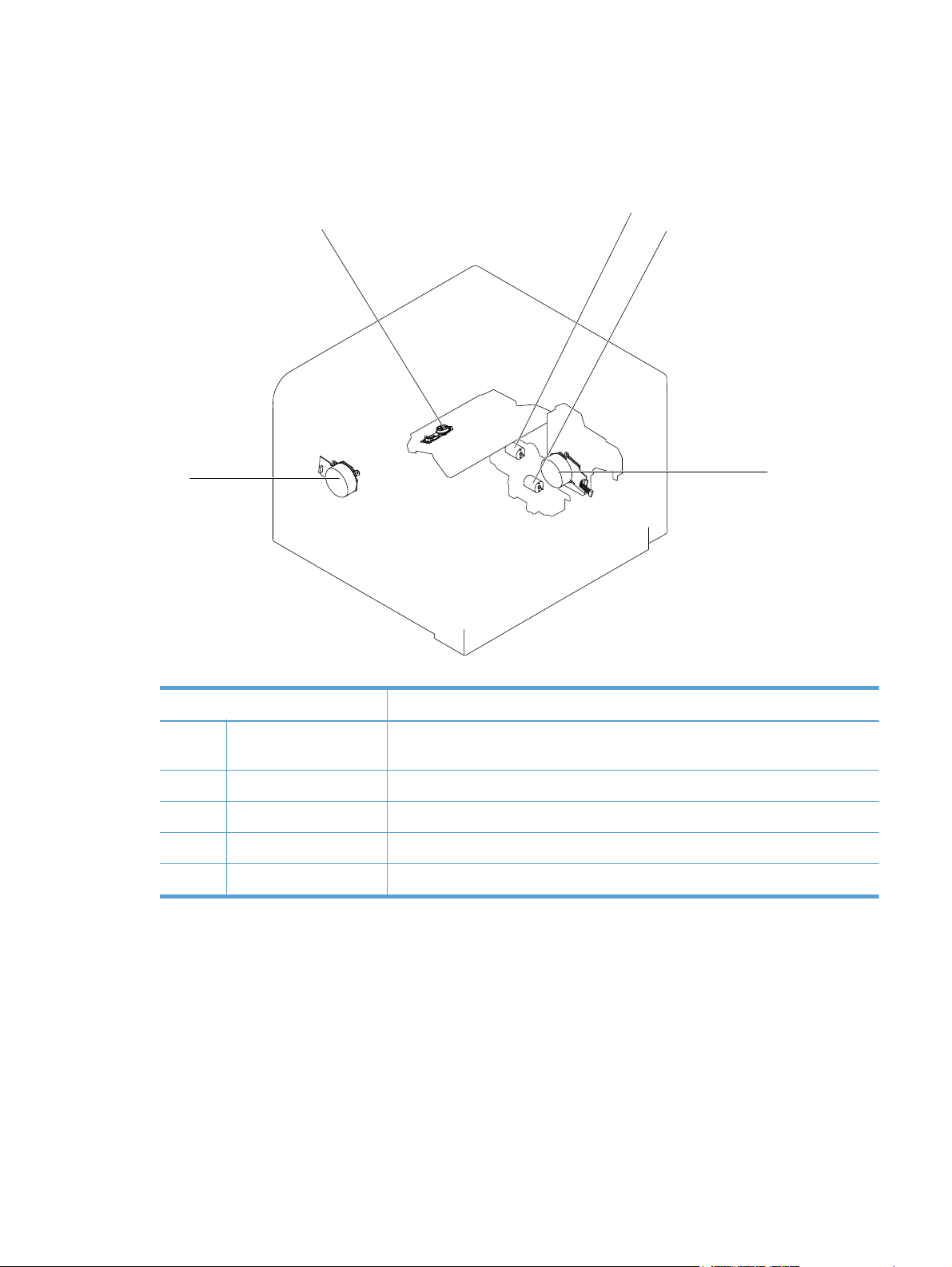
Motor locations
The following figure shows the product motor locations.
Figure 1-4 Motor locations
M2
M4
M5
M3
Table 1-2 Motor locations
Motor Components driven by motor
M1 Drum motor Photosensitive drum, transfer roller, registration roller, MP tray pickup roller, cassette
pickup roller, and feed roller
M2 Scanner motor Laser scanner mirror
M3 Fuser motor Pressure roller, fuser output roller, intermediate output roller and paper delivery roller
M4 Upper cassette lifter motor Lifter for the upper cassette
M5 Lower cassette lifter motor Lifter for the lower cassette
M1
Failure detection
The DC controller monitors the following motors to determine a motor failure:
Drum motor
●
Scanner motor
●
Fuser motor
●
ENWW
Engine control system
7
Page 31

The DC controller determines if the motor has failed and notifies the formatter when the motor
encounters the following conditions:
●
●
The DC controller notifies the formatter of a BD (beam detect) failure when it detects a rotational failure
of the scanner motor.
The DC controller monitors the related part condition of the following motors to determine a motor
failure:
●
●
Fan control
The product has three fans for preventing the temperature from rising in the product and cooling down
the delivered paper.
Startup failure — The motor does not reach a specified rotational count within a specified time
from when the motor starts.
Rotational failure — The rotational speed of the motor is not in the specified range for a specified
time after the motor reaches a specified speed.
Upper cassette lifter motor
Lower cassette lifter motor
8 Chapter 1 Theory of operation ENWW
Page 32
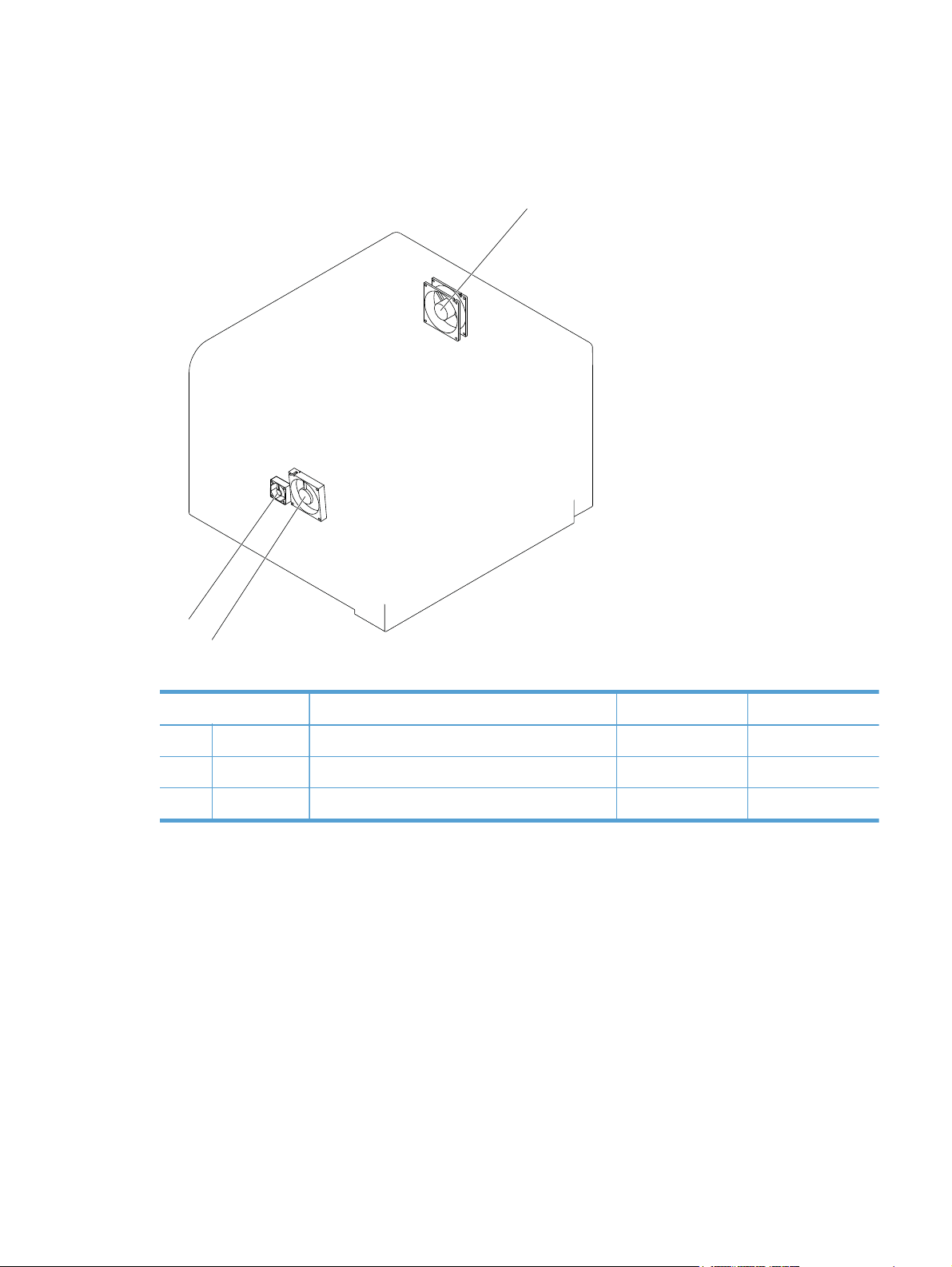
Fan locations
The following figure shows the product fan locations.
Figure 1-5 Fan locations
FM1
FM3
FM2
Table 1-3 Fan locations
Fan Cooling area Type Speed
FM1 Rear fan Product inside and low-voltage power supply area Exhaust Full/Mid/Low
FM2 Front fan Product inside Intake Full
FM3 Fuser fan Fuser area Intake Full
Failure detection
The DC controller determines if the fan has failed and notifies the formatter when the fan stops rotating
for a specified time during start-up.
ENWW
Engine control system
9
Page 33
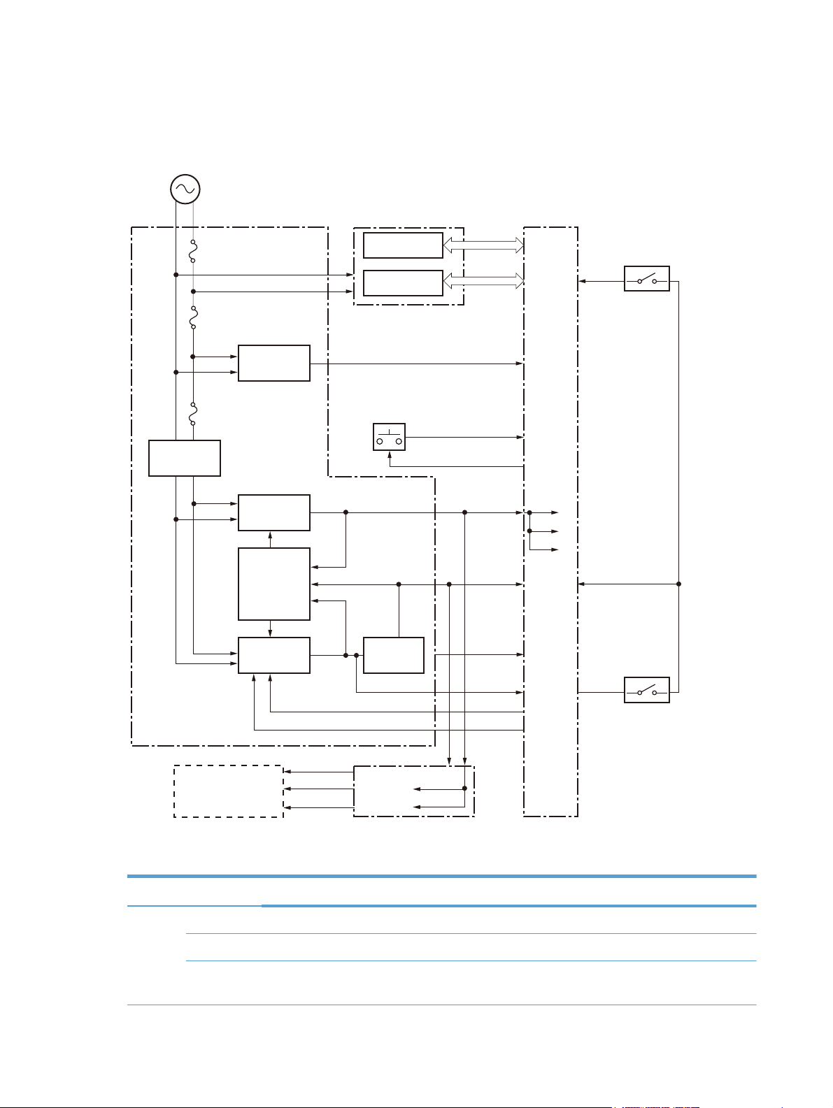
Low-voltage power-supply PCA
The low-voltage power supply converts AC power into the DC voltage that product components use.
Figure 1-6 Low-voltage power-supply PCA
AC input
Rectifying
circuit
Low-voltage power supply
Power fuse
FU1
Power fuse
FU2
Zerocross
detection
circuit
Power fuse
FU3
+3.3V
generation
circuit
Protection
circuit
High-voltage power supply
High-voltage
circuit
Fuser circuit
Power switch
/ZEROX
+3.3VA
+3.3VA
+5V
DC controller
+3.3VA
+3.3VC
+3.3VD
+24VD
+24VC
Interlock
switch
SW2
+5V
generation
circuit
Connector PCA
+3.3VA
+3.3VB
/PSTYP100
+24VB
RMT_24V
RMT_PFC
+24VB
+24VC
Interlock
switch
SW1
Formatter
+24V
generation
circuit
+3.3VA
+3.3VB
+5V
The following table shows the specifications for the DC power supply.
Table 1-4 Low voltage power supply DC power specifications
DC voltage Behavior
+24V +24VB Off during Sleep mode (sleep level1, active off and inactive off)
+24VC Off during Sleep mode (sleep level1, active off and inactive off) Interrupted when the left door open
+24VD Off during Sleep mode (sleep level1, active off and inactive off) Interrupted when the left door or
the cartridge door open
10 Chapter 1 Theory of operation ENWW
Page 34

Table 1-4 Low voltage power supply DC power specifications (continued)
DC voltage Behavior
+5V +5V Off during Sleep mode (sleep level1, active off and inactive off)
+3.3V +3.3VA Constantly supplied
+3.3VB Off during Sleep mode (inactive off)
+3.3VC Off during Sleep mode (active off and inactive off)
+3.3VD Off during Sleep mode (sleep level1, active off and inactive off)
Over-current/over-voltage/overload protection
The over-current/overvoltage protection automatically stops the DC voltage to the product components
whenever an excessive current or abnormal voltage is detected. The overload protection automatically
stops the DC voltage to the product components whenever the temperature of the low-voltage power
supply PCA rises to specified degrees.
The low-voltage power supply has a protective circuit against over-current, over-voltage and overload to
prevent failures in the power supply circuit. If DC voltage is not being supplied from the low-voltage
power supply, the protective function might be running. In this case, turn the power off and unplug the
power cord. Do not turn the product switch on until the root cause is found and corrected.
The DC controller determines a low-voltage power supply failure and notifies the formatter when the
protective function runs.
In addition, the low-voltage power supply has three fuses to protect against over-current. If over-current
flows into the AC line, the fuse blows to stop AC power.
Safety interruption
For user and service technician's safety, the product interrupts the power supply of +24V by turning off
the interlock switch. The DC power to the following components is interrupted:
High-voltage power supply
●
Fuser motor
●
The remote switch control circuit turns on or off the product so that the AC power flows even the power
switch is turned off. Be sure to unplug the power cord before disassembling the product.
Power supply voltage detection
The power supply voltage detection controls the fuser properly according to the voltage. The DC
controller detects whether the low-voltage power supply voltage is 100V or 220V according to the
POWER SUPPLY VOLTAGE signal (/PSTYP100).
ENWW
Engine control system
11
Page 35

Sleep mode
The Sleep mode reduces the power consumption of the product. There are three types of sleep mode:
●
●
●
Sleep level 1
The DC controller stops the power supply of +24V according to the +24V CONTROL signal
(RMT_24V) and POWER FACTOR CORRECTION ACTIVATE signal (RMT_PFC) after a specified
period of time from when a sleep command signal is sent from the formatter. The DC controller
supplies +24V and the product exits sleep level 1 when a recover signal is sent from the formatter.
Active off
The DC controller stops the power supplies except for +3.3VA and +3.3VB to the formatter when
an active off command signal is sent from the formatter during sleep level 1 or STBY period. The
DC controller supplies all power supplies and the product exits active off when a recover signal is
sent from the formatter or the power switch is depressed for shorter than three seconds.
Inactive off
The DC controller stops the power supplies except for +3.3VA to the formatter when an inactive
off command signal is sent from the formatter during sleep level 1 or STBY period. The product
enters inactive off when the power switch is depressed for longer than three seconds. The DC
controller supplies all power supplies and the product exits inactive off when a recover signal is
sent from the formatter or the power switch is depressed for shorter than three seconds.
Power supply illumination control
The DC controller changes the light of the LED (power supply illumination) for the power switch
according to the power supply condition as follows:
Lighting-up: STBY period or sleep level 1
●
Blinking: Active off
●
Lighting-out: Inactive off
●
12 Chapter 1 Theory of operation ENWW
Page 36

High-voltage power-supply PCA
The high-voltage power supply applies positive or negative voltage biases to the following components:
Primary charging roller
●
Developing roller
●
Transfer roller
●
Static charge eliminator
●
Fuser film
●
Figure 1-7 High-voltage power-supply PCA
Fuser
Fuser film
DC controller
High-voltage power supply
Primary
charging bias
circuit
Developing
bias circuit
Static charge eliminator
Static charge
eliminatior
bias circuit
Transfer bias
circuit
Pressure roller
Cartridge
To primary charge roller
To developing roller
Photosensitive drum
Transfer roller
The DC controller controls the high-voltage power supply to generate the following biases.
Primary charging bias
●
ENWW
The primary charging bias is used to charge the surface of the photosensitive drum evenly to
prepare for image formation. The primary charging bias circuit generates the bias.
Developing bias
●
The developing bias is used to adhere toner to an electrostatic latent image formed on the
photosensitive drum. The developing bias circuit generates the bias.
Transfer bias
●
The transfer bias is used to transfer the toner from the photosensitive drum onto the paper. The
transfer bias circuit generates the bias. The transfer bias circuit also generates the reverse bias to
clean the transfer roller.
Engine control system
13
Page 37

Static charge eliminator bias
●
The static charge eliminator bias is used to improve the paper-feed performance and imagequality. The static charge eliminator bias circuit generates the bias.
Fusing bias
●
The fusing bias is used to improve the image-quality. The primary charging bias circuit generates
the bias.
14 Chapter 1 Theory of operation ENWW
Page 38

Fuser control
The fuser heater control circuit and the fuser heater safety circuit control the fuser temperature according
to commands from the DC controller. The product uses an on-demand fusing method.
Figure 1-8 Fuser components
TH1
TP1
H1/H2
TH4
Fuser film
TH3
TH2
Fuser heater
control circuit
Pressure roller
FUSER TEMPERATURE signal
FUSER HEATER CONTROL signal
Fuser heater
safety circuit
High-voltage power supply
ENWW
DC controller
The following table shows the function of each fuser component.
Component Function
H1 Fuser main heater Heats center area of the fuser film
H2 Fuser sub heater Heats both ends of the fuser film
TP1 Thermoswitch Prevents an abnormal temperature rise of the fuser heater (contact type)
TH1 Main thermistor Detects the temperature at center of the fuser heater (contact type)
Engine control system
15
Page 39

Component Function
TH2 Sub thermistor 1 Detects the temperature at ends of the fuser heater (contact type)
TH3 Sub thermistor 2
TH4 Sub thermistor 3
Figure 1-9 Fuser control system
AC input
RL1001
RL1002
Fuser heater
control circuit
Fuser heater safety circuit
Low-voltage power supply
Zerocross detection
circuit
High-voltage power supply
Relay drive circuit
Current
detection
circuit
Fuser control circuit
DC controller
/ZEROX
RLD
FSRD1
FSRD2
FSRCUR
MFSRTH
S1FSRTH
S2FSRTH
S3FSRTH
Fuser
Fuser film assembly
TH2
TH1
TH3
TP1
H1/H2
Pressure roller
TH4
16 Chapter 1 Theory of operation ENWW
Page 40

Fuser temperature control
The fuser temperature control maintains the temperature of the fuser heater at its targeted temperature.
The DC controller monitors the FUSER TEMPERATURE signals (MFSRTH, S1FSRTH, S2FSRTH and
S3FSRTH) and sends the FUSER HEATER CONTROL signals (FSRD1 and FSRD2). The fuser heater
control circuit controls the fuser heater depending on the signals so that the fuser heater remains at the
targeted temperature.
Fuser heater protective function
The fuser heater protective function detects an abnormal temperature rise of the fuser and interrupts
power supply to the fuser heater. The following protective components prevent an abnormal
temperature rise of the fuser heater:
DC controller
●
The DC controller monitors the detected temperature of the thermistor. The DC controller releases
the relay (RL1001) to interrupt power supply to the fuser heater when it detects an abnormal
temperature.
Fuser heater safety circuit
●
The fuser heater safety circuit monitors the detected temperature of the thermistor. The fuser heater
safety circuit releases the relays (RL1001 and RL1002) or deactivates the fuser heater control
circuit to interrupt power supply to the fuser heater when it detects an abnormal temperature.
Thermoswitch
●
The contact of the thermoswitch is broken to interrupt power supply to the fuser heater when the
temperature of the fuser heater is abnormally high.
Current detection circuit
●
The current detection circuit monitors the current value flowing in the fuser heater control circuit,
and it releases the relay to interrupt power supply to the fuser heater when it detects an abnormal
current flow.
The DC controller deactivates the FUSER HEATER CONTROL signal and releases the relays
(RL1001 and RL1002) to interrupt power supply to the fuser heater when it detects out of a
specified current value of the CURRENT DETECTION signal (FSRCUR).
ENWW
Engine control system
17
Page 41

Fuser failure detection
The DC controller determines if the fuser functions properly. The DC controller determines a fuser
failure, interrupts power supply to the fuser heater and notifies the formatter of a failure state when it
encounters the following conditions:
Abnormally high temperature 1
●
The main thermistor detects 240°C (464°F) or higher for a specified period.
Abnormally high temperature 2
●
The sub thermistor 1 detects 230°C (446°F) or higher for a specified period during WAIT period.
The sub thermistor 1 detects 230°C (446°F) or higher for a specified period before INTR starts.
The sub thermistor 1 detects 300°C (572°F) or higher for a specified period.
Abnormally high temperature 3
●
Either one of the sub thermistor 2 or sub thermistor 3 detects 230°C (446°F) or higher for a
specified period during WAIT period.
Either one of the sub thermistor 2 or sub thermistor 3 detects 230°C (446°F) or higher for a
specified period before INTR starts.
Either one of the sub thermistor 2 or sub thermistor 3 detects 300°C (572°F) or higher for a
specified period.
Abnormally low temperature 1
●
The main thermistor detects 60°C (140°F) or lower for a specified period during WAIT period.
The main thermistor detects 70°C (158°F) or lower for a specified period during heater
temperature control of INTR period.
The main thermistor detects the targeted temperature minus 40°C (104°F) or lower for a specified
period during heater temperature control or pressure roller cleaning of PRINT period.
The main thermistor detects 80°C (176°F) or lower for a specified period during heater
temperature control or pressure roller cleaning of PRINT period.
Abnormally low temperature 2
●
The sub thermistor 1 detects 60°C (140°F) or lower for a specified period during WAIT period.
Abnormally low temperature 3
●
Either one of the sub thermistor 2 or sub thermistor 3 detects 60°C (140°F) or lower for a specified
period during WAIT period.
Abnormal temperature rise
●
The main thermistor detects the targeted temperature minus 10°C (50°F) or lower for a specified
period during heater temperature control of INTR period.
Drive circuit failure
●
18 Chapter 1 Theory of operation ENWW
Page 42

The frequency of the ZEROCROSS signal is not detected in a specified value within a specified
period after power-on.
The frequency of the ZEROCROSS signal is not detected in a specified value for a specified
period after power-on and once the signal is detected.
Heater failure
●
A specified current value or lower is detected during the heater drive period of the WAIT period
or when more than a specified electrical power is input.
Pressure roller cleaning
The pressure roller cleaning clears toner on the pressure roller surface by adhering to the paper
according to a command from the formatter. This is executed only when the paper size is A4-R (rotated)
or Letter-R (rotated). The operational sequence of the pressure roller cleaning is as follows:
1. The DC controller picks up the paper from the designated input source when a cleaning command
is sent from the formatter.
2. When the trailing edge of paper passes through the transfer roller, the fuser motor repeats to
rotate-and-stop at regular intervals and the fuser heater turns on-and-off at the same time.
3. The toner on the pressure roller fuses onto the paper and the roller clears.
4. The paper with fused toner is delivered out of the product.
ENWW
Engine control system
19
Page 43

Laser scanner system
The DC controller controls the laser scanner system according to commands from the formatter. The DC
controller controls the internal components in the laser scanner system to form latent electrostatic image
on the photosensitive drum according to the VIDEO signals. The following are the main components of
the laser scanner system:
Laser assembly
●
Scanner motor assembly
●
BD (beam detect) sensor
●
Scanner mirror
●
Figure 1-10 Laser scanner system
DC controller
Laser assembly
Scanner mirror
Scanner motor assembly
BD sensor
Photosensitive drum
20 Chapter 1 Theory of operation ENWW
Page 44

Laser scanner failure detection
The DC controller determines a laser scanner failure and notifies the formatter of the error state when
any of the following conditions occurs:
BD failure
●
A specified BD interval is not detected within a specified period during the scanner motor drive.
Scanner motor start-up failure
●
The scanner motor does not reach a specified rotation within a specified period from when the
laser scanner starts driving.
Laser failure
●
A specified laser intensity is not detected.
Laser scanner safety function
The laser scanner has a mechanical shutter. For user and service technician safety, the laser shutter
interrupts optical path of the laser scanner when the cartridge door is open.
ENWW
Laser scanner system
21
Page 45

Image-formation system
The DC controller controls the image-formation system according to commands from the formatter. The
DC controller controls the internal components of the image-formation system to form the toner image
on the photosensitive drum surface. The toner image is transferred to the paper and fused.
The following are the main components of the image-formation system:
Cartridge
●
Transfer roller
●
Fuser
●
Laser scanner
●
High-voltage power supply
●
Figure 1-11 Image-formation system
Laser scanner
Fuser
High-voltage power supply
DC controller
Transfer roller
Cartridge
The DC controller rotates the drum motor to drive the following components:
Photosensitive drum
●
Developing roller (follows the photosensitive drum)
●
Primary charging roller (follows the photosensitive drum)
●
Transfer roller
●
The DC controller rotates the fuser motor to drive the following components:
Pressure roller
●
Fuser film (follows the pressure roller)
●
22 Chapter 1 Theory of operation ENWW
Page 46

Figure 1-12 Image-formation components
Photosensitive drum
Fuser motor
Fuser film
Pressure roller
Image-formation process
The image-formation process consists of seven steps divided into five functional blocks:
Cartridge
Drum motor
Primary charging roller
Developing roller
Transfer roller
Fuser
DC controller
Latent-image-formation system
●
Step 1: Primary charging
◦
Step 2: Laser-beam exposure
◦
Developing system
●
Step 3: Developing
◦
Transfer system
●
Step 4: Transfer
◦
Step 5: Separation
◦
ENWW
Image-formation system
23
Page 47
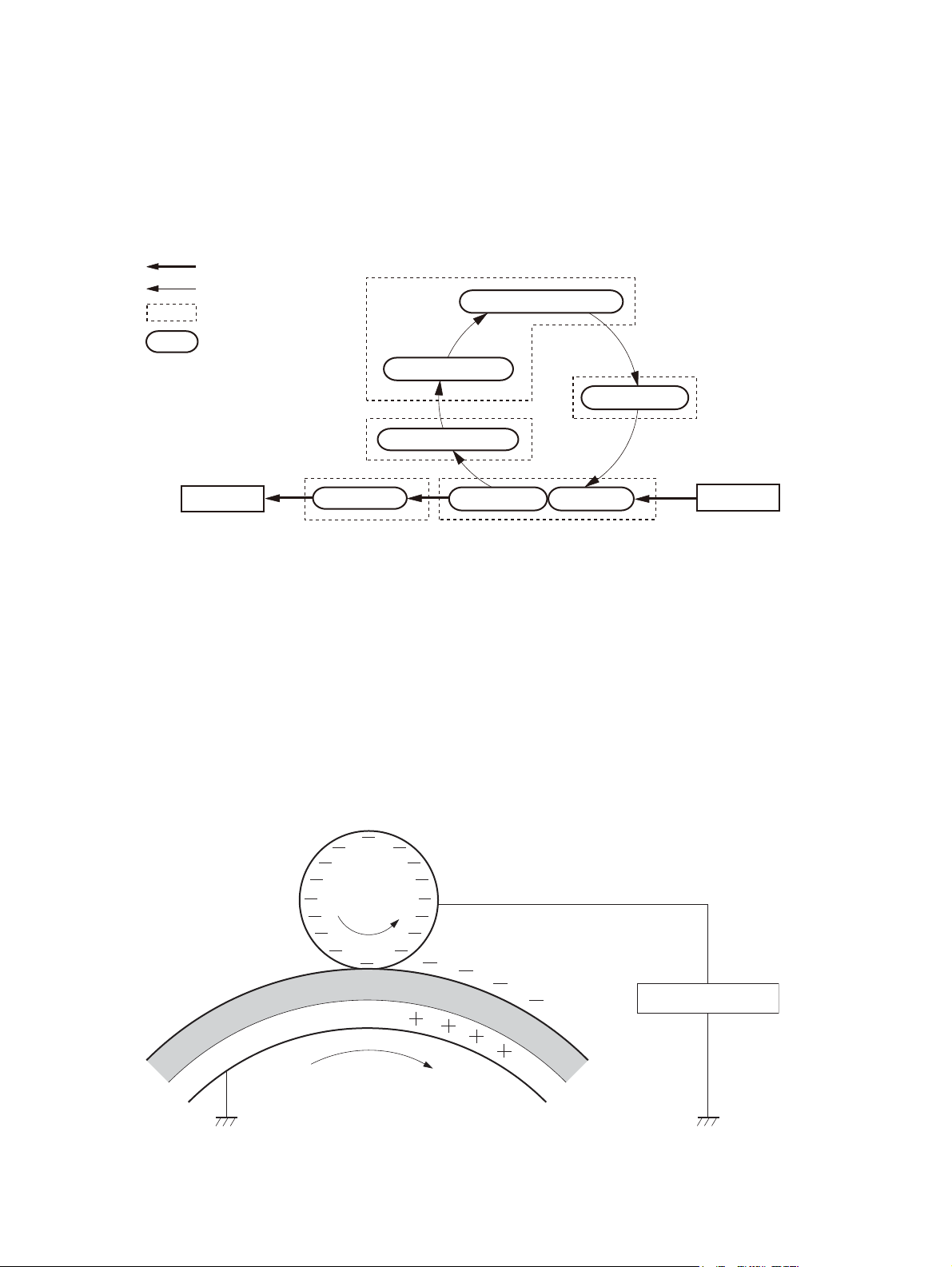
Fuser system
●
Step 6: Fusing
◦
Drum cleaning
●
Step 7: Drum cleaning
◦
Figure 1-13 Image-formation process
: Paper path
: Direction of the drum rotation
: Functional block
: Step
1. Primary charging
7. Drum cleaning
Latent image formation
2. Laser-beam exposure
3. Developing
Developing
Delivery
6. Fusing
Fusing
Latent-image formation block
During the two steps that comprise this block, an invisible latent image is formed on the photosensitive
drum.
Step 1: primary charging
To prepare for latent image formation, the surface of the photosensitive drum is charged with a uniform
negative potential. The primary charging roller charges the photosensitive drum directly. The primary
charging bias is applied to the primary charging roller to keep a negative potential on the drum
surface.
Figure 1-14 Primary charging
Primary charging roller
5. Separation
4. Transfer
Transfer
Pickup
Primary charging bias
Photosensitive drum
24 Chapter 1 Theory of operation ENWW
Page 48
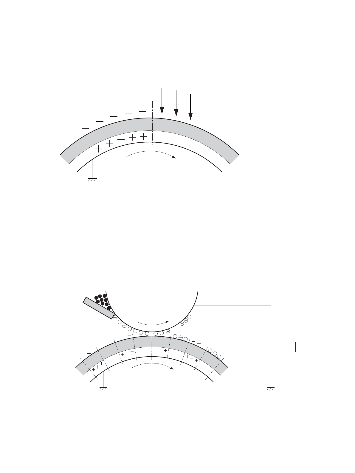
Step 2: laser-beam exposure
The laser-beam strikes the surface of the photosensitive drum to neutralize the negative charge. An
electrostatic latent image forms where the negative charge was neutralized.
Figure 1-15 Laser-beam exposure
Development block
Toner adheres to the electrostatic latent image on the photosensitive drum, which becomes visible.
Laser beam
Photosensitive drum
Step 3: developing
Toner acquires a negative charge from the friction that occurs when the developing roller rotates
against the developer blade. The developing bias is applied to the developing roller to make difference
in the electric potential of the drum. The negatively charged toner is attracted to the latent image on the
photosensitive drum because the drum surface has a higher potential. The latent image becomes visible
on the drum.
Figure 1-16 Developing
Developer blade
Developing roller
Developing bias
Photosensitive drum
ENWW
Image-formation system
25
Page 49

Transfer block
During the two steps that comprise this block, a toner image on the photosensitive drum transfers to the
paper.
Step 4: image transfer
The toner on the photosensitive drum is transferred to the paper. The transfer bias is applied to the
transfer roller to charge the paper positive. The negatively charged toner on the drum surface transfers
onto the paper.
Figure 1-17 Image transfer
Transfer roller
Photosensitive
drum
Paper
Transfer bias
Step 5: separation from the drum
The elasticity of the paper and the curvature of the photosensitive drum cause the paper to separate
from the photosensitive drum. The static charge eliminator bias is applied to the static charge
eliminator. The static charge eliminator reduces back side static discharge of the paper after the
transfer process for stable paper-feed and print-quality.
Figure 1-18 Separation from the drum
Photosensitive
Static charge eliminator
Static charge
eliminator bias
drum
Paper
Transfer roller
26 Chapter 1 Theory of operation ENWW
Page 50

Fuser block
Until the fusing stage is complete, the image is not permanently affixed to the paper. The toner can be
easily smudged until the heat and pressure of the fusing process fix the image to the sheet.
Step 6: fusing
The toner melts by the heat and pressure as the paper passes through the rollers. The toner image is
permanently fused to the paper. The fusing bias is applied to the fuser film to improve print-quality.
Figure 1-19 Fusing
Fuser heater
Fuser film
Toner
Paper
Fusing bias
Pressure roller
Drum-cleaning block
The residual toner is removed from the photosensitive drum surface
Step 7: drum cleaning
The cleaning blade scrapes the residual toner off the surface of the photosensitive drum and toner is
deposited in the toner collection box.
Figure 1-20 Drum cleaning
Cleaning blade
Toner collection box
Toner cartridge
The cartridge is filled with toner and consists of the following components:
Photosensitive drum
●
Photosensitive
drum
ENWW
Developing roller
●
Image-formation system
27
Page 51

Primary charging roller
●
Memory tag
●
Figure 1-21 Toner cartridge components
Drum motor
DC controller
High-voltage power supply
Cartridge
Memory Tag
Primary
charging
roller
Developing roller
Photosensitive drum
The cartridge serves a role in the following functions:
Memory tag
●
The memory tag is a non-volatile memory in the cartridge and the DC controller controls it. The
memory tag stores information about usage for the cartridge and the DC controller reads and
writes the data in the memory tag. The DC controller determines an memory tag error and notifies
the formatter when it fails to either read from or write to the memory tag.
Cartridge-presence detection
●
The DC controller detects whether the cartridge is installed in the product by monitoring the
cartridge presence sensor. The DC controller notifies the formatter when it determines a cartridge
absence.
Toner-level detection
●
28 Chapter 1 Theory of operation ENWW
Page 52
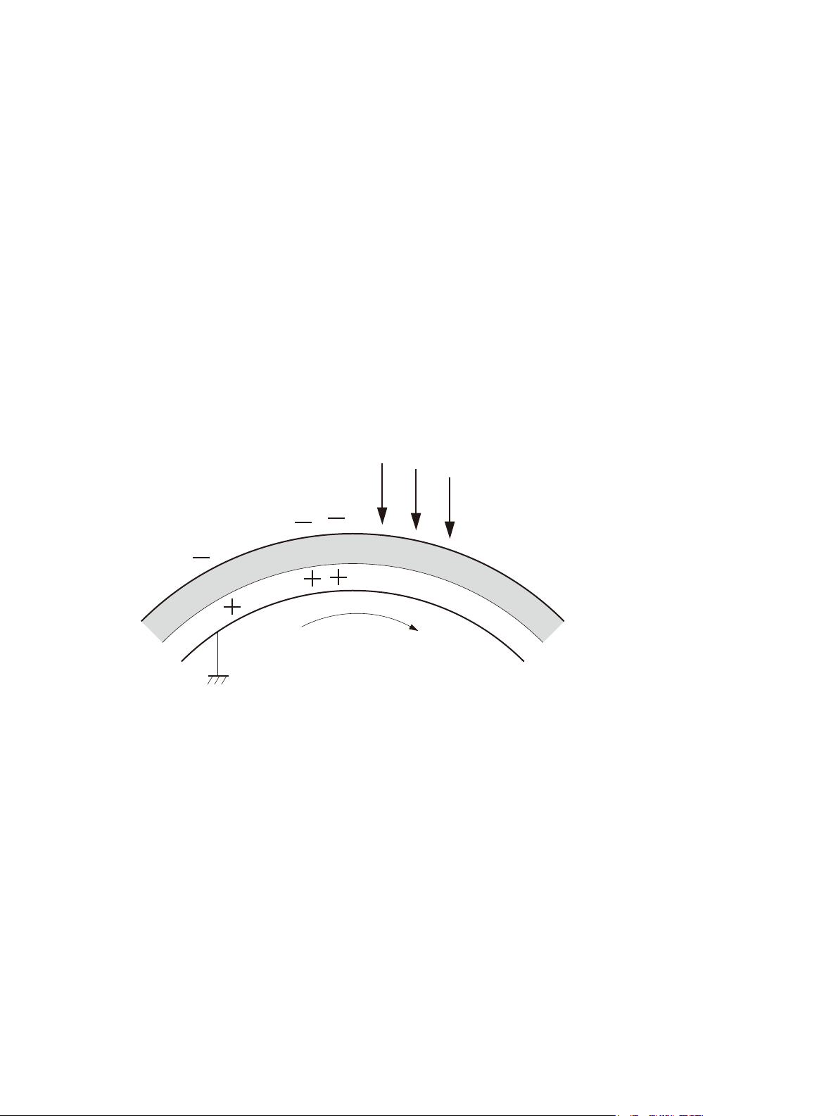
The DC controller detects the remaining toner level in a cartridge according to the TONER LEVEL
signal. The DC controller determines a cartridge low warning or cartridge end of life when the
toner level drops below a specified level and notifies the formatter.
Cartridge-life detection
●
The DC controller detects the cartridge life of components that wear out. The DC controller
determines a cartridge end of life and notifies the formatter.
Other image-formation functions
Drum discharge
The drum discharge is a feature to remove residual charge on the photosensitive drum surface for
preventing the uneven image density. The laser-beam strikes the surface of the photosensitive drum to
remove the residual charge.
The drum discharge is performed during LSTR period.
Figure 1-22 Drum discharge
Laser beam
Transfer roller cleaning
The transfer roller cleaning is a feature to remove residual toner on the transfer roller surface for
preventing the back side toner stain of the paper.
The residual toner reverse transfers to the photosensitive drum by applying the reverse transfer bias to
the transfer roller. The residual toner is deposited in the toner collection box.
ENWW
Photosensitive drum
Image-formation system
29
Page 53

The transfer roller cleaning is performed during WAIT period, INTR period, LSTR period and after
forming the image for the front side of page when duplex printing.
Figure 1-23 Transfer roller cleaning
Cleaning blade
Photosensitive
Toner collection box
Reverse transfer bias
Environment change control
The environment change control calibrates each high-voltage bias to obtain an appropriate image
according to the environment changes.
drum
Transfer roller
The DC controller determines the environment, where the product is installed, based on the surrounding
temperature and humidity data from the environment sensor. It adjusts the high-voltage biases to
accommodate environmental changes.
The DC controller determines an environment sensor abnormality and notifies the formatter when it
detects out of specified range data from the environment sensor.
30 Chapter 1 Theory of operation ENWW
Page 54

Pickup, feed, and delivery system
The DC controller controls the pickup, feed and delivery system according to commands from the
formatter. The DC controller controls each block to pickup, feed and deliver the paper. The pickup,
feed and delivery system consists of following three functional blocks:
Pickup-and-feed block
●
Fuse-and-delivery block
●
Duplex block
●
Figure 1-24 Pickup, feed, and delivery system
Fuse-and-delivery
block
Pickup-and-feed block
DC controller
Simplex paper path
Duplex paper path
The figure below shows the sensors and switches for the pickup, feed and delivery system.
ENWW
Pickup, feed, and delivery system
31
Page 55

Figure 1-25 Pickup, feed, and delivery system sensors and switches
SR4
SW1
SR3
SW3
SW2
SW8
SR12
SR2
PS1
SR6
SR9
SR8
SR7
SW6
SW4
SW7 SW5
SR10
SR11
SR5
Table 1-5 Pickup, feed, and delivery system sensors and switches
Component Signal
SW1 Left door interlock switch LEFT DOOR OPEN DETECTION signal
SW2 Cartridge door interlock switch CARTRIDGE DOOR OPEN DETECTION signal
SW3 Cartridge door open detection switch CARTRIDGE DOOR OPEN DETECTION signal
SW4 Upper cassette media width switch UPPER CASSETTE MEDIA WIDTH signal
SW5 Lower cassette media width switch LOWER CASSETTE MEDIA WIDTH signal
SW6 Upper cassette media end switch UPPER CASSETTE MEDIA END signal
SW7 Lower cassette media end switch LOWER CASSETTE MEDIA END signal
SR2 MP tray media out sensor MP TRAY MEDIA OUT signal
SR3 Output sensor OUTPUT signal
SR4 Output bin media full sensor OUTPUT BIN MEDIA FULL signal
SR5 Lower cassette media out sensor LOWER CASSETTE MEDIA OUT signal
SR6 Loop sensor LOOP LEVEL signal
SR7 Upper cassette media out sensor UPPER CASSETTE MEDIA OUT signal
SR8 Right door sensor RIGHT DOOR OPEN DETECTION signal
SR9 TOP sensor TOP signal
SR10 Upper cassette lift-up sensor UPPER CASSETTE LIFT-UP signal
SR11 Lower cassette lift-up sensor LOWER CASSETTE LIFT-UP signal
SR12 Fuser output sensor FUSER OUTPUT signal
The figure below shows the solenoid and motors for the pickup, feed and delivery system.
32 Chapter 1 Theory of operation ENWW
Page 56
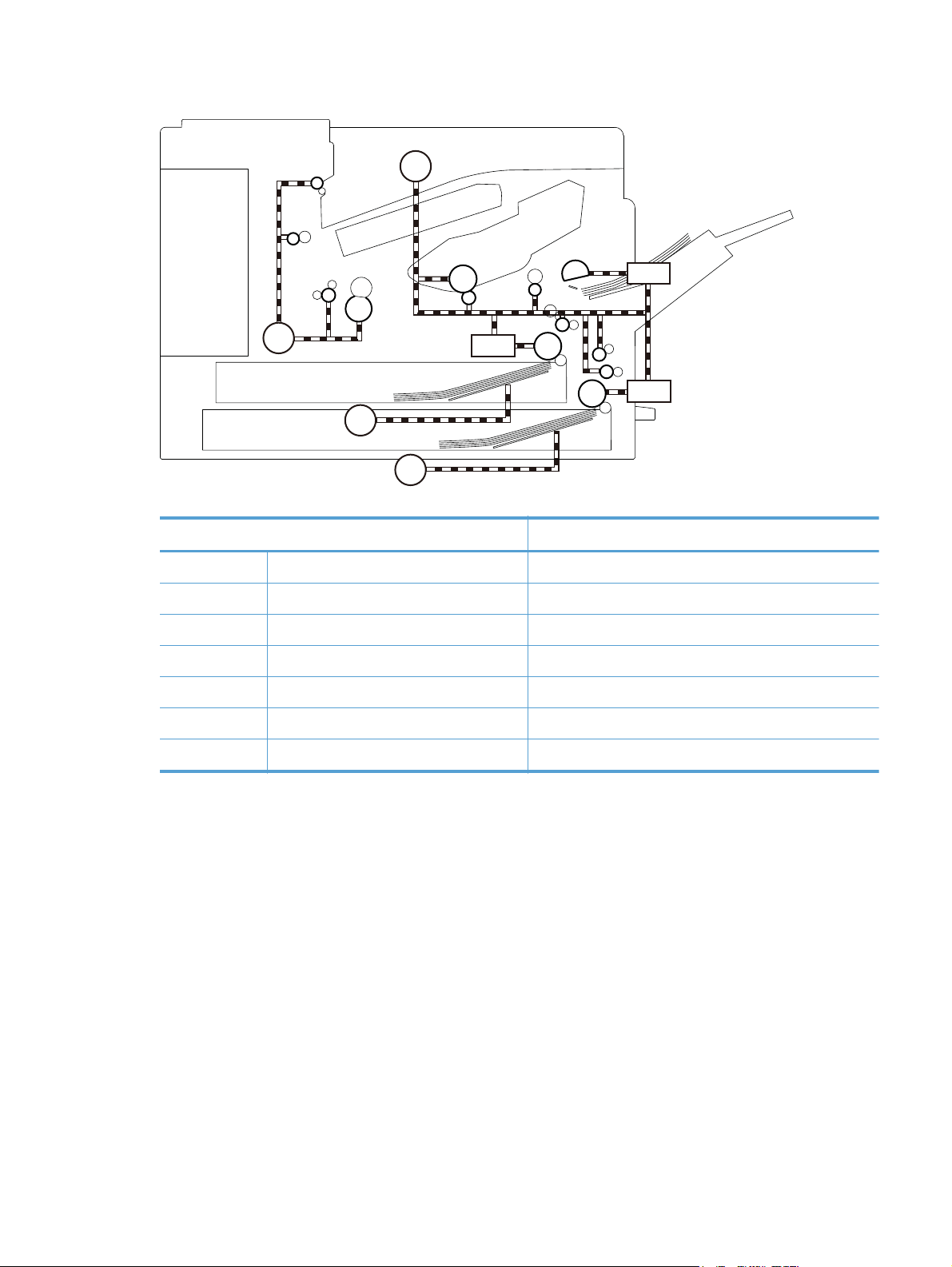
Figure 1-26 Pickup, feed, and delivery-system solenoid and motors
M1
SL1
M3
CL1
CL2
M4
M5
Table 1-6 Pickup, feed, and delivery system solenoid and motors
Component Signal
SL1 MP tray pickup solenoid MP TRAY PICKUP SOLENOID signal
CL1 Upper cassette pickup clutch UPPER CASSETTE PICKUP CLUTCH signal
CL2 Lower cassette pickup clutch LOWER CASSETTE PICKUP CLUTCH signal
M1 Drum motor DRUM MOTOR CONTROL signal
M3 Fuser motor FUSER MOTOR CONTROL signal
M4 Upper cassette lifter motor UPPER CASSETTE LIFTER MOTOR CONTROL signal
M5 Lower cassette lifter motor LOWER CASSETTE LIFTER MOTOR CONTROL signal
ENWW
Pickup, feed, and delivery system
33
Page 57

Pickup and feed block
The pickup-and-feed block picks one sheet of paper from the cassette or the MP tray and feeds it into
the fuser.
Figure 1-27 Pickup and feed block
34 Chapter 1 Theory of operation ENWW
Page 58

Cassette pickup
The product picks up one sheet of paper from the cassette. The following figure shows the cassette
pickup mechanism. Both trays have the same mechanism.
Figure 1-28 Cassette pickup mechanism
Cassette pickup clutch
Cassette pickup roller
DC controller
M1
Drum motor
CL
Feed roller
Cassette separation roller
The operational sequence of the cassette pickup is as follows:
1. The DC controller rotates the drum motor when it receives a print command from the formatter.
2. The feed roller rotates.
3. The cassette pickup solenoid is driven at a specified timing.
4. The cassette pickup roller rotates and picks up the top paper
5. The cassette separation roller removes any multiple-fed sheets.
6. One sheet of paper is fed into the product.
Cassette media-size detection and cassette-presence detection
The DC controller determines the size of the paper loaded in the cassette and also whether the cassette
is installed to the product by monitoring the cassette media width switch and the cassette media end
switch.
The cassette media width switch and the cassette media end switch contain three sub-switches each.
The DC controller detects the size of paper and the presence of cassette according to the combination
of the switches and notifies the formatter.
ENWW
Pickup, feed, and delivery system
35
Page 59

The cassette media-size detection and the cassette-presence detection are not performed during Sleep
mode. The following table lists the combination of the switches.
Table 1-7 Media switch combinations
Paper size Cassette media width switch Cassette media end switch
Top Center Bottom Top Center Bottom
Cassette
absence
A5-R OFF OFF OFF — ON ON
B5-R ON ON OFF — ON ON
Executive-R OFF ON OFF — ON ON
Letter-R OFF ON ON — ON ON
A4-R ON ON ON — ON ON
8.5 x 13 in OFF OFF OFF — ON OFF
Legal OFF OFF OFF — OFF ON
B4 ON ON OFF — OFF ON
LedgerOFFONON— OFFON
A3 ON ON ON — OFF ON
OFF OFF OFF — OFF OFF
Cassette lift operation
There are two types of cassette lift operation: cassette lift-up and cassette lift-down. The paper stack
surface is lifted up to the pickup position. The lifting plate is lifted down when the pickup operation is
not performed. The lift-up and lift-down operations are described in the following. Both upper and lower
cassettes perform the same operation.
Lift-up operation
The DC controller rotates the cassette lifter motor until the cassette lift-up sensor detects the lifter rack.
Accordingly the lifter moves up and the lifting plate moves up to the pickup position. The lift-up
operation is performed when the product is turned on or when the cassette is installed.
The DC controller determines a cassette lifter motor failure and notifies the formatter when the cassette
lift-up sensor does not detect the lifter rack within a specified period from when the lift-up operation
starts.
Lift-down operation
The paper loaded in the cassette presses against the cassette pickup roller when the lifting plate is in
the pickup position. If this condition is kept for a long time, the paper deformed and a pickup failure
may occur. Therefore, the lifting plate is moved down to release the paper from the pickup roller when
a print operation is not performed.
36 Chapter 1 Theory of operation ENWW
Page 60
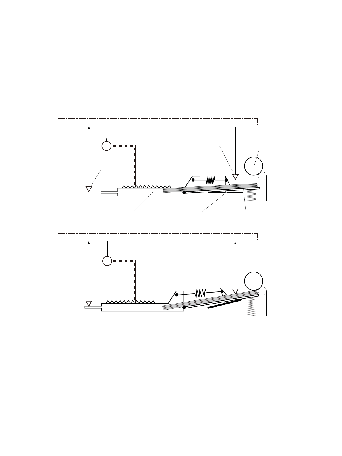
The DC controller reverses the cassette lifter motor until the cassette lift-up sensor stops sensing the lifter
rack when a print job is not sent for a specified period.
The DC controller determines a cassette lifter motor failure and notifies the formatter when the cassette
lift-up sensor keeps sensing the lifter rack for a specified period from when the lift-down operation
starts.
The following figure shows the mechanism of the cassette lift operation for the upper cassette. Both
upper and lower cassettes have the same mechanism.
Figure 1-29 Cassette lift operation
Before lift-up
DC controller
After lift-up
Cassette lifter motor
M1
Cassette lift-up sensor
SR10
Lifter rack
M1
DC controller
Cassette media out sensor
Lifter
Cassette pickup roller
SR7
Lifting plate
Cassette media-presence detection
The DC controller detects whether the paper is loaded in the cassette by monitoring the cassette media
out sensor. The cassette media-presence detection is not performed during Sleep mode. The DC
controller determines a media-absence and notifies the formatter when the cassette media out sensor
does not detect the paper.
Cassette multiple-feed prevention
The product uses a cassette separation roller to prevent the multiple sheets of paper from entering to the
product. The cassette separation roller follows the rotation of the cassette pickup roller. When multiple
ENWW
Pickup, feed, and delivery system
37
Page 61
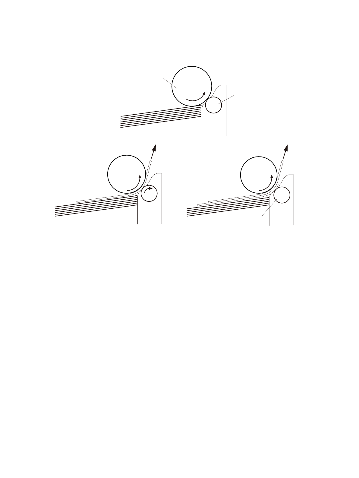
sheets are picked up, the cassette separation roller does not rotate and only one sheet is fed into the
product.
Figure 1-30 Cassette multiple feed prevention
Cassette pickup roller
Cassette separation roller
Paper
The cassette separation roller does not rotate.
<Multiple-feed><Normal-feed>
38 Chapter 1 Theory of operation ENWW
Page 62

MP tray pickup
The product picks up one sheet of paper from the MP tray.
Figure 1-31 MP tray pickup
DC controller
Drum motor
M1
MP tray pickup roller
MP tray separation pad
MP tray pickup solenoid
SL1
MP tray
media out sensor
SR2
Lifting plate
Paper
The operational sequence of the MP tray pickup is as follows:
1. The DC controller rotates the drum motor when it receives a print command from the formatter.
2. The MP tray pickup solenoid is driven at a specified timing.
3. The MP tray pickup roller rotates.
4. The lifting plate moves up.
5. The MP tray pickup roller picks up the top paper.
6. The MP tray separation pad removes any multiple-fed sheets.
7. One sheet of paper is fed into the product.
MP tray media-presence detection
The DC controller detects whether the paper is loaded in the MP tray by monitoring the MP tray media
out sensor. The MP tray media-presence detection is not performed during Sleep mode. The DC
controller determines a media-absence and notifies the formatter when the MP tray media out sensor
does not detect the paper.
ENWW
Pickup, feed, and delivery system
39
Page 63

MP tray multiple-feed prevention
The product uses a MP tray separation pad to prevent the multiple sheets of paper from entering to the
product. When multiple sheets are picked up, multiple sheets stop due to the friction against the MP
tray separation pad.
Figure 1-32 MP tray multiple-feed prevention
MP tray pickup roller
MP tray separation pad
Paper
Feed-speed control
The feed-speed control adjusts the paper feeding speed to improve the print-quality depending on the
paper types. The DC controller feeds the paper at a specified speed according to the print mode
designated by the formatter.
The following table shows the print mode and corresponding feed-speed.
Print mode Feed-speed
Auto —
Normal
Heavy media 1 1/1
Heavy media 2 1/2
Heavy media 3 —
Light media 1 1/1
Light media 2 1/1
Light media 3 —
1/1, 1/2
<Multiple-feed><Normal-feed>
1
Glossy media 1 —
Glossy media 2 —
40 Chapter 1 Theory of operation ENWW
Page 64

Print mode Feed-speed
Glossy media 3 —
Glossy film —
Photo media 1 —
Photo media 2 —
Photo media 3 —
Envelope 1 1/1
Envelope 2 1/2
Envelope 3 —
OHT 1/2
Label —
Designated media 1 —
Designated media 2 —
Designated media 3 —
1
The product will run at half speed in normal mode when the specific Print Quality, Optimize mode for reducing toner
explosions is selected.
ENWW
Pickup, feed, and delivery system
41
Page 65

Skew-feed prevention
The product uses a registration shutter to correct the skew feed without decreasing the feeding speed.
Figure 1-33 Skew-feed prevention
Registration shutter
Paper
Feed roller
Registration shutter
Feed roller
Paper
The operational sequence of the skew-feed prevention is as follows:
1. The leading edge of paper strikes the registration shutter as the paper is fed.
2. The leading edge of paper is aligned with the shutter.
3. As the feed roller keeps pushing the paper, the paper warps.
4. The stiffness of paper pushes up the registration shutter.
5. The paper passes through the registration shutter and straightens.
42 Chapter 1 Theory of operation ENWW
Page 66

Media-length detection
The DC controller detects the length of paper to prevent the toner stain on the transfer roller and also to
minimize jam occurrences in the duplexer. The DC controller measures the length of paper by
monitoring the time from when the leading edge of paper reaches at the TOP sensor until when the
trailing edge passes through and determines the paper size.
The DC controller determines a media-size mismatch and notifies the formatter when the detected paper
size is under the following conditions:
The detected paper size is different from the size designated by the formatter.
●
The detected paper size is different from the size detected by the cassette media size switch.
●
ENWW
Pickup, feed, and delivery system
43
Page 67

Fuse and delivery block
The fuse and delivery block fuses the toner image onto the paper and delivers the printed page to the
face-down output bin.
Figure 1-34 Fuse and delivery block
Output bin
Loop control
The product controls the loop of paper to prevent the defects of print-quality and paper-feed.
If the fuser film/pressure roller rotates slower than the photosensitive drum/transfer roller, the
●
paper loop increases.
If the fuser film/pressure roller rotates faster than the photosensitive drum/transfer roller, the paper
●
loop decreases.
44 Chapter 1 Theory of operation ENWW
Page 68

The DC controller detects the loop amount by monitoring the loop sensor and controls the rotational
speed of the fuser motor.
Figure 1-35 Loop control
Fuser film/Pressure roller rotates slower than photosensitive drum/transfer roller.
DC controller
Fuser motor
Fuser film
Pressure roller
SR6
Loop sensor
Fuser film/Pressure roller rotates faster than photosensitive drum/transfer roller.
Drum motor
Paper
Loop sensor lever
M1M3
Photosensitive
drum
Transfer roller
ENWW
Pickup, feed, and delivery system
45
Page 69

Output bin media-full detection
The DC controller detects whether the output bin is full by monitoring the output bin media full sensor.
Figure 1-36 Output bin media-full detection
DC controller
Output bin media full sensor
SR4
Output bin media full
sensor lever
Output bin
Paper
The DC controller determines an output bin media full and notifies the formatter when the output bin
media full sensor detects the paper for a specified period during a print operation.
46 Chapter 1 Theory of operation ENWW
Page 70

Jam detection
The product uses the following sensors and switches to detect the presence of paper and to check
whether the paper is being fed correctly or has jammed:
Left door interlock switch (SW1)
●
Cartridge door interlock switch (SW2)
●
Cartridge door open detection switch (SW3))
●
TOP sensor (SR9)
●
Loop sensor (SR6)
●
Fuser output sensor (SR12)
●
Output sensor (SR3)
●
Output bin media full sensor (SR4)
●
Right door sensor (SR8)
●
Figure 1-37 Product engine jam detection sensors and switches
SR4
No pick jam 1
MP tray
●
The TOP sensor does not detect the leading edge of paper within a specified period (including
two retries) from when the MP tray pickup solenoid is turned on.
Standard cassette
●
SW1
SR3
SR12
SR6
SW3
SW2
SR9
ENWW
The TOP sensor does not detect the leading edge of paper within a specified period (including
two retries) from when the cassette pickup clutch is driven.
Duplexer
●
Pickup, feed, and delivery system
47
Page 71

The TOP sensor does not detect the leading edge of paper within a specified period from when
the paper passes through the duplex waiting position.
Input accessory
●
The TOP sensor does not detect the leading edge of paper within a specified period from when
the following sensor of the input accessory installed on the top detects the leading edge.
500-sheet paper feeder: PF cassette media feed sensor
◦
1x500-sheet paper deck: PD cassette 1 media feed sensor
◦
3x500-sheet paper deck: PD cassette 1 media feed sensor
◦
3,500-sheet paper deck: HCI cassette media feed sensor
◦
Feed stay jam 1
The TOP sensor does not detect the trailing edge of paper within a specified period from when it
detects the leading edge.
Fuser output delay jam 1
The fuser output sensor does not detect the leading edge of paper within a specified period from when
the TOP sensor detects the leading edge.
Fuser output stay jam 1
The fuser output sensor does not detect the trailing edge of paper within a specified period from when
the TOP sensor detects the trailing edge.
Output delay jam 1
The output sensor does not detect the leading edge of paper within a specified period from when the
TOP sensor detects the leading edge.
Output delay jam 2
The output bin media full sensor does not detect the leading edge of paper within a specified period
from when the TOP sensor detects the leading edge.
Output stay jam 1
The output sensor does not detect the trailing edge of paper within a specified period from when the
fuser TOP sensor detects the trailing edge.
48 Chapter 1 Theory of operation ENWW
Page 72

Residual paper jam 1
Either one of the following sensors detects a paper-presence when the product is turned on or when the
door is closed:
TOP sensor
●
Loop sensor
●
Fuser output sensor
●
Either one of the following sensors detects a paper-presence when the automatic delivery is complete:
TOP sensor
●
Loop sensor
●
Fuser output sensor
●
Output sensor
●
Fuser wrap jam 1
The fuser output sensor detects a paper-absence within a specified period from when it detects the
leading edge of paper.
Door open jam 1
Either one of the following switches or sensor detects a door open during a paper feed operation:
Left door interlock switch
●
Cartridge door interlock switch
●
Cartridge door open detection switch
●
Right door sensor
●
Multiple-feed jam 1
The sub thermistor 1 detects 300°C (572°F) or higher for a specified period from when the multiple fed
sheets passes through the TOP sensor.
Automatic delivery
The product automatically clears the paper if the output sensor detects the residual paper when the
product is turned on or when the door is closed.
ENWW
Pickup, feed, and delivery system
49
Page 73

500-sheet paper feeder (Tray 4)
The paper feeder is optionally installed at bottom of the product. It picks up the paper and feeds it to
the product. The paper feeder controller controls the operational sequence of the paper feeder.
Figure 1-38 500-sheet paper feeder paper path
PF cassette pickup roller
PF cassette feed roller
500-sheet paper feeder
Figure 1-39 500-sheet paper feeder signal flow
+24V
DC controller
PF controller
PF cassette separation roller
500-sheet paper feeder
Motor
Solenoid
Photointerrupter
Switch
50 Chapter 1 Theory of operation ENWW
Page 74

Table 1-8 500-sheet paper feeder electrical components
Component Abbreviation Component name
Motor M1 PF cassette pickup motor
M2 PF cassette lifter motor
Solenoid SL1 PF cassette pickup solenoid
Photointerrupter SR1 PF cassette media feed sensor
SR2 PF cassette media stack surface sensor
SR3 PF cassette media out sensor
Switch SW1 PF right door open detection switch
SW2 PF cassette media width switch
SW3 PF cassette media end switch
500-sheet paper feeder motor control
The paper feeder has two motors for the paper-feed and cassette lift-up.
Figure 1-40 500-sheet paper feeder motor locations
PF cassette lifter motor
Table 1-9 500-sheet paper feeder motors
Motor Components driven
M1 PF cassette pickup motor Pickup roller, separation roller and feed roller for the PF cassette
M2 PF cassette lifter motor Lifter for the PF cassette
500-sheet paper feeder failure detection
The paper feeder controller determines a cassette lifter motor failure according to the condition of the
related part. The paper feeder controller does not determine if the cassette pickup motor has failed;
therefore, a jam occurs when the motor fails.
PF cassette pickup motor
ENWW
500-sheet paper feeder (Tray 4)
51
Page 75

500-sheet paper feeder pickup and feed operation
The pickup-and-feed operation picks up one sheet of paper in the paper feeder cassette and feeds it to
the product.
Figure 1-41 500-sheet paper feeder pickup and feed components
SR2SR3
SW2
Table 1-10 500-sheet paper feeder pickup and feed components
Component Signal
M1 PF cassette pickup motor PF CASSETTE PICKUP MOTOR CONTROL signal
SW3
SL1
M1M2
SR1
SW1
M2 PF cassette lifter motor PF CASSETTE LIFTER MOTOR CONTROL signal
SL1 PF cassette pickup solenoid PF CASSETTE PICKUP SOLENOID signal
SR1 PF cassette media feed sensor PF CASSETTE MEDIA FEED signal
SR2 PF cassette media stack surface sensor PF CASSETTE MEDIA STACK SURFACE signal
SR3 PF cassette media out sensor PF CASSETTE MEDIA OUT signal
SW1 PF right door open detection switch PF RIGHT DOOR OPEN DETECTION signal
SW2 PF cassette media width switch PF CASSETTE MEDIA WIDTH signal
SW3 PF cassette media end switch PF CASSETTE MEDIA END signal
52 Chapter 1 Theory of operation ENWW
Page 76
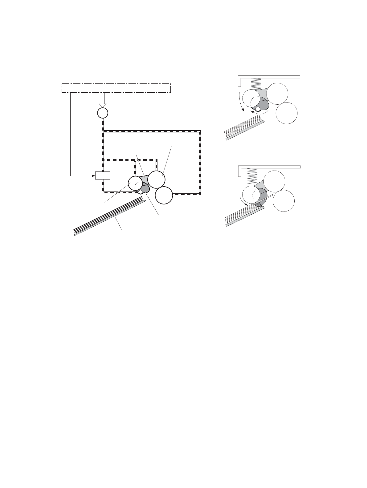
500-sheet paper feeder cassette pickup
The paper feeder picks up one sheet of paper from the cassette.
Figure 1-42 500-sheet paper feeder pickup and feed cassette pickup
PF controller
M1
PF cassette pickup motor
2
1
1. Cassette pickup cam rotates
2. Cassette pickup arm lowers
3
3. PF cassette pickup roller
picks up the paper
Cassette pickup arm
SL1
PF cassette
pickup solenoid
PF cassette pickup roller
PF cassette feed roller
PF cassette separation roller
Cassette pickup cam
Lifting plate
The operational sequence of the cassette pickup is as follows:
1. The paper feeder controller rotates the PF cassette pickup motor when it receives a print command
from the formatter.
2. The PF cassette pickup roller, PF cassette feed roller and PF cassette separation roller rotate.
3. The PF cassette pickup solenoid is driven at a specified timing.
4. The cassette pickup cam rotates.
5. The cassette pickup arm lowers and the PF cassette pickup roller picks up the top paper.
6. The PF cassette separation roller removes any multiple-fed sheets.
7. One sheet of paper is fed into the product.
500-sheet paper feeder cassette media-size detection and cassette-presence detection
The paper feeder controller determines the size of paper loaded in the cassette and also whether the
cassette is installed to the paper feeder by monitoring the PF cassette media width switch and the PF
cassette media end switch.
The PF cassette media width switch and the PF cassette media end switch contain three sub-switches
each. The paper feeder controller detects the size of paper and the presence of cassette according to
the combination of the sub-switches and notifies the formatter.
ENWW
500-sheet paper feeder (Tray 4)
53
Page 77

The cassette media-size detection and the cassette-presence detection are not performed during Sleep
mode.
Table 1-11 500-sheet paper feeder media switch combinations
Paper size Cassette media width switch Cassette media end switch
Top Center Bottom Top Center Bottom
Cassette
absence
A5-R ON ON OFF ON ON ON
B5-R OFF ON OFF ON ON ON
Executive-R OFF ON ON ON ON ON
Letter-R OFF OFF ON ON ON ON
A4-R OFF OFF OFF ON ON ON
8.5 x 13 in ON ON OFF OFF ON ON
Legal ON ON OFF OFF OFF ON
B4 OFF ON OFF OFF OFF ON
Ledger OFF OFF ON OFF OFF ON
A3 OFF OFF OFF OFF OFF ON
OFF OFF OFF OFF OFF OFF
500-sheet paper feeder lift-up operation
The paper feeder performs the lift-up operation to keep the surface of paper at the pickup position
whenever the following occurs:
The product is turned on
●
The cassette is installed
●
The paper stack surface lowers by pickup operation
●
Figure 1-43 500-sheet paper feeder lift-up operation
PF cassette media stack surface sensor
Lifting plate
SR2
Lifter
M2
PF cassette lifter motor
54 Chapter 1 Theory of operation ENWW
Page 78

The operational sequence of the lift-up is as follows:
1. The lifter motor rotates to raise the lifter.
2. The lifter motor stops when the PF cassette media stack surface sensor detects the paper surface.
3. The lifter motor rotates again when the PF cassette media stack surface sensor detects that the
stack surface lowers during a print operation.
The paper feeder controller determines a PF cassette lifter motor failure and notifies the formatter
through the DC controller when the PF cassette media stack surface sensor does not detect the paper
surface within a specified period from when the PF cassette lifter motor starts rotating.
500-sheet paper feeder cassette media-presence detection
The paper feeder controller detects whether the paper is loaded in the cassette by monitoring the PF
cassette media out sensor.
The cassette media-presence detection is not performed during Sleep mode.
The paper feeder controller determines a media-absence and notifies the formatter through the DC
controller when the PF cassette media out sensor does not detect the paper.
500-sheet paper feeder cassette multiple-feed prevention
The paper feeder uses a PF cassette separation roller to prevent the multiple sheets of paper from
entering to the product.
The PF cassette separation roller transmits its driving force so that the roller rotates in the same direction
with the PF cassette feed roller.
When one sheet of paper is picked up, driving force from the PF cassette feed roller transmits
●
through the single sheet of paper because the torque limiter functions and the PF cassette
separation roller follows the PF cassette feed roller. Therefore, single sheet is fed into the product.
When multiple sheets of paper are picked up, driving force from the PF cassette feed roller
●
becomes weak due to a low friction between the sheets. The PF cassette separation roller rotates
ENWW
500-sheet paper feeder (Tray 4)
55
Page 79
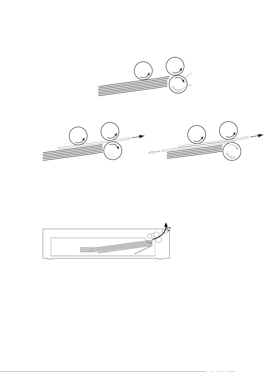
by its own driving force and the multiple-fed paper are pushed back to the cassette. Therefore,
single sheet is fed into the product.
Figure 1-44 500-sheet paper feeder multiple-feed prevention
PF cassette feed roller
PF cassette pickup roller
Driving force transmitted from
Paper
PF cassette separation roller
the PF cassette feed roller
Driving force transmitted from
the PF cassette pickup motor
<Normal-feed>
500-sheet paper feeder jam detection
The paper feeder uses the PF cassette media feed sensor (SR1) to detect the presence of paper and to
check whether paper is being fed correctly or has jammed.
Figure 1-45 500-sheet paper feeder cassette jam detection sensor
No pick jam 2
The PF cassette media feed sensor does not detect the leading edge of paper within a specified period
(including 2 retries) from when the PF cassette pickup solenoid is turned on.
Residual paper jam 1
<Multiple-feed>
PF cassette media feed sensor
SR1
The PF cassette media feed sensor detects a paper-presence when the automatic delivery is complete.
56 Chapter 1 Theory of operation ENWW
Page 80

Door open jam 1
A PF right door open is detected during a paper feed operation.
500-sheet paper feeder automatic delivery
The paper feeder automatically clears the paper if the PF cassette media feed sensor detects the
residual paper when the product is turned on or when the door is closed.
ENWW
500-sheet paper feeder (Tray 4)
57
Page 81
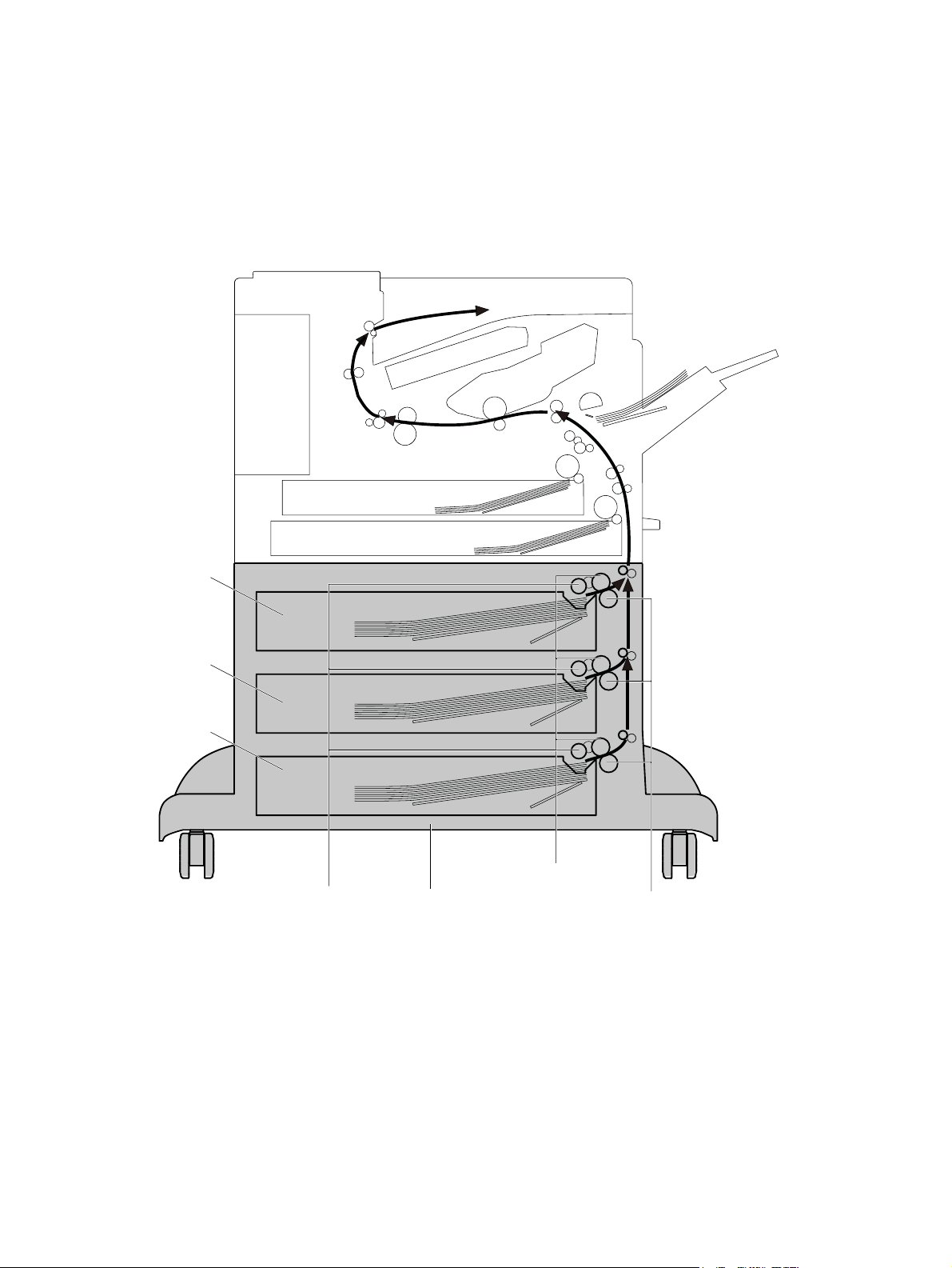
1x500 and 3x500 paper feeder and stand
The 1x500-sheet paper feeder is optionally installed at the bottom of the product or 500-sheet paper
feeder. The 3x500-sheet paper feeder is optionally installed at bottom of the product only. Each of the
paper feeders pick up the paper and feed it to the product. The paper feeder controller controls the
operational sequence of the paper feeder.
Figure 1-46 Paper deck paper path
Cassette 1
Cassette 2
Cassette 3
PD cassette feed roller
PD cassette pickup roller PD cassette separation roller
3x500-sheet paper deck
58 Chapter 1 Theory of operation ENWW
Page 82

Figure 1-47 Paper deck signal flow
Paper deck cassette 1
Motor
DC controller
+24V
(3x500 only)
PD controller 1
PD controller 2
Solenoid
Sensor
Switch
(3x500 only)
Paper deck cassette 2
Motor
Solenoid
Sensor
Paper deck cassette 3
Motor
(3x500 only)
PD controller 3
Solenoid
Sensor
Table 1-12 Paper deck electrical components
Component Abbreviation Component name
Motor M1 PD cassette 1 pickup motor
M2 PD cassette 1 lifter motor
M81
M82
M91
M92
PD cassette 2 pickup motor
PD cassette 2 lifter motor
PD cassette 3 pickup motor
PD cassette 3 lifter motor
1
1
1
1
ENWW
1x500 and 3x500 paper feeder and stand
59
Page 83

Table 1-12 Paper deck electrical components (continued)
Component Abbreviation Component name
Solenoid SL1 PD cassette 1 pickup solenoid
SL82
SL92
PD cassette 2 pickup solenoid
PD cassette 3 pickup solenoid
1
1
Photointerrupter SR1 PD cassette 1 media feed sensor
SR1 PD cassette 1 media feed sensor
SR3 PD cassette 1 media out sensor
SR81
SR82
SR83
SR91
SR92
SR93
Switch SW1
PD cassette 2 media feed sensor
PD cassette 2 media stack surface sensor
PD cassette 2 media out sensor
PD cassette 3 media feed sensor
PD cassette 3 media stack surface sensor
PD cassette 3 media out sensor
PD right door open detection switch
SW2 PD cassette 1 media width switch
SW3 PD cassette 1 media end switch
SW82
PD cassette 2 media width switch
1
1
1
1
1
1
1
1
1
Applies to the 3x500 paper deck only.
SW83
SW92
SW93
PD cassette 2 media end switch
PD cassette 3 media width switch
PD cassette 3 media end switch
1
1
1
60 Chapter 1 Theory of operation ENWW
Page 84

Paper deck motor control
The paper deck has two motors in each cassette for the paper-feed and cassette lift-up.
Figure 1-48 Paper deck motors
PD cassette lifter motor
PD cassette pickup motor
Table 1-13 Paper deck motors
Motor Components driven
M1 PD cassette 1 pickup motor Pickup roller, separation roller and feed roller for the PD cassette 1
M2 PD cassette 1 lifter motor Lifter for the PD cassette 1
M81 PD cassette 2 pickup motor Pickup roller, separation roller and feed roller for the PD cassette 2
M82 PD cassette 2 lifter motor Lifter for the PD cassette 2
M91 PD cassette 3 pickup motor Pickup roller, separation roller and feed roller for the PD cassette 3
M92 PD cassette 3 lifter motor Lifter for the PD cassette 3
Paper deck failure detection
The paper deck controller determines a PD cassette lifter motor failure according to the condition of the
related part.
The paper deck controller does not determine if the PD cassette pickup motor has failed; therefore, a
jam occurs when the motor fails.
Paper deck pickup-and-feed operation
ENWW
The pickup-and-feed operation picks up one sheet of paper in the paper deck cassette and feeds it to
the product.
1x500 and 3x500 paper feeder and stand
61
Page 85

NOTE: The following figure illustrates the mechanism for paper deck cassette 3, but each paper deck
cassette has the same mechanism.
Figure 1-49 Paper deck pickup and feed components
Cassette 1
Cassette 2
SW1
SR91
SR92SR93
Cassette 3
SW92
SW93
SL91
M91M92
Table 1-14 Paper deck pickup-and-feed operation components
Abbreviation Component Signal
M1 PD cassette 1 pickup motor PD CASSETTE 1 PICKUP MOTOR CONTROL signal
M2 PD cassette 1 lifter motor PD CASSETTE 1 LIFTER MOTOR CONTROL signal
SL1 PD cassette 1 pickup solenoid PD CASSETTE 1 PICKUP SOLENOID signal
SR1 PD cassette 1 media feed sensor PD CASSETTE 1 MEDIA FEED signal
SR2 PD cassette 1 media stack surface sensor PD CASSETTE 1 MEDIA STACK SURFACE signal
SR3 PD cassette 1 media out sensor PD CASSETTE 1 MEDIA OUT signal
SW1 PD right door open detection switch PD RIGHT DOOR OPEN DETECTION signal
SW2 PD cassette 1 media width switch PD CASSETTE 1 MEDIA WIDTH signal
SW3 PD cassette 1 media end switch PD CASSETTE 1 MEDIA END signal
M81 PD cassette 2 pickup motor PD CASSETTE 2 PICKUP MOTOR CONTROL signal
M82 PD cassette 2 lifter motor PD CASSETTE 2 LIFTER MOTOR CONTROL signal
SL81 PD cassette 2 pickup solenoid PD CASSETTE 2 PICKUP SOLENOID signal
SR81 PD cassette 2 media feed sensor PD CASSETTE 2 MEDIA FEED signal
SR82 PD cassette 2 media stack surface sensor PD CASSETTE 2 MEDIA STACK SURFACE signal
SR83 PD cassette 2 media out sensor PD CASSETTE 2 MEDIA OUT signal
SW82 PD cassette 2 media width switch PD CASSETTE 2 MEDIA WIDTH signal
62 Chapter 1 Theory of operation ENWW
Page 86

Table 1-14 Paper deck pickup-and-feed operation components (continued)
Abbreviation Component Signal
SW83 PD cassette 2 media end switch PD CASSETTE 2 MEDIA END signal
M91 PD cassette 3 pickup motor PD CASSETTE 3 PICKUP MOTOR CONTROL signal
M92 PD cassette 3 lifter motor PD CASSETTE 3 LIFTER MOTOR CONTROL signal
SL91 PD cassette 3 pickup solenoid PD CASSETTE 3 PICKUP SOLENOID signal
SR91 PD cassette 3 media feed sensor PD CASSETTE 3 MEDIA FEED signal
SR92 PD cassette 3 media stack surface sensor PD CASSETTE 3 MEDIA STACK SURFACE signal
SR93 PD cassette 3 media out sensor PD CASSETTE 3 MEDIA OUT signal
SW92 PD cassette 3 media width switch PD CASSETTE 3 MEDIA WIDTH signal
SW93 PD cassette 3 media end switch PD CASSETTE 3 MEDIA END signal
Paper deck cassette media-size detection and cassette-presence detection
The paper deck controller detects the size of paper loaded in the cassette and also whether the cassette
is installed to the paper deck by monitoring the PD cassette media width switch and the PD cassette
media end switch.
The PD cassette media width switch and the PD cassette media end switch contain three subswitches
each. The paper deck controller detects the size of paper and the presence of cassette according to the
combination of the sub-switches and notifies the formatter.
The cassette media-size detection and the cassette-presence detection are not performed during Sleep
mode.
Table 1-15 Paper deck media switch combinations
Paper size Cassette media width switch Cassette media end switch
Top Center Bottom Top Center Bottom
Cassette
absence
A5-R ON ON OFF ON ON ON
B5-R OFF ON OFF ON ON ON
Executive-R OFF ON ON ON ON ON
Letter-R OFF OFF ON ON ON ON
A4-R OFF OFF OFF ON ON ON
8.5 x 13 in ON ON OFF OFF ON ON
OFF OFF OFF OFF OFF OFF
ENWW
Legal ON ON OFF OFF OFF ON
B4 OFF ON OFF OFF OFF ON
1x500 and 3x500 paper feeder and stand
63
Page 87

Table 1-15 Paper deck media switch combinations (continued)
Paper size Cassette media width switch Cassette media end switch
Top Center Bottom Top Center Bottom
Ledger
A3 OFF OFF OFF OFF OFF ON
OFF OFF ON OFF OFF ON
Paper deck lift-up operation
The paper deck lifts up the tray to keep the surface of paper at the pickup position whenever the
following occurs:
The product is turned on
●
The cassette is installed
●
The paper stack surface lowers by pickup operation
●
NOTE: The following figure illustrates the mechanism for paper deck cassette 3, but each paper deck
cassette has the same mechanism.
Figure 1-50 Paper deck lift-up operation
Cassette 1
Cassette 2
PD cassette 3 media stack surface sensor
Cassette 3
Lifting plate
PD cassette 3 lifter motor
SR92
Lifter
M92
The operational sequence of the lift-up is as follows:
1. The PD cassette 3 lifter motor rotates to raise the lifter.
2. The PD cassette 3 lifter motor stops when the PD cassette 3 media stack surface sensor detects the
paper surface.
3. The PD cassette 3 lifter motor rotates again when the PD cassette 3 media stack surface sensor
detects that the stack surface lowers during a print operation.
64 Chapter 1 Theory of operation ENWW
Page 88

The paper deck controller 3 determines a PD cassette 3 lifter motor failure and notifies the formatter
through the DC controller when the PD cassette 3 media stack surface sensor does not detect the paper
surface within a specified period from when the PD cassette 3 lifter motor starts rotating.
Paper deck cassette media-presence detection
The paper deck controller detects whether the paper is loaded in the cassette by monitoring the PD
cassette media out sensor.
The cassette media-presence detection is not performed during Sleep mode.
The paper deck controller determines a media-absence and notifies the formatter through the DC
controller when the PD cassette media out sensor does not detect the paper.
Paper deck jam detection
The paper deck uses the following sensors to detect the presence of paper and to check whether paper
is being fed correctly or has jammed:
PD cassette 1 media feed sensor (SR1)
●
PD cassette 2 media feed sensor (SR81) (3x500-sheet paper deck only)
●
PD cassette 3 media feed sensor (SR91) (3x500-sheet paper deck only)
●
Figure 1-51 Paper deck jam detection sensors
No pick jam 2
The PD cassette 1 media feed sensor does not detect the leading edge of paper within a specified
period (including 2 retries) from when the PD cassette 1 pickup solenoid is turned on.
The PD cassette 1 media feed sensor does not detect the leading edge of paper within a specified
period from when the PD cassette 2 media feed sensor detects the leading edge. (3x500-sheet paper
deck only)
PD cassette 1 media feed sensor
SR1
PD cassette 2 media feed sensor
SR81
PD cassette 3 media feed sensor
SR91
ENWW
1x500 and 3x500 paper feeder and stand
65
Page 89

The PD cassette 1 media feed sensor does not detect the leading edge of paper within a specified
period from when the PD cassette 3 media feed sensor detects the leading edge. (3x500-sheet paper
deck only)
No pick jam 3 (3x500-sheet paper deck only)
The PD cassette 2 media feed sensor does not detect the leading edge of paper within a specified
period (including two retries) from when the PD cassette 2 pickup solenoid is turned on.
The PD cassette 3 media feed sensor does not detect the leading edge of paper within a specified
period (including two retries) from when the PD cassette 3 pickup solenoid is turned on.
Residual paper jam 1
The following sensor detects a paper-presence when the automatic delivery is complete.
PD cassette 1 media feed sensor
●
PD cassette 2 media feed sensor (3x500-sheet paper deck only)
●
PD cassette 3 media feed sensor (3x500-sheet paper deck only)
●
Door open jam 1
A PD right door open is detected during a paper feed operation.
Paper deck automatic delivery
The paper deck automatically clears the paper if either one of the following sensor detects the residual
paper when the product is turned on or when the door is closed:
PD cassette 1 media feed sensor
●
PD cassette 2 media feed sensor (3x500-sheet paper deck only)
●
PD cassette 3 media feed sensor (3x500-sheet paper deck only
●
66 Chapter 1 Theory of operation ENWW
Page 90

3,500-sheet high-capacity input (HCI) feeder
The 3,500-sheet paper deck is optionally installed at bottom of the product or the 500-sheet paper
feeder. It picks up the paper and feeds it to the product. The HCI controller controls the operational
sequence of the 3,500-sheet paper deck.
Figure 1-52 HCI paper path
3,500-sheet paper deck
Right cassette
Left cassette
HCI cassette pickup roller HCI cassette separation roller
HCI cassette feed roller
ENWW
3,500-sheet high-capacity input (HCI) feeder
67
Page 91

Figure 1-53 HCI signal flow
3,500-sheet paper deck
Motor
DC controller
+24V
HCI controller
Solenoid
Photointerrupter
Switch
Table 1-16 HCI electrical components
Component Abbreviation Component name
Motor M3301 HCI right cassette pickup motor
M3302 HCI right cassette lifter motor
M3303 HCI left cassette lifter motor
M3304 HCI left cassette pickup motor
Solenoid SL3301 HCI right cassette pickup solenoid
SL3302 HCI left cassette pickup solenoid
Photointerrupter PS3101 HCI right cassette media stack surface 2 sensor
PS3102 HCI right cassette media stack surface 1 sensor
PS3103 HCI right cassette media out sensor
PS3201 HCI left cassette media stack surface 2 sensor
PS3202 HCI left cassette media stack surface 1 sensor
PS3203 HCI left cassette media out sensor
PS3301 HCI media feed sensor
PS3302 HCI right cassette media feed sensor
PS3303 HCI right cassette media size sensor
PS3304 HCI left cassette media size sensor
PS3305 HCI left cassette media feed sensor
PS3306 HCI long edge feed guide open detection sensor
Switch SW3301 HCI right door open detection switch
SW3302 HCI right cassette open detection switch
SW3303 HCI left cassette open detection switch
68 Chapter 1 Theory of operation ENWW
Page 92
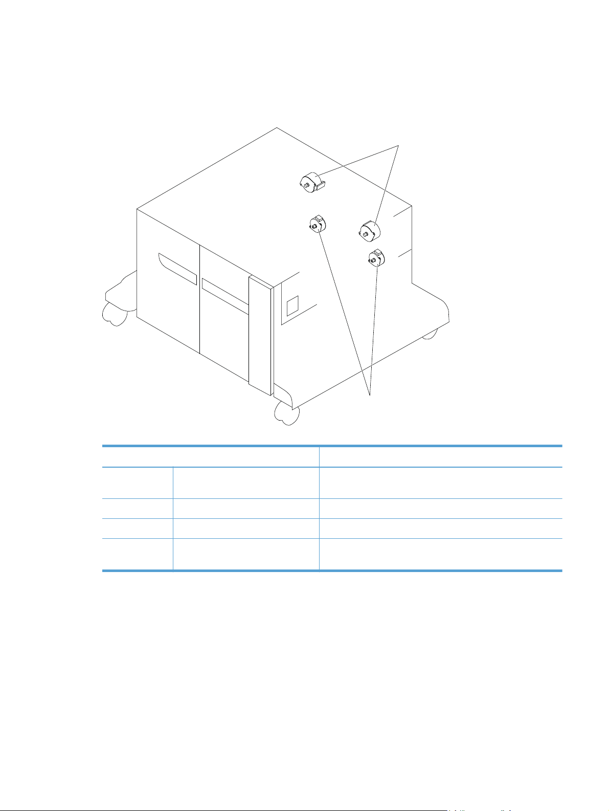
HCI motor control
The HCI has two motors in each cassette for the paper-feed and cassette lift-up.
Figure 1-54 HCI motors
HCI cassette pickup motor
Table 1-17 HCI motors
Motor Components driven
M3301 HCI right cassette pickup motor Pickup roller, separation roller and feed roller for the HCI right
M3302 HCI right cassette lifter motor Lifter for the HCI right cassette
M3303 HCI left cassette lifter motor Lifter for the HCI left cassette
M3304 HCI left cassette pickup motor Pickup roller, separation roller and feed roller for the HCI left
HCI failure detection
The HCI controller determines a lifter motor failure according to the condition of the related part.
The HCI controller does not determine if the HCI cassette pickup motor has failed; therefore, a jam
occurs when the motor fails.
HCI cassette lifter motor
cassette
cassette
ENWW
3,500-sheet high-capacity input (HCI) feeder
69
Page 93

HCI pickup-and-feed operation
The pickup-and-feed operation picks up one sheet of paper in the 3,500-sheet paper deck cassette and
feeds it to the product.
Figure 1-55 HCI pickup-and-feed operation
PS3201
SW3303
M3304
PS3203
PS3202
SL3302
PS3304
PS3101
M3302M3303
PS3103
PS3102
SW3302
PS3301
PS3306PS3305
SL3301
PS3303
M3301
PS3302
Table 1-18 HCI pickup-and-feed operation components
Abbreviation Component Signal
M3301 HCI right cassette pickup motor HCI RIGHT CASSETTE PICKUP MOTOR CONTROL
signal
M3302 HCI right cassette lifter motor HCI RIGHT CASSETTE LIFTER MOTOR CONTROL
signal
M3303 HCI left cassette lifter motor HCI LEFT CASSETTE LIFTER MOTOR CONTROL
signal
M3304 HCI left cassette pickup motor HCI LEFT CASSETTE PICKUP MOTOR CONTROL
signal
SL3301 HCI right cassette pickup solenoid HCI RIGHT CASSETTE PICKUP SOLENOID signal
SL3302 HCI left cassette pickup solenoid HCI LEFT CASSETTE PICKUP SOLENOID signal
PS3101 HCI right cassette media stack surface 2 sensor HCI RIGHT CASSETTE MEDIA STACK SURFACE 2
signal
PS3102 HCI right cassette media stack surface 1 sensor HCI RIGHT CASSETTE MEDIA STACK SURFACE 1
signal
70 Chapter 1 Theory of operation ENWW
Page 94

Table 1-18 HCI pickup-and-feed operation components (continued)
Abbreviation Component Signal
PS3103 HCI right cassette media out sensor HCI RIGHT CASSETTE MEDIA OUT signal
PS3201 HCI left cassette media stack surface 2 sensor HCI LEFT CASSETTE MEDIA STACK SURFACE 2
signal
PS3202 HCI left cassette media stack surface 1 sensor HCI LEFT CASSETTE MEDIA STACK SURFACE 1
signal
PS3203 HCI left cassette media out sensor HCI LEFT CASSETTE MEDIA OUT signal
PS3301 HCI media feed sensor HCI MEDIA FEED signal
PS3302 HCI right cassette media feed sensor HCI RIGHT CASSETTE MEDIA FEED signal
PS3303 HCI right cassette media size sensor HCI RIGHT CASSETTE MEDIA SIZE signal
PS3304 HCI left cassette media size sensor HCI LEFT CASSETTE MEDIA SIZE signal
PS3305 HCI left cassette media feed sensor HCI LEFT CASSETTE MEDIA FEED signal
PS3306 HCI long edge feed guide open detection sensor HCI LONG EDGE FEED GUIDE OPEN DETECTION
signal
SW3301 HCI right door open detection switch HCI RIGHT DOOR OPEN DETECTION signal
SW3302 HCI right cassette open detection switch HCI RIGHT CASSETTE OPEN DETECTION signal
SW3303 HCI left cassette open detection switch HCI LEFT CASSETTE OPEN DETECTION signal
HCI cassette media-size detection and cassette-presence detection
The HCI controller detects the size of paper loaded in the cassette by monitoring the HCI cassette
media size sensors. It determines whether A4-R or Letter-R is loaded and notifies the formatter through
the DC controller. It also detects whether the cassette is installed to the 3,500-sheet paper deck by
monitoring the HCI cassette open detection switches and notifies the formatter through the DC
controller.
The cassette media-size detection and the cassette-presence detection are not performed during Sleep
mode.
ENWW
3,500-sheet high-capacity input (HCI) feeder
71
Page 95

HCI lift-up operation
The HCI lifts up the tray to keep the surface of the paper at the pickup position whenever the following
occurs:
The product is turned on
●
The cassette is installed
●
The paper stack surface lowers by pickup operation
●
Figure 1-56 HCI lift-up operation
HCI left cassette
media stack surface 2
sensor
Wire
HCI left cassette media stack surface 1 sensor
PS3202
PS3201
Tray
Pulley
M3303
The figure above illustrates the mechanism for the left cassette, but each HCI cassette has the same
mechanism.
The operational sequence of the lift-up is as follows:
1. The HCI cassette lifter motor rotates the pulley to reel the wire. Accordingly the tray moves up.
2. The HCI cassette lifter motor stops when the HCI cassette media stack surface 2 sensor detects the
paper surface.
3. The HCI cassette lifter motor rotates again when the HCI cassette media stack surface 1 sensor
detects that the stack surface lowers during a print operation.
The HCI controller determines an HCI cassette lifter motor failure and notifies the formatter through the
DC controller when the HCI cassette media stack surface 2 sensor does not detect the paper surface
within a specified period from when the HCI cassette lifter motor starts rotating.
HCI cassette media-presence detection
The HCI controller detects whether the paper is loaded in the cassette by monitoring the HCI cassette
media out sensor.
The cassette media-presence detection is not performed during Sleep mode.
HCI left cassette lifter motor
72 Chapter 1 Theory of operation ENWW
Page 96

The HCI controller determines a media-absence and notifies the formatter through the DC controller
when the HCI cassette media out sensor does not detect the paper.
ENWW
3,500-sheet high-capacity input (HCI) feeder
73
Page 97

HCI jam detection
The HCI uses the following sensors to detect the presence of paper and to check whether paper is
being fed correctly or has jammed:
HCI media feed sensor (PS3301)
●
HCI right cassette media feed sensor (PS3302)
●
HCI left cassette media feed sensor (PS3305)
●
Figure 1-57 HCI jam detection sensors
HCI left cassette
media feed sensor
HCI media feed sensor
No pick jam 2
The HCI media feed sensor does not detect the leading edge of paper within a specified period from
when the HCI right cassette media feed sensor detects the leading edge.
The HCI media feed sensor does not detect the leading edge of paper within a specified period from
when the HCI left cassette media feed sensor detects the leading edge.
PS3305
PS3301
PS3302
HCI right cassette
media feed sensor
No pick jam 3
The HCI right cassette media feed sensor does not detect the leading edge of paper within a specified
period, including two times retry, from when the HCI right cassette pickup solenoid is turned on.
The HCI left cassette media feed sensor does not detect the leading edge of paper within a specified
period, including two times retry, from when the HCI left cassette pickup solenoid is turned on.
74 Chapter 1 Theory of operation ENWW
Page 98

Residual paper jam 1
Either one of the following sensors detects a paper-presence when the automatic delivery is complete:
HCI media feed sensor
●
HCI right cassette media feed sensor
●
HCI left cassette media feed sensor
●
Door open jam 1
An HCI right door open or an HCI long edge feed guide open is detected during a paper-feed
operation.
HCI automatic delivery
The HCI automatically clears the paper if either one of the following sensors detects the residual paper
when the product is turned on or when the door is closed:
HCI media feed sensor
●
HCI right cassette media feed sensor
●
HCI left cassette media feed sensor
●
ENWW
3,500-sheet high-capacity input (HCI) feeder
75
Page 99

Duplexer
The optional duplexer is installed in the left side of the product. The duplexer reverses the output roller
and intermediate output roller in the product engine, reverses and feeds the paper passed through the
fuser. Then it detects side misregistration to adjust the starting position of the scanning direction for the
second side of paper according to the command from the formatter and feeds it to the product engine.
Figure 1-58 Duplexer paper path
Output roller
Intermediate output roller
Side misregistration sensor
Re-pickup roller
Duplex unit
Figure 1-59 Duplexer signal flow
+24V
DC controller
Duplex controller
Duplex reverse roller
Simplex paper path
Duplex paper path
Duplex re-pickup roller
Duplex unit
Motor
Fan
Clutch
Photointerrupter
Side misregistration sensor
LED
Photoreceiver
sensor
NVRAM
76 Chapter 1 Theory of operation ENWW
Page 100

Table 1-19 Duplexer electrical components
Component Abbreviation Component name
Motor M1 Duplex feed motor
Fan FM1 Duplex fan
Clutch CL1 Duplex feed clutch
Photointerrupter SR1 Duplex reverse sensor
Duplexer motor control
The duplexer has one motor. The duplex feed motor reverses the output roller and the intermediate
output roller. Also it drives the duplex reverse roller and the duplex re-pickup roller to feed the paper
and to drive the side misregistration sensor and the re-pickup roller.
Figure 1-60 Duplexer motor
SR2 Duplex re-pickup sensor
Duplex feed motor
Table 1-20 Duplexer motor
Motor Components driven
M1 Duplex feed motor Duplex reverse roller, duplex re-pickup roller, re-pickup roller, output roller
Duplexer motor failure detection
The duplex controller does not determine if the duplex feed motor has failed; therefore, a jam occurs
when the motor fails.
ENWW
and intermediate output roller
Duplexer
77
 Loading...