

2-139
MOTION SENSING
AND CONTROL
General Purpose Motion
Control ICs
Technical Data
HCTL-1100 Series
Description
The HCTL-1100 series is a high
performance, general purpose
motion control IC, fabricated in
HP CMOS technology. It frees the
host processor for other tasks by
performing all the time-intensive
functions of digital motion
control. The programmability of
all control parameters provides
maximum flexibility and quick
Features
• Low Power CMOS
• PDIP and PLCC Versions
Available
• Enhanced Version of the
HCTL-1000
• DC, DC Brushless, and Step
Motor Control
• Position and Velocity
Control
• Programmable Digital Filter
and Commutator
• 8-Bit Parallel, and PWM
Motor Command Ports
• TTL Compatible
• SYNC Pin for Coordinating
Multiple HCTL-1100 ICs
• 100 kHz to 2 MHz Operation
• Encoder Input Port
design of control systems with a
minimum number of components.
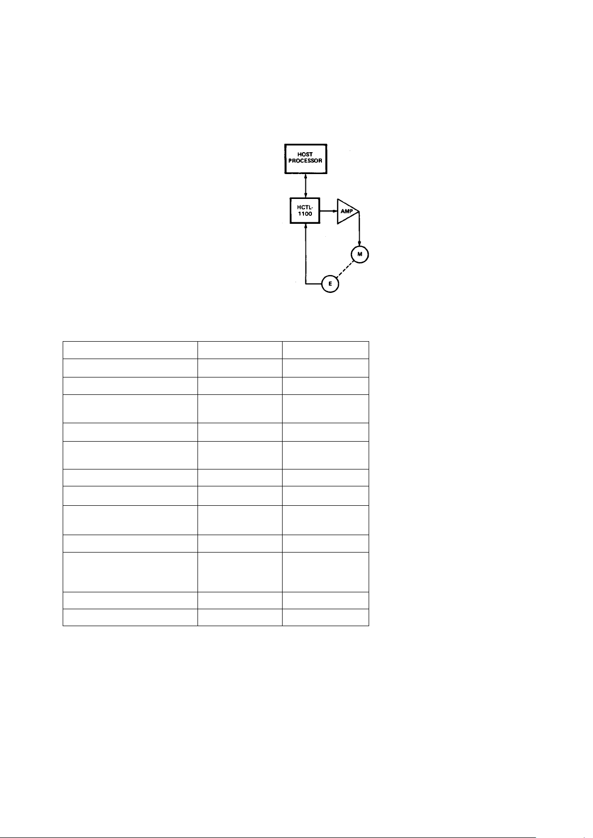
In addition to the HCTL-1100, the
complete control system consists
of a host processor to specify
commands, an amplifier, and a
motor with an incremental
encoder (such as the HP HEDS5XXX, -6XXX, -9XXX series). No
analog compensation or velocity
feedback is necessary.
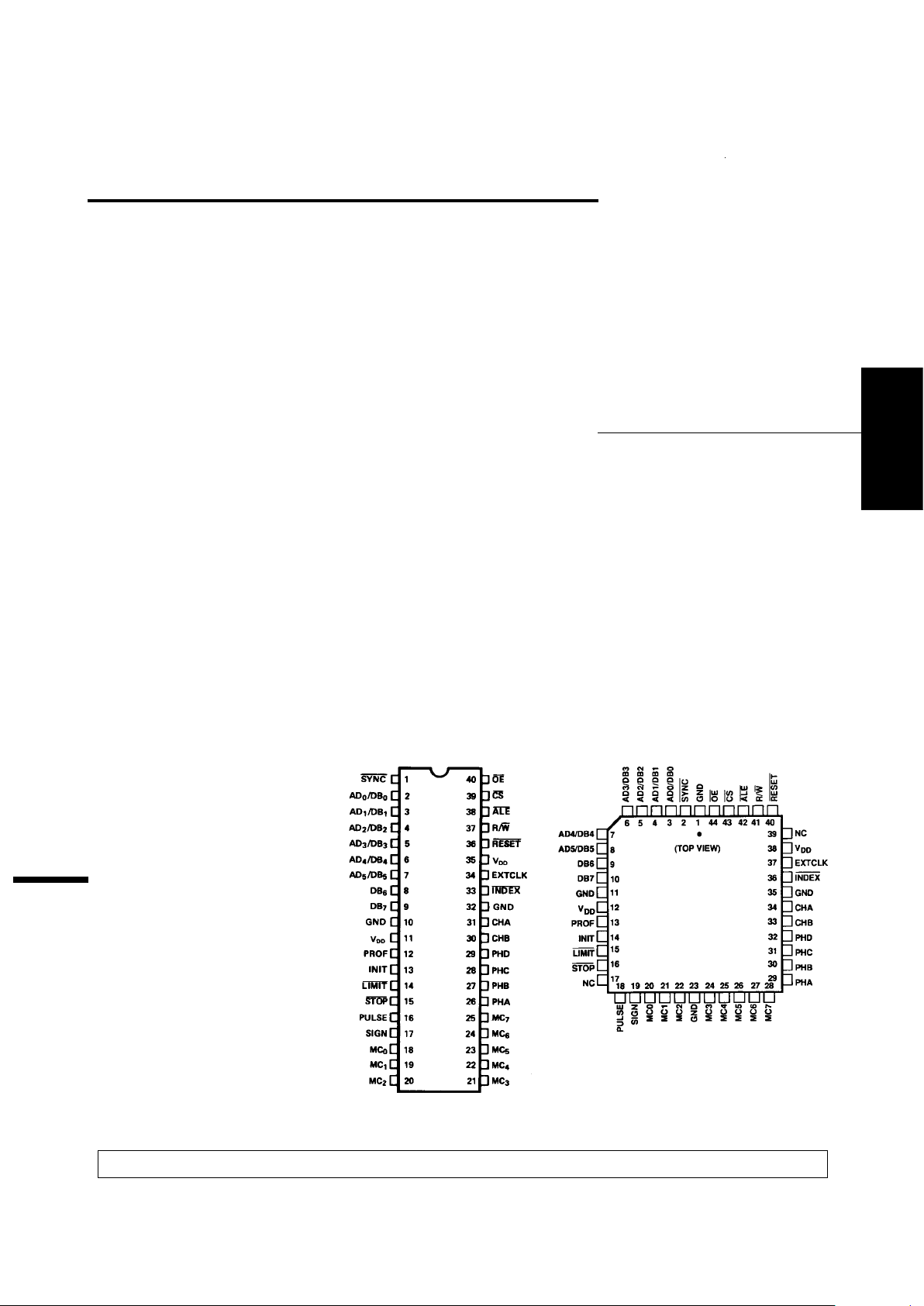
Pinouts
ESD WARNING: NORMAL HANDLING PRECAUTIONS SHOULD BE TAKEN TO AVOID STATIC DISCHARGE.
H
5965-5893E
2-140
Applications
Typical applications for the
HCTL-1100 include printers,
medical instruments, material
handling machines, and industrial
automation.
HCTL-1100 vs.
HCTL-1000
The HCTL-1100 is designed to
replace the HCTL-1000. Some
differences exist, and some
enhancements have been added.
Comparison of HCTL-1100 and HCTL-1000
Description HCTL-1100 HCTL-1000
Max. Supply Current 30 mA 180 mA
Max. Power Dissipation 165 mW 950 mW
Max. Tri-State Output
Leakage Current 150 nA 10 µA
Operating Frequency 100 kHz-2 MHz 1 MHz-2 MHz
Operating Temperature
Range -20°C to +85°C0°C to 70°C
Storage Temperature Range -55°C to +125°C-40°C to +125°C
Synchronize 2 or More ICs Yes –
Preset Actual Position
Registers Yes –
Read Flag Register Yes –
Limit and Stop Pins Must be pulled Can be left
up to VDD if floating if not
not used. used.
Hard Reset Required Recommended
PLCC Package Available Yes –
System Block Diagram
2-141
MOTION SENSING
AND CONTROL
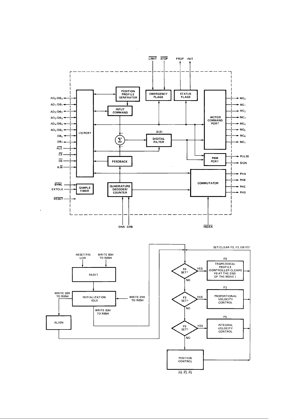
Theory of Operation
The HCTL-1100 is a general purpose motor controller which
provides position and velocity
control for DC, DC brushless and
stepper motors. The internal
block diagram of the HCTL-1100
is shown in Figure 1. The HCTL1100 receives its input commands
from a host processor and
position feedback from an
incremental encoder with quadrature output. An 8-bit bi-directional
multiplexed address/data bus
interfaces the HCTL-1100 to the
host processor. The encoder
The resident Position Profile
Generator calculates the necessary profiles for Trapezoidal Profile Control and Integral Velocity
Control. The HCTL-1100 compares the desired position (or
velocity) to the actual position (or
velocity) to compute compensated
motor commands using a programmable digital filter D(z). The
motor command is externally
available at the Motor Command
port as an 8-bit byte and at the
PWM port as a Pulse Width
Modulated (PWM) signal.
The HCTL-1100 has the capability
of providing electronic commutation for DC brushless and
stepper motors. Using the
encoder position information, the
motor phases are enabled in the
correct sequence. The commutator is fully programmable to
encompass most motor/encoder
combinations. In addition, phase
overlap and phase advance can be
programmed to improve torque
ripple and high speed performance. The HCTL-1100 contains a
number of flags including two
externally available flags, Profile
and Initialization, which allow the
user to see or check the status of
the controller. It also has two
emergency inputs, Limit and Stop,
which allow operation of the
HCTL-1100 to be interrupted
under emergency conditions.
The HCTL-1100 controller is a
digitally sampled data system.
While information from the host
processor is accepted asynchronously with respect to the
control functions, the motor
command is computed on a
discrete sample time basis. The
sample timer is programmable.
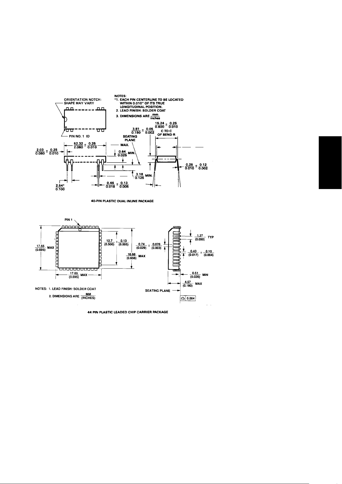
Package Dimensions
feedback is decoded into
quadrature counts and a 24-bit
counter keeps track of position.
The HCTL-1100 executes any one
of four control algorithms
selected by the user. The four
control modes are:
• Position Control
• Proportional Velocity Control
• Trapezoidal Profile Control for
point to point moves
• Integral Velocity Control with
continuous velocity profiling
using linear acceleration
4.83
0.190
1.27
0.050
±
0.15
0.006
0-15°
13.72
0.540
13.72
0.540
0.25
0.010
±
2-142
Figure 1. Internal Block Diagram.
Figure 2. Operating Mode Flowchart.

2-143
MOTION SENSING
AND CONTROL
Electrical Specifications
Absolute Maximum Ratings
Operating Temperature, T
A
...................................................................
-20°C to 85°C
Storage Temperature, T
S
......................................................................
-55°C to 125°C
Supply Voltage, V
DD
......................................................................................
-0.3 V to 7 V
Input Voltage, V
IN
.........................................................................
-0.3 V to VDD +0.3 V
Maximum Operating Clock Frequency, f
CLK
...............................................
2 MHz
DC Electrical Characteristics
VDD = 5 V ± 5%; TA = -20°C to +85°C
Parameter Symbol Min. Typ. Max. Units Test Conditions
Supply Voltage V
DD
4.75 5.00 5.25 V
Supply Current I
DD
15 30 mA
Input Leakage Current I
IN
10 100 nA VIN = 0.00 and 5.25 V
Input Pull-Up Current
SYNC PIN I
PU
- 40 ± 150 µAVIN = 0.00 V
Tristate Output Leakage I
OZ
10 -150 nA Sync, LIMIT, STOP
Current pin #35 (PDIP)
V
OUT
= -0.3 to 5.25 V
pin #38 (PLCC)
Input Low Voltage V
IL
-0.3 0.8 V
Input High Voltage V
IH
2.0 V
DD
V
Output Low Voltage V
OL
-0.3 0.4 V IOL = 2.2 mA
Output High Voltage V
OH
2.4 V
DD
VIOH = -200 µA
Power Dissipation P
D
75 165 mW
Input Capacitance C
IN
20 pF
Output Capacitance C
OUT
100 pF
2-144
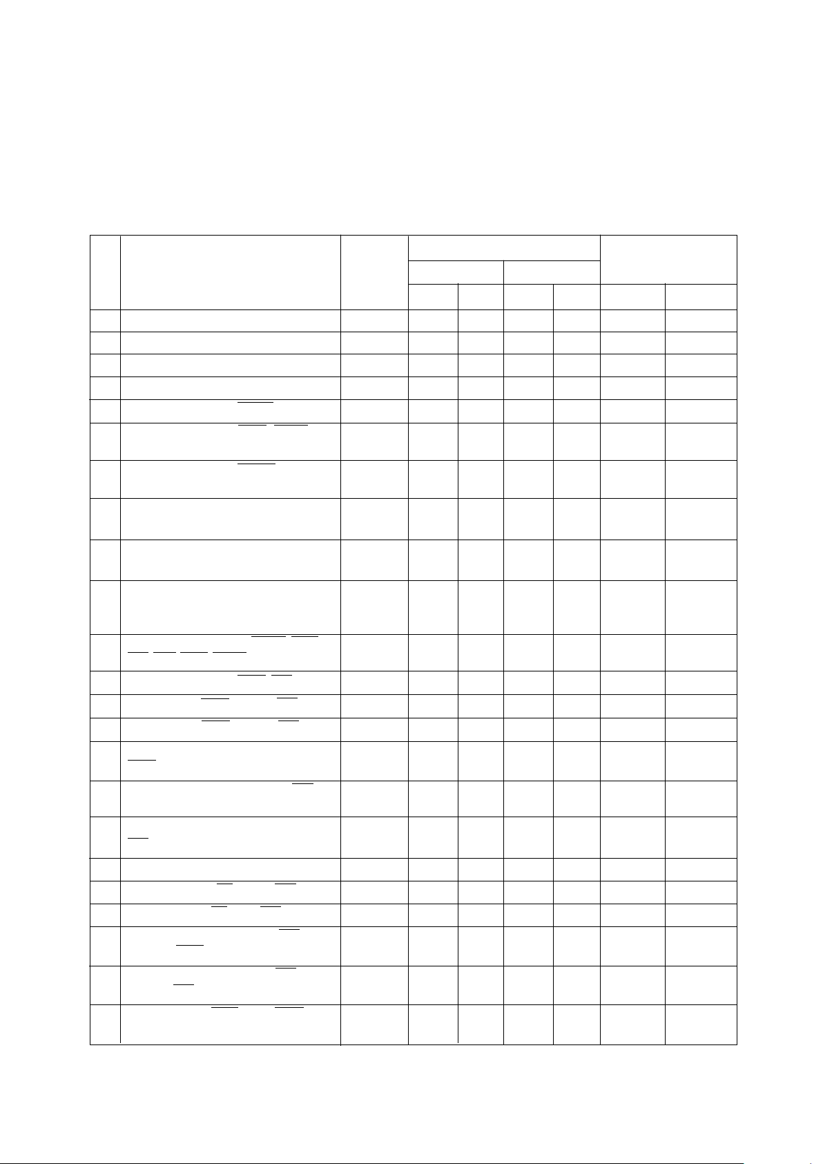
AC Electrical Characteristics
VDD = 5 V ± 5%; TA = -20°C to +85°C; Units = nsec
Clock Frequency
Formula*
2 MHz 1 MHz
ID
# Signal Symbol Min. Max. Min. Max. Min. Max.
1 Clock Period (clk) t
CPER
500 1000
2 Pulse Width, Clock High t
CPWH
230 300
3 Pulse Width, Clock Low t
CPWL
200 200 200
4 Clock Rise and Fall Time t
CR
50 50 50
5 Input Pulse Width Reset t
IRST
2500 5000 5 clk
6 Input Pulse Width Stop, Limit t
IP
600 1100 1 clk
+ 100 ns
7 Input Pulse Width Index, Index t
IX
1600 3100 3 clk
+ 100 ns
8 Input Pulse Width CHA, CHB t
IAB
1600 3100 3 clk
+ 100 ns
9 Delay CHA to CHB Transition t
AB
600 1100 1 clk
+ 100 ns
10 Input Rise/Fall Time CHA, CHB,
Index t
IABR
450 900 900 (clk
< 1 MHz)
11 Input Rise/Fall Time Reset, ALE,
CS, OE, Stop, Limit t
IR
50 50 50
12 Input Pulse Width ALE, CS t
IPW
80 80 80
13 Delay Time, ALE Fall to CS Fall t
AC
50 50 50
14 Delay Time, ALE Rise to CS Rise t
CA
50 50 50
15 Address Setup Time Before
ALE Rise t
ASR1
20 20 20
16 Address Setup Time Before CS t
ASR
20 20 20
Fall
17 Write Data Setup Time Before
CS Rise t
DSR
20 20 20
18 Address/Data Hold Time t
H
20 20 20
19 Setup Time, R/W Before CS Rise t
WCS
20 20 20
20 Hold Time, R/W After CS Rise t
WH
20 20 20
21 Delay Time, Write Cycle, CS
Rise to ALE Fall t
CSAL
1700 3400 3.4 clk
22 Delay Time, Read/Write, CS
Rise to CS Fall t
CSCS
1500 3000 3 clk
23 Write Cycle, ALE Fall to ALE
Fall For Next Write t
WC
1830 3530 3.7 clk
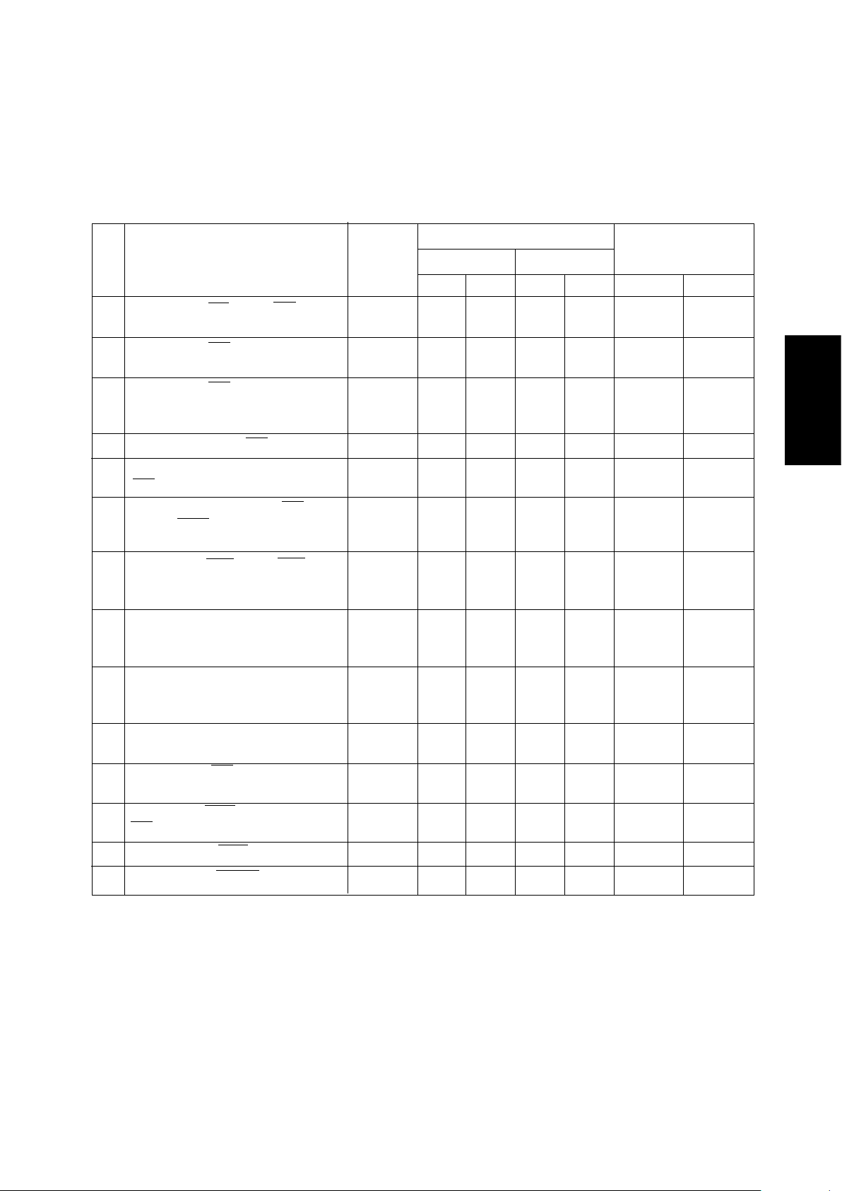
2-145
MOTION SENSING
AND CONTROL
Clock Frequency
Formula*
2 MHz 1 MHz
ID
# Signal Symbol Min. Max. Min. Max. Min. Max.
24 Delay Time, CS Rise to OE Fall t
CSOE
1700 3200 3 clk
+ 200 ns
25 Delay Time, OE Fall to Data
Bus Valid t
OEDB
100 100 100
26 Delay Time, CS Rise to Data
Bus Valid t
CSDB
1800 3300 3 clk
+ 300 ns
27 Input Pulse Width OE t
IPWOE
100 100 100
28 Hold Time, Data Held After
OE Rise t
DOEH
20 20 20
29 Delay Time, Read Cycle, CS
Rise to ALE Fall t
CSALR
1820 3320 3 clk
+ 320 ns
30 Read Cycle, ALE Fall to ALE
Fall For Next Read t
RC
1950 3450 3 clk
+ 450 ns
31 Output Pulse Width, PROF,
INIT, Pulse, Sign, PHA-PHD,
MC Port t
OF
500 1000 1 clk
32 Output Rise/Fall Time, PROF,
INIT, Pulse, Sign, PHA-PHD,
MC Port t
OR
20 150 20 150 20 150
33 Delay Time, Clock Rise to
Output Rise t
EP
20 300 20 300 20 300
34 Delay Time, CS Rising to MC
Port Valid t
CSMC
1600 3200 3.2 clk
35 Hold Time, ALE High After
CS Rise t
ALH
100 100 100
36 Pulse Width, ALE High t
ALPWH
100 100 100
37 Pulse Width, SYNC Low t
SYNC
9000 18000 18 clk
*General formula for determining AC characteristics for other clock frequencies (clk), between 100 kHz and 2 MHz.
AC Electrical Characteristics (continued).
2-146
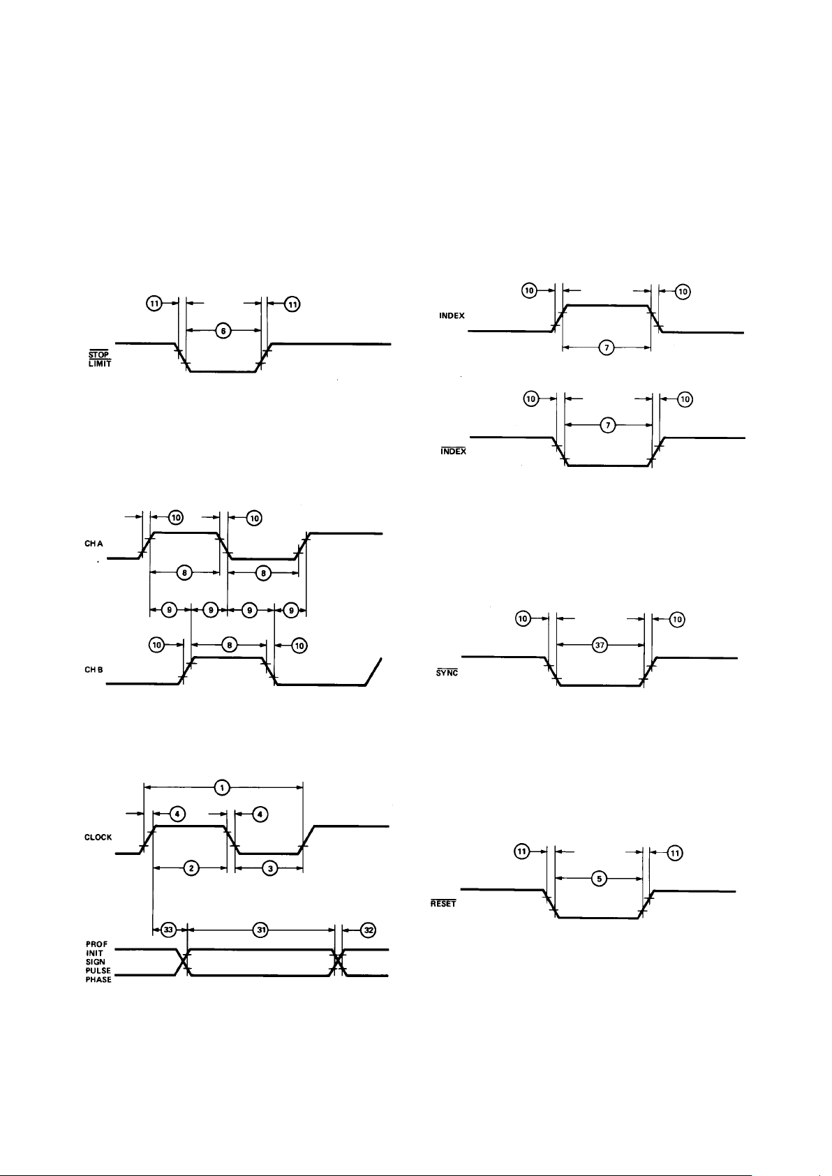
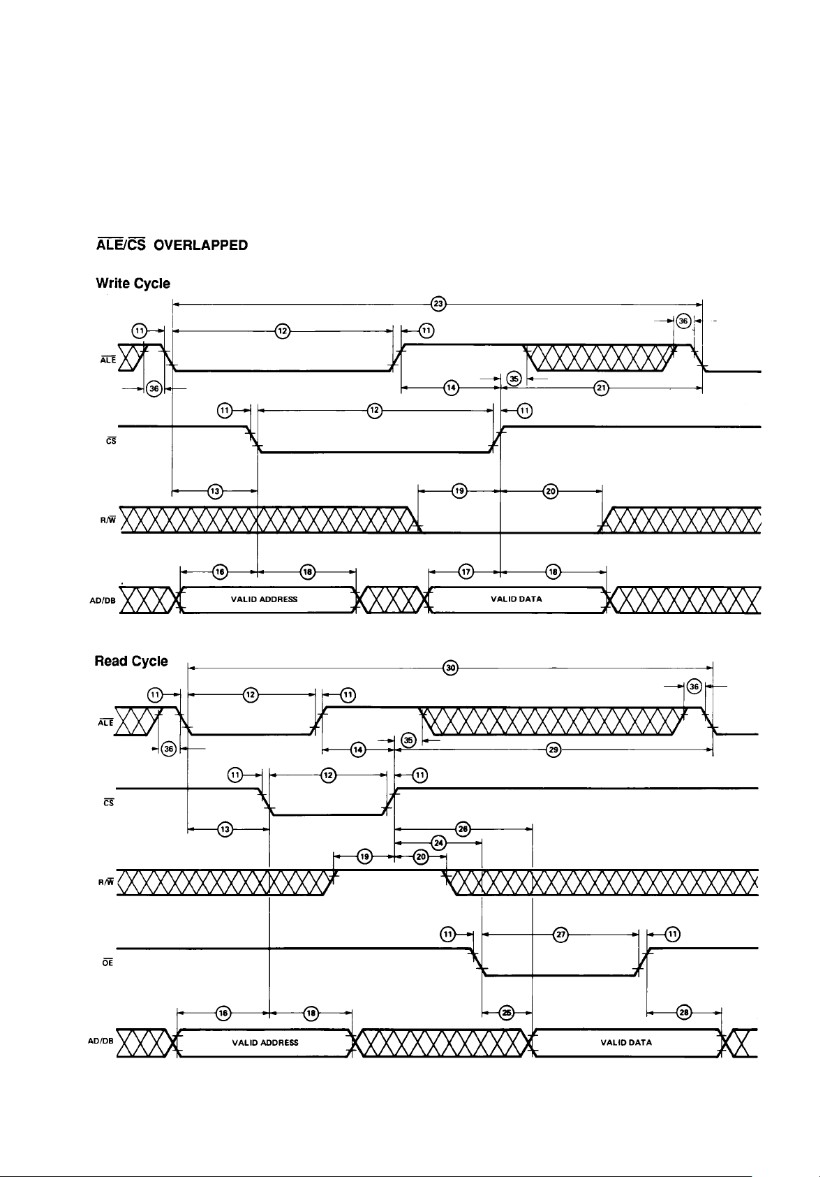
HCTL-1100 I/O Timing Diagrams
Input logic level values are the TTL Logic levels VIL = 0.8 V and VIH = 2.0 V. Output logic levels
are VOL = 0.4 V and VOH = 2.4 V.
2-147
MOTION SENSING
AND CONTROL
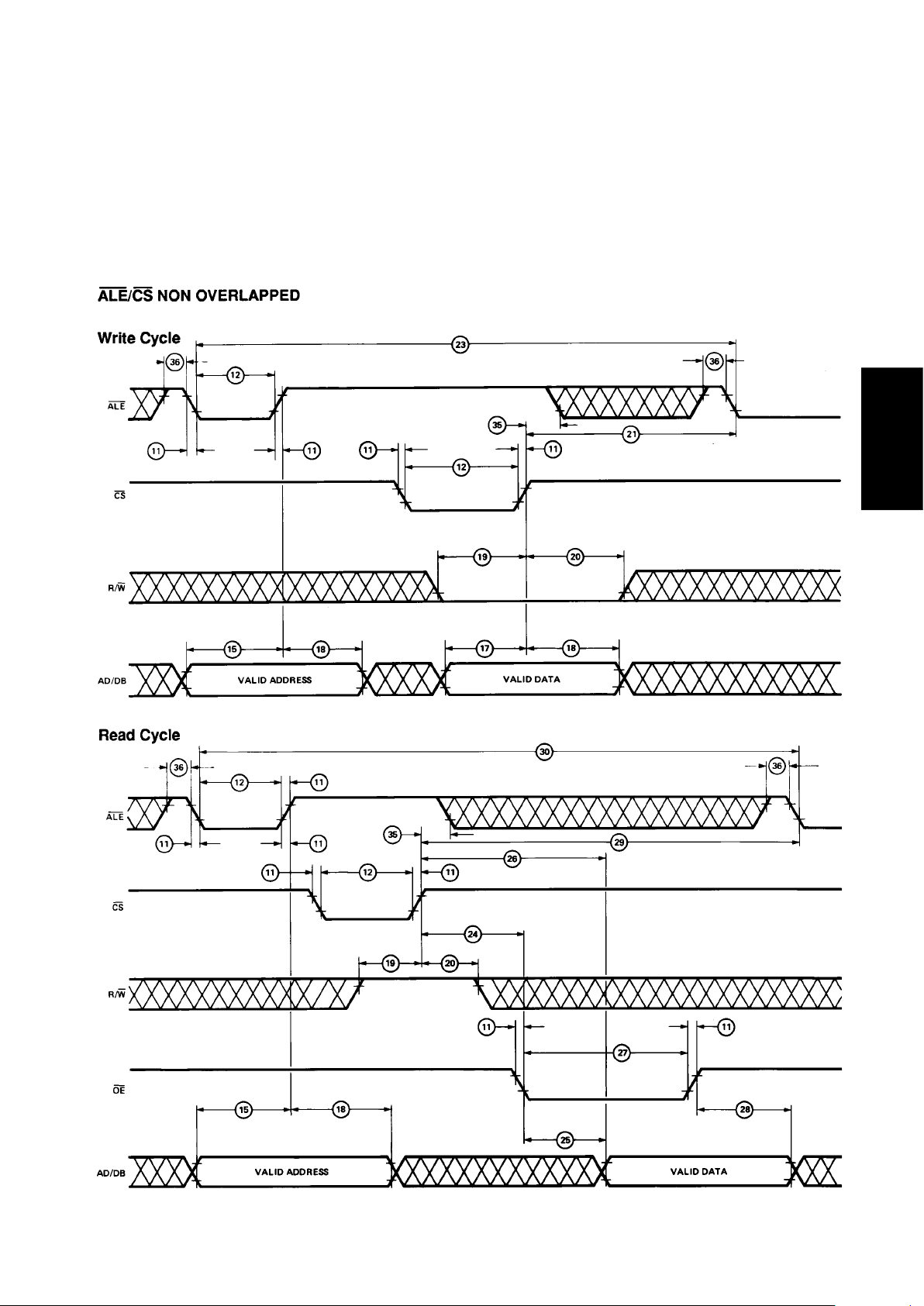
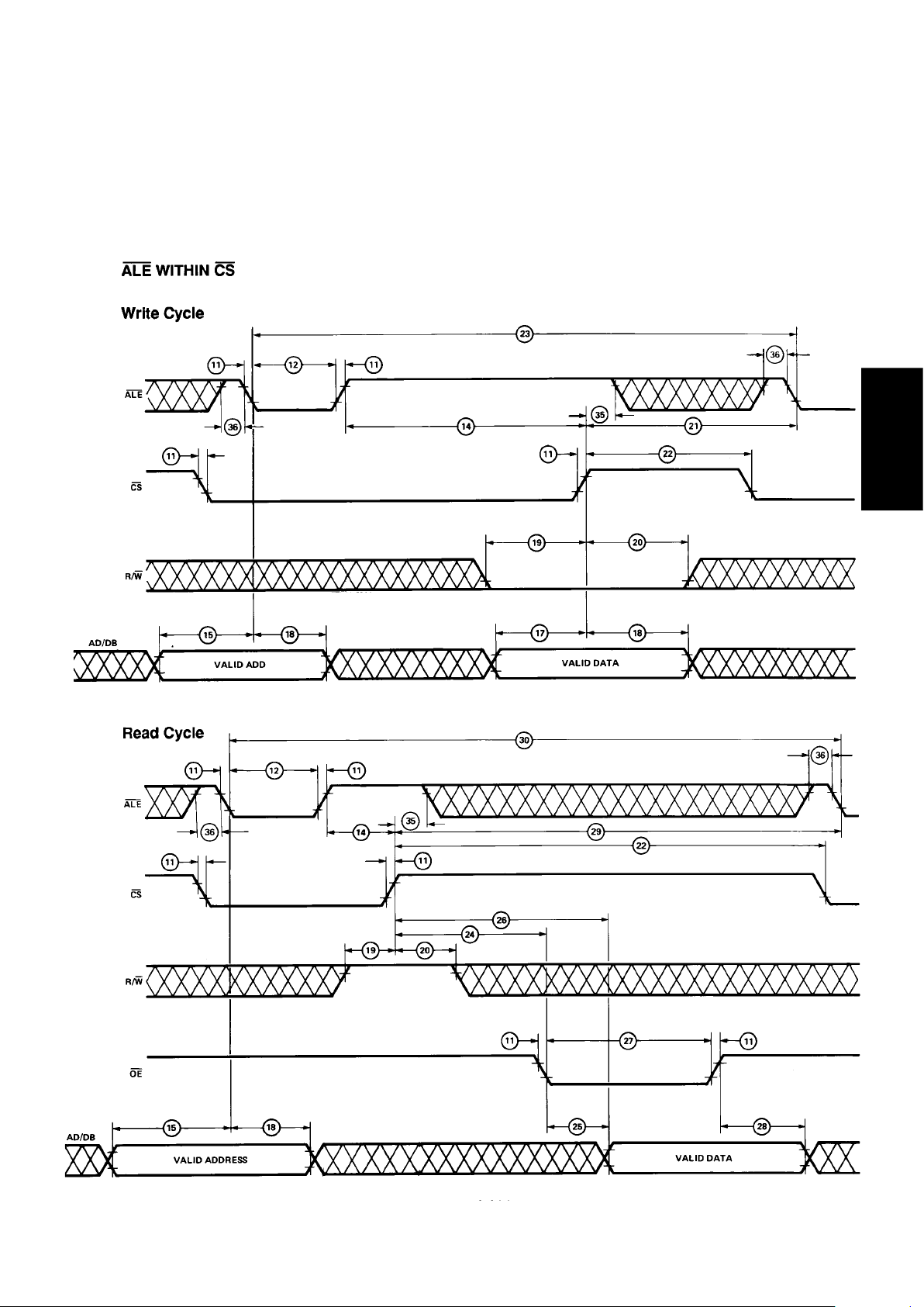
HCTL-1100 I/O Timing Diagrams
There are three different timing configurations which can be used to give the user flexibility to interface the
HCTL-1100 to most microprocessors. See the I/O interface section for more details.
2-148
HCTL-1100 I/O Timing Diagrams
2-149
MOTION SENSING
AND CONTROL
HCTL-1100 I/O Timing Diagrams
2-150
Pin Descriptions and Functions
Input/Output Pins
Pin Number
Symbol PDIP PLCC Description
AD0/DB0- 2-7 3-8 Address/Data Bus – Lower 6 bits of 8-bit I/O port which are
AD5/DB5 multiplexed between address and data.
DB6, DB7 8, 9 9, 10 Data bus – Upper 2 bits of 8-bit I/O port used for data only.
Input Signals
Pin Number
Symbol PDIP PLCC Description
CHA/CHB 31, 30 34, 33 Channel A, B – Input pins for position feedback from an incremental
shaft encoder. Two channels, A and B, 90 degrees out of phase are
required.
Index 33 36 Index Pulse – Input from the reference or index pulse of an incre-
mental encoder. Used only in conjunction with the Commutator. Either
a low or high true signal can be used with the Index pin. See Timing
Diagrams and Encoder Interface section for more detail.
R/W 37 41 Read/Write – Determines direction of data exchange for the I/O port.
ALE 38 42 Address Latch Enable – Enables lower 6 bits of external data bus into
internal address latch.
CS 39 43 Chip Select – Performs I/O operation dependent on status of R/W line.
For a Write, the external bus data is written into the internal
addressed location. For Read, data is read from an internal location
into an internal output latch.
OE 40 44 Output Enable – Enables the data in the internal output latch onto the
external data bus to complete a Read operation.
Limit 14 15 Limit Switch – An internal flag which when externally set, triggers an
unconditional branch to the Initialization/Idle mode before the next
control sample is executed. Motor Command is set to zero. Status of
the Limit flag is monitored in the Status register.
Stop 15 16 Stop Flag – An internal flag that is externally set. When flag is set
during Integral Velocity Control mode, the Motor Command is
decelerated to a stop.
Reset 36 40 Reset – A hard reset of internal circuitry and a branch to Reset mode.
ExtClk 34 37 External Clock
V
DD
11, 35 12, 38 Voltage Supply – Both VDD pins must be connected to a 5.0 volt supply.
GND 10, 32 1, 11, Circuit Ground
23, 35
SYNC 1 2 Used to synchronize multiple HCTL-1100 sample timers.
NC – 17, 39 Not connected. These pins should be left floating.

2-151
MOTION SENSING
AND CONTROL
Output Pins
Pin Number
Symbol PDIP PLCC Description
MC0-MC7 18-25 20-22, Motor Command Port – 8-bit output port which contains the digital
24-28 motor command adjusted for easy bipolar DAC interfacing. MC7 is
the most significant bit (MSB).
Pulse 16 18 Pulse – Pulse width modulated signal whose duty cycle is proportional
to the Motor Command magnitude. The frequency of the signal is
External Clock/100 and pulse width is resolved into 100 external clocks.
Sign 17 19 Sign – Gives the sign/direction of the pulse signal.
PHA-PHD 26-29 29-32 Phase A, B, C, D – Phase Enable outputs of the Commutator.
Prof 12 13 Profile Flag – Status flag which indicates that the controller is execut-
ing a profiled position move in the Trapezoidal Profile Control mode.
Init 13 14 Initialization/Idle Flag – Status flag which indicates that the controller
is in the Initialization/Idle mode.
Pin Functionality
SYNC Pin
The SYNC pin is used to synchronize two or more ICs. It is
only valid in the INIT/IDLE mode
(see Operating the HCTL-1100).
When this pin is pulled low, the
internal sample timer is cleared
and held to zero. When the level
on the pin is returned to high, the
internal sample timer instantly
starts counting down from the
programmed value.
Connecting all SYNC pins
together in the system and
pulsing the SYNC signal from the
host processor will synchronize
all controllers.
Limit Pin
This emergency-flag input is used
to disable the control modes of
the HCTL-1100. A low level on
this input pin causes the internal
Limit flag to be set. If this pin is
NOT used, it must be pulled up to
VDD. If it is not connected, the pin
could float low, and possibly
trigger a false emergency
condition.
The Limit flag, when set in any
control mode, causes the HCTL1100 to go into the Initialization/
Idle mode, clearing the Motor
Command and causing an immediate motor shutdown. When the
Limit flag is set, none of the three
control mode flags (F0, F3, or
F5) are cleared as the HCTL-1100
enters the Initialization/Idle mode.
The user should be aware that
these flags are still set before
commanding the HCTL-1100 to
re-enter one of the four control
modes from Initialization/Idle
mode.
In general, the user should clear
all control mode flags after the
limit pin has been pulled low,
then proceed.
Stop Pin
The Stop flag affects the HCTL1100 only in the Integral Velocity
Mode.
When a low level is present on
this emergency-flag input, the
internal stop flag is set. If this pin
is NOT used, it must be pulled up
to VDD. If it is not connected, the
pin could float low, and possibly
trigger a false emergency
condition.
When the STOP flag is set, the
system will come to a decelerated
stop and stay in this mode with a
command velocity of zero until
the Stop flag is cleared and a new
command velocity is specified.
Notes on Limit and Stop Flags
Stop and Limit flags are set by a
low level input at their respective
pins. The flags can only be
cleared when the input to the
corresponding pin goes high,
signifying that the emergency
condition has been corrected,
AND a write to the Status register
(R07H) is executed. That is, after
the emergency pin has been set
and cleared, the flag also must be
cleared by writing to R07H. Any
word that is written to R07H after
the emergency pin is set and
cleared will clear the emergency
flag. The lower four bits of that
word will also reconfigure the
Status register.

2-152
Encoder Input Pins (CHA,
CHB, INDEX)
The HCTL-1100 accepts TTL
compatible outputs from 2 and 3
channel incremental encoders
such as the HEDS-5XXX, 6XXX,
and 9XXX series encoders.
Channels A and B are internally
decoded into quadrature counts
which increment or decrement
the 24-bit position counter. For
example, a 500-count encoder is
decoded into 2000 quadrature
counts per revolution. The
position counter will be incremented when Channel B leads
Channel A. The Index channel is
used only for the Commutator and
its function is to serve as a
reference point for the internal
Ring Counter.
The HCTL-1100 employs an
internal 3-bit state delay filter to
remove any noise spikes from the
encoder inputs to the HCTL-1100.
This 3-bit state delay filter
requires the encoder inputs to
remain stable for three consecutive clock rising edges for an
encoder pulse to be considered
valid by the HCTL-1100’s actual
position counter (i.e., an encoder
pulse must remain at a logic level
high or low for three consecutive
clock rising edges for the HCTL1100’s actual position counter to
be incremented or decremented.)
The designer should therefore
generally avoid creating the
encoder pulses of less than 3
clock cycles.
The index signal of an encoder is
used in conjunction with the
Commutator. It resets the internal
ring counter which keeps track of
the rotor position so that no
cumulative errors are generated.
The Index pin of the HCTL-1100
also has a 3-bit filter on its input.
The Index pin is active low and
level transition sensitive. It
detects a valid high-to-low
transition and qualifies the low
input level through the 3-bit filter.
At this point, the Index signal is
internally detected by the
commutator logic. This type of
configuraiton allows an Index or
Index signal to be used to generate the reference mark for
commutator operation as long as
the AC specifications for the
Index signal are met.
Motor Command Port (MC0MC7)
The 8-bit Motor Command port
consists of register R08H whose
data goes directly to external pins
MC0-MC7. MC7 is the most
significant bit. R08H can be read
and written to, however, it should
be written to only during the
Initialization/Idle mode. During
any of the four Control modes,
the controller writes the motor
command into R08H.
This topic is further discussed in
the “Register Section” under
“Motor Command Register
R08H”.
Pulse Width Modulation
(PWM) Output Port (Pulse,
Sign)
The PWM port consists of the
Pulse and Sign pins. The PWM
port outputs the motor command
as a pulse width modulated signal
with the correct polarity. This
topic is further discussed in the
“Register Section” under “PWM
Motor Command Register R09H”.
Trapezoid Profile Pin (Prof)
The Trapezoid Profile Pin is
internally connected to software
flag bit 4 in the Status Register.
This flag is also represented by bit
0 in the Flag Register (R00H).
See the “Register Section” for
more information. Both the Pin
and the Flag indicate the status of
a trapezoid profile move. When
the HCTL-1100 begins a
trapezoid move, this flag is set by
the controller (a high level
appears on the pin), indicating
the move is in progress. When the
HCTL-1100 finishes the move,
this flag is cleared by the
controller.
Note that the instant the flag is
cleared may not be the same
instant the motor stops. The flag
indicates the completion of the
command profile, not the actual
profile. If the motor is stalled
during the move, or cannot
physically keep up with the move,
the flag will be cleared before the
move is finished.
INIT/IDLE Pin (INIT)
This pin indicates that the HCTL1100 is in the INIT/IDLE mode,
waiting to begin control. This pin
is internally connected to the
software flag bit 5 in the Status
Register R07H. This flag is also
represented by bit 1 in the Flag
Register (R00H) (See the
“Register Section” for more
information).
Commutator Pins (PHA-PHD)
These pins are connected only
when using the commutator of the
HCTL-1100 to drive a brushless
motor or step motor. The four
pins can be programmed to
energize each winding on a
multiphase motor.

2-153
MOTION SENSING
AND CONTROL
Figure 3. Register Block Diagram.
Operation of the
HCTL-1100
Registers
The HCTL-1100 operation is
controlled by a bank of 64 8-bit
registers, 35 of which are user
accessible. These registers
contain command and configuration information necessary to
properly run the controller chip.
The 35 user-accessible registers
are listed in Tables 1 and 2. The
register number is also the
address. A functional block
diagram of the HCTL-1100 which
shows the role of the useraccessible registers is also
included in Figure 3. The other 29
registers are used by the internal
CPU as scratch registers and
should not be accessed by the
user.

2-154
Table 1. Register Reference By Mode
Register
User
Hex Dec. Function Data Type
[1]
Access
General Control
R00H R00D Flag Register r/w
R05H R05D Program Counter scalar r/w
R07H R07D Status Register - r/w
[2]
R0FH R15D Sample Timer scalar r/w
R12H R18D Read Actual Position MSB 2’s Complement r
[4]
R13H R19D Read Actual Position 2’s Complement r
[4]/w[5]
R14H R20D Read Actual Position LSB 2’s Complement r
[4]
R15H R21D Preset Actual Position MSB 2’s Complement w
[8]
R16H R22D Preset Actual Position 2’s Complement w
[8]
R17H R23D Preset Actual Position LSB 2’s Complement w
[8]
Output Registers
R07H R07D Sign Reversal Inhibit - r/w
[2]
R08H R08D 8 bit Motor Command 2’s Complement+80H r/w
R09H R09D PWM Motor Command 2’s Complement r/w
Filter Registers
R20H R32D Filter Zero, A scalar r/w
R21H R33D Filter Pole, B scalar r/w
R22H R34D Gain, K scalar r/w
Commutator Registers
R07H R07D Status Register - r/w
[2]
R18H R24D Commutator Ring scalar
[6,7]
r/w
R19H R25D Velocity Timer scalar w
R1AH R26D X scalar
[6,7]
r/w
R1BH R27D Y Phase Overlap scalar
[6,7]
r/w
R1CH R28D Offset 2’s Complement
[7]
r/w
R1FH R31D Max. Phase Advance scalar
[6,7]
r/w
Position Control Mode
R00H R00D Flag Register - r/w
R12H R18D Read Actual Position MSB 2’s Complement r
[4]
R13H R19D Read Actual Position 2’s Complement r
[4]/w[5]
R14H R20D Read Actual Position LSB 2’s Complement r
[4]
R0CH R12D Command Position MSB 2’s Complement r/w
[3]
R0DH R13D Command Position 2’s Complement r/w
[3]
R0EH R14D Command Position LSB 2’s Complement r/w
[3]

2-155
MOTION SENSING
AND CONTROL
Table 1. (continued).
Register
User
Hex Dec. Function Data Type Access
Trapezoid Profile Control Mode
R00H R00D Flag Register - r/w
R07H R07D Status Register - r/w
[2]
R12H R18D Read Actual Position MSB 2’s Complement r
[4]
R13H R19D Read Actual Position 2’s Complement r
[4]/w[5]
R14H R20D Read Actual Position LSB 2’s Complement r
[4]
R29H R41D Final Position LSB 2’s Complement r/w
R2AH R42D Final Position 2’s Complement r/w
R2BH R43D Final Position MSB 2’s Complement r/w
R26H R38D Acceleration LSB scalar r/w
R27H R39D Acceleration MSB scalar
[6]
r/w
R28H R40D Maximum Velocity scalar
[6]
r/w
Integral Velocity Mode
R00H R00D Flag Register - r/w
R12H R18D Read Actual Position MSB 2’s Complement r
[4]
R13H R19D Read Actual Position 2’s Complement r
[4]/w[5]
R14H R20D Read Actual Position LSB 2’s Complement r
[4]
R26H R38D Acceleration LSB scalar r/w
R27H R39D Acceleration MSB scalar
[6]
r/w
R3CH R60D Command Velocity 2’s Complement r/w
Proportional Velocity Mode
R00H R00D Flag Register - r/w
R12H R18D Read Actual Position MSB 2’s Complement r
[4]
R13H R19D Read Actual Position 2’s Complement r
[4]/w[5]
R14H R20D Read Actual Position LSB 2’s Complement r
[4]
R23H R35D Command Velocity LSB 2’s Complement r/w
R24H R36D Command Velocity MSB 2’s Complement r/w
R34H R52D Actual Velocity LSB 2’s Complement r
R35H R53D Actual Velocity MSB 2’s Complement r
Notes:
1. Consult appropriate section for data format and use.
2. Upper 4 bits are read only.
3. Writing to R0EH (LSB) latches all 24 bits.
4. Reading R14H (LSB) latches data in R12H and R13H.
5. Writing to R13H clears Actual Position Counter to zero.
6. The scalar data is limited to positive numbers (00H to 7FH).
7. The commutator registers (R18H, R1CH, R1FH) have further limits which are discussed in the Commutator section of this data sheet.
8. Writing to R17H (R23D) latches all 24 bits (only in INIT/IDLE mode).

2-156
Table 2. Register Reference Table by Register Number
Register
User
Hex Dec. Function Mode Used Data Type Access
R00H R00D Flag Register All – r/w
R05H R05D Program Counter All scalar w
R07H R07D Status Register All – r/w
[2]
R08H R08D 8 bit Motor Command Port All 2’s complement
+ 80H r/w
R09H R09D PWM Motor Command Port All 2’s complement r/w
R0CH R12D Command Position (MSB) All except Proportional 2’s complement r/w
[3]
Velocity
R0DH R13D Command Position All except Proportional 2’s complement r/w
[3]
Velocity
R0EH R14D Command Position (LSB) All except Proportional 2’s complement r/w
[3]
Velocity
R0FH R15D Sample Timer All scalar r/w
R12H R18D Read Actual Position (MSB) All 2’s complement r
[4]
R13H R19D Read Actual Position All 2’s complement r
[4]/w[5]
R14H R20D Read Actual Position (LSB) All 2’s complement r
[4]
R15H R21D Preset Actual Position (MSB) INIT/IDLE 2’s complement w
[8]
R16H R22D Preset Actual Position INIT/IDLE 2’s complement w
[8]
R17H R23D Preset Actual Position (LSB) INIT/IDLE 2’s complement w
[8]
R18H R24D Commutator Ring All scalar
[6,7]
r/w
R19H R25D Commutator Velocity Timer All scalar w
R1AH R26D X All scalar
[6]
r/w
R1BH R27D Y Phase Overlap All scalar
[6]
r/w
R1CH R28D Offset All 2’s complement
[7]
r/w
R1FH R31D Maximum Phase Advance All scalar
[6,7]
r/w
R20H R32D Filter Zero, A All except Proportional scalar r/w
Velocity
R21H R33D Filter Pole, B All except Proportional scalar r/w
Velocity
R22H R34D Gain, K All scalar r/w
R23H R35D Command Velocity (LSB) Proportional Velocity 2’s complement r/w
R24H R36D Command Velocity (MSB) Proportional Velocity 2’s complement r/w
R26H R38D Acceleration (LSB) Integral Velocity and scalar r/w
Trapezoidal Profile
R27H R39D Acceleration (MSB) Integral Velocity and scalar
[6]
r/w
Trapezoidal Profile
R28H R40D Maximum Velocity Trapezoidal Profile scalar
[6]
r/w
R29H R41D Final Position (LSB) Trapezoidal Profile 2’s complement r/w
R2AH R42D Final Position Trapezoidal Profile 2’s complement r/w
R2BH R43D Final Position (MSB) Trapezoidal Profile 2’s complement r/w
R34H R52D Actual Velocity (LSB) Proportional Velocity 2’s complement r
R35H R53D Actual Velocity (MSB) Proportional Velocity 2’s complement r
R3CH R60D Command Velocity Integral Velocity 2’s complement r/w
Notes:
1. Consult appropriate section for data format and use.
2. Upper 4 bits are read only.
3. Writing to R0EH (LSB) latches all 24 bits.
4. Reading R14H (LSB) latches data in R12H and R13H.
5. Writing to R13H clears Actual Position Counter to zero.
6. The scalar data is limited to positive numbers (00H to 7FH).
7. The commutator registers (R18H, R1CH, R1FH) have further limits which are discussed in the Commutator section of this data sheet.
8. Writing to R17H (R23D) latches all 24 bits (only in INIT/IDLE mode).

2-157
MOTION SENSING
AND CONTROL
motor by using the commutator.
(See “Offset register” description
in the “Commutator section.”)
F5–Integral Velocity Control – set
by the user to specify Integral
Velocity Control. Also set and
cleared by the HCTL-1100 during
execution of the Trapezoidal
Profile mode. This is transparent
to the user except when the Limit
flag is set (see “Emergency Flags”
section).
Writing to the Flag Register
When writing to the flag register,
only the lower four bits are used.
Bit 3 indicates whether to set or
clear a certain flag, and bits
0,1,and 2 indicate the desired
flag. The following table shows
the bit map of the Flag register:
Bit Number Function
7-4 Don’t Care
3 1 = set
0 = clear
2 AD2
1 AD1
0 AD0
The following table outlines the
possible writes to the Flag
Register:
Flag SET CLEAR
F0 08H 00H
F1 - F2 0AH 02H
F3 0BH 03H
F4 0CH 04H
F5 0DH 05H
Reading the Flag Register
Reading register R00H returns
the status of the flags in bits 0 to
5. For example, if bit 0 is set
(logic 1), then flag F0 is set. If bit
4 is set, then flag F4 is set. If bits
0 and 5 are set, then both flags F0
and F5 are set.
The following table outlines the
Flag Register Read:
Flag
Bit (1 = set)
Number (0 = clear)
8-6 Don’t Care
5F5
4F4
3F3
2F2
1F1
0F0
Notes:
1. A soft reset (writing 00H to R05H) will
not reset the flags in the flag register. A
hard reset (RESET pin low) is required
to reset all the flags. The flags can also
be reset by writing the proper word to
the Flag register as explained above.
2. While in Trapezoid Profile Mode, Flag
F0 will be set, and Flag F5 may be set.
F5 is used for internal purposes. Both
flags will be cleared at the end of the
profile.
Program Counter Register
(R05H)
The Program Counter, which is a
write-only register, executes the
preprogrammed functions of the
controller. The program counter
is used along with the control
flags F0, F3, and F5 in the Flag
register (R00H) to change control
modes. The user can write any of
the following four commands to
the Program Counter.
Value
written
to R05H Action
00H Software Reset
01H Enter Init/Idle Mode
02H Enter Align Mode
(only from INIT/
IDLE Mode)
03H Enter Control Mode
(only from INIT/
IDLE Mode)
These Commands are discussed in
more detail in the “Operating
Modes” section.
Register Descriptions –
General Control, Output,
Filter, and Commutator
Flag Register (R00H)
The Flag register contains flags
F0 through F5. This register is a
read/write register. Each flag is
set and cleared by writing an 8-bit
data word to R00H. When writing
to R00H, the upper four bits are
ignored by the HCTL-1100, bits
0,1,2 specify the flag address, and
bit 3 specifies whether to set
(bit=1) or clear (bit=0) the
addressed flag.
Flag Descriptions
F0–Trapezoidal Profile Flag – set
by the user to execute Trapezoidal Profile Control. The flag is
reset by the controller when the
move is completed. The status of
F0 can be monitored at the Profile
pin and in Status register R07H
bit 4.
F1–Initialization/Idle Flag – set/
cleared by the HCTL-1100 to
indicate execution of the
Initialization/Idle mode. The
status of F1 can be monitored at
the Initialization/Idle pin and in
bit 5 of the Status register
(R07H). The user should not
attempt to set or clear F1.
F2–Unipolar Flag – set/cleared by
the user to specify Bipolar (clear)
or Unipolar (set) mode for the
Motor Command port.
F3–Proportional Velocity Control
Flag – set by the user to specify
Proportional Velocity control.
F4–Hold Commutator flag – set/
cleared by the user or automatically by the Align mode.
When set, this flag inhibits the
internal commutator counters to
allow open loop stepping of a

2-158
Motor Command Register
(R08H)
The 8-bit Motor Command Port
consists of register R08H. The
register is connected to external
pins MC0-MC7. MC7 is the most
significant bit. R08H can be read
and written to; however, it should
be written to only in the
Initialization/Idle mode. During
any of the four control modes, the
HCTL-1100 writes values to
register R08H.
The Motor Command Port
operates in two modes, bipolar
and unipolar, when under control
of internal software. Bipolar mode
allows the full range of values in
R08H (-128D to +127D). The
data written to the Motor
Command Port by the control
algorithms is the internally
computed 2’s-complement motor
command with an 80H offset
added. This allows direct interfacing to a DAC. Connecting the
Motor Command Port to a DAC,
Bipolar mode allows the full
voltage swing (positive and
negative).
Unipolar mode functions such
that with the same DAC circuit,
the motor command output is
restricted to positive values
(80H to FFH) when in a control
mode. Unipolar mode is used with
multi-phase motors when the
commutator controls the direction
of movement. (If needed, the Sign
pin could be used to indicate
direction). In Unipolar mode, the
user can still write a negative
value to R08H in INIT/IDLE
mode.
Unipolar mode or Bipolar mode is
programmed by setting or
clearing flag F2 in the Flag
Register R00H.
Internally, the HCTL-1100
operates on data of 24, 16 and 8bit lengths to produce the
8-bit motor command, available
externally. Many times the
computed motor command will be
greater than 8 bits. At this point,
the motor command is saturated
by the controller. The saturated
value output by the controller is
not the full scale value 00H
(00D), or FFH (255D). The
saturated value is adjusted to 0FH
(15D) (negative saturation) and
F0H (240D) (positive saturation).
Saturation levels for the Motor
Command port are in Figure 4.
Table 3. Status Register
Status Bit Function
0 PWM Sign Reversal Inhibit
0 = off
1 = on
1 Commutator Phase Configuration
0 = 3 phase
1 = 4 phase
2 Commutator Count Configuration
0 = quadrature
1 = full
3 Should always be set to 0
4 Trapezoidal Profile Flag F0
1 = in Profile Control
5 Initialization/Idle Flag F1
1 = in Initialization/Idle Mode
6 Stop Flag
0 = set (Stop triggered)
1 = cleared (no Stop)
7 Limit Flag
0 = set (Limit triggered)
1 = cleared (no Limit)
Status Register (R07H)
The Status register indicates the
status of the HCTL-1100. Each bit
decodes into one signal. All 8 bits
are user readable and are decoded
as shown below. Only the lower 4
bits can be written to by the user
to configure the HCTL-1100. To
set or clear any of the lower 4
bits, the user writes an 8-bit word
to R07H. The upper 4 bits are
ignored. Each of the lower 4 bits
directly sets/clears the corresponding bit of the Status register
as shown below. For example,
writing XXXX0101 to R07H sets
the PWM Sign Reversal Inhibit,
sets the Commutator Phase
Configuration to “3 Phase,” and
sets the Commutator Count
Configuration to “full.”

2-159
MOTION SENSING
AND CONTROL
PWM Motor Command
Register (R09H)
The PWM port outputs the motor
command as a pulse width
modulated signal with the correct
sign of polarity. The PWM port
consists of the Pulse and Sign
pins and R09H.
The PWM signal at the Pulse pin
has a frequency of External
Clock/100 and the duty cycle is
(–40D) gives a 40% duty cycle
signal at the Pulse pin and forces
the Sign pin high. Data outside
the 64H (+100D) to 9CH (–
100D) linear range gives 100%
duty cycle. R09H can be read and
written to. However, the user
should only write to R09H when
the controller is in the Initialization/Idle mode.
Figure 5 shows the PWM output
versus the internal motor
command.
Figure 4. Motor Command Port Output.
resolved into the 100 clocks. (For
example, a 2 MHz clock gives a
20 KHz PWM frequency.)
The Sign pin gives the polarity of
the command. Low output on Sign
pin is positive polarity.
The 2’s-complement contents of
R09H determine the duty cycle
and polarity of the PWM
command. For example, D8H

2-160
When any Control mode is being
executed, the unadjusted internal
2’s-complement motor command
is written to R09H. Because of the
hardware limit on the linear range
(64H to 9CH, ± 100D), the PWM
port saturates sooner than the 8bit Motor Command port (00H to
FFH, +127D to –128D). When
the internal motor command
saturates above 8 bits, the PWM
port is saturated to the full
± 100% duty cycle level. Figure 5
shows the actual values inside the
PWM port. Note that the Unipolar
flag, F2, does not affect the PWM
port.
For commutation of brushless
motors with the PWM port, only
use the Pulse pin from the PWM
port as the commutator already
contains sign information. (See
Figure 9.)
The PWM port has an option that
can be used with H-bridge type
amplifiers. The option is Sign
Reversal Inhibit, which inhibits
the Pulse output for one PWM
period after a sign polarity
reversal. This allows one pair of
transistors to turn off before
others are turned on and thereby
avoids a short across the power
supply. Bit 0 in the Status register
(R07H) controls the Sign Reversal
Figure 6. Sign Reversal Inhibit.
Figure 5. PWM Port Output.

2-161
MOTION SENSING
AND CONTROL
In Position Control, Integral
Velocity Control, and Trapezoidal
Profile Control the digital filter is
implemented in the time domain
as shown below:
MCn = (K/4)(Xn) –
[(A/256)(K/4)(X
n–1
) +
(B/256)(MC
n-1
)] [2]
where:
n = current sample time
n-1 = previous sample time
MCn = Motor Command Output
at n
MC
n-1
= Motor Command
Output at n-1
Xn = (Command Position –
Actual Position) at n
X
n-1
= (Command Position –
Actual Position) at n-1
In Proportional Velocity control
the digital compensation filter is
implemented in the time domain
as:
MCn = (K/4)(Yn) [3]
where:
Yn = (Command Velocity –
Actual Velocity) at n
For more information on system
sampling times, bandwidth, and
stability, please consult HewlettPackard Application Note 1032,
Design of the HCTL-1000’s
Digital Filter Parameters by the
Combination Method.
Inhibit option. Figure 6 shows the
output of the PWM port when Bit
0 is set.
Actual Position Registers
Read, Clear: R12H,R13H,R14H
Preset : R15H,R16H,R17H
The Actual Position Register is
accessed by two sets of registers
in the HCTL-1100. When reading
the Actual Position from the
HCTL-1100, the host processor
will read Registers R12H(MSB),
R13H, and R14H(LSB). When
presetting the Actual Position
Register, the processor will write
to Registers R15H(MSB), R16H,
and R17H(LSB).
When reading the Actual Position
registers, the order should be
R14H, R13H, R12H. These
registers are latched, such that,
when reading Register R14H, all
three bytes will be latched so that
count data does not change while
reading three separate bytes.
When presetting the Actual
Position Register, write to R15H
and R16H first. When R17H is
written to, all three bytes are
simultaneously loaded into the
Actual Position Register.
Note that presetting the Actual
Position Registers is only allowed
while the HCTL-1100 is in INIT/
IDLE mode.
The Actual Position Registers can
be simultaneously cleared at any
time by writing any value to
R13H.
Digital Filter Registers
Zero (A) R20H
Pole (B) R21H
Gain (K) R22H
All control modes use some part
of the programmable digital filter
D(z) to compensate for closed
loop system stability. The compensation D(z) has the form:
A
K z – –––
256
D(z) = ––––––––––– [1]
B
4 z + –––
256
where:
z = the digital domain operator
K = digital filter gain (R22H)
A = digital filter zero (R20H)
B = digital filter pole (R21H)
The compensation is a first-order
lead filter which in combination
with the Sample Timer T (R0FH)
affects the dynamic step response
and stability of the control
system. The Sample Timer, T,
determines the rate at which the
control algorithm gets executed.
All parameters, A, B, K, and T, are
8-bit scalars that can be changed
by the user any time.
As shown in equations [2] and
[3], the digital filter uses
previously sampled data to
calculate D(z). This old internally
sampled data is cleared when the
Initialization/Idle mode is
executed.

2-162
Sample Timer Register (R0FH)
The contents of this register set
the sampling period of the HCTL-
1100. The sampling period is:
t = 16(T+1)(1/frequency of the
external clock) [4]
where:
T = contents of register R0FH
The Sample Timer has a limit on
the minimum allowable sample
time depending on the control
mode being executed. The limits
are given in Table 4 below.
The minimum value limits are to
make sure the internal programs
have enough time to complete
proper execution.
The maximum value of T (R0FH)
is FFH (255D). With a 2 MHz
clock, the sample time can vary
from 64 µsec to 2048 µsec. With
a 1 MHz clock, the sample time
can vary from 128 µsec to 4096
µsec.
Digital closed-loop systems with
slow sampling times have lower
stability and a lower bandwidth
than similar systems with faster
sampling times. To keep the
system stability and bandwidth as
high as possible the HCTL-1100
should typically be programmed
with the fastest sampling time
Table 4.
R0FH Contents
Control Mode Minimum Limit
Position Control 07H(07D)
Proportional Velocity Control 07H(07D)
Trapezoidal Profile Control 0FH(15D)
Integral Velocity Control 0FH(15D)
possible. This rule of thumb must
be balanced by the needs of the
velocity range to be controlled.
Velocities are specified to the
HCTL-1100 in terms of
quadrature encoder counts per
sample time. The faster the
sampling time, the higher the
slowest possible speed.
Hardware Description
The Sample Timer consists of a
buffer and a decrement counter.
Each time the counter reaches
00H, the Sampler Timer Value T
(value written to R0FH) is loaded
from the buffer into the counter,
which immediately begins to
decrement from T.
Writing to the Sample Timer
Register
Data written to R0FH will be
latched into the internal buffer
and used by the counter after it
completes the present sample
time cycle by decrementing to
00H. The next sample time will
use the newly written data.
Reading the Sample Timer
Register
Reading R0FH gives the values
directly from the decrementing
counter. Therefore, the data read
from R0FH will have a value
anywhere between T and 00H,
depending where in the sample
time cycle the counter is.
Example –
1. On reset, the value of the timer
is pre-set to 40H.
2. Reading R0FH shows
3EH . . . 2BH . . . 08H . . .
3CH . . .
Synchronizing Multiple Axes
Synchronizing multiple axes with
HCTL-1100s can be achieved by
using the SYNC pin as explained
in the Pin Discussion section.
Some users may not only want to
synchronize several HCTL-1100s
but also follow custom profiles for
each axis. To do this, the user
may need to write a new
command position or command
velocity during each sample time
for the duration of the profile. In
this case, data written to the
HCTL-1100 has to be coordinated
with the Sample Timer. This is so
that only one command position
or velocity is received during any
one sample period, and that it is
written at the proper time within
a sample period.
At the beginning of each sample
period, the HCTL-1100 is
performing calculations and
executions. New command
positions and velocities should
not be written to the HCTL-1100
during this time. If they are, the
calculations may be thrown off
and cause unpredictable control.
The user can read the Sample
Timer Register to avoid writing
too early during a sample period.
Since the Sample Timer Register
continuously counts down from
its programmed value, the user
can check if enough time has
passed in the sample period to
insure the completion of the
internal calculations. The length
of time needed by the HCTL-1100

2-163
MOTION SENSING
AND CONTROL
to do its calculations is given by
the Minimum Limits of R0FH
(Sample Timer Register) as shown
in Table 4. For Position Control
Mode, the user should wait for the
Sample Timer to count down 07H
from its programmed value before
writing the next command
position or velocity. If the
programmed sample timer value
is 39H, wait until the Sample
Timer Register reads 32H.
Writing between 32H and 00H
will make the command information available for the next sample
period.
Commutator
Status Register (R07H)
Commutator Ring (R18H)
X Register (R1AH)
Y Phase Overlap (R1BH)
Offset (R1CH)
Max. Phase Advance (R1FH)
Velocity Timer (R19H)
The commutator is a digital state
machine that is configured by the
user to properly select the phase
sequence for electronic
commutation of multiphase
motors. The Commutator is
designed to work with 2, 3, and 4phase motors of various winding
configurations and with various
encoder counts. Along with
providing the correct phase
enable sequence, the Commutator
provides programmable phase
overlap, phase advance, and
phase offset.
Phase overlap is used for better
torque ripple control. It can also
be used to generate unique state
sequences which can be further
decoded externally to drive more
complex amplifiers and motors.
Phase advance allows the user to
compensate for the frequency
characteristics of the motor/
amplifier combination. By
advancing the phase enable
command (in position), the delay
in reaction of the motor/amplifier
combination can be offset and
higher performance can be
achieved.
Phase offset is used to adjust the
alignment of the commutator
output with the motor torque
curves. By correctly aligning the
HCTL-1100’s commutator output
with the motor’s torque curves,
maximum motor output torque
can be achieved.
The inputs to the Commutator are
the three encoder signals,
Channel A, Channel B, and Index,
and the configuration data stored
in registers.
Figure 7. Index Pulse Alignment to Motor Torque Curves.
The Commutator uses both
channels and the index pulse of
an incremental encoder. The
index pulse of the encoder must
be physically aligned to a known
torque curve location because it is
used as the reference point of the
rotor position with respect to the
Commutator phase enables.
The index pulse should be
permanently aligned during motor
encoder assembly to the last
motor phase. This is done by
energizing the last phase of the
motor during assembly and
permanently attaching the
encoder codewheel to the motor
shaft such that the index pulse is
active as shown in Figures 7
and 8. Fine tuning of alignment
for commutation purposes is done
electronically by the Offset
register (R1CH) once the complete control system is set up.

2-164
Figure 9. PWM Interface to Brushless DC Motors.
Each time an index pulse occurs,
the internal commutator ring
counter is reset to 0. The ring
counter keeps track of the current
position of the rotor based on the
encoder feedback. When the ring
counter is reset to 0, the
Commutator is reset to its origin
(last phase going low, Phase A
going high) as shown in
Figure 10.
Figure 10. Commutator Configuration.
Figure 8. Codewheel Index Pulse Alignment.
The output of the Commutator is
available as PHA, PHB, PHC, and
PHD. The HCTL-1100’s
commutator acts as the electrical
equivalent of the mechanical
brushes in a motor. Therefore, the
outputs of the commutator
provide only proper phase
sequencing for bidirectional
operation. The magnitude
information is provided to the
motor via the Motor Command
and PWM ports. The outputs of
the commutator must be combined with the outputs of one of
the motor ports to provide proper
DC brushless and stepper motor
control. Figure 9 shows an
example of circuitry which uses
the outputs of the commutator
with the Pulse output of the PWM
port to control a DC brushless or

2-165
MOTION SENSING
AND CONTROL
0, 1, or 2 are written to the Offset
register, phase A will be enabled.
When the values 3, 4 or 5 are
written to the Offset register,
phase B will be enabled. And,
when the values 6, 7, or 8 are
written to the Offset register,
phase C will be enabled. No
values larger than the value
programmed into the Ring
register should be programmed
into the Offset register.
Phase Advance Registers
(R19H, R1FH)
The Velocity Timer register and
Maximum Advance register
linearly increment the phase
advance according to the
measured speed for rotation up to
a set maximum.
The Velocity Timer register
(R19H) contains scalar data
which determines the amount of
phase advance at a given velocity.
The phase advance is interpreted
in the units set for the Ring
counter by bit #2 in R07H. The
velocity is measured in revolutions per second.
Advance = Nfv∆t [6]
16 (R19H + 1)
where: ∆t = –––––––––––– [7]
f external clk
Nf = full encoder counts/
revolution.
v = velocity (revolutions/
second)
The Maximum Advance register
(R1FH) contains scalar data
which sets the upper limit for
phase advance regardless of rotor
speed.
Figure 11 shows the relationship
between the Phase Advance
registers. Note: If the phase
advance feature is not used, set
both R19H and R1FH to 0.
stepper motor. A similar procedure could be used to combine
the commutator outputs PHAPHD with a linear amplifier
interface output (Figure 16) to
create a linear amplifier system.
The Commutator is programmed
by the data in the following
registers. Figure 10 shows an
example of the relationship
between all the parameters.
Status Register (R07H)
Bit #1- 0 =3-phase configura-
tion, PHA, PHB, and
PHC are active
outputs.
1 =4-phase configura-
tion, PHA – PHD
are active outputs.
Bit #2- 0 = Rotor position
measured in quadrature counts
(4x decoding).
1 = Rotor position
measured in full
counts (1 count = 1
codewheel bar and
space.)
Bit #2 only affects the commutator’s counting method. This
includes the Ring register
(R18H), the X and Y registers
(R1AH & R1BH), the Offset
register (R1CH), the Velocity
Timer register (R19H), and the
Maximum Advance register
(R1FH).
Quadrature counts (4x decoding)
are always used by the HCTL1100 as a basis for position,
velocity, and acceleration control.
Ring Register (R18H)
The Ring register is defined as 1
electrical cycle of the commutator
which corresponds to 1 torque
cycle of the motor. The Ring
register is scalar and determines
the length of the commutation
cycle measured in full or quadrature counts as set by bit #2 in the
Status register (R07H). The value
of the ring must be limited to the
range of 0 to 7FH.
X Register (R1AH)
This register contains scalar data
which sets the interval during
which only one phase is active.
Y Register (R1BH)
This register contains scalar data
which set the interval during
which two sequential phases are
both active. Y is phase overlap. X
and Y must be specified such that:
X + Y = Ring/(# of phases) [5]
These three parameters define the
basic electrical commutation
cycle.
Offset Register (R1CH)
The Offset register contains
two’s-complement data which
determines the relative start of
the commutation cycle with
respect to the index pulse. Since
the index pulse must be physically
referenced to the rotor, offset
performs fine alignment between
the electrical and mechanical
torque cycles.
The Hold Commutator flag (F4)
in the Status register (R07H) is
used to decouple the internal
commutator counters from the
encoder input. Flag (F4) can be
used in conjunction with the
Offset register to allow the user to
advance the commutator phases
open loop. This technique may be
used to create a custom commutator alignment procedure. For
example, in Figure 10, case 1, for
a three-phase motor where the
ring = 9, X = 3, and Y = 0, the
phases can be made to advance
open loop by setting the Hold
Commutator flag (F4) in the Flag
register (R07H). When the values

2-166
for a ring of 96 counts and a
needed offset of 10 counts,
numerically the Offset register
can be programmed as 0AH
(10D) or AAH (-86D), the latter
satisfying Equation 8.
If bit #2 in the Status register is
set to allow the commutator to
count in full counts, a higher
resolution codewheel may be
chosen for precise motor control
without violating the commutator
constraints equation (Equation 8).
Example: Suppose you want to
commutate a 3-phase 15 deg/step
Variable Reluctance Motor
attached to a 192 count encoder.
1. Select 3-phase and quadrature
mode for commutator by
writing 0 to R07H.
2. With a 3-phase 15 degree/step
Variable Reluctance motor the
torque cycle repeats every 45
degrees or 8 times/revolution.
3. Ring register
(4)(192) counts/revolution
= ––––––––––––––––––––––
8/revolution
= 96 quadrature counts
= 1 commutation cycle
4. By measuring the motor torque
curve in both directions, it is
determined that an offset of 3
mechanical degrees, and a
phase overlap of 2 mechanical
degrees is needed.
(4) (192)
Offset = 3°––––––––
360°
≅ 6 quadrature counts
Commutator Constraints
and Use
When choosing a three-channel
encoder to use with a DC brushless or stepper motor, the user
should keep in mind that the
number of quadrature encoder
counts (4x the number of slots in
the encoder’s codewheel) must be
an integer multiple (1x, 2x, 3x,
4x, 5x, etc.) of the number of
pole pairs in the DC brushless
motor or steps in a stepper
motor. To take full advantage of
the commutator’s overlap feature,
the number of quadrature counts
should be at least 3 times the
number of pole pairs in the DC
brushless motor or steps in the
stepper motor. For example, a
1.8°, (200 step/revolution)
stepper motor should employ at
least a 150 slot codewheel = 600
quadrature counts/revolution = 3
x 200 steps/revolution).
There are several numerical
constraints the user should be
aware of to use the Commutator.
The parameters of Ring, X, Y, and
Max Advance must be positive
numbers (00H to 7FH).
Additionally, the following
equation must be satisfied:
(-128D) 80H ≤ 3/2 Ring
+ Offset ± Max Advance
≤ 7FH (127D) [8]
In order to utilize the greatest
flexibility of the Commutator, it
must be realized that the
Commutator works on a circular
ring counter principle, whose
range is defined by the Ring
register (R18H). This means that
Figure 11. Phase Advance vs. Motor Velocity.

2-167
MOTION SENSING
AND CONTROL
To create the 3 mechanical
degree offset, the Offset
register (R1CH) could be
programmed with either A6H
(-90D) or 06H (+06D).
However, because 06H (+06D)
would violate the commutator
constraints Equation 8, A6H
(-90D) is used.
(2°) (4) (192)
Y = overlap = –––––––––– ≅ 4
360°
X + Y = 96/3
Therefore, X = 28
Y = 4
For the purposes of this example,
the Velocity Timer and Maximum
Advance are set to 0.
Operation Flowchart
The HCTL-1100 executes any one
of three setup routines or four
control modes selected by the
user. The three setup routines
include:
– Reset
– Initialization/Idle
– Align.
The four control modes available
to the user include:
– Position Control
– Proportional Velocity Control
– Trapezoidal Profile Control
– Integral Velocity Control
The HCTL-1100 switches from
one mode to another as a result of
one of the following three
mechanisms:
1. The user writes to the Program
Counter.
2. The user sets/clears flags F0,
F3, or F5 by writing to the Flag
register (R00H).
3. The controller switches automatically when certain initial
conditions are provided by the
user.
This section describes the function of each setup routine and
control mode and the initial
conditions which must be provided by the user to switch from
Figure 12. Operation Flowchart.
one mode to another. Figure 12
shows a flowchart of the setup
routines and control modes, and
shows the commands required to
switch from one mode to another.

2-168
From Reset mode, the HCTL-1100
goes automatically to
Initialization/Idle mode.
Initialization/Idle
Executed by:
- Writing 01H to R05H, or
- Automatically executed after a
hard reset, soft reset, or
- Limit pin goes low.
The Initialization/Idle mode is
entered either automatically from
Reset, by writing 01H to the
Program Counter (R05H) under
any conditions, or pulling the
Limit pin low.
In the Initialization/Idle mode, the
following occur:
– The Initialization/Idle flag (F1)
is set.
– The PWM port R09H is set to
00H (zero command).
– The Motor Command port
(R08H) is set to 80H (128D)
(zero command).
– Previously sampled data stored
in the digital filter is cleared.
It is at this point that the user
should pre-program all the
necessary registers needed to
execute the desired control mode.
The HCTL-1100 stays in this
mode (idling) until a new mode
command is given.
Align
Executed by:
- Writing 02H to R05H
The Align mode is executed only
when using the commutator
feature of the HCTL-1100. This
mode automatically aligns multiphase motors to the HCTL1100’s internal Commutator.
The Align mode can be entered
only from the Initialization/Idle
mode by writing 02H to the
Program Counter register (R05H).
Before attempting to enter the
Align mode, the user should clear
all control mode flags and set
both the Command Position
registers (R0CH, R0DH, and
R0EH) and the Actual Position
registers (R12H, R13H, and
R14H) to zero. After the Align
mode has been executed, the
HCTL-1100 will automatically
enter the Position Control mode
and go to position zero. By
following this procedure, the
largest movement in the Align
mode will be one torque cycle of
the motor.
The Align mode assumes: the
encoder index pulse has been
physically aligned to the last
motor phase during encoder/
motor assembly, the Commutator
parameters have been correctly
preprogrammed (see the section
called Commutator for details),
and a hard reset has been
executed while the motor is
stationary.
The Align mode first disables the
Commutator and with open loop
control enables the first phase
(PHA) and then the last phase
(PHC or PHD) to orient the motor
on the last phase torque detent.
Each phase is energized for 2048
system sampling periods (t). For
proper operation, the motor must
come to a complete stop during
the last phase enable. At this
point the Commutator is enabled
and commutation is closed loop.
The HCTL-1100 then automatically switches from the Align
mode to Position Control mode.
Control Modes
Control flags F0, F3, and F5 in
the Flag register (R00H) determine which control mode is
executed. Only one control flag
can be set at a time. After one of
Setup Modes
Hard Reset
Executed by:
-Pulling the RESET pin low
(required at power up)
When a hard reset is executed
(RESET pin goes low), the
following conditions occur:
– All output signal pins are held
low except Sign, Data bus, and
Motor Command.
– All flags (F0 to F5) are cleared.
– The Pulse pin of the PWM port
is set low while the Reset pin is
held low. After the Reset pin is
released (goes high) the Pulse
pin goes high for one cycle of
the external clock driving the
HCTL-1100. The Pulse pin then
returns to a low output.
– The Motor Command port
(R08H) is preset to 80H
(128D).
– The Commutator logic is
cleared.
– The I/O control logic is cleared.
– A soft reset is automatically
executed.
Soft Reset
Executed by:
- Writing 00H to R05H, or
- Automatically called after a
hard reset
When a soft reset is executed, the
following conditions occur:
– The digital filter parameters are
preset to
A (R20H) = E5H (229D)
B (R21H) = K (R22H) = 40H
(64D)
– The Sample Timer (R0FH) is
preset to 40H (64D).
– The Status register (R07H) is
cleared.
– The Actual Position Counters
(R12H, R13H, R14H) are
cleared to 0.

2-169
MOTION SENSING
AND CONTROL
these control flags is set, the
control modes are entered either
automatically from Align or from
the Initialization/Idle mode by
writing 03H to the Program
Counter (R05H).
Position Control Mode
Flags: F0 Cleared
F3 Cleared
F5 Cleared
Registers Used:
Register Function
R00H R00D Flag Register
R12H R18D Read Actual
Position MSB
R13H R19D Read Actual
Position
R14H R20D Read Actual
Position LSB
R0CH R12D Command
Position MSB
R0DH R13D Command
Position
R0EH R14D Command
Position LSB
Position Control performs pointto-point position moves with no
velocity profiling. The user
specifies a 24-bit position
Example Code to Program Position Moves
{ Begin }
Hard Reset { HCTL-1100 goes into INIT/IDLE Mode }
Initialize Filter, Timer, Command Position Registers
Write 03H to Register R05H
{ HCTL-1100 is now in Position Mode }
Write Desired Command Position to Command Position Registers
{ Controller Moves to new position }
Continue writing in new Command Positions
{ end }
command, which the controller
compares to the 24-bit actual
position. The position error is
calculated, the full digital lead
compensation is applied and the
motor command is output.
The controller will remain
position-locked at a destination
until a new position command is
given.
The actual and command position
data is 24-bit two’s-complement
data stored in six 8-bit registers.
Position is measured in encoder
quadrature counts.
The command position resides in
R0CH (MSB), R0DH, R0EH
(LSB). Writing to R0EH latches
all 24 bits at once for the control
algorithm. Therefore, the command position is written in the
sequence R0CH, R0DH and
R0EH. The command registers
can be read in any desired order.
The actual position resides in
R12H (MSB), R13H, and R14H
(LSB). Reading R14H latches the
upper two bytes into an internal
buffer. Therefore, Actual Position
Proportional Velocity Mode
Flags: F0 Cleared
F3 Set
F5 Cleared
Registers Used:
Register Function
R00H R00D Flag Register
R23H R35D Command
Velocity LSB
R24H R36D Command
Velocity MSB
R34H R52D Actual Velocity
LSB
R35H R53D Actual Velocity
MSB
Proportional Velocity Control
performs control of motor speed
using only the gain factor, K, for
compensation. The dynamic pole
and zero lead compensation are
not used. (See the “Digital Filter”
section of this data sheet.)
registers are read in the order of
R14H, R13H, and R12H for correct instantaneous position data.
The largest position move possible in Position Control mode is
7FFFFFH (8,388,607D) quadrature encoder counts.

2-170
The command and actual velocity
are 16-bit two’s-complement
words.
The command velocity resides in
registers R24H (MSB) and R23H
(LSB). These registers are
unlatched which means that the
command velocity will change to
a new velocity as soon as the
value in either R23H or R24H is
changed. The registers can be
read or written to in any order.
Integral Velocity Mode
Flags: F0 Cleared
F3 Cleared
F5 Set to begin move
Registers Used:
Register Function
R00H R00D Flag Register
R26H R38D Acceleration LSB
R27H R39D Acceleration MSB
R3CH R60D Command
Velocity
Integral Velocity Control performs
continuous velocity profiling
which is specified by a command
velocity and command acceleration. Figure 13 shows the capability of this control algorithm.
The user can change velocity and
acceleration any time to continuously profile velocity in time.
Once the specified velocity is
reached, the HCTL-1100 will
maintain that velocity until a new
command is specified. Changes
between actual velocities occur at
the presently specified linear
acceleration.
The command velocity is an 8-bit
two’s-complement word stored in
R3CH. The units of velocity are
The units of velocity are quadrature counts/sample time. To
convert from rpm to quadrature
counts/sample time, use the
formula shown below:
Vq = (Vr)(N)(t)(0.01667/rpm-sec) [9]
R24H R23H
IIII IIII IIII FFFF
COMMAND VELOCITY FORMAT
Where:
Vq = velocity in quadrature
counts/sample time
Vr = velocity in rpm
N = 4 times the number of slots
in the codewheel (i.e.,
quadrature counts).
Example Code for Programming Proportional Velocity Mode
{ Begin }
Hard Reset { HCTL-1100 goes into INIT/IDLE Mode }
Initialize Filter, Timer, Command Position Registers
Write 03H to Register R05H
{ HCTL-1100 is now in Position Mode }
Write Desired Command Velocity (if needed)
Set Flag F3 {Proportional Velocity Move Begins}
{ System ramps to Command Velocity }
Continue writing new Command Velocities
{end}
t = The HCTL-1100 sample time
in seconds. (See the section on
the HCTL-1100’s Sample Timer
register).
Because the Command Velocity
registers (R24H and R23H) are
internally interpreted by the
HCTL-1100 as 12 bits of integer
and 4 bits of fraction, the host
processor must multiply the
desired command velocity (in
quadrature counts/sample time)
by 16 before programming it into
the HCTL-1100’s Command
Velocity registers.
The actual velocity is computed
only in this algorithm and stored
in scratch registers R35H (MSB)
and R34H (LSB). There is no
fractional component in the actual
velocity registers and they can be
read in any order.
The controller tracks the command velocity continuously until
new mode command is given. The
system behavior after a new
velocity command is governed
only by the system dynamics until
a steady state velocity is reached.

2-171
MOTION SENSING
AND CONTROL
Figure 13. Integral Velocity Modes.
quadrature counts/sample time.
The conversion from rpm to
quadrature counts/sample time is
shown in equation 9. The
Command Velocity register
(R3CH) contains only integer data
and has no fractional component.
While the overall range of the
velocity command is 8 bits, two’scomplement, the difference
between any two sequential
commands cannot be greater than
7 bits in magnitude (i.e., 127
decimal). For example, when the
HCTL-1100 is executing a
command velocity of 40H
(+64D), the next velocity command must fall in the range of
7FH (+127D), the maximum
command range, C1H (-63D), the
largest allowed difference.
The command acceleration is a
16-bit scalar word stored in R27H
and R26H. The upper byte
(R27H) is the integer part and the
lower byte (R26H) is the
fractional part provided for
resolution. The integer part has a
range of 00H to 7FH. The
contents of R26H are internally
divided by 256 to produce the
R27H R26H
0IIIIIII FFFFFFFF/256
Command Acceleration Format
fractional resolution.
The units of acceleration are
quadrature counts/sample time
squared.
To convert from rpm/sec to
quadrature counts/[sample time]2,
use the formula shown below:
Aq = (Ar)(N)(t2)(0.01667/rpmsec) [10]
Where:
Aq = Acceleration in quadrature
counts/[sample time]
2
Ar = Acceleration in rpm/sec
N = 4 times the number of slots
in the codewheel (i.e.,
quadrature counts)
t = The HCTL-1100 sample time
in seconds. (See the section on
the HCTL-1100’s Sample Timer
register).
Because the Command Acceleration registers (R27H and R26H)
are internally interpreted by the
HCTL-1100 as 8 bits of integer
and 8 bits of fraction, the host
processor must multiply the
desired command acceleration (in
quadrature counts/[sample time]2)
by 256 before programming it
into the HCTL-1100’s Command
Acceleration registers.
Internally, the controller performs
velocity profiling through position
control.
Each sample time, the internal
profile generator uses the
information which the user has
programmed into the Command
Velocity register (R3CH) and the
Command Acceleration registers
(R27H and R26H) to determine
the value which will be automatically loaded into the Command
Position registers (R0CH, R0DH,
and R0EH). After the new
command position has been
generated, the difference between
the value in the Actual Position
registers (R12-R13H, and R14H)
and the new value in the
Command Position registers is
calculated as the new position
error. This new position error is
used by the full digital compensation filter to compute a new motor
command output by this sample
time. The register block in Figure
3 further shows how the internal
profile generator works in
Integral Velocity mode. In control
theory terms, integral compensation has been added and therefore, this system has zero steadystate error.
Although Integral Velocity Control
mode has the advantage over
Proportional Velocity mode of
zero steady state velocity error,
its disadvantage is that the closed

2-172
loop stability is more difficult to
achieve. In Integral Velocity
Control mode the system is
actually a position control system
and therefore the complete
dynamic compensation D(z) is
used.
If the external Stop flag F6 is set
during this mode signalling an
emergency situation, the
controller automatically
decelerates to zero velocity at the
presently specified acceleration
factor and stays in this condition
until the flag is cleared. The user
then can specify new velocity
profiling data.
Trapezoid Profile Mode
Flags: F0 Set to begin move
F3 Cleared
F5 Cleared
Registers Used:
Register Function
R00H R00D Flag Register
R07H R07D Status Register
R12H R18D Read Actual
Position MSB
R13H R19D Read Actual
Position
R14H R20D Read Actual
Position LSB
R29H R41D Final Position
LSB
R2AH R42D Final Position
R2BH R43D Final Position
MSB
R26H R38D Acceleration LSB
R27H R39D Acceleration MSB
R28H R40D Maximum
Velocity
Trapezoid Profile Control
performs point-to-point position
moves and profiles the velocity
trajectory to a trapezoid or
triangle. The user specifies only
the desired final position,
acceleration and maximum
velocity. The controller computes
the necessary profile to conform
to the command data. If
maximum velocity is reached
before the distance halfway point,
the profile will be trapezoidal,
otherwise the profile will be
triangular. Figure 14 shows the
possible trajectories with
Trapezoidal Profile Control.
The command data for
Trapezoidal Profile Control mode
consists of a final position, a
command acceleration, and a
maximum velocity. The 24-bit,
Example Code for Programming Integral Velocity Mode
(Begin)
Hard Reset {HCTL-1100 goes into INIT/IDLE Mode}
Initialize Filter, Timer, Command Position Registers
Write 03H to Register R05H
{HCTL-1100 is now in Position Mode}
Write Desired Acceleration (if needed)
Write Desired Maximum Velocity (if needed)
Set Flag F5 {Integral Velocity Move Begins}
{System ramps to Maximum Velocity}
Continue writing new Accelerations and Velocities
{ end }

2-173
MOTION SENSING
AND CONTROL
Figure 14. Trapezoidal Profile Mode.
two’s-complement final position is
written to registers R2BH, (MSB),
R2AH, and R29H (LSB). The 16bit command acceleration resides
in registers R27H (MSB) and
R26H (LSB). The command
acceleration has the same integer
and fraction format as discussed
in the Integral Velocity Control
mode section. The 7-bit maximum
velocity is a scalar value with the
range of 00H to 7FH (0D to
127D). The maximum velocity
has the units of quadrature counts
per sample time, and resides in
register R28H. The command
data registers may be read or
written to in any order.
The internal profile generator
produces a position profile using
the present Command Position
(R0CH-R0EH) as the starting
point and the Final Position
(R2BH-R29H) as the end point.
Once the desired data is entered,
the user sets flag F0 in the Flag
register (R00H) to commence
motion (if the HCTL-1100 is
already in Position Control
mode).
When the profile generator sends
the last position command to the
Command Position registers to
complete the trapezoidal move,
the controller clears flag F0. The
HCTL-1100 then automatically
goes to Position Control mode
with the final position of the
trapezoidal move as the command
position.
When the HCTL-1100 clears flag
F0 it does NOT indicate that the
motor and encoder are at the final
position NOR that the motor and
encoder have stopped. The flag
indicates that the command
profile has finished. The motor
and encoder’s true position can
only be determined by reading the
Actual Position registers. The only
way to determine if the motor and
encoder have stopped is to read
the Actual Position registers at
successive intervals.
The status of the Profile flag can
be monitored both in the Status
register (R07) and at the external
Profile pin at any time. While the
Profile flag is high NO new
command data should be sent to
the controller.
Each sample time, the internal
profile generator uses the
information which the user has
programmed into the Maximum
Velocity register (R28H), the
Command Acceleration registers
(R27H and R26H), and the Final
Position registers (R2BH, R2AH,
and R29H) to determine the value
which will be automatically loaded
into the Command Position
registers (R0EH, R0DH, and
R0CH). After the new command
position has been generated, the
difference between the value in
the Actual Position registers
(R12H, R13H, and R14H) and the
new value in the Command
Position registers is calculated as
the new position error. This new
position error is used by the full
digital compensation filter to
compute a new motor command
output for the sample time. (The
register block diagram in Figure 3
further shows how the internal
profile generator works in
Trapezoidal Profile mode.)

2-174
Example Code for Programming Trapezoid Moves
{ Begin }
Hard Reset { HCTL-1100 goes into INIT/IDLE Mode }
Inititalize Filter, Timer, Command Position Registers
Write 03H to Register R05H
{ HCTL-1100 is now in Position Mode }
{ Profile #1}
Write Desired Acceleration
Write Desired Maximum Velocity
Write Final Position
Set Flag F0 {Trapezoid Move Begins, PROF pin goes high}
Poll PROF pin until it goes low (Move is complete)
{ Profile #2}
Write Desired Acceleration
Write Desired Maximum Velocity
Write Final Position
Set Flag F0 {Trapezoid Move Begins, PROF pin goes high}
Poll PROF pin until it goes low (Move is complete)
{ Repeat }
.
.
.
.
{ end }
Applications of the
HCTL-1100
Interfacing the HCTL-1100 to
Host Processors
The HCTL-1100 looks to the host
microprocessor like a bank of 8bit registers to which the host
processor can read and write (i.e.,
the host processor treats the
HCTL-1100 like RAM). The data
in these registers controls the
operation of the HCTL-1100. The
host processor communicates to
the HCTL-1100 over a
bidirectional multiplexed 8-bit
data bus. The four I/O control
lines. ALE, CS, OE, and R/W
execute the data transfers (see
Figure 15).

2-175
MOTION SENSING
AND CONTROL
There are three different timing
configurations which can be used
to give the user greater flexibility
to interface the HCTL-1100 to
most microprocessors (see
Timing diagrams). They are
differentiated from one another
by the arrangement of the ALE
signal with respect to the CS
signal. The three timing
configurations are listed below.
1. ALE, CS non-overlapped
2. ALE, CS overlapped
3. ALE within CS
Any I/O operation starts by
asserting the ALE signal which
starts sampling the external bus
into an internal address latch.
Rising ALE or falling CS during
ALE stops the sampling into the
address latch.
CS low after rising ALE samples
the external bus into the data
latch. Rising CS stops the
sampling into the data latch, and
starts the internal synchronous
process.
In the case of a write, the data in
the data latch is written into the
addressed location. In the case of
a read, the addressed location is
written into an internal output
latch. OE low enables the internal
output latch onto the external
bus. The OE signal and the
internal output latch allow the I/O
port to be flexible and avoid bus
conflicts during read operations.
It is important that the host
microprocessor does not attempt
to perform too many I/O
operations in a single sample time
of the HCTL-1100. Each
I/O operation interrupts the
execution of the HCTL-1100’s
internal code for 1 clock cycle.
Although extra clock cycles have
been allotted in each sample time
for I/O operations, the number of
extra cycles is reduced as the
value programmed into the
Sample Timer register (R0FH) is
reduced.
Table 5 shows the maximum
number of I/O operations allowed
under the given conditions.
The number of external clock
cycles available for I/O operations
in any of the four control modes
can be increased by increasing
the value in the Sample Timer
register (R0FH).
For every unit increase in the
Sample Timer register (R0FH)
above the minimums shown in
Table 5 the user may perform 16
additional I/O operations per
sample time.
data written to the 8-bit Motor
Command port by the control
algorithms is the internally
computed 2’s-complement motor
command with an 80H offset
added. This allows direct
interfacing to a DAC. Figure 16
shows a typical DAC interface to
the HCTL-1100. An inexpensive
DAC, such as MC1408 or
equivalent, has its digital inputs
directly connected to the Motor
Command port. The DAC produces an output current which is
converted to a voltage by an
operational amplifier. RO and R
G
control the analog offset and gain.
The circuit is easily adjusted for
+5 V to –5 V operation by first
writing 80H to R08H and
adjusting RO for 0 V output. Then
FFH is written to R08H and RG is
adjusted until the output is 5 V.
Note that 00H in R08H
corresponds to –5 V out.
Figure 17 shows an example of
how to interface the HCTL-1100
to an H-bridge amplifier. An Hbridge amplifier allows bipolar
motor operation with a unipolar
power supply.
Interfacing the HCTL-1100 to
Amplifiers and Motors
The Motor Command port is the
ideal interface to an 8-bit DAC,
configured for bipolar output. The
Table 5. Maximum Number of I/O Allowed
Maximum Number
Sample Timer of I/O Operations
Register Value Operating Mode Allowed per Sample
07H (07D) Position Control or 5
Prop. Vel. Control
Position Control or 133
Prop. Vel. Control
OFH (15D)
Trapezoidal Prof.
or Integral 6
Vel. Control

2-176
123456789101112
RC
V
CC
PH OE
A
K
LOGIC
K
A
UDN2954W
SIGN
PULSE
DC MOTOR
+V
MOTOR
+5 V
10 µF
30 K
Figure 15. I/O Port Block Diagram.
Figure 16. Linear Amplifier Interface.
Figure 17. H-Bridge Amplifier Interface.
V
CC
V
ref+
I
O
V
EE
COMP
V
ref+
GND
A
8
(LSB)
A
7
A
6
A
5
A
4
A
3
A
2
A1 (MSB)
15 2
2.5 K
13
14
2.5 K
+5 V
4
3
–12 V
75 pf
16
18 12
19 11
20 10
21 9
22 8
23 7
24 6
25 5
MC1408
(LSB) MC
0
MC
1
MC
2
MC
3
MC
4
MC
5
MC
6
(MSB) MC
7
HCTL-1000
+5 V
5 K
R
O
5 K
R
L
V
OUT
6
2
3
X–
X+
LF356

2-177
MOTION SENSING
AND CONTROL
Additional Information
From Hewlett-Packard
Application notes and Application
briefs regarding the HCTL-1100
is are from the Hewlett-Packard
Motion Control Factory. Please
contact your local HP sales
representative for more
information.
- M003 - Z80 Interface to the
HCTL-1100
- M005 - Sample Timer and
Digital Filter
- M009 - List of Board Level
Vendors Using HCTL-1100
- M010 - HCTL-1100 Trouble
Shooting Guide
- M012 - Commutator Port in the
HCTL-1100
- M015 - Interfacing the HCTL1100 to the 8051
- M016 - 8051/HCTL-1100 Stand
Alone Controller with RS232
Port
- M018 - The Effects of HighFrequency Noise on the HCTL1100
- M021 - Interfacing the HCTL1100 to 68HC11.
- M024 - Using the HCTL-1100
with DC Brush Motors.
- M025 - Using the HCTL-1100
with DC Brushless Motors.
- M026 - Using the HCTL-1100
with Stepper Motors.
Ordering Information
HCTL-1100: 40 Pin DIP
Package
HCTL-1100#PLC: 44 Pin PLCC
Package
 Loading...