

Page 1

HP EliteBook 820 G2 Notebook PC and
HP EliteBook 720 G2 Notebook PC
Maintenance and Service Guide
Page 2

© Copyright 2015 HP Development Company,
L.P.
AMD is a trademark of Advanced Micro Devices,
Inc. Bluetooth is a trademark owned by its
proprietor and used by HP Inc. under license.
Intel, Celeron, and Pentium are trademarks of
Intel Corporation in the U.S. and other
countries. Microsoft and Windows are
trademarks of the Microsoft group of
companies.
The information contained herein is subject to
change without notice. The only warranties for
HP products and services are set forth in the
express warranty statements accompanying
such products and services. Nothing herein
should be construed as constituting an
additional warranty. HP shall not be liable for
technical or editorial errors or omissions
contained herein.
Second Edition: August 2015
First Edition: January 2015
Document Part Number: 791152-002
Product notice
This user guide describes features that are
common to most models. Some features may
not be available on your computer.
Not all features are available in all editions of
Windows. This computer may require upgraded
and/or separately purchased hardware, drivers
and/or software to take full advantage of
Windows functionality. Go to
http://www.microsoft.com for details.
Software terms
By installing, copying, downloading, or
otherwise using any software product
preinstalled on this computer, you agree to be
bound by the terms of the HP End User License
Agreement (EULA). If you do not accept these
license terms, your sole remedy is to return the
entire unused product (hardware and software)
within 14 days for a full refund subject to the
refund policy of your seller.
For any further information or to request a full
refund of the price of the computer, please
contact your seller.
Page 3

Safety warning notice
WARNING! To reduce the possibility of heat-related injuries or of overheating the device, do not place
the device directly on your lap or obstruct the device air vents. Use the device only on a hard, at surface. Do
not allow another hard surface, such as an adjoining optional printer, or a soft surface, such as pillows or rugs
or clothing, to block airow. Also, do not allow the AC adapter to contact the skin or a soft surface, such as
pillows or rugs or clothing, during operation. The device and the AC adapter comply with the user-accessible
surface temperature limits dened by the International Standard for Safety of Information Technology
Equipment (IEC 60950-1).
iii
Page 4

iv Safety warning notice
Page 5

Table of contents
1 Product description ....................................................................................................................................... 1
Product Name ........................................................................................................................................................ 1
Chipset ................................................................................................................................................................... 1
Processor ............................................................................................................................................................... 1
Panel ...................................................................................................................................................................... 1
Graphics ................................................................................................................................................................. 2
Memory .................................................................................................................................................................. 2
Flash cache ............................................................................................................................................................. 2
MiniCard solid-state drive ...................................................................................................................................... 2
Primary storage ..................................................................................................................................................... 3
Audio and video ..................................................................................................................................................... 3
Ethernet ................................................................................................................................................................. 4
Wireless networking .............................................................................................................................................. 4
External expansion ................................................................................................................................................ 4
Ports ....................................................................................................................................................................... 5
Docking .................................................................................................................................................................. 5
Keyboard/pointing devices .................................................................................................................................... 5
Power requirements .............................................................................................................................................. 5
Security .................................................................................................................................................................. 6
Operating system ................................................................................................................................................... 6
Serviceability ......................................................................................................................................................... 8
2 External component identication .................................................................................................................. 9
Display .................................................................................................................................................................... 9
Front ..................................................................................................................................................................... 10
Right ..................................................................................................................................................................... 11
Left ....................................................................................................................................................................... 12
Top ........................................................................................................................................................................ 13
TouchPad ........................................................................................................................................... 13
Lights ................................................................................................................................................. 14
Buttons, speakers, and ngerprint reader (select models only) ...................................................... 15
Keys ................................................................................................................................................... 16
Bottom ................................................................................................................................................................. 18
Locating the serial number, product number, and model number .................................................................... 19
v
Page 6

3 Illustrated parts catalog .............................................................................................................................. 20
Computer major components .............................................................................................................................. 20
Plastics Kit ........................................................................................................................................................... 25
Display assembly components ............................................................................................................................ 26
Mass storage devices ........................................................................................................................................... 28
Miscellaneous parts ............................................................................................................................................. 29
4 Removal and replacement preliminary requirements ..................................................................................... 32
Tools required ...................................................................................................................................................... 32
Service considerations ......................................................................................................................................... 32
Plastic parts ....................................................................................................................................... 32
Cables and connectors ...................................................................................................................... 33
Drive handling ................................................................................................................................... 33
Grounding guidelines ........................................................................................................................................... 33
Electrostatic discharge damage ........................................................................................................ 33
Packaging and transporting guidelines .......................................................................... 35
Workstation guidelines ................................................................................ 35
5 Removal and replacement procedures for Customer Self-Repair parts ............................................................. 37
Component replacement procedures .................................................................................................................. 37
Service cover ..................................................................................................................................... 37
Battery ............................................................................................................................................... 39
Hard drive/solid-state drive .............................................................................................................. 41
WWAN module ................................................................................................................................... 44
M.2 solid-state drive ......................................................................................................................... 46
WLAN module .................................................................................................................................... 47
Memory module ................................................................................................................................ 49
Keyboard ........................................................................................................................................... 50
6 Removal and replacement procedures for Authorized Service Provider parts ................................................... 55
Component replacement procedures .................................................................................................................. 55
Unlocking the device and disabling Always On Remote Management (select HP devices only) ..... 55
RTC battery ........................................................................................................................................ 56
Top cover ........................................................................................................................................... 57
Display assembly ............................................................................................................................... 61
TouchPad ........................................................................................................................................... 68
NFC module ....................................................................................................................................... 69
Card reader board .............................................................................................................................. 70
Heat sink ............................................................................................................................................ 72
Fan ..................................................................................................................................................... 74
vi
Page 7

System board .................................................................................................................................... 76
Fingerprint reader board ................................................................................................................... 79
Speaker assembly ............................................................................................................................. 80
Power button board .......................................................................................................................... 82
7 Computer Setup (BIOS) and MultiBoot in Windows 7 ....................................................................................... 83
Using Computer Setup ......................................................................................................................................... 83
Starting Computer Setup .................................................................................................................. 83
Navigating and selecting in Computer Setup ................................................................................... 83
Restoring factory settings in Computer Setup ................................................................................. 84
Updating the BIOS ............................................................................................................................. 84
Determining the BIOS version ......................................................................................... 84
Downloading a BIOS update ........................................................................................... 85
Using MultiBoot ................................................................................................................................................... 86
About the boot device order ............................................................................................................. 86
Choosing MultiBoot preferences ....................................................................................................... 86
Setting a new boot order in Computer Setup ................................................................. 86
Dynamically choosing a boot device using the f9 prompt ............................................. 86
Setting a MultiBoot Express prompt .............................................................................. 87
Entering MultiBoot Express preferences ........................................................................ 87
8 Computer Setup (BIOS) and MultiBoot in Windows 8.1 ..................................................................................... 88
Using Computer Setup ......................................................................................................................................... 88
Starting Computer Setup .................................................................................................................. 88
Navigating and selecting in Computer Setup ................................................................................... 88
Restoring factory settings in Computer Setup ................................................................................. 89
Updating the BIOS ............................................................................................................................. 89
Determining the BIOS version ......................................................................................... 89
Downloading a BIOS update ........................................................................................... 90
Using MultiBoot ................................................................................................................................................... 91
About the boot device order ............................................................................................................. 91
Choosing MultiBoot preferences ....................................................................................................... 91
Setting a new boot order in Computer Setup ................................................................. 91
Dynamically choosing a boot device using the f9 prompt ............................................. 92
Setting a MultiBoot Express prompt .............................................................................. 92
Entering MultiBoot Express preferences ........................................................................ 92
9 Computer Setup (BIOS), TPM, and HP Sure Start in Windows 10 ........................................................................ 93
Using Computer Setup ......................................................................................................................................... 93
Starting Computer Setup .................................................................................................................. 93
vii
Page 8

Navigating and selecting in Computer Setup ................................................................................... 93
Restoring factory settings in Computer Setup ................................................................................. 94
Updating the BIOS ............................................................................................................................. 94
Determining the BIOS version ......................................................................................... 94
Downloading a BIOS update ........................................................................................... 95
Changing the boot order using the f9 prompt .................................................................................. 96
TPM BIOS settings (select products only) ........................................................................................................... 96
Using HP Sure Start (select products only) ......................................................................................................... 96
10 HP PC Hardware Diagnostics (UEFI) .............................................................................................................. 97
Downloading HP PC Hardware Diagnostics (UEFI) to a USB device .................................................................... 98
11 Backup and recovery in Windows 7 .............................................................................................................. 99
Creating recovery media and backups ................................................................................................................ 99
Guidelines .......................................................................................................................................... 99
Creating recovery media with HP Recovery Disc Creator ................................................................. 99
Creating recovery media ............................................................................................... 100
Backing up your information .......................................................................................................... 100
Performing a system recovery .......................................................................................................................... 101
Using the Windows recovery tools .................................................................................................. 101
Using f11 recovery tools (select models only) ............................................................................... 102
Using Windows 7 operating system media ..................................................................................... 102
12 Backup and recovery in Windows 8.1 ......................................................................................................... 104
Backing up your information ............................................................................................................................. 104
Performing a system recovery .......................................................................................................................... 104
Using the Windows recovery tools .................................................................................................. 104
Using f11 recovery tools ................................................................................................................. 105
Using Windows operating system media (purchased separately) ................................................. 106
Using Windows Refresh or Windows Reset .................................................................................... 106
Using HP Software Setup ................................................................................................................ 106
13 Backup and recovery in Windows 10 .......................................................................................................... 107
Creating recovery media and backups .............................................................................................................. 107
Creating HP Recovery media (select products only) ....................................................................... 107
Using Windows tools ......................................................................................................................................... 108
Restore and recovery ......................................................................................................................................... 109
Recovering using HP Recovery Manager ........................................................................................ 109
What you need to know before you get started ........................................................... 109
Using the HP Recovery partition (select products only) .............................................. 110
viii
Page 9

Using HP Recovery media to recover ............................................................................ 110
Changing the computer boot order .............................................................................. 111
Removing the HP Recovery partition (select products only) ....................................... 111
14 Specications .......................................................................................................................................... 112
15 Statement of memory volatility ................................................................................................................ 113
Nonvolatile memory usage ............................................................................................................................... 115
Questions and answers ..................................................................................................................................... 117
Using HP Sure Start (select models only) .......................................................................................................... 118
16 Power cord set requirements .................................................................................................................... 119
Requirements for all countries .......................................................................................................................... 119
Requirements for specic countries and regions ............................................................................................. 119
17 Recycling ................................................................................................................................................ 121
Index ........................................................................................................................................................... 122
ix
Page 10

x
Page 11

1 Product description
Product Name
Description 720 G2
HP EliteBook 720 G2 Notebook PC ×
HP EliteBook 820 G2 Notebook PC ×
Chipset
Description 720 G2
Intel® processor controller hub (PCH), soldered on circuit (SoC) × ×
Processor
Description 720 G2
5th Generation Intel® processors:
●
●
●
Intel Core i3-5010U 2.1-GHz 3-MB L3 Cache, 15W
Intel Core i5-5200U 2.2-GHz (max turbo frequency 2.7-GHz), 3 MB L3 cache, 15W
Intel Core i5-5300U 2.3-GHz (max turbo frequency 2.9-GHz), 3-MB L3 Cache, 15W
models
models
models
× ×
820 G2
models
820 G2
models
820 G2
models
Panel
●
Intel Core i7-5500U 2.4-GHz (max turbo frequency 3.0-GHz), 4-MB L3 Cache, 15W
●
Intel Core i7-5600U 2.6-GHz (max turbo frequency 3.2-GHz), 4-MB L3 Cache, 15W
Description 720 G2
12.5" high denition (HD), AntiGlare (AG), light-emitting diode (LED), SVA, 45% CG, 200 nits, eDP 1.2, at,
(1366x768)
12.5" HD AG SVA 45% CG 200 nits eDP 1.2 at (1366x768) with camera
12.5" FHD AG UWVA 50% CG 300 nits eDP 1.3 ultra slim (1920 x 1080)
12.5" FHD AG UWVA 50% CG 300 nits eDP 1.3 ultra slim (1920 x 1080) with camera
12.5" FHD UWVA 50% CG 300 nits eDP 1.3 ultra slim (1920 x 1080) capacitive touch enabled with camera
(includes chemically-strengthened Gorilla Glass 3 top cover)
×
models
× ×
Product Name 1
820 G2
models
Page 12

Graphics
Description 720 G2
Intel HD Graphics 5500
UMA congurations support up to 3 displays through the Quest 2 Dock
Memory
Description 720 G2
Two customer-accessible/upgradable memory module slots
Support for DDR3L 1600-MHz PCL3-12800 dual channel memory
Support for 16384-MB of system memory in the following congurations:
●
●
●
●
●
●
16384-MB total system memory (8192 MB × 2)
12288-MB total system memory (8192 MB + 4096 MB)
8192-MB total system memory (4096 MB × 2 or 8192 MB × 1)
6144-MB total system memory (4096 MB + 2048 MB)
4096-MB total system memory (4096 MB × 1 or 2048 MB × 2)
2048-MB total system memory (2048 MB × 1)
models
× ×
models
× ×
820 G2
models
820 G2
models
Flash cache
Description 720 G2
Support for 32-GB solid-state drive (M.2 form factor)
Intel SRT (Smart Response Technology)
MiniCard solid-state drive
Description 720 G2
256-GB solid-state drive (2260/PCIe M.2 form factor)
120-GB solid-state drive (2242/SATA-3 M.2 form factor)
models
× ×
models
× ×
820 G2
models
820 G2
models
2 Chapter 1 Product description
Page 13

Primary storage
Description 720 G2
Support for 6.35-cm (2.5-in) hard drives in 7.0-mm (.28-in) thickness × ×
Support for the following hard drives:
●
1-TB, 5400-rpm, SATA, 7.0-mm hard drive
●
500-GB, 7200-rpm, SATA, 7.0-mm hard drive
●
500-GB, 7200-rpm, SED, 7.0-mm hard drive
●
500-GB, 5400-rpm, SATA, SED, FIPS-140-2, 7.0-mm hard drive
●
500-GB, 5400-rpm + 8GB MLC SSHD
●
320-GB, 7200-rpm, SATA, 7.0-mm hard drive
Support for the following 6.35-cm (2.5-in) solid-state drives:
●
512-GB, SATA-3, solid-state drive, TLC
●
512-GB, SATA-3, solid-state drive
●
512-GB, SATA-3, SED, Opal 2, solid-state drive
●
256-GB, SATA-3, SED, Opal 1, solid-state drive
●
256-GB, SATA-3, SED, Opal 2, solid-state drive
●
256-GB, SATA-3, TLC, solid-state drive
●
240-GB, SATA-3, solid-state drive
●
180-GB, SATA-3, SED, Opal 2, solid-state drive
●
180-GB, SATA-3, SED, Opal 1, solid-state drive
●
180-GB, SATA-3, solid-state drive
●
128-GB, SATA-3, solid-state drive
●
128-GB, SATA-3, TLC, solid-state drive
models
× ×
× ×
820 G2
models
●
512-GB, SATA-3, SED, Opal 2, solid-state drive ×
Audio and video
Description 720 G2
Webcam, 720p
Supports “No camera” option
Dual array microphones
Stereo speakers (2)
Realtek ALC3228 HD audio with DTS Studio sound
820 G2
models
models
× ×
Primary storage 3
Page 14

Ethernet
Description 720 G2
Intel I218LM Gigabit Network Connection with iAMT
S3/S4/S5 wake on LAN
Wireless networking
Description 720 G2
Integrated wireless local area network (WLAN) options by way of wireless module
Two WLAN antennas built into display assembly
Support for the following WLAN formats:
●
Intel Dual Band Wireless-AC 3160
●
Intel Dual Band Wireless-AC 7265 802.11 ac 2×2 WiFi + Bluetooth 4.0 WLAN module
●
Intel Dual Band Wireless-N 7265AN 802.11 a/b/g/n 2×2 WiFi + Bluetooth 4.0 Combo Adapter
Integrated wireless wide area network (WWAN) options by way of wireless module (select models only)
Two WWAN antennas built into display assembly (select models only)
Support for the following WWAN formats:
●
HP hs3110 HSPA+ Mobile Broadband Module
●
HP lt4112 LTE/HPSA+ Mobile Broadband Module
●
HP lt4111 LTE/EV-DO/HSPA+ Mobile Broadband Module
models
× ×
models
× ×
× ×
× ×
× ×
820 G2
models
820 G2
models
Integrated NFC module
NFC antenna
Supports "No NFC" option
External expansion
Description 720 G2
SD media reader slot
Support for SD, SDHC, SDXC
Push-push insertion/removal
SIM slot (populated with WWAN; tool-less user-accessible)
× ×
models
× ×
820 G2
models
4 Chapter 1 Product description
Page 15

Ports
Description 720 G2
●
●
●
●
●
●
●
●
Docking
Description 720 G2
HP UltraSlim Docking Station
HP Docking Station
AC adapter, HP Smart Adapter
Audio-in (mono microphone)/audio-out (stereo headphone) combo jack
DisplayPort 1.2
Docking
RJ-45 (Ethernet)
USB 3.0 charging (1)
USB 3.0 (2)
VGA (Dsub 15 pin) supporting: 1920×1200 external resolution @ 75 Hz, hot plug and unplug and
autodetection for correct output to wide-aspect vs. standard aspect video
models
× ×
models
× ×
820 G2
models
820 G2
models
Keyboard/pointing devices
Description 720 G2
Dual point, spill-resistant (with drain) keyboard with DuraKeys, optional backlight
Touchpad Requirements: Glass with chemical etched surface, on/o button, support for 2-way scroll, Taps
enabled as default, Gestures enabled by default (2-nger scrolling, 2-nger zoom (pinch)
Power requirements
Description 720 G2
Support for the following batteries:
●
3-cell, 46-WHr, 4.15-AHr, Li-ion battery
●
3-cell, 26-WHr, 2.37-AHr, Li-ion battery
Support for the following AC adapters:
●
65-W HP Smart adapter EM
●
45-W, 2-prong, 7.4 mm, DC jack AC adapter
models
× ×
models
× ×
820 G2
models
820 G2
models
Ports 5
Page 16

Description 720 G2
models
●
45-W HP Smart adapter
820 G2
models
Support for the following power cords:
●
●
●
Security
Description 720 G2
Support for the following:
●
●
●
●
●
●
3-wire plug, 1.0 m
3-wire plug, 1.8 m
2-wire plug, 1.0 m
Fingerprint reader
Support for “No ngerprint reader” option
Security Lock
Integrated smart card reader (active)
Trusted Platform Module (TPM) 1.2 (Inneon; soldered down)
× ×
models
× ×
820 G2
models
Operating system
Description 720 G2
Preinstalled:
●
Windows® 10 Home 64
●
Windows 10 Home 64 Single Language
●
Windows 10 Home 64 Chinese Market
●
Windows 10 Home 64 Chinese Market – CPPP
●
Windows 10 Home 64 High-end
●
Windows 10 Home 64 High-end Single Language
●
Windows 10 Home 64 High-end Chinese Market
●
Windows 10 Professional 64
●
Windows 10 Professional 64 Downgrade Windows 7 32
●
Windows 10 Professional 64 Downgrade Windows 7 64
●
Windows 8.1 Chinese Market 64-bit (available only with People's Republic of China country localization)
●
Windows 8.1 Emerging Market 64-bit
●
Windows 8.1 Multi-language 64-bit
models
×
820 G2
models
6 Chapter 1 Product description
Page 17

Description 720 G2
models
●
Windows 8.1 Professional 64-bit DPK with Windows 7 Professional 64-bit Image
●
Windows 8.1 Professional 64-bit DPK with Windows 7 Professional 64-bit–MSNA
●
Windows 8.1 Professional 64-bit DPK with Windows 7 Professional 32-bit image
●
Windows 8.1 Professional 64-bit DPK with Windows 7 Professional 32-bit–MSNA
●
Windows 8.1 Core for Higher Education (ML)
●
Windows 8.1 Professional 64-bit
●
Windows 8.1 Professional 64-bit–MSNA
●
Windows 8.1 Professional for Education 64-bit
●
Windows 7 Professional 32-bit, Service Pack 1 (available only if 4096-MB of total system memory
[4096-MB × 1] or less is selected)
●
Windows 7 Professional 64-bit, Service Pack 1
●
Windows 7 Professional 64-bit, Service Pack 1–MSNA
●
Ubuntu Linux (not available with WWAN or touch)
●
Ubuntu Kylin Linux (not available with WWAN or touch)
●
NeoKylin Linux 32 bit (not available with WWAN or touch)
●
FreeDOS 2.0
Restore Media–DRDVD:
●
Windows 10 (available with any Windows 10 operating system, required with any Windows 10
Professional downgrade operating system)
●
Windows 8.1 (available with any Windows 8.1 operating system, required with any Windows 8.1
Professional downgrade operating system)
●
Windows 7 (available with any Windows 7 or Windows 8.1 Professional downgrade operating system)
Restore Media–OSDVD:
●
Windows 10 OSDVD Downgrade RTF
●
Windows 8.1 Professional (Update) 64-bit
●
Windows 7 Professional 64-bit (available with any Windows 7 or Windows 8.1 Professional downgrade
operating system)
●
Windows 7 Professional 32-bit (available with any Windows 7 or Windows 8.1 Professional downgrade
operating system)
Restore Media–SRDVD:
●
Ubuntu Linux
●
Ubuntu Kylin Linux
●
SRDVD Neokylin Linux
820 G2
models
Certied:
●
Microsoft WHQL
Web-only support:
●
Windows 10 Enterprise
●
Windows 8.1 Enterprise 64
●
Windows 8.1 Professional 64
Operating system 7
Page 18

Description 720 G2
●
Windows 8.1 Multi-language 64
●
Windows 8.1 Emerging Markets 64
●
Windows 8.1 Chinese Market 64
●
Windows 7 Enterprise 64
●
Windows 7 Enterprise 32
Serviceability
models
820 G2
models
Description 720 G2
models
End user replaceable parts:
●
AC adapter
●
Battery (system)
●
Hard drive
●
Keyboard
●
Memory module
●
Solid-state drive
●
WLAN module
●
WWAN module
●
M.2 (NGFF) Flash cache / SSD
× ×
820 G2
models
8 Chapter 1 Product description
Page 19
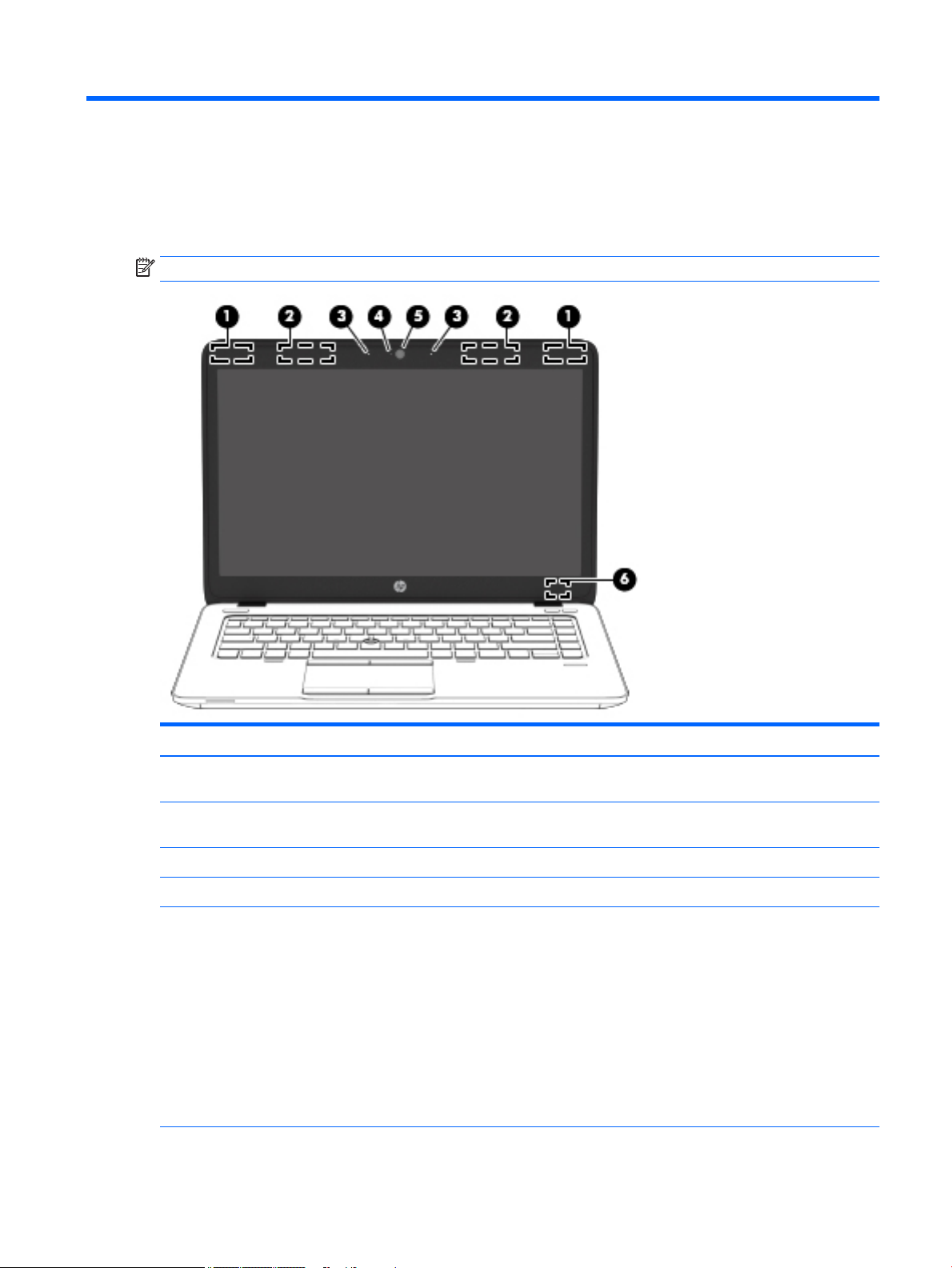
2 External component identication
Display
NOTE: Your computer may look slightly dierent from the illustration in this section.
Component Description
(1) WLAN antennas* Send and receive wireless signals to communicate with wireless local
area networks (WLAN).
(2) WWAN antennas* (select models only) Send and receive wireless signals to communicate with wireless wide
area networks (WWAN).
(3) Internal microphones Record sound.
(4) Webcam light On: The webcam is in use.
(5) Webcam Records video and captures photographs. Some models allow you to
video conference and chat online using streaming video.
To use the webcam:
Windows 7: Select Start > All Programs > Communication and Chat
> CyberLink YouCam.
Windows 8.1: Access HP Support Assistant. To access HP Support
Assistant, from the Start screen, select the HP Support Assistant
app.
Windows 10: Type camera in the taskbar search box, and then
select Camera.
Display 9
Page 20
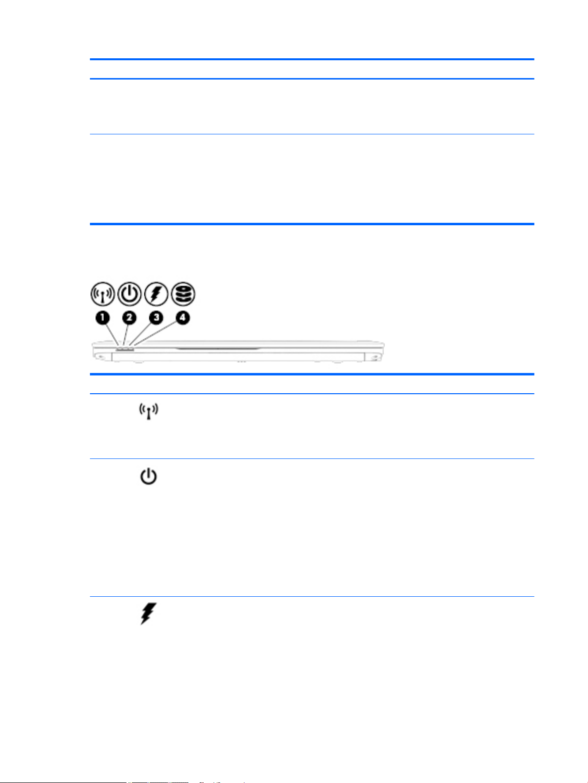
Front
Component Description
(6) Internal display switch Turns o the display or initiates Sleep if the display is closed while
the power is on.
NOTE: The display switch is not visible from the outside of the
computer.
*The antennas are not visible from the outside of the computer. For optimal transmission, keep the areas immediately around the
antennas free from obstructions. For wireless regulatory notices, see the section of the Regulatory, Safety, and Environmental Notices
that applies to your country or region. To access this guide:
Windows 7: Select Start > Help and Support > User Guides.
Windows 8.1: From the Start screen, type support, and then select the HP Support Assistant app.
Windows 10: Select Start, select All apps, select HP Help and Support, and then select HP Documentation.
Component Description
(1) Wireless light On: An integrated wireless device, such as a wireless local
area network (WLAN) device and/or a Bluetooth® device, is
on.
NOTE: On some models, the wireless light is amber when
all wireless devices are o.
(2) Power light
(3) AC adapter/Battery light
●
On: The computer is on.
●
Blinking: The computer is in the Sleep state, a powersaving state. The computer shuts o power to the
display and other unneeded components.
●
O: The computer is o or in Hibernation.
Hibernation is a power-saving state that uses the
least amount of power.
NOTE: For select models, the Intel® Rapid Start
Technology feature is enabled at the factory. Rapid Start
Technology allows your computer to resume quickly from
inactivity.
●
White: The computer is connected to external power
and the battery is charged from 90 to 99 percent.
●
Amber: The computer is connected to external power
and the battery is charged from 0 to 90 percent.
●
Blinking amber: A battery that is the only available
power source has reached a low battery level. When
the battery reaches a critical battery level, the
battery light begins blinking rapidly.
10 Chapter 2 External component identication
Page 21
Component Description
●
O: The battery is fully charged.
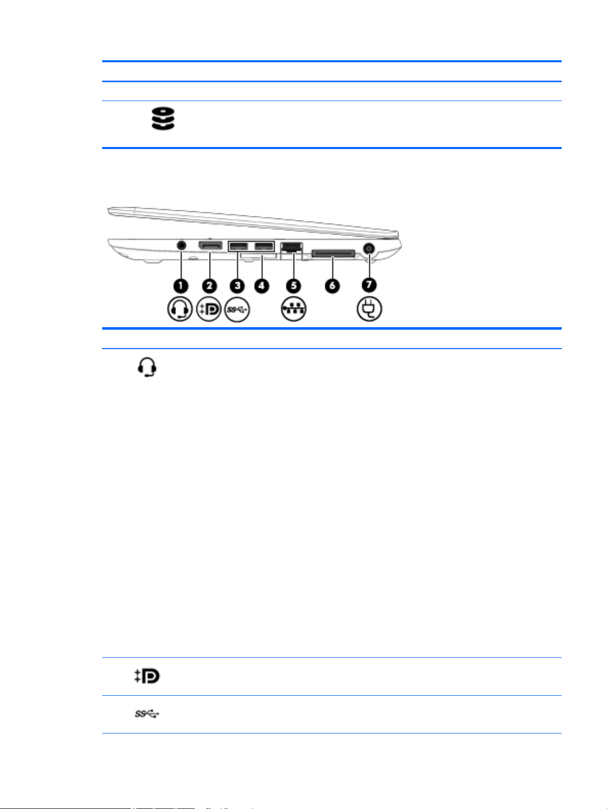
Right
(4) Hard drive light
Component Description
(1) Audio-out (headphone)/Audio-in
(microphone) jack
Connects optional powered stereo speakers, headphones, earbuds, or a
headset. Also connects an optional headset microphone. This jack does not
support optional microphone-only devices.
WARNING! To reduce the risk of personal injury, adjust the volume before
putting on headphones, earbuds, or a headset. For additional safety
information, see the Regulatory, Safety, and Environmental Notices.
To access this document:
Windows 7:
Select Start > Help and Support > User Guides.
Windows 8.1:
From the Start screen, type support, and then select the HP Support
Assistant app.
‒ or –
From the Windows desktop, click the question mark icon in the notication
area, at the far right of the taskbar.
Windows 10:
Select Start, select All apps, select HP Help and Support, and then select HP
Documentation.
NOTE: When a device is connected to the jack, the computer speakers are
disabled.
NOTE: Be sure that the device cable has a 4-conductor connector that
supports both audio-out (headphone) and audio-in (microphone).
●
Blinking white: The hard drive is being accessed.
●
Amber: HP 3D DriveGuard has temporarily parked the
hard drive.
(2) DisplayPort Connects an optional digital display device, such as a high-performance
monitor or projector.
(3) USB 3.0 ports Connect optional USB devices, such as a keyboard, mouse, external drive,
printer, scanner or USB hub.
Right 11
Page 22
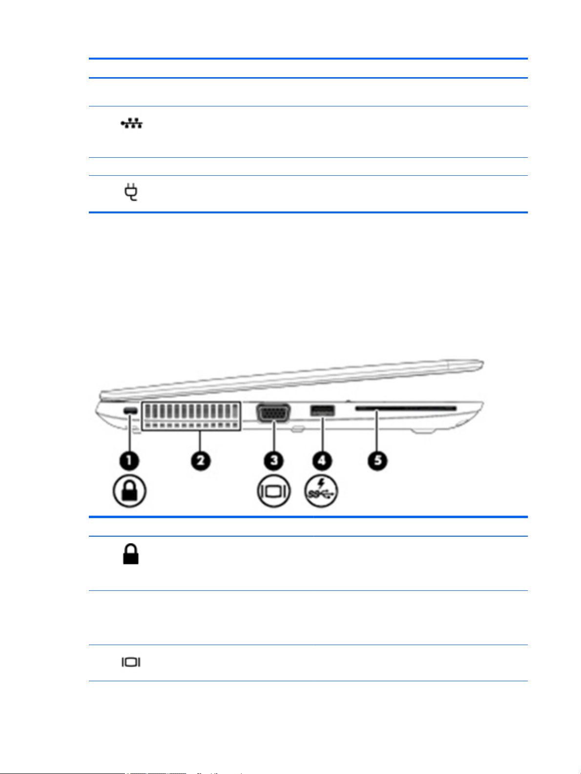
Left
Component Description
(4) Memory card reader Reads optional memory cards that store, manage, share, or access
information.
(5) RJ-45 (network) jack/lights Connects a network cable.
●
Green (left): The network is connected.
●
Amber (right): Activity is occurring on the network.
(6) Docking connector Connects an optional docking device.
(7) Power connector Connects an AC adapter.
Component Description
(1) Security cable slot Attaches an optional security cable to the computer.
(2) Vents Enable airow to cool internal components.
(3) External monitor port Connects an external VGA monitor or projector.
12 Chapter 2 External component identication
NOTE: The security cable is designed to act as a deterrent, but
it may not prevent the computer from being mishandled or
stolen.
NOTE: The computer fan starts up automatically to cool
internal components and prevent overheating. It is normal for
the internal fan to cycle on and o during routine operation.
Page 23
Top
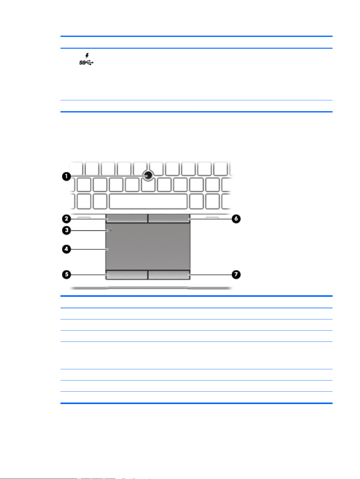
TouchPad
Component Description
(4) USB 3.0 charging (powered) port Connects an optional USB device, such as a keyboard, mouse,
external drive, printer, scanner or USB hub. Standard USB ports
will not charge all USB devices or will charge using a low current.
Some USB devices require power and require you to use a
powered port.
NOTE: USB charging ports can also charge select models of
cell phones and MP3 players, even when the computer is o.
(5) Smart card reader Supports optional smart cards.
Component Description
(1) Pointing stick Moves the pointer and selects or activates items on the screen.
(2) Left pointing stick button Functions like the left button on an external mouse.
(3) TouchPad on/o button Turns the TouchPad on and o.
(4) TouchPad zone Reads your nger gestures to move the pointer or activate
items on the screen.
NOTE: The TouchPad also supports edge-swipe gestures.
(5) Left TouchPad button Functions like the left button on an external mouse.
(6) Right pointing stick button Functions like the right button on an external mouse.
(7) Right TouchPad button Functions like the right button on an external mouse.
Top 13
Page 24
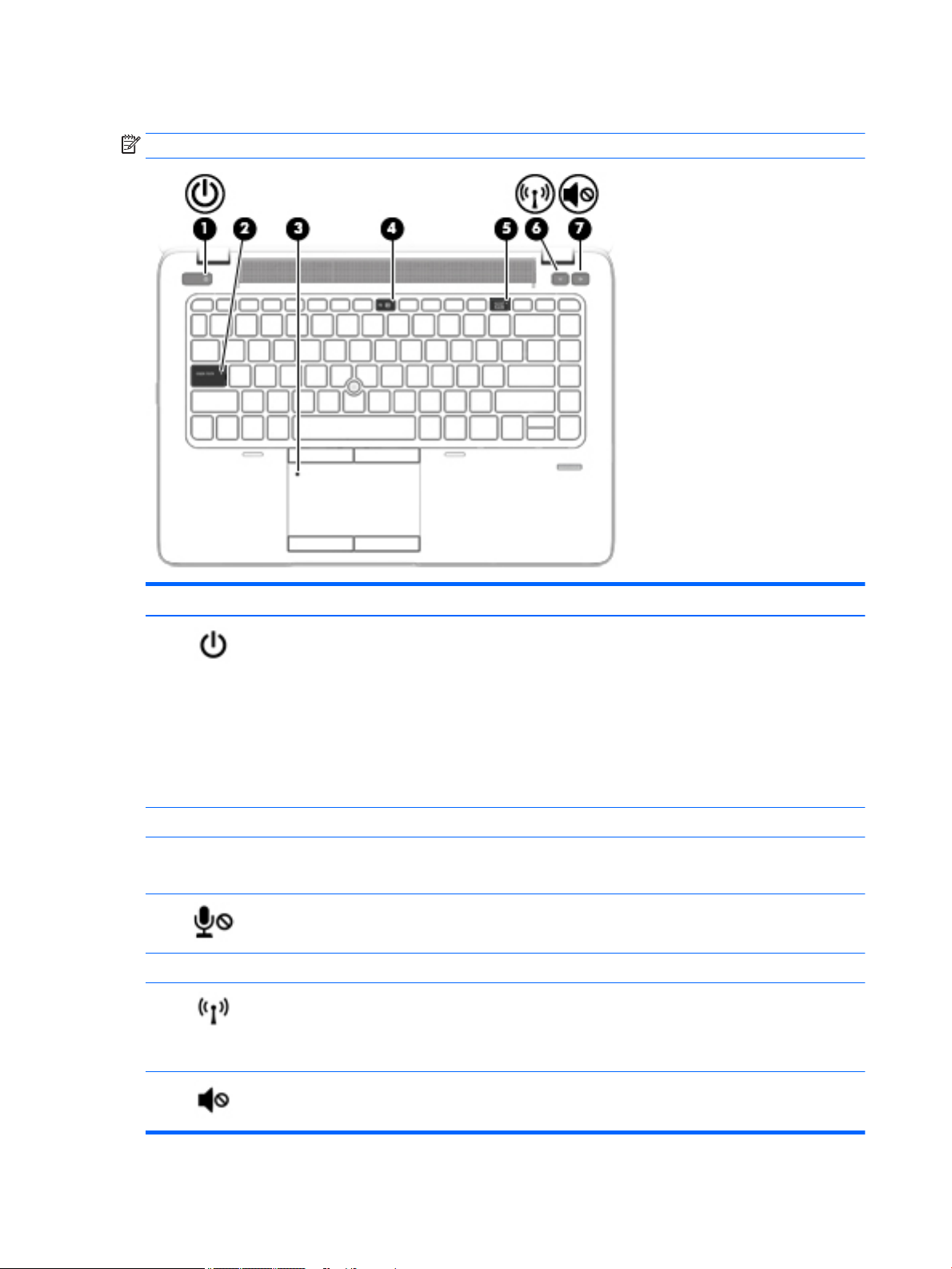
Lights
NOTE: Your computer may look slightly dierent from the illustration in this section.
Component Description
(1) Power light
(2) Caps lock light On: Caps lock is on, which switches the keys to all capital letters.
(3) TouchPad light
(4) Microphone mute light
(5) Num lock light On: Num lock is on.
(6) Wireless light On: An integrated wireless device, such as a wireless local area
●
On: The computer is on.
●
Blinking: The computer is in the Sleep state, a power-saving
state. The computer shuts o power to the display and
other unneeded components.
●
O: The computer is o or in Hibernation. Hibernation is a
power-saving state that uses the least amount of power.
NOTE: For select models, the Intel® Rapid Start Technology
feature is enabled at the factory. Rapid Start Technology allows
your computer to resume quickly from inactivity.
●
On: The TouchPad is o.
●
O: The TouchPad is on.
●
Amber: microphone sound is o.
●
O: microphone sound is on.
network (WLAN) device and/or a Bluetooth® device, is on.
NOTE: On some models, the wireless light is amber when all
wireless devices are o.
(7) Mute light
14 Chapter 2 External component identication
●
Amber: Computer sound is o.
●
O: Computer sound is on.
Page 25
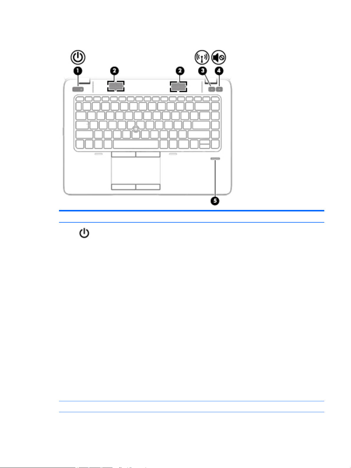
Buttons, speakers, and ngerprint reader (select models only)
Component Description
(1) Power button
●
When the computer is o, press the button to turn on the computer.
●
When the computer is on, press the button briey to initiate Sleep.
●
When the computer is in the Sleep state, press the button briey to exit Sleep.
●
When the computer is in Hibernation, press the button briey to exit
Hibernation.
CAUTION: Pressing and holding down the power button will result in the loss of
unsaved information.
If the computer has stopped responding and Windows shutdown procedures are
ineective, press and hold the power button for at least 5 seconds to turn o the
computer.
NOTE: For select models, the Intel® Rapid Start Technology feature is enabled at
the factory. Rapid Start Technology allows your computer to resume quickly from
inactivity.
To learn more about your power settings, see your power options:
Windows 7: Select Start > Control Panel > System and Security > Power Options.
Windows 8.1: From the Start screen, type power, select Power and sleep settings,
and then select Power and sleep from the list of applications.
Windows 10: Type power in the taskbar search box, and then select Power and
sleep settings.
– or –
Right-click the Start button, and then select Power Options.
(2) Speakers Produce sound.
Top 15
Page 26
Component Description
(3) Wireless button Turns the wireless feature on or o but does not establish a wireless connection.
(4) Volume mute button Mutes and restores speaker sound.
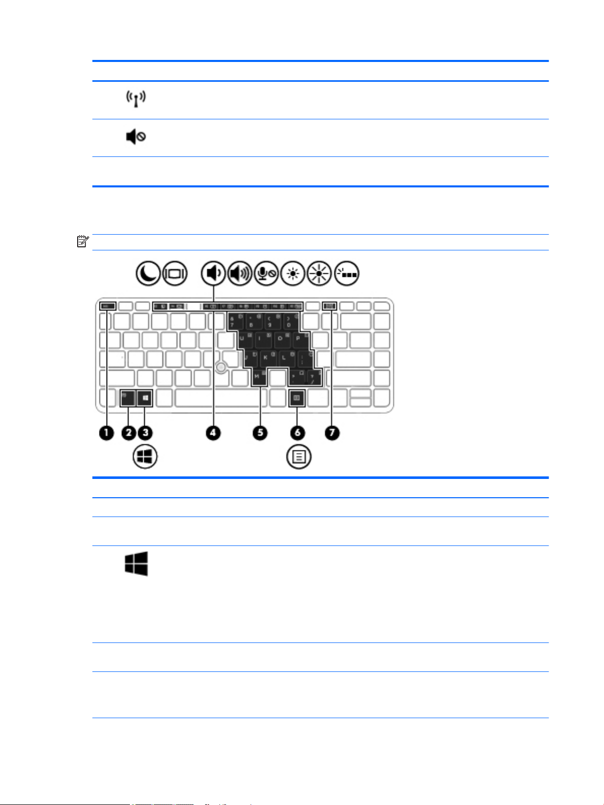
Keys
(5) Fingerprint reader (select
models only)
Allows a ngerprint logon to Windows, instead of a password logon.
NOTE: Your computer may look slightly dierent from the illustration in this section.
Component Description
(1) esc key Displays system information when pressed in combination with the fn key.
(2) fn key Executes frequently used system functions when pressed in combination with a
(3) Windows key Windows 7: Displays the Windows Start menu.
(4) Function keys Execute frequently used system functions when pressed in combination with the
(5) Embedded numeric keypad When the keypad is turned on, it can be used like an external numeric keypad.
16 Chapter 2 External component identication
function key or the esc key.
Windows 8.1: Returns you to the Start screen from an open app or the Windows
desktop.
NOTE: Pressing the Windows key again will return you to the previous screen.
Windows 10: Opens the Windows Start menu.
NOTE: Pressing the Windows key again will close the Start menu.
fn key.
Each key on the keypad performs the function indicated by the icon in the upperright corner of the key.
Page 27

Component Description
(6) Windows applications key Windows 7: Displays a shortcut menu for items beneath the cursor.
Windows 8.1: Displays options for a selected object.
Windows 10: Displays options for a selected object.
(7) num lk key Turns the embedded numeric keypad on and o when pressed in combination with
the fn key.
Alternates between the navigational and numeric functions on the embedded
numeric keypad.
Top 17
Page 28
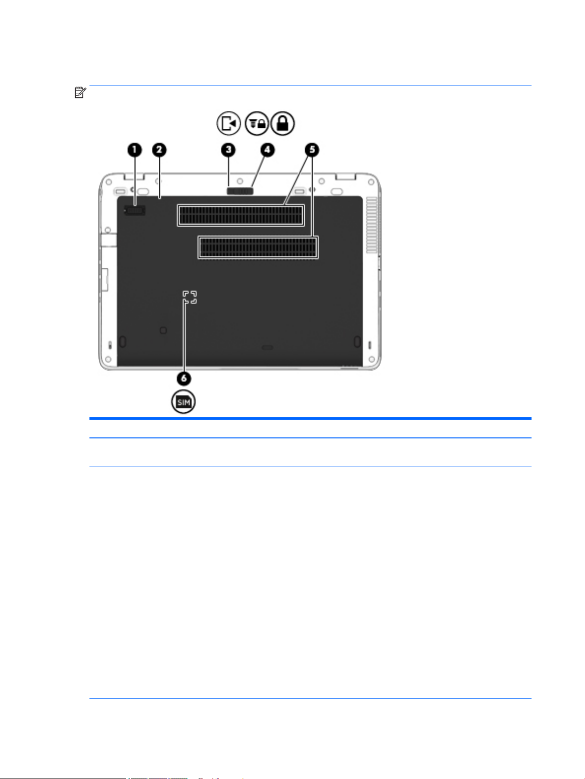
Bottom
NOTE: Your computer may look slightly dierent from the illustration in this section.
Component Description
(1) Accessory battery connector (select models
only)
(2) Service door Provides access to the hard drive bay, the wireless LAN
Connects an optional accessory battery.
(WLAN) module slot, the WWAN module slot, and the
memory module slots.
CAUTION: To prevent an unresponsive system, replace
the wireless module only with a wireless module
authorized for use in the computer by the governmental
agency that regulates wireless devices in your country or
region. If you replace the module and then receive a
warning message, remove the module to restore computer
functionality, and then contact support through HP
Support Assistant.
To access Help and Support in Windows 7, select Start >
Help and Support.
To access HP Support Assistant in Windows 8.1, from the
Start screen, select the HP Support Assistant app.
Windows 10: Type support in the taskbar search box,
and then select the HP Support Assistant app.
– or –
Click the question mark icon in the taskbar.
18 Chapter 2 External component identication
Page 29
Component Description
(3) Service door release latch Releases the service door.
(4) Service door release lock Locks the service door.
(5) Vents (2) Enable airow to cool internal components.
NOTE: The computer fan starts up automatically to cool
internal components and prevent overheating. It is normal
for the internal fan to cycle on and o during routine
operation.
(6) SIM slot (select models only) Supports a wireless subscriber identity module (SIM). The
SIM slot is located inside the battery bay.
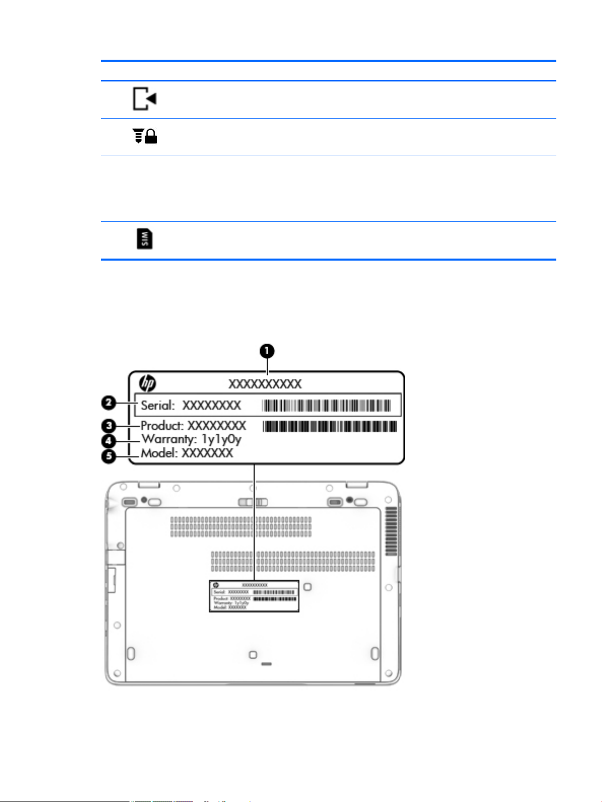
Locating the serial number, product number, and model number
The serial number, product number, and model number of your computer are located on the rear of the
computer. You may need the information when you travel internationally or when you contact support.
Locating the serial number, product number, and model number 19
Page 30
3 Illustrated parts catalog
NOTE: HP continually improves and changes product parts. For complete and current information on
supported parts for your computer, go to http://partsurfer.hp.com, select your country or region, and then
follow the on-screen instructions.
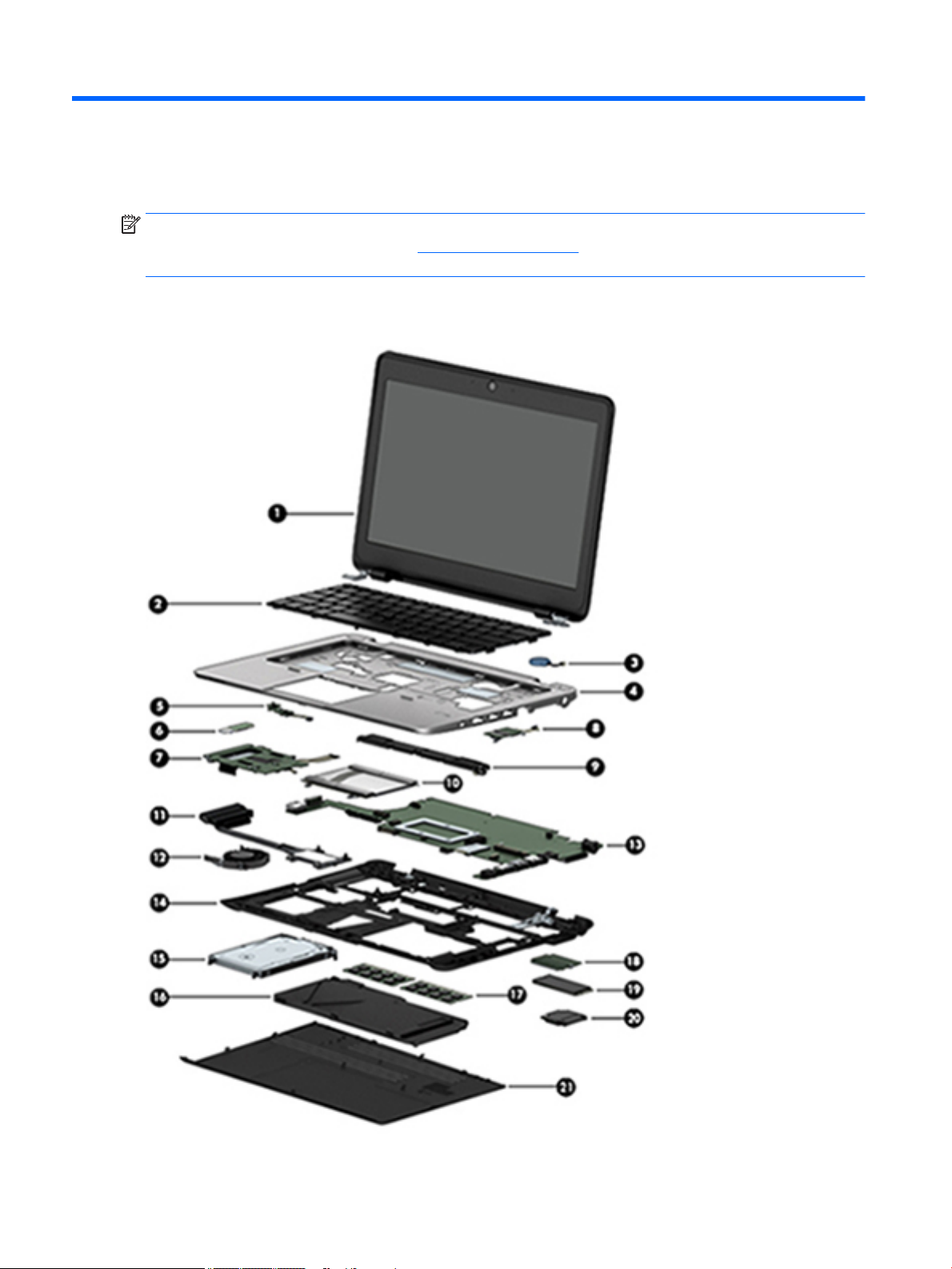
Computer major components
20 Chapter 3 Illustrated parts catalog
Page 31

Item Component Spare part number
(1) Display assembly: The TouchScreen display assembly is spared as a whole unit replacement.
12.5-in, AntiGlare, FHD, LED, UWVA, TouchScreen display assembly 781838-001
The non-TouchScreen display assembly is spared at the subcomponent level only. For more display assembly spare part
information, see Display assembly components on page 26.
(2) Keyboard with backlight (includes backlight cable and keyboard cable):
For use in models with a backlit keyboard:
For use in Belgium 776452-A41
For use in Brazil 776452-201
For use in Bulgaria 776452-261
For use in Canada 776452-DB1
For use in the Czech Republic and Slovakia 776452-FL1
For use in Denmark 776452-081
For use in France 776452-051
For use in Germany 776452-041
For use in Greece 776452-151
For use in Hungary 776452-211
For use in Iceland 776452-DD1
For use in India 776452-D61
For use in Israel 776452-BB1
For use in Italy 776452-061
For use in Japan 776452-291
For use in Latin America 776452-161
For use in the Netherlands 776452-B31
For use in Northwest Africa 776452-FP1
For use in Norway 776452-091
For use in Portugal 776452-131
For use in Romania 776452-271
For use in Russia 776452-251
For use in Saudi Arabia 776452-171
For use in Slovenia 776452-BA1
For use in South Korea 776452-AD1
For use in Spain 776452-071
For use in Sweden and Finland 776452-B71
For use in Switzerland 776452-BG1
Computer major components 21
Page 32

Item Component Spare part number
For use in Taiwan 776452-AB1
For use in Thailand 776452-281
For use in Turkey 776452-141
For use in the United Kingdom 776452-031
For use in the United States 776452-001
Keyboard without backlight (includes keyboard cable):
For use in models without a backlit keyboard:
For use in Belgium 776451-A41
For use in Brazil 776451-201
For use in Bulgaria 776451-261
For use in Canada 776451-DB1
For use in the Czech Republic and Slovakia 776451-FL1
For use in Denmark 776451-081
For use in France 776451-051
For use in Germany 776451-041
For use in Greece 776451-151
For use in Hungary 776451-211
For use in Iceland 776451-DD1
For use in India 776451-D61
For use in Israel 776451-BB1
For use in Italy 776451-061
For use in Japan 776451-291
For use in Latin America 776451-161
For use in the Netherlands 776451-B31
For use in Northwest Africa 776451-FP1
For use in Norway 776451-091
For use in Portugal 776451-131
For use in Romania 776451-271
For use in Russia 776451-251
For use in Saudi Arabia 776451-171
For use in Slovenia 776451-BA1
For use in South Korea 776451-AD1
For use in Spain 776451-071
For use in Sweden and Finland 776451-B71
22 Chapter 3 Illustrated parts catalog
Page 33

Item Component Spare part number
For use in Switzerland 776451-BG1
For use in Taiwan 776451-AB1
For use in Thailand 776451-281
For use in Turkey 776451-141
For use in the United Kingdom 776451-031
For use in the United States 776451-001
(3) RTC battery (includes cable and double-sided adhesive) 702853-001
(4) Top cover 783215-001
(5) Power button board (includes cable) 730552-001
(6) NFC module 781862-001
(7) Card reader board (includes cable) 781841-001
(8) Fingerprint reader board (includes bracket and cable) 730554-001
(9) Speaker assembly (includes left and right speakers and cables) 730555-001
(10) TouchPad (includes cable)
For use in models without NFC 781859-001
For use in models with NFC; includes NFC antenna 781860-001
(11) Heat sink (includes replacement thermal material): 730556-001
(12) Fan (includes cable): 730547-001
(13) System board, equipped with:
(includes a graphics subsystem with UMA memory and replacement thermal material)
All system boards use the following part numbers:
xxxxxx-001: Windows 7 or non-Windows operating systems
xxxxxx-501: Windows 8.1 Standard operating system
xxxxxx-601: Windows 8.1 or Windows 10 operating system
Intel Core i7-5600U processor 781858-xxx
Intel Core i7-5500U processor 781857-xxx
Intel Core i5-5300U processor 781856-xxx
Intel Core i5-5200U processor 781855-xxx
Intel Core i3-5010U processor 781854-xxx
(14) Base enclosure (includes RJ-45 cover, rubber feet, and service cover eject latch assembly): 765603-001
Rubber Kit (not illustrated, includes base enclosure rubber screw covers) 730550-001
(15) Hard drive (does not include hard drive bracket, hard drive connector adapter, or screws):
NOTE: The hard drive bracket, hard drive connector adapter, and screws are included in the Hard Drive Hardware Kit,
spare part number 730539-001.
1-TB, 5400-rpm, SATA, 7.0-mm hard drive 762990-001
Computer major components 23
Page 34

Item Component Spare part number
500-GB, 7200-rpm, SATA, 7.0-mm hard drive 703267-001
500-GB, 7200-rpm, SED, 7.0-mm hard drive 703268-001
500-GB, 5400-rpm, SATA, FIPS, 7.0-mm hard drive 730946-001
500-GB, 5400-rpm, SATA, 7.0-mm, hybrid SSD hard drive 732000-001
320-GB, 7200-rpm, SATA, 7.0-mm hard drive 778184-001
(16) Battery:
3-cell, 46-WHr, 4.15-AHr, Li-ion battery 717378-001
3-cell, 26-WHr, 2.50-AHr, Li-ion battery 717377-001
(17) Memory module (PCL3, 12800, 1600-MHz):
8 GB 693374-001
4 GB 691740-001
(18) WWAN module:
HP hs3110 HSPA+ Mobile Broadband Module 822828-001
HP lt4112 LTE/HPSA+ Mobile Broadband Module 790198-001
HP lt4211 LTE/EV-DO/HSPA+ Mobile Broadband Module 793116-001
(19) Solid-state drive:
NOTE: M.2 drive shown
512-GB, SATA-3, solid-state drive 781850-001
512-GB, SATA-3, solid-state drive, TLC 834733-001
256-GB, SATA-3, SED, Opal 2, solid-state drive 781849-001
256-GB, SATA-3, SATA-3, TLC, solid-state drive 798956-001
256-GB, M.2, PCIe, solid-state drive 781853-001
240-GB, SATA-3, solid-state drive 781847-001
180-GB, SATA-3, SED, Opal 2, solid-state drive 781846-001
180-GB, SATA-3, solid-state drive 781843-001
128-GB, SATA-3, TLC, solid-state drive 798955-001
128-GB, SATA-3, solid-state drive 781842-001
120-GB, SATA-3, M.2, solid-state drive 781852-001
32-GB, SATA-3, M.2, solid-state drive 781851-001
(20) WLAN module:
Intel Dual Band Wireless-AC 7265AN 802.11 a/b/g/n 2×2 WiFi + Bluetooth 4.0 WLAN module 756748-001
Intel Dual Band Wireless-N 7265 802.11 a/c 2×2 WiFi + Bluetooth 4.0 Combo Adapter 756749-001
Intel Dual Band Wireless-N 7265 802.11 a/c 2×2 WiFi + Bluetooth 4.0 Combo Adapter for use
in Indonesia
Intel Dual Band Wireless-AC 3160 802.11 a/b/g/n+a/c 2×2 WiFi Adapter 784644-001
24 Chapter 3 Illustrated parts catalog
783721-001
Page 35

Item Component Spare part number
(21) Service cover (includes rubber feet):
For use in 820 G2 models 781836-001
For use in 720 G2 models 790080-001
For use only on RCTO models 797517-001
Plastics Kit
Item Component Spare part number
Plastics Kit, includes: 730562-001
(1) Card reader bezel
(2) Display cable connector bracket
(3) Fingerprint reader cover
(4) RJ-45 cover
(5a) Service cover release latch actuator
(5b) Service cover release latch arm
Service cover release latch spring (not illustrated)
Plastics Kit 25
Page 36

Display assembly components
NOTE: The display assembly components listed in this section are for use only on computer models
equipped with a non-TouchScreen display assembly.
Item Component Spare part number
(1) Display bezel:
For use on 720 G2 models with an HD display panel 786930-001
For use on 720 G2 models with an FHD display panel 790381-001
For use on 820 G2 models with an HD display panel 730544-001
For use on 820 G2 models with an FHD display panel 781837-001
(2) Webcam/microphone module (includes double-sided adhesive): 781861-001
26 Chapter 3 Illustrated parts catalog
Page 37

Item Component Spare part number
Microphone module (includes double-sided adhesive) 730795-001
(3) Display panel:
12.5-in, AG, FHD, LED, UWVA display panel 781864-001
12.5-in, AG, HD, LED, SVA display panel 781863-001
(4) Display Hinge Kit (includes left and right display hinges):
For use only on computer models equipped with an FHD display 775895-001
For use only on computer models equipped with an HD display 730543-001
(5) Display Cable Kit (includes display panel cable and webcam/microphone module cable) 730537-001
Antenna Kit, includes:
(6) WLAN antenna cables and transceivers
(7) WWAN antenna cables and transceivers
For use only on computer models equipped with an HD display 781834-001
For use only on computer models equipped with an FHD display 781835-001
(8) Display enclosure:
For use only on computer models equipped with an FHD display 775893-001
For use only on computer models equipped with an HD display 730561-001
Display Panel Support Kit (not illustrated, includes display enclosure, WLAN antenna cables and transceivers, and WWAN
antenna cables and transceivers):
For use only on computer models equipped with an HD display 781839-001
For use only on computer models equipped with an FHD display 781840-001
Display assembly components 27
Page 38

Mass storage devices
Item Component Spare part number
(1) Hard drive (does not include hard drive bracket, hard drive connector adapter, or screws):
NOTE: The hard drive bracket, hard drive connector adapter, and screws are included in the Hard Drive Hardware Kit,
spare part number 730539-001.
1-TB, 5400-rpm, SATA, 7.0-mm hard drive 762990-001
500-GB, 7200-rpm, SATA, 7.0-mm hard drive 703267-001
500-GB, 7200-rpm, SED, 7.0-mm hard drive 703268-001
500-GB, 5400-rpm, SATA, FIPS, 7.0-mm hard drive 730946-001
500-GB, 5400-rpm, SATA, 7.0-mm, hybrid SSD hard drive 732000-001
320-GB, 7200-rpm, SATA, 7.0-mm hard drive 778184-001
Solid-state drive, 2.5-inch (does not include hard drive bracket, hard drive connector adapter, or screws):
NOTE: The hard drive bracket, hard drive connector adapter, and screws are included in the Hard Drive Hardware Kit.
512-GB, SATA-3, solid-state drive 781850-001
512-GB, SATA-3, solid-state drive, TLC 834733-001
256-GB, SATA-3, SED, Opal 2, solid-state drive 781849-001
256-GB, SATA-3, TLC, solid-state drive 798956-001
256-GB, M.2, PCIe, solid-state drive 781853-001
240-GB, SATA-3, solid-state drive 781847-001
180-GB, SATA-3, SED, Opal 2, solid-state drive 781846-001
180-GB, SATA-3, solid-state drive 781843-001
28 Chapter 3 Illustrated parts catalog
Page 39

Item Component Spare part number
128-GB, SATA-3, TLC, solid-state drive 798955-001
128-GB, SATA-3, solid-state drive 781842-001
M.2 solid-state drive (not illustrated)
120-GB, SATA-3, M.2 solid-state drive 781852-001
32-GB, SATA-3, M.2, solid-state drive 781851-001
Hard drive hardware kit (does not include hard drive bracket, hard drive connector adapter,
or screws):
NOTE: The hard drive bracket, hard drive connector adapter, and screws are included in
the Hard Drive Hardware Kit.
(2a) Hard drive bracket
(2b) Hard drive connector adapter
Hard drive screws (not illustrated)
Miscellaneous parts
Component Spare part number
AC adapter:
65-W HP Smart adapter (EM, RC/V, 3-wire, 4.5-mm) 693710-001
65-W HP Smart adapter (non-PFC, 3-wire, 4.5-mm) 693711-001
45-W HP Smart adapter (non-PFC, RC, 7.4-mm) 744893-001
45-W HP Smart adapter (non-PFC, RC, 3-wire, 4.5-mm) 721092-001
45-W HP Smart adapter (non-PFC, RC, 2-wire, 4.5-mm) 742437-001
730539-001
65-W, 3-pin to standard connector (converts 3-pin Smart power connector to standard/legacy power
connector)
Smart AC adapter dongle, 7.4mm 734734-001
HP DisplayPort-to-HDMI 1.4 adapter 749288-001
Carrying case:
HP Essential top-load carrying case 679921-001
HP business top-load carrying case 718550-001
HP 2013 UltraSlim Docking Station 732252-001
HP Mobile Connect SIM module 714749-001
Lock:
HP docking station cable lock 575921-001
HP ultraslim keyed cable lock 703372-001
Mouse:
HP comfort-grip wireless mouse 691922-001
414135-001
Miscellaneous parts 29
Page 40

Component Spare part number
HP USB laser mouse 674318-001
HP USB travel mouse 757770-001
Power cord (3-pin, black, 1.83-m):
For use in Argentina 490371-D01
For use in Australia 490371-011
For use in Brazil 490371-202
For use in Denmark 490371-081
For use in Europe 490371-021
For use in India 490371-D61
For use in Israel 490371-BB1
For use in Italy 490371-061
For use in Japan 490371-291
For use in North America 490371-001
For use in the People's Republic of China 490371-AA1
For use in South Africa 490371-AR1
For use in South Korea 490371-AD1
For use in Switzerland 490371-111
For use in Taiwan 490371-AB1
For use in Thailand 490371-201
For use in the United Kingdom and Singapore 490371-031
Power cord (3-pin, black, 1.00-m):
For use in Argentina 755530-D01
For use in Australia 755530-011
For use in Brazil 755530-202
For use in Denmark 755530-081
For use in Europe 755530-021
For use in India 755530-D61
For use in Israel 755530-BB1
For use in Italy 755530-061
For use in Japan 755530-291
For use in North America 755530-001
For use in the People's Republic of China 755530-AA1
For use in South Africa 755530-AR1
For use in South Korea 755530-AD1
30 Chapter 3 Illustrated parts catalog
Page 41

Component Spare part number
For use in Switzerland 755530-111
For use in Taiwan 755530-AB1
For use in Thailand 755530-201
For use in the United Kingdom and Singapore 755530-031
Power cord for use in Japan (2-pin, black, 1.00-m): 762689-291
Screw Kit 730553-001
Mylar tape 828770-001
Pointing stick covers, black (20 pieces) 804089-001
Miscellaneous parts 31
Page 42

4 Removal and replacement preliminary
requirements
Tools required
You will need the following tools to complete the removal and replacement procedures:
●
Flat-bladed screw driver
●
Magnetic screw driver
●
Phillips P0 screw driver
Service considerations
The following sections include some of the considerations that you must keep in mind during disassembly
and assembly procedures.
NOTE: As you remove each subassembly from the computer, place the subassembly (and all accompanying
screws) away from the work area to prevent damage.
Plastic parts
CAUTION: Using excessive force during disassembly and reassembly can damage plastic parts. Use care
when handling the plastic parts. Apply pressure only at the points designated in the
maintenance instructions.
32 Chapter 4 Removal and replacement preliminary requirements
Page 43

Cables and connectors
CAUTION: When servicing the computer, be sure that cables are placed in their proper locations during the
reassembly process. Improper cable placement can damage the computer.
Cables must be handled with extreme care to avoid damage. Apply only the tension required to unseat or seat
the cables during removal and insertion. Handle cables by the connector whenever possible. In all cases, avoid
bending, twisting, or tearing cables. Be sure that cables are routed in such a way that they cannot be caught
or snagged by parts being removed or replaced. Handle ex cables with extreme care; these cables tear
easily.
Drive handling
CAUTION: Drives are fragile components that must be handled with care. To prevent damage to the
computer, damage to a drive, or loss of information, observe these precautions:
Before removing or inserting a hard drive, shut down the computer. If you are unsure whether the computer is
o or in Hibernation, turn the computer on, and then shut it down through the operating system.
Before handling a drive, be sure that you are discharged of static electricity. While handling a drive, avoid
touching the connector.
Before removing a diskette drive or optical drive, be sure that a diskette or disc is not in the drive and be sure
that the optical drive tray is closed.
Handle drives on surfaces covered with at least one inch of shock-proof foam.
Avoid dropping drives from any height onto any surface.
After removing a hard drive, an optical drive, or a diskette drive, place it in a static-proof bag.
Avoid exposing an internal hard drive to products that have magnetic elds, such as monitors or speakers.
Avoid exposing a drive to temperature extremes or liquids.
If a drive must be mailed, place the drive in a bubble pack mailer or other suitable form of protective
packaging and label the package “FRAGILE.”
Grounding guidelines
Electrostatic discharge damage
Electronic components are sensitive to electrostatic discharge (ESD). Circuitry design and structure determine
the degree of sensitivity. Networks built into many integrated circuits provide some protection, but in many
cases, ESD contains enough power to alter device parameters or melt silicon junctions.
A discharge of static electricity from a nger or other conductor can destroy static-sensitive devices or
microcircuitry. Even if the spark is neither felt nor heard, damage may have occurred.
An electronic device exposed to ESD may not be aected at all and can work perfectly throughout a normal
cycle. Or the device may function normally for a while, then degrade in the internal layers, reducing its life
expectancy.
Grounding guidelines 33
Page 44

CAUTION: To prevent damage to the computer when you are removing or installing internal components,
observe these precautions:
Keep components in their electrostatic-safe containers until you are ready to install them.
Before touching an electronic component, discharge static electricity by using the guidelines described in this
section.
Avoid touching pins, leads, and circuitry. Handle electronic components as little as possible.
If you remove a component, place it in an electrostatic-safe container.
The following table shows how humidity aects the electrostatic voltage levels generated by
dierent activities.
CAUTION: A product can be degraded by as little as 700 V.
Typical electrostatic voltage levels
Relative humidity
Event 10% 40% 55%
Walking across carpet 35,000 V 15,000 V 7,500 V
Walking across vinyl oor 12,000 V 5,000 V 3,000 V
Motions of bench worker 6,000 V 800 V 400 V
Removing DIPS from plastic tube 2,000 V 700 V 400 V
Removing DIPS from vinyl tray 11,500 V 4,000 V 2,000 V
Removing DIPS from Styrofoam 14,500 V 5,000 V 3,500 V
Removing bubble pack from PCB 26,500 V 20,000 V 7,000 V
Packing PCBs in foam-lined box 21,000 V 11,000 V 5,000 V
34 Chapter 4 Removal and replacement preliminary requirements
Page 45

Packaging and transporting guidelines
Follow these grounding guidelines when packaging and transporting equipment:
●
To avoid hand contact, transport products in static-safe tubes, bags, or boxes.
●
Protect ESD-sensitive parts and assemblies with conductive or approved containers or packaging.
●
Keep ESD-sensitive parts in their containers until the parts arrive at static-free workstations.
●
Place items on a grounded surface before removing items from their containers.
●
Always be properly grounded when touching a component or assembly.
●
Store reusable ESD-sensitive parts from assemblies in protective packaging or nonconductive foam.
●
Use transporters and conveyors made of antistatic belts and roller bushings. Be sure that mechanized
equipment used for moving materials is wired to ground and that proper materials are selected to avoid
static charging. When grounding is not possible, use an ionizer to dissipate electric charges.
Workstation guidelines
Follow these grounding workstation guidelines:
●
Cover the workstation with approved static-shielding material.
●
Use a wrist strap connected to a properly grounded work surface and use properly grounded tools and
equipment.
●
Use conductive eld service tools, such as cutters, screw drivers, and vacuums.
●
When xtures must directly contact dissipative surfaces, use xtures made only of static-safe materials.
●
Keep the work area free of nonconductive materials, such as ordinary plastic assembly aids
and Styrofoam.
●
Handle ESD-sensitive components, parts, and assemblies by the case or PCM laminate. Handle these
items only at static-free workstations.
●
Avoid contact with pins, leads, or circuitry.
●
Turn o power and input signals before inserting or removing connectors or test equipment.
Grounding guidelines 35
Page 46

Equipment guidelines
Grounding equipment must include either a wrist strap or a foot strap at a grounded workstation.
●
When seated, wear a wrist strap connected to a grounded system. Wrist straps are exible straps with a
minimum of one megohm ±10% resistance in the ground cords. To provide proper ground, wear a strap
snugly against the skin at all times. On grounded mats with banana-plug connectors, use alligator clips
to connect a wrist strap.
●
When standing, use foot straps and a grounded oor mat. Foot straps (heel, toe, or boot straps) can be
used at standing workstations and are compatible with most types of shoes or boots. On conductive
oors or dissipative oor mats, use foot straps on both feet with a minimum of one megohm resistance
between the operator and ground. To be
The following grounding equipment is recommended to prevent electrostatic damage:
●
Antistatic tape
●
Antistatic smocks, aprons, and sleeve protectors
●
Conductive bins and other assembly or soldering aids
●
Nonconductive foam
●
Conductive computerop workstations with ground cords of one megohm resistance
●
Static-dissipative tables or oor mats with hard ties to the ground
●
Field service kits
eective, the conductive must be worn in contact with the skin.
●
Static awareness labels
●
Material-handling packages
●
Nonconductive plastic bags, tubes, or boxes
●
Metal tote boxes
●
Electrostatic voltage levels and protective materials
The following table lists the shielding protection provided by antistatic bags and oor mats.
Material Use Voltage protection level
Antistatic plastics Bags 1,500 V
Carbon-loaded plastic Floor mats 7,500 V
Metallized laminate Floor mats 5,000 V
36 Chapter 4 Removal and replacement preliminary requirements
Page 47

5 Removal and replacement procedures for
Customer Self-Repair parts
NOTE: The Customer Self-Repair program is not available in all locations. Installing a part not supported by
the Customer Self-Repair program may void your warranty. Check your warranty to determine if Customer
Self-Repair is supported in your location.
NOTE: HP continually improves and changes product parts. For complete and current information on
supported parts for your computer, go to http://partsurfer.hp.com, select your country or region, and then
follow the on-screen instructions.
Component replacement procedures
This chapter provides removal and replacement procedures for Authorized Service Provider only parts.
There are as many as 15 screws that must be removed, replaced, and/or loosened when servicing the
computer. Make special note of each screw size and location during removal and replacement.
Service cover
NOTE: The service cover spare part kit includes rubber feet.
Description Spare part number
Service cover for use in 820 G2 models 781836-001
Service cover for use in 720 G2 models 790080-001
Service cover for use only on RCTO models 797517-001
Before removing the disassembling the computer, follow these steps:
1. Turn o the computer. If you are unsure whether the computer is o or in Hibernation, turn the
computer on, and then shut it down through the operating system.
2. Disconnect the power from the computer by unplugging the power cord from the computer.
3. Disconnect all external devices from the computer.
Remove the service cover:
1. Turn the computer upside down, with the rear toward you.
2. Slide the service cover release latch (1) to gain access to the service cover security screw.
3. Remove the Phillips PM2.0×4.5 security screw (2) (if present).
NOTE: The service cover includes a threaded receptacle for storing the security screw.
4. Slide the service cover release latch a second time (3) to release the service cover.
5. Release the service cover (4) by sliding it forward.
Component replacement procedures 37
Page 48

6. Remove the service cover (5).
Reverse this procedure to install the service cover.
38 Chapter 5 Removal and replacement procedures for Customer Self-Repair parts
Page 49

Battery
Description Spare part number
3-cell, 46-WHr, 4.15-AHr, Li-ion battery 717378-001
3-cell, 26-WHr, 2.50-AHr, Li-ion battery 717377-001
Before removing the battery, follow these steps:
1. Turn o the computer. If you are unsure whether the computer is o or in Hibernation, turn the
computer on, and then shut it down through the operating system.
2. Disconnect the power from the computer by unplugging the power cord from the computer.
3. Disconnect all external devices from the computer.
4. Remove the service cover (see Service cover on page 37).
WARNING! To reduce potential safety issues, use only the battery provided with the computer, a
replacement battery provided by HP, or a compatible battery purchased from HP.
CAUTION: Removing a battery that is the sole power source for the computer can cause loss of information.
To prevent loss of information, save your work or shut down the computer through Windows before removing
the battery.
Remove the battery:
1. Slide the battery lock latches (1) to unlock the battery.
Component replacement procedures 39
Page 50

2. Use the release tab (2) to lift the rear edge of the battery (3) until the battery rests at an angle.
3. Remove the battery.
Reverse this procedure to install the battery.
40 Chapter 5 Removal and replacement procedures for Customer Self-Repair parts
Page 51

Hard drive/solid-state drive
NOTE: Hard drive or solid-state drive spare part kits do not include the hard drive bracket, hard drive
connector adapter, or screws. The hard drive bracket, hard drive connector adapter, and screws are included
in the Hard Drive Hardware Kit, spare part number 730539-001.
Description Spare part number
Hard drive (does not include hard drive bracket, hard drive connector adapter, or screws):
NOTE: The hard drive bracket, hard drive connector adapter, and screws are included in the Hard Drive Hardware Kit, spare part
number 730539-001.
1-TB, 5400-rpm, SATA, 7.0-mm hard drive 762990-001
500-GB, 7200-rpm, SATA, 7.0-mm hard drive 703267-001
500-GB, 7200-rpm, SED, 7.0-mm hard drive 703268-001
500-GB, 5400-rpm, SATA, FIPS, 7.0-mm hard drive 730946-001
500-GB, 5400-rpm, SATA, 7.0-mm, hybrid SSD hard drive 732000-001
320-GB, 7200-rpm, SATA, 7.0-mm hard drive 778184-001
Solid-state drive, 2.5-inch (does not include hard drive bracket, hard drive connector adapter, or screws):
NOTE: The hard drive bracket, hard drive connector adapter, and screws are included in the Hard Drive Hardware Kit.
512-GB, SATA-3, solid-state drive 781850-001
512-GB, SATA-3, solid-state drive, TLC 834733-001
256-GB, SATA-3, SED, Opal 2, solid-state drive 781849-001
256-GB, SATA-3, TLC, solid-state drive 798956-001
256-GB, M.2, PCIe, solid-state drive 781853-001
240-GB, SATA-3, solid-state drive 781847-001
180-GB, SATA-3, SED, Opal 2, solid-state drive 781846-001
180-GB, SATA-3, solid-state drive 781843-001
128-GB, SATA-3, TLC, solid-state drive 798955-001
128-GB, SATA-3, solid-state drive 781842-001
Before removing the battery, follow these steps:
1. Turn o the computer. If you are unsure whether the computer is o or in Hibernation, turn the
computer on, and then shut it down through the operating system.
2. Disconnect the power from the computer by unplugging the power cord from the computer.
3. Disconnect all external devices from the computer.
4. Remove the service cover (see Service cover on page 37).
5. Remove the battery (see Battery on page 39).
Remove the hard drive:
1. Loosen the four Phillips captive screws (1) that secure the hard drive to the computer.
Component replacement procedures 41
Page 52

2. Use the release tab (2) to remove the hard drive.
3. If it is necessary to disassemble the hard drive, perform the following steps:
a. Position the hard drive with the rear toward you.
b. Remove the four Phillips PM2.75×3.5 screws (1) that secure the hard drive bracket to the hard
drive.
c. Remove the hard drive bracket (2) from the hard drive.
42 Chapter 5 Removal and replacement procedures for Customer Self-Repair parts
Page 53

d. Remove the hard drive connector adapter (3) from the hard drive.
The hard drive bracket, hard drive connector adapter, and screws are available in the Hard Drive
Hardware Kit, spare part number 730539-001.
Reverse this procedure to reassemble and install the hard drive.
Component replacement procedures 43
Page 54

WWAN module
Description Spare part number
HP hs3110 HSPA+ Mobile Broadband Module 822828-001
HP lt4112 LTE/HPSA+ Mobile Broadband Module 790198-001
HP lt4111 LTE/EV-DO/HSPA+ Mobile Broadband Module 793116-001
Before removing the WWAN module, follow these steps:
1. Turn o the computer. If you are unsure whether the computer is o or in Hibernation, turn the
computer on, and then shut it down through the operating system.
2. Disconnect the power from the computer by unplugging the power cord from the computer.
3. Disconnect all external devices from the computer.
4. Remove the service cover (see Service cover on page 37).
5. Remove the battery (see Battery on page 39).
Remove the WWAN module:
1. Disconnect the WWAN antenna cables (1) from the terminals on the WWAN module.
NOTE: The WWAN antenna cable labeled “5” connects to the WWAN module “Main” terminal labeled
“5”. The WWAN antenna cable labeled “6” connects to the WWAN module “Aux/GPS” terminal labeled
“6”.
2. Remove the Phillips PM2.0×2.5 screw (2) that secures the WWAN module to the system board. (The
WWAN module tilts up.)
3. Remove the WWAN module (3) by pulling the module away from the slot at an angle.
NOTE: If the WWAN antenna cables are not connected to the terminals on the WWAN module, protective
sleeves should be installed on the antenna connectors, as shown in the following illustration.
44 Chapter 5 Removal and replacement procedures for Customer Self-Repair parts
Page 55

Reverse this procedure to install the WWAN module.
Component replacement procedures 45
Page 56

M.2 solid-state drive
Description Spare part number
120-GB, SATA-3, M.2, solid-state drive 781852-001
32-GB, SATA-3, M.2, solid-state drive 781851-001
Before removing the solid-state drive, follow these steps:
1. Turn o the computer. If you are unsure whether the computer is o or in Hibernation, turn the
computer on, and then shut it down through the operating system.
2. Disconnect the power from the computer by unplugging the power cord from the computer.
3. Disconnect all external devices from the computer.
4. Remove the service cover (see Service cover on page 37).
5. Remove the battery (see Battery on page 39).
Remove the solid-state drive:
1. Remove the Phillips PM2.0×2.5 screw (1) that secures the solid-state drive to the system board. (The
solid-state drive tilts up.)
2. Remove the solid-state drive (2) by pulling the drive away from the slot at an angle.
Reverse this procedure to install the solid-state drive.
46 Chapter 5 Removal and replacement procedures for Customer Self-Repair parts
Page 57

WLAN module
Description Spare part number
Intel Dual Band Wireless-AC 7265AN 802.11 a/b/g/n 2×2 WiFi + Bluetooth 4.0 WLAN module 756748-001
Intel Dual Band Wireless-N 7265 802.11 a/c 2×2 WiFi + Bluetooth 4.0 Combo Adapter 756749-001
Intel Dual Band Wireless-N 7265 802.11 a/c 2×2 WiFi + Bluetooth 4.0 Combo Adapter for use in Indonesia 783721-001
Intel Dual Band Wireless-AC 3160 802.11 a/b/g/n+a/c 2×2 WiFi Adapter 784644-001
Before removing the WLAN module, follow these steps:
1. Turn o the computer. If you are unsure whether the computer is o or in Hibernation, turn the
computer on, and then shut it down through the operating system.
2. Disconnect the power from the computer by unplugging the power cord from the computer.
3. Disconnect all external devices from the computer.
4. Remove the service cover (see Service cover on page 37).
5. Remove the battery (see Battery on page 39).
Remove the WLAN module:
1. Disconnect the WLAN antenna cables (1) from the terminals on the WLAN module.
NOTE: The WLAN antenna cable labeled “1” connects to the WLAN module “Main” terminal labeled “1”.
The WLAN antenna cable labeled “2” connects to the WLAN module “Aux” terminal labeled “2”.
2. Remove the Phillips PM2.0×2.0 screw (2) that secures the WLAN module to the system board. (The
WLAN module tilts up.)
3. Remove the WLAN module (3) by pulling the module away from the slot at an angle.
NOTE: If the WLAN antenna cables are not connected to the terminals on the WLAN module, protective
sleeves should be installed on the antenna connectors, as shown in the following illustration.
Component replacement procedures 47
Page 58

Reverse this procedure to install the WLAN module.
48 Chapter 5 Removal and replacement procedures for Customer Self-Repair parts
Page 59

Memory module
Description Spare part number
8 GB (PCL3, 12800, 1600-MHz) 693374-001
4 GB (PCL3, 12800, 1600-MHz) 691740-001
Before removing the memory module, follow these steps:
1. Turn o the computer. If you are unsure whether the computer is o or in Hibernation, turn the
computer on, and then shut it down through the operating system.
2. Disconnect the power from the computer by unplugging the power cord from the computer.
3. Disconnect all external devices from the computer.
4. Remove the service cover (see Service cover on page 37).
5. Remove the battery (see Battery on page 39).
Remove the memory module:
1. Spread the retaining tabs (1) on each side of the memory module slot to release the memory module.
(The memory module tilts up.)
2. Remove the memory module (2) by pulling the module away from the slot at an angle.
Reverse this procedure to install a memory module.
Component replacement procedures 49
Page 60

Keyboard
For use in country or region Spare part number For use in country or region Spare part number
Keyboard with backlight (includes backlight cable and keyboard cable):
For use in Belgium 776452-A41 For use in Northwest Africa 776452-FP1
For use in Brazil 776452-201 For use in Norway 776452-091
For use in Bulgaria 776452-261 For use in Portugal 776452-131
For use in Canada 776452-DB1 For use in Romania 776452-271
For use in the Czech Republic
and Slovakia
For use in Denmark 776452-081 For use in Saudi Arabia 776452-171
For use in France 776452-051 For use in Slovenia 776452-BA1
For use in Germany 776452-041 For use in South Korea 776452-AD1
For use in Greece 776452-151 For use in Spain 776452-071
For use in Hungary 776452-211 For use in Sweden and Finland 776452-B71
For use in Iceland 776452-DD1 For use in Switzerland 776452-BG1
For use in India 776452-D61 For use in Taiwan 776452-AB1
For use in Israel 776452-BB1 For use in Thailand 776452-281
For use in Italy 776452-061 For use in Turkey 776452-141
For use in Japan 776452-291 For use in the United Kingdom 776452-031
For use in Latin America 776452-161 For use in the United States 776452-001
For use in the Netherlands 776452-B31
For use in Belgium 776451-A41 For use in Northwest Africa 776451-FP1
For use in Brazil 776451-201 For use in Norway 776451-091
776452-FL1 For use in the Russia 776452-251
Keyboard without backlight (includes keyboard cable):
For use in Bulgaria 776451-261 For use in Portugal 776451-131
For use in Canada 776451-DB1 For use in Romania 776451-271
For use in the Czech Republic
and Slovakia
For use in Denmark 776451-081 For use in Saudi Arabia 776451-171
For use in France 776451-051 For use in Slovenia 776451-BA1
For use in Germany 776451-041 For use in South Korea 776451-AD1
For use in Greece 776451-151 For use in Spain 776451-071
For use in Hungary 776451-211 For use in Sweden and Finland 776451-B71
For use in Iceland 776451-DD1 For use in Switzerland 776451-BG1
For use in India 776451-D61 For use in Taiwan 776451-AB1
For use in Israel 776451-BB1 For use in Thailand 776451-281
776451-FL1 For use in the Russia 776451-251
50 Chapter 5 Removal and replacement procedures for Customer Self-Repair parts
Page 61

For use in country or region Spare part number For use in country or region Spare part number
For use in Italy 776451-061 For use in Turkey 776451-141
For use in Japan 776451-291 For use in the United Kingdom 776451-031
For use in Latin America 776451-161 For use in the United States 776451-001
For use in the Netherlands 776451-B31
Before removing the keyboard, follow these steps:
1. Turn o the computer. If you are unsure whether the computer is o or in Hibernation, turn the
computer on, and then shut it down through the operating system.
2. Disconnect the power from the computer by unplugging the power cord from the computer.
3. Disconnect all external devices from the computer.
4. Remove the service cover (see Service cover on page 37).
5. Remove the battery (see Battery on page 39).
Remove the keyboard:
1. Loosen the two captive screws that secure the keyboard to the computer.
2. Partially open the computer.
3. Rest and secure the computer on its left side.
Component replacement procedures 51
Page 62

4. Insert a thin, plastic tool into the keyboard release hole next to the fan, and then press on the back of
the keyboard until the keyboard disengages from the computer.
5. Open the computer as far as it will open.
6. Lift the rear edge of the keyboard (1) until it rests at an angle.
7. Slide the keyboard (2) toward the display until the tabs on the front edge of the keyboard disengage
from the top cover.
52 Chapter 5 Removal and replacement procedures for Customer Self-Repair parts
Page 63

8. Swing the rear edge of the keyboard (3) up and forward until it rests upside down on the palm rest.
NOTE: Step 9 applies only to computer models equipped with a keyboard with backlight.
9. Release the zero insertion force (ZIF) connector (1) to which the backlight cable is attached, and then
disconnect the backlight cable
10. Release the ZIF connector (3) to which the keyboard cable is attached, and then disconnect the keyboard
cable (4) from the system board.
(2) from the system board.
11. Release the ZIF connector (5) to which the pointing stick cable is attached, and then disconnect the
pointing stick cable (6) from the system board.
Component replacement procedures 53
Page 64

12. Remove the keyboard (7).
Reverse this procedure to install the keyboard.
54 Chapter 5 Removal and replacement procedures for Customer Self-Repair parts
Page 65

6 Removal and replacement procedures for
Authorized Service Provider parts
NOTE: Components described in this chapter should only be accessed by an authorized service provider.
Accessing these parts can damage the computer or void the warranty.
NOTE: HP continually improves and changes product parts. For complete and current information on
supported parts for your computer, go to http://partsurfer.hp.com, select your country or region, and then
follow the on-screen instructions.
Component replacement procedures
This chapter provides removal and replacement procedures for Authorized Service Provider only parts.
There are as many as 54 screws that must be removed, replaced, and/or loosened when servicing the
computer. Make special note of each screw size and location during removal and replacement.
Unlocking the device and disabling Always On Remote Management (select HP devices only)
HP Touchpoint Manager (HPTM) is a complete cloud-based solution for managing devices. For select HP
devices with the Windows operating system, the Always On Remote Management (AORM) feature is
automatically activated when HP Touchpoint Manager software is installed.
AORM can perform a secure BIOS level lock and can also securely erase internal drives (except for encrypted
self-encrypting drives). The HP Touchpoint Manager website (http://www.hptouchpointmanager.com)
provides access to the AORM lock feature. The device must be unlocked using an authorized PIN from the
same website before you can access HP Computer Setup and start the Windows operating system.
IMPORTANT: A service agent cannot retrieve the PIN from the HP Touchpoint Manager website. If a locked
device is returned for service, the agent must contact the customer to obtain the PIN to unlock the device. If a
PIN is not available, the entire system board must be replaced.
Before returning the device for service, be sure to unlock the device using the PIN from the HP Touchpoint
Manager website (http://www.hptouchpointmanager.com), and also disable the AORM feature in HP Computer
Setup.
To disable AORM:
1. Access HP Computer Setup (F10).
a. Turn on or restart the computer, and then press esc while the “Press the ESC key for Startup Menu”
message is displayed at the bottom of the screen.
b. Press f10 to enter Computer Setup.
NOTE: If the BIOS is protected with an Administrator password, enter the password.
2. Select Advanced and then select HP Touchpoint Manager Options.
3. Clear the Allow Activation check box.
4. Select Save changes and exit..
Component replacement procedures 55
Page 66

RTC battery
Description Spare part number
RTC battery (includes cable and double-sided adhesive) 702853-001
Before removing the RTC battery, follow these steps:
1. Turn o the computer. If you are unsure whether the computer is o or in Hibernation, turn the
2. Disconnect the power from the computer by unplugging the power cord from the computer.
3. Disconnect all external devices from the computer.
4. Remove the service cover (see Service cover on page 37).
5. Remove the battery (see Battery on page 39).
6. Remove the keyboard (see Keyboard on page 50).
Remove the RTC battery:
1. Disconnect the RTC battery cable (1) from the system board.
2. Detach the RTC battery (2) from the top cover. (The RTC battery is attached to the top cover with double-
computer on, and then shut it down through the operating system.
sided adhesive.)
3. Remove the RTC battery and cable.
Reverse this procedure to install the RTC battery.
56 Chapter 6 Removal and replacement procedures for Authorized Service Provider parts
Page 67

Top cover
Before removing the top cover, follow these steps:
1. Turn o the computer. If you are unsure whether the computer is o or in Hibernation, turn the
2. Disconnect the power from the computer by unplugging the power cord from the computer.
3. Disconnect all external devices from the computer.
4. Remove the service cover (see Service cover on page 37), and then remove the following components:
NOTE: When replacing the top cover, be sure that the following components are removed from the defective
top cover and installed on the replacement top cover:
Remove the top cover:
Description Spare part number
Top cover 783215-001
computer on, and then shut it down through the operating system.
a. Battery (see Battery on page 39)
b. Hard drive (see Hard drive/solid-state drive on page 41)
c. Keyboard (see Keyboard on page 50)
1. Close the computer.
2. Turn the computer upside down with the front toward you.
3. Remove the Phillips PM2.0×3.25 screw (1) that secures the display panel cable bracket and display
panel cable to the system board.
4. Remove the display panel cable bracket (2).
Component replacement procedures 57
Page 68

5. Disconnect the display panel cable (3) from the system board.
6. Remove the following rubber screw covers:
(1) This screw cover has a “1” marking on the inside of the cover
(2) These screw covers have a “2” marking on the inside of the cover
(3) These screw covers have a “3” marking on the inside of the cover
7. Remove the card reader bezel (4) from the card reader slot.
58 Chapter 6 Removal and replacement procedures for Authorized Service Provider parts
Page 69

8. Remove the ten Torx T8M2.5×6.5 screws that secure the top cover to the base enclosure.
9. Remove the following screws that secure the top cover to the base enclosure:
(1) One Phillips PM2.0×6.5 screw
(2) Three Phillips PM2.5×4.5 screws
(3) Two Phillips PM2.0×3.0 screws
10. Remove the two Phillips PM2.5×4.5 screws (1) that secure the top cover to the base enclosure.
Component replacement procedures 59
Page 70

11. Remove the top cover (2).
Reverse this procedure to install the top cover.
60 Chapter 6 Removal and replacement procedures for Authorized Service Provider parts
Page 71

Display assembly
NOTE: The TouchScreen display assembly is spared as a whole unit replacement. The non-TouchScreen
display assembly is spared at the subcomponent level only. For more display assembly spare part
information, see the individual removal subsections.
Description Spare part number
12.5-in, AntiGlare, FHD, LED, UWVA, TouchScreen display assembly 781838-001
Before removing the display assembly, follow these steps:
1. Turn o the computer. If you are unsure whether the computer is o or in Hibernation, turn the
computer on, and then shut it down through the operating system.
2. Disconnect the power from the computer by unplugging the power cord from the computer.
3. Disconnect all external devices from the computer.
4. Remove the service cover (see Service cover on page 37), and then remove the following components:
a. Battery (see Battery on page 39)
b. Hard drive (see Hard drive/solid-state drive on page 41)
c. Keyboard (see Keyboard on page 50)
d. Top cover (see Top cover on page 57)
Remove the display assembly:
1. Release the display panel cable from the routing clips (1) and channel built into the base enclosure.
2. Release the wireless antenna cables from the routing clips (2) and channel built into the base enclosure.
3. Remove the four Phillips PM2.5×4.5 screws (1) that secure the display assembly to the base enclosure.
Component replacement procedures 61
Page 72

4. Remove the display assembly (2).
5. If it is necessary to replace the display bezel or any of the display assembly subcomponents:
a. Flex the inside edges of the top edge (1), the left and right sides (2), and the bottom edge (3) of
the display bezel until the bezel disengages from the display enclosure.
b. Remove the display bezel (4).
The display bezel is available using the following spare part numbers:
●
786930-001: For use on 720 G2 models with an HD display panel
●
790381-001: For use on 720 G2 models with an FHD display panel
●
730544-001: For use on 820 G2 models with an HD display panel
●
781837-001: For use on 820 G2 models with an FHD display panel
62 Chapter 6 Removal and replacement procedures for Authorized Service Provider parts
Page 73

6. If it is necessary to replace the display panel:
a. Remove the six Phillips PM2.0×3.25 screws (1) that secure the display panel to the
display enclosure.
CAUTION: Before turning the display panel upside down, make sure the work surface is clear of
tools, screws, and any other foreign objects. Failure to follow this caution can result in damage to
the display panel.
b. Lift the top edge of the display panel (2) and swing it up and forward until it rests upside down in
front of the display enclosure.
c. Release the adhesive strip (1) that secures the display panel cable connector to the display panel.
Component replacement procedures 63
Page 74

d. Disconnect the display panel cable (2) from the display panel.
e. Remove the display panel.
The display panel is available using the following spare part numbers:
●
781864-00: 12.5-in, AG, FHD, LED, UWVA display panel
●
781863-001: 12.5-in, AG, HD, LED, SVA display panel
7. If it is necessary to replace the webcam/microphone module or the microphone module:
a. Detach the webcam/microphone module (1) from the display enclosure. (The webcam/microphone
module is attached to the display enclosure with double-sided adhesive.)
b. Disconnect the webcam/microphone module cable (2) from the webcam/ microphone module.
64 Chapter 6 Removal and replacement procedures for Authorized Service Provider parts
Page 75

c. Remove the webcam/microphone module (3).
The webcam/microphone module is available using spare part number 781861-001. The
microphone module is available using spare part number 730795-001.
8. If it is necessary to replace the display panel cable:
a. Detach the display panel cable (1) from the display enclosure. (The display panel cable is attached
to the display enclosure with double-sided adhesive.)
b. Release the display panel cable from the clip (2) built into the display enclosure.
c. Remove the display panel cable (3).
The display panel cable is included in the Display Cable Kit, spare part number 730537-001, and
includes the webcam/microphone module cable.
9. If it is necessary to replace the display hinges:
a. Release the grounding tape (1) that secures the display hinges to the display enclosure.
b. Remove the six Phillips PM2.0×3.0 broad head screws (2) that secure the display hinges to the
display enclosure.
Component replacement procedures 65
Page 76

c. Remove the display hinges (3).
The display hinges are included in the Display Hinge Kits, spare part numbers 775895-001 (for use
only on computer models equipped with an FHD display) and 730543-001 (for use only on
computer models equipped with an HD display).
10. If it is necessary to replace the WLAN antenna cables and transceivers:
a. Detach the WLAN antenna transceivers (1) from the display enclosure. (The WLAN antenna
transceivers are attached to the display enclosure with double-sided adhesive.)
b. Release the WLAN antenna cables from the clips (2) built into the left and right sides of the
display enclosure.
66 Chapter 6 Removal and replacement procedures for Authorized Service Provider parts
Page 77

c. Remove the WLAN antenna cables and transceivers (3).
The WLAN antenna cables and transceivers are included in the Antenna Kits, spare part numbers
781834-001 (for use only on computer models equipped with an HD display) and 781835-001 (for
use only on computer models equipped with an FHD display).
11. If it is necessary to replace the WWAN antenna cables and transceivers:
a. Detach the WWAN antenna transceivers (1) from the display enclosure. (The WWAN antenna
transceivers are attached to the display enclosure with double-sided adhesive.)
b. Release the WWAN antenna cables from the clips (2) built into the left and right sides of the
display enclosure.
c. Remove the WWAN antenna cables and transceivers (3).
The WWAN antenna cables and transceivers are included in the Antenna Kits, spare part numbers
781834-001 (for use only on computer models equipped with an HD display) and 781835-001 (for
use only on computer models equipped with an FHD display).
Reverse this procedure to reassemble install the display assembly.
Component replacement procedures 67
Page 78

TouchPad
Before removing the TouchPad, follow these steps:
1. Turn o the computer. If you are unsure whether the computer is o or in Hibernation, turn the
2. Disconnect the power from the computer by unplugging the power cord from the computer.
3. Disconnect all external devices from the computer.
4. Remove the service cover (see Service cover on page 37), and then remove the following components:
Remove the TouchPad:
Description Spare part number
TouchPad for use in models without NFC (includes cable) 781859-001
TouchPad or use in models with NFC; includes NFC antenna and TouchPad cable 781860-001
computer on, and then shut it down through the operating system.
a. Battery (see Battery on page 39)
b. Hard drive (see Hard drive/solid-state drive on page 41)
c. Keyboard (see Keyboard on page 50)
d. Top cover (see Top cover on page 57)
1. Turn the top cover upside down with the front toward you.
2. Release the ZIF connector (1) to which the TouchPad cable is attached, and then disconnect the
TouchPad cable from the card reader board.
3. Remove the two Philllips PM2.0×3.25 screws (2) that secure the TouchPad to the top cover.
4. Remove the TouchPad and cable (3).
68 Chapter 6 Removal and replacement procedures for Authorized Service Provider parts
Page 79

Reverse this procedure to install the TouchPad.
NFC module
Description Spare part number
NFC module 781862-001
Before removing the NFC module, follow these steps:
1. Turn o the computer. If you are unsure whether the computer is o or in Hibernation, turn the
2. Disconnect the power from the computer by unplugging the power cord from the computer.
3. Disconnect all external devices from the computer.
4. Remove the service cover (see Service cover on page 37), and then remove the following components:
computer on, and then shut it down through the operating system.
a. Battery (see Battery on page 39)
b. Hard drive (see Hard drive/solid-state drive on page 41)
c. Keyboard (see Keyboard on page 50)
d. Top cover (see Top cover on page 57)
Remove the NFC module:
1. Turn the top cover upside down with the front toward you.
2. Disconnect the bottom cable (1) and top cable (2) from the NFC module.
3. Remove the NFC module (3).
Reverse this procedure to install the NFC module.
Component replacement procedures 69
Page 80

Card reader board
Description Spare part number
Card reader board (includes cable) 781841-001
Before removing the card reader board, follow these steps:
1. Turn o the computer. If you are unsure whether the computer is o or in Hibernation, turn the
computer on, and then shut it down through the operating system.
2. Disconnect the power from the computer by unplugging the power cord from the computer.
3. Disconnect all external devices from the computer.
4. Remove the service cover (see Service cover on page 37), and then remove the following components:
a. Battery (see Battery on page 39)
b. Hard drive (see Hard drive/solid-state drive on page 41)
c. Keyboard (see Keyboard on page 50)
d. Top cover (see Top cover on page 57)
Remove the card reader board:
1. Turn the top cover upside down with the front toward you.
2. Release the ZIF connector (1) to which the card reader board cable is attached, and then disconnect the
card reader board cable (2) from the system board.
3. Turn the top cover upside down with the front toward you.
4. Release the ZIF connector (1) to which the TouchPad cable is attached, and then disconnect the
TouchPad cable from the card reader board.
5. Release the card reader board cable (2) through the opening in the top cover.
70 Chapter 6 Removal and replacement procedures for Authorized Service Provider parts
Page 81

6. Remove the three Philllips PM2.0×2.0 broad head screws (3) that secure the card reader board to the
top cover.
7. Remove the card reader board and cable (4).
8. Remove the card reader board and cable.
Reverse this procedure to install the card reader board.
Component replacement procedures 71
Page 82

Heat sink
NOTE: The heat sink spare part kit includes replacement thermal material.
Before removing the heat sink, follow these steps:
1. Turn o the computer. If you are unsure whether the computer is o or in Hibernation, turn the
2. Disconnect the power from the computer by unplugging the power cord from the computer.
3. Disconnect all external devices from the computer.
4. Remove the service cover (see Service cover on page 37), and then remove the following components:
Description Spare part number
Heat sink 730556-001
computer on, and then shut it down through the operating system.
a. Battery (see Battery on page 39)
b. Hard drive (see Hard drive/solid-state drive on page 41)
c. Keyboard (see Keyboard on page 50)
d. Top cover (see Top cover on page 57)
Remove the heat sink:
1. Turn the top cover upside down with the front toward you.
2. Detach the heat sink shroud (1) from the fan. (The heat sink shroud is attached to the fan with double-
sided adhesive.)
3. Following the 1 through 4 sequence stamped into the heat sink, loosen the four Phillips captive screws
(2) that secure the heat sink to the system board.
72 Chapter 6 Removal and replacement procedures for Authorized Service Provider parts
Page 83

4. Remove the heat sink (3).
NOTE: Due to the adhesive quality of the thermal material located between the heat sink and the
system board components, it may be necessary to move the heat sink from side to side to detach it.
NOTE: The thermal material must be thoroughly cleaned from the surfaces of the heat sink and the system
board components each time the heat sink is removed. Replacement thermal material is included with the
heat sink and system board spare part kits. Thermal paste is used on the processor (1) and the heat sink
section (2) that services it.
Reverse this procedure to install the heat sink.
Component replacement procedures 73
Page 84

Fan
Description Spare part number
Fan (includes cable) 730547-001
Before removing the fan, follow these steps:
1. Turn o the computer. If you are unsure whether the computer is o or in Hibernation, turn the
computer on, and then shut it down through the operating system.
2. Disconnect the power from the computer by unplugging the power cord from the computer.
3. Disconnect all external devices from the computer.
4. Remove the service cover (see Service cover on page 37), and then remove the following components:
a. Battery (see Battery on page 39)
b. Hard drive (see Hard drive/solid-state drive on page 41)
c. Keyboard (see Keyboard on page 50)
d. Top cover (see Top cover on page 57)
e. Heat sink (see Heat sink on page 72)
Remove the fan:
1. Turn the top cover upside down with the front toward you.
2. Disconnect the fan cable (1) from the system board.
3. Loosen the two Phillips captive screws (2) that secure the fan to the system board.
4. Remove the fan (3).
74 Chapter 6 Removal and replacement procedures for Authorized Service Provider parts
Page 85

NOTE: The thermal material must be thoroughly cleaned from the surfaces of the heat sink and the system
board components each time the heat sink is removed. Replacement thermal material is included with the
heat sink and system board spare part kits. Thermal paste is used on the processor (1) and the heat sink
section (2) that services it.
Reverse this procedure to install the fan.
Component replacement procedures 75
Page 86

System board
NOTE: The system board spare part kit includes the battery connector bracket and replacement thermal
material.
All system boards use the following part numbers:
xxxxxx-001: Windows 7 or non-Windows operating systems
xxxxxx-501: Windows 8.1 Standard operating system
xxxxxx-601: Windows 8.1 or Windows 10 operating system
Description Spare part number
System board for use only on computer models equipped with:
Intel Core i7-5600U processor 781858-xxx
Intel Core i7-5500U processor 781857-xxx
Intel Core i5-5300U processor 781856-xxx
Intel Core i5-5200U processor 781855-xxx
Intel Core i3-5010U processor 781854-xxx
Before removing the system board, follow these steps:
1. Turn o the computer. If you are unsure whether the computer is o or in Hibernation, turn the
computer on, and then shut it down through the operating system.
2. Disconnect the power from the computer by unplugging the power cord from the computer.
3. Disconnect all external devices from the computer.
4. Remove the service cover (see Service cover on page 37), and then remove the following components:
a. Battery (see Battery on page 39)
b. Hard drive (see Hard drive/solid-state drive on page 41)
c. Keyboard (see Keyboard on page 50)
d. RTC battery (see RTC battery on page 56)
e. Top cover (see Top cover on page 57)
f. Heat sink (see Heat sink on page 72)
g. Fan (see Fan on page 74)
NOTE: When replacing the system board, be sure that the following components are removed from the
defective system board and installed on the replacement system board:
●
WWAN module (see WWAN module on page 44)
●
Solid-state drive (see M.2 solid-state drive on page 46)
●
WLAN module (see WLAN module on page 47)
●
Memory modules (see Memory module on page 49)
Remove the system board:
76 Chapter 6 Removal and replacement procedures for Authorized Service Provider parts
Page 87

1. Turn the top cover upside down with the front toward you.
2. Release the ZIF connector (1) to which the power button board cable is attached, and then disconnect
the power button board cable from the system board.
3. Release the ZIF connector (2) to which the ngerprint reader board cable is attached, and then
disconnect the ngerprint reader board cable from the system board.
4. Disconnect the speaker cable (1) from the system board.
Component replacement procedures 77
Page 88

5. Remove the three Philllips PM2.0×3.0 screws (2) that secure the system board to the top cover.
6. Lift up on the right side of the system board (1) until it rests at an angle.
7. Remove the system board (2) by sliding it up and to the right at an angle.
Reverse this procedure to install the system board.
78 Chapter 6 Removal and replacement procedures for Authorized Service Provider parts
Page 89

Fingerprint reader board
Description Spare part number
Fingerprint reader board (includes bracket and cable) 730554-001
Before removing the ngerprint reader board, follow these steps:
1. Turn o the computer. If you are unsure whether the computer is o or in Hibernation, turn the
computer on, and then shut it down through the operating system.
2. Disconnect the power from the computer by unplugging the power cord from the computer.
3. Disconnect all external devices from the computer.
4. Remove the service cover (see Service cover on page 37), and then remove the following components:
a. Battery (see Battery on page 39)
b. Hard drive (see Hard drive/solid-state drive on page 41)
c. Keyboard (see Keyboard on page 50)
d. Top cover (see Top cover on page 57)
Remove the ngerprint reader board:
1. Turn the top cover upside down with the front toward you.
2. Detach the ngerprint reader board cable (1) from the top cover. (The ngerprint reader board cable is
attached to the top cover with double-sided adhesive.)
3. Remove the three Phillips PM2.0×2.5 screws (2) that secure the ngerprint reader board and bracket to
the top cover.
4. Remove the ngerprint reader board bracket (3).
Component replacement procedures 79
Page 90

5. Remove the ngerprint reader board (4).
Reverse this procedure to install the ngerprint reader board.
Speaker assembly
Description Spare part number
Speaker assembly (includes left and right speakers and cables) 730555-001
Before removing the speaker assembly, follow these steps:
1. Turn o the computer. If you are unsure whether the computer is o or in Hibernation, turn the
computer on, and then shut it down through the operating system.
2. Disconnect the power from the computer by unplugging the power cord from the computer.
3. Disconnect all external devices from the computer.
4. Remove the service cover (see Service cover on page 37), and then remove the following components:
a. Battery (see Battery on page 39)
b. Hard drive (see Hard drive/solid-state drive on page 41)
c. Keyboard (see Keyboard on page 50)
d. Top cover (see Top cover on page 57)
e. System board (see System board on page 76)
Remove the speaker assembly:
1. Release the four clips (1) built into the top cover that secure the speaker assembly to the top cover.
80 Chapter 6 Removal and replacement procedures for Authorized Service Provider parts
Page 91

2. Remove the speaker assembly (2).
Reverse this procedure to install the speaker assembly.
Component replacement procedures 81
Page 92

Power button board
Description Spare part number
Power button board (includes cable) 730552-001
Before removing the power button board, follow these steps:
1. Turn o the computer. If you are unsure whether the computer is o or in Hibernation, turn the
computer on, and then shut it down through the operating system.
2. Disconnect the power from the computer by unplugging the power cord from the computer.
3. Disconnect all external devices from the computer.
4. Remove the service cover (see Service cover on page 37), and then remove the following components:
a. Battery (see Battery on page 39)
b. Hard drive (see Hard drive/solid-state drive on page 41)
c. Keyboard (see Keyboard on page 50)
d. Top cover (see Top cover on page 57)
e. System board (see System board on page 76)
Remove the power button board:
1. Remove the two Phillips PM2.0×3.25 screws (1) that secure the power button board to the top cover.
2. Remove the power button board (2) and cable.
Reverse this procedure to install the power button board.
82 Chapter 6 Removal and replacement procedures for Authorized Service Provider parts
Page 93

7 Computer Setup (BIOS) and MultiBoot in
Windows 7
Using Computer Setup
Computer Setup, or Basic Input/Output System (BIOS), controls communication between all the input and
output devices on the system (such as disk drives, display, keyboard, mouse, and printer). Computer Setup
includes settings for the types of devices installed, the startup sequence of the computer, and the amount of
system and extended memory.
NOTE: Use extreme care when making changes in Computer Setup. Errors can prevent the computer from
operating properly.
Starting Computer Setup
NOTE: An external keyboard or mouse connected to a USB port can be used with Computer Setup only if USB
legacy support is enabled.
To start Computer Setup, follow these steps:
1. Turn on or restart the computer, and then press esc while the “Press the ESC key for Startup Menu”
message is displayed at the bottom of the screen.
2. Press f10 to enter Computer Setup.
Navigating and selecting in Computer Setup
To navigate and select in Computer Setup, follow these steps:
1. Turn on or restart the computer, and then press esc while the “Press the ESC key for Startup Menu”
message is displayed at the bottom of the screen.
NOTE: You can use either a pointing device (TouchPad, pointing stick, or USB mouse) or the keyboard
to navigate and make selections in Computer Setup.
2. Press f10 to enter Computer Setup.
●
To select a menu or a menu item, use the tab key and the keyboard arrow keys and then press
enter, or use a pointing device to click the item.
●
To scroll up and down, click the up arrow or the down arrow in the upper-right corner of the screen,
or use the up arrow key or the down arrow key on the keyboard.
●
To close open dialog boxes and return to the main Computer Setup screen, press esc, and then
follow the on-screen instructions.
To exit Computer Setup menus, choose one of the following methods:
●
To exit Computer Setup menus without saving your changes:
Click the Exit icon in the lower-right corner of the screen, and then follow the on-screen instructions.
– or –
Using Computer Setup 83
Page 94

Use the arrow keys to select Main > Ignore Changes and Exit, and then press enter.
●
To save your changes and exit Computer Setup menus:
Click the Save icon in the lower-right corner of the screen, and then follow the on-screen instructions.
– or –
Use the arrow keys to select Main > Save Changes and Exit, and then press enter.
Your changes go into eect when the computer restarts.
Restoring factory settings in Computer Setup
NOTE: Restoring defaults will not change the hard drive mode.
To return all settings in Computer Setup to the values that were set at the factory, follow these steps:
1. Turn on or restart the computer, and then press esc while the “Press the ESC key for Startup Menu”
message is displayed at the bottom of the screen.
2. Press f10 to enter Computer Setup.
3. Use a pointing device or the arrow keys to select Main > Restore Defaults.
4. Follow the on-screen instructions.
5. To save your changes and exit, click the Save icon in the lower-right corner of the screen, and then
follow the on-screen instructions.
– or –
Use the arrow keys to select Main > Save Changes and Exit, and then press enter.
Your changes go into eect when the computer restarts.
NOTE: Your password settings and security settings are not changed when you restore the factory settings.
Updating the BIOS
Updated versions of the BIOS may be available on the HP website.
Most BIOS updates on the HP website are packaged in compressed les called SoftPaqs.
Some download packages contain a le named Readme.txt, which contains information regarding installing
and troubleshooting the le.
Determining the BIOS version
To determine whether available BIOS updates contain later BIOS versions than those currently installed on the
computer, you need to know the version of the system BIOS currently installed.
BIOS version information (also known as ROM date and System BIOS) can be revealed by pressing fn+esc (if
you are already in Windows) or by using Computer Setup.
1. Start Computer Setup.
2. Use a pointing device or the arrow keys to select Main > System Information.
3. To exit Computer Setup without saving your changes, click the Exit icon in the lower-right corner of the
screen, and then follow the on-screen instructions.
– or –
84 Chapter 7 Computer Setup (BIOS) and MultiBoot in Windows 7
Page 95

Use the arrow keys to select Main > Ignore Changes and Exit, and then press enter.
Downloading a BIOS update
CAUTION: To reduce the risk of damage to the computer or an unsuccessful installation, download and
install a BIOS update only when the computer is connected to reliable external power using the AC adapter. Do
not download or install a BIOS update while the computer is running on battery power, docked in an optional
docking device, or connected to an optional power source. During the download and installation, follow these
instructions:
Do not disconnect power on the computer by unplugging the power cord from the AC outlet.
Do not shut down the computer or initiate Sleep.
Do not insert, remove, connect, or disconnect any device, cable, or cord.
1. Access Help and Support by selecting Start > Help and Support.
2. Select Updates and tune-ups, and then select Check for HP updates now.
3. At the download area, follow these steps:
a. Identify the most recent BIOS update and compare it to the BIOS version currently installed on your
computer. Make a note of the date, name, or other identier. You may need this information to
locate the update later, after it has been downloaded to your hard drive.
b. Follow the on-screen instructions to download your selection to the hard drive.
If the update is more recent than your BIOS, make a note of the path to the location on your hard
drive where the BIOS update is downloaded. You will need to access this path when you are ready
to install the update.
NOTE: If you connect your computer to a network, consult the network administrator before installing
any software updates, especially system BIOS updates.
BIOS installation procedures vary. Follow any instructions that are revealed on the screen after the download
is complete. If no instructions are revealed, follow these steps:
1. Select Start > Computer.
2. Click your hard drive designation. The hard drive designation is typically Local Disk (C:).
3. Using the hard drive path you recorded earlier, open the folder on your hard drive that contains the
update.
4. Double-click the le that has an .exe extension (for example, lename.exe).
The BIOS installation begins.
5. Complete the installation by following the on-screen instructions.
NOTE: After a message on the screen reports a successful installation, you can delete the downloaded le
from your hard drive.
Using Computer Setup 85
Page 96

Using MultiBoot
About the boot device order
As the computer starts, the system attempts to boot from enabled devices. The MultiBoot utility, which is
enabled at the factory, controls the order in which the system selects a boot device. Boot devices can include
optical drives, diskette drives, a network interface card (NIC), hard drives, and USB devices. Boot devices
contain bootable media or les that the computer needs to start and operate properly.
NOTE: Some boot devices must be enabled in Computer Setup before they can be included in the boot order.
You can change the order in which the computer searches for a boot device by changing the boot order in
Computer Setup. You can also press esc while the “Press the ESC key for Startup Menu” message is displayed
at the bottom of the screen, and then press f9. Pressing f9 displays a menu that shows the current boot
devices and allows you to select a boot device. Or, you can use MultiBoot Express to set the computer to
prompt you for a boot location each time the computer turns on or restarts.
Choosing MultiBoot preferences
You can use MultiBoot in the following ways:
●
To set a new boot order that the computer uses each time it is turned on, by changing the boot order in
Computer Setup.
●
To dynamically choose the boot device, by pressing esc while the “Press the ESC key for Startup Menu”
message is displayed at the bottom of the screen, and then pressing f9 to enter the Boot Device Options
menu.
●
To use MultiBoot Express to set variable boot orders. This feature prompts you for a boot device each
time the computer is turned on or restarted.
Setting a new boot order in Computer Setup
To start Computer Setup and set a boot device order that the computer uses each time it is turned on or
restarted, follow these steps:
1. Turn on or restart the computer, and then press esc while the “Press the ESC key for Startup Menu”
message is displayed at the bottom of the screen.
2. Press f10 to enter Computer Setup.
3. Use a pointing device or the arrow keys to select the Legacy Boot Order list, and then press enter.
4. To move the device up in the boot order, use a pointing device to click the up arrow, or press the + key.
– or –
To move the device down in the boot order, use a pointing device to click the down arrow, or press the -
key.
5. To save your changes and exit Computer Setup, click the Save icon in the lower-left corner of the screen,
and then follow the on-screen instructions.
– or –
Use the arrow keys to select Main > Save Changes and Exit, and then press enter.
Dynamically choosing a boot device using the f9 prompt
To dynamically choose a boot device for the current startup sequence, follow these steps:
86 Chapter 7 Computer Setup (BIOS) and MultiBoot in Windows 7
Page 97

1. Open the Select Boot Device menu by turning on or restarting the computer, and then pressing esc while
the “Press the ESC key for Startup Menu” message is displayed at the bottom of the screen.
2. Press f9.
3. Use a pointing device or the arrow keys to select a boot device, then press enter.
Setting a MultiBoot Express prompt
To start Computer Setup and set the computer to display the MultiBoot startup location menu each time the
computer is started or restarted, follow these steps:
1. Turn on or restart the computer, and then press esc while the “Press the ESC key for Startup Menu”
message is displayed at the bottom of the screen.
2. Press f10 to enter Computer Setup.
3. Use a pointing device or the arrow keys to select System Conguration > Boot Options, and then press
enter.
4. In the MultiBoot Express Popup Delay (Sec) eld, enter the length of time in seconds that you want the
computer to display the startup location menu before it defaults to the current MultiBoot setting. (When
0 is selected, the Express Boot startup location menu is not displayed.)
5. To save your changes and exit Computer Setup, click the Save icon in the lower-left corner of the screen,
and then follow the on-screen instructions.
– or –
Use the arrow keys to select Main > Save Changes and Exit, and then press enter.
Your changes go into eect when the computer restarts.
Entering MultiBoot Express preferences
When the Express Boot menu is displayed during startup, you have the following choices:
●
To specify a boot device from the Express Boot menu, select your preference within the allotted time,
and then press enter.
●
To prevent the computer from defaulting to the current MultiBoot setting, press any key before the
allotted time expires. The computer will not start until you select a boot device and press enter.
●
To allow the computer to start according to the current MultiBoot settings, wait for the allotted time to
expire.
Using MultiBoot 87
Page 98

8 Computer Setup (BIOS) and MultiBoot in
Windows 8.1
Using Computer Setup
Computer Setup, or Basic Input/Output System (BIOS), controls communication between all the input and
output devices on the system (such as disk drives, display, keyboard, mouse, and printer). Computer Setup
includes settings for the types of devices installed, the startup sequence of the computer, and the amount of
system and extended memory.
NOTE: Use extreme care when making changes in Computer Setup. Errors can prevent the computer from
operating properly.
Starting Computer Setup
NOTE: An external keyboard or mouse connected to a USB port can be used with Computer Setup only if USB
legacy support is enabled.
To start Computer Setup, follow these steps:
1. Turn on or restart the computer, and then press esc while the “Press the ESC key for Startup Menu”
message is displayed at the bottom of the screen.
2. Press f10 to enter Computer Setup.
Navigating and selecting in Computer Setup
To navigate and select in Computer Setup, follow these steps:
1. Turn on or restart the computer, and then press esc while the “Press the ESC key for Startup Menu”
message is displayed at the bottom of the screen.
NOTE: You can use either a pointing device (TouchPad, pointing stick, or USB mouse) or the keyboard
to navigate and make selections in Computer Setup.
2. Press f10 to enter Computer Setup.
●
To select a menu or a menu item, use the tab key and the keyboard arrow keys and then press
enter, or use a pointing device to click the item.
●
To scroll up and down, click the up arrow or the down arrow in the upper-right corner of the screen,
or use the up arrow key or the down arrow key on the keyboard.
●
To close open dialog boxes and return to the main Computer Setup screen, press esc, and then
follow the on-screen instructions.
To exit Computer Setup menus, choose one of the following methods:
●
To exit Computer Setup menus without saving your changes:
Click the Exit icon in the lower-right corner of the screen, and then follow the on-screen instructions.
– or –
88 Chapter 8 Computer Setup (BIOS) and MultiBoot in Windows 8.1
Page 99

Use the arrow keys to select Main > Ignore Changes and Exit, and then press enter.
●
To save your changes and exit Computer Setup menus:
Click the Save icon in the lower-right corner of the screen, and then follow the on-screen instructions.
– or –
Use the arrow keys to select Main > Save Changes and Exit, and then press enter.
Your changes go into eect when the computer restarts.
Restoring factory settings in Computer Setup
NOTE: Restoring defaults will not change the hard drive mode.
To return all settings in Computer Setup to the values that were set at the factory, follow these steps:
1. Turn on or restart the computer, and then press esc while the “Press the ESC key for Startup Menu”
message is displayed at the bottom of the screen.
2. Press f10 to enter Computer Setup.
3. Use a pointing device or the arrow keys to select Main > Restore Defaults.
4. Follow the on-screen instructions.
5. To save your changes and exit, click the Save icon in the lower-right corner of the screen, and then
follow the on-screen instructions.
– or –
Use the arrow keys to select Main > Save Changes and Exit, and then press enter.
Your changes go into eect when the computer restarts.
NOTE: Your password settings and security settings are not changed when you restore the factory settings.
Updating the BIOS
Updated versions of the BIOS may be available on the HP website.
Most BIOS updates on the HP website are packaged in compressed les called SoftPaqs.
Some download packages contain a le named Readme.txt, which contains information regarding installing
and troubleshooting the le.
Determining the BIOS version
To determine whether available BIOS updates contain later BIOS versions than those currently installed on the
computer, you need to know the version of the system BIOS currently installed.
BIOS version information (also known as ROM date and System BIOS) can be revealed by pressing fn+esc (if
you are already in Windows) or by using Computer Setup.
1. Start Computer Setup.
2. Use a pointing device or the arrow keys to select Main > System Information.
3. To exit Computer Setup without saving your changes, click the Exit icon in the lower-right corner of the
screen, and then follow the on-screen instructions.
– or –
Using Computer Setup 89
Page 100

Use the arrow keys to select Main > Ignore Changes and Exit, and then press enter.
Downloading a BIOS update
CAUTION: To reduce the risk of damage to the computer or an unsuccessful installation, download and
install a BIOS update only when the computer is connected to reliable external power using the AC adapter. Do
not download or install a BIOS update while the computer is running on battery power, docked in an optional
docking device, or connected to an optional power source. During the download and installation, follow these
instructions:
Do not disconnect power on the computer by unplugging the power cord from the AC outlet.
Do not shut down the computer or initiate Sleep.
Do not insert, remove, connect, or disconnect any device, cable, or cord.
1. From the Start screen, type support, and then select the HP Support Assistant app.
2. Click Updates and tune-ups, and then click Check for HP updates now.
3. Follow the on-screen instructions.
4. At the download area, follow these steps:
a. Identify the most recent BIOS update and compare it to the BIOS version currently installed on your
computer. Make a note of the date, name, or other identier. You may need this information to
locate the update later, after it has been downloaded to your hard drive.
b. Follow the on-screen instructions to download your selection to the hard drive.
If the update is more recent than your BIOS, make a note of the path to the location on your hard
drive where the BIOS update is downloaded. You will need to access this path when you are ready
to install the update.
NOTE: If you connect your computer to a network, consult the network administrator before installing
any software updates, especially system BIOS updates.
BIOS installation procedures vary. Follow any instructions that are revealed on the screen after the download
is complete. If no instructions are revealed, follow these steps:
1. From the Start screen, type file, and then select File Explorer.
2. Click your hard drive designation. The hard drive designation is typically Local Disk (C:).
3. Using the hard drive path you recorded earlier, open the folder on your hard drive that contains the
update.
4. Double-click the le that has an .exe extension (for example, lename.exe).
The BIOS installation begins.
5. Complete the installation by following the on-screen instructions.
NOTE: After a message on the screen reports a successful installation, you can delete the downloaded le
from your hard drive.
90 Chapter 8 Computer Setup (BIOS) and MultiBoot in Windows 8.1
 Loading...