

Page 1
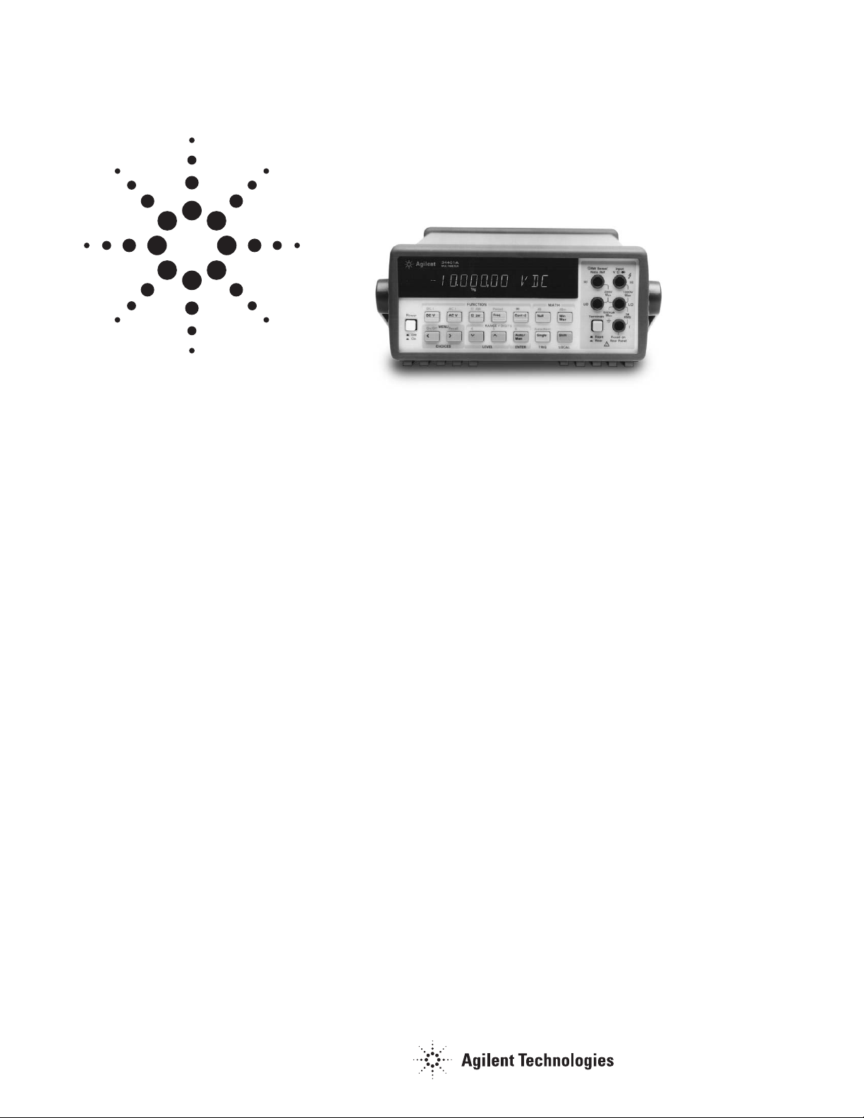
Agilent 34401A Multimeter
Uncompromising Performance
for Benchtop and System Testing
Product Overview
• Measure up to 1000 volts with
6
1
⁄2digits resolution
• 0.0015% basic dcV accuracy
(24 hour)
• 0.06% basic acV accuracy
(1 year)
• 3Hz to 300kHz ac bandwidth
• 1000 readings/sec. direct to GPIB
Superior performance
The Agilent Technologies 34401A
multimeter gives you the performance
you need for fast, accurate bench and
system testing. The 34401A provides
a combination of resolution, accuracy
and speed that rivals DMMs costing
many times more. 6
1
⁄2-digits of resolution, 0.0015% basic 24-hr dcV accuracy and 1,000 readings/sec direct to
GPIB assure you of results that are
accurate, fast, and repeatable.
Use it on your benchtop
The 34401A was designed with your
bench needs in mind. Functions commonly associated with bench operation, like continuity and diode test,
are built in. A Null feature allows you
to remove lead resistance and other
fixed offsets in your measurements.
Other capabilities like min/max/avg
readouts and direct dB and dBm
measurements make checkout with
the 34401A faster and easier.
The 34401A gives you the ability to
store up to 512 readings in internal
memory. For trouble-shooting, a
reading hold feature lets you
concentrate on placing your test
leads without having to constantly
glance at the display.
Use it for systems testing
For systems use, the 34401A gives
you faster bus throughput than any
other DMM in its class. The 34401A
can send up to 1,000 readings/sec
directly across GPIB in user-friendly
ASCII format.
You also get both GPIB and RS-232
interfaces as standard features.
Voltmeter Complete and External
Trigger signals are provided so you
can synchronize to other instruments
in your test system. In addition, a
TTL output indicates Pass/Fail
results when limit testing is used.
To ensure both forward and backward compatibility, the 34401A
includes three command languages
(SCPI, Agilent 3478A and Fluke
8840A /42A), so you don’t have to
rewrite your existing test software. An
optional rack mount kit is available.
Easy to use
Commonly accessed attributes, such
as functions, ranges, and resolution
are selected with a single button press.
Advanced features are available using
menu functions that let you optimize
the 34401A for your applications.
The included Agilent IntuiLink
software allows you to put your
captured data to work easily, using
PC applications such as Microsoft
Excel® or Word® to analyze, interpret,
display, print, and document the
data you get from the 34401A. You
can specify the meter setup and take
a single reading or log data to the
Excel spreadsheet in specified time
intervals. Programmers can use
ActiveX components to control the
DMM using SCPI commands. To find
out more about IntuiLink, visit
www.agilent.com/find/intuilink
1-year Warranty
With your 34401A, you get full
documentation, a high-quality test
lead set, calibration certificate with
test data, and a 1-year warranty,
all for one low price.
Page 2

2
Accuracy Specifications ± (% of reading + % of range)
[1]
Temperature
Coefficient
Frequency, 24 Hour
[2]
90 Day 1 Year 0°C – 18°C
Function Range
[3]
etc. 23°C ± 1°C 23°C ± 5°C 23°C ± 5°C 28°C – 55°C
dc Voltage 100.0000 mV 0.0030 + 0.0030 0.0040 + 0.0035 0.0050 + 0.0035 0.0005 + 0.0005
1.000000 V 0.0020 + 0.0006 0.0030 + 0.0007 0.0040 + 0.0007 0.0005 + 0.0001
10.00000 V 0.0015 + 0.0004 0.0020 + 0.0005 0.0035 + 0.0005 0.0005 + 0.0001
100.0000 V 0.0020 + 0.0006 0.0035 + 0.0006 0.0045 + 0.0006 0.0005 + 0.0001
1000.000 V 0.0020 + 0.0006 0.0035 + 0.0010 0.0045 + 0.0010 0.0005 + 0.0001
True rms 100.0000 mV 3 Hz - 5 Hz 1.00 + 0.03 1.00 + 0.04 1.00 + 0.04 0.100 + 0.004
ac Voltage
[4]
5 Hz - 10 Hz 0.35 + 0.03 0.35 + 0.04 0.35 + 0.04 0.035 + 0.004
10 Hz - 20 kHz 0.04 + 0.03 0.05 + 0.04 0.06 + 0.04 0.005 + 0.004
20 kHz - 50 kHz 0.10 + 0.05 0.11 + 0.05 0.12 + 0.04 0.011 + 0.005
50 kHz - 100 kHz 0.55 + 0.08 0.60 + 0.08 0.60 + 0.08 0.060 + 0.008
100 kHz - 300 kHz
[6]
4.00 + 0.50 4.00 + 0.50 4.00 + 0.50 0.20 + 0.02
1.000000 V 3 Hz - 5 Hz 1.00 + 0.02 1.00 + 0.03 1.00 + 0.03 0.100 + 0.003
to 5 Hz - 10 Hz 0.35 + 0.02 0.35 + 0.03 0.35 + 0.03 0.035 + 0.003
750.000 V 10 Hz - 20 kHz 0.04 + 0.02 0.05 + 0.03 0.06 + 0.03 0.005 + 0.003
20 kHz - 50 kHz 0.10 + 0.04 0.11 + 0.05 0.12 + 0.04 0.011 + 0.005
50 kHz - 100 kHz
[5]
0.55 + 0.08 0.60 + 0.08 0.60 + 0.08 0.060 + 0.008
100 kHz - 300 kHz
[6]
4.00 + 0.50 4.00 + 0.50 4.00 + 0.50 0.20 + 0.02
Resistance
[7]
100.0000 Ω 1 mA Current Source 0.0030 + 0.0030 0.008 + 0.004 0.010 + 0.004 0.0006 + 0.0005
1.000000 kΩ 1 mA 0.0020 + 0.0005 0.008 + 0.001 0.010 + 0.001 0.0006 + 0.0001
10.00000 kΩ 100 µA 0.0020 + 0.0005 0.008 + 0.001 0.010 + 0.001 0.0006 + 0.0001
100.0000 kΩ 10 µA 0.0020 + 0.0005 0.008 + 0.001 0.010 + 0.001 0.0006 + 0.0001
1.000000 MΩ 5.0 µA 0.002 + 0.001 0.008 + 0.001 0.010 + 0.001 0.0010 + 0.0002
10.00000 MΩ 500 nA 0.015 + 0.001 0.020 + 0.001 0.040 + 0.001 0.0030 + 0.0004
100.0000 MΩ 500 nA || 10MΩ 0.300 + 0.010 0.800 + 0.010 0.800 + 0.010 0.1500 + 0.0002
dc Current 10.00000 mA <0.1 V Burden Voltage 0.005 + 0.010 0.030 + 0.020 0.050 + 0.020 0.002 + 0.0020
100.0000 mA <0.6 V 0.010 + 0.004 0.030 + 0.005 0.050 + 0.005 0.002 + 0.0005
1.000000 A <1 V 0.050 + 0.006 0.080 + 0.010 0.100 + 0.010 0.005 + 0.0010
3.00000 A <2 V 0.100 + 0.020 0.120 + 0.020 0.120 + 0.020 0.005 + 0.0020
True rms 1.000000 A 3 Hz - 5 Hz 1.00 + 0.04 1.00 + 0.04 1.00 + 0.04 0.100 + 0.006
ac Current
[4]
5 Hz - 10 Hz 0.30 + 0.04 0.30 + 0.04 0.30 + 0.04 0.035 + 0.006
10 Hz - 5 kHz 0.10 + 0.04 0.10 + 0.04 0.10 + 0.04 0.015 + 0.006
3.00000 A 3 Hz - 5 Hz 1.10 + 0.06 1.10 + 0.06 1.10 + 0.06 0.100 + 0.006
5 Hz - 10 Hz 0.35 + 0.06 0.35 + 0.06 0.35 + 0.06 0.035 + 0.006
10 Hz - 5 kHz 0.15 + 0.06 0.15 + 0.06 0.15 + 0.06 0.015 + 0.006
Frequency 100 mV 3 Hz - 5 Hz 0.10 0.10 0.10 0.005
or Period
[8]
to 5 Hz - 10 Hz 0.05 0.05 0.05 0.005
750 V 10 Hz - 40 Hz 0.03 0.03 0.03 0.001
40 Hz - 300 kHz 0.006 0.01 0.01 0.001
Continuity 1000.0Ω 1mA Test Current 0.002 + 0.010 0.008 + 0.020 0.010 + 0.020 0.001 + 0.002
Diode Test
[9]
1.0000V 1mA Test Current 0.002 + 0.010 0.008 + 0.020 0.010 + 0.020 0.001 + 0.002
[1] Specifications are for 1hr warm-up and 61⁄2digits, Slow ac filter.
[2] Relative to calibration standards.
[3] 20% over range on all ranges except 100 0 Vdc and 750 Vac ranges.
[4] For sinewave input > 5% of range. For inputs from 1% to 5% of range
and < 50 kHz, add 0.1% of range additional error.
[5] 750 V range limited to 100 kHz or 8 x10⁷ Volt-Hz.
[6] Typically 30% of reading error at 1 MHz.
[7] Specifications are for 4-wire ohms function or 2-wire ohms using Math Null.
Without Math Null, add 0.2 Ω additional error in 2-wire ohms function.
[8] Input >100 mV. For 10 mV to 100 mV inputs multiply % of reading error x10.
[9] Accuracy specifications are for the voltage measured at the input terminals only.
1mA test current is typical. Variation in the current source will create some variation
in the voltage drop across a diode junction.
254.4 mm
212.6 mm
103.6 mm
374.0 mm
88.5 mm
348.3 mm
Page 3

3
Measurement Characteristics
dc Voltage
Measurement Method:
Continuously Integrating Multi-slope III
A-D Converter
A-D Linearity:
0.0002% of reading + 0.0001% of range
Input Resistance:
10 MΩ or 0.1V, 1V, 10 V ranges:
Selectable >10,000 MΩ
100 V, 1000 V ranges:
10 MΩ ±1%
Input Bias Current:
< 30pA at 25° C
Input Protection:
1000 V all ranges
dcV:dcV Ratio Accuracy:
V
input
Accuracy + V
reference
Accuracy
True rms ac Voltage
Measurement Method:
ac coupled True rms – measures the ac
component of the input with up to 400 Vdc
of bias on any range
Crest Factor:
Maximum of 5:1 at Full Scale
Additional Crest Factor Errors (non-sinewave):
Crest Factor 1–2: 0.05 % of reading
Crest Factor 2–3: 0.15 % of reading
Crest Factor 3–4: 0.30 % of reading
Crest Factor 4–5: 0.40 % of reading
Input Impedance:
1 MΩ ± 2% in parallel with 100 pF
Input Protection:
750 Vrms all ranges
Resistance
Measurement Method:
Selectable 4-wire or 2-wire Ohms.
Current source referenced to LO input.
Maximum Lead Resistance (4-wire):
10% of range per lead for 100Ω and 1kΩ
ranges. 1kΩ per lead on all other ranges.
Input Protection:
1000 V all ranges
dc Current
Shunt Resistance:
5Ω for 10 mA,100 mA; 0.1 Ω for 1 A, 3 A
Input Protection:
Externally accessible 3 A 250 V Fuse
Internal 7 A 250 V Fuse
[1] For 1kΩ unbalance in LO lead.
[2] For power line frequency ± 0.1%.
[3] For power line frequency ± 1% use 40dB or
± 3% use 30dB.
[4] Reading speeds for 60Hz and (50Hz) operation.
[5] Maximum useful limit with default settling
delays defeated.
[6] Speeds are for 4
1
⁄2digits, Delay 0, Auto-zero
and Display OFF.
True rms ac Current
Measurement Method:
Direct coupled to the fuse and shunt.
ac coupled True rms measurement
(measures the ac component only).
Shunt Resistance:
0.1 Ω for 1 A and 3 A ranges
Input Protection:
ExternalIy accessible 3 A 250 V Fuse
Internal 7 A 250 V Fuse
Frequency and Period
Measurement Method:
Reciprocal counting technique
Voltage Ranges:
Same as ac Voltage Function
Gate Time:
1 s, 100 ms, or 10 ms.
Continuity / Diode
Response Time:
300 samples/s with audible tone
Continuity Threshold:
Selectable from 1 Ω to 1000 Ω
Measurement Noise Rejection 60 (50) Hz
[1]
dc CMRR: 140 dB
ac CMRR: 70 dB
Integration Time and Normal Mode Rejection
[2]
100 plc / 1.67 s (2 s): 60 dB
[3]
10 plc / 167 ms (200 ms): 60 dB
[3]
1 plc / 16.7 ms (20 ms): 60 dB
<1 plc / 3 ms or 800 µs: 0 dB
Operating Characteristics
[4]
Function Digits Readings/s
dcV, dcI, and 61⁄
2
0.6 (0.5)
Resistance 61⁄
2
6 (5)
51⁄
2
60 (50)
51⁄
2
300
41⁄
2
1000
acV, acI 61⁄
2
0.15 Slow (3Hz)
61⁄
2
1Medium (20Hz)
61⁄
2
10 Fast (200Hz)
61⁄
2
50
[5]
Frequency or 61⁄
2
1
Period 51⁄
2
9.8
41⁄
2
80
System Speeds
[6]
Configuration Rates: 26/s to 50/s
Autorange Rate (dc Volts): > 30/s
ASCII readings to RS-232: 55/s
ASCII readings to GPIB: 1000/s
Maximum Internal Trig. Rate: 1000/s
Max.Ext.Trig.Rate to Memory: 1000/s
Triggering and Memory
Reading HOLD Sensitivity:
10%, 1%, 0.1%,or 0.01% of range
Samples/ trigger:
1 to 50,000
Trigger Delay:
0 to 3600 s: 10 µs step size
External Trigger Delay:
< 1 ms
External Trigger Jitter:
< 500 µs
Memory:
512 readings
Math Functions
NULL, Min/Max/Average, dBm, dB,
Limit Test (with TTL output)
Standard Programming Languages
SCPI (IEEE-488.2), Agilent 3478A,
Fluke 8840A/42A
Accessories Included
Test Lead Kit with probe, alligator,
and grabber attachments.
Operating Manual, Service Manual, test report,
and power cord.
General Specifications
Power Supply:
100 V/120 V/220 V/240 V ±10%
Power Line Frequency:
45 Hz to 66 Hz and 360 Hz to 440 Hz
Automatically sensed at power-on
Power Consumption:
25 VA peak (10 W average)
Operating Environment:
Full accuracy for 0° C to 55° C
Full accuracy to 80% R.H. at 40° C
Storage Environment:
– 40° C to 70° C
Weight:
3.6 kg (8.0 Ibs)
Safety:
Designed to CSA, UL-1244, IEC-348
RFI and ESD:
MIL-461C, FTZ 1046, FCC
Vibration and Shock:
MIL-T-28800E, Type III, Class 5 (Sine Only)
Warranty:
1 year
Page 4

Ordering Information
Agilent 34401A Multimeter
Accessories included
Test Lead Kit with probe, alligator, and
grabber attachments, operating manual,
service manual, calibration certificate,
test report, and power cord.
Options
34401A-1CM
Rack Mount Kit* (P/N 5062-3972)
34401A-OBO
DMM without manuals
34401A-A6J
ANSI Z540 compliant calibration
Manual options (please specify one)
34401A-ABA US English
34401A-ABD German
34401A-ABE Spanish
34401A-ABF French
34401A-ABJ Japanese
34401A-ABZ Italian
34401A-AB0 Taiwan Chinese
34401A-AB1 Korean
34401A-AB2 Chinese
34401A-AKT Russian
Agilent Accessories
11059A Kelvin Probe set
11060A Surface Mount Device (SMD)
test probes
11062A Kelvin clip set
34131 Hard transit case
34161A Accessory pouch
34171A Input terminal connector
(sold in pairs)
34172A Input calibration short
(sold in pairs)
34330A 30 A current shunt
E2308A 5K thermistor probe
*
For racking two side-by-side,
order both items below:
Lock link kit (P/N 5061-9694)
Flange kit (P/N 5063-9212)
www.agilent.com/find/emailupdates
Get the latest information on the products and
applications you select.
Agilent T&M Software and Connectivity
Agilent's Test and Measurement software and
connectivity products, solutions and developer
network allows you to take time out of connecting
your instruments to your computer with tools
based on PC standards, so you can focus on your
tasks, not on your connections.
Visit
www.agilent.com/find/connectivity
for more information.
Agilent's IO Libraries Suite ships with the 34401A
to help you quickly establish an error-free connection between your PC and instruments–regardless
of the vendor. It provides robust instrument control
and works with the software development environment you choose.
For additional description of Agilent's
IO Libraries Suite features and installation
requirements, please go to:
www.agilent.com/find/iosuite-datasheet
Product specifications and descriptions in
this document subject to change without notice.
© Agilent Technologies, Inc. 1998, 2000, 2005
Printed in the U.S.A. May 1, 2005
5968-0162EN
Agilent Technologies’ Test and Measurement
Support, Services, and Assistance
Agilent Technologies aims to maximize the value
you receive, while minimizing your risk and problems.
We strive to ensure that you get the test and
measurement capabilities you paid for and obtain
the support you need. Our extensive support
resources and services can help you choose the
right Agilent products for your applications and
apply them successfully. Every instrument and
system we sell has a global warranty. Two
concepts underlie Agilent's overall support policy:
"Our Promise" and "Your Advantage."
Our Promise
Our Promise means your Agilent test and
measurement equipment will meet its advertised
performance and functionality. When you are
choosing new equipment, we will help you with
product information, including realistic performance
specifications and practical recommendations from
experienced test engineers. When you receive your
new Agilent equipment, we can help verify that it
works properly, and help with initial product
operation.
Your Advantage
Your Advantage means that Agilent offers a wide
range of additional expert test and measurement
services, which you can purchase according to your
unique technical and business needs. Solve
problems efficiently and gain a competitive edge by
contracting with us for calibration, extra-cost
upgrades, out-of-warranty repairs, and onsite
education and training, as well as design, system
integration, project management, and other
professional engineering services. Experienced
Agilent engineers and technicians worldwide can
help you maximize your productivity, optimize the
return on investment of your Agilent instruments
and systems, and obtain dependable measurement
accuracy for the life of those products.
Get assistance with all your test and measurement
needs at:
www.agilent.com/find/assist
Microsoft is a U.S. registered trademark
of Microsoft Corporation.
 Loading...