

Drucktransmitter
für flüssige und gasförmige Medien, 2-Le i t e r - S y s t e m
Montage- und Bedienungsanleitung
T y p e n -
re i h e
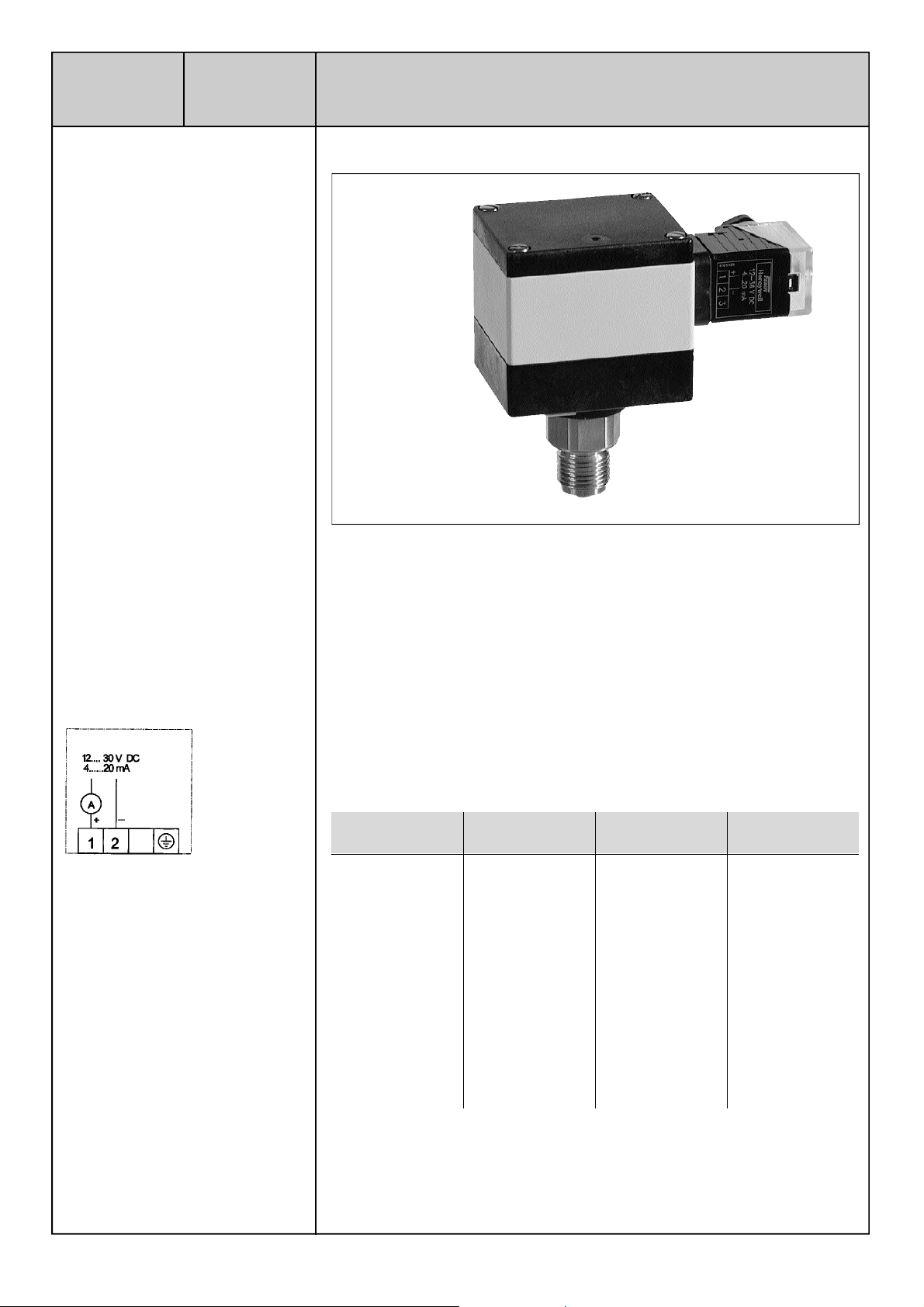
SN…-280
Te ch n i s c he Daten
Le i t u n g s d o s e
S t e ck e r a n s chluss DIN 436 50 PG 11
B e t r i e b s s p a n n u n g
12 V … 30 V DC
U m g e b u n g s t e m p e r a t u r
0…+60 °C
M a t e r i a l
G e h ä u s e : M a k r o l o n
Fü h l e r : 1. 4 571
M e m b r a n : 1. 4 4 35
S ch u t z a r t
IP 65
Zubehör im Lieferumfang e nthalten
S t e cker DIN 4365 0
Pro z e ß a n s c h u s s
G | a u ß e n
S ch l ü s s e l w e i t e
27
Li n e a r i t ä t
1 % FS (Fe s t p u n k t g e r a d e )
Kompensi erter Bere i c h
0 – 100 °C
A n s p r e c h z e i t
10 ms
Max. Mediumtemperatur
– 3 0 … + 110 ° C
M e ß p r i n z i p
P i e z o r e s i s t i v
S t e c k e r a n s ch l u s s
SN … - 2 8 0
Die Versorgungs spannu ng ist an den
Klemmen 1+/2– anzusch l i e ß e n .
M o n t a g e
Direkt auf Druck l e i t u n g
A u s g a n g s s i g n a l
4…20 mA , Bürde (UB– 10 V)/0,0 2 A
G e s a m t g e n a u i g k e i t
1 % FS (Fe s t p u n k t g e r a d e )
Wi r k u n g s r i ch t u n g
Steigender Druck ergibt steigendes
A u s g a n g s s i g n a l
1. M o n t a g e
Die Transmitter der SN-Baureihe werden direkt auf die Rohr- oder Druckleitun g
m o n t i e r t .
A ch t u n g !
Nur mit Sch r a u b e n s chlüssel am Sechskant des Druckfühlers anziehen. Niemals am
Gehäuse drehen oder dieses als Hebelarm benutze n.
2 . E l e k t r i s cher Ansch l u s s
Das Gerät kann mi t 12 bis 30 V DC gespeist werden. Bei der Verwendung eines
Netzteils ist unbedingt auf die richtige Polarität zu achten. Bei fehlerhaftem
A n s chluß kann das Gerät zerstört werden.
A ch t u n g !
Niemals eine Spannung höher a ls 30 V DC an die Klemmen anlegen.
f
D r u c k a n s chluss G | a u ß e n
A r b e i t s b e re i ch A r b e i t s b e re i ch Max. Druck T y p
(b a r ) (K p a ) (b a r )
0 – 0 , 2 5 0 – 2 5 0 ,75 SN 025 – 2 8 0
0 – 0 , 6 0 – 6 0 1, 8 SN 06 – 2 8 0
0 – 1 0 – 10 0 3 SN 1–28 0
0 – 1, 6 0 – 16 0 6 , 4 SN 2–28 0
0 – 2 , 5 0 – 2 5 0 7, 5 SN 3–28 0
0 – 4 0 – 4 0 0 16 SN 4–28 0
0 – 6 0 – 6 0 0 18 SN 6–28 0
0 – 10 0 – 10 0 0 3 0 SN 10 – 2 8 0
0 – 16 0 – 16 0 0 4 8 SN 16 – 2 8 0
0 – 2 5 0 – 2 5 0 0 70 SN 25 – 2 8 0
0 – 4 0 0 – 4 0 0 0 8 0 S N 40–28 0
FE M A R e g e l g e r ä t e
Honeywell GmbH · Böbli nger Straße 17 · D-71101 Sch ö n a i ch
Telefon 0 70 31 / 6 37- 02 · Telefax 0 70 31/ 6 37- 8 5 0
MU2B-0276GE51 R1005 7157 338/6

Pressure transmitters
for liquid and gaseous media, 2-wire system
Fitting and Operation Instruction
T y p e
s e r i e s
SN…-280
Te chnical data
Cable entry
Plug connection DI N 43 650 PG 11
Oper ation volta g e
12 … 30 V DC
Ambient tempe rature
0…+60 °C
M a t e r i a l s
H o u s i n g : M a k r o l o n
Sensor housing: 1. 4 571
Pressure me mbrane: 1. 4 4 35
Protection class
IP 65
Accesso ries included i n delive ry
Plug DIN 436 50 female
Pre s s u re connection
G | m a l e
W re n c h size
27
I n s t a l l a t i o n
Direct on pressure line
Li n e a r i t y
1 % FS (straight line)
C o m p e n s ated rang e
0 – 100 °C
Propagation de lay
10 ms
Max. medium temp.
– 3 0 … + 110 ° C
Measuring method
P i e z o r e s i s t i v e
Connection diagram
SN … - 2 8 0
Connect the supply voltage of
10–30 V to the terminals 1+/2–
(measuring circuit)
Output signal
4…20 mA , Load (UB– 10 V)/0.02 A
D i r ection o f action
Risi ng pressure f risi ng output signal
Manufactu red for and on behalf of the
Envi ronm ental and Combusition C ont rols
Division of Hone ywell Te chnologies Sàrl
Ecublens, Route du Bois 37, Switz erland
by it s Authorized Repre sentative.
1. F i t t i n g
The series SN transm itters are f itted directly to the pipeline or the pressure
v e s s e l .
A t t e n t i o n !
Tighten only with the screwdriver applied to the he xagon of the pressure se nsor.
Do not turn the housing. Never u se housin g as lever a rm!
2 . Electrical wiring
The unit is supplied with 12 to 30 V DC. With a DC power supply pay attention to
correct polarity. The dev ice can be destroyed if the connection is faulty.
A t t e n t i o n !
Never apply a voltage higher 30 V to one of the termi nals.
f
Press ure connection thread G | m a l e
Working range Working range Max. T y p e
(nominal range) (nominal range) p re s s u re
(b a r ) (K p a ) (b a r )
0 – 0 . 2 5 0 – 2 5 0 . 75 SN 025 – 2 8 0
0 – 0 . 6 0 – 6 0 1. 8 SN 06 – 2 8 0
0 – 1 0 – 10 0 3 SN 1–28 0
0 – 1. 6 0 – 16 0 6 . 4 SN 2–28 0
0 – 2 . 5 0 – 2 5 0 7. 5 SN 3–28 0
0 – 4 0 – 4 0 0 16 SN 4–28 0
0 – 6 0 – 6 0 0 18 SN 6–28 0
0 – 10 0 – 10 0 0 3 0 SN 10 – 2 8 0
0 – 16 0 – 16 0 0 4 8 SN 16 – 2 8 0
0 – 2 5 0 – 2 5 0 0 70 SN 25 – 2 8 0
0 – 4 0 0 – 4 0 0 0 8 0 S N 40–28 0
FE M A R e g e l g e r ä t e
Honeywell GmbH · Böbli nger Straße 17 · D-71101 Sch ö n a i ch
Telefon 0 70 31 / 6 37- 02 · Telefax 0 70 31/ 6 37- 8 5 0
MU2B-0276GE51 R1005 7157 338e/6
 Loading...