

Page 1
Honeywell
T8775A,C
TheDigitalRoundTM
Non-ProgrammableThermostats
The T8775A,C Thermostats provide single-stage
temperature control for 24V systems. The
T8775A,C models include a thermostat, wallplate
(for wiring and mounting thermostat), mounting
screws, wall anchors, and a 4074 FAB resistor.
MERCURYNOTICE
If this control is replacing a control that
contains mercury in a sealed tube, do not
place your old control in the trash.
Contact your local waste management
authority for instructions regarding
recycling and the proper disposal of an old
control containing mercury in a sealed
tube.
Location
install the thermostat about 5 ft (1.5m) above the
floor in an area with good air circulation at average
temperature. Do not install the thermostat where it
can be affected by:
-- drafts or dead spots behind doors and in
corners.
-- hot or cold air from ducts.
-- radiant heat from the sun or appliances.
-- concealed pipes and chimneys.
-- unheated (uncooled) areas such as an outside
wall behind the thermostat.
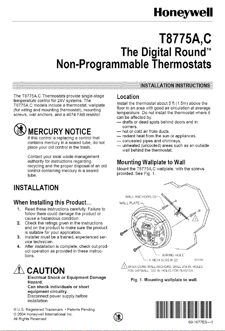
MountingWallplatetoWall
Mount the T8775A,C wallplate, with the screws
provided. See Fig. 1.
INSTALLATION
WALL ANCHORS (2) --
When Installingthis Product...
1. Read these instructions carefully. Failure to
follow them could damage the product or
cause a hazardous condition.
2. Check the ratings given in the instructions
and on the product to make sure the product
is suitable for your application.
3. installer must be a trained, experienced ser-
vice technician.
4. After installation is complete, check out prod-
uct operation as provided in these instruc-
tions.
z_ CAUTION
Electrical Shock or Equipment Damage
Hazard.
Dan shock individuals or short
equipment circuitry.
Disconnect power supply before
installation.
© U.S Registered Trademark ° Patents Pending
© 2004 Honeywell International inc.
All Rights Reserved _ 69-1677ES--1
WALL PLATE _
I
I INCI/SCREW (2) M_ ,>
z_WHEN USING WALL ANCHORS, DRILL 3,¸¸16 IN HOLES
FOR DRYWALL¸ 7/32 IN HOLES FOR PLASTER¸
Fig. 1. Mounting watlplate to wall.
Page 2
T8775A, C THE DIGITAL ROUND TM NON-PROGRAMMABLE THERMOSTATS
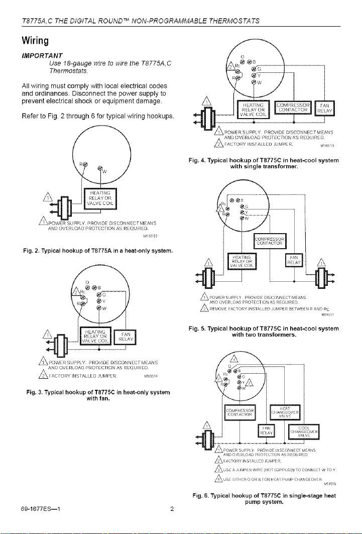
Wiring
IMPORTANT
Use 18-gauge wire to wire the T8775A, C
Thermostats
All wiring must comply with local electrical codes
and ordinances. Disconnect the power supply to
prevent electrical shock or equipment damage.
Refer to Fig. 2 through 6 for typical wiring hookups.
AND OVERLOAD PROTEC[ ON AS REQU RED
Fig. 2. Typical hookup of T8775A in a heat-only system.
APOWEf_SUP>LY Pf_OVDE DSCONNECTMEANS
Fig, 3. Typical hookup of T8775C in heat-only system
with fan.
r4_{_ s
Fig. 4. Typical hookup of T8775C in heat=cool system
with single transformer.
A A
A;,OWE_ SUPPLY P_OWOE O_SCONN_CT MZANS
ANO OW_L OAO ;'_OTECT_ON AS _EOU_EO
A _EMOW _ACTO_Y _NSTAHEOJUMPZ_ BETWEEN _ ANO _C
Fig. 5. Typical hookup of T8775C in heat=cool system
with two transformers.
A
6g-1677ES--1 2
Fig. 6. Typical hookup of T8775C in single-stage heat
pump system.
Page 3

T8775A, C THE DIGITAL ROUND T._NON-PROGRAMMABLE THERMOSTATS
CUSTOMIZETHERMOSTAT
SettingFuel Switch(T8775Conly)
The fuel switch is preset at the factory in the F
position See Fig. 7. This is the correct setting for gas
or oil systems• tf the T8775C is being installed on an
electric heat system, or a heat pump, set the switch to
the E position The E setting allows the fan to turn on
immediateIy with the heating equipment in a system
where the G terminal is connected•
° i
Fig. 7. Fuel switch.
DIPSwitch
To adjust the heat cycle rate or the Fahrenheit/Celsius
indication, locate DIP switch 1,2 and 3 on the back of
the thermostat See Fig. 8
Table 1. Heat Cycle Rate.
Cycles DiP DIP
Per Switch Switch
Heating System
Steam, Gravity
High Efficiency Warm Air
_0%+ efficiency), Hot Water,
Heat Pump
Gas or Oil Warm Air (factory Off Off
setting)
Electric Warm Air On Off
in Floor Radiant Heat CheckwJth manufacturer
Hour 1 2
On On
Off On
for recommended cycle
rate.
Fahrenheit/Celsius Indication
Use DIP switch 3 to set the desired temperature
indication. See Table 2
Table 2. Temperature Indication.
FahrenheitlCelsius
Display DiP Switch 3
Fahrenheit (factory setting) Off
Celsius On
MountingThermostat to Wallplate
ENGAGE TABS
AT BOTTOM O_
AND WALL ;LA rE
PRESS UPPER \
EDGE Of CASE
Fig. 8. DIP switch.
Set HeatCycle Rate
Use DIP switches 1 and 2 to set the heat cycle rate.
See Table 1.
Fig. 9. Mounting thermostat to wallplate.
OPERATION
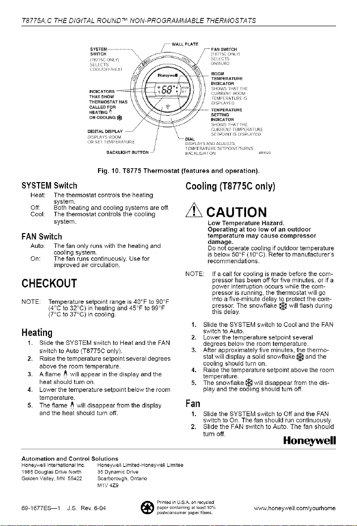
SettingSYSTEMand FAN Switches
(T8775Conly)
System and fan settings are controlled manually by
using the switches located at the top of the
thermostat. See Fig. 10.
3 69-I677ES--1
Page 4
T8775A, C THE DIGITAL ROUND TM NON-PROGRAMMABLE THERMOSTATS
SYSTEM
(18_5C ONLYi
S_LECIS _
INDICATORS
THERMOSTATHAS
CALLEDF_R
HEATING
ORCOOtJNG_
THATSHOW _
DIGITALDISPLAY_
b_SPLAY8ROOM
ORSE] ]EM_'ERAIU_E
BACKI-IGHTBUTTON
Fig. 10. T8775 Thermostat (features and operation).
SYSTEMSwitch
Heat: The thermostat controls the heating
system.
Off: Both heating and cooling systems are off
Cool: The thermostat controls the cooling
system.
FANSwitch
Auto: The fan only runs with the heating and
cooling system.
On: The fan runs continuously Use for
improved air circulation.
CHECKOUT
NOTE: Temperature setpoint range is 40°F to 90°F
(4°C to 32°C) in heating and 45°F to 99°F
(7°C to 37°C) in cooling.
Heating
1. Slide the SYSTEM switch to Heat and the FAN
switch to Auto (T8775C only).
2. Raise the temperature setpoint severaldegrees
above the room temperature.
3. A flame r_ will appear in the display and the
heat should turn on.
4. Lower the temperature setpoint below the room
temperature.
5. The flame t_ will disappear from the display
and the heat should turn off.
Automation and Control Solutions
Honeywetl International Inc Honey_vell Limited-Honeywell Limitee
1985 Douglas Drive North 35 Dynamic Drive
Golden Valley, MN 55422 Scarborough, Ontario
M1V 4Z9
DIAL
D_SPLAYSAN A JUSIS
I EMPERAI URE SEI PO_NId J_NS
BAC_ _GH ] ON
Cooling (T8775Conly)
zL
CAUTION
Low Temperature Hazard.
Operating at too low of an outdoor
temperature may cause compressor
damage.
Do not operate cooling if outdoor temperature
is below 50°F (10°C). Refer to manufacturer's
recommendations.
NOTE:
If a calt for cooling is made before the com-
pressor has been off for five minutes, or if a
power interruption occurs while the com-
pressor is running, the thermostat will go
into a five-minute delay to protect the com-
pressor. The snowflake _ will flash during
this deIay.
1. Slide the SYSTEM switch to Coot and the FAN
switch to Auto.
2. Lower the temperature setpoint several
degrees below the room temperature.
3. After approximately five minutes, the thermo-
stat wilt display a solid snowflake _ and the
cooling should turn on.
4. Raise the temperature setpoint above the room
temperature.
5. The snowflake _witl disappear from the dis-
play and the cooling should turn off.
Fan
1. Slide the SYSTEM switch to Off and the FAN
switch to On. The fan should run continuously
2. Slide the FAN switch to Auto. The fan should
turn off.
Honeywell
69-1677ES--1 J.S. Rev6-04 papercontainingatleastlo% _wwv.honeywelLoom/yourhome
_ Pdnted _n U.S.A. on recycled
post-consumer paper fibers.
 Loading...