

Honeywell MS7120 Installation And User Manual

MS7120
Orbit® Presentation Laser Scanner
Installation and User’s Guide

Disclaimer
Honeywell International Inc. (“HII”) reserves the right to make changes in
specifications and other information contained in this document without prior
notice, and the reader should in all cases consult HII to determine whether any
such changes have been made. The information in this publication does not
represent a commitment on the part of HII.
HII shall not be liable for technical or editorial errors or omissions contained
herein: nor for incidental or consequential damages resulting from the furnishing,
performance, or use of this manual.
This document contains propriety information that is protected by copyright. All
rights reserved. No part of this document may be photocopied, reproduced, or
translated into another language without the prior written consent of HII.
© 2009 Honeywell International Inc. All rights reserved.
Web Address: www.honeywellaidc.com
Trademarks
Metrologic, MetroSelect, and MetroSet2 are trademarks or registered trademarks
of Metrologic Instruments, Inc. or Honeywell International Inc.
Microsoft, Windows, and Windows 95 are trademarks or registered trademarks of
Microsoft Corporation.
IBM is a trademark of International Business Machines Corporation.
Other product names mentioned in this manual may be trademarks or registered
trademarks of their respective companies and are the property of their respective
owners.
Patents
Please refer to page 34 for a list of patents.

TABLE OF CONTENTS
Introduction
Product Overview ............................................................................................. 1
Scanner and Accessories................................................................................. 2
Scanner Components....................................................................................... 4
Cable Removal.................................................................................................4
Caution and Serial Number Labels................................................................... 5
Maintenance..................................................................................................... 5
Mounting Specifications ................................................................................... 6
Installation
RS232, or Light Pen ......................................................................................... 7
RS485 .............................................................................................................. 8
Keyboard Wedge.............................................................................................. 9
Stand-Alone Keyboard Wedge....................................................................... 10
Full Speed or Low Speed USB.......................................................................11
Scanner Operation
Indicators
Audible ....................................................................................................... 12
Visual ......................................................................................................... 13
Failure ........................................................................................................ 14
Depth of Field Specifications
Normal Scan Zone ..................................................................................... 15
Reduced Scan Zone................................................................................... 15
Depth of Field by Bar Code Element Width
Normal Scan Zone ..................................................................................... 16
Reduced Scan Zone................................................................................... 17
Troubleshooting Guide ....................................................................................... 18
Design Specifications ......................................................................................... 22
Applications and Protocols ................................................................................. 24
ii

TABLE OF CONTENTS
Scanner Configuration........................................................................................ 25
Configuration Modes ...................................................................................... 25
Bar Codes .................................................................................................. 25
MetroSet2................................................................................................... 25
Serial Configuration.................................................................................... 25
Upgrading the Firmware..................................................................................... 26
Scanner and Cable Terminations
Scanner Pinout Connections.......................................................................... 27
Cable Connector Configurations (Host End) .................................................. 28
Regulatory Compliance
Safety ............................................................................................................. 30
EMC ............................................................................................................... 31
Limited Warranty ................................................................................................ 33
Patents ............................................................................................................... 34
Index .................................................................................................................. 35
Customer Support .............................................................................................. 37
Technical Assistance...................................................................................... 37
Product Service and Repair............................................................................ 38
iii

INTRODUCTION
®
is an aggressive, omnidirectional laser bar code scanner ideal for use in
Orbit
retail, convenience, liquor and specialty stores Designed to be lightweight and
rugged, Orbit’s small size makes it ideal for applications where counter space is
limited. The MS7120 unique contoured shape allows it to be picked-up and used
as a hand-held scanner when scanning large or bulky items.
Key Product Features
Fully Automatic Scanning Operation
Adjustable Scan Head
User-Replaceable Single Cable Interface To Host (Powerlink Compatible)
Seven Beeper Tones
Configurable Depth of Field
Firmware updates are easily loaded into Flash memory
OPOS and JPOS System Compatible
Support For Common Interfaces Including USB (See Table Below)
Easy Bar Code Configuration
ORBIT
MODEL NUMBER
MS7120-38
RS232 Low Speed USB,
Keyboard Emulation Mode or Serial Emulation Mode*
INTERFACE
MS7120-41 RS232/Light Pen Emulation
MS7120-47
Keyboard Wedge,
Stand-Alone Keyboard and RS232 Transmit/Receive
MS7120-106 RS485 and Full Speed USB
* Configurable for Keyboard Emulation Mode or Serial Emulation Mode.
Default setting is Keyboard Emulation Mode.
Applicable for IBM® Host applications.
1

INTRODUCTION
Scanner and Accessories
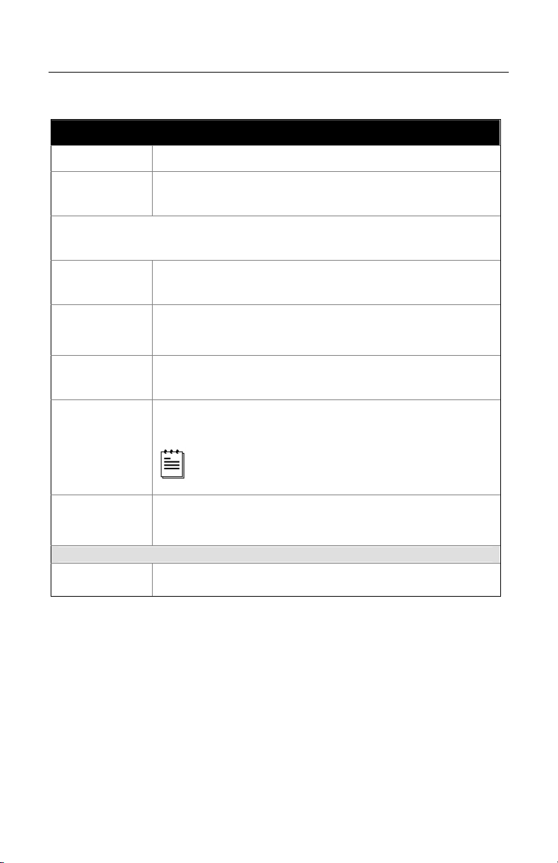
BASIC KIT COMPONENTS
Part No. Description
MS7120 Orbit Presentation Laser Bar Code Scanner
00-02282x
MS7120 Orbit Presentation Laser Bar Code Scanner
Installation and User’s Guide
00-02407x MetroSelect® Configuration Guide
* Guides also available for download at www.honeywellaidc.com.
OPTIONAL ACCESSORIES
Part No. Description
AC to DC Power Transformer - Regulated 5.2VDC @ 1A output.
46-00525 90VAC to 255VAC United States, Canada and Japan
46-00526 90VAC to 255VAC Continental European
46-00527 90VAC to 255VAC United Kingdom
46-00528 90VAC to 255VAC Australia
46-00529 90VAC to 255VAC China
46-00530 90VAC to 255VAC India
59-59000x -3
Other items may be ordered for the specific protocol being used. To order additional items,
contact the dealer, distributor or customer service representative
RS232 PowerLink Cable with Built in Power Jack
straight cord, short strain relief
.
2
INTRODUCTION
Scanner and Accessories
OPTIONAL ACCESSORIES
Part No. Description
MVC**
RS485 Applications
MVC Cable ±12VDC to +5.2VDC
** Contact a customer service representative for additional information on
the MVC cable series and the host connections available.
59-59002x-3
59-59020x-3
54-54213x-N-3
Keyboard Wedge PowerLink Cable
straight cord, short strain relief
Stand Alone Keyboard PowerLink Cable
straight cord, short strain relief
USB Full Speed Cable, Locking Plus-Power
straight cord, short strain relief
™
Type A
USB Full Speed Cable, Locking Plus-Power™ Type A
straight cord, short strain relief
54-54214x-N-3
This cable is for use with full speed
USB (-106) interface only.
59-59235x-N-3
USB Low Speed Communication Cable, Type A
straight cord, short strain relief
45-45619 Counter/Wall Mount Kit
Other items may be ordered for the specific protocol being used. To order additional items,
contact the dealer, distributor or customer service representative.
3
INTRODUCTION
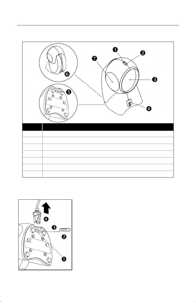
Scanner Components
ITEM NO
1 White LED (see page 12)
2 Blue LED (see page 12)
3 Red Output Window (Laser Aperture)
4 Speaker (see page 12)
5 Pin Hole for Cable Release
6 10-Pin RJ45, Female Socket (see page 28)
7 Adjustable Scan Head, 30°
Figure 1. Scanner Components
Cable Removal
1.
2. Bend an ordinary paperclip into the shape
3. Insert the paperclip into the small ‘pin-hole’.
4. There will be a faint ‘click’ when the cable
DESCRIPTION
Locate the small ‘pin-hole’ on the bottom of
the scanner near the cable.
shown.
lock is released. Pull gently on the strainrelief of the PowerLink cable to remove it
from the scanner.
Figure 2. Cable Release
4
INTRODUCTION
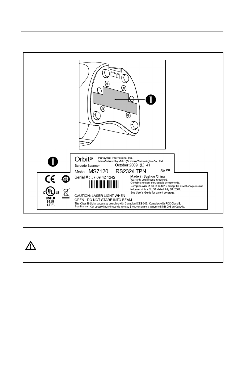
Caution and Serial Number Labels
Figure 3. Labeling Locations on the Bottom of the Scanner and Examples
Caution
To maintain compliance with applicable standards, all circuits connected to the scanner must
meet the requirements for SELV (Safety Extra Low Voltage) according to EN/IEC 60950-1.
To maintain compliance with standard CSA C22.2 No. 60950-1/UL 60950-1 and norm
EN/IEC 60950-1, the power source should meet applicable performance requirements for a
limited power source.
Maintenance
Smudges and dirt on the unit's window can interfere with the unit's performance.
If the window requires cleaning, use only a mild glass cleaner containing no
ammonia. When cleaning the window, spray the cleaner onto a lint free, nonabrasive cleaning cloth then gently wipe the window clean.
If the unit's case requires cleaning, use a mild cleaning agent that does not
contain strong oxidizing chemicals. Strong cleaning agents may discolor or
damage the unit's exterior.
5

INTRODUCTION INTRODUCTION
Mounting Specifications
Optional Wall/Counter Mount
Item Description Qty.
a. Locking Plate, PN 50-50302 1
b. Base Cover, PN 50-50301 1
c. #7 x 1.00" Wood Screw, PN 18-18013 3
d. M3 x 8 mm Flathead Screw, PN 18-18004 4
1. Drill three #39 pilot holes.
Note the position Orbit will rest
(see Figure 5). Use the dimensions
provided in Figure 5 or the locking
plate as a template to drill three
#39 pilot holes in the mounting
surface.
2. Attach the locking plate to the wall/counter.
Secure the locking plate to the counter/wall with the three #7 x 1.00" wood
screws provided (see Figure 6).
3. Attach the base plate to the Orbit.
Secure the base cover to the bottom of Orbit using the four M3 x 8 mm
screws provided (see Figure 7).
4. Mount
Orbit to the locking plate.
Hold Orbit 90° clockwise from the desired position then lower it over the
locking plate until it sits flush to the countertop. Twist Orbit counter
clockwise 90° to lock the scanner in place (see Figure 8).
Figure 4. Kit Components
Figure 5
6
Figure 6
Figure 7
Figure 8
INSTALLATION
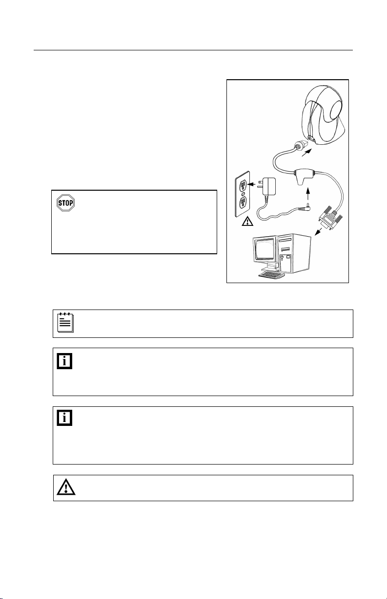
RS232, Light Pen Emulation
Turn off the host device.
1.
2. Plug the male 10-pin RJ45 end
of the PowerLink cable into the
10-pin socket on the MS7120.
3. Connect the 9-pin female end of the
PowerLink cable to the host device.
4. Plug the external power supply into the
power jack on the PowerLink cable.
Check the AC input requirements
of the power supply to make sure
the voltage matches the AC outlet.
The outlet must be located near
the equipment and be easily
accessible.
5. Connect AC power to the transformer.
6. Turn on the host device.
Figure 9.
When the scanner first receives power, the blue and white LED will
toggle on and off then the scanner will beep once.
Plugging the scanner into the serial port of the PC does not guarantee
that scanned information will appear at the PC. A software driver and
correct configuration setting are also required for proper
communication to occur.
Powering the MS7120 directly from the host device can cause
interference with the operation of the scanner or the computer. Not
all computers supply the same current. For this reason, Honeywell
recommends using an external power supply. For additional
information contact a Honeywell customer service representative.
See page 5.
7
INSTALLATION
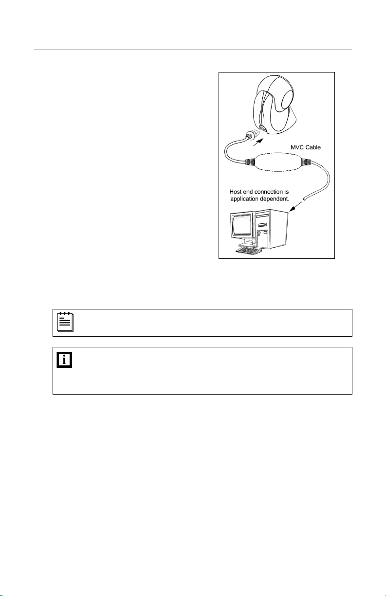
RS485
Turn off the host device.
1.
2. Plug the male 10-pin RJ45 end
of the MVC cable into the
10-pin socket on the MS7120.
3. Connect the other end of the MVC
cable to the host device.
4. Turn on the host device.
hen the scanner first receives power, the blue and white LED will
W
toggle on and off then the scanner will beep once.
Plugging the scanner into the serial port of the PC does not
guarantee that scanned information will a
driver and correct configuration setting are also required for proper
communication to occur.
Figure 10.
ppear at the PC. A software
8
INSTALLATION
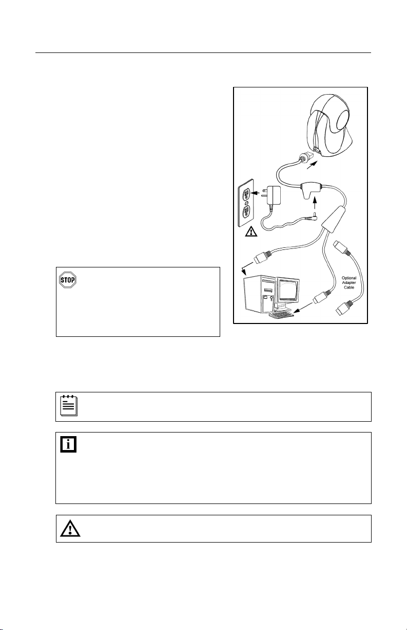
Keyboard Wedge
1. Turn off the host device.
2.
Plug the male 10-pin RJ45 end of the
PowerLink cable into the 10-pin
socket on the MS7120.
3. Disconnect the keyboard from the
host device.
4. Connect the “Y” end of the PowerLink
cable to the keyboard and the
keyboard port on the host PC. If
necessary use the male/female
adapter cable supplied with the
scanner for proper connections.
5. Plug the external power supply into the
power jack on the PowerLink cable.
Check the AC input requirements
of the power supply to make sure
the voltage matches the AC
outlet. The outlet must be
located near the equipment and
be easily accessible.
6. Connect AC power to the transformer.
7. Turn on the host device.
When the scanner first receives power, the blue and white LED will
toggle on and off then the scanner will beep once.
Powering the MS7120 directly from the host device can sometimes
cause interference with the operation of the scanner or the computer.
Not all computers supply the same current through the keyboard port.
For this reason, Honeywell recommends using an external power
supply. For additional information contact a customer service
representative.
Figure 11.
See page 5.
9
INSTALLATION
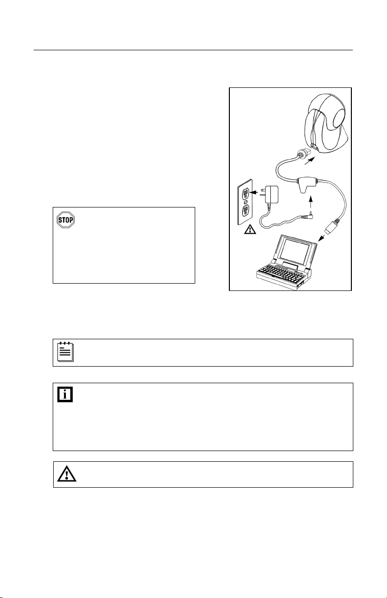
Stand-Alone Keyboard
1. Turn off the host device.
2.
Plug the male 10-pin RJ45 end
of the PowerLink cable into the
10-pin socket on the MS7120.
3. Connect the other end of the
PowerLink cable to the keyboard
port on the host device.
4. Plug the external power supply into
the power jack on the PowerLink
cable.
Check the AC input
requirements of the power
supply to make sure the
voltage matches the AC
outlet. The outlet must be
located near the equipment
and be easily accessible.
5. Connect AC power to the transformer.
6.
Turn on the host device.
When the scanner first receives power, the blue and white LED will
toggle on and off then the scanner will beep once.
Figure 12.
Powering the MS7120 directly from the host device can sometimes
cause interference with the operation of the scanner or the computer.
Not all computers supply the same current through the keyboard port.
For this reason, Honeywell recommends using an external power
supply. For additional information contact a customer service
representative.
ge 5.
See pa
10
 Loading...