

Page 1

MS4980
Area Imaging Scanner
Installation and User's Guide
Page 2

Disclaimer
Honeywell International Inc. (“HII”) reserves the right to make changes in
specifications and other information contained in this document without prior
notice, and the reader should in all cases consult HII to determine whether any
such changes have been made. The information in this publication does not
represent a commitment on the part of HII.
HII shall not be liable for technical or editorial errors or omissions contained
herein: nor for incidental or consequential damages resulting from the furnishing,
performance, or use of this manual.
This document contains propriety information that is protected by copyright. All
rights reserved. No part of this document may be photocopied, reproduced, or
translated into another language without the prior written consent of HII.
© 2008 – 2011 Honeywell International Inc. All rights reserved.
Web Address: www.honeywellaidc.com
Trademarks
Metrologic, MetroSelect, MetroSet2 and TotalFreedom are trademarks or
registered trademarks of Metrologic Instruments, Inc. or Honeywell International
Inc.
Microsoft, Windows, and Windows 95 are trademarks or registered trademarks of
Microsoft Corporation.
Other product names mentioned in this manual may be trademarks or registered
trademarks of their respective companies and are the property of their respective
owners.
Page 3

iii
Table of Contents
Introduction
Product Overview ............................................................................................. 1
Base Kit ............................................................................................................ 2
Optional Accessories ........................................................................................ 2
Scanner Components ....................................................................................... 3
Maintenance ..................................................................................................... 3
Cable Installation .............................................................................................. 4
Cable Removal ................................................................................................. 4
Labels ............................................................................................................... 5
Installation
RS232 .............................................................................................................. 7
Keyboard Wedge .............................................................................................. 8
USB (Powered by the Host Device) ................................................................. 9
USB (Powered by External Power Supply) ..................................................... 10
Mounting Specifications ................................................................................. 11
Mounting General Guidelines ......................................................................... 12
Operation
Modes of Operation ........................................................................................ 13
Audible Indicators ........................................................................................... 15
Visual Indicators ............................................................................................. 16
Failure Modes ................................................................................................. 17
Field of View ................................................................................................... 18
Depth of Field ................................................................................................. 19
IR Activation Range ........................................................................................ 20
Troubleshooting Guide .................................................................................... 21
Design Specifications
Operational ..................................................................................................... 25
Mechanical ..................................................................................................... 25
Electrical ......................................................................................................... 26
Environmental ................................................................................................ 26
Page 4

iv
Applications and Protocols ............................................................................. 27
Configuration and Upgrades
Configuration Modes ...................................................................................... 29
Upgrading the Firmware ................................................................................. 30
Scanner and Cable Terminations
Scanner Pinout ............................................................................................... 31
Cable Connector Configurations .................................................................... 33
Limited Warranty .............................................................................................. 35
Regulatory Compliance
Safety ............................................................................................................. 37
EMC ............................................................................................................... 38
Patents .............................................................................................................. 41
Index .................................................................................................................. 43
Customer Support ............................................................................................ 45
Technical Assistance ...................................................................................... 45
Product Service and Repair ............................................................................ 46
Page 5

1
Introduction
Product Overview
The MS4980 is a high performance area imaging bar code scanner packed into a
small yet rugged form factor. The scanner features a high-resolution CMOS
imaging sensor to deliver excellent omnidirectional 1D, PDF417 and 2D bar code
scan performance, optical character recognition (OCR) and image capture. Built
with small size in mind, the MS4980 includes important features for everyday
scanning operation such as:
IR object detection or manual button activation
High density bar code scanning with a large depth of field
Aggressive mobile phone & LCD scanning
Integrated mounting points
Rugged interface cable connection
Automatic detection and configuration for RS232, USB and Keyboard
Wedge interfaces
Honeywell adds value and functionality to the MS4980 by incorporating our
Flexible Licensing Solution and TotalFreedom™ platform, ensuring that the
product easily aligns the customer’s current and future scanning needs.
Model Interface
Interfaces supported include:
• RS232
MS4980 - 124
Configurable for Keyboard Emulation Mode or Serial Emulation Mode. The default
setting is Keyboard Emulation Mode.
• Keyboard Wedge
• USB
Note: Standard models ship with the ability to read all 1D, PDF and 2D bar
codes. Decoding and functional capability is limited and units will not
support key features including, but not limited to, the ability to decode
PDF, 2D or OCR fonts without proper limited use licenses provided by
Honeywell. If you wish to purchase a limited license for one or more of
the key features not included in the standard unit, please specify at the
time of sale or otherwise contact a customer service representative for
more information.
Page 6
2
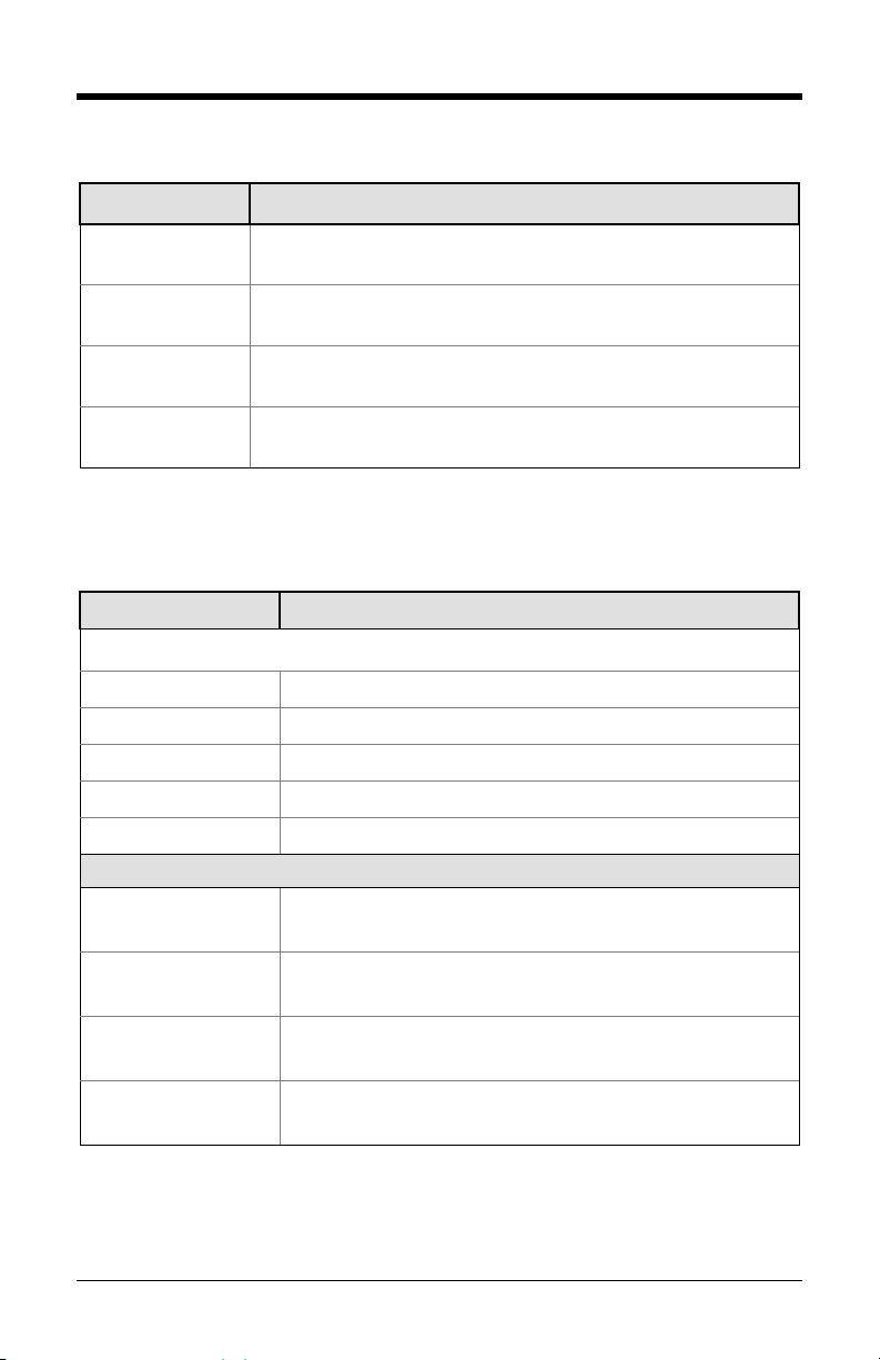
Basic Kit
Part # Description
MS4980 Area Imaging Bar Code Scanner
00-02544 MetroSelect® Single-Line Configuration Guide*
00-05252
70-79037 MS4980 Scanner Installation and User’s Guide*
*Available for download from www.honeywellaidc.com
Area Imaging Bar Code Scanner
Supplemental Configuration Guide*
Optional Accessories
Part # Description
AC to DC Power Transformer – Regulated 5.2VDC @ 1A output.
46-00525 120V United States
46-00526 220V-240V Continental European
46-00870 220V-240V United Kingdom
46-00528 220V-240V Australia
46-00529 220V-240V China
Communication Cable
52-52557x-3-FR RS232 straight PowerLink cable, with ferrite, black
52-52558x-3-FR
Keyboard Wedge straight PowerLink cable, with ferrite,
black
52-52559x-N-3-FR USB direct cable, with ferrite, black
52-52559x-3-FR USB straight PowerLink cable, with ferrite, black
Other items may be ordered for the specific protocol being used. To order additional items,
contact the dealer, distributor, or contact a customer service representative
Page 7
3
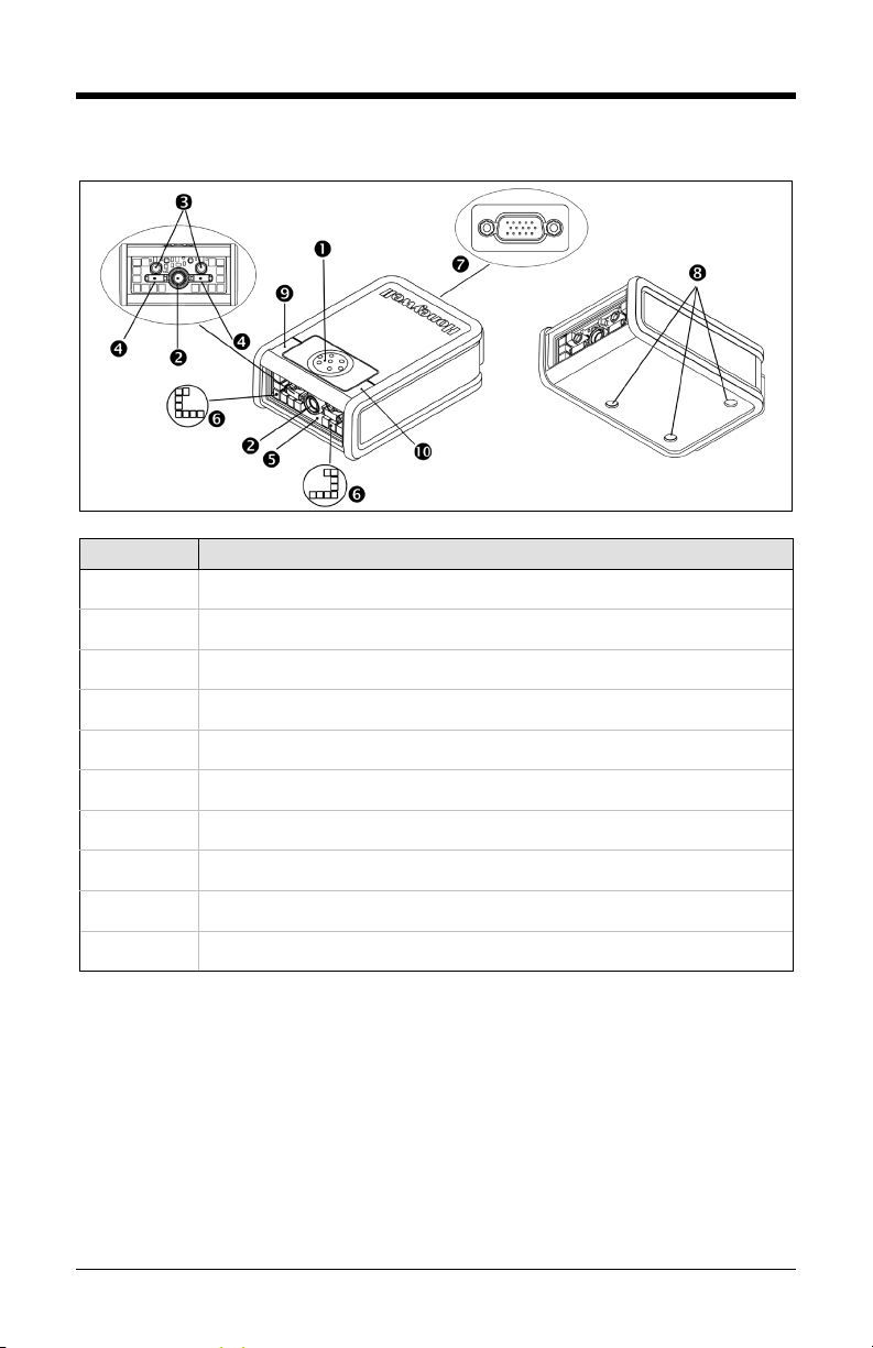
Scanner Components
Figure 1. Scanner Components
Item No. Description
Button
Camera Imager
Infrared Sensor (IR)
Targeting
Window
Area Illumination
Cable Connection (15-pin HD-22 D-type connector)
M3 Mounting Holes
White LED
Blue LED
Maintenance
Smudges and dirt on the unit’s window can interfere with the unit’s performance.
If the window requires cleaning, use only a mild glass cleaner containing no
ammonia. When cleaning the window, spray the cleaner onto a lint free, nonabrasive cleaning cloth then gently wipe the window clean.
If the unit’s case requires cleaning, use a mild cleaning agent that does not
contain strong oxidizing chemicals. Strong cleaning agents may discolor or
damage the unit’s exterior.
Page 8
4
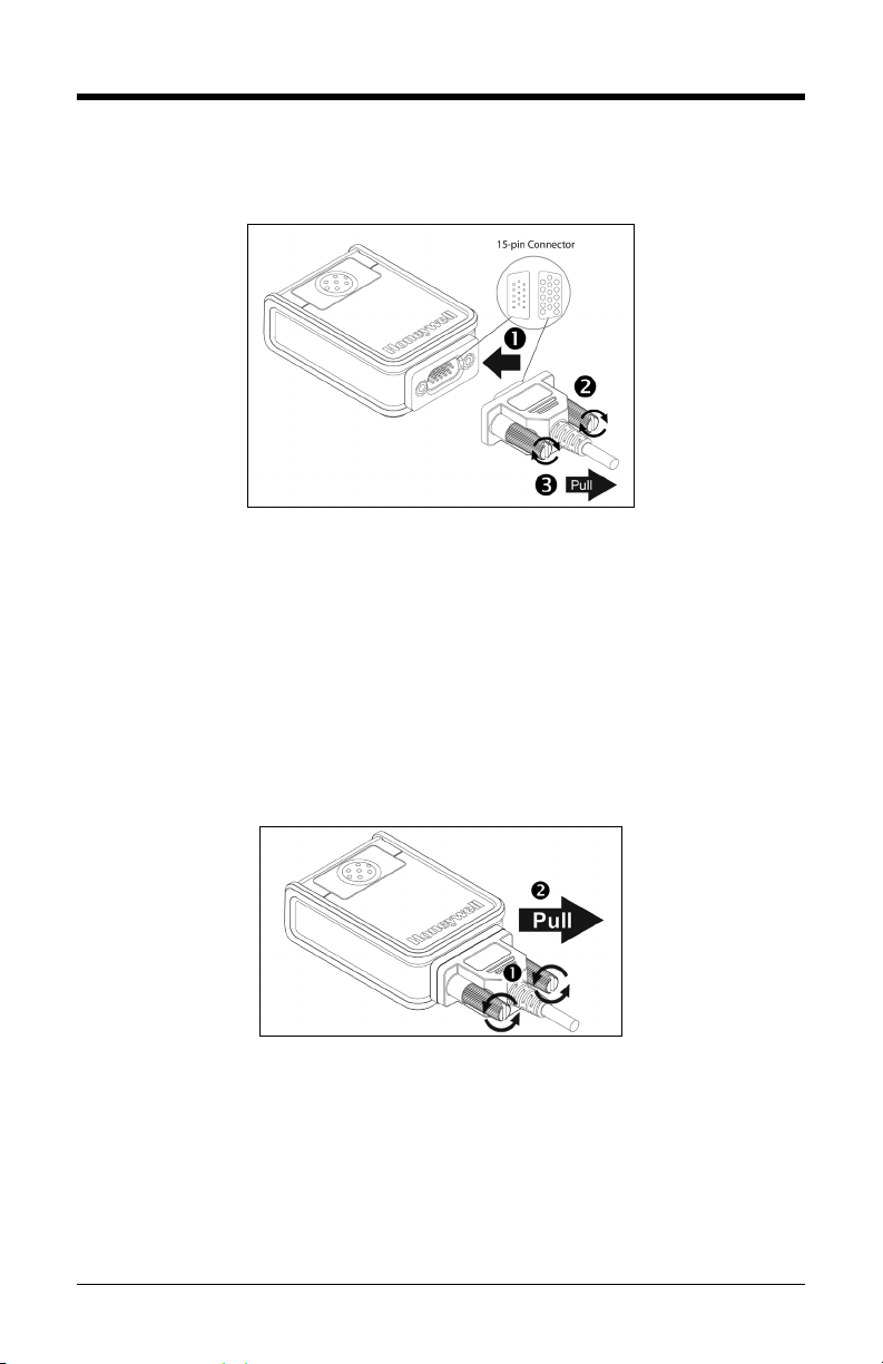
Cable Installation
Important: If the cable is not fully attached, the unit may power intermittently.
Figure 2. Cable Installation
1. Insert the 15-pin D-type connector end of the cable into the socket on the
MS4980.
2. Rotate the two screws clockwise to tighten.
3. Gently pull on the cable strain relief to insure the cable is installed.
Cable Removal
Before removing the cable from the scanner, turn off power on the host system
and disconnect the power supply, if applicable.
Figure 3. Cable Removal
1. Rotate the two screws counter clockwise to loosen the screws.
2. Pull gently on the strain-relief of the cable to remove it from the scanner.
Page 9
5
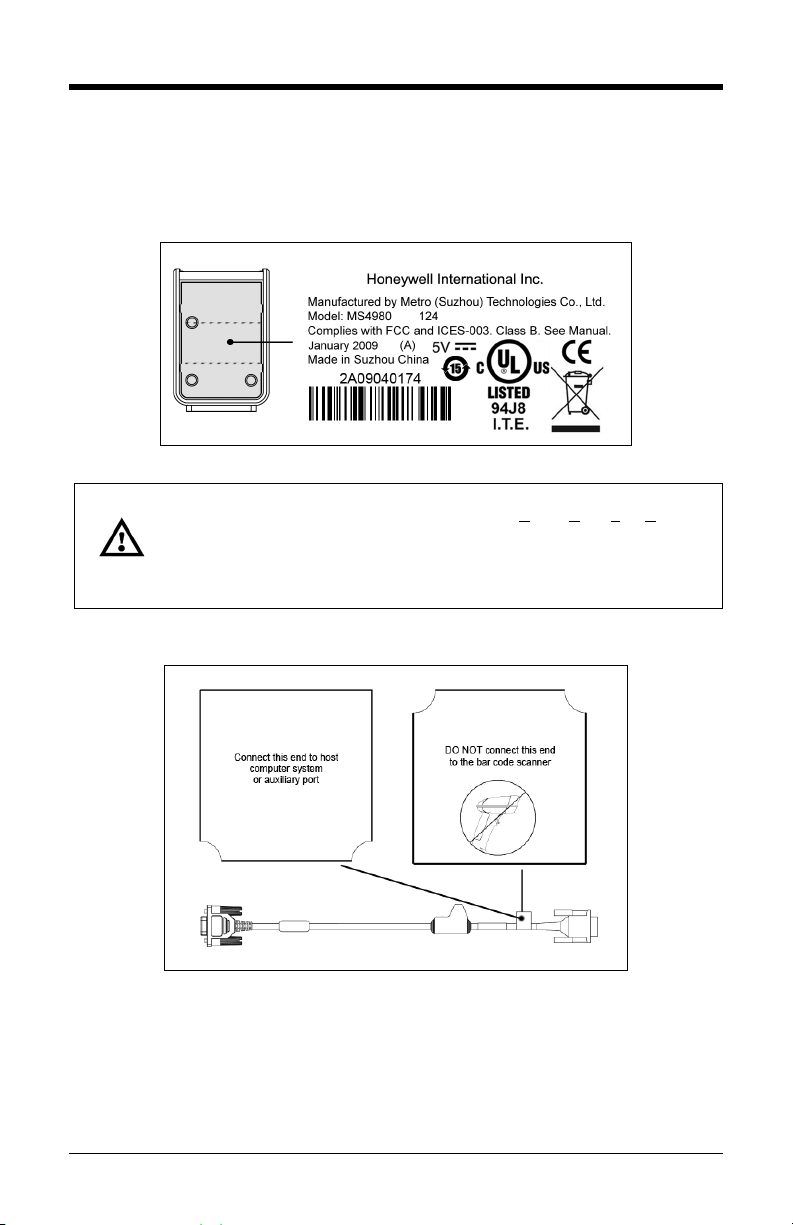
Labels
Every scanner has a label located on the underside of the unit. The label
contains important information such as the unit’s date of manufacture, serial
number, CE and caution information. Figure 4 provides an example of the label.
Caution: To maintain compliance with applicable standards, all circuits connected to
To maintain compliance with standard CSA C22.2 No. 60950-1/UL 60950-1
the imager must meet the requirements for SELV (Safety Extra Low Voltage)
according to EN/IEC 60950-1.
and norm EN/IEC 60950-1, the power source should meet applicable
performance requirements for a limited power source.
Figure 4 . Label Example
RS232 Cable Label
Figure 5. RS232 Cable Label
Page 10

6
Page 11

7
Installation
RS232
1. Turn off the host device.
2. Plug the 15-pin socket end of the
cable into the 15-pin D-Type
connector on the MS4980
(see page 4).
3. Connect the 9-pin D-type connector
of the communication cable to the
proper COM port of the host device.
4. Plug the power supply into the power
jack on the PowerLink cable.
5. Check the AC input requirements of
the power supply to verify the
voltage matches the AC outlet. The
outlet must be located near the
equipment and be easily accessible.
6. Connect AC power to the
transformer.
7. The MS4980 will start to initialize. The white and blue LED will alternately
fade on and off for approximately three seconds. When the scanner has
finished initializing, the unit will flash the white LED three times while
simultaneously beeping three times. The low intensity blue LED will remain
turned on.
8. Turn on the host device.
Figure 6.
Installation Note
Plugging the scanner into a port on the host system does not guarantee that
scanned information will be communicated properly to the host system. Please
refer to the MetroSelect Single-Line Configuration Guide or MetroSet2’s help files
for instructions on changing the scanner’s factory default configuration. The
scanner and host system must use the same communication protocols.
See caution on page 5
.
Page 12

8
Keyboard Wedge
1. Turn off the host device.
2. Plug the 15-pin socket end of the
cable into the 15-pin D-Type
connector on the MS4980 (see
page 4).
3. Disconnect the keyboard from the
host device.
4. Connect the “Y” ends of the
communication cable to the
keyboard and keyboard port on the
host device. If necessary, use the
male/female adapter cable supplied
with the scanner for proper
connections.
5. Plug the power supply into the power
jack on the PowerLink cable.
6. Check the AC input requirements of
the power supply to verify the
voltage matches the AC outlet. The
outlet must be located near the
equipment and be easily accessible.
Figure 7.
7. Connect AC power to the transformer.
8. The MS4980 will start to initialize. The white and blue LED will alternately
fade on and off for approximately three seconds. When the scanner has
finished initializing, the unit will flash the white LED three times while
simultaneously beeping three times. The low intensity blue LED will remain
turned on.
9. Turn on the host device. The scanner will automatically reboot after host
device is turned on.
Important Note
Plugging the scanner into a port on the host system does not guarantee that
scanned information will be communicated properly to the host system. Please
refer to the MetroSelect Single-Line Configuration Guide or MetroSet2’s help files
for instructions on changing the scanner’s factory default configuration. The
scanner and host system must use the same communication protocols.
See caution on page 5.
Page 13

9
USB (Powered by the Host Device)
1. Turn off the host device.
2. Plug the 15-pin socket end of the USB
cable into the 15-pin D-Type
connector on the MS4980
(see page 4).
3. Plug the USB end of the cable into the
host’s USB port.
4. Turn on the host device.
5. The MS4980 will start to initialize.
The white and blue LED will
alternately fade on and off for
approximately three seconds. When
the scanner has finished initializing,
the unit will flash the white LED three
times while simultaneously beeping
three times. The low intensity blue
LED will remain turned on. The
scanner will automatically reboot after
first initialization.
Figure 8.
Installation Note
Plugging the scanner into a port on the host system does not guarantee that
scanned information will be communicated properly to the host system. Please
refer to the MetroSelect Single-Line Configuration Guide or MetroSet2’s help files
for instructions on changing the scanner’s factory default configuration. The
scanner and host system must use the same communication protocols.
See caution on page 5.
Page 14

10
Figure 9.
USB (Powered by External Power Supply)
1. Turn off the host device.
2. Plug the 15-pin socket end of the
cable into the 15-pin D-Type
connector on the MS4980
(see page 4).
3. Plug the USB end of the cable into
the host’s USB port.
4. Plug the power supply into the power
jack on the PowerLink cable.
5. Check the AC input requirements of
the power supply to verify the
voltage matches the AC outlet.
The outlet must be located near the
equipment and be easily accessible.
6. Connect AC power to the
transformer.
7. The MS4980 will start to initialize.
The white and blue LED will
alternately fade on and off for
approximately three seconds. When
the scanner has finished initializing,
the unit will flash the white LED three
times while simultaneously beeping
three times. The low intensity blue
LED will remain turned on.
8. Turn on the host device. The scanner will automatically reboot after host
device is turned on.
Installation Note
Plugging the scanner into a port on the host system does not guarantee that
scanned information will be communicated properly to the host system. Please
refer to the MetroSelect Single-Line Configuration Guide or MetroSet2’s help files
for instructions on changing the scanner’s factory default configuration. The
scanner and host system must use the same communication protocols.
See caution on page 5.
Page 15

11
Mounting Specifications
The MS4980 has three M3 x 0.5 mm threaded inserts on the bottom of the
scanner for mounting with screws.
Figure 10.
Page 16

12
Mounting General Guidelines
• Avoid specular reflections, caused by ambient and internal light
sources.
• The bar code should be slightly off perpendicular to the axis of the
scanner.
• To reduce specular reflections the skew angle can vary significantly
depending on the application such as: ambient illumination sources,
code size and code type.
• Excessive angles should be avoided.
• Other factors, such as surface qualities, mounting distances, secondary
windows and external illumination can easily impact these
recommendations.
• If a secondary window is used, the window should be mounted as close
to the front of scanner as possible at a 90° angle to the optical axis to
avoid specular reflections.
• For secondary windows, Honeywell recommends the following:
o Optical quality glass
o >95% transmission in the nominal 650nm wavelength
o Anti-reflective coating on both sides
• A skew angle of 15° to 20° between the normal of the bar code’s
surface and the optical axis of the imager is sufficient to avoid specular
reflections.
• Avoid pitch angles above 15° to 20° to prevent code compression.
Figure 11.
Page 17

13
Operation
Modes of Operation
The MS4980 supports two standard modes of operation for scanning bar codes,
automatic activation and manual activation scanning. Scanning while in the
automatic activation mode can occur in either one of two configurable options,
pass-through
options are enabled by default.
operates in the pass-through state for 300 ms and then changes to the
presentation state for additional decoding capability.
Automatic Activation Mode
Pass-through Scanning - Decodes ONLY 1D and PDF bar codes
Scanning Method:
1. Pass the bar code through the active scan area to scan, decode and
Presentation Scanning - Decodes ALL 1D, PDF and 2D matrix codes
Scanning Method:
1. Place the object in the IR activation range
2. Hold the object’s bar code in front of the scan window within the active
The MS4980 requires a stand-alone 5V power supply for pass-through capabilities to
function.
Default configuration recommended for optimum scan performance.
or presentation. Both the pass-through and the presentation
With the default configuration, the scanner
send data
scan area to scan, decode and send data
Page 18

14
Manual Activation
Decodes ALL 1D, PDF and 2D matrix codes
Scanning Method:
1. Press the button one time to activate linear targeting.
2. Align the linear targeting line over the desired bar code.
Note: When scanning 1D programming bar codes, the bar code must
be presented to the scanner in the correct orientation, see
Figure 12. PDF and 2D matrix codes may be presented in any
orientation.
Figure 12. 1D Programming Bar Code Orientation
3. Press the button a second time to decode and send the data.
4. The unit will return to the default presentation mode either by the default
time length or by double clicking the button.
Note: Decoding and functional capability of the unit is restricted through the use
of license numbers provided by Honeywell. Units will not support key
features such as, but not limited to, the ability to decode PDF, 2D or OCR
fonts without the proper licenses. Desired licenses can be specified at the
time of sale or call a customer service representative for more information.
Standard models ship with the ability to read all 1D, PDF and 2D bar
codes. OCR fonts are disabled by default and must be specifically
requested at an additional cost.
Scanner configuration bar codes require the manual activation mode.
2D matrix bar code types are not enabled by default in the manual activation mode.
Refer to the Area-Imaging Supplemental Configuration Guide (see page 2) for
additional information on enabling code types.
Page 19

15
Audible Indicators
When the MS4980 is in operation, it provides audible feedback. These sounds
indicate the status of the scanner. Eight settings are available for the tone of the
beep (normal, six alternate tones and no tone). To change the tone, refer to the
MetroSelect Single-Line Configuration Guide, PN 00-02544, or MetroSet2’s help
files.
One Beep
When the scanner successfully reads a bar code the unit will beep once and the
white LED will flash once indicating data has been transmitted successfully. The
blue LED will return to the low intensity state if no other objects are presented in
the active scan area.
If the scanner does not beep once and the white light does not flash, then the bar
code has not been successfully read.
Short Razzberry Tone
This tone is a failure indicator (see Failure Modes on page 17).
Long Razzberry Tone
This tone is a failure indicator (see Failure Modes on page 17).
Three Beeps – At Power Up
When the MS4980 first receives power, it will start an initialization sequence.
The white and blue LEDs will alternately fade on and off for approximately three
seconds. When the scanner has finished initializing the white LED will flash
three times while simultaneously beeping three times to indicate the scanner is
ready for use.
Three Beeps – Configuration Mode
When entering configuration mode, the white LED will flash while the scanner
simultaneously beeps three times. The white and blue LEDs will continue to
flash while in this mode. Upon exiting configuration mode, the scanner will beep
three times, and the LEDs will stop flashing.
When configured, three beeps can also indicate a communications timeout
during normal scanning mode.
When using single-code-configuring, the scanner will beep three times: a normal
tone followed by a short pause, a high tone and then a low tone. This indicates
that the single configuration bar code has successfully configured the scanner.
Page 20

16
Visual Indicators
The scanner has blue and white LED
indicators on either side of the button on the
top of the unit. When the scanner is on, the
intensity of the LED and the flashing or
stationary activity of the LEDs, indicates the
status of the current scan and the diagnostic
scanner.
Figure 13.
No LEDs are Illuminated
The LEDs will not be illuminated if the scanner is not receiving power from the
host or transformer.
Steady Low Intensity Blue
The scanner is in stand-by mode. Present a bar code to the scanner and the
blue LED will switch to a high intensity blue when the IR detects the object.
Steady High Intensity Blue
The high intensity blue LED is illuminated when the scanner is active and
attempting to decode a bar code.
Single White Flash
When the scanner successfully reads a bar code the unit will beep once and the
white LED will flash once indicating data has been transmitted successfully. The
blue LED will return to the low intensity state if no other objects are presented in
the active scan area.
If the scanner does not beep once and the white light does not flash, then the bar
code has not been successfully read.
Steady White
When the scanner successfully reads a bar code, it will beep once and the white
LED will turn on indicating data is being transmitted.
Note: After a successful scan, the scanner transmits the data to the host device.
Some communication modes require that the host inform the scanner
when data is ready to be received. If the host is not ready to accept the
information, the scanner’s white LED will remain on until the data can be
transmitted.
Alternating Flashing of Blue and White
This indicates the scanner is in configuration mode. A short razzberry tone
indicates that an invalid bar code has been scanned while in this mode.
Page 21

17
Failure Modes
Long Razzberry Tone – During Power Up
Failed to initialize or configure the scanner. If the scanner does not respond after
reconfiguration, return the scanner for repair.
Short Razzberry Tone – During Scanning
An Invalid bar code has been scanned when in configuration mode.
Page 22

18
Field of View
Figure 14. MS4980 Field of View
Specifications are subject to can without notice.
Page 23

19
Depth of Field
Minimum Bar Code Element Width
mm .132 .190 .264 .330 .190 .381
mils 5.2 7.5 10.4 13 7.5 15
Note: Standard models ship with the ability to read all 1D, PDF and 2D bar
Specifications are subject to can without notice.
A B C D E F
codes. Decoding and functional capability is limited and units will not
support key features including, but not limited to, the ability to decode
PDF, 2D or OCR fonts without proper limited use licenses provided by
Honeywell. If you wish to purchase a limited license for one or more of the
key features not included in the standard unit, please specify at the time of
sale or otherwise contact a customer service representative for more
information.
1D
Figure 15. Depth of Field
PDF
Page 24

20
IR Activation Range
The MS4980 scanner has a built in object detection sensor that instantly turns on
the scanner when an object is presented within the scanner’s IR activation area.
Figure 16. IR Activation Area
Specifications are subject to can without notice.
Page 25

21
Troubleshooting Guide
The following guide is for reference purposes only. Contact a customer service
representative to preserve the limited warranty terms, see page 45.
All Interfaces
Symptoms Possible Causes Solution
Check transformer, outlet and
No power is being
supplied to the scanner.
No LEDs, beep
or illumination.
No power is being
supplied to the scanner
from the host.
power strip. Make sure the
cable is plugged into the
scanner.
Some host systems cannot
supply enough current to
power the MS4980. A power
supply may be required.
Long Razz tone
on power up.
Long Razz tone
when exiting
configuration
mode.
Long Razz tone.
Short Razz tone
in configuration
mode.
There has been a
scanner configuration
failure.
There has been a
diagnostic failure.
There was a failure
saving the new
configuration.
There was a scanning
mechanism failure.
An invalid bar code has
been scanned.
Contact a customer service
representative if the unit will
not hold the saved
configuration.
Contact a customer service
representative if the unit will
not function.
Re-try to configure the scanner.
Contact a customer service
representative if the unit will not
hold the saved configuration.
Contact a customer service
representative.
Scan a valid bar code or quit
configuration mode.
Page 26

22
scanned falls into the configured
Symptoms Possible Causes Solution
The unit powers
up, but does not
beep when bar
code is scanned.
The unit powers
up, but does not
scan and/or
beep.
The beeper is disabled
and no tone is selected.
The bar code symbology
trying to be scanned is
not enabled.
Enable the beeper and select
a tone.
UPC/EAN, Code 39,
interleaved 2 of 5, Code 93,
Code 128, Codabar and PDF
are enabled by default. Verify
that the type of bar code being
read has been selected.
The unit powers
up, but does not
scan and/or
beep.
The following item is only relevant for RS232 and Serial USB Interfaces.
The unit scans
a bar code, but
locks up after
the first scan
and the white
LED stays on.
The unit scans,
but the data
transmitted to
the host is
incorrect.
The scanner is trying
to scan a bar code that
does not match the
configured criteria.
The scanner is configured
to support some form of
host handshaking but is
not receiving the signal.
The scanner’s data
format does not match
the host system
requirements.
Verify that the bar code being
criteria (i.e. character length
lock or minimum bar code
length settings).
If the scanner is setup to
support ACK/NAK, RTS/CTS,
or XON/XOFF, verify that the
host cable and host are
supporting the handshaking
properly.
Verify that the scanner’s data
format matches that required
by the host. Make sure that
the scanner is connected to
the proper host port.
Page 27

23
Symptoms Possible Causes Solution
The bar code may have
been printed incorrectly.
The unit beeps
at some bar
codes and NOT
for others of the
same bar code
symbology.
The unit scans
the bar code but
there is no data.
The next four items are only relevant for a Keyboard Wedge interface.
The unit scans
but the data is
not correct.
The unit is
transmitting
each character
twice.
The scanner is not
configured correctly for
this type of bar code.
The minimum symbol
length setting does not
work with the bar code.
The configuration is not
set correctly.
The configuration is not
set correctly.
The configuration is not
set correctly.
Check if it is a check
digit/character/or border
problem.
Check if check digits are set
properly.
Check if the correct minimum
symbol length is set.
Make sure the scanner is
configured for the appropriate
mode.
Make sure that the proper PC
type AT or PS2 is selected.
Verify correct country code
and data formatting are
selected. Adjust inter-character
delay symptom.
Increase interscan code delay
setting. Adjust whether the F0
break is transmitted. It may be
necessary to try this in both
settings.
Alpha
characters show
as lower case.
Everything
works except for
a couple of
characters.
The computer is in Caps
Lock mode.
These characters may
not be supported by that
country’s key look up
table.
Enable Caps Lock detect
setting of the scanner to detect
if the PC is operating in Caps
Lock.
Try operating the scanner in
Alt mode.
Page 28

24
The USB host may not be
sufficient power to support
Symptoms Possible Causes Solution
The unit scans
but the data is
not correct.
The scanner and host
may not be configured for
the same interface
parameters.
Check that the scanner and the
host are configured for the
same interface parameters.
The following item is only relevant for an RS232 interface.
The unit powers
up OK and scans
OK but does not
communicate
properly with the
host.
The com port at the host
is not working or not
configured properly.
Check to make sure that the
baud rate and parity of the
scanner and the
communication port match and
the program is looking for
“RS232” data.
The unit powers
up OK and scans
OK but does not
communicate
properly with the
The cable is not
connected to the correct
COM port.
Check to make sure that the
cable is connected to the
correct COM port.
host.
Add some inter-character delay
to the transmitted output by
using the Configuration Guides
(PN 00-02544 and 00-05252).
Characters are
being dropped.
Inter-character delay
needs to be added to the
transmitted output.
The following item is only relevant for a USB interface.
No LEDs, beep
or illumination.
active.
The MS4980 will not
operate from hub/host
power without host
communication.
The unit is not receiving
operation.
Refer to the electrical
specifications on page 26.
Turn on the host device.
Verify adequate power is being
supplied to the scanner.
Page 29

25
Design Specifications
Operational
Light Source: LED 645 nm ± 7.5 nm
Pulse Duration: Up to 4 mS (Default)
Maximum Output of LED: 2.63 mW
Depth of Scan Field: 40 mm – 300 mm (1.57" – 11.8") for 0.33 mm (13 mil)
40 mm x 30 mm (1.57" x 1.18") @ 40mm (1.57") from Face
Field of View:
Minimum Element Width:
Resolution: 1280 x 960 Pixels
Infrared Activation Range: 0 mm (0") face to 254 mm (10")
Optional Decode and
Imaging Capabilities:
System Interfaces: Keyboard Wedge, RS232, USB
Print Contrast: 20% Minimum Reflectance Difference
Number Characters Read: 4096 Bytes Maximum
Beeper Operation: 7 tones or no beep
Indicators (LED)
Default Settings:
250 mm x 187.5 mm (9.84" x 7.38") @ 300 mm (11.8") from
Face
1D 0.127 mm (5 mil)
2D 0.19 mm (7.5 mil)
Autodiscriminates all Standard 1-D, GS1 DataBar,
PDF417, microPDF, MaxiCode, Data Matrix, QR Code,
UCC, EAN Composites, Postals, Aztec
(Image Transfer) – BMP, TIFF, or JPEG output on USB
and RS232 Interfaces
High Intensity Blue
Low Intensity Blue The unit is idle
White Good Read
The unit is active and attempting to
scan
Mechanical
Depth (D): 74 mm (2.91")
Width (W): 50 mm (1.97")
Height (H): 26 mm (1.02")
Weight: 70 g (2.5 oz.)
Specifications are subject to change without notice.
Page 30

26
Electrical
Input Voltage: 5.2 VDC ± 0.25V
RS232,
USB w/Power Jack,
Keyboard Wedge
Peak
2.1 W (Typical) 1.9 W (Typical)
USB Host Powered
Power:
Current:
DC Transformers: Class II: 5.2VDC @ 1 A
For Regulatory Compliance Information see pages 37 – 40.
Operating 1.7 W (Typical) 1.7 W (Typical)
Idle 1.2 W (Typical) 1.2 W (Typical)
Peak
398 mA (Typical) 360 mA (Typical)
Operating 331 mA (Typical) 317 mA (Typical)
Idle 230 mA (Typical) 230 mA (Typical)
Peak Values of at least 1 ms in width.
Environmental
Operating = 0°C to 40° (32° to 104°F)
Temperature:
Storage = -20°C to 70°C (-4°F to 158°F)
Humidity: 5% to 95% relative humidity, non-condensing
Light Levels: Up to 100,000 Lux (9,290 footcandles)
Shock: Designed to withstand 1.5 m (5 ft.) drops
Contaminants: Sealed to resist airborne particulate contaminants
Ventilation: None required
Specifications are subject to change without notice.
Page 31

27
Version
Identifier
*USA
Italian
Swiss
Belgian
Japanese
Swedish/Finnish
French
Russian Cyrillic
Turkish
German
Slovenian
United Kingdom
Hungarian
Spanish
Applications and Protocols
The model number on each scanner includes the scanner number.
Scanner
Interfaces supported include:
MS4980 124
USB is configurable for Keyboard Emulation Mode, Bi-Directional Serial Emulation
Mode or IBM OEM. The default USB setting is Keyboard Emulation Mode.
The following are the most important selectable options specific to the keyboard
wedge.
• *AT (includes IBM
• IBM PS2 (includes models 30, 70, 8556)
Keyboard Country Type
•
•
•
•
•
* Indicates a default setting. For information on how to change the default
settings, refer to the help files in MetroSet2, the MetroSelect Single-Line
Configuration Guide or the Area Imaging Supplemental Configuration Guide.
•
•
•
•
•
Communication Protocol(s)
• RS232 (TXD, RXD, RTS, CTS)
• Keyboard Wedge
• USB
Keyboard Type
®
PS2 models 50, 55, 60, 80)
•
•
•
•
Page 32

28
Page 33

29
Configuration and Upgrades
Configuration Modes
The MS4980 has three modes of configuration.
• Bar Codes
The MS4980 can be configured by scanning the bar codes included in the
MetroSelect Single-Line Configuration Guide or the Area Imaging
Supplemental Configuration Guide shipped with the area imager. The
manuals are available for download at www.honeywellaidc.com.
• MetroSet2
This user-friendly Windows-based configuration program allows you to
simply ‘point-and-click’ at the desired scanner options. MetroSet2 is
available for download at www.honeywellaidc.com.
• Serial Programming
This mode of configuration is ideal for OEM applications. This mode gives
the end-user the ability to send a series of commands using the serial port of
the host system. The commands are equivalent to the numerical values of
the bar codes located in the MetroSelect Single-Line Configuration Guide.
 Loading...