

Page 1

Dampers, Actuators and Valves
control your environment with honeywell
DAmPerS, vAlveS AnD ActuAtorS
Application And Selection Guide
Page 2

How to use this guide
All pages in this literature are constructed in one of two ways:
For unassembled product:
As a reference, pictures will represent the valves and actuators
separately; and part numbers are highlighted in blue. To order a
complete product one OS# must be chosen from each blue box.
For factory assembled product:
The complete assembled OS# will be displayed in the body of
the chart (except for cartridge cage valves, both an actuator and
valve must be chosen). Pictures will also reference the factory
assembled configuration.
Additional product information
To find more detailed information on the individual products
included in this document, go to: http://customer.honeywell.com
and use the search text box to quickly locate product specific
content.
SUPPORT
Contact Information Phone Fax
Commercial Components
Technical Hotline 888-516-9347
Customer Care
Order Entry 888-793-8193 800-356-0149
Product Drop-Ship Team 763-954-4140 800-356-0149
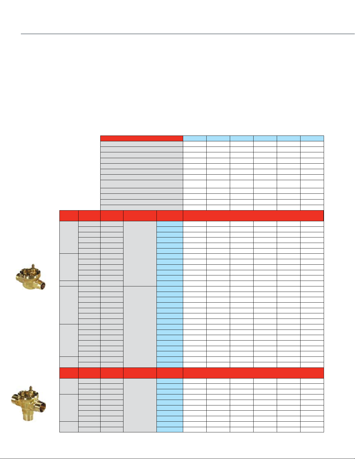
Butterfly & Flanged Control Ball Valve Ordering
Take-Off Service 888-664-4092 877-880-3386
Let Honeywell Take-Off Service provide a complete
job schedule for your projects for dampers, actuators,
valves and VFDs.
Online Resources
Honeywell Customer Web Site http://customer.honeywell.com
A web site with a large amount of information,
literature, pricing, and product selection tools
that is available to you at any time.
Honeywell Consulting Engineer Web Site http://specifyhoneywell.com
A website developed for consulting engineers. Get
product guide specs, wiring diagrams and more.
Honeywell eLearning http://customer.honeywell.com/learning
A convenient and smart way of learning about our
products with 10 to 20 minute training modules.
Register at the Honeywell customer website above for access.
Page 3

TABLE OF CONTENTS
Section 1: DCA & Damper Selection
Dampers ......................................................................................8
DCA ...........................................................................................12
Fire and Smoke ..........................................................................14
Section 2: Valve Selection
Control Valve Applications .........................................................17
Control Valve Selection Criteria ..................................................18
2-Way ...................................................................................18
3-Way ...................................................................................20
Fan Coil and Zone Valves .......................................................... 22
Cartridge Cage Valves ................................................................24
Cartridge Globe Valves ...............................................................26
Control Ball Valves ½ - 3”
2-Way NPT NEMA 2 .............................................................28
2-Way NPT NEMA 3R ...........................................................30
Control Ball Valves ½ - 2 ½”
3-Way NPT NEMA 2 .............................................................32
3-Way NPT NEMA 3R .......................................................... 33
Flanged Control Ball Valves 4”- 6”
2-Way Flanged NEMA 2+3R .................................................34
3-Way Flanged NEMA 2+3R .................................................35
NPT Globe Valves ½-3”
With Dedicated Valve Actuators ............................................36
With Direct Coupled Actuators..... .........................................38
Flanged Globe Valves 2 ½ -3”
With Direct Coupled Actuators ..............................................42
Threaded and Flanged Globe Valves 2”-3”
With Tandem Linked Direct Coupled Actuators ....................46
Flanged Globe Valves 2 ½ - 3”
With Dedicated Valve Actuators ............................................48
Flanged Globe Valves 4”-6”
With Tandem Linked Direct Coupled Actuators .....................52
With Dedicated Valve Actuators ............................................54
Flanged Cage Valves 2 ½ - 6” ....................................................55
NPT Globe Valves ½ -3”
With Pneumatic Actuators .....................................................56
Flanged Globe Valves 2 ½ - 3”
With Pneumatic Actuators .....................................................60
Flanged Globe Valves 4”- 6”
With Pneumatic Actuators .....................................................64
Resilient Seat Butterfly Valves
2-Way Electrically-Actuated Control ......................................66
3-Way Electrically-Actuated Control ......................................68
2-Way Pneumatically-Actuated Control .................................72
3-Way Pneumatically-Actuated Control .................................74
Section 3: Submittal Sheets
Rectangular Volume Control Dampers
D1 Series ............................................................................. 78
D2 and D3 Series ..................................................................79
Round Volume Control Dampers
D690 .....................................................................................80
DM7600 ................................................................................81
Spring Return Direct Coupled Actuator
S03 Series (MS4103; MS4603; MS7403; MS7503; MS8103) ...82
S05 Series (MS4105; MS4605; MS7105; MS7405; MS7505;
MS8105) ..................................................................83
S05 Series (MS4105; MS7505; MS8105) ..................................84
S10 Series (MS4110; MS7510; MS8110) ..................................85
S20 Series (MS4120; MS7520; MS8120) .................................86
ML4125; ML8125 ................................................................87
Non-Spring Return Direct Coupled Actuator
ML6161; ML7161 .................................................................88
ML6174; ML7174 .................................................................89
N05 Series (MN6105; MN7505) ............................................90
N10 Series (MN6110; MN7510) ............................................91
N20 Series (MN6120; MN7220) ............................................92
N34 Series (MN6134; MN7234) .................................................93
Fire And Smoke Actuators
ML4115; ML8115 ................................................................94
MS4209F; MS4309F; MS4709F; MS4809F; MS8209F;
MS8309F ..............................................................................95
MS4120F; MS4620F; MS8120F ...........................................96
Pneumatic Damper Actuator
MP909D ................................................................................97
MP909E, H ...........................................................................98
MP913 ..................................................................................99
MP918A, B .........................................................................100
MP920 ................................................................................101
Pneumatic Valve Actuator
MP953C, D .........................................................................102
MP953E, F ..........................................................................103
3
Page 4

TABLE OF CONTENTS
Section 3: Submittal Sheets (CONT.)
MP958 ................................................................................104
Modutrol IV Motor
M4185; M8185 ...................................................................105
M6184; M6194 ...................................................................106
M6285 for slaving applications ............................................107
M6284; M6294 for slaving applications ...............................108
M6274; M6284; M6285; M6294 Motors with
Linear 10K Feedback ..........................................................109
M7164 ...............................................................................110
M7274; M7284; M7285; M7286; M7294 ................................111
M9164; M9174; M9182; M9184; M9194 ...........................112
M9175; M9185; M9186 ......................................................113
Q7130; Q7230; Q7330 .......................................................114
Unitary Valve Actuator
VU443; VU444; VU843; VU844 ..........................................115
VC Series Two-position .......................................................116
VC Series Proportional ........................................................117
VC Series Fail Safe Proportional ..........................................118
M6410; M7410 ...................................................................119
M6435; M7435 ...................................................................120
Direct Coupled Valve Actuator
ML6420; ML7420 ...............................................................121
ML6421; ML7421 ...............................................................122
ML6425; ML7425 ...............................................................123
ML6984 .............................................................................124
ML7984 ..............................................................................125
Unitary Valve
VU52; VU53 ........................................................................126
VU54 ...................................................................................127
VCZA; VCZB .......................................................................128
VCZM; VCZN ......................................................................129
V5852; V5862 .....................................................................130
V5853; V5863 .....................................................................131
Control Ball Valve
VBN2 ..................................................................................132
VBN3 ..................................................................................133
VBF2 ...................................................................................134
VBF3 ...................................................................................135
NPT Globe Valve
V5011F, G ...........................................................................136
V5011N ...............................................................................137
V5013N ...............................................................................138
4
Flanged Cage Valve
V5051A ...............................................................................139
Flanged Globe Valve
V5011A, B ..........................................................................140
V5013B, C ..........................................................................141
VGF2 ...................................................................................142
VGF2 Pressure Balanced ....................................................143
VGF3 ...................................................................................144
Resilient Seat Butterfly Valves
VFF1 ...................................................................................145
VFF2 ...................................................................................146
VFF3 ...................................................................................147
VFF6 ...................................................................................148
Damper Linkage
Q605 ...................................................................................149
Valve Linkage
Q5001 .................................................................................150
Q5020 .................................................................................151
Q5022 .................................................................................152
Section 4: Wiring Diagrams
Actuator Wiring Diagrams .......................................................154
Section 5: Guide Specifications
Guide Specifications ..............................................................170
Section 6: Accessories
Ball Joints, Push Rod Accessories ...........................................186
Control, Positioning, Feedback Accessories ............................186
Mounting Accessories ..............................................................187
Rotational Limiters, Position Indicators .....................................188
Crankarms ...............................................................................189
Shaft Adaptor Accessories .......................................................189
Enclosure Accessories .............................................................190
Q7002 Interface Modules .........................................................190
Miscellaneous Accessories ......................................................190
Accessories for Obsolete Actuators .........................................191
Valve Actuator Accessories ......................................................192
VU Series Fan Coil Actuator Accessories .................................192
Pneumatic Damper Actuator Parts and Accessories ................193
Page 5

Pneumatic Valve Actuator Parts and Accessories ....................196
Foot Mounted Motor Accessories ............................................198
Damper and Valve Linkage Accessories ...................................200
Section 8: Competitive Cross Reference
Direct Coupled Actuator ...........................................................202
Control Ball Valve
2-Way Valve .......................................................................220
2-Way Valve + Non-Spring Return Floating Actuator ...........221
2-Way Valve + Non-Spring Return Modulating Actuator......222
2-Way Valve + Spring Return, 2-Position Actuator ..............223
2-Way Valve + Spring Return Floating Actuator ...................224
2-Way Valve + Spring Return Modulating Actuator .............225
Threaded Globe Valves ............................................................226
Flanged Globe Valves ...............................................................227
Pneumatics ..............................................................................228
Modutrol IV Motor ....................................................................231
TABLE OF CONTENTS
Section 8:
APPENDIX A:
Valve Selection & Sizing ...........................................................244
APPENDIX B:
NEMA Standard Classification Code for Enclosures ................263
APPENDIX C:
Best Practices for Low Power Control Signal Wiring ................264
Notes .......................................................................................265
Warranty...................................................................................267
5
Page 6

6
Page 7

SELECTION GUIDE
Section 1: DCA & Damper Selection
Dampers ......................................................................................8
DCA ...........................................................................................12
Fire and Smoke ..........................................................................14
7
Page 8
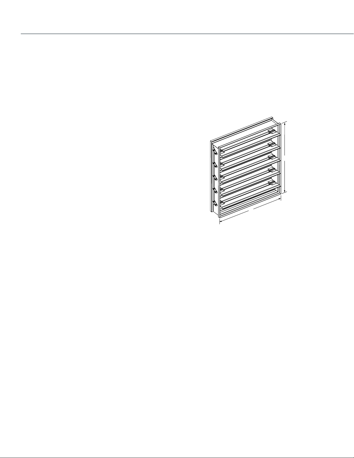
Damper And Actuator Sizing
H
W
M20587
Use the following guidelines to determine the actuator quantity and
torque requirements for your damper configuration.
Determine Damper Actuator Locations
Use the following configuration to determine the amount of
actuator locations your damper will require.
Single Section ≤ 48 x 74 D2, D3
≤ 60 x 74 D1
Dampers will never ship more than 2 sections wide and one
section high.
Configuration
A single section damper will have one actuator location.
A damper that is ≥ 48 x 74 ≤ 96 x 74 will have one actuator
location. This is a two section damper jackshafted together.
A damper that is ≥ 96 x 74 ≤ 144 x 74 will have two actuator
locations. This is a two section damper jackshafted together and a
single section damper.
Exception: 3 section wide ≤ 42 SFT damper will have one actuator
location.
If damper exceeds 74” height a second row is necessary. Apply
same logic above to each row of dampers.
For dampers larger than 144 x 144, please contact the Take-Off
Service (takeoff.service@honeywell.com) for a quote and actuator
location.
Mounting
Internal Mount: Blade drive lever bracket provided only. Customer
is responsible for providing mounting hardware.
External Mount: Actuator shaft will be provided as extension pin kit
to be mounted on side or with jackshaft pre-mounted on damper.
Determining Damper Actuator Torque
Requirements
Use the following procedure to determine the required torque for
your damper.
NOTE: Damper area is measured using the H and W dimensions.
Measuring Damper Area
1. Calculate the damper area in square feet by multiplying the H
dimension by the W dimension.
2. Multiply the damper area by the lb-in. per square foot value
from Table 2 on page 9.
NOTE: The minimum lb-in. per square foot value that can
accommodate tight closeoff and no leakage applications is 5,
regardless of the value shown in the table.
3. Select the highest actuator torque value than the calculated
value.
EXAMPLE:
Low leakage, parallel blade damper:
H dimension = 48 in.
W dimension = 96 in.
Static pressure (in. w.c.) = 2 in. w.c.
Face Velocity = 1000 fpm
48 in. x 96 in. ÷ 144 = 32 sq. ft.
32 sq. ft. x 7 lb-in./sq. ft. = 244 lb-in.
where 7 lb-in./sq. ft = value from Table 2.
In this case you would need an actuator with a minimum nominal
torque of 224 lb-in.
8
Page 9
Table 2. Approximate industry standard damper lb-in.
per sq ft value.
Face Velocity (fpm)/
Static Pressure (in. wc
Leakage Damper
Blades
Low Parallel 4 7 10.5 12 14
Low Opposed 3 5 7.5 8.5 10
Standard Parallel 3 4.5 6.5 7 8
Standard Opposed 2 3 4.5 5 6
500/ 11000/ 21500/ 32000/ 42500/
Damper Sizing
DCA & DAMPER SELECTION
Damper And Actuator Sizing
5
Dampers can be sized using two different methods; actual sizing
and nominal sizing. When actual sizing is used the damper
dimensions will be the same as the sizes ordered. For example,
when a 24 inch x 24 inch D640 damper is ordered, it will be made
such that the height is 24 inches and the width is 24 inches. When
nominal sizing is used, the damper dimensions will be ¼ inch
smaller than the sizes ordered. For example, when a 24 inch x 24
inch D640 is ordered, it will be made such that the height is 23.75
inches and the width is 23.75 inches. No special allowances are
required for dampers that are constructed of multiple sections. For
example, a damper that is 24 inch x 60 inch will be constructed of
two sections. When ordered using nominal sizing, the damper size
will be 23.75 inches high by 59.75 inches wide.
Actual sizing is commonly used when the exact size of the
opening is known or if the damper is not meant to be installed
inside an opening or duct. Nominal sizing, with its ¼ inch
undersizing is commonly used when the damper will be installed
inside an opening or duct and space is needed for positioning or
seal material.
Honeywell’s sizing default is nominal sizing. If actual sizing is
required, please make sure this is specified on the order. For more
information on ordering Honeywell dampers, please contact your
local Honeywell distributor or sales representative.
9
Page 10
Damper And Actuator Sizing
HVAC performance depends largely upon airflow, and Honeywell Volume Control Dampers are built
for both improved airflow and heavy-duty use. Honeywell has long been the leading source for airflow
control, with Volume Control Dampers that meet AMCA-certified Air Performance Standards, the highest
established standards for commercial control dampers. Designed to minimize leakage, Honeywell
dampers will give you efficient, trouble-free operation for years to come.
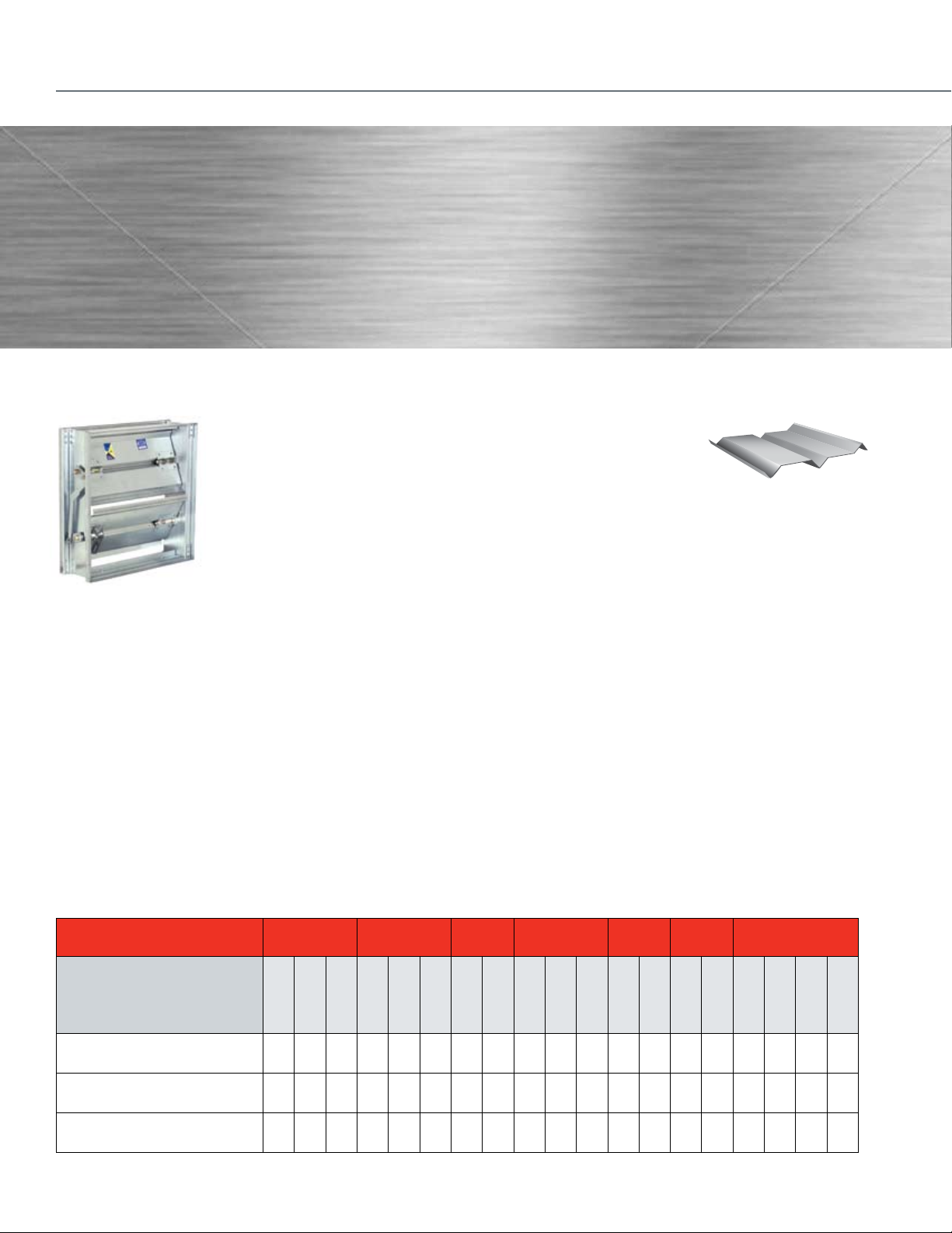
Standard Rectangular Dampers
Durable construction details are the
cornerstone of Honeywell D1, D2 and D3
Volume Control Dampers. They feature
heavy-duty hat channel frames for
dependable operation inside ductwork.
And all models have low-profile top and
bottom frames, creating more free area
while reducing pressure loss and reducing
actuator torque.
The Right Choice
There’s a Honeywell Volume Control Damper that’s just right for your
application. The D1 airfoil extremely low leakage damper presents a
lower resistance to airflow typically used in high pressure systems.
The D2 ultra-low leakage damper keeps leakage to a minimum with
blade and jamb seals, and is designed for medium- to high-pressure
and velocity systems. The D3 low leakage damper is ruggedly built for
applications in medium pressure and velocity systems.
Blade Design
Airfoil Blades - D1 Dampers
Honeywell Airfoil Volume Control Dampers feature blades constructed
of double skin galvanized steel. This design presents a lower resistance
to airflow and has strength that is typically used in high pressure systems.
3-V Blades - D2 and D3 Dampers
Honeywell Volume Control Dampers
feature a 3-V design that’s proven to
meet higher-level system requirements
while minimizing flow-through system loss. Blades are fabricated from
a single thickness of 16-gauge galvanized steel with three horizontal
structural V-grooves running the length of the blade.
Applications And Operation
Honeywell Volume Control Dampers are designed to control airflow
volume in medium- to high-pressure and velocity HVAC systems.
Typical applications include volume control of airflow in zoning, air
handler unit or economizer applications. Dampers are designed
to operate with a wide range of Honeywell electric and pneumatic
actuators. Operating range is from 2000 to 4000 fpm, and 2.5 to 6
inch wg. Spring return and non-spring return actuators are available
with a wide range of output torque ratings to deliver the precise
power needed for your damper application.
Certified Performance
Honeywell certifies that models D2 and D3 are licensed to bear the
AMCA Seal. The ratings shown are based on tests and procedures
performed in accordance with AMCA Publication 511 and comply with
the requirements of the AMCA Certified Ratings Programs. The AMCA
Certified Ratings Seal applies to air performance ratings only.
Aluminum
16
S O O
Frame
Gauge
14
Material
S — Standard
O — Optional
Galvanized
Stainless
D1 Airfoil Extremely Low Leakage
Volume Control Damper
D2 Ultra-Low Leakage
Volume Control Damper
D3 Low Leakage Volume
Control Damper
For a copy of the specification sheet the D1 (63-2671) or D2 and D3 (63-2398), visit customer.honeywell.com.
S O
S O O S O O S O S O O S O S O S O O O
S O O S O O
n/a
12
n/a
n/a n/a
Blade
Seals
Vinyl
Bearings Axles
Silicone
Synthetic
Bronze
Stainless
Steel
S S O O S O S O S O O O
S O O S O S O S O O O
10
Linkage
Material
Stainless
Steel
Stainless
None
Flange
Single
Double
Reverse
Page 11
Damper And Actuator Sizing
Standard Round Dampers Custom Dampers
DCA & DAMPER SELECTION
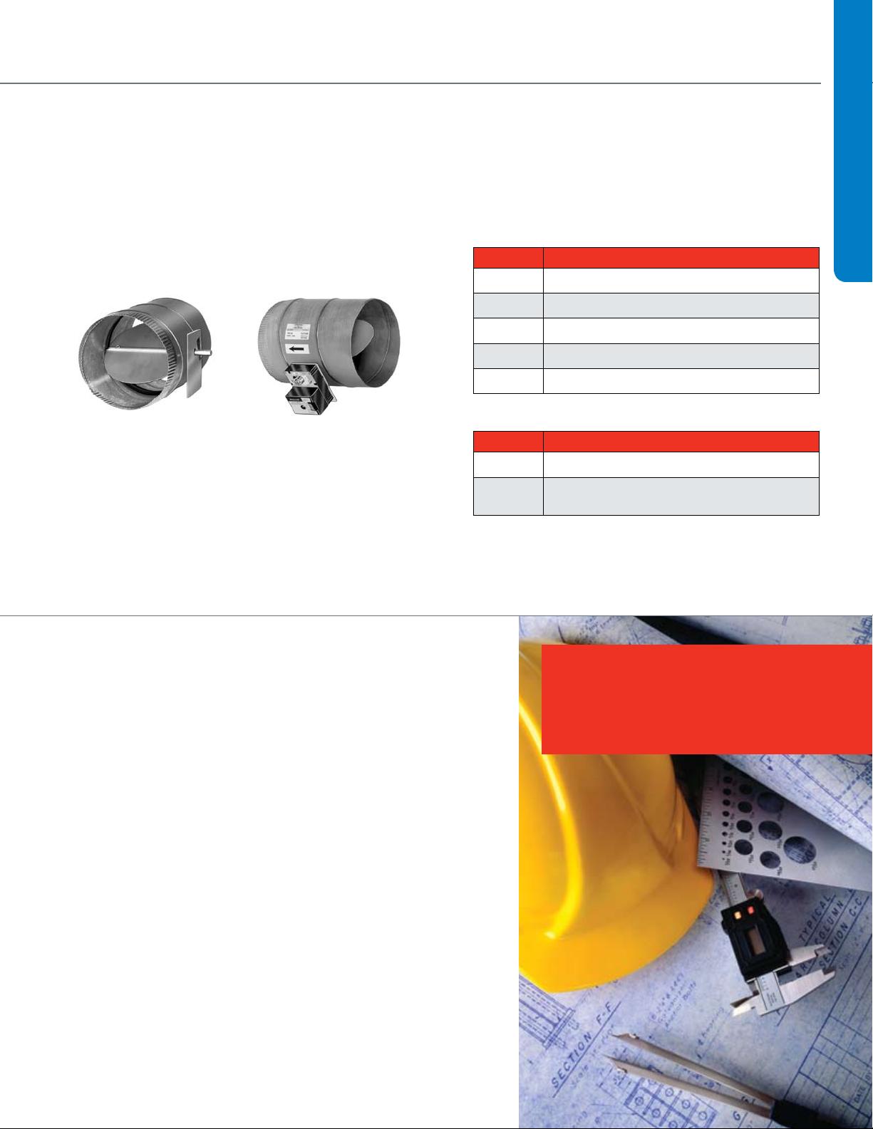
D690 and DM7600 Round Dampers. The 6” to 16” round dampers
are used in zoning systems to control airflow in a round duct. These
dampers come with neoprene and silicone seals for tight close off
and low leakage. The DM7600 includes an actuator that is already
attached to the round damper.
Need a custom damper? Contact the Take-Off Service. Below is a
sample list of the products we frequently quote.
Custom Rectangular Dampers
Number Description
VCD34 Galvanized Insulated Airfoil Damper
VCD40 Aluminum Narrow Frame Airfoil Damper
VCD42 Aluminum Airfoil Damper (Galvanized Frame)
VCD43 Aluminum Airfoil Damper
VCD45 Aluminum thermally broken insulated Damper
Custom Round Dampers
Number Description
VCDR53 Galvanized Round Damper – to 24 inches
VCDRM53 Galvanized Round Multi-Blade Damper –
to 36 inches
Specification Take-Off Service
1. Submit your information in one of the following ways:
a) Email to takeoff.service@honeywell.com (preferred)
b) Fax toll-free to 1-877-880-3386 (local: 1-612-951-1238)
2. Include your desired turn-around time.
3. Take-Off Service staff will send you a confirmation that your email or fax was
received.
We always attempt to have your request finished as soon as possible. Please
note, however, that the quality of the submitted information largely determines the
turn-around time. We will work closely with you to ensure that we have enough
information to move forward as quickly as possible.
4. A final product schedule document will be returned to you following take-off
completion.
Included In the Final Take-Off Document
We send a comprehensive spreadsheet, which contains:
• Acompleteproductschedule
• Baseprice
• DirectionsonhowtoorderHoneywellproducts
• Linkstoproductsubmittals
• Quoteidentificationnumber
Questions
If you have questions about the Honeywell Take-Off Service, please call the dedicated
Take-Off Service phone number or email us at takeoff.service@honeywell.com.
Don’t see what you need?
Take-Off Service Contact Information:
Toll-free: 1-888-664-4092
Local: 1-612-951-1027
11
Page 12
Direct Coupled Actuators
•
ML Non-Spring Return
•
61 Floating, 24 Vac
•
71 Modulating, 24 Vac
Input Signal Type
Fail Safe Mode
ML 61 61
System Controlled Numbers
XXX2B
•
1 Standard
•
2 Includes Declutch Function
Declutch
•
A Feedback w/Accessory
•
B Standard
•
D Cover w/Conduit Connections
•
C Feedback w/Accessory and
Cover w/Conduit Connections
Feedback & Conduit
•
61 (4 Nm) = 35 in-lb
•
74 (8 Nm) = 70 in-lb
To rque
•
MS Spring Return
•
MN Non-Spring Return
•
41 Tw o-Position, 100-250 Va c
•
61 Floating, 24 Vac/dc
•
75 Modulating/Floating, 24 Vac/dc
•
81 Tw o-Position, 24 Vac/dc
Input Signal Type
Fail Safe Mode
MS 75 10
System Controlled Numbers
XX 2 2 A
•
0 No Internal Switches
•
2 Tw o Internal Switches
Auxiliary Switches
•
1 No Feedback
•
2 Voltage Feedback
Feedback
•
A Standard Model
•
H Enhanced Model
Application Type
•
03 Nm = 27 in-lb
•
05 Nm = 44 in-lb
•
10 Nm = 88 in-lb
•
20 Nm = 175 in-lb
•
34 Nm = 300 in-lb
To rque
DIRECT COUPLED ACTUATORS QUICK SELECTION GUIDE
Spring Return,
Low Torque
Spring Return,
High Torque
Precise, reliable performance. Lasting value. Ease
of installation. Everything you look for in directcoupled actuators hinges on quality. And quality
engineering is what makes Honeywell’s complete
line of actuators the top performers in the industry.
Our global engineering team designs and tests
our direct-coupled actuators to exceed rigorous
global standards — and to meet Honeywell’s own
demanding life testing.
But we don’t stop there. Thanks to our continuous
improvement process, Honeywell actuators are now
easier than ever to install. You’ll also benefit from
consistent wiring regardless of signal type, common
accessories and a simplified selection process.
Honeywell’s complete line of building control
products, including valves and actuators, are
already proven in more than three million buildings
worldwide. So when you need spring or nonspring return actuators for your damper and valve
applications, specify Honeywell. We make precision
easy.
Improve Installation Time
• Self-centeringshaftadapterprovidesmounting
flexibility and greater clamping force.
• Commonwiringamongfamiliesforeverysignal
saves installation time.
Decrease Material Cost
• Detachableaccesscoverallowsdirectwiring
without a junction box.
Reduce Inventory
• Signalmodeswitchadaptsmodelstotwo-
position, floating (tri-state), or modulating
(proportional) applications.
Increase Control and Accuracy
• Morethan200repositionstepsformodulating
models provide precise control.
Non-S pring Ret urn,
Low Torque
Non-Spring Return,
High Torque
12
EASY-TO-SELECT MODEL NUMBERS
MS and MN Families
ML Family
Page 13
SPRING RETURN
Order
Specification
Number
S03 Series (3 Nm, 27 lb-in)
MS8103A1030 6 45 <25 • • 0
MS8103A1130 6 45 <25 • • 1
MS4103A1030 6 45 <25 • • 0
MS4103A1130 6 45 <25 • • 1
MS7503A2030 6 90 <25 • • • 0
MS7503A2130 6 90 <25 • • • 1
MS7403A2030 6 90 <25 • • • • 0 •
S05 Series (5 Nm, 44 lb-in)
MS8105A1030 10 45 <25 • • 0
MS8105A1130 10 45 <25 • • 1
MS4105A1030 10 45 <25 • • 0
MS4105A1130 10 45 <25 • • 1
MS7505A2030 10 90 <25 • • • 0
MS7505A2130 10 90 <25 • • • 1
MS7405A2030 10 90 <25 • • • 0 •
S10 Series (10 Nm, 88 lb-in)
MS8110A1008 20 45 <25 • • 0
MS8110A1206 20 45 <25 • • 2
MS4110A1002 20 45 <25 • • 0
MS4110A1200 20 45 <25 • • 2
MS7510A2008 20 90 <25 • • • 0
MS7510A2206 20 90 <25 • • • 2
MS7510H2209 20 90 <25 • • • 2
S20 Series (20 Nm, 175 lb-in)
MS8120A1007 39 45 <25 • • 0
MS8120A1205 39 45 <25 • • 2
MS4120A1001 39 45 <25 • • 0
MS4120A1209 39 45 <25 • • 2
MS7520A2007 39 90 <25 • • • 0
MS7520A2205 39 90 <25 • • • 2
MS7520H2208 39 90 <25 • • • 2
Approximate
Area of Damper
(4.5 lb-in/sq. ft.)
Direct Coupled Actuators
Running Time Power Supply Control Input/Output Auxiliary Knob
Drive
(seconds)
Spring
Return
(seconds)
24
Vac/dc
120-230
Vac
VA Rating
(Running) On/Off
0/2-10
Vdc,
Floating
3 kOhm
NTC,
3-Position
Feedback
(0/2-10
Vdc)
Adj.
Zero
and
Span
SPDT
Auxiliary
Switches
Internal
Minimum
Position
Potentiometer
DCA SELECTION
NON-SPRING RETURN
Power Supply Control Input/Output
Order Specification
Number
N05 Series (5 Nm, 44 lb-in)
MN6105A1011 10 90 • • 0
MN6105A1201 10 90 • • 2
MN7505A2001 10 90 • • 0
MN7505A2209 10 90 • • 2
N10 Series (10 Nm, 88 lb-in)
MN6110A1003 20 90 • • 0
MN6110A1201 20 90 • • 2
MN7510A2001 20 90 • • • • 0
MN7510A2209 20 90 • • • • 2
N20 Series (20 Nm, 175 lb-in)
MN6120A1002 39 90 • • 0
MN6120A1200 39 90 • • 2
MN7220A2007 39 90 • • • 0
MN7220A2205 39 90 • • • 2
N34 Series (34 Nm, 300 lb-in)
MN6134A1003 67 90 • • 0
MN7234A2008 67 90 • • 2
ML6161/7161 (4 Nm, 35 lb-in)
ML6161A2009 8 90 • 1.8 • w/ accessory 0
ML6161A2017 8 420 • 1.8 • w/ accessory 0
ML6161A2025 8 180 • 1.8 • w/ accessory 0
ML6161B2024 8 90 • 1.8 • 0
MS6161B2032 8 420 • 1.8 • 0
ML6161B2073 8 180 • 1.8 • 0
ML6161C2007 8 90 • 1.8 • w/ accessory 0
ML6161D2006 8 90 • 1.8 • 0
MS7161A2008 8 90 • 5.4 • 0
ML6174/7174 (8 Nm, 70 lb-in)
ML6174A2002 16 90 • 2.4 • w/ accessory 0
ML6174A2010 16 180 • 2.4 • w/ accessory 0
ML6174B2019 16 90 • 2.4 • 0
ML6174B2035 16 420 • 2.4 • 0
ML6174D2009 16 90 • 2.4 • 0
ML6174E2008 16 90 • 2.4 • 0
ML7174A2001 16 90 • 5.4 • 0
1
Consult Tradeline catalog for additional models.
2
Assumes standard 1000 fpm system with parallel blade damper. Approximate square foot.
ML7174E2007 16 90 • 5.4 • 0
Approximate Area of
Damper (4.5 lb-in/sq. ft.)
Running
Time 24 Vac/dc 24 Vac
VA Rating
(Running)
On/Off,
Floating 0/2-10 Vdc 2-10 Vdc
Feedback
(0/2-10 Vdc)
SPDT Auxiliary
Switches
13
Page 14
Fire & Smoke Actuators
Honeywell’s complete line of two-position, fast-acting springreturn actuators meet all of your needs for fire and smoke control
applications. All models are designed to meet the UL-555 and
UL-555S high temperature requirements for fire dampers and
combined fire and smoke dampers.
Safety First
As a life safety system component Honeywell is dedicated to
meeting the UL-555 and UL-555S requirements. The elevated
temperature test can be performed at the temperature ratings
of 250ºF or 350ºF. Honeywell only offers models at 350ºF to
meet UL-555 and UL-555S for fire and combined fire and smoke
applications to support the highest level of safety for building
occupants.
Largest Torque Range in the Industry
Honeywell’s fire and smoke actuators are available in 30, 80 and
175 lb-in with the 175 lb-in being the highest torque commercial
fire and smoke actuator available on the market today.
Key Features and Benefits
• Integralspringreturnthatensurestheproperleveloftorque
• Patenteddesignthateliminatedlimitswitches,reducingpower
consumption
• Reliableserviceinsmokecontrolsystemsrequiring
Underwriter’s Laboratories Inc. UL-555 and UL-555S
• Robustdie-castaluminumhousingensures
• Fulllifeoftwo-positionspringreturnreandsmokeactuators
rated up to 350ºF for all critical applications
• Fastactingwithamaximumspringreturntimingof15seconds
• Noaudiblenoiseduringholding
Torque Voltage Spring Direction Description
120 Vac
30 lb-in (3.4 Nm)
80 lb-in (9 Nm)
175 lb-in (20 Nm)
Note: Honeywell's spring return fire and smoke actuators are designed to pass UL-555 and UL-555S 350ºF requirements. They are not designed for HVAC applications. UL-555
and UL-555S requires that all new construction fire and smoke damper jobs have the actuator assembled and tested at the damper manufacturer. A like for like retrofit replacement
or technically equal UL-555 and UL-555S approved device is recommended.
230 Vac
24 Vac
120 Vac
230 Vac
24 Vac
120 Vac
230 Vac
24 Vac
CCW
CW External* ML4115B1008
CCW External* ML4115C1007
CW External* ML4115D1006
CCW External* ML8115A1005
CW External* ML8115B1004
CW
CCW External* MS4309F1005
CW External* MS4709F1014
CCW External* MS4809F1012
CW External* MS8209F1003
CCW External* MS8309F1001
Reversible Design
Fire and smoke, fast acting,
two position spring return, UL-555
and UL-555S ratings up to 350ºF
Fire and smoke, fast acting,
two position spring return, UL-555
and UL555S ratings up to 350ºF
Fire and smoke, fast acting,
two position spring return, UL-555 and
UL-555S ratings up to 350ºF
Number of internal
Auxiliary Switch
External* ML4115A1009
External* MS4209F1007
0 MS4120F1006
2 SPST MS4120F1204
0 MS4620F1005
2 SPST MS4620F1203
0 MS8120F1002
2 SPST MS8120F1200
Model Number
14
Page 15

Section 2: Valve Selection
Control Valve Applications .........................................................17
Control Valve Selection Criteria ..................................................18
2-Way ...................................................................................18
3-Way ...................................................................................20
Fan Coil and Zone Valves .......................................................... 22
Cartridge Cage Valves ................................................................24
Cartridge Globe Valves ...............................................................26
Control Ball Valves ½ - 3”
2-Way NPT NEMA 2 .............................................................28
2-Way NPT NEMA 3R ...........................................................30
Control Ball Valves ½ - 2 ½”
3-Way NPT NEMA 2 .............................................................32
3-Way NPT NEMA 3R .......................................................... 33
Flanged Control Ball Valves 4”- 6”
2-Way Flanged NEMA 2+3R .................................................34
3-Way Flanged NEMA 2+3R .................................................35
NPT Globe Valves ½-3”
With Dedicated Valve Actuators ............................................36
With Direct Coupled Actuators..... .........................................38
Flanged Globe Valves 2 ½ -3”
With Direct Coupled Actuators ..............................................42
Threaded and Flanged Globe Valves 2”-3”
With Tandem Linked Direct Coupled Actuators ....................46
Flanged Globe Valves 2 ½ - 3”
With Dedicated Valve Actuators ............................................48
Flanged Globe Valves 4”-6”
With Tandem Linked Direct Coupled Actuators .....................52
With Dedicated Valve Actuators ............................................54
Flanged Cage Valves 2 ½ - 6” ....................................................55
NPT Globe Valves ½ -3”
With Pneumatic Actuators .....................................................56
Flanged Globe Valves 2 ½ - 3”
With Pneumatic Actuators .....................................................60
Flanged Globe Valves 4”- 6”
With Pneumatic Actuators .....................................................64
Resilient Seat Butterfly Valves
2-Way Electrically-Actuated Control ......................................66
3-Way Electrically-Actuated Control ......................................68
2-Way Pneumatically-Actuated Control .................................72
3-Way Pneumatically-Actuated Control .................................74
VALVE SELECTION
15
Page 16

16
Page 17
Control Valve Applications
Control Valve Applications
VALVE SELECTION
17
Page 18
Control Valve Selection Criteria
2-Way
Unitary Globe
Fan Coil
Attribute Specification
Pipe Size
Pipe Fittings
Static Pressure
Media
Flow Capacity, Cv
Valve Action
Flow Characteristic
Close-off
pressure***
Maximum Seat
Leakage
Rangeability
Trim
In-line
Serviceability
Actuation Options
18
1/2"
3/4" [DN20] • • • • •
1"
1 1/4" [DN32] • •
1 1/2" [DN40] •
2" [DN50] •
2 1/2"
3" [DN80] •
4"
5" [DN125] • • •
6" [DN150] • • •
Other (maximum size)
Multiple ratings per pipe size • • • •
One rating/size above 1/2"
Modified Equal Percentage •
High** (100 psid minimum) •
Medium (40 psid minimum) • •
Varies with actuator • •
ANSI Class III (0.10% Cv max.) 0.02%
ANSI Class IV (0.01% Cv max.) • •
Other (see product data literature) 33 mL/m 0.5%
High (50:1 minimum)
Medium* (15~50:1) •
Low (under 15:1)
Brass, plated brass, bronze
Brass plug /Stainless seat
Pneumatic, low pressure •
Pnuematic bidirectional (Hi-Pr)
Pnuematic spring return (Hi-Pr)
Notes * Best used with supply water reset from outdoor air temperature.
** Can dead-head pumps. Use with VFD-controlled pumps with maximum pressure cut-out
*** Maximum operating differential pressure. Static close-off pressure may be higher. Maximum pressure for quiet service may be less.
**** Stem down to close
***** Stem up to close
[DN15]
[DN25]
[DN65]
[DN100]
Sweat • • • •
NPT Internal Thread • • • • • •
Inverted Flare • • •
ANSI Flange • • •
ANSI 125/150
ANSI 250/300 •
Other 300 psi 300 psi 230 psi
Chilled Water • • • • • •
Hot Water • • • •
Low Pressure Steam N1, N3 •
High Pressure Steam
Direct Acting ****
Reverse Acting ***** • •
Rotary N.O. •
Rotary N.C. •
Equal Percentage •
Linear •
Quick Open • • •
Bubble-tight design •
Stainless Steel
Resilient materials • • • •
Cartridge • • • •
Packing
Rebuild
Electronic Modulating • •
Tri-state floating • •
Pulse Width Modulation •
2-position low voltage • • • o
2-position line voltage • • •
Electric Spring Return • • •
Electronic Fail Safe •
VU52 VU53 VCzA/B
• • • • •
• • • •
N/A
Cartridge
Cage
Cartridge
Globe
V58x2
•
V5011N... V5011F V5011G V5011A V5011B VGF2xS
•
•
N2
•
•
N1, N2
N3
•
•
•
0.05%
•
N3
N1
N2
•
•
•
•
•
•
•
•
Threaded Flanged
0.5%
•
•
•
•
•
•
•
•
•
•
•
•
•
•
•
•
•
•
•
•
•
•
•
• •
• •
• • •
• • •
• • •
• • •
• • •
• • •
• •
•
• • •
• • •
• • •
• •
• • •
• • •
• • •
• • •
• • •
• • •
•
•
•
•
•
•
• • • •
•
•
• • •
•
•
•
•
•
•
•
•
•
•
•
•
Page 19
Control Valve Selection Criteria
Globe Control Ball Butterfly
Pressure-Balanced Threaded Flanged Resilient Seat
Attribute Specification
Pipe Size
Pipe Fittings
Static Pressure
Media
Flow Capacity, Cv
Valve Action
Flow Characteristic
Close-off
pressure***
Maximum Seat
Leakage
Rangeability
Trim
In-line
Serviceability
Actuation Options
1/2"
3/4" [DN20] •
1"
1 1/4" [DN32] • •
1 1/2" [DN40] • •
2" [DN50] • • •
2 1/2"
3" [DN80] • • • •
4"
5" [DN125] • • • •
6" [DN150] • • • •
Other (maximum size) 20" [DN500]
Multiple ratings per pipe size • • •
One rating/size above 1/2" • • •
Modified Equal Percentage • • • •
High** (100 psid minimum) • • • • • •
Medium (40 psid minimum) • •
Varies with actuator
ANSI Class III (0.10% Cv max.)
ANSI Class IV (0.01% Cv max.) • • • • • •
Other (see product data literature)
High (50:1 minimum) • • • •
Medium* (15~50:1) o
Low (under 15:1) • •
Brass, plated brass, bronze •
Brass plug /Stainless seat
Pnuematic bidirectional (Hi-Pr) • •
Pnuematic spring return (Hi-Pr) • •
Notes * Best used with supply water reset from outdoor air temperature.
** Can dead-head pumps. Use with VFD-controlled pumps with maximum pressure cut-out
*** Maximum operating differential pressure. Static close-off pressure may be higher. Maximum pressure for quiet service may be less.
**** Stem down to close
***** Stem up to close
[DN15]
[DN25]
[DN65]
[DN100]
Sweat
NPT Internal Thread • •
Inverted Flare
ANSI Flange • • • •
ANSI 125/150 • •
ANSI 250/300
Other 230 psi 360 psi 250 psi
Chilled Water • • • • • •
Hot Water • • • • • •
Low Pressure Steam •
High Pressure Steam •
Direct Acting **** • •
Reverse Acting *****
Rotary N.O. o o • o
Rotary N.C. • • •
Equal Percentage •
Linear • •
Quick Open
Bubble-tight design • •
Stainless Steel • • • •
Resilient materials • •
Cartridge
Packing • • • •
Rebuild •
Electronic Modulating • • • • • •
Tri-state floating • • • • • •
Pulse Width Modulation
2-position low voltage • • • Limited
2-position line voltage • o o • •
Electric Spring Return • • • • Limited
Electronic Fail Safe
Pneumatic, low pressure • Limited
V5862A3 VGF2xP VBN2 VBF2 VFF1 VFF2
•
• •
• • • •
• • • •
2-Way
VALVE SELECTION
19
Page 20
Control Valve Selection Criteria
3-Way
Unitary Globe
Fan Coil
Attribute Specification
Pipe Size
Pipe Fittings
Static Pressure
Media
Flow Capacity, Cv
Valve Action
A-port Flow
Characteristic
B-port Flow
Characteristic
Close-off
pressure***
Maximum
Seat
Leakage**
Rangeability
Trim
In-line
Serviceability
Actuation Options
20
1/2"
3/4" [DN20] • • • •
1"
1 1/4" [DN32] • • •
1 1/2" [DN40] • •
2" [DN50] •
2 1/2"
3" [DN80] • • •
4"
5" [DN125] • • • •
6" [DN150] • • • •
Other (maximum size)
Multiple ratings per pipe size • • • • •
One rating/size above 1/2" • • • • •
Mixing A-B-AB porting • • • • •
Mixing A-AB-B porting • •
Diverting AB-B-A porting • •
Diverting A-AB-B porting •
Modified Equal Percentage •
Modified Equal Percentage
High (60 psid minimum) • • •
Medium (30 psid minimum) •
ANSI Class III (0.10% Cv max.) • •
ANSI Class IV (0.01% Cv max.) • •
Other (see product data literature) 33 mL/m A = 0.5%
High (50:1 minimum)
Medium* (15~50:1) •
Low (under 15:1)
Brass, plated brass, bronze • • • •
Pneumatic, low pressure •
Pnuematic bidirectional (Hi-Pr)
Pnuematic spring return (Hi-Pr)
Notes * Best used with supply water reset from outdoor air temperature.
** A port specification
*** A-port maximum operating differential pressure. Static close-off pressure may be higher. Maximum pressure for quiet service may be less.
**** Stem down to close
***** Stem up to close
"Limited" = not available in large sizes
[DN15]
[DN25]
[DN65]
[DN100]
Sweat • • •
NPT Internal Thread • • • • •
Inverted Flare • •
ANSI Flange • • • •
ANSI 125/150 • • • • •
ANSI 250/300 • •
Other 300 psi 300 psi 230 psi 230 psi
Chilled Water • • • • • • • • •
Hot Water • • • • • • • • •
Equal Percentage • • •
Linear • • • • •
Quick Open • •
Linear •
Linear, Reduced Cv • •
Total Constant Flow • • • • • •
Quick Open •
Varies with actuator • • • • • •
Bubble-tight design •
Stainless Steel o • •
Resilient materials • • •
Cartridge • • •
Packing •
Rebuild • • •
Electronic Modulating • • • • • • • •
Tri-state floating • • • • • • • •
Pulse Width Modulation •
2-position low voltage • • o o • • • • •
2-position line voltage • •
Electric Spring Return • • •
Electronic Fail Safe •
VU54 VCzM/N V58x3
Cartridge
Cage
• • • •
• • • •
N/A
Cartridge Globe Threaded Flanged
V5863A3
• • • • • • •
V5013N... V5013B V5013C VGF3xLD VGF3xEM
•
•
•
•
•
•
• • •
• • • •
• • • •
•
• • • •
• • • •
• • • •
• • • •
Page 21
Control Valve Selection Criteria
Control Ball Butterfly
Threaded Flanged Resilient Seat
Attribute Specification
Pipe Size
Pipe Fittings
Static Pressure
Media
Flow Capacity, Cv
Valve Action
A-port Flow
Characteristic
B-port Flow
Characteristic
Close-off
pressure***
Maximum
Seat
Leakage**
Rangeability
Trim
In-line
Serviceability
Actuation Options
1/2"
3/4" [DN20] •
1"
1 1/4" [DN32] •
1 1/2" [DN40] •
2" [DN50] • •
2 1/2"
3" [DN80] • •
4"
5" [DN125] • • •
6" [DN150] • • •
Other (maximum size) 20" [DN500]
Multiple ratings per pipe size • •
One rating/size above 1/2" • •
Mixing A-B-AB porting • • •
Mixing A-AB-B porting •
Diverting AB-B-A porting • o •
Diverting A-AB-B porting •
Modified Equal Percentage • • • •
Modified Equal Percentage • •
High (60 psid minimum) • • •
Medium (30 psid minimum) • • •
ANSI Class III (0.10% Cv max.)
ANSI Class IV (0.01% Cv max.) • A-port • •
Other (see product data literature) B-port
High (50:1 minimum) • •
Medium* (15~50:1) o
Low (under 15:1) • •
Brass, plated brass, bronze •
Pnuematic bidirectional (Hi-Pr) • •
Pnuematic spring return (Hi-Pr) • •
Notes * Best used with supply water reset from outdoor air temperature.
** A port specification
*** A-port maximum operating differential pressure. Static close-off pressure may be higher. Maximum pressure for quiet service may be less.
**** Stem down to close
***** Stem up to close
"Limited" = not available in large sizes
[DN15]
[DN25]
[DN65]
[DN100]
Sweat
NPT Internal Thread •
Inverted Flare
ANSI Flange • • •
ANSI 125/150 •
ANSI 250/300
Other 360 psi 250 psi
Chilled Water • • • •
Hot Water • • • •
Equal Percentage
Linear
Quick Open
Linear
Linear, Reduced Cv • •
Total Constant Flow
Quick Open
Varies with actuator
Bubble-tight design • •
Stainless Steel •
Resilient materials • •
Cartridge
Packing • •
Rebuild •
Electronic Modulating • • • •
Tri-state floating • • • •
Pulse Width Modulation
2-position low voltage • • Limited
2-position line voltage o o • •
Electric Spring Return • • Limited
Electronic Fail Safe
Pneumatic, low pressure Limited
VBN3 VBF3 VFF3
•
•
• • •
• • •
VFF6
•
3-Way
VALVE SELECTION
21
Page 22
Fan Coil and Zone Valves
Honeywell Fan Coil and Zone Valves family (VU Series) have
withstood the test of time as a reliable and dependable product.
With a Cv range suitable for anything from radiator panels to fan
coil units and both normally open and normally closed spring
return functions, it’s easy to select a model that fits your needs.
Additionally you can choose between line voltage or low voltage
actuators as well as three different types of pipe fittings: Female
NPT, Sweat, and Inverted flare.
(Cv)
Actuator O.S. Number
1/2 in. flexible conduit hole • • • • • •
Valve
Action
Normally Open
Normally Closed
Connec tion
Type
Mixing
VU52SN1076
2-Way
3-Way
Valve Size
(inches)
Valve Size
(inches)
Connec tion
Type
f NPT 1.0 Cv
Sweat 1.0 Cv
1/2"
3/4"
1'' f NPT 8.0 Cv
1/2"
3/4"
1"
1/2"
3/4"
1"
f NPT 2.5 Cv
Sweat 2.5 Cv
f NPT 3.5 Cv
Sweat 3.5 Cv
f NPT 3.5 Cv
Sweat 3.5 Cv
Sweat 5.0 Cv
f NPT 8.0 Cv
Sweat 8.0 Cv
f NPT 1.0 Cv
Sweat 1.0 Cv
f NPT 2.5 Cv
Sweat 2.5 Cv
Inverted Flare 3.5 Cv
f NPT 3.5 Cv
Sweat 3.5 Cv
f NPT 3.5 Cv
Sweat 3.5 Cv
f NPT 5.0 Cv
Sweat 5.0 Cv
f NPT 8.0 Cv
Sweat 8.0 Cv
f NPT 8.0 Cv
Sweat 8.0 Cv
Flow Capacity
(Cv)
Inverted Flare 4.0 Cv
f NPT 4.0 Cv
Sweat 4.0 Cv
f NPT 4.0 Cv
f NPT 5.0 Cv
Sweat 5.0 Cv
f NPT 7.0 Cv
Sweat 7.0 Cv
f NPT 7.0 Cv
Sweat 7.0 Cv
Power Supply Voltage 120 Vac 208 Vac 230 Vac 120 Vac 120 Vac 120 Vac
Control 2-Position SPST • • • • • •
Aux Switch SPST 2.2 A/120 Vac
Maximum Timing Seconds @ 60 Hz, Driving 15 15 15 15 15 15
Fail Safe Action
Electrical Connections Leadwire Length, in. 6 18 6 6 18 6
Manual Override (on power failure, auto reset) • • • • • •
Nickel plated motors Condensing Atmosphere •
Flow Capacity
Valve
Action
Common Features
• Maximum static water pressure: 300 psig
• Ambient temp range: 34-104°F
(at 34-200°F medium temperature)
• 3-way valve is diverting type
• Long service life with patented ball seal
• Quick opening / soft closing for optimal
2-position control
• Manual opener
VU443A1008 VU443A1024 VU443A1115 VU443A1180 VU443E1009 VU444A1007
Frequency 60 Hz 60 Hz 50 / 60 Hz 60 Hz 60 Hz 60 Hz
Power (60 Hz) 5 VA 5 VA 5 VA 5 VA 5 VA 5 VA
Fail Safe 6 6 6 6 6 6
N.C. N.C. N.C. N.C. N.C.
Valve O.S.
Number
VU52N1027
VU52S2002
VU52N1035
VU52S2010
VU52N1019
VU52S2028
VU52S2036
VU52S2044
VU52N1001
VU52S2051
VU52N1068
VU53N1041
VU53S2018
VU53N1058
VU53S2026
VU53F1024
VU53N1009
VU53S2034
VU53N1033
VU53S2042
VU53N1066
VU53S2075
VU53N1017
VU53S2059
VU53N1026
VU53S2000
Valve O.S.
Number
VU54F1022
VU54N1007
VU54S2008
VU54N1031
VU54N1049
VU54S2057
VU54N1015
VU54S2016
VU54N1023
VU54S2024
50 50 50 50 50
50 50 50 50 50
30 30 30 30 30
30 30 30 30 30
20 20 20 20 20
20 20 20 20 20
20 20 20 20 20
20 20 20 20 20
20 20 20 20 20
15 15 15 15 15
15 15 15 15 15
10 10 10 10 10
10 10 10 10 10
10 10 10 10 10
10 10 10 10 10
2-way Valves Close-off
3-way Valves Close-off
2-way N.O.
3-way N.O./N.C.
50
50
30
30
20
20
20
20
15
10
10
10
20
20
10
20
15
15
10
10
10
10
22
Page 23
Fan Coil and Zone Valves
Valve Size
2-Way
Valve Size
3-Way
(inches)
(inches)
Connec tion
Type
f NPT 1.0 Cv
Sweat 1.0 Cv
1/2"
3/4"
1" f NPT 8.0 Cv
1/2"
3/4"
1"
1/2"
3/4"
1"
f NPT 2.5 Cv
Sweat 2.5 Cv
f NPT 3.5 Cv
Sweat 3.5 Cv
f NPT 3.5 Cv
Sweat 3.5 Cv
Sweat 5.0 Cv
f NPT 8.0 Cv
Sweat 8.0 Cv
f NPT 1.0 Cv
Sweat 1.0 Cv
f NPT 2.5 Cv
Sweat 2.5 Cv
Inverted Flare 3.5 Cv
f NPT 3.5 Cv
Sweat 3.5 Cv
f NPT 3.5 Cv
Sweat 3.5 Cv
f NPT 5.0 Cv
Sweat 5.0 Cv
f NPT 8.0 Cv
Sweat 8.0 Cv
f NPT 8.0 Cv
Sweat 8.0 Cv
Flow Capacity
(Cv)
Inverted Flare 4.0 Cv
f NPT 4.0 Cv
Sweat 4.0 Cv
f NPT 4.0 Cv
f NPT 5.0 Cv
Sweat 5.0 Cv
f NPT 7.0 Cv
Sweat 7.0 Cv
f NPT 7.0 Cv
Sweat 7.0 Cv
(Cv)
Valve
Actuator O.S. Number
1/2 in. flexible conduit hole • • • • • • •
Valve
Action
Normally Open
Normally Closed
Connec tion
Type
Mixing
Frequency 60 Hz 50 / 60 Hz 60 Hz 50 / 60 Hz 50 / 60 Hz 50 / 60 Hz 50 / 60 Hz
Power (60 Hz) 5 VA 5 VA 5 VA 0.32 A 0.32 A 0.32 A 0.32 A
Valve O.S.
Number
VU52N1027
VU52S2002
VU52N1035
VU52S2010
VU52N1019
VU52S2028
VU52SN1076
VU52S2036
VU52S2044
VU52N1001
VU52S2051
VU52N1068
VU53N1041
VU53S2018
VU53N1058
VU53S2026
VU53F1024
VU53N1009
VU53S2034
VU53N1033
VU53S2042
VU53N1066
VU53S2075
VU53N1017
VU53S2059
VU53N1026
VU53S2000
Valve O.S.
Number
VU54F1022
VU54N1007
VU54S2008
VU54N1031
VU54N1049
VU54S2057
VU54N1015
VU54S2016
VU54N1023
VU54S2024
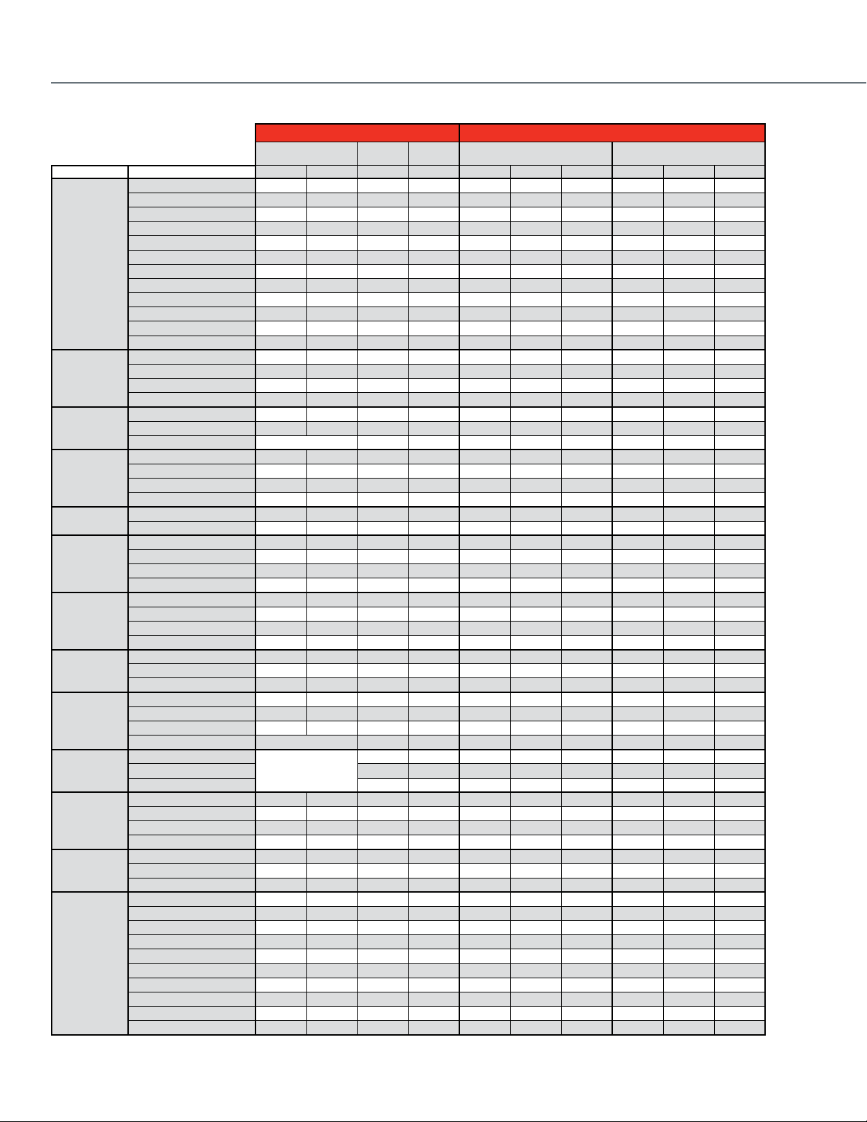
Power Supply Voltage 227 Vac 230 Vac 120 Vac 24 Vac 24 Vac 24 Vac 24 Vac
Control 2-Position SPST • • • • • • •
Aux Switch SPST
Maximum Timing Seconds @ 60 Hz, Driving 15 15 15 15 15 15 15
Fail Safe Action
Electrical Connections Leadwire Length, in. 18 6 6 6 6 6 6
Manual Override (on power failure, auto reset) • • • • • • •
Nickel plated motors Condensing Atmosphere • • •
Flow Capacity
Action
VU444A1098 VU444A1106 VU444A1155 VU843A1004 VU843A1087 VU844A1003 VU844A1060
Fail Safe 6 6 6 6 6 6 6
2-way N.O.
3-way N.O./N.C.
2-way N.O.
3-way N.O./N.C.
2-way N.O.
3-way N.O./N.C.
N.C. N.C.
2-way N.O.
3-way N.O./N.C.
2-way N.O.
3-way N.O./N.C.
2-way Valves Close-off
50 50 50 50 50
50 50 50 50 50
30 30 30 30 30
30 30 30 30 30
20 20 20 20 20
20 20 20 20 20
20 20 20 20 20
20 20 20 20 20
15 15 15 15 15
10 10 10 10 10
10 10 10 10 10
10 10 10 10 10
50 50
50 50
30 30
30 30
20 20
20 20
20 20
20 20
20 20
15 15
15 15
10 10
10 10
10 10
10 10
3-way Valves Close-off
20 20 20 20 20
20 20 20 20 20
10 10 10 10 10
20 20 20 20 20
15 15 15 15 15
15 15 15 15 15
10 10 10 10 10
10 10 10 10 10
10 10 10 10 10
10 10 10 10 10
ValVe Selection
23
Page 24
Cartridge Cage Valves
Honeywell Cartridge Cage Valves family (VC Series) are highly serviceable
and completely rebuildable.
Select from 2-position (both low and line voltage), oating, and modulating
actuators, and fail-safe actuators with congurable open/closed
functionality on power failure depending on the application. Since these
valves are not sensitive to ow direction; they can do both mixing and
diverting without changing anything except the piping.
Actuator O.S. Number
Power Supply Voltage 24 Vac 24 Vac 24 Vac 100-130 Vac 200-240 Vac 24 Vac 24 Vac
Control 2-10 Vdc •
4-20 mA (external 500 Ohm resistor) •
Aux Switch SPDT Class II 2.2 A 2.2 A
Fail Safe Action
Reversible Operation Wiring Change • •
Stroke Timing Seconds @ 60 Hz (Drive) 120 120 120 6 6 6 6
Electrical Connection Cable length, in. 60 60 60 39.4 39.4 60 60
Valve Size
2-Way
Valve Size
3-Way Mixing/ Diverting
(inches)
1/2"
3/4"
1"
1-1/4"
(inches)
1/2"
3/4"
1"
1-1/4"
Connection
Connection
Flow Capacity
Type
f NPT 0.7
Sweat 0.7
f NPT 1.3
Sweat 1.3
Sweat 1.9
f NPT 1.9
Sweat 2.3
f NPT 2.3
f NPT 3.5 Linear
Sweat 3.5 Linear
f NPT 3.9 Modified Equal %
Sweat 3.9 Modified Equal %
f NPT 4.7 Linear
Sweat 4.7 Linear
f NPT 4.2 Modified Equal %
Sweat 4.2 Modified Equal %
f NPT 6.6
Sweat 6.6
f NPT 7
Sweat 7
Flow Capacity
Type
f NPT 0.7
Sweat 0.7
f NPT 1.5
Sweat 1.5
f NPT 1.5
Sweat 1.5
f NPT 2.7
Sweat 2.7
f NPT 3.7 Linear
Sweat 3.7 Linear
f NPT 4.2 Modified Equal %
Sweat 4.2 Modified Equal %
f NPT 6.6
Sweat 6.6
f NPT 8.3
Sweat 8.3
f NPT 9
Sweat 9
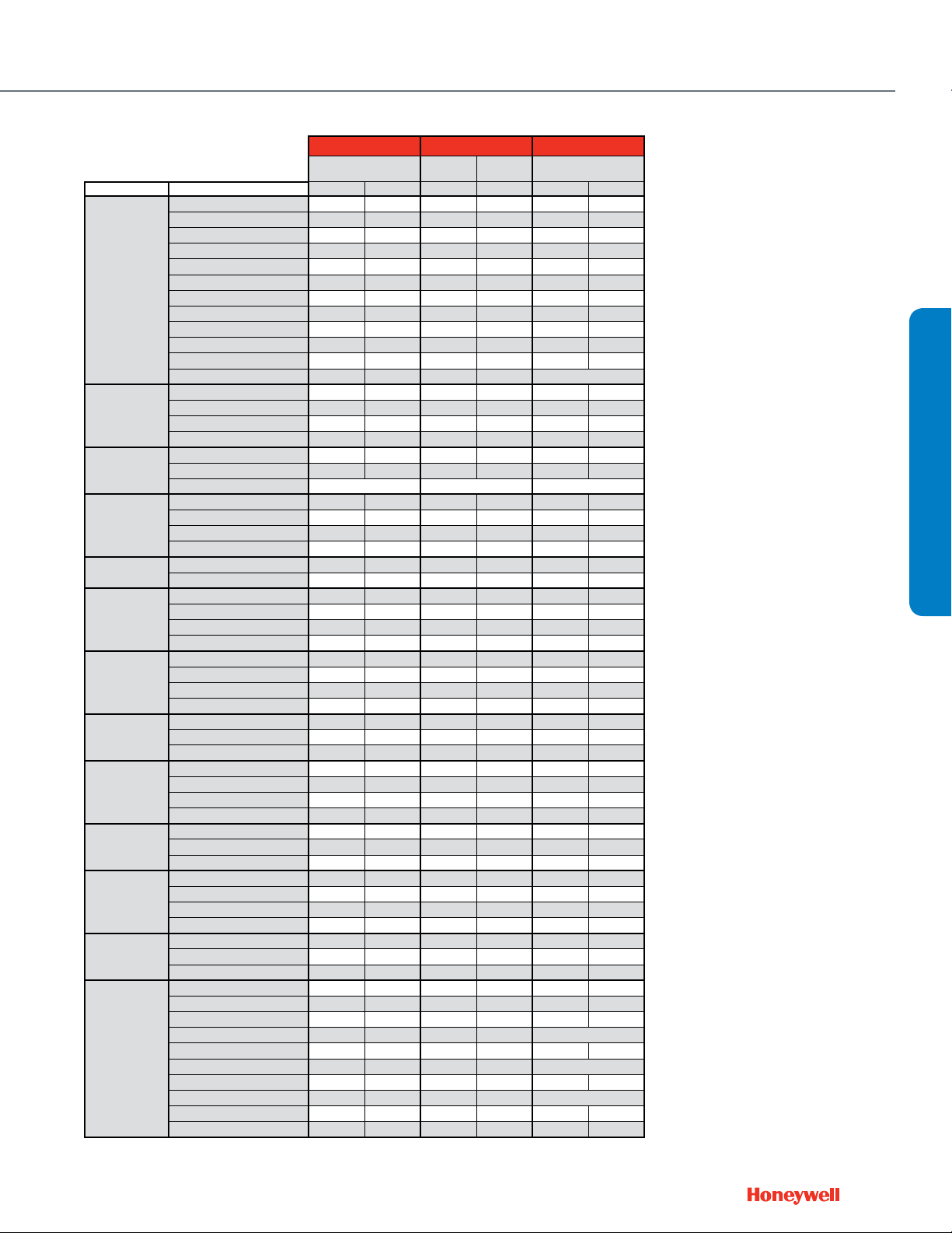
VC6834ZZ11 VC6934ZZ11 VC7934ZZ11 VC4011ZZ11 VC4013ZZ11 VC8114ZZ11 VC8714ZZ11
Frequency 50/60 Hz 50/60 Hz 50/60 Hz 50/60 Hz 50/60 Hz 60 Hz 60 Hz
Power 6 VA 6 VA 6 VA 6 VA 6 VA 6 VA 6 VA
Floating • •
2-Position SPDT • •
2-Position SPST • • • •
Pulse Width Modulation
Stay in Place Stay in Place Stay in Place Stay in Place Stay in Place Stay in Place Stay in Place
DIP Switch
Fail Safe
Plenum-rated cable • • • • •
1/2 in. flexible conduit adapter • • • • •
(Cv)
(Cv)
Flow
Characteristic
Modified Equal %
Linear
Flow
Characteristic
Modified Equal %
Linear
VCZBB3500 VCZBB3500 VCZBB3500
VCZAA3500 VCZAA3500 VCZAA3500
VCZBB3600 VCZBB3600 VCZBB3600
VCZAA3600 VCZAA3600 VCZAA3600
VCZAA3800 VCZAA3800 VCZAA3800
VCZBB3800 VCZBB3800 VCZBB3800
VCZAA3400 VCZAA3400 VCZAA3400
VCZBB3400 VCZBB3400 VCZBB3400
VCZBB3100 VCZBB3100 VCZBB3100 VCZBB1100 VCZBB1100 VCZBB1100 VCZBB1100
VCZAA3100 VCZAA3100 VCZAA3100 VCZAA1100 VCZAA1100 VCZAA1100 VCZAA1100
VCZAL3400 VCZAL3400 VCZAL3400
VCZAM3400 VCZAM3400 VCZAM3400
VCZAL3100 VCZAL3100 VCZAL3100 VCZAL1100 VCZAL1100 VCZAL1100 VCZAL1100
VCZAM3100 VCZAM3100 VCZAM3100 VCZAM1100 VCZAM1100 VCZAM1100 VCZAM1100
VCZAR3400 VCZAR3400 VCZAR3400
VCZAS3400 VCZAS3400 VCZAS3400
VCZAR3100 VCZAR3100 VCZAR3100 VCZAR1100 VCZAR1100 VCZAR1100 VCZAR1100
VCZAS3100 VCZAS3100 VCZAS3100 VCZAS1100 VCZAS1100 VCZAS1100 VCZAS1100
VCZBD3100 VCZBD3100 VCZBD3100 VCZBD1100 VCZBD1100 VCZBD1100 VCZBD1100
VCZBE3100 VCZBE3100 VCZBE3100 VCZBE1100 VCZBE1100 VCZBE1100 VCZBE1100
VCZNB7500 VCZNB7500 VCZNB7500
VCZMA7500 VCZMA7500 VCZMA7500
VCZNB7600 VCZNB7600 VCZNB7600
VCZMA7600 VCZMA7600 VCZMA7600
VCZNB7800 VCZNB7800 VCZNB7800
VCZMA7800 VCZMA7800 VCZMA7800
VCZNB7400 VCZNB7400 VCZNB7400
VCZMA7400 VCZMA7400 VCZMA7400
VCZNB7100 VCZNB7100 VCZNB7100 VCZNB6100 VCZNB6100 VCZNB6100 VCZNB6100
VCZMA7100 VCZMA7100 VCZMA7100 VCZMA6100 VCZMA6100 VCZMA6100 VCZMA6100
VCZMK7400 VCZMK7400 VCZMK7400
VCZML7400 VCZML7400 VCZML7400
VCZMK7100 VCZMK7100 VCZMK7100 VCZMK6100 VCZMK6100 VCZMK6100 VCZMK6100
VCZML7100 VCZML7100 VCZML7100 VCZML6100 VCZML6100 VCZML6100 VCZML6100
VCZMR7100 VCZMR7100 VCZMR7100 VCZMR6100 VCZMR6100 VCZMR6100 VCZMR6100
VCZMS7100 VCZMS7100 VCZMS7100 VCZMS6100 VCZMS6100 VCZMS6100 VCZMS6100
VCZND7100 VCZND7100 VCZND7100 VCZND6100 VCZND6100 VCZND6100 VCZND6100
VCZNE7100 VCZNE7100 VCZNE7100 VCZNE6100 VCZNE6100 VCZNE6100
Non-Fail Safe
Valve O.S. Number
Valve O.S. Number
VCZNE6100
24
Page 25
Common Features
• 2-way straight-through or 3-way mixing/diverting body congurations
• Corrosion resistant, engineered plastic actuator housing
• 60 psid close-off on all models
• Fast acting 2-position actuator with soft close technology
• Position indicator/manual override lever standard
• Replaceable cartridge rebuilds valve to factory specications without
removing valve body from piping
• 300 psi operating pressure
• Combination position indicator/manual
ush-and-ll manual lever on all actuators
2-Way
3-Way Mixing/ Diverting
* Also applies to 2-position valve-actuator applications
Valve Size
(inches)
1/2"
3/4"
1"
1-1/4"
Valve Size
(inches)
1/2"
3/4"
1"
1-1/4"
Actuator O.S. Number
Power Supply Voltage 24 Vac 24 Vac
Control 2-10 Vdc •
4-20 mA (external 500 Ohm resistor) •
2-Position SPDT • •
2-Position SPST •
Aux Switch SPDT Class II
Fail Safe Action
Reversible Operation Wiring Change • •
Stroke Timing Seconds @ 60 Hz (Drive) 120 60 / 120
Electrical Connection Cable length, in. 60 60
Connection
Type
f NPT 0.7
Sweat 0.7
f NPT 1.3
Sweat 1.3
Sweat 1.9
f NPT 1.9
Sweat 2.3
f NPT 2.3
f NPT 3.5 Linear
Sweat 3.5 Linear
f NPT 3.9 Modified Equal %
Sweat 3.9 Modified Equal %
f NPT 4.7 Linear
Sweat 4.7 Linear
f NPT 4.2 Modified Equal %
Sweat 4.2 Modified Equal %
f NPT 6.6
Sweat 6.6
f NPT 7
Sweat 7
Connection
Type
f NPT 0.7
Sweat 0.7
f NPT 1.5
Sweat 1.5
f NPT 1.5
Sweat 1.5
f NPT 2.7
Sweat 2.7
f NPT 3.7 Linear
Sweat 3.7 Linear
f NPT 4.2 Modified Equal %
Sweat 4.2 Modified Equal %
f NPT 6.6
Sweat 6.6
f NPT 8.3
Sweat 8.3
f NPT 9
Sweat 9
Pulse Width Modulation • •
Plenum-rated cable • •
1/2 in. flexible conduit adapter • •
Flow Capacity
(Cv)
Characteristic
Modified Equal %
Flow Capacity
(Cv)
Characteristic
Modified Equal %
Cartridge Cage Valves
VC6936ZZ11-530 VC7936ZZ11-529
Frequency 50/60 Hz 50/60 Hz
Power 12 VA 12 VA
Floating • •
Electronic NO/NC Electronic NO/NC
DIP Switch •
Fail Safe 12 12
Flow
VC6936BB1500 VC7936BB1500
VC6936AA1500 VC7936AA1500
VC6936BB1600 VC7936BB1600
VC6936AA1600 VC7936AA1600
VC6936AA1800 VC7936AA1800
VC6936BB1800 VC7936BB1800
VC6936AA1400 VC7936AA1400
VC6936BB1400 VC7936BB1400
VC6936BB1100 VC7936BB1100
VC6936AA1100 VC7936AA1100
VC6936AL1400 VC7936AL1400
VC6936AM1400 VC7936AM1400
VC6936AL1100 VC7936AL1100
VC6936AM1100 VC7936AM1100
VC6936AR1400 VC7936AR1400
VC6936AS1400 VC7936AS1400
VC6936AR1100 VC7936AR1100
Linear
Flow
Linear
VC6936AS1100 VC7936AS1100
VC6936BD1100 VC7936BD1100
VC6936BE1100 VC7936BE1100
VC6936NB6500 VC7936NB6500
VC6936MA6500 VC7936MA6500
VC6936NB6600 VC7936NB6600
VC6936MA6600 VC7936MA6600
VC6936NB6800 VC7936NB6800
VC6936MA6800 VC7936MA6800
VC6936NB6400 VC7936NB6400
VC6936MA6400 VC7936MA6400
VC6936NB6100 VC7936NB6100
VC6936MA6100 VC7936MA6100
VC6936MK6400 VC7936MK6400
VC6936ML6400 VC7936ML6400
VC6936MK6100 VC7936MK6100
VC6936ML6100 VC7936ML6100
VC6936MR6100 VC7936MR6100
VC6936MS6100 VC7936MS6100
VC6936ND6100 VC7936ND6100
VC6936NE6100 VC7936NE6100
Fail Safe
Y-pack O.S. Number
Y-pack O.S. Number
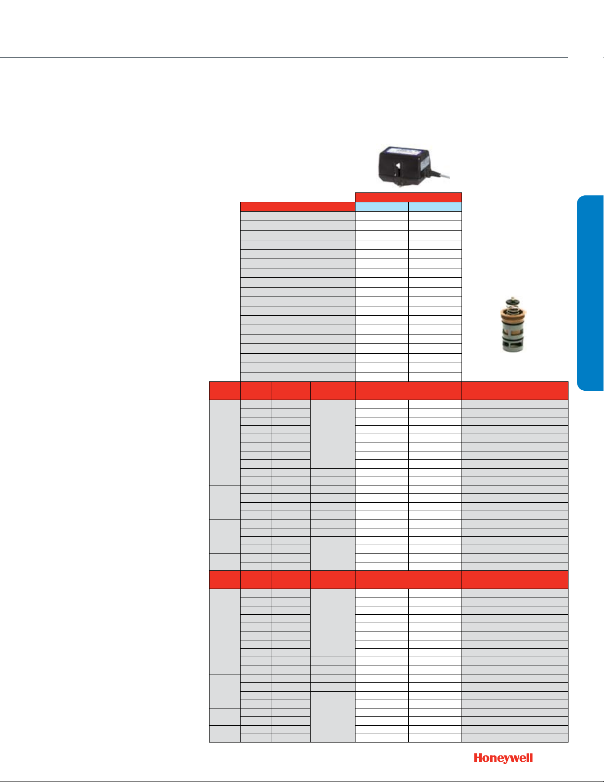
Honeywell’s Cartridge Cage Valves
feature a field replaceable cartridge
for all working parts
Replacement Cartridge
Floating / Modulating
VCZZ3500 VCZZ1500
VCZZ3500 VCZZ1500
VCZZ3600 VCZZ1600
VCZZ3600 VCZZ1600
VCZZ3800 VCZZ1800
VCZZ3800 VCZZ1800
VCZZ3400 VCZZ1400
VCZZ3400 VCZZ1400
VCZZ3100 VCZZ1100*
VCZZ3100 VCZZ1100*
VCZZ3400 VCZZ1400
VCZZ3400 VCZZ1400
VCZZ3100 VCZZ1100*
VCZZ3100 VCZZ1100*
VCZZ3400 VCZZ1400
VCZZ3400 VCZZ1400
VCZZ3100 VCZZ1100*
VCZZ3100 VCZZ1100*
VCZZ3100 VCZZ1100*
VCZZ3100 VCZZ1100*
Replacement Cartridge
Floating / Modulating
VCZZ7500 VCZZ6500
VCZZ7500 VCZZ6500
VCZZ7600 VCZZ6600
VCZZ7600 VCZZ6600
VCZZ7800 VCZZ6800
VCZZ7800 VCZZ6800
VCZZ7400 VCZZ6400
VCZZ7400 VCZZ6400
VCZZ7100 VCZZ6100*
VCZZ7100 VCZZ6100*
VCZZ7400 VCZZ6400
VCZZ7400 VCZZ6400
VCZZ7100 VCZZ6100*
VCZZ7100 VCZZ6100*
VCZZ7100 VCZZ6100*
VCZZ7100 VCZZ6100*
VCZZ7100 VCZZ6100*
VCZZ7100 VCZZ6100*
Replacement Cartridge
Electronic Fail Safe
Replacement Cartridge
Electronic Fail Safe
ValVe Selection
25
Page 26
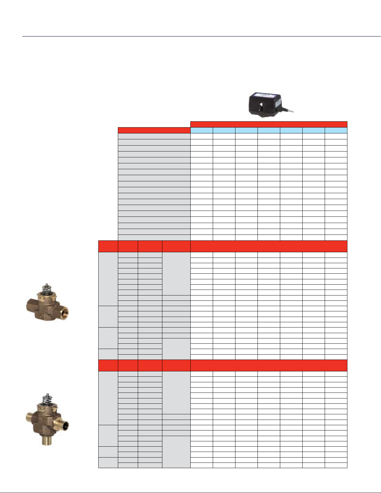
Cartridge Globe Valves
For more than 50 years, Honeywell has manufactured
the V58 series of premium Cartridge Globe Valves. The
compact size and replacement capabilities make it a great
choice for controlling modulating unitary equipment.
Valves 1" and larger feature a pressure balanced design
with enhanced close-off (levels).
Common Features
• Maximum static pressure 235 psi
• Long stroke allows for a wide range of control
• Leakage rate: 0.02% of Cv
• Insert replacement tool allows for the valve cartridge
to be replaced or changed without draining the system
(½" and ¾" models only)
• Brass body and stainless steel stem
• Threaded plastic valve cover/manual handle allows
for manual operation
• Corrosion resistant
26
Valve Size
(inches)
1/2"
2-Way
3/4"
1"
1-1/4" f NPT 18
1-1/2" f NPT 25
Valve Size
(inches)
1/2"
3-Way
3/4"
1"
1-1/4" f NPT 18
1-1/2" f NPT 25
Notes: Maximum coil-bypass pressure difference is 7 psi when used with electric actuators.
Pipe
Connection Type
f NPT 0.19
Sweat 0.19
f NPT 0.29
Sweat 0.29
f NPT 0.47
Sweat 0.47
f NPT 0.74
Sweat 0.74
f NPT 1.2
Sweat 1.2
f NPT 1.9
Sweat 1.9
f NPT 2.9
Sweat 2.9
f NPT 4.9
Sweat 4.9
f NPT 5.5
f NPT 7.8
f NPT 11
Pipe
Connection Type
f NPT 0.29
Sweat 0.29
f NPT 0.47
Sweat 0.47
f NPT 0.74
Sweat 0.74
f NPT 1.2
Sweat 1.2
f NPT 1.9
Sweat 1.9
f NPT 2.9
Sweat 2.9
f NPT 4.9
Sweat 4.9
f NPT 2.9
Sweat 2.9
f NPT 4.9
Sweat 4.9
f NPT 5.5
f NPT 7.8
f NPT 11
1
B port Cv is 20% less
2
Fail safe position for 1/2" and 3/4" 2-way is Normally Open with Mx435 and MP958 spring return actuators. All other valves fail safe closed.
Flow
Capacity (Cv)
Flow
Capacity (Cv)
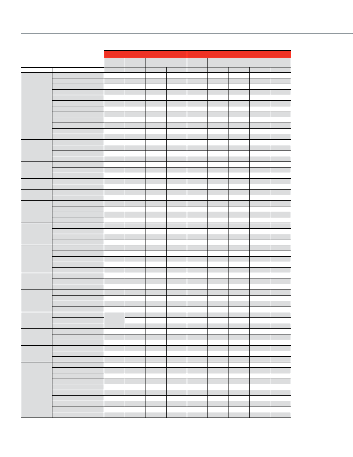
Actuator O.S. Number
Power Supply Voltage 24 Vac 24 Vac 24 Vac 24 Vac
Control 2-Position SPDT • •
4-20 mA (external 500 Ohm resistor) • •
Pneumatic Spring Range
Fail Safe Action
Reversible Operation Wiring Change • •
Stroke Timing Seconds @ 60 Hz (Drive) 125 125 125 125
Manual Override (Use valve dust cap) • • • •
Position Indicator
Electrical Connection Cable length, in. 36 36 36 36
1/2 in. flexible conduit hub • • • •
Flow
Characteristic
Equal% Stem Down
Linear Stem Up
Flow
Characteristic
A-AB Equal%,
B-AB Linear
Linear
Valve
Closes
Valve
Closes
Stem Up
Frequency 50/60 Hz 50/60 Hz 50/60 Hz 50/60 Hz
Stem Force (lb.) 40.5 67.5 40.5 67.5
0(2)-10 Vdc DIP Switch DIP Switch
DIP Switch • •
Plenum-rated Cable • • • •
Screw terminals
Valve O.S.
Number
V5862A2005
V5852A2007
V5862A2013
V5852A2015
V5862A2021
V5852A2023
V5862A2039
V5852A2031
2
V5862A2047
V5852A2049
V5862A2054
V5852A2056
V5862A2062
V5852A2064
V5862A2070
V5852A2072
V5862A3003
V5862A3011
V5862A3029
V5862A3037
V5862A3045
Valve O.S.
Number
V5863A2004
V5853A2006
V5863A2012
V5853A2014
V5863A2020
V5853A2022
V5863A2038
V5853A2030
V5863A2046
V5853A2048
V5863A1006
V5853A1008
V5863A1014
V5853A1016
V5863A2053
V5853A2055
V5863A2061
V5853A2063
V5863A3002
V5863A3010
V5863A3028
V5863A3036
V5863A3044
M6410A1029 M6410A3017 M7410F1000 M7410F3006
Power 0.7 VA 0.7 VA 1.4 VA 1.4 VA
Floating • •
Stay in Place Stay in Place Stay in Place Stay in Place
Fail Safe
• • • •
232 232
232 232
232 232
232 232
232 232
232 232
232 232
232 232
174 174
174 174
174 174
174 174
58 58
58 58
58 58
58 58
116 116
116 116
116 116
116 116
36 36
36 36
36 36
36 36
34 34
34 34
34 34
34 34
34 34
34 34
7.25 7.25
7.25 7.25
7.25 7.25
7.25 7.25
Non-Fail Safe
Close-off Pressure, psid
232 232
232 232
232 232
174 174
145 145
Close-off Pressure, psid
232 232
232 232
232 232
174 174
145 145
Page 27
Cartridge Globe Valves
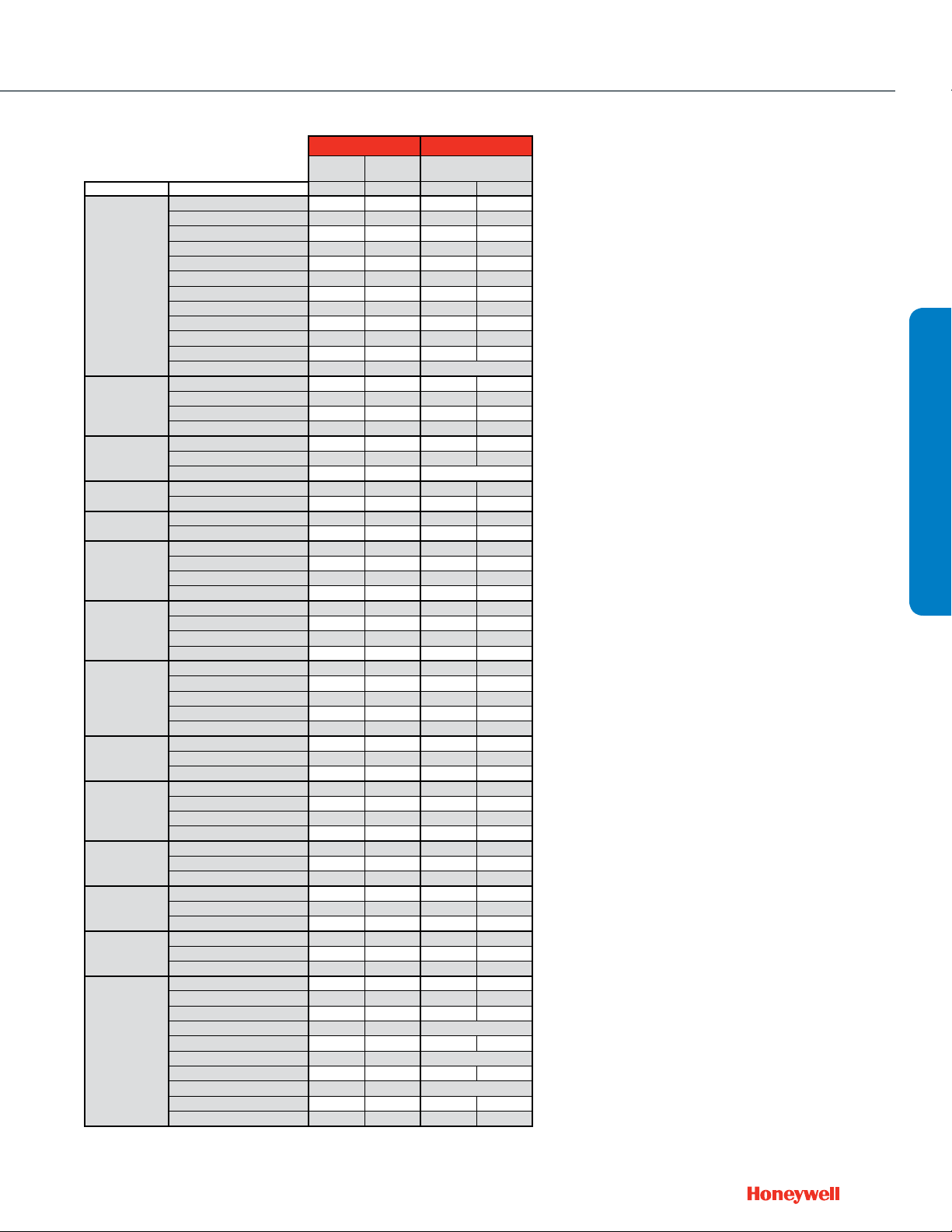
Actuator O.S. Number
Power Supply Voltage 24 Vac 24 Vac 24 Vac 24 Vac
Control 2-Position SPDT • •
4-20 mA (external 500 Ohm resistor) • •
Pneumatic Spring Range 2-5 psi 3-10 psi 8-11 psi
Fail Safe Action
Reversible Operation Wiring Change • •
Stroke Timing Seconds @ 60 Hz (Drive) 50 50 50 50
Manual Override (Use valve dust cap) • • • • • • •
Position Indicator
Electrical Connection Cable length, in.
1/2 in. flexible conduit hub • • • •
Valve Size
(inches)
1/2"
2-Way
3/4"
1"
1-1/4" f NPT 18
1-1/2" f NPT 25
Valve Size
(inches)
1/2"
3-Way
3/4"
1"
1-1/4" f NPT 18
1-1/2" f NPT 25
Notes: *20 psi for 2-way; 0 psi for 3-way
B-port Close-off of 3-way valves is the same as A-port in 2-way valves
Pipe
Connection Type
f NPT 0.19
Sweat 0.19
f NPT 0.29
Sweat 0.29
f NPT 0.47
Sweat 0.47
f NPT 0.74
Sweat 0.74
f NPT 1.2
Sweat 1.2
f NPT 1.9
Sweat 1.9
f NPT 2.9
Sweat 2.9
f NPT 4.9
Sweat 4.9
f NPT 5.5
f NPT 7.8
f NPT 11
Pipe
Connection Type
f NPT 0.29
Sweat 0.29
f NPT 0.47
Sweat 0.47
f NPT 0.74
Sweat 0.74
f NPT 1.2
Sweat 1.2
f NPT 1.9
Sweat 1.9
f NPT 2.9
Sweat 2.9
f NPT 4.9
Sweat 4.9
f NPT 2.9
Sweat 2.9
f NPT 4.9
Sweat 4.9
f NPT 5.5
f NPT 7.8
f NPT 11
3
Insert determines Cv for 1/2” and 3/4" bodies. Grouped inserts are interchangeable.
Flow
Capacity (Cv)
Flow
Capacity (Cv)
Flow
Characteristic
Equal% Stem Down
Linear Stem Up
Flow
Characteristic
A-AB Equal%,
B-AB Linear
Linear
Valve
Closes
Valve
Closes
Stem Up
M6435A1004 M6435A3000 M7435F1001 M7435F3007 MP958A1009 MP958A1017 MP958A1025
Frequency 50/60 Hz 50/60 Hz 50/60 Hz 50/60 Hz
Power 10 VA 10 VA 5 VA 5 VA
Stem Force (lb.) 40.5 90 40.5 90
Floating • •
0(2)-10 Vdc DIP Switch DIP Switch
2-way N.O.
3-way N.C.
DIP Switch • •
Fail Safe 10 10 10 10
• • • •
Plenum-rated Cable
Screw terminals • • • •
Valve O.S.
Number
V5862A2005
V5852A2007
V5862A2013
V5852A2015
V5862A2021
V5852A2023
V5862A2039
V5852A2031
2
V5862A2047
V5852A2049
V5862A2054
V5852A2056
V5862A2062
V5852A2064
V5862A2070
V5852A2072
V5862A3003
V5862A3011
V5862A3029
V5862A3037
V5862A3045
Valve O.S.
Number
V5863A2004
V5853A2006
V5863A2012
V5853A2014
V5863A2020
V5853A2022
V5863A2038
V5853A2030
V5863A2046
V5853A2048
V5863A1006
V5853A1008
V5863A1014
V5853A1016
V5863A2053
V5853A2055
V5863A2061
V5853A2063
V5863A3002
V5863A3010
V5863A3028
V5863A3036
V5863A3044
Close-off Pressure, psid
232 232 232 232 232 0902812
232 232 232 232 232 0902812
232 232 232 232 232 0902811
232 232 232 232 232 0902811
232 232 232 232 232 0902810
232 232 232 232 232 0902810
232 232 232 232 232 0902809
232 232 232 232 232 0902809
174 174 232 140 120 0902808
174 174 232 140 120 0902808
174 174 232 140 120 0902807
174 174 232 140 120 0902807
58 58 90 50 40 0902814
58 58 90 50 40 0902814
58 58 90 50 40 0902815
58 58 90 50 40 0902815
Close-off Pressure, psid
116 116 20 80 232 0902821
116 116 20 80 232 0902821
116 116 20 80 232 0902822
116 116 20 80 232 0902822
36 36 20 80 232 0902823
36 36 20 80 232 0902823
36 36 N / A 10 100 0902824
36 36 N / A 10 100 0902824
34 34 N / A 10 100 0902825
34 34 N / A 10 100 0902825
34 34 0902826
34 34 0902826
34 34 0902827
34 34 0902827
7.25 7.25 N / A N / A 35 0902818
7.25 7.25 N / A N / A 35 0902818
7.25 7.25 N / A N / A 35 0902819
7.25 7.25 N / A N / A 35 0902819
Fail Safe Pneumatic
2-way N.O.
N.C.
3-way N.C.
232 232 0903827
232 232 0903827
232 232 0903827
174 174 0903828
145 145 0903829
232 232 0903827
232 232 0903827
232 232 0903827
174 174 0903828
145 145 0903829
N.C.
2-way N.O.
3-way N.C.
2-way N.O.
3-way N.C.
A-port Close-off Pressure, psid
Full air pressure*
A-port Close-off Pressure, psid
Full air pressure*
2-way N.O.
3-way N.C.
Replacement
3
Insert
Replacement
3
Insert
ValVe Selection
27
Page 28
Control Ball Valves ½- 3"
2-Way NPT NEMA 2
Honeywell's Control Ball Valve product lines
(VBN and VBF) feature the largest Cv range in
the industry. A patented seat design allows for
lower torque actuators, while a single spring
return actuator may be used for up to a 70
psid differential pressure close-off on up to a
6" connection size.
The VBN family features a unique field
replaceable stem assembly.
Common Features
• Max static pressure 360 psi (250°F)
• Medium: Water/glycol solutions up to 50%.
• Temperature range: -22 to +250°F
• Field congurable open or closed fail-safe
position
• ANSI class IV leakage (0.01% of Cv)
VBN2 (Two-way)
• Equal % ow insert. Linear with full port.
(Largest Cv valve in each valve size is full
port), as noted
• Nickel-chrome plated brass or 316 stainless
steel ball and stem
NEED TO
PHOTOSHOP
28
Actuator Features Non-fail Safe
Actuator O.S. Number
Power Supply Voltage 24 Vac 24 Vac 24 Vac 24 Vac
Actuator Torque (lb.-in.) 44 44 44 44
Control (0)2-10 Vdc • •
4-20 mA (external 500 Ohm Resistor) • •
Fail Safe Action
Normal Position (no signal)
Actuator Stroke (degrees) 95° ± 3° 95° ± 3° 95° ± 3° 95° ± 3°
Timing (seconds) 90 90 90 90
Aux Switch 2 x SPDT Add-on SSW2 SSW2 SW2-US SW2-US
Feedback 2-10 Vdc Built In - - • •
Valve Size
2-Way
Full port ball. No flow characterizing insert.
Valve Features Trim Nickel-Plated Brass Stainless Steel Nickel-Plated Brass Stainless Steel
(inches)
1/2"
3/4"
1
"
1-1/4
1-1/2
2
"
2-1/2
3
"
"
"
"
Cv
0.38
0.68
1.3
2.6
4.7
11.7*
0.31
0.63
1.2
2.5
4.3
7.4
10.1
14.7*
29*
4.4
15.3
26
44*
54*
4.4
8.3
14.9
25
37
41*
102*
23
30
41
74*
172*
42
57
71
100
108*
210
266*
45
55
72
101
162
202*
49
63
82
124
145*
Differential Pressure (psi)
2
8
9
MN6105A1011 MN6105A1011 MN7505A2001 MN7505A2001
Frequency 50 / 60 Hz 50 / 60 Hz 50 / 60 Hz 50 / 60 Hz
Power 5 VA 5 VA 5 VA 5 VA
Floating • • • •
Two-Position SPDT • • • •
Two-Position SPST • •
Stay in Place Stay in Place Stay in Place Stay in Place
Closed Closed Closed Closed
Close-off
130
100
VBN2AB3P0A VBN2AB3S0A VBN2AB3P0B VBN2AB3S0B
VBN2AD3P0A VBN2AD3S0A VBN2AD3P0B VBN2AD3S0B
VBN2AE3P0A VBN2AE3S0A VBN2AE3P0B VBN2AE3S0B
VBN2AF3P0A VBN2AF3S0A VBN2AF3P0B VBN2AF3S0B
VBN2AG3P0A VBN2AG3S0A VBN2AG3P0B VBN2AG3S0B
VBN2AH3P0A VBN2AH3S0A VBN2AH3P0B VBN2AH3S0B
VBN2AJ3P0A VBN2AJ3S0A VBN2AJ3P0B VBN2AJ3S0B
VBN2AK3P0A VBN2AK3S0A VBN2AK3P0B VBN2AK3S0B
VBN2BB3P0A VBN2BB3S0A VBN2BB3P0B VBN2BB3S0B
VBN2BD3P0A VBN2BD3S0A VBN2BD3P0B VBN2BD3S0B
VBN2BE3P0A VBN2BE3S0A VBN2BE3P0B VBN2BE3S0B
VBN2BG3P0A VBN2BG3S0A VBN2BG3P0B VBN2BG3S0B
VBN2BH3P0A VBN2BH3S0A VBN2BH3P0B VBN2BH3S0B
VBN2BJ3P0A VBN2BJ3S0A VBN2BJ3P0B VBN2BJ3S0B
VBN2BK3P0A VBN2BK3S0A VBN2BK3P0B VBN2BK3S0B
VBN2BL3P0A VBN2BL3S0A VBN2BL3P0B VBN2BL3S0B
VBN2BM3P0A VBN2BM3S0A VBN2BM3P0B VBN2BM3S0B
VBN2CH3P0A VBN2CH3S0A VBN2CH3P0B VBN2CH3S0B
VBN2CJ3P0A VBN2CJ3S0A VBN2CJ3P0B VBN2CJ3S0B
VBN2CL3P0A VBN2CL3S0A VBN2CL3P0B VBN2CL3S0B
VBN2CM3P0A VBN2CM3S0A VBN2CM3P0B VBN2CM3S0B
VBN2CN3P0A VBN2CN3S0A VBN2CN3P0B VBN2CN3S0B
VBN2CP3P0A VBN2CP3S0A VBN2CP3P0B VBN2CP3S0B
VBN2DH3P0A VBN2DH3S0A VBN2DH3P0B VBN2DH3S0B
VBN2DJ3P0A VBN2DJ3S0A VBN2DJ3P0B VBN2DJ3S0B
VBN2DK3P0A VBN2DK3S0A VBN2DK3P0B VBN2DK3S0B
VBN2DL3P0A VBN2DL3S0A VBN2DL3P0B VBN2DL3S0B
VBN2DM3P0A VBN2DM3S0A VBN2DM3P0B VBN2DM3S0B
VBN2DN3P0A VBN2DN3S0A VBN2DN3P0B VBN2DN3S0B
VBN2DS3P0A VBN2DS3S0A VBN2DS3P0B VBN2DS3S0B
VBN2EL3P0A VBN2EL3S0A VBN2EL3P0B VBN2EL3S0B
VBN2EM3P0A VBN2EM3S0A VBN2EM3P0B VBN2EM3S0B
VBN2EN3P0A VBN2EN3S0A VBN2EN3P0B VBN2EN3S0B
VBN2ER3P0A VBN2ER3S0A VBN2ER3P0B VBN2ER3S0B
VBN2E13P0A VBN2E13S0A VBN2E13P0B VBN2E13S0B
VBN2FN3P0A VBN2FN3S0A VBN2FN3P0B VBN2FN3S0B
VBN2FP3P0A VBN2FP3S0A VBN2FP3P0B VBN2FP3S0B
VBN2FR3P0A VBN2FR3S0A VBN2FR3P0B VBN2FR3S0B
VBN2FS3P0A VBN2FS3S0A VBN2FS3P0B VBN2FS3S0B
VBN2FT3P0A VBN2FT3S0A VBN2FT3P0B VBN2FT3S0B
VBN2F13P0A VBN2F13S0A VBN2F13P0B VBN2F13S0B
VBN2F23P0A VBN2F23S0A VBN2F23P0B VBN2F23S0B
VBN2GN3P0A VBN2GN3S0A VBN2GN3P0B VBN2GN3S0B
VBN2GP3P0A VBN2GP3S0A VBN2GP3P0B VBN2GP3S0B
VBN2GR3P0A VBN2GR3S0A VBN2GR3P0B VBN2GR3S0B
VBN2GS3P0A VBN2GS3S0A VBN2GS3P0B VBN2GS3S0B
VBN2GU3P0A VBN2GU3S0A VBN2GU3P0B VBN2GU3S0B
VBN2G13P0A VBN2G13S0A VBN2G13P0B VBN2G13S0B
VBN2HN3P0A VBN2HN3S0A VBN2HN3P0B VBN2HN3S0B
VBN2HP3P0A VBN2HP3S0A VBN2HP3P0B VBN2HP3S0B
VBN2HR3P0A VBN2HR3S0A VBN2HR3P0B VBN2HR3S0B
VBN2HT3P0A VBN2HT3S0A VBN2HT3P0B VBN2HT3S0B
VBN2HU3P0A VBN2HU3S0A VBN2HU3P0B VBN2HU3S0B
Valve O.S. Number
Page 29
Actuator Features Fail Safe
Actuator O.S. Number
Power Supply Voltage 24 Vac 24 Vac 24 Vac 24 Vac
Actuator Torque (lb.-in.) 44 44 44 44
Control (0)2-10 Vdc • •
4-20 mA (external 500 Ohm Resistor) • •
Fail Safe Action
Normal Position (no signal)
Actuator Stroke (degrees) 95° ± 3° 95° ± 3° 95° ± 3° 95° ± 3°
Timing (seconds) 45 45 90 90
Aux Switch 2 x SPDT Add-on
Feedback 2-10 Vdc Built In • •
Valve Size
2-Way
Full port ball. No flow characterizing insert.
Valve Features Trim Nickel-Plated Brass Stainless Steel Nickel-Plated Brass Stainless Steel Nickel-Plated Brass Stainless Steel
(inches)
1/2"
3/4"
1
"
1-1/4
1-1/2
2
"
2-1/2
3
"
"
"
"
Cv
0.38
0.68
1.3
2
2.6
4.7
8
11.7*
0.31
0.63
1.2
2.5
4.3
7.4
10.1
14.7*
29*
4.4
9
15.3
26
44*
54*
4.4
8.3
14.9
25
37
41*
102*
23
30
41
74*
172*
42
57
71
100
108*
210
266*
45
55
72
101
162
202*
49
63
82
124
145*
Differential Pressure (psi)
Control Ball Valves ½- 3"
MS8105A1030 MS8105A1030 MS7505A2030 MS7505A2030 Valve Only Valve Only
Frequency 50 / 60 Hz 50 / 60 Hz 50 / 60 Hz 50 / 60 Hz
Power 8VA 8 VA 7.5 VA 7.5 VA
Floating • •
Two-Position SPDT • •
Two-Position SPST • • • •
Closed* Closed* Closed* Closed*
Closed* Closed* Closed* Closed*
Close-off
130
100
VBN2AB3P0C VBN2AB3S0C VBN2AB3P0D VBN2AB3S0D VBN2AB3P0X VBN2AB3S0X
VBN2AD3P0C VBN2AD3S0C VBN2AD3P0D VBN2AD3S0D VBN2AD3P0X VBN2AD3S0X
VBN2AE3P0C VBN2AE3S0C VBN2AE3P0D VBN2AE3S0D VBN2AE3P0X VBN2AE3S0X
VBN2AF3P0C VBN2AF3S0C VBN2AF3P0D VBN2AF3S0D VBN2AF3P0X VBN2AF3S0X
VBN2AG3P0C VBN2AG3S0C VBN2AG3P0D VBN2AG3S0D VBN2AG3P0X VBN2AG3S0X
VBN2AH3P0C VBN2AH3S0C VBN2AH3P0D VBN2AH3S0D VBN2AH3P0X VBN2AH3S0X
VBN2AJ3P0C VBN2AJ3S0C VBN2AJ3P0D VBN2AJ3S0D VBN2AJ3P0X VBN2AJ3S0X
VBN2AK3P0C VBN2AK3S0C VBN2AK3P0D VBN2AK3S0D VBN2AK3P0X VBN2AK3S0X
VBN2BB3P0C VBN2BB3S0C VBN2BB3P0D VBN2BB3S0D VBN2BB3P0X VBN2BB3S0X
VBN2BD3P0C VBN2BD3S0C VBN2BD3P0D VBN2BD3S0D VBN2BD3P0X VBN2BD3S0X
VBN2BE3P0C VBN2BE3S0C VBN2BE3P0D VBN2BE3S0D VBN2BE3P0X VBN2BE3S0X
VBN2BG3P0C VBN2BG3S0C VBN2BG3P0D VBN2BG3S0D VBN2BG3P0X VBN2BG3S0X
VBN2BH3P0C VBN2BH3S0C VBN2BH3P0D VBN2BH3S0D VBN2BH3P0X VBN2BH3S0X
VBN2BJ3P0C VBN2BJ3S0C VBN2BJ3P0D VBN2BJ3S0D VBN2BJ3P0X VBN2BJ3S0X
VBN2BK3P0C VBN2BK3S0C VBN2BK3P0D VBN2BK3S0D VBN2BK3P0X VBN2BK3S0X
VBN2BL3P0C VBN2BL3S0C VBN2BL3P0D VBN2BL3S0D VBN2BL3P0X VBN2BL3S0X
VBN2BM3P0C VBN2BM3S0C VBN2BM3P0D VBN2BM3S0D VBN2BM3P0X VBN2BM3S0X
VBN2CH3P0C VBN2CH3S0C VBN2CH3P0D VBN2CH3S0D VBN2CH3P0X VBN2CH3S0X
VBN2CJ3P0C VBN2CJ3S0C VBN2CJ3P0D VBN2CJ3S0D VBN2CJ3P0X VBN2CJ3S0X
VBN2CL3P0C VBN2CL3S0C VBN2CL3P0D VBN2CL3S0D VBN2CL3P0X VBN2CL3S0X
VBN2CM3P0C VBN2CM3S0C VBN2CM3P0D VBN2CM3S0D VBN2CM3P0X VBN2CM3S0X
VBN2CN3P0C VBN2CN3S0C VBN2CN3P0D VBN2CN3S0D VBN2CN3P0X VBN2CN3S0X
VBN2CP3P0C VBN2CP3S0C VBN2CP3P0D VBN2CP3S0D VBN2CP3P0X VBN2CP3S0X
VBN2DH3P0C VBN2DH3S0C VBN2DH3P0D VBN2DH3S0D VBN2DH3P0X VBN2DH3S0X
VBN2DJ3P0C VBN2DJ3S0C VBN2DJ3P0D VBN2DJ3S0D VBN2DJ3P0X VBN2DJ3S0X
VBN2DK3P0C VBN2DK3S0C VBN2DK3P0D VBN2DK3S0D VBN2DK3P0X VBN2DK3S0X
VBN2DL3P0C VBN2DL3S0C VBN2DL3P0D VBN2DL3S0D VBN2DL3P0X VBN2DL3S0X
VBN2DM3P0C VBN2DM3S0C VBN2DM3P0D VBN2DM3S0D VBN2DM3P0X VBN2DM3S0X
VBN2DN3P0C VBN2DN3S0C VBN2DN3P0D VBN2DN3S0D VBN2DN3P0X VBN2DN3S0X
VBN2DS3P0C VBN2DS3S0C VBN2DS3P0D VBN2DS3S0D VBN2DS3P0X VBN2DS3S0X
VBN2EL3P0C VBN2EL3S0C VBN2EL3P0D VBN2EL3S0D VBN2EL3P0X VBN2EL3S0X
VBN2EM3P0C VBN2EM3S0C VBN2EM3P0D VBN2EM3S0D VBN2EM3P0X VBN2EM3S0X
VBN2EN3P0C VBN2EN3S0C VBN2EN3P0D VBN2EN3S0D VBN2EN3P0X VBN2EN3S0X
VBN2ER3P0C VBN2ER3S0C VBN2ER3P0D VBN2ER3S0D VBN2ER3P0X VBN2ER3S0X
VBN2E13P0C VBN2E13S0C VBN2E13P0D VBN2E13S0D VBN2E13P0X VBN2E13S0X
VBN2FN3P0C VBN2FN3S0C VBN2FN3P0D VBN2FN3S0D VBN2FN3P0X VBN2FN3S0X
VBN2FP3P0C VBN2FP3S0C VBN2FP3P0D VBN2FP3S0D VBN2FP3P0X VBN2FP3S0X
VBN2FR3P0C VBN2FR3S0C VBN2FR3P0D VBN2FR3S0D VBN2FR3P0X VBN2FR3S0X
VBN2FS3P0C VBN2FS3S0C VBN2FS3P0D VBN2FS3S0D VBN2FS3P0X VBN2FS3S0X
VBN2FT3P0C VBN2FT3S0C VBN2FT3P0D VBN2FT3S0D VBN2FT3P0X VBN2FT3S0X
VBN2F13P0C VBN2F13S0C VBN2F13P0D VBN2F13S0D VBN2F13P0X VBN2F13S0X
VBN2F23P0C VBN2F23S0C VBN2F23P0D VBN2F23S0D VBN2F23P0X VBN2F23S0X
VBN2GN3P0C VBN2GN3S0C VBN2GN3P0D VBN2GN3S0D VBN2GN3P0X VBN2GN3S0X
VBN2GP3P0C VBN2GP3S0C VBN2GP3P0D VBN2GP3S0D VBN2GP3P0X VBN2GP3S0X
VBN2GR3P0C VBN2GR3S0C VBN2GR3P0D VBN2GR3S0D VBN2GR3P0X VBN2GR3S0X
VBN2GS3P0C VBN2GS3S0C VBN2GS3P0D VBN2GS3S0D VBN2GS3P0X VBN2GS3S0X
VBN2GU3P0C VBN2GU3S0C VBN2GU3P0D VBN2GU3S0D VBN2GU3P0X VBN2GU3S0X
VBN2G13P0C VBN2G13S0C VBN2G13P0D VBN2G13S0D VBN2G13P0X VBN2G13S0X
VBN2HN3P0C VBN2HN3S0C VBN2HN3P0D VBN2HN3S0D VBN2HN3P0X VBN2HN3S0X
VBN2HP3P0C VBN2HP3S0C VBN2HP3P0D VBN2HP3S0D VBN2HP3P0X VBN2HP3S0X
VBN2HR3P0C VBN2HR3S0C VBN2HR3P0D VBN2HR3S0D VBN2HR3P0X VBN2HR3S0X
VBN2HT3P0C VBN2HT3S0C VBN2HT3P0D VBN2HT3S0D VBN2HT3P0X VBN2HT3S0X
VBN2HU3P0C VBN2HU3S0C VBN2HU3P0D VBN2HU3S0D VBN2HU3P0X VBN2HU3S0X
Valve O.S. Number
2-Way NPT NEMA 2
VALVE SELECTION
29
Page 30
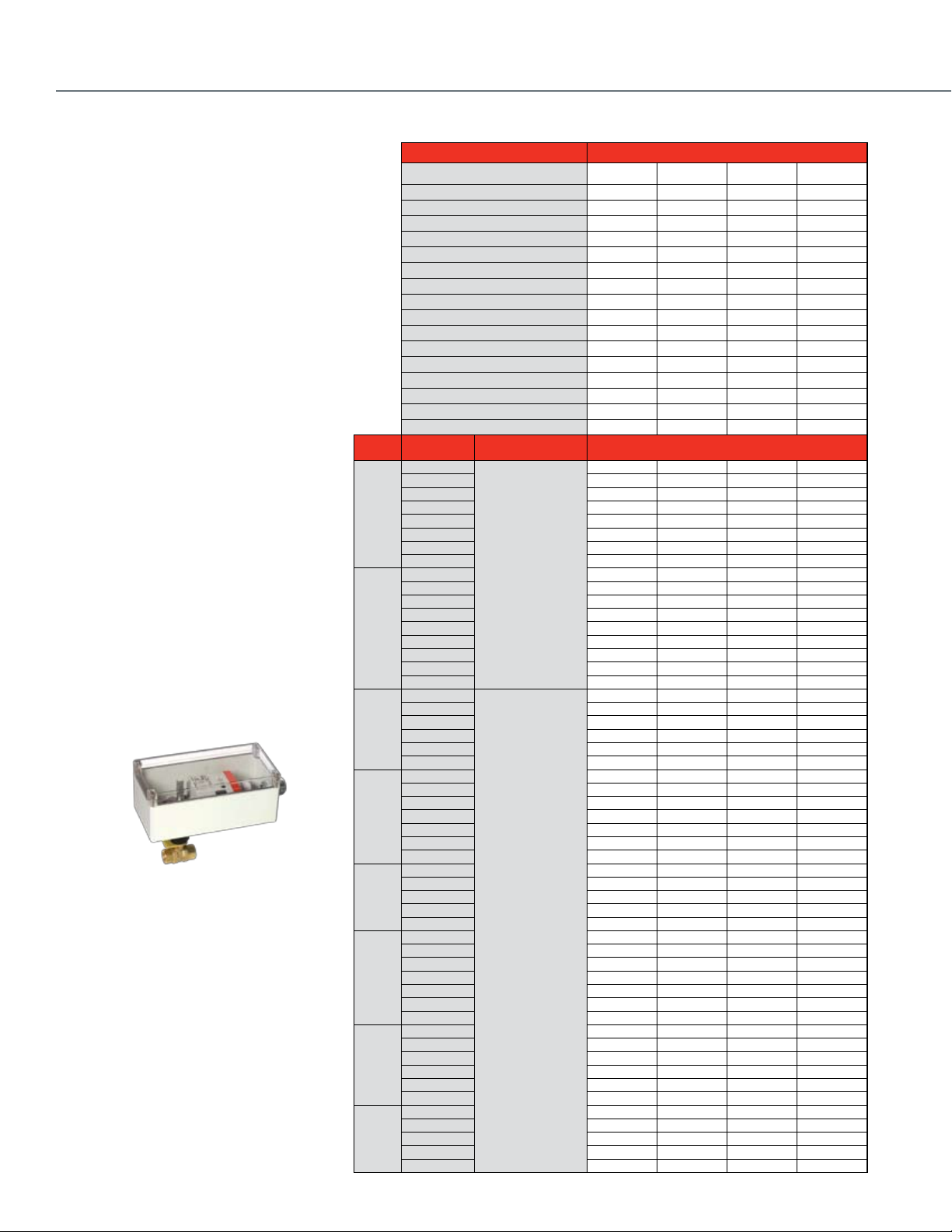
Control Ball Valves ½- 3"
2-Way NPT NEMA 3R
Common Features
• Max static pressure 360 psi (250°F)
• Medium: Water/glycol solutions up to 50%.
• Temperature range: -22 to +250°F
• Field congurable open or closed fail-safe position
• Removable handle for manual operation
• ANSI class IV leakage (0.01% of Cv)
VBN2 (Two-way):
• Equal % ow insert. Linear with full port.
(Largest Cv valve in each valve size is full port)
• Nickel-chrome plated brass or 316 stainless
steel ball and stem
Optional NEMA 3R enclosure
2-Way
Full port ball. No flow characterizing insert.
30
Valve Size
(inches)
1/2"
3/4"
1
"
1-1/4
"
1-1/2
"
2
"
2-1/2
"
3
"
Actuator Features Non-fail Safe
Actuator O.S. Number
Power Supply Voltage 24 Vac 24 Vac 24 Vac 24 Vac
Frequency 50 / 60 Hz 50 / 60 Hz 50 / 60 Hz 50 / 60 Hz
Actuator Torque (lb.-in.) 44 44 44 44
Control (0)2-10 Vdc • •
4-20 mA (external 500 Ohm Resistor) • •
Two-Position SPDT • • • •
Two-Position SPST • •
Cv
0.38
0.68
1.3
2.6
4.7
11.7*
0.31
0.63
1.2
2.5
4.3
7.4
10.1
14.7*
29*
4.4
15.3
26
44*
54*
4.4
8.3
14.9
25
37
41*
102*
23
30
41
74*
172*
42
57
71
100
108*
210
266*
45
55
72
101
162
202*
49
63
82
124
145*
Differential Pressure (psi)
2
8
9
Close-off
130
100
Fail Safe Action
Normal Position (no signal)
Actuator Stroke (degrees) 95° ± 3° 95° ± 3° 95° ± 3° 95° ± 3°
Timing (seconds) 90 90 90 90
Aux Switch 2 x SPDT Add-on SSW2 SSW2 SW2-US SW2-US
Feedback 2-10 Vdc Built In • •
Valve Features Trim Nickel-Plated Brass Stainless Steel Nickel-Plated Brass Stainless Steel
MN6105A1011 MN6105A1011 MN7505A2001 MN7505A2001
Power 5 VA 5 VA 5 VA 5 VA
Floating • • • •
Stay in Place Stay in Place Stay in Place Stay in Place
Closed Closed Closed Closed
Valve O.S. Number
VBN2AB3PRA VBN2AB3SRA VBN2AB3PRB VBN2AB3SRB
VBN2AD3PRA VBN2AD3SRA VBN2AD3PRB VBN2AD3SRB
VBN2AE3PRA VBN2AE3SRA VBN2AE3PRB VBN2AE3SRB
VBN2AF3PRA VBN2AF3SRA VBN2AF3PRB VBN2AF3SRB
VBN2AG3PRA VBN2AG3SRA VBN2AG3PRB VBN2AG3SRB
VBN2AH3PRA VBN2AH3SRA VBN2AH3PRB VBN2AH3SRB
VBN2AJ3PRA VBN2AJ3SRA VBN2AJ3PRB VBN2AJ3SRB
VBN2AK3PRA VBN2AK3SRA VBN2AK3PRB VBN2AK3SRB
VBN2BB3PRA VBN2BB3SRA VBN2BB3PRB VBN2BB3SRB
VBN2BD3PRA VBN2BD3SRA VBN2BD3PRB VBN2BD3SRB
VBN2BE3PRA VBN2BE3SRA VBN2BE3PRB VBN2BE3SRB
VBN2BG3PRA VBN2BG3SRA VBN2BG3PRB VBN2BG3SRB
VBN2BH3PRA VBN2BH3SRA VBN2BH3PRB VBN2BH3SRB
VBN2BJ3PRA VBN2BJ3SRA VBN2BJ3PRB VBN2BJ3SRB
VBN2BK3PRA VBN2BK3SRA VBN2BK3PRB VBN2BK3SRB
VBN2BL3PRA VBN2BL3SRA VBN2BL3PRB VBN2BL3SRB
VBN2BM3PRA VBN2BM3SRA VBN2BM3PRB VBN2BM3SRB
VBN2CH3PRA VBN2CH3SRA VBN2CH3PRB VBN2CH3SRB
VBN2CJ3PRA VBN2CJ3SRA VBN2CJ3PRB VBN2CJ3SRB
VBN2CL3PRA VBN2CL3SRA VBN2CL3PRB VBN2CL3SRB
VBN2CM3PRA VBN2CM3SRA VBN2CM3PRB VBN2CM3SRB
VBN2CN3PRA VBN2CN3SRA VBN2CN3PRB VBN2CN3SRB
VBN2CP3PRA VBN2CP3SRA VBN2CP3PRB VBN2CP3SRB
VBN2DH3PRA VBN2DH3SRA VBN2DH3PRB VBN2DH3SRB
VBN2DJ3PRA VBN2DJ3SRA VBN2DJ3PRB VBN2DJ3SRB
VBN2DK3PRA VBN2DK3SRA VBN2DK3PRB VBN2DK3SRB
VBN2DL3PRA VBN2DL3SRA VBN2DL3PRB VBN2DL3SRB
VBN2DM3PRA VBN2DM3SRA VBN2DM3PRB VBN2DM3SRB
VBN2DN3PRA VBN2DN3SRA VBN2DN3PRB VBN2DN3SRB
VBN2DS3PRA VBN2DS3SRA VBN2DS3PRB VBN2DS3SRB
VBN2EL3PRA VBN2EL3SRA VBN2EL3PRB VBN2EL3SRB
VBN2EM3PRA VBN2EM3SRA VBN2EM3PRB VBN2EM3SRB
VBN2EN3PRA VBN2EN3SRA VBN2EN3PRB VBN2EN3SRB
VBN2ER3PRA VBN2ER3SRA VBN2ER3PRB VBN2ER3SRB
VBN2E13PRA VBN2E13SRA VBN2E13PRB VBN2E13SRB
VBN2FN3PRA VBN2FN3SRA VBN2FN3PRB VBN2FN3SRB
VBN2FP3PRA VBN2FP3SRA VBN2FP3PRB VBN2FP3SRB
VBN2FR3PRA VBN2FR3SRA VBN2FR3PRB VBN2FR3SRB
VBN2FS3PRA VBN2FS3SRA VBN2FS3PRB VBN2FS3SRB
VBN2FT3PRA VBN2FT3SRA VBN2FT3PRB VBN2FT3SRB
VBN2F13PRA VBN2F13SRA VBN2F13PRB VBN2F13SRB
VBN2F23PRA VBN2F23SRA VBN2F23PRB VBN2F23SRB
VBN2GN3PRA VBN2GN3SRA VBN2GN3PRB VBN2GN3SRB
VBN2GP3PRA VBN2GP3SRA VBN2GP3PRB VBN2GP3SRB
VBN2GR3PRA VBN2GR3SRA VBN2GR3PRB VBN2GR3SRB
VBN2GS3PRA VBN2GS3SRA VBN2GS3PRB VBN2GS3SRB
VBN2GU3PRA VBN2GU3SRA VBN2GU3PRB VBN2GU3SRB
VBN2G13PRA VBN2G13SRA VBN2G13PRB VBN2G13SRB
VBN2HN3PRA VBN2HN3SRA VBN2HN3PRB VBN2HN3SRB
VBN2HP3PRA VBN2HP3SRA VBN2HP3PRB VBN2HP3SRB
VBN2HR3PRA VBN2HR3SRA VBN2HR3PRB VBN2HR3SRB
VBN2HT3PRA VBN2HT3SRA VBN2HT3PRB VBN2HT3SRB
VBN2HU3PRA VBN2HU3SRA VBN2HU3PRB VBN2HU3SRB
Page 31

Actuator Features Fail Safe
Actuator O.S. Number
Power Supply Voltage 24 Vac 24 Vac 24 Vac 24 Vac
Actuator Torque (lb.-in.) 44 44 44 44
Control (0)2-10 Vdc • •
4-20 mA (external 500 Ohm Resistor) • •
Fail Safe Action
Normal Position (no signal)
Actuator Stroke (degrees) 95° ± 3° 95° ± 3° 95° ± 3° 95° ± 3°
Timing (seconds) 45 45 90 90
Aux Switch 2 x SPDT Add-on
Feedback 2-10 Vdc Built In • •
Valve Size
2-Way
Full port ball. No flow characterizing insert.
Valve Features Trim Nickel-Plated Brass Stainless Steel Nickel-Plated Brass Stainless Steel Nickel-Plated Brass Stainless Steel
(inches)
1/2"
3/4"
1
"
1-1/4
1-1/2
2
"
2-1/2
3
"
"
"
"
Cv
0.38
0.68
1.3
2
2.6
4.7
8
11.7*
0.31
0.63
1.2
2.5
4.3
7.4
10.1
14.7*
29*
4.4
9
15.3
26
44*
54*
4.4
8.3
14.9
25
37
41*
102*
23
30
41
74*
172*
42
57
71
100
108*
210
266*
45
55
72
101
162
202*
49
63
82
124
145*
Differential Pressure (psi)
Control Ball Valves ½- 3"
MS8105A1030 MS8105A1030 MS7505A2030 MS7505A2030 Valve Only Valve Only
Frequency 50 / 60 Hz 50 / 60 Hz 50 / 60 Hz 50 / 60 Hz
Power 8VA 8 VA 7.5 VA 7.5 VA
Floating • •
Two-Position SPDT • •
Two-Position SPST • • • •
Closed* Closed* Closed* Closed*
Closed Closed Closed Closed
Close-off
130
100
VBN2AB3PRC VBN2AB3SRC VBN2AB3PRD VBN2AB3SRD — —
VBN2AD3PRC VBN2AD3SRC VBN2AD3PRD VBN2AD3SRD — —
VBN2AE3PRC VBN2AE3SRC VBN2AE3PRD VBN2AE3SRD — —
VBN2AF3PRC VBN2AF3SRC VBN2AF3PRD VBN2AF3SRD — —
VBN2AG3PRC VBN2AG3SRC VBN2AG3PRD VBN2AG3SRD — —
VBN2AH3PRC VBN2AH3SRC VBN2AH3PRD VBN2AH3SRD — —
VBN2AJ3PRC VBN2AJ3SRC VBN2AJ3PRD VBN2AJ3SRD — —
VBN2AK3PRC VBN2AK3SRC VBN2AK3PRD VBN2AK3SRD — —
VBN2BB3PRC VBN2BB3SRC VBN2BB3PRD VBN2BB3SRD — —
VBN2BD3PRC VBN2BD3SRC VBN2BD3PRD VBN2BD3SRD — —
VBN2BE3PRC VBN2BE3SRC VBN2BE3PRD VBN2BE3SRD — —
VBN2BG3PRC VBN2BG3SRC VBN2BG3PRD VBN2BG3SRD — —
VBN2BH3PRC VBN2BH3SRC VBN2BH3PRD VBN2BH3SRD — —
VBN2BJ3PRC VBN2BJ3SRC VBN2BJ3PRD VBN2BJ3SRD — —
VBN2BK3PRC VBN2BK3SRC VBN2BK3PRD VBN2BK3SRD — —
VBN2BL3PRC VBN2BL3SRC VBN2BL3PRD VBN2BL3SRD — —
VBN2BM3PRC VBN2BM3SRC VBN2BM3PRD VBN2BM3SRD — —
VBN2CH3PRC VBN2CH3SRC VBN2CH3PRD VBN2CH3SRD — —
VBN2CJ3PRC VBN2CJ3SRC VBN2CJ3PRD VBN2CJ3SRD — —
VBN2CL3PRC VBN2CL3SRC VBN2CL3PRD VBN2CL3SRD — —
VBN2CM3PRC VBN2CM3SRC VBN2CM3PRD VBN2CM3SRD — —
VBN2CN3PRC VBN2CN3SRC VBN2CN3PRD VBN2CN3SRD — —
VBN2CP3PRC VBN2CP3SRC VBN2CP3PRD VBN2CP3SRD — —
VBN2DH3PRC VBN2DH3SRC VBN2DH3PRD VBN2DH3SRD — —
VBN2DJ3PRC VBN2DJ3SRC VBN2DJ3PRD VBN2DJ3SRD — —
VBN2DK3PRC VBN2DK3SRC VBN2DK3PRD VBN2DK3SRD — —
VBN2DL3PRC VBN2DL3SRC VBN2DL3PRD VBN2DL3SRD — —
VBN2DM3PRC VBN2DM3SRC VBN2DM3PRD VBN2DM3SRD — —
VBN2DN3PRC VBN2DN3SRC VBN2DN3PRD VBN2DN3SRD — —
VBN2DS3PRC VBN2DS3SRC VBN2DS3PRD VBN2DS3SRD — —
VBN2EL3PRC VBN2EL3SRC VBN2EL3PRD VBN2EL3SRD — —
VBN2EM3PRC VBN2EM3SRC VBN2EM3PRD VBN2EM3SRD — —
VBN2EN3PRC VBN2EN3SRC VBN2EN3PRD VBN2EN3SRD — —
VBN2ER3PRC VBN2ER3SRC VBN2ER3PRD VBN2ER3SRD — —
VBN2E13PRC VBN2E13SRC VBN2E13PRD VBN2E13SRD — —
VBN2FN3PRC VBN2FN3SRC VBN2FN3PRD VBN2FN3SRD — —
VBN2FP3PRC VBN2FP3SRC VBN2FP3PRD VBN2FP3SRD — —
VBN2FR3PRC VBN2FR3SRC VBN2FR3PRD VBN2FR3SRD — —
VBN2FS3PRC VBN2FS3SRC VBN2FS3PRD VBN2FS3SRD — —
VBN2FT3PRC VBN2FT3SRC VBN2FT3PRD VBN2FT3SRD — —
VBN2F13PRC VBN2F13SRC VBN2F13PRD VBN2F13SRD — —
VBN2F23PRC VBN2F23SRC VBN2F23PRD VBN2F23SRD — —
VBN2GN3PRC VBN2GN3SRC VBN2GN3PRD VBN2GN3SRD — —
VBN2GP3PRC VBN2GP3SRC VBN2GP3PRD VBN2GP3SRD — —
VBN2GR3PRC VBN2GR3SRC VBN2GR3PRD VBN2GR3SRD — —
VBN2GS3PRC VBN2GS3SRC VBN2GS3PRD VBN2GS3SRD — —
VBN2GU3PRC VBN2GU3SRC VBN2GU3PRD VBN2GU3SRD — —
VBN2G13PRC VBN2G13SRC VBN2G13PRD VBN2G13SRD — —
VBN2HN3PRC VBN2HN3SRC VBN2HN3PRD VBN2HN3SRD — —
VBN2HP3PRC VBN2HP3SRC VBN2HP3PRD VBN2HP3SRD — —
VBN2HR3PRC VBN2HR3SRC VBN2HR3PRD VBN2HR3SRD — —
VBN2HT3PRC VBN2HT3SRC VBN2HT3PRD VBN2HT3SRD — —
VBN2HU3PRC VBN2HU3SRC VBN2HU3PRD VBN2HU3SRD — —
Valve O.S. Number
2-Way NPT NEMA 3R
VALVE SELECTION
31
Page 32

Control Ball Valves ½- 2½"
3-Way NPT NEMA 2
Common Features
VBN3 (Three-way):
• Equal % A to AB, linear B to AB
• Nickel-chrome plated brass
ball and stem
• Convert to 2-way by plugging
B port (plug not provided)
• Mixing or diverting control
with the same valve
Valve Size
(inches)
1/2"
3/4"
1"
3-Way
NEED TO
1-1/4"
PHOTOSHOP
1-1/2"
2"
2-1/2"
32
* Full port ball. No flow characterizing insert.
Actuator Features Non-fail Safe Fail Safe
Actuator O.S. Number
Power Supply Voltage 24 Vac 24 Vac 24 Vac 24 Vac
Frequency 50 / 60 Hz 50 / 60 Hz 50 / 60 Hz 50 / 60 Hz
Actuator Torque (lb.-in.) 44 44 44 44
Control (0)2-10 Vdc • •
4-20 mA (external 500 Ohm Resistor) • •
Two-Position SPDT • • •
Two-Position SPST • • •
Fail Safe Action
Normal Position (no signal) (field configurable)
Actuator Stroke (degrees) 95° ± 3° 95° ± 3° 95° ± 3° 95° ± 3°
Timing (seconds) 90 90 45 90
Aux Switch 2 x SPDT Add-on SSW2 SSW2
Feedback 2-10 Vdc Built In • •
Valve Features Trim Nickel-Plated Brass Nickel-Plated Brass Nickel-Plated Brass Nickel-Plated Brass Nickel-Plated Brass
(field configurable)
Cv
0.33
0.59
1
2.4
4.3
8*
0.4
0.66
1.3
2.4
3.8
7
11*
0.4
0.65
1.3
2.3
3.5
4.5
8.6
14.9
22*
31*
4.1
8.7
12.7
19.4*
27
34*
4
8.3
13.4
24
32*
61*
24
38
57*
83
109*
38
74
100*
Close-off
Differential Pressure (psi)
50
40
MN6105A1011 MN7505A2001 MS8105A1030 MS7505A2030 Valve Only
Power 5 VA 5 VA 8 VA 7.5 VA
Floating • • •
Stay in Place Stay in Place A-AB Closed A-AB Closed
Closed Closed A-AB Closed A-AB Closed
Valve O.S. Number
VBN3AB3P0A VBN3AB3P0B VBN3AB3P0C VBN3AB3P0D VBN3AB3P0X
VBN3AC3P0A VBN3AC3P0B VBN3AC3P0C VBN3AC3P0D VBN3AC3P0X
VBN3AE3P0A VBN3AE3P0B VBN3AE3P0C VBN3AE3P0D VBN3AE3P0X
VBN3AF3P0A VBN3AF3P0B VBN3AF3P0C VBN3AF3P0D VBN3AF3P0X
VBN3AH3P0A VBN3AH3P0B VBN3AH3P0C VBN3AH3P0D VBN3AH3P0X
VBN3AJ3P0A VBN3AJ3P0B VBN3AJ3P0C VBN3AJ3P0D VBN3AJ3P0X
VBN3BC3P0A VBN3BC3P0B VBN3BC3P0C VBN3BC3P0D VBN3BC3P0X
VBN3BD3P0A VBN3BD3P0B VBN3BD3P0C VBN3BD3P0D VBN3BD3P0X
VBN3BE3P0A VBN3BE3P0B VBN3BE3P0C VBN3BE3P0D VBN3BE3P0X
VBN3BF3P0A VBN3BF3P0B VBN3BF3P0C VBN3BF3P0D VBN3BF3P0X
VBN3BG3P0A VBN3BG3P0B VBN3BG3P0C VBN3BG3P0D VBN3BG3P0X
VBN3BJ3POA VBN3BJ3POB VBN3BJ3POC VBN3BJ3POD VBN3BJ3POX
VBN3BK3P0A VBN3BK3P0B VBN3BK3P0C VBN3BK3P0D VBN3BK3P0X
VBN3CC3P0A VBN3CC3P0B VBN3CC3P0C VBN3CC3P0D VBN3CC3P0X
VBN3CD3P0A VBN3CD3P0B VBN3CD3P0C VBN3CD3P0D VBN3CD3P0X
VBN3CE3P0A VBN3CE3P0B VBN3CE3P0C VBN3CE3P0D VBN3CE3P0X
VBN3CF3P0A VBN3CF3P0B VBN3CF3P0C VBN3CF3P0D VBN3CF3P0X
VBN3CG3P0A VBN3CG3P0B VBN3CG3P0C VBN3CG3P0D VBN3CG3P0X
VBN3CH3P0A VBN3CH3P0B VBN3CH3P0C VBN3CH3P0D VBN3CH3P0X
VBN3CJ3P0A VBN3CJ3P0B VBN3CJ3P0C VBN3CJ3P0D VBN3CJ3P0X
VBN3CK3P0A VBN3CK3P0B VBN3CK3P0C VBN3CK3P0D VBN3CK3P0X
VBN3CL3P0A VBN3CL3P0B VBN3CL3P0C VBN3CL3P0D VBN3CL3P0X
VBN3CM3P0A VBN3CM3P0B VBN3CM3P0C VBN3CM3P0D VBN3CM3P0X
VBN3DH3P0A VBN3DH3P0B VBN3DH3P0C VBN3DH3P0D VBN3DH3P0X
VBN3DJ3P0A VBN3DJ3P0B VBN3DJ3P0C VBN3DJ3P0D VBN3DJ3P0X
VBN3DK3P0A VBN3DK3P0B VBN3DK3P0C VBN3DK3P0D VBN3DK3P0X
VBN3DL3P0A VBN3DL3P0B VBN3DL3P0C VBN3DL3P0D VBN3DL3P0X
VBN3DM3P0A VBN3DM3P0B VBN3DM3P0C VBN3DM3P0D VBN3DM3P0X
VBN3DN3P0A VBN3DN3P0B VBN3DN3P0C VBN3DN3P0D VBN3DN3P0X
VBN3EH3P0A VBN3EH3P0B VBN3EH3P0C VBN3EH3P0D VBN3EH3P0X
VBN3EJ3P0A VBN3EJ3P0B VBN3EJ3P0C VBN3EJ3P0D VBN3EJ3P0X
VBN3EK3P0A VBN3EK3P0B VBN3EK3P0C VBN3EK3P0D VBN3EK3P0X
VBN3EL3P0A VBN3EL3P0B VBN3EL3P0C VBN3EL3P0D VBN3EL3P0X
VBN3EM3P0A VBN3EM3P0B VBN3EM3P0C VBN3EM3P0D VBN3EM3P0X
VBN3EP3P0A VBN3EP3P0B VBN3EP3P0C VBN3EP3P0D VBN3EP3P0X
VBN3FL3P0A VBN3FL3P0B VBN3FL3P0C VBN3FL3P0D VBN3FL3P0X
VBN3FN3P0A VBN3FN3P0B VBN3FN3P0C VBN3FN3P0D VBN3FN3P0X
VBN3FP3P0A VBN3FP3P0B VBN3FP3P0C VBN3FP3P0D VBN3FP3P0X
VBN3FR3P0A VBN3FR3P0B VBN3FR3P0C VBN3FR3P0D VBN3FR3P0X
VBN3FT3P0A VBN3FT3P0B VBN3FT3P0C VBN3FT3P0D VBN3FT3P0X
VBN3GN3P0A VBN3GN3P0B VBN3GN3P0C VBN3GN3P0D VBN3GN3P0X
VBN3GR3P0A VBN3GR3P0B VBN3GR3P0C VBN3GR3P0D VBN3GR3P0X
VBN3GS3P0A VBN3GS3P0B VBN3GS3P0C VBN3GS3P0D VBN3GS3P0X
Page 33

Actuator Features Non-fail Safe Fail Safe
Actuator O.S. Number
Power Supply Voltage 24 Vac 24 Vac 24 Vac 24 Vac
Actuator Torque (lb.-in.) 44 44 44 44
Control (0)2-10 Vdc • •
Fail Safe Action
Normal Position (no signal) (field configurable)
Actuator Stroke (degrees) 95° ± 3° 95° ± 3° 95° ± 3° 95° ± 3°
Timing (seconds) 90 90 45 90
Aux Switch 2 x SPDT Add-on SSW2 SSW2
Feedback 2-10 Vdc Built In • •
Valve Size
(inches)
1/2"
3/4"
3-Way
1-1/4"
1-1/2"
2-1/2"
Full port ball. No flow characterizing insert.
Valve Features Trim Nickel-Plated Brass Nickel-Plated Brass Nickel-Plated Brass Nickel-Plated Brass Nickel-Plated Brass
Cv
0.33
0.59
1
2.4
4.3
8*
0.4
0.66
1.3
2.4
3.8
7
11*
0.4
0.65
1.3
2.3
1"
2"
3.5
4.5
8.6
14.9
22*
31*
4.1
8.7
12.7
19.4*
27
34*
4
8.3
13.4
24
32*
61*
24
38
57*
83
109*
38
74
100*
Control Ball Valves ½- 2½"
3-Way NPT NEMA 3R
MN6105A1011 MN7505A2001 MS8105A1030 MS7505A2030 Valve Only
Frequency 50 / 60 Hz 50 / 60 Hz 50 / 60 Hz 50 / 60 Hz
Power 5 VA 5 VA 8 VA 7.5 VA
4-20 mA (external 500 Ohm Resistor) • •
Floating • • •
Two-Position SPDT • • •
Two-Position SPST • • •
(field configurable)
Close-off
Differential Pressure (psi)
50
40
Stay in Place Stay in Place A-AB Closed A-AB Closed
Closed Closed A-AB Closed A-AB Closed
Valve O.S. Number
VBN3AB3PRA VBN3AB3PRB VBN3AB3PRC VBN3AB3PRD —
VBN3AC3PRA VBN3AC3PRB VBN3AC3PRC VBN3AC3PRD —
VBN3AE3PRA VBN3AE3PRB VBN3AE3PRC VBN3AE3PRD —
VBN3AF3PRA VBN3AF3PRB VBN3AF3PRC VBN3AF3PRD —
VBN3AH3PRA VBN3AH3PRB VBN3AH3PRC VBN3AH3PRD —
VBN3AJ3PRA VBN3AJ3PRB VBN3AJ3PRC VBN3AJ3PRD —
VBN3BC3PRA VBN3BC3PRB VBN3BC3PRC VBN3BC3PRD —
VBN3BD3PRA VBN3BD3PRB VBN3BD3PRC VBN3BD3PRD —
VBN3BE3PRA VBN3BE3PRB VBN3BE3PRC VBN3BE3PRD —
VBN3BF3PRA VBN3BF3PRB VBN3BF3PRC VBN3BF3PRD —
VBN3BG3PRA VBN3BG3PRB VBN3BG3PRC VBN3BG3PRD —
VBN3BJ3PRA VBN3BJ3PRB VBN3BJ3PRC VBN3BJ3PRD —
VBN3BK3PRA VBN3BK3PRB VBN3BK3PRC VBN3BK3PRD —
VBN3CC3PRA VBN3CC3PRB VBN3CC3PRC VBN3CC3PRD —
VBN3CD3PRA VBN3CD3PRB VBN3CD3PRC VBN3CD3PRD —
VBN3CE3PRA VBN3CE3PRB VBN3CE3PRC VBN3CE3PRD —
VBN3CF3PRA VBN3CF3PRB VBN3CF3PRC VBN3CF3PRD —
VBN3CG3PRA VBN3CG3PRB VBN3CG3PRC VBN3CG3PRD —
VBN3CH3PRA VBN3CH3PRB VBN3CH3PRC VBN3CH3PRD —
VBN3CJ3PRA VBN3CJ3PRB VBN3CJ3PRC VBN3CJ3PRD —
VBN3CK3PRA VBN3CK3PRB VBN3CK3PRC VBN3CK3PRD —
VBN3CL3PRA VBN3CL3PRB VBN3CL3PRC VBN3CL3PRD —
VBN3CM3PRA VBN3CM3PRB VBN3CM3PRC VBN3CM3PRD —
VBN3DH3PRA VBN3DH3PRB VBN3DH3PRC VBN3DH3PRD —
VBN3DJ3PRA VBN3DJ3PRB VBN3DJ3PRC VBN3DJ3PRD —
VBN3DK3PRA VBN3DK3PRB VBN3DK3PRC VBN3DK3PRD —
VBN3DL3PRA VBN3DL3PRB VBN3DL3PRC VBN3DL3PRD —
VBN3DM3PRA VBN3DM3PRB VBN3DM3PRC VBN3DM3PRD —
VBN3DN3PRA VBN3DN3PRB VBN3DN3PRC VBN3DN3PRD —
VBN3EH3PRA VBN3EH3PRB VBN3EH3PRC VBN3EH3PRD —
VBN3EJ3PRA VBN3EJ3PRB VBN3EJ3PRC VBN3EJ3PRD —
VBN3EK3PRA VBN3EK3PRB VBN3EK3PRC VBN3EK3PRD —
VBN3EL3PRA VBN3EL3PRB VBN3EL3PRC VBN3EL3PRD —
VBN3EM3PRA VBN3EM3PRB VBN3EM3PRC VBN3EM3PRD —
VBN3EP3PRA VBN3EP3PRB VBN3EP3PRC VBN3EP3PRD —
VBN3FL3PRA VBN3FL3PRB VBN3FL3PRC VBN3FL3PRD —
VBN3FN3PRA VBN3FN3PRB VBN3FN3PRC VBN3FN3PRD —
VBN3FP3PRA VBN3FP3PRB VBN3FP3PRC VBN3FP3PRD —
VBN3FR3PRA VBN3FR3PRB VBN3FR3PRC VBN3FR3PRD —
VBN3FT3PRA VBN3FT3PRB VBN3FT3PRC VBN3FT3PRD —
VBN3GN3PRA VBN3GN3PRB VBN3GN3PRC VBN3GN3PRD —
VBN3GR3PRA VBN3GR3PRB VBN3GR3PRC VBN3GR3PRD —
VBN3GS3PRA VBN3GS3PRB VBN3GS3PRC VBN3GS3PRD —
VALVE SELECTION
33
Page 34

Flanged Control Ball Valves 4"- 6"
2-Way Flanged NEMA 2+3R
Common Features
• Maximum static pressure
240 psi (-22°F to 250°F)
• Medium: Water/glycol
solutions up to 50%
• ANSI class 125 anged
connections
• ANSI class IV leakage
(0.01% of Cv)
• Valve ball and stem 316
stainless steel
• Equal percentage ow
(linear full port)
Valve Size
(inches)
2-Way
NEW PHOTO
Actuator Features Non-fail Safe Fail Safe Valve Only
MN6110A1003
Actuator O.S. Number
Power Supply Voltage 24 Vac 24 Vac 24 Vac 24 Vac
Frequency 50 / 60 Hz 50 / 60 Hz 50 / 60 Hz 50 / 60 Hz
Power 5 / 9 VA 5 / 9 VA 30 / 40 VA 14 / 16 VA
Actuator Torque (lb.-in.) 88/300 88/300 88/175 88/175
Control (0)2-10 Vdc • •
4-20 mA (external 500 Ohm Resistor) • •
Floating • • •
Two-Position SPDT • • •
Two-Position SPST • • • •
Fail Safe Action
Normal Position (no signal) (field configurable)
Actuator Stroke (degrees) 95° 95° 95° 95°
Timing (seconds) 90 90 90 90
Aux Switch 2 x SPDT Add-on SW2-US SW2-US SW2-US SW2-US
Feedback 2-10 Vdc Built In • •
Valve Features Trim Stainless Steel Stainless Steel Stainless Steel Stainless Steel Stainless Steel
(field configurable)
Cv
Close-off
Differential Pressure (psi)
4 to 5 in.
MN6134A1003
6 in.
Stay in Place Stay in Place A-AB Closed A-AB Closed
Closed Closed Closed Closed
MN7510A2001
4 to 5 in.
MN7234A2008
6 in.
MS8110A1008
4 to 5 in.
MS8120A1007
6 in.
Valve O.S. Number
MS7510A2008
4 to 5 in.
MS7520A2007
6 in.
NEMA 2 Actuator
91
118
4"
5"
6"
152
197
254
144
185
240
309
400
208
268
346
441
577
650
70
VBF2JC1S0A VBF2JC1S0B VBF2JC1S0C VBF2JC1S0D VBF2JC1S0X
VBF2JT1S0A VBF2JT1S0B VBF2JT1S0C VBF2JT1S0D VBF2JT1S0X
VBF2JU1S0A VBF2JU1S0B VBF2JU1S0C VBF2JU1S0D VBF2JU1S0X
VBF2J11S0A VBF2J11S0B VBF2J11S0C VBF2J11S0D VBF2J11S0X
VBF2J21S0A VBF2J21S0B VBF2J21S0C VBF2J21S0D VBF2J21S0X
VBF2KU1S0A VBF2KU1S0B VBF2KU1S0C VBF2KU1S0D VBF2KU1S0X
VBF2K11S0A VBF2K11S0B VBF2K11S0C VBF2K11S0D VBF2K11S0X
VBF2K21S0A VBF2K21S0B VBF2K21S0C VBF2K21S0D VBF2K21S0X
VBF2K31S0A VBF2K31S0B VBF2K31S0C VBF2K31S0D VBF2K31S0X
VBF2K41S0A VBF2K41S0B VBF2K41S0C — VBF2K41S0X
VBF2L11S0A VBF2L11S0B VBF2L11S0C VBF2L11S0D VBF2L11S0X
VBF2L21S0A VBF2L21S0B VBF2L21S0C VBF2L21S0D VBF2L21S0X
VBF2L41S0A VBF2L41S0B VBF2L41S0C — VBF2L41S0X
VBF2L51S0A VBF2L51S0B VBF2L51S0C — VBF2L51S0X
VBF2L61S0A VBF2L61S0B VBF2L61S0C — VBF2L61S0X
VBF2L71S0A VBF2L71S0B VBF2L71S0C — VBF2L71S0X
NEMA 3R Actuator
91
118
4"
5"
6"
152
197
254
144
185
240
309
400
208
268
346
441
577
650
70
VBF2JC1SRA VBF2JC1SRB VBF2JC1SRC VBF2JC1SRD —
VBF2JT1SRA VBF2JT1SRB VBF2JT1SRC VBF2JT1SRD —
VBF2JU1SRA VBF2JU1SRB VBF2JU1SRC VBF2JU1SRD —
VBF2J11SRA VBF2J11SRB VBF2J11SRC VBF2J11SRD —
VBF2J21SRA VBF2J21SRB VBF2J21SRC VBF2J21SRD —
VBF2KU1SRA VBF2KU1SRB VBF2KU1SRC VBF2KU1SRD —
VBF2K11SRA VBF2K11SRB VBF2K11SRC VBF2K11SRD —
VBF2K21SRA VBF2K21SRB VBF2K21SRC VBF2K21SRD —
VBF2K31SRA VBF2K31SRB VBF2K31SRC VBF2K31SRD —
VBF2K41SRA VBF2K41SRB VBF2K41SRC — —
VBF2L11SRA VBF2L11SRB VBF2L11SRC VBF2L11SRD —
VBF2L21SRA VBF2L21SRB VBF2L21SRC VBF2L21SRD —
VBF2L41SRA VBF2L41SRB VBF2L41SRC — —
VBF2L51SRA VBF2L51SRB VBF2L51SRC — —
VBF2L61SRA VBF2L61SRB VBF2L61SRC — —
VBF2L71SRA VBF2L71SRB VBF2L71SRC — —
Valve Only
34
Page 35

Flanged Control Ball Valves 4"- 6"
3-Way Flanged NEMA 2+3R
Common Features
• Mixing or diverting with the
same 3-way valve
• Globe valve A-B-AB ow
pattern (side B port)
• Three-way: A-AB equal
percentage, B-AB linear
(80% of Cv on B-port)
Valve Size
(inches)
4"
5"
6"
3-Way
4"
NEW PHOTO
5"
6"
Actuator Features Non-fail Safe Fail Safe Valve Only
MN6110A1003
Actuator O.S. Number
Power Supply Voltage 24 Vac 24 Vac 24 Vac 24 Vac
Frequency 50 / 60 Hz 50 / 60 Hz 50 / 60 Hz 50 / 60 Hz
Power 5 / 9 VA 5 / 9 VA 30 / 40 VA 14 / 16 VA
Actuator Torque (lb.-in.) 88/300 88/300 88/175 88/175
Control (0)2-10 Vdc • •
4-20 mA (external 500 Ohm Resistor) • •
Floating • • •
Two-Position SPDT • • •
Two-Position SPST • • • •
Fail Safe Action
Normal Position (no signal) (field configurable)
Actuator Stroke (degrees) 95° 95° 95° 95°
Timing (seconds) 90 90 90 90
Aux Switch 2 x SPDT Add-on SW2-US SW2-US SW2-US SW2-US
Feedback 2-10 Vdc Built In • •
Valve Features Trim Stainless Steel Stainless Steel Stainless Steel Stainless Steel Stainless Steel
(field configurable)
Cv
Close-off
Differential Pressure (psi)
4 to 5 in.
MN6134A1003
6 in.
Stay in Place Stay in Place A-AB Closed A-AB Closed
A-AB Closed A-AB Closed A-AB Closed A-AB Closed
MN7510A2001
4 to 5 in.
MN7234A2008
6 in.
MS8110A1008
4 to 5 in.
MS8120A1007
6 in.
Valve O.S. Number
MS7510A2008
4 to 5 in.
MS7520A2007
6 in.
Valve Only
NEMA 2 Actuator
91
118
152
197
254
327
144
185
240
309
400
208
268
346
441
577
650
91
118
152
197
254
327
144
185
240
309
400
208
268
346
441
577
650
70
70
VBF3JS1S0A VBF3JS1S0B VBF3JS1S0C VBF3JS1S0D VBF3JS1S0X
VBF3JT1S0A VBF3JT1S0B VBF3JT1S0C VBF3JT1S0D VBF3JT1S0X
VBF3JU1S0A VBF3JU1S0B VBF3JU1S0C VBF3JU1S0D VBF3JU1S0X
VBF3J11S0A VBF3J11S0B VBF3J11S0C VBF3J11S0D VBF3J11S0X
VBF3J21S0A VBF3J21S0B VBF3J21S0C VBF3J21S0D VBF3J21S0X
VBF3J31S0A VBF3J31S0B VBF3J31S0C VBF3J31S0D VBF3J31S0X
VBF3KU1S0A VBF3KU1S0B VBF3KU1S0C VBF3KU1S0D VBF3KU1S0X
VBF3K11S0A VBF3K11S0B VBF3K11S0C VBF3K11S0D VBF3K11S0
VBF3K21S0A VBF3K21S0B VBF3K21S0C VBF3K21S0D VBF3K21S0X
VBF3K31S0A VBF3K31S0B VBF3K31S0C VBF3K31S0D VBF3K31S0X
VBF3K41S0A VBF3K41S0B VBF3K41S0C — VBF3K41S0X
VBF3L11S0A VBF3L11S0B VBF3L11S0C VBF3L11S0D VBF3L11S0X
VBF3L21S0A VBF3L21S0B VBF3L21S0C VBF3L21S0D VBF3L21S0X
VBF3L41S0A VBF3L41S0B VBF3L41S0C — VBF3L41S0X
VBF3L51S0A VBF3L51S0B VBF3L51S0C — VBF3L51S0X
VBF3L61S0A VBF3L61S0B VBF3L61S0C — VBF3L61S0X
VBF3L71S0A VBF3L71S0B VBF3L71S0C — VBF3L71S0X
NEMA 3R Actuator
VBF3JS1SRA VBF3JS1SRB VBF3JS1SRC VBF3JS1SRD —
VBF3JT1SRA VBF3JT1SRB VBF3JT1SRC VBF3JT1SRD —
VBF3JU1SRA VBF3JU1SRB VBF3JU1SRC VBF3JU1SRD —
VBF3J11SRA VBF3J11SRB VBF3J11SRC VBF3J11SRD —
VBF3J21SRA VBF3J21SRB VBF3J21SRC VBF3J21SRD —
VBF3J31SRA VBF3J31SRB VBF3J31SRC VBF3J31SRD —
VBF3KU1SRA VBF3KU1SRB VBF3KU1SRC VBF3KU1SRD —
VBF3K11SRA VBF3K11SRB VBF3K11SRC VBF3K11SRD —
VBF3K21SRA VBF3K21SRB VBF3K21SRC VBF3K21SRD —
VBF3K31SRA VBF3K31SRB VBF3K31SRC VBF3K31SRD —
VBF3K41SRA VBF3K41SRB VBF3K41SRC — —
VBF3L11SRA VBF3L11SRB VBF3L11SRC VBF3L11SRD —
VBF3L21SRA VBF3L21SRB VBF3L21SRC VBF3L21SRD —
VBF3L41SRA VBF3L41SRB VBF3L41SRC — —
VBF3L51SRA VBF3L51SRB VBF3L51SRC — —
VBF3L61SRA VBF3L61SRB VBF3L61SRC — —
VBF3L71SRA VBF3L71SRB VBF3L71SRC — —
—
VALVE SELECTION
35
Page 36

NPT Globe Valves ½- 3"
With Dedicated Valve Actuators
For more than 50 years, Honeywell Globe
Valves (V5011/13, VGF) have provided
precise control for most applications.
Globe valves provide the rangeability and
close-off needed to keep tight control
of the environment.
Valve
Size
(inches)
1/2"
3/4" 7.3 Stem down to close
3/4" 7.3 Stem up to close
2-Way
2-Way
3-Way
1" 11.7 Stem down to close
1" 11.7 Stem up to close
Straight Through
1-1/4" 18.7 Stem down to close
Water Valves
1-1/4" 18.7 Stem up to close
1-1/2" 29.3 Stem down to close
2" 46.8 Stem down to close
2-1/2" 63
3" 100 Stem down to close
1/2"
3/4" 7.3
1" 11.7
1-1/4" 18.7
Straight Through
1-1/2" 29.3
Steam Valves
2" 46.8
2-1/2" 63
3" 100
1/2" 2.9
1/2" 4.7
3/4" 7.3
1" 11.7
Mixing
1-1/4" 18.7
1-1/2" 29.3
2" 46.8
Water Valves
Max Static
Cv
Pressure
0.73
1.16 Stem down to close
1.85 Stem down to close
2.9 Stem down to close
2.9 Stem up to close
4.7 Stem down to close
4.7 Stem up to close
0.73
1.16
1.85
2.9
4.7
Water
217 psi
@ 248 F
250 psi
@ 100F
217 psi
@ 248 F
250 psi
@ 100F
217 psi
@ 248 F
Max Steam
Pressure /
Temperature
15 psi
(2-position)
100 psig /
337 F
N / A
Characteristic
Linear B-AB /
Equal % A-AB
Actuator Features Non-Fail Safe
Actuator O.S. Number
Power Supply Voltage
Actuator Stem Force (lbs.) 160 160 135 135 135 135
Control (0)2-10 Vdc Built-in •* •*
4-20 mA (external 500 Ohm Resistor) • • •
Fail Safe Action
Normal Position (no signal) (field configurable)
Actuator Stroke (inches) 63 63 60 30 60 30
Timing (seconds at 0.75" stroke)
Aux Switch 1 x SPDT Add-On
Feedback 2-10 Vdc Built-in 272630D 272630D
Flow
Equal %
Linear Stem down to close
Valve
Action
Stem down to close
Stem down to close
Stem up closes A-AB
ML7984A4009
24 Vac / 28 Vdc 24 Vac / 28 Vdc
Frequency
Two-Position SPDT
Two-Position SPST •
2 x SPDT Add-On • •
2-10 Vdc Add-On
220 Ohm Add-On
10 kOhm Add-On 200976B 200976B 200976B 200976B
Valve OS
Number
V5011N1008
V5011N1016
V5011N1024
V5011N1032
V5011N3004
V5011N1040
V5011N3012
V5011N1057
V5011N3020
V5011N1065
V5011N3038
V5011N1073
V5011N3046
V5011N1081
V5011N1099
V5011F1105
V5011F1113
V5011N2006
V5011N2014
V5011N2022
V5011N2030
V5011N2048
V5011N2055
V5011N2063
V5011N2071
V5011N2089
V5011N2097
V5011G1111
V5011G1129
V5013N1030
V5013N1048
V5013N1055
V5013N1063
V5013N1071
V5013N1089
V5013N1097
0 / 50 / 60 Hz 0 / 50 / 60 Hz
Power 12 VA 12 VA 7 VA 7 VA 6 VA 6 VA
Floating • • •
135 Ohm Stay in place Stay in place Stay in place Stay in place Stay in place Stay in place
Stem Up Stem Up Stem Up Stem Up Stem Up Stem Up
0.5 - 1 self adj 0.5 - 1 self adj 0.75 0.75 0.75 0.75
230 230 230 230 230 230
230 230 230 230 230 230
230 230 230 230 230 230
230 230 230 230 230 230
230 230 230 230 230 230
230 230 230 230 230 230
230 230 230 230 230 230
230 230 230 230 230 230
230 230 230 230 230 230
193 193 163 163 163 163
193 193 163 163 163 163
123 123 104 104 104 104
123 123 104 104 104 104
79 79 67 67 67 67
44 44 37 37 37 37
33 33 28 28 28 28
19 19 16 16 16 16
100 100 100 100 100 100
100 100 100 100 100 100
100 100 100 100 100 100
100 100 100 100 100 100
100 100 100 100 100 100
100 100 100 100 100 100
100 100 100 100 100 100
100 100 100 100 100 100
79 79 67
44 44 37 37 37 37
33 33 28 28 28 28
19 19 16 16 16 16
230 230 230 230 230 230
230 230 230 230 230 230
230 230 230 230 230 230
193 193 163 163 163 163
123 123 104 104 104 104
79 79 67 67 67 67
44 44 37 37 37 37
ML6984A4000
ML7420A3055
24 Vac 24 Vac 24 Vac 24 Vac
50 / 60 Hz 50 / 60 Hz 50 / 60 Hz 50 / 60 Hz
43196000-001 43196000-001 43196000-001 43196000-001
43191680-105 43191680-105 43191680-105 43191680-105
ML7420A3063
43191679-111 43191679-111
43191679-112 43191679-111
Close-off Pressure, psid
67 67 67
ML6420A3049
ML6420A3056
36
Page 37

Common Features
• ANSI body class 150
• Close-off pressure = maximum
differential pressure
• Maximum static water pressure (250°F):
240 psi
• Maximum steam pressure
2-way steam valves, 337°F: 100 psi
2-way water valves: 15 psi
• Stem travel: 0.75"
• Rangeability: 50:1
• Leakage < 0.05% of Cv
• Body material: Red brass, stainless
steel stem (steam valve has stainless
steel trim)
Valve
Size
(inches)
1/2"
3/4" 7.3 Stem down to close
3/4" 7.3 Stem up to close
2-Way
2-Way
3-Way
* valve is Normally Closed on loss of power
** valve is Normally Open on loss of power.
1" 11.7 Stem down to close
1" 11.7 Stem up to close
Straight Through
1-1/4" 18.7 Stem down to close
Water Valves
1-1/4" 18.7 Stem up to close
1-1/2" 29.3 Stem down to close
2" 46.8 Stem down to close
2-1/2" 63
3" 100 Stem down to close
1/2"
3/4" 7.3
1" 11.7
1-1/4" 18.7
Straight Through
1-1/2" 29.3
Steam Valves
2" 46.8
2-1/2" 63
3" 100
1/2" 2.9
1/2" 4.7
3/4" 7.3
1" 11.7
Mixing
1-1/4" 18.7
1-1/2" 29.3
2" 46.8
Water Valves
Max Static
Cv
Pressure
0.73
1.16 Stem down to close
1.85 Stem down to close
2.9 Stem down to close
2.9 Stem up to close
4.7 Stem down to close
4.7 Stem up to close
@ 248 F
0.73
1.16
1.85
2.9
4.7
@ 248 F
@ 248 F
Water
217 psi
250 psi
@ 100F
217 psi
250 psi
@ 100F
217 psi
Max Steam
Pressure /
Temperature
15 psi
(2-position)
100 psig /
337 F
N / A
Actuator Features Non-Fail Safe Fail Safe
Actuator O.S. Number
Power Supply Voltage 24 Vac 24 Vac 24 Vac 24 Vac 24 Vac 24 Vac
Actuator Stem Force (lbs.) 404 404 135 135 135 135
Control (0)2-10 Vdc •* •* •*
4-20 mA (external 500 Ohm Resistor) • • •
Fail Safe Action
Normal Position (no signal) (field configurable)
Actuator Stroke (inches) 90 90 90 90 90 90
Timing (seconds at 0.75" stroke)
Aux Switch 1 x SPDT Add-On
Feedback 2-10 Vdc Built-in
Flow
Characteristic
Equal %
Linear Stem down to close
Linear B-AB /
Equal % A-AB
Valve
Action
Stem down to close
Stem down to close
Stem up closes A-AB
NPT Globe Valves ½- 3"
With Dedicated Valve Actuators
ML7421A1032
Frequency 50 / 60 Hz 50 / 60 Hz 50 / 60 Hz 50 / 60 Hz 50 / 60 Hz 50 / 60 Hz
Power 12 VA 11 VA 12 VA 12 VA 11 VA 1 1 VA
Floating • • •
Two-Position SPDT • •
Two-Position SPST
135 Ohm Stay in place Stay in place Stem Down Stem Up Stem Down Stem Up
Stem Up Stem Up Stem Up Stem Up Stem Up Stem Up
0.75 0.75 0.75 0.75 0.75 0.75
43196000-001 43196000-001 43196000-001 43196000-001 43196000-001 43196000-001
43191680-102 43191680-102 43191680-105 43191680-105 43191680-105 43191680-105
2 x SPDT Add-On • • •
2-10 Vdc Add-On
220 Ohm Add-On
10 kOhm Add-On 200976B 200976B 200976B 200976B
Valve OS
Number
V5011N1008
V5011N1016
V5011N1024
V5011N1032
V5011N3004
V5011N1040
V5011N3012
V5011N1057
V5011N3020
V5011N1065
V5011N3038
V5011N1073
V5011N3046
V5011N1081
V5011N1099
V5011F1105
V5011F1113
V5011N2006
V5011N2014
V5011N2022
V5011N2030
V5011N2048
V5011N2055
V5011N2063
V5011N2071
V5011N2089
V5011N2097
V5011G1111
V5011G1129
V5013N1030
V5013N1048
V5013N1055
V5013N1063
V5013N1071
V5013N1089
V5013N1097
230 230 163* 163** 163* 163**
230 230 163** 163* 163** 163*
230 230 104* 104** 104* 104**
230 230 104** 104* 104** 104*
221 221 67* 67** 67* 67**
126 126 37* 37** 37* 37**
100 100 28* 28** 28* 28**
61 61 16* 16** 16* 16**
100 100 100* 100** 100* 100**
100 100 100* 100** 100* 100**
100 100 67* 67** 67* 67**
100 100 37* 37** 37* 37**
100 100 28* 28** 28* 28**
61 61 16* 16** 16* 16**
230 230 163 163 163 163
230 230 104 104 104 104
221 221 67 67 67 67
126 126 37 37 37 37
ML6421A1017
43191679-101 43191679-111
ML7425A3013
ML7425B3012
43191679-112
ML6425A3022
Close-off Pressure, psid
230* 230** 230* 230**
230* 230** 230* 230**
230* 230** 230* 230**
230* 230** 230* 230**
230** 230* 230** 230*
230* 230** 230* 230**
230* 230** 230* 230**
230* 230** 230* 230**
230** 230* 230** 230*
100* 100** 100* 100**
100* 100** 100* 100**
100* 100** 100* 100**
100* 100** 100* 100**
100* 100** 100* 100**
100* 100** 100* 100**
230 230 230 230
230 230 230 230
230 230 230 230
ML6425B3013
VALVE SELECTION
37
Page 38

NPT Globe Valves ½- 3"
With Direct Coupled Actuators and Valve Linkage
Common Features
• ANSI body class 150
• Close-Off pressure = maximum
differential pressure
• Maximum static water pressure (250°F):
240 psi
• Maximum steam pressure
2-way steam valves, 337°F: 100 psi
2-way water valves: 15 psi
• Stem travel: 0.75"
• Rangeability: 50:1
• Leakage < 0.05% of Cv
• Body material: Red brass, stainless steel
stem (steam valve has stainless steel
trim)
Q5020A1003
Required
Actuator Features Non-Fail Safe
Actuator O.S. Number
Power Supply Voltage 24 Vac 24 Vac 24 Vac 24 Vac 24 Vac 24 Vac
Actuator Torque (lb.-in.) 35 35 70 70 44 44
Linkage Stem Force (lbs.) 46 46 93 93 58 58
Control (0)2-10 Vdc • • •
4-20 mA (external 500 Ohm Resistor) • • •
Two-Position SPDT • • • •
Two-Position SPST • •
Fail Safe Action
ML7161A2008
Frequency 50 / 60 Hz 50 / 60 Hz 50 / 60 Hz 50 / 60 Hz 50 / 60 Hz 50 / 60 Hz
Power 5.4 VA 1.8 VA 5.4 VA 2.4 VA 5 VA 5 VA
Floating • • • •
Stay in Place Stay in Place Stay in Place Stay in Place Stay in Place Stay in Place
ML6161B2024
ML7174A2001
ML6174B2019
MN7505A2001
MN7505A2209
MN6105A1011
MN6105A1201
Valve
Size
(inches)
1/2"
3/4" 7.3 Stem down to close
3/4" 7.3 Stem up to close
2-Way
2-Way
3-Way
1" 11.7 Stem down to close
1" 11.7 Stem up to close
Straight Through
1-1/4" 18.7 Stem down to close
Water Valves
1-1/4" 18.7 Stem up to close
1-1/2" 29.3 Stem down to close
2" 46.8 Stem down to close
2-1/2" 63
3" 100 Stem down to close
1/2"
3/4" 7.3
1" 11.7
1-1/4" 18.7
Straight Through
1-1/2" 29.3
Steam Valves
2" 46.8
2-1/2" 63
3" 100
1/2" 2.9
1/2" 4.7
3/4" 7.3
1" 11.7
Mixing
1-1/4" 18.7
1-1/2" 29.3
2" 46.8
Water Valves
Max Static
Cv
Pressure
0.73
1.16 Stem down to close
1.85 Stem down to close
2.9 Stem down to close
2.9 Stem up to close
4.7 Stem down to close
4.7 Stem up to close
0.73
1.16
1.85
2.9
4.7
Water
217 psi
@ 248 F
250 psi
@ 100F
217 psi
@ 248 F
250 psi
@ 100F
217 psi
@ 248 F
Max Steam
Pressure /
Temperature
15 psi
(2-position)
100 psig /
337 F
N / A
Flow
Characteristic
Equal %
Linear Stem down to close
Linear B-AB /
Equal % A-AB
Normal Position (no signal) (field configurable)
Actuator Stroke (inches) 90° 90° 90° 90° 95° 95°
Timing (seconds at 0.75" stroke) 90 90 90 90 95 95
Aux Switch 2 x SPDT Built In 0 / 2 0 / 2
1 x SPDT Add-On 201052A 201052A 201052A 201052A
2 x SPDT Add-On 201052B 201052B 201052B 201052B SSW2 SSW2
Feedback (0)2-10 Vdc Built In •
500 Ohm Add-On 200976A 200976A 200976A 200976A
2 kOhm Add-On 200976B 200976B 200976B 200976B
Valve
Action
Stem down to close
Stem down to close
Stem up closes A-AB
Valve OS
Number
V5011N1008
V5011N1016
V5011N1024
V5011N1032
V5011N3004
V5011N1040
V5011N3012
V5011N1057
V5011N3020
V5011N1065
V5011N3038
V5011N1073
V5011N3046
V5011N1081
V5011N1099
V5011F1105
V5011F1113
V5011N2006
V5011N2014
V5011N2022
V5011N2030
V5011N2048
V5011N2055
V5011N2063
V5011N2071
V5011N2089
V5011N2097
V5011G1111
V5011G1129
V5013N1030
V5013N1048
V5013N1055
V5013N1063
V5013N1071
V5013N1089
V5013N1097
Stem Up/DownStem Up/Down Stem Up/Down Stem Up/Down Stem Up/DownStem Up/Down
Close-off Pressure, psid
230 230 230 230 230 230
230 230 230 230 230 230
230 230 230 230 230 230
230 230 230 230 230 230
230 230 230 230 230 230
143 143 230 230 188 188
143 143 230 230 188 188
69 69 156 156 91 91
69 69 156 156 91 91
47 47 109 109 63 63
47 47 109 109 63 63
29 29 69 69 39 39
29 29 69 69 39 39
17 17 44 44 24 24
8 8 24 24 12 12
5 5 16 16 7 7
2 2 9 9 3 3
100 100 100 100 100 100
100 100 100 100 100 100
100 100 100 100 100 100
100 100 100 100 100 100
100 100 100 100 100 100
69 69 100 100 91 91
47 47 100 100 63
29 29 69 69 39 39
17 17 44 44 24 24
8 8 24 24 12 12
5 5 16 16 7 7
2 2 9 9 3 3
230 230 230 230 230 230
143 143 230 230 188 188
69 69 156 156 91 91
47 47 109 109 63 63
29 29 69 69 39 39
17 17 44 44 24 24
8 8 24 24 12 12
63
38
Page 39

NPT Globe Valves ½- 3"
With Direct Coupled Actuators and Valve Linkage
Q5020A1003
Required
Actuator Features Non-Fail Safe
Actuator O.S. Number
MN7510A2001
Power Supply Voltage 24 Vac 24 Vac 24 Vac 24 Vac 24 Vac 24 Vac
Frequency 50 / 60 Hz 50 / 60 Hz 50 / 60 Hz 50 / 60 Hz 50 / 60 Hz 50 / 60 Hz
Power 5 VA 5 VA 6 VA 6 VA 9 VA 9 VA
Actuator Torque (lb.-in.) 88 88 175 175 300 300
Linkage Stem Force (lbs.) 117 117 234 234 402 402
Control (0)2-10 Vdc • • •
4-20 mA (external 500 Ohm Resistor) • • •
Floating • • • • •
Two-Position SPDT • • • • •
Two-Position SPST • • • • • •
Fail Safe Action
MN7510A2209
Stay in Place Stay in Place Stay in Place Stay in Place Stay in Place Stay in Place
MN6110A1003
MN6110A1201
MN7220A2007
MN7220A2205
MN6120A1002
MN6120A1200
MN7234A2008
MN6134A1003
VALVE SELECTION
Valve
Size
(inches)
1/2"
3/4" 7.3 Stem down to close
3/4" 7.3 Stem up to close
2-Way
2-Way
3-Way
1" 11.7 Stem down to close
1" 11.7 Stem up to close
Straight Through
1-1/4" 18.7 Stem down to close
Water Valves
1-1/4" 18.7 Stem up to close
1-1/2" 29.3 Stem down to close
2" 46.8 Stem down to close
2-1/2" 63
3" 100 Stem down to close
1/2"
3/4" 7.3
1" 11.7
1-1/4" 18.7
Straight Through
1-1/2" 29.3
Steam Valves
2" 46.8
2-1/2" 63
3" 100
1/2" 2.9
1/2" 4.7
3/4" 7.3
1" 11.7
Mixing
1-1/4" 18.7
1-1/2" 29.3
2" 46.8
Water Valves
Max Static
Cv
Pressure
0.73
1.16 Stem down to close
1.85 Stem down to close
2.9 Stem down to close
2.9 Stem up to close
4.7 Stem down to close
4.7 Stem up to close
@ 248 F
250 psi
@ 100F
0.73
1.16
1.85
2.9
4.7
@ 248 F
@ 100F
@ 248 F
Water
217 psi
217 psi
250 psi
217 psi
Max Steam
Pressure /
Temperature
15 psi
(2-position)
100 psig /
337 F
N / A
Flow
Characteristic
Equal %
Linear Stem down to close
Linear B-AB /
Equal % A-AB
Normal Position (no signal) (field configurable)
Actuator Stroke (inches) 95° 95° 95° 95° 95° 95°
Timing (seconds at 0.75" stroke) 95 95 95 95 95 95
Aux Switch 2 x SPDT Built In 0 / 2 0 / 2 0 / 2 0 / 2
1 x SPDT Add-On
2 x SPDT Add-On SSW2 SSW2 SW2-US SW2-US SW2-US SW2-US
Feedback (0)2-10 Vdc Built In • • •
500 Ohm Add-On
2 kOhm Add-On
Valve
Action
Stem down to close
Stem down to close
Stem up closes A-AB
Valve OS
Number
V5011N1008
V5011N1016
V5011N1024
V5011N1032
V5011N3004
V5011N1040
V5011N3012
V5011N1057
V5011N3020
V5011N1065
V5011N3038
V5011N1073
V5011N3046
V5011N1081
V5011N1099
V5011F1105
V5011F1113
V5011N2006
V5011N2014
V5011N2022
V5011N2030
V5011N2048
V5011N2055
V5011N2063
V5011N2071
V5011N2089
V5011N2097
V5011G1111
V5011G1129
V5013N1030
V5013N1048
V5013N1055
V5013N1063
V5013N1071
V5013N1089
V5013N1097
Stem Up/DownStem Up/Down Stem Up/Down Stem Up/Down Stem Up/DownStem Up/Down
Close-off Pressure, psid
230 230 230 230 230 230
230 230 230 230 230 230
230 230 230 230 230 230
230 230 230 230 230 230
230 230 230 230 230 230
230 230 230 230 230 230
230 230 230 230 230 230
192 192 230 230 230 230
192 192 230 230 230 230
135 135 230 230 230 230
135 135 230 230 230 230
85 85 168 168 230 230
85 85 168 168 230 230
55 55 113 113 180 180
30 30 63 63 103 103
19 19 42 42 74 74
11 11 26 26 45 45
100 100 100 100 100 100
100 100 100 100 100 100
100 100 100 100 100 100
100 100 100 100 100 100
100 100 100 100 100 100
100 100 100 100 100 100
100 100 100 100 100
85 85 100 100 100 100
55 55 100 100 100 100
30 30 58 58 100 100
19 19 42 42 74 74
11 11 26 26 45 45
230 230 230 230 230 230
230 230 230 230 230 230
192 192 230 230 230 230
135 135 230 230 230 230
85 85 168 168 230 230
55 55 105 105 180 180
30 30 103 103 103 103
100
39
Page 40

NPT Globe Valves ½- 3"
With Direct Coupled Spring Return Actuators and Valve Linkage
Common Features
• ANSI body class 150
• Close-Off pressure = maximum
differential pressure
• Maximum static water pressure (250°F):
240 psi
• Maximum steam pressure
2-way steam valves, 337°F: 100 psi
2-way water valves: 15 psi
• Stem travel: 0.75"
• Rangeability: 50:1
• Leakage < 0.05% of Cv
• Body material: Red brass, stainless steel
stem (steam valve has stainless steel
trim)
Valve
Size
(inches)
1/2"
3/4" 7.3 Stem down to close
3/4" 7.3 Stem up to close
2-Way
2-Way
3-Way
1" 11.7 Stem down to close
1" 11.7 Stem up to close
Straight Through
Water Valves
1-1/4" 18.7 Stem down to close
1-1/4" 18.7 Stem up to close
1-1/2" 29.3 Stem down to close
2" 46.8 Stem down to close
2-1/2" 63 250 psi @ 100F Stem down to close
3" 100 250 psi @ 100F Stem down to close
1/2"
3/4" 7.3
1" 11.7
1-1/4" 18.7
Straight Through
1-1/2" 29.3
Steam Valves
2" 46.8
2-1/2" 63 250 psi @ 100F
3" 100 250 psi @ 100F
1/2" 2.9
1/2" 4.7
3/4" 7.3
1" 11.7
Mixing
1-1/4" 18.7
1-1/2" 29.3
Water Valves
2" 46.8
Max Static
Cv
Water Pressure
0.73
1.16 Stem down to close
1.85 Stem down to close
2.9 Stem down to close
2.9 Stem up to close
4.7 Stem down to close
4.7 Stem up to close
217 psi @ 248 F
0.73
1.16
1.85
2.9
4.7
217 psi @ 248 F
217 psi @ 248 F
Max Steam
Pressure /
Temperature
15 psi
(2-position)
100 psig /
337 F
N / A
Flow
Characteristic
Equal %
Linear Stem down to close
Linear B-AB /
Equal % A-AB
Q5020A1003
Required
Actuator Features Fail Safe
Actuator O.S. Number
MS7505A2030
Power Supply Voltage 24 Vac 24 Vac 100-250 Vac 24 Vac 24 Vac
Frequency 50 / 60 Hz 50 / 60 Hz 60 Hz 50 / 60 Hz 50 / 60 Hz
Power 7.5VA 8 VA 11VA 1 4 VA 30 VA
Actuator Torque (lb.-in.) 44 44 44 88 88
Linkage Stem Force (lbs.) 58 58 58 117 117
Control (0)2-10 Vdc • •
4-20 mA (external 500 Ohm Resistor) • •
Floating • •
Two-Position SPDT • •
Two-Position SPST • • • • •
Fail Safe Action
Normal Position (no signal) (field configurable)
Actuator Stroke (inches) 95° 95° 95° 95° 95°
Timing (seconds at 0.75" stroke) 90 90 90 90 90
Aux Switch SPDT Built In 0 / 1 0 / 1 0 / 1 0 / 2 / 2 0 / 2
2 x SPDT Add-On SW2-US SW2-US
Feedback 2-10 Vdc Built In • •
Valve
Action
Stem down to close
Stem up closes A-AB
Valve OS
Number
V5011N1008
V5011N1016
V5011N1024
V5011N1032
V5011N3004
V5011N1040
V5011N3012
V5011N1057
V5011N3020
V5011N1065
V5011N3038
V5011N1073
V5011N3046
V5011N1081
V5011N1099
V5011F1105
V5011F1113
V5011N2006
V5011N2014
V5011N2022
V5011N2030
V5011N2048
V5011N2055
V5011N2063
V5011N2071
V5011N2089
V5011N2097
V5011G1111
V5011G1129
V5013N1030
V5013N1048
V5013N1055
V5013N1063
V5013N1071
V5013N1089
V5013N1097
MS7505A2130
Congurable
Open/Closed
Stem Up/Down Stem Up/Down Stem Up/Down Stem Up/Down Stem Up/Down
230 230 230 230 230
230 230 230 230 230
230 230 230 230 230
230 230 230 230 230
230 230 230 230 230
184 184 184 230 230
184 184 184 230 230
79 79 79 150 150
79 79 79 150 150
66 66 66 136 136
66 66 66 136 136
40 40 40 84 84
40 40 40 84 84
26 26 26 55 55
13 13 13 30 30
9 9 9 21 21
6 6 6 13 13
100 100 100 100 100
100 100 100 100 100
100 100 100 100 100
100 100 100 100 100
100 100 100 100 100
79 79 79 100 100
66 66 66 100 100
40 40 40 84 84
26 26 26 55 55
13 13 13 30 30
9 9 9 21 21
6 6 6 13 13
230 230 230 230 230
184 184 184 230 230
79 79 79 150 150
66 66 66 136 136
40 40 40 84 84
26 26 26 55 55
13 13 13 30 30
MS8105A1030
MS8105A1130
Congurable
Open/Closed
MS4105A1030
MS4105A1130
Congurable
Open/Closed
Close-off Pressure, psid
MS7510A2008
MS7510A2206
MS7510H2209
Congurable
Open/Closed
MS8110A1008
MS8110A1206
Congurable
Open/Closed
40
Page 41

With Direct Coupled Spring Return Actuators and Valve Linkage
Valve
Size
(inches)
1/2"
3/4" 7.3 Stem down to close
3/4" 7.3 Stem up to close
2-Way
2-Way
3-Way
1" 11.7 Stem down to close
1" 11.7 Stem up to close
Straight Through
Water Valves
1-1/4" 18.7 Stem down to close
1-1/4" 18.7 Stem up to close
1-1/2" 29.3 Stem down to close
2" 46.8 Stem down to close
2-1/2" 63 250 psi @ 100F Stem down to close
3" 100 250 psi @ 100F Stem down to close
1/2"
3/4" 7.3
1" 11.7
1-1/4" 18.7
Straight Through
1-1/2" 29.3
Steam Valves
2" 46.8
2-1/2" 63 250 psi @ 100F
3" 100 250 psi @ 100F
1/2" 2.9
1/2" 4.7
3/4" 7.3
1" 11.7
Mixing
1-1/4" 18.7
1-1/2" 29.3
Water Valves
2" 46.8
Max Static
Cv
Water Pressure
0.73
1.16 Stem down to close
1.85 Stem down to close
2.9 Stem down to close
2.9 Stem up to close
4.7 Stem down to close
4.7 Stem up to close
217 psi @ 248 F
0.73
1.16
1.85
2.9
4.7
217 psi @ 248 F
217 psi @ 248 F N / A
Max Steam
Pressure /
Temperature
15 psi
(2-position)
100 psig /
337 F
Flow
Characteristic
Equal %
Linear Stem down to close
Linear B-AB /
Equal % A-AB
NPT Globe Valves ½- 3"
Q5020A1003
Required
Actuator Features Fail Safe
Actuator O.S. Number
MS4110A1002
Power Supply Voltage 100-250 Vac 24 Vac 24 Vac 100-250 Vac
Frequency 60 Hz 50 / 60 Hz 50 / 60 Hz 60 Hz
Power 45 VA 16 VA 40 VA 6 0 VA
Actuator Torque (lb.-in.) 88 175 175 175
Linkage Stem Force (lbs.) 117 234 234 234
Control (0)2-10 Vdc •
4-20 mA (external 500 Ohm Resistor) •
Floating •
Two-Position SPDT •
Two-Position SPST • • • •
Fail Safe Action
Normal Position (no signal) (field configurable)
Actuator Stroke (inches) 95° 95° 95° 95°
Timing (seconds at 0.75" stroke) 90 90 90 90
Aux Switch SPDT Built In 0 / 2 0 / 2 / 2 0 / 2 0 / 2
2 x SPDT Add-On SW2-US SW2-US SW2-US SW2-US
Feedback 2-10 Vdc Built In •
Valve
Action
Stem down to close
Stem up closes A-AB
Valve OS
Number
V5011N1008
V5011N1016
V5011N1024
V5011N1032
V5011N3004
V5011N1040
V5011N3012
V5011N1057
V5011N3020
V5011N1065
V5011N3038
V5011N1073
V5011N3046
V5011N1081
V5011N1099
V5011F1105
V5011F1113
V5011N2006
V5011N2014
V5011N2022
V5011N2030
V5011N2048
V5011N2055
V5011N2063
V5011N2071
V5011N2089
V5011N2097
V5011G1111
V5011G1129
V5013N1030
V5013N1048
V5013N1055
V5013N1063
V5013N1071
V5013N1089
V5013N1097
MS4110A1200
Congurable
Open/Closed
Stem Up/Down Stem Up/Down Stem Up/Down Stem Up/Down
230 230 230 230
230 230 230 230
230 230 230 230
230 230 230 230
230 230 230 230
230 230 230 230
230 230 230 230
150 230 230 230
150 230 230 230
136 230 230 230
136 230 230 230
84 171 171 171
84 171 171 171
55 113 113 113
30 63 63 63
21 45 45 45
13 27 27 27
100 100 100 100
100 100 100 100
100 100 100 100
100 100 100 100
100 100 100 100
100 100 100 100
100 100 100 100
84 100 100 100
55 100 100 100
30 63 63 63
21 45 45 45
13 27 27 27
230 230 230 230
230 230 230 230
150 230 230 230
136 230 230 230
84 171 171 171
55 113 113 113
30 63 63 63
MS7520A2007
MS7520A2205
MS7520H2208
Congurable
Open/Closed
MS8120A1007
MS8120A1205
Congurable
Open/Closed
Close-off Pressure, psid
MS4120A1001
MS4120A1209
Congurable
Open/Closed
VALVE SELECTION
41
Page 42

Flanged Globe Valves 2½- 3"
With Direct Coupled Actuators and Valve Linkage
Common Features
• ANSI body class 125 or 250
• Close-off pressure = Maximum differential pressure
• Maximum static water pressure: Up to 400 psi
• Maximum steam pressure
(VGF, 2-pos or modulating): 100 psi
• Maximum steam pressure (V5011, 2-pos): 15 psi
• Stem travel: 0.75"
• Rangeability: 50:1
• Body material: Cast iron
• Body trim: Stainless steel stem, brass seat (V5011/13),
stainless steel (VGF)
Valve
Size
Cv
(inches)
63
2 1/2"
70
100
115 175 psi @ 130 F
3"
2-Way Water & Steam
Valves ANSI Class III (<
0.05% Cv) Seat Leakage
Seat Leakage
ANSI Class IV (< 0.01% Cv)
2-Way Water & Steam Valves
3-Way Water Valves
125 175 psi @ 130 F Linear
120 250 400 psi @ 130 F Equal %
2 1/2" 70
115 Pressure Balanced
115 Standard Equal %
3"
120 Pressure Balanced Linear
125 Standard Linear
120 Standard 250 400 psi @ 130 F Equal %
63 Mixing
63 Diverting 150 psi @ 240 F Constant Total Stem up closes B-AB
2 1/2"
70
100 Mixing
100 Diverting 150 psi @ 240 F Constant Total Stem up closes B-AB
120 Mixing 175 psi @ 130 F Equal % A-AB Stem up closes A-AB
3"
120 Diverting 175 psi @ 130 F Linear, Constant Total Stem up closes B-AB
115 Mixing 250 400 psi @ 130 F Equal % A-AB Stem up closes A-AB
120 Diverting 250 400 psi @ 130 F Linear, Constant Total Stem up closes B-AB
Valve
Type
Standard
Pressure Balanced
Standard Equal %
Pressure Balanced Linear
Standard Linear
Standard 250 400 psi @ 130 F Equal %
Mixing 175 psi @ 130 F Equal % A-AB Stem up closes A-AB
Diverting 175 psi @ 130 F Linear, Constant Total Stem up closes B-AB
Mixing 250 400 psi @ 130 F Equal % A-AB Stem up closes A-AB
Diverting 250 400 psi @ 130 F Linear, Constant Total Stem up closes B-AB
ANSI
Max Static
Class
Water Pressure
150 psi @ 240 F 15 psi (2-position) Equal %
125
175 psi @ 130 F
175 psi @ 130 F Linear
250 400 psi @ 130 F Equal %
150 psi @ 240 F 15 psi (2-position) Equal %
125
125 175 psi @ 130 F
125 175 psi @ 130 F
150 psi @ 240 F
125
150 psi @ 240 F Constant Total Stem up closes A-AB
125
Max Steam
Pressure /
Temperature
125 psig / 353 F
125 psig / 353 F
125 psig / 353 F
N / A
Flow
Characteristic
Equal %
Equal %
Equal %
Equal %
Constant Total Stem up closes A-AB
Q5020A1003
Required
Actuator Features Non-fail Safe
Actuator O.S. Number
ML7174A2001
Power Supply Voltage 24 Vac 24 Vac 24 Vac 24 Vac
Frequency 50 / 60 Hz 50 / 60 Hz 50 / 60 Hz 50 / 60 Hz
Power 5.4 VA 2.4 VA 5 VA 5 VA
Actuator Torque (lb.-in.) 70 70 88 88
Linkage Stem Force (lbs.) 93 93 117 117
Control (0)2-10 Vdc • •
4-20 mA (external 500 Ohm Resistor) • •
Floating • • •
Two-Position SPDT • • •
Two-Position SPST • •
Fail Safe Action
Normal Position (no signal) (field configurable)
Actuator Stroke (degrees) 90° 90° 95° 95°
Timing (seconds) 90 90 95 95
High Temperature Kit Steam Application 43196000-001 43196000-001 43196000-001 43196000-001
Aux Switch SPDT Built In 0 / 2 0 / 2
1 x SPDT Add-On 201052A 201052A
2 x SPDT Add-On 201052B 201052B SSW2 SSW2
Feedback (0)2-10 Vdc Built In •
500 Ohm Add-On 200976A 200976A
2 kOhm Add-On 200976B 200976B
Valve
Action
Stem down to close
Stem down to close
Valve OS
Number
V5011A1734
VGF21ES25
VGF21LS25
VGF22ES25
V5011A1767
VGF21ES30
VGF21LS30
VGF22ES30
VGF21EP25
VGF21ES25
VGF21LP25
VGF21LS25
VGF22ES25
VGF21EP30
VGF21ES30
VGF21LP30
VGF21LS30
VGF22ES30
V5013B1003
V5013C1001
VGF31EM25
VGF31LD25
VGF32EM25
VGF32LD25
V5013B1011
V5013C1019
VGF31EM30
VGF31LD30
VGF32EM30
VGF32LD30
Stay in Place Stay in Place Stay in Place Stay in Place
Stem Up/Down Stem Up/Down Stem Up/Down Stem Up/Down
21 21 27 27
18 18 34 34
18 18 34 34
18 18 34 34
9 9 11 11
9 9 16 16
9 9 16 16
9 9 16 16
100 100 100 100
100 100 100 100
21 21 27 27
21 21 27 27
23 23 44 44
18 18 34 34
23 23 44 44
18 18 34 34
9 9 11 11
9 9 11 11
15 15 29 29
9 9 16 16
15 15 29 29
9 9 16 16
ML6174B2019
MN7510A2001
MN7505A2209
Close-off Pressure, psid
MN6110A1003
MN6110A1201
42
Page 43

Valve
Size
Cv
(inches)
63
2 1/2"
70
100
115 175 psi @ 130 F
3"
2-Way Water & Steam
Valves ANSI Class III (<
0.05% Cv) Seat Leakage
Seat Leakage
ANSI Class IV (< 0.01% Cv)
2-Way Water & Steam Valves
3-Way Water Valves
125 175 psi @ 130 F Linear
120 250 400 psi @ 130 F Equal %
2 1/2" 70
115 Pressure Balanced
115 Standard Equal %
3"
120 Pressure Balanced Linear
125 Standard Linear
120 Standard 250 400 psi @ 130 F Equal %
63 Mixing
63 Diverting 150 psi @ 240 F Constant Total Stem up closes B-AB
2 1/2"
70
100 Mixing
100 Diverting 150 psi @ 240 F Constant Total Stem up closes B-AB
120 Mixing 175 psi @ 130 F Equal % A-AB Stem up closes A-AB
3"
120 Diverting 175 psi @ 130 F Linear, Constant Total Stem up closes B-AB
115 Mixing 250 400 psi @ 130 F Equal % A-AB Stem up closes A-AB
120 Diverting 250 400 psi @ 130 F Linear, Constant Total Stem up closes B-AB
Flanged Globe Valves 2½- 3"
With Direct Coupled Actuators and Valve Linkage
Q5020A1003
Required
Actuator Features Non-fail Safe
Actuator O.S. Number
Power Supply Voltage 24 Vac 24 Vac 24 Vac 24 Vac
Actuator Torque (lb.-in.) 175 175 300 300
Linkage Stem Force (lbs.) 234 234 402 402
Control (0)2-10 Vdc • •
4-20 mA (external 500 Ohm Resistor) • •
Fail Safe Action
Normal Position (no signal) (field configurable)
Actuator Stroke (degrees) 95° 95° 95° 95°
Timing (seconds) 95 95 95 95
High Temperature Kit Steam Application 43196000-001 43196000-001 43196000-001 43196000-001
Aux Switch SPDT Built In 0 / 2 0 / 2
Feedback (0)2-10 Vdc Built In • •
Valve
Type
Standard
Pressure Balanced
Standard Equal %
Pressure Balanced Linear
Standard Linear
Standard 250 400 psi @ 130 F Equal %
Mixing 175 psi @ 130 F Equal % A-AB Stem up closes A-AB
Diverting 175 psi @ 130 F Linear, Constant Total Stem up closes B-AB
Mixing 250 400 psi @ 130 F Equal % A-AB Stem up closes A-AB
Diverting 250 400 psi @ 130 F Linear, Constant Total Stem up closes B-AB
ANSI
Max Static
Class
Water Pressure
150 psi @ 240 F 15 psi (2-position) Equal %
125
175 psi @ 130 F
175 psi @ 130 F Linear
250 400 psi @ 130 F Equal %
150 psi @ 240 F 15 psi (2-position) Equal %
125
125 175 psi @ 130 F
125 175 psi @ 130 F
150 psi @ 240 F
125
150 psi @ 240 F Constant Total Stem up closes A-AB
125
Max Steam
Pressure /
Temperature
125 psig / 353 F
125 psig / 353 F
125 psig / 353 F
N / A
Flow
Characteristic
Equal %
Equal %
Equal %
Equal %
Constant Total Stem up closes A-AB
Valve
Action
Stem down to close
Stem down to close
MN7220A2007
Frequency 50 / 60 Hz 50 / 60 Hz 50 / 60 Hz 50 / 60 Hz
Power 6 VA 6 VA 9 VA 9 VA
Floating • • •
Two-Position SPDT • • •
Two-Position SPST • • • •
Stay in Place Stay in Place Stay in Place Stay in Place
Stem Up/Down Stem Up/Down Stem Up/Down Stem Up/Down
1 x SPDT Add-On
2 x SPDT Add-On SW2-US SW2-US SW2-US SW2-US
500 Ohm Add-On
2 kOhm Add-On
Valve OS
Number
V5011A1734
VGF21ES25
VGF21LS25
VGF22ES25
V5011A1767
VGF21ES30
VGF21LS30
VGF22ES30
VGF21EP25
VGF21ES25
VGF21LP25
VGF21LS25
VGF22ES25
VGF21EP30
VGF21ES30
VGF21LP30
VGF21LS30
VGF22ES30
V5013B1003
V5013C1001
VGF31EM25
VGF31LD25
VGF32EM25
VGF32LD25
V5013B1011
V5013C1019
VGF31EM30
VGF31LD30
VGF32EM30
VGF32LD30
52 52 88 88
52 52
52 52
52 52
24 24 42 42
26 26
26 26
26 26
175 175 175 175
175 175 175 175
175 175 175 175
175 175 175 175
52 52 88 88
52 52 88 88
66 66 97 97
52 52 97 97
66 66 97 97
52 52 97 97
24 24 42 42
24 24 42 42
44 44 65 65
26 26 65 65
44 44 65 65
26 26 65 65
MN6120A1002
MN7234A2008
Close-off Pressure, psid
77 77
77 77
77 77
38 38
38 38
38 38
MN6134A1003
VALVE SELECTION
43
Page 44

Flanged Globe Valves 2½- 3"
With Direct Coupled Spring Return Actuators and Valve Linkage
Common Features
• ANSI body class 125 or 250
• Close-off pressure = Maximum differential pressure
• Maximum static water pressure: Up to 400 psi
• Maximum steam pressure
(VGF, 2-pos or modulating): 100 psi
• Maximum steam pressure (V5011, 2-pos): 15 psi
• Stem travel: 0.75"
• Rangeability: 50:1
• Body material: Cast iron
• Body trim: Stainless steel stem, brass seat (V5011/13),
stainless steel (VGF)
Valve
Size
Cv
(inches)
63
2 1/2"
70
100
115 175 psi @ 130 F
3"
2-Way Water & Steam
Valves ANSI Class III (<
0.05% Cv) Seat Leakage
Seat Leakage
ANSI Class IV (< 0.01% Cv)
2-Way Water & Steam Valves
3-Way Water Valves
125 175 psi @ 130 F Linear
120 250 400 psi @ 130 F Equal %
2 1/2" 70
115 Pressure Balanced
115 Standard Equal %
3"
120 Pressure Balanced Linear
125 Standard Linear
120 Standard 250 400 psi @ 130 F Equal %
63 Mixing
63 Diverting 150 psi @ 240 F Constant Total Stem up closes B-AB
2 1/2"
70
100 Mixing
100 Diverting 150 psi @ 240 F Constant Total Stem up closes B-AB
120 Mixing 175 psi @ 130 F Equal % A-AB Stem up closes A-AB
3"
120 Diverting 175 psi @ 130 F Linear, Constant Total Stem up closes B-AB
115 Mixing 250 400 psi @ 130 F Equal % A-AB Stem up closes A-AB
120 Diverting 250 400 psi @ 130 F Linear, Constant Total Stem up closes B-AB
Valve
Type
Standard
Pressure Balanced
Standard Equal %
Pressure Balanced Linear
Standard Linear
Standard 250 400 psi @ 130 F Equal %
Mixing 175 psi @ 130 F Equal % A-AB Stem up closes A-AB
Diverting 175 psi @ 130 F Linear, Constant Total Stem up closes B-AB
Mixing 250 400 psi @ 130 F Equal % A-AB Stem up closes A-AB
Diverting 250 400 psi @ 130 F Linear, Constant Total Stem up closes B-AB
ANSI
Max Static
Class
Water Pressure
150 psi @ 240 F 15 psi (2-position) Equal %
125
175 psi @ 130 F
175 psi @ 130 F Linear
250 400 psi @ 130 F Equal %
150 psi @ 240 F 15 psi (2-position) Equal %
125
175 psi @ 130 F
125
125 175 psi @ 130 F
150 psi @ 240 F
125
150 psi @ 240 F Constant Total Stem up closes A-AB
125
Max Steam
Pressure /
Temperature
125 psig / 353 F
125 psig / 353 F
125 psig / 353 F
N / A
Flow
Characteristic
Equal %
Equal %
Equal %
Equal %
Constant Total Stem up closes A-AB
Q5020A1003
Required
Actuator Features Fail Safe
Actuator O.S. Number
Power Supply Voltage 24 Vac 24 Vac 100-250 Vac
Actuator Torque (lb.-in.) 88 88 88
Linkage Stem Force (lbs.) 117 117 117
Control (0)2-10 Vdc •
4-20 mA (external 500 Ohm Resistor) •
Two-Position SPDT •
Two-Position SPST • • •
Fail Safe Action
Normal Position (no signal) (field configurable)
Actuator Stroke (degrees) 95° 95° 95°
Timing (seconds) 90 90 90
High Temperature Kit Steam Application 43196000-001 43196000-001 43196000-001
Aux Switch SPDT Built In 0 / 2 / 2 0 / 2 0 / 2
Feedback (0)2-10 Vdc Built In •
Valve
Action
Stem down to close
Stem down to close
MS7510A2008
MS7510A2206
MS7510H2209
Frequency 50 / 60 Hz 50 / 60 Hz 60 Hz
Power 14 VA 3 0 VA 45VA
Floating •
Congurable
Open/Closed
Stem Up/Down Stem Up/Down Stem Up/Down
1 x SPDT Add-On
2 x SPDT Add-On SW2-US SW2-US SW2-US
500 Ohm Add-On
2 kOhm Add-On
Valve OS
Number
V5011A1734
VGF21ES25
VGF21LS25
VGF22ES25
V5011A1767
VGF21ES30
VGF21LS30
VGF22ES30
VGF21EP25
VGF21ES25
VGF21LP25
VGF21LS25
VGF22ES25
VGF21EP30
VGF21ES30
VGF21LP30
VGF21LS30
VGF22ES30
V5013B1003
V5013C1001
VGF31EM25
VGF31LD25
VGF32EM25
VGF32LD25
V5013B1011
V5013C1019
VGF31EM30
VGF31LD30
VGF32EM30
VGF32LD30
Close-off Pressure, psid
27 27 27
33 33 33
33 33 33
33 33 33
11 11 11
15 15 15
15 15 15
15 15 15
100 100 100
100 100 100
27 27 27
27 27 27
43 43 43
33 33 33
43 43 43
33 33 33
11 11 11
11 11 11
28 28 28
15 15 15
28 28 28
15 15 15
MS8110A1008
Congurable
Open/Closed
Congurable
Open/Closed
MS4110A1002
44
Page 45

Valve
Size
Cv
(inches)
63
2 1/2"
70
100
115 175 psi @ 130 F
3"
2-Way Water & Steam
Valves ANSI Class III (<
0.05% Cv) Seat Leakage
Seat Leakage
ANSI Class IV (< 0.01% Cv)
2-Way Water & Steam Valves
3-Way Water Valves
125 175 psi @ 130 F Linear
120 250 400 psi @ 130 F Equal %
2 1/2" 70
115 Pressure Balanced
115 Standard Equal %
3"
120 Pressure Balanced Linear
125 Standard Linear
120 Standard 250 400 psi @ 130 F Equal %
63 Mixing
63 Diverting 150 psi @ 240 F Constant Total Stem up closes B-AB
2 1/2"
70
100 Mixing
100 Diverting 150 psi @ 240 F Constant Total Stem up closes B-AB
120 Mixing 175 psi @ 130 F Equal % A-AB Stem up closes A-AB
3"
120 Diverting 175 psi @ 130 F Linear, Constant Total Stem up closes B-AB
115 Mixing 250 400 psi @ 130 F Equal % A-AB Stem up closes A-AB
120 Diverting 250 400 psi @ 130 F Linear, Constant Total Stem up closes B-AB
Flanged Globe Valves 2½- 3"
With Direct Coupled Spring Return Actuators and Valve Linkage
Q5020A1003
Required
Actuator Features Fail Safe
Actuator O.S. Number
Power Supply Voltage 24 Vac 24 Vac 100-250 Vac
Actuator Torque (lb.-in.) 175 175 175
Linkage Stem Force (lbs.) 234 234 234
Control (0)2-10 Vdc •
4-20 mA (external 500 Ohm Resistor) •
Fail Safe Action
Normal Position (no signal) (field configurable)
Actuator Stroke (degrees) 95° 95° 95°
Timing (seconds) 90 90 90
High Temperature Kit Steam Application 43196000-001 43196000-001 43196000-001
Aux Switch SPDT Built In 0 / 2 / 2 0 / 2 0 / 2
Feedback (0)2-10 Vdc Built In •
Valve
Type
Standard
Pressure Balanced
Standard Equal %
Pressure Balanced Linear
Standard Linear
Standard 250 400 psi @ 130 F Equal %
Mixing 175 psi @ 130 F Equal % A-AB Stem up closes A-AB
Diverting 175 psi @ 130 F Linear, Constant Total Stem up closes B-AB
Mixing 250 400 psi @ 130 F Equal % A-AB Stem up closes A-AB
Diverting 250 400 psi @ 130 F Linear, Constant Total Stem up closes B-AB
ANSI
Max Static
Class
Water Pressure
150 psi @ 240 F 15 psi (2-position) Equal %
125
175 psi @ 130 F
175 psi @ 130 F Linear
250 400 psi @ 130 F Equal %
150 psi @ 240 F 15 psi (2-position) Equal %
125
175 psi @ 130 F
125
125 175 psi @ 130 F
150 psi @ 240 F
125
150 psi @ 240 F Constant Total Stem up closes A-AB
125
Max Steam
Pressure /
Temperature
125 psig / 353 F
125 psig / 353 F
125 psig / 353 F
N / A
Flow
Characteristic
Equal %
Equal %
Equal %
Equal %
Constant Total Stem up closes A-AB
Valve
Action
Stem down to close
Stem down to close
MS7520A2007
MS7520A2205
MS7520H2208
Frequency 50 / 60 Hz 50 / 60 Hz 60 Hz
Power 1 6 VA 40 VA 60 VA
Floating •
Two-Position SPDT •
Two-Position SPST • • •
1 x SPDT Add-On
2 x SPDT Add-On SW2-US SW2-US SW2-US
500 Ohm Add-On
2 kOhm Add-On
Valve OS
Number
V5011A1734
VGF21ES25
VGF21LS25
VGF22ES25
V5011A1767
VGF21ES30
VGF21LS30
VGF22ES30
VGF21EP25
VGF21ES25
VGF21LP25
VGF21LS25
VGF22ES25
VGF21EP30
VGF21ES30
VGF21LP30
VGF21LS30
VGF22ES30
V5013B1003
V5013C1001
VGF31EM25
VGF31LD25
VGF32EM25
VGF32LD25
V5013B1011
V5013C1019
VGF31EM30
VGF31LD30
VGF32EM30
VGF32LD30
Congurable
Open/Closed
Stem Up/Down Stem Up/Down Stem Up/Down
Close-off Pressure, psid
56 56 56
71 71 71
71 71 71
71 71 71
25 25 25
35 35 35
35 35 35
35 35 35
175 175 175
175 175 175
175 175 175
175 175 175
56 56 56
56 56 56
89 89 89
71 71 71
89 89 89
71 71 71
25 25 25
25 25 25
59 59 59
35 35 35
59 59 59
35 35 35
MS8120A1007
Congurable
Open/Closed
Congurable
Open/Closed
MS4120A1001
VALVE SELECTION
45
Page 46

Threaded and Flanged Globe Valves 2"- 3"
With Tandem Direct Coupled Actuators and Valve Linkage
Common Features
• Stem travel: 0.75"
• Rangeability: 50:1
• Body material: Bronze (V5011/13N), Cast iron
• Seat Material: Bronze (V5011/13), Stainless Steel (VGF2),
Cast Iron (VGF3)
• Stem Material: Stainless Steel
Valve
Pipe
Size
Fitting
(inches)
2" f NPT 47
2" f NPT 47 150 217 psi @ 248 F 100 psig / 337 F Equal %
Flanged
f NPT 150 250 psi @ 100F 15 psi (2-position) Equal %
f NPT 150 250 psi @ 100F 100 psig / 337 F Linear
2 1/2"
Flanged 70
Flanged
f NPT 150 250 psi @ 100F 15 psi (2-position) Equal %
f NPT 150 250 psi @ 100F 100 psig / 337 F Linear
3"
2-Way Water & Steam Valves
ANSI Class III (< 0.05% Cv) Seat Leakage
ANSI Class IV
(< 0.01% Cv) Seat Leakage
2-Way Water & Steam Valves
3-Way Water Valves
*Only requires single actuator
** For high pressure steam-rated valves, close-off is the lesser of Maximum Steam Pressure or water close-off rating
Flanged 120
2 1/2"
Flanged
3"
2" f NPT 47 Mixing 150 217 psi @ 248 F
2 1/2"
Flanged
3"
Valve
Cv
Type
63
Standard
100
Pressure Balanced
Standard Equal %
Pressure Balanced Linear
70
Standard Linear
Standard 250 400 psi @ 130 F Equal %
115 Pressure Balanced
120 Standard Equal %
115 Pressure Balanced Linear
120 Standard Linear
120 Standard 250 400 psi @ 130 F Equal %
63 Mixing
63 Diverting 150 psi @ 240 F Constant Total Stem up closes B-AB
Mixing 175 psi @ 130 F Linear B-AB / Equal % A-AB Stem up closes A-AB
Diverting 175 psi @ 130 F Linear, Constant Total Stem up closes B-AB
70
Mixing 250 400 psi @ 130 F Linear B-AB / Equal % A-AB Stem up closes A-AB
Diverting 250 400 psi @ 130 F Linear, Constant Total Stem up closes B-AB
100 Mixing
100 Diverting 150 psi @ 240 F Constant Total Stem up closes B-AB
115 Mixing 175 psi @ 130 F Linear B-AB / Equal % A-AB Stem up closes A-AB
120 Diverting 175 psi @ 130 F Linear, Constant Total Stem up closes B-AB
115 Mixing 250 400 psi @ 130 F Linear B-AB / Equal % A-AB Stem up closes A-AB
120 Diverting 250 400 psi @ 130 F Linear, Constant Total Stem up closes B-AB
ANSI
Max Static
Class
Water Pressure
150 217 psi @ 248 F 15 psi (2-position) Equal %
125 150 psi @ 240 F 15 psi (2-position) Equal %
125 175 psi @ 130 F
125 175 psi @ 130 F Linear
250 400 psi @ 130 F Equal %
125 150 psi @ 250 F 15 psi (2-position) Equal %
125 175 psi @ 130 F
125 175 psi @ 130 F Linear
250 400 psi @ 130 F Equal %
125 175 psi @ 130 F
125 175 psi @ 130 F
150 psi @ 240 F Constant Total Stem up closes A-AB
125
150 psi @ 240 F Constant Total Stem up closes A-AB
125
Max Steam
Pressure /
Temperature
125 psig / 353 F
125 psig / 353 F
125 psig / 353 F
N / A
Flow
Characteristic
Equal %
Equal %
Equal %
Equal %
Linear B-AB / Equal % A-AB Stem up closes A-AB
Q5022A1001
Required
Actuator Features Non-fail Safe
Actuator O.S. Number
(Two required per linkage/valve)
Power Supply Voltage 24 Vac 24 Vac 24 Vac 24 Vac
Actuator Torque (lb.-in.) 175 175 300 300
Linkage Stem Force, Two Actuators (lbs.) 655 655 1115 1115
Control (0)2-10 Vdc • •
4-20 mA (external 500 Ohm Resistor) • •
Fail Safe Action
Normal Position (no signal) (field configurable)
Actuator Stroke (inches) 0.75 0.75 0.75 0.75
Timing (seconds) 95 95 95 95
Aux Switch 2 x SPDT Add-On SW2-US SW2-US SW2-US SW2-US
Feedback (0)2-10 Vdc Built In • •
Valve
Action
Stem down to close
Stem down to close
MN7220A2007
Frequency 60 Hz 60 Hz 60 Hz 60 Hz
Power 6 VA 6 VA 9 VA 9 VA
Floating • • • •
Two-Position SPDT • • • •
Two-Position SPST • • •
2 x SPDT Built In
Valve OS
Number
V5011N1099
V5011N2097
V5011A1734
V5011F1105
V5011G1111
VGF21ES25
VGF21LS25
VGF22ES25
V5011A1767
V5011F1113
V5011G1129
VGF21ES30
VGF21LS30
VGF22ES30
VGF21EP25
VGF21ES25
VGF21LP25
VGF21LS25
VGF22ES25
VGF21EP30
VGF21ES30
VGF21LP30
VGF21LS30
VGF22ES30
V5013N1097
V5013B1003
V5013C1001
VGF31EM50
VGF31LD50
VGF32EM50
VGF32LD50
V5013B1011
V5013C1019
VGF31EM60
VGF31LD60
VGF32EM60
VGF32LD60
Stay in
Stay in
Place
Down
Place
Stem Up/
Down
Stem Up/
Close-off Pressure, psid
162 162 240 240
100 100 100 100
130 130 225 225
130 130 225 225
100 100 100 100
110 110 190 190
110 110 190 190
110 110 190 190
66 66 115 115
65 65 115 115
65 65 100 100
55 55 94 94
55 55 94 94
55 55 94 94
175* 175* 175* 175*
74 74 152 152
175* 175* 175* 175*
74 74 152 152
74 74 152 152
175* 175* 175* 175*
36 36 75 75
175* 175* 175* 175*
36 36 75 75
36 36 75 75
162 162 240 240
130 130 225 225
130 130 225 225
141 141 240 240
110 110 190 190
141 141 240 240
110 110 190 190
65 65 115 115
65 65 115 115
94 94 160 160
110 110 190 190
94 94 160 160
110 110 190 190
MN72342008
MN6120A1002
Stay in
Place
Stem Up/
Down
Stay in
Stem Up/
Down
MN6134A1003
Place
46
Page 47

Threaded and Flanged Globe Valves 2"- 3"
With Tandem Direct Coupled Actuators and Valve Linkage
Valve
Pipe
Size
Fitting
(inches)
2" f NPT 47
2" f NPT 47 150 217 psi @ 248 F 100 psig / 337 F Equal %
Flanged
f NPT 150 250 psi @ 100F 15 psi (2-position) Equal %
f NPT 150 250 psi @ 100F 100 psig / 337 F Linear
2 1/2"
Flanged 70
Flanged
f NPT 150 250 psi @ 100F 15 psi (2-position) Equal %
f NPT 150 250 psi @ 100F 100 psig / 337 F Linear
3"
2-Way Water & Steam Valves
ANSI Class IV
2-Way Water & Steam Valves
*Only requires single actuator
** For high pressure steam-rated valves, close-off is the lesser of Maximum Steam Pressure or water close-off rating
***Q5022A linkage compatible with VGF valves with 1/4-28UNF stem thread (Manufactured after June, 2005)
Flanged 120
ANSI Class III (< 0.05% Cv) Seat Leakage
2 1/2"
Flanged
3"
(< 0.01% Cv) Seat Leakage
2" f NPT 47 Mixing 150 217 psi @ 248 F
2 1/2"
Flanged
3-Way Water Valves
3"
Valve
Cv
Type
63
Standard
100
Pressure Balanced
Standard Equal %
Pressure Balanced Linear
70
Standard Linear
Standard 250 400 psi @ 130 F Equal %
115 Pressure Balanced
120 Standard Equal %
115 Pressure Balanced Linear
120 Standard Linear
120 Standard 250 400 psi @ 130 F Equal %
63 Mixing
63 Diverting 150 psi @ 240 F Constant Total Stem up closes B-AB
Mixing 175 psi @ 130 F Linear B-AB / Equal % A-AB Stem up closes A-AB
Diverting 175 psi @ 130 F Linear, Constant Total Stem up closes B-AB
70
Mixing 250 400 psi @ 130 F Linear B-AB / Equal % A-AB Stem up closes A-AB
Diverting 250 400 psi @ 130 F Linear, Constant Total Stem up closes B-AB
100 Mixing
100 Diverting 150 psi @ 240 F Constant Total Stem up closes B-AB
115 Mixing 175 psi @ 130 F Linear B-AB / Equal % A-AB Stem up closes A-AB
120 Diverting 175 psi @ 130 F Linear, Constant Total Stem up closes B-AB
115 Mixing 250 400 psi @ 130 F Linear B-AB / Equal % A-AB Stem up closes A-AB
120 Diverting 250 400 psi @ 130 F Linear, Constant Total Stem up closes B-AB
ANSI
Max Static
Class
Water Pressure
150 217 psi @ 248 F 15 psi (2-position) Equal %
125 150 psi @ 240 F 15 psi (2-position) Equal %
125 175 psi @ 130 F
125 175 psi @ 130 F Linear
250 400 psi @ 130 F Equal %
125 150 psi @ 250 F 15 psi (2-position) Equal %
125 175 psi @ 130 F
125 175 psi @ 130 F Linear
250 400 psi @ 130 F Equal %
125 175 psi @ 130 F
125 175 psi @ 130 F
150 psi @ 240 F Constant Total Stem up closes A-AB
125
150 psi @ 240 F Constant Total Stem up closes A-AB
125
Max Steam
Pressure /
Temperature
125 psig / 353 F
125 psig / 353 F
125 psig / 353 F
N / A
Flow
Characteristic
Equal %
Equal %
Equal %
Equal %
Linear B-AB / Equal % A-AB Stem up closes A-AB
Q5022A1001
Required***
Actuator Features Fail Safe
Actuator O.S. Number
(Two required per linkage/valve)
MS7520A2007
MS7520A2205
MS8120A1007
Power Supply Voltage 24 Vac 24 Vac 100-250 Vac
Frequency 60 Hz 60 Hz 60 Hz
Power 16 VA 4 0 VA 6 0 VA
Actuator Torque (lb.-in.) 175 175 175
Linkage Stem Force, Two Actuators (lbs.) 655 655 655
Control (0)2-10 Vdc •
4-20 mA (external 500 Ohm Resistor) •
Floating •
Two-Position SPDT •
Two-Position SPST • • •
Fail Safe Action
Normal Position (no signal) (field configurable)
Actuator Stroke (inches) 0.75 0.75 0.75
Timing (seconds) 90 90 90
Aux Switch 2 x SPDT Add-On SW2-US SW2-US SW2-US
2 x SPDT Built In 0 / 2
Feedback (0)2-10 Vdc Built In •
Valve
Action
Stem down to close
Stem down to close
Valve OS
Number
V5011N1099
V5011N2097
V5011A1734
V5011F1105
V5011G1111
VGF21ES25
VGF21LS25
VGF22ES25
V5011A1767
V5011F1113
V5011G1129
VGF21ES30
VGF21LS30
VGF22ES30
VGF21EP25
VGF21ES25
VGF21LP25
VGF21LS25
VGF22ES25
VGF21EP30
VGF21ES30
VGF21LP30
VGF21LS30
VGF22ES30
V5013N1097
V5013B1003
V5013C1001
VGF31EM50
VGF31LD50
VGF32EM50
VGF32LD50
V5013B1011
V5013C1019
VGF31EM60
VGF31LD60
VGF32EM60
VGF32LD60
Congurable
Open/Closed
Stem Up/
Down
Congurable
Open/Closed
Stem Up/
Down
Close-off Pressure, psid
162 162 162
100 100 20
130 130 130
130 130 130
100 100 100
110 110 110
110 110 110
110 110 110
66 66 66
65 65 65
65 65 65
55 55 55
55 55 55
55 55 55
175* 175* 175*
74 74 74
175* 175* 175*
74 74 74
74 74 74
175* 175* 175*
36 36 36
175* 175* 175*
36 36 36
36 36 36
162 162 162
130 130 130
130 130 130
141 141 141
110 110 110
141 141 141
110 110 110
65 65 65
65 65 65
94 94 94
110 110 110
94 94 94
110 110 110
MS4120A1001
Congurable
Open/Closed
Stem Up/
Down
47
VALVE SELECTION
Page 48

Flanged Globe Valves 2½- 3"
With Dedicated Valve Actuators
Common Features
• ANSI body class 125 or 250
• Close-off pressure = Maximum differential pressure
• Maximum static water pressure: Up to 400 psi
• Maximum steam pressure (VGF, 2-pos or modulating): 100 psi
• Maximum steam pressure (V5011, 2-pos): 15 psi
• Stem travel: 0.75"
• Rangeability: 50:1
• Body material: Cast iron
• Body trim: Stainless steel stem, brass seat (V5011/13),
stainless steel (VGF)
Valve
Size
(inches)
2 1/2"
2-Way
3"
Cv) Seat Leakage
Water & Steam Valves
ANSI Class III (< 0.05%
2 1/2" 70
Seat Leakage
3"
ANSI Class IV (< 0.01% Cv)
2-Way Water & Steam Valves
2 1/2"
3-Way Water Valves
3"
*Requires 272629A adpater kit to provide upper stop for actuator torque switch
Valve
Cv
Type
63
70
Standard
100 125 150 psi @ 240 F 15 psi (2-position) Equal % V5011A1767 19 19 16 16
115 125 175 psi @ 130 F
125 125 175 psi @ 130 F Linear VGF21LS30 13* 13* 11 11
120 250 400 psi @ 130 F Equal % VGF22ES30 13* 13* 11 11
Pressure Balanced
Standard Equal % VGF21ES25
Pressure Balanced
Standard Linear VGF21LS25
Standard 250 400 psi @ 130 F Equal % VGF22ES25
115
Pressure Balanced
115 Standard Equal % VGF21ES30
120
Pressure Balanced
125 Standard Linear VGF21LS30
120 Standard 250 400 psi @ 130 F Equal % VGF22ES30
63 Mixing
63 Diverting 150 psi @ 240 F Constant Total Stem up closes B-AB V5013C1001 25 25 21 21
Mixing 175 psi @ 130 F Equal % A-AB Stem up closes A-AB VGF31EM25 34 34 29 29
Diverting 175 psi @ 130 F Linear, Constant Total Stem up closes B-AB VGF31LD25 27 27 23 23
70
Mixing 250 400 psi @ 130 F Equal % A-AB Stem up closes A-AB VGF32EM25 34 34 29 29
Diverting 250 400 psi @ 130 F Linear, Constant Total Stem up closes B-AB VGF32LD25 27 27 23 23
100 Mixing
100 Diverting 150 psi @ 240 F Constant Total Stem up closes B-AB V5013C1019 17 17 14 14
120 Mixing 175 psi @ 130 F Equal % A-AB Stem up closes A-AB VGF31EM30 22 22 19 19
120 Diverting 175 psi @ 130 F Linear, Constant Total Stem up closes B-AB VGF31LD30 13 13 11 11
115 Mixing 250 400 psi @ 130 F Equal % A-AB Stem up closes A-AB VGF32EM30 22 22 19 19
120 Diverting 250 400 psi @ 130 F Linear, Constant Total Stem up closes B-AB VGF32LD30 13 13 11 11
ANSI
Max Static
Class
Water Pressure
150 psi @ 240 F 15 psi (2-position) Equal %
125
175 psi @ 130 F
175 psi @ 130 F Linear VGF21LS25 27* 27* 23 23
250 400 psi @ 130 F Equal % VGF22ES25 27* 27* 23 23
125 175 psi @ 130 F
125 175 psi @ 130 F
150 psi @ 240 F
125
150 psi @ 240 F Constant Total Stem up closes A-AB V5013B1011 13 13 11 11
125
Max Steam
Pressure /
Temperature
125 psig / 353 F
125 psig / 353 F
125 psig / 353 F
N / A
Actuator Features Non-fail Safe
Actuator O.S. Number
ML7984A4009**
Power Supply Voltage 24 Vac / 28 Vdc 24 Vac / 28 Vdc 24 Vac 24 Vac
Frequency 0 / 50 / 60 Hz 0 / 50 / 60 Hz 50 / 60 Hz 50 / 60 Hz
Power 12 VA 1 2 VA 7 VA 7 VA
Actuator Torque (lb.-in.) 160 160 135 135
Control (0)2-10 Vdc • • •
4-20 mA (external 500 Ohm Resistor) Built-in • •
Floating •
Two-Position SPDT •
Two-Position SPST
135 Ohm •
Fail Safe Action
Normal Position (no signal) (field co nfigurable)
Actuator Stroke (inches)
Timing (seconds at 0.75" stroke) 63 63 60 30
High Temperature Kit Steam Application 43196000-001 43196000-001
Aux Switch 1 x SPDT Add-On 272630D 272630D
2 x SPDT Add-On 43191680-105 43191680-105
Feedback 2-10 Vdc Built In • •
2-10 Vdc Add-On 272630D 272630D
220 Ohm Add-On
10 kOhm Add-On
Flow
Characteristic
Equal % VGF21ES25 27* 27* 23 23
Equal % VGF21ES30 13* 13* 11 11
Equal %
Linear VGF21LP25 175 175 175 175
Equal % VGF21EP30 175 175 175 175
Linear VGF21LP30 175 175 175 175
Constant Total Stem up closes A-AB V5013B1003 27 27 23 23
Valve
Action
Stem down to close
Stem down to close
Valve OS
Number
V5011A1734 33 33 28 28
VGF21EP25 175 175 175 175
Stay in place Stay in place Stay in place Stay in place
Stem Up Stem Up Stem Up Stem Up
0.5 - 1 self adj 0.5 - 1 self adj
ML6984A4000**
Close-off Pressure, psid
ML7420A3055
0.75 0.75
ML7420A3063
48
Page 49

Valve
Size
(inches)
2 1/2"
2-Way
3"
Cv) Seat Leakage
Water & Steam Valves
ANSI Class III (< 0.05%
2 1/2" 70
Seat Leakage
3"
ANSI Class IV (< 0.01% Cv)
2-Way Water & Steam Valves
2 1/2"
3-Way Water Valves
3"
Flanged Globe Valves 2½- 3"
With Dedicated Valve Actuators
Actuator Features Non-fail Safe
Actuator O.S. Number
ML6420A3049
Power Supply Voltage 24 Vac 24 Vac 24 Vac 24 Vac
Frequency 50 / 60 Hz 50 / 60 Hz 50 / 60 Hz 50 / 60 Hz
Power 6 VA 6 VA 12 VA 1 1 VA
Actuator Torque (lb.-in.) 135 135 404 404
Control (0)2-10 Vdc •
4-20 mA (external 500 Ohm Resistor) •
Floating • • •
Two-Position SPDT • • •
Two-Position SPST
135 Ohm
Fail Safe Action
Normal Position (no signal) (field co nfigurable)
Actuator Stroke (inches) 0.75 0.75 0.75 0.75
Timing (seconds at 0.75" stroke) 60 30 90 90
High Temperature Kit Steam Application 43196000-001 43196000-001 43196000-001 43196000-001
Aux Switch 1 x SPDT Add-On
2 x SPDT Add-On 43191680-105 43191680-105 43191680-102 43191680-102
Feedback 2-10 Vdc Built In •
2-10 Vdc Add-On
220 Ohm Add-On 43191679-111 43191679-111 43191679-101
10 kOhm Add-On 43191679-112 43191679-111
Valve
Cv
Type
63
70
Standard
100 125 150 psi @ 240 F 15 psi (2-position) Equal % V5011A1767 16 16 53 53
115 125 175 psi @ 130 F
125 125 175 psi @ 130 F Linear VGF21LS30 11 11
120 250 400 psi @ 130 F Equal %
Pressure Balanced
Standard Equal % VGF21ES25 69 69
Pressure Balanced
Standard Linear VGF21LS25 69 69
Standard 250 400 psi @ 130 F Equal % VGF22ES25 69 69
115
Pressure Balanced
115 Standard Equal %
120
Pressure Balanced
125 Standard Linear VGF21LS30 34 34
120 Standard 250 400 psi @ 130 F Equal %
63 Mixing
63 Diverting 150 psi @ 240 F Constant Total Stem up closes B-AB V5013C1001 21 21 77 77
Mixing 175 psi @ 130 F Equal % A-AB Stem up closes A-AB
Diverting 175 psi @ 130 F Linear, Constant Total Stem up closes B-AB
70
Mixing 250 400 psi @ 130 F Equal % A-AB Stem up closes A-AB VGF32EM25 29 29 87 87
Diverting 250 400 psi @ 130 F Linear, Constant Total Stem up closes B-AB VGF32LD25 23 23 69 69
100 Mixing
100 Diverting 150 psi @ 240 F Constant Total Stem up closes B-AB V5013C1019 14 14 53 53
120 Mixing 175 psi @ 130 F Equal % A-AB Stem up closes A-AB VGF31EM30 19 19 58 58
120 Diverting 175 psi @ 130 F Linear, Constant Total Stem up closes B-AB VGF31LD30 11 11 34 34
115 Mixing 250 400 psi @ 130 F Equal % A-AB Stem up closes A-AB VGF32EM30 19 19 58 58
120 Diverting 250 400 psi @ 130 F Linear, Constant Total Stem up closes B-AB VGF32LD30 11 11 34 34
ANSI
Max Static
Class
Water Pressure
150 psi @ 240 F 15 psi (2-position) Equal %
125
175 psi @ 130 F
175 psi @ 130 F Linear VGF21LS25 23 23
250 400 psi @ 130 F Equal % VGF22ES25 23 23
125 175 psi @ 130 F
125 175 psi @ 130 F
150 psi @ 240 F
125
150 psi @ 240 F Constant Total Stem up closes A-AB V5013B1011 11 11 53 53
125
Max Steam
Pressure /
Temperature
125 psig / 353 F
125 psig / 353 F
125 psig / 353 F
N / A
Flow
Characteristic
Equal % VGF21ES25 23 23
Equal % VGF21ES30 11 11
Equal %
Linear VGF21LP25 175 175 175 175
Equal % VGF21EP30 175 175 175 175
Linear
Constant Total Stem up closes A-AB
Valve
Action
Stem down to close
Stem down to close
Valve OS
Number
V5011A1734 28 28 77 77
VGF22ES30 11 11
VGF21EP25 175 175 175 175
VGF21ES30 34 34
VGF21LP30 175 175 175 175
VGF22ES30 34 34
V5013B1003 23 23 77 77
VGF31EM25 29 29 87 87
VGF31LD25 23 23 69 69
Stay in place Stay in place Stay in place Stay in place
Stem Up Stem Up Stem Up Stem Up
ML6420A3056
ML7421A1032
Close-off Pressure, psid
ML6421A1017
VALVE SELECTION
49
Page 50

Flanged Globe Valves 2½- 3"
With Dedicated Valve Actuators
Common Features
• ANSI body class 125 or 250
• Close-off pressure = Maximum differential pressure
• Maximum static water pressure: Up to 400 psi
• Maximum steam pressure (VGF, 2-pos or modulating): 100 psi
• Maximum steam pressure (V5011, 2-pos): 15 psi
• Stem travel: 0.75"
• Rangeability: 50:1
• Body material: Cast iron
• Body trim: Stainless steel stem, brass seat (V5011/13),
stainless steel (VGF)
Valve
Size
(inches)
2 1/2"
2-Way
3"
Cv) Seat Leakage
Water & Steam Valves
ANSI Class III (< 0.05%
2 1/2" 70
Seat Leakage
3"
ANSI Class IV (< 0.01% Cv)
2-Way Water & Steam Valves
2 1/2"
3-Way Water Valves
3"
Valve
Cv
Type
63
70
Standard
100 125 150 psi @ 240 F 15 psi (2-position) Equal % V5011A1767 16 16 16 16
115 125 175 psi @ 130 F
125 125 175 psi @ 130 F Linear VGF21LS30 11 11 11 11
120 250 400 psi @ 130 F Equal %
Pressure Balanced
Standard Equal % VGF21ES25
Pressure Balanced
Standard Linear VGF21LS25
Standard 250 400 psi @ 130 F Equal % VGF22ES25 23 23 23 23
115
Pressure Balanced
115 Standard Equal %
120
Pressure Balanced
125 Standard Linear VGF21LS30
120 Standard 250 400 psi @ 130 F Equal %
63 Mixing
63 Diverting 150 psi @ 240 F Constant Total Stem up closes B-AB V5013C1001 21 21 21 21
Mixing 175 psi @ 130 F Equal % A-AB Stem up closes A-AB
Diverting 175 psi @ 130 F Linear, Constant Total Stem up closes B-AB
70
Mixing 250 400 psi @ 130 F Equal % A-AB Stem up closes A-AB VGF32EM25 29 29 29 29
Diverting 250 400 psi @ 130 F Linear, Constant Total Stem up closes B-AB VGF32LD25 23 23 23 23
100 Mixing
100 Diverting 150 psi @ 240 F Constant Total Stem up closes B-AB V5013C1019 14 14 14 14
120 Mixing 175 psi @ 130 F Equal % A-AB Stem up closes A-AB VGF31EM30 19 19 19 19
120 Diverting 175 psi @ 130 F Linear, Constant Total Stem up closes B-AB VGF31LD30 11 11 11 11
115 Mixing 250 400 psi @ 130 F Equal % A-AB Stem up closes A-AB VGF32EM30 19 19 19 19
120 Diverting 250 400 psi @ 130 F Linear, Constant Total Stem up closes B-AB VGF32LD30 11 11 11
ANSI
Max Static
Class
Water Pressure
150 psi @ 240 F 15 psi (2-position) Equal %
125
175 psi @ 130 F
175 psi @ 130 F Linear VGF21LS25 23 23 23 23
250 400 psi @ 130 F Equal % VGF22ES25 23 23 23 23
125 175 psi @ 130 F
125 175 psi @ 130 F
150 psi @ 240 F
125
150 psi @ 240 F Constant Total Stem up closes A-AB V5013B1011 14 14 14 14
125
Max Steam
Pressure /
Temperature
125 psig / 353 F
125 psig / 353 F
125 psig / 353 F
N / A
Flow
Characteristic
Equal % VGF21ES25 23 23 23 23
Equal % VGF21ES30 11 11 11 11
Equal %
Linear VGF21LP25 175 175 175 175
Equal % VGF21EP30 175 175 175 175
Linear
Constant Total Stem up closes A-AB
Actuator Features Fail Safe
Actuator O.S. Number
ML7425A3013
Power Supply Voltage 24 Vac 24 Vac 24 Vac 24 Vac
Frequency 50 / 60 Hz 50 / 60 Hz 50 / 60 Hz 50 / 60 Hz
Power 12 VA 1 2 VA 1 1 VA 1 1 VA
Actuator Torque (lb.-in.) 135 135 135 135
Control (0)2-10 Vdc • •
4-20 mA (external 500 Ohm Resistor) • •
Floating • •
Two-Position SPDT • •
Two-Position SPST • •
135 Ohm
Fail Safe Action
Normal Position (no signal) (field configurable)
Actuator Stroke (inches) 0.75 0.75 0.75 0.75
Timing (seconds at 0.75" stroke) 90 90 90 90
High Temperature Kit Steam Application 43196000-001 43196000-001 43196000-001 43196000-001
Aux Switch 1 x SPDT Add-On
2 x SPDT Add-On 43191680-105 43191680-105 43191680-105 43191680-105
Feedback 2-10 Vdc Built In • •
2-10 Vdc Add-On
220 Ohm Add-On 43191679-111
10 kOhm Add-On 43191679-112
Valve
Action
Stem down to close
Stem down to close
Valve OS
Number
V5011A1734 28 28 28 28
VGF22ES30 11 11 11 11
VGF21EP25 175 175 175 175
VGF21ES30
VGF21LP30 175 175 175 175
VGF22ES30
V5013B1003 21 21 21 21
VGF31EM25 29 29 29 29
VGF31LD25 23 23 23 23
Stem Down
(2-way N.C.)
Stem Up Stem Up Stem Up Stem Up
ML7425B3012
Stem Up
(2-way N.O.)
Close-off Pressure, psid
ML6425A3022
Stem Down
(2-way N.C.)
ML6425B3013
Stem Up
(2-way N.O.)
11
50
Page 51

Notes & Numbers
VALVE SELECTION
51
Page 52

Flanged Globe Valves 4"- 6"
With Tandem Direct Coupled Actuators and Valve Linkage
Common Features
• Stem travel: 1.5"
• Rangeability: 50:1
• Body material: Cast iron
• Seat Material: Bronze (V5011/13), Stainless Steel (VGF)
• Stem Material: Stainless Steel
• Normal position eld congurable to stem up or stem down
Valve
Size
(inches)
4"
5"
III (< 0.05% Cv) Seat Leakage
6"
2-Way Water & Steam Valves ANSI Class
4"
5"
(< 0.01% Cv)
ANSI Class IV
Seat Leakage
3-Way Water Valves
6"
4"
5"
6"
Steam Valves
2-Way Water &
**Only requires single actuator
***Q5022B linkage compatible with VGF valves with 7/16-20UNF stem thread (Manufactured after June, 2005)
Valve
Cv
Type
160
160 150 psi @ 240 F 15 psi (2-position) Equal % Stem up to close
150 175 psi @ 130 F
155 175 psi @ 130 F Linear
150 250 400 psi @ 130 F Equal %
250
250 150 psi @ 240 F 15 psi (2-position) Equal % Stem up to close
Standard
285 175 psi @ 130 F
320 175 psi @ 130 F Linear
320 250 400 psi @ 130 F Equal %
360
360 150 psi @ 240 F 15 psi (2-position) Equal % Stem up to close
365 175 psi @ 130 F
370 175 psi @ 130 F Linear
370 250 400 psi @ 130 F Equal %
150
150 Linear
285 Equal %
Pressure Balanced 125 175 psi @ 130 F 125 psig / 353 F
320 Linear
365 Equal %
370 Linear
160 Mixing
160 Diverting 150 psi @ 240 F Constant Total Stem up closes B-AB
150 Mixing 175 psi @ 130 F Equal % A-AB Stem up closes A-AB
160 Diverting 175 psi @ 130 F Linear, Constant Total Stem up closes B-AB
170 Mixing 250 400 psi @ 130 F Equal % A-AB Stem up closes A-AB
160 Diverting 250 400 psi @ 130 F Linear, Constant Total Stem up closes B-AB
250 Mixing
250
Diverting 150 psi @ 240 F Constant Total Stem up closes B-AB
320 Mixing 175 psi @ 130 F Equal % A-AB Stem up closes A-AB
285 Diverting 175 psi @ 130 F Linear, Constant Total Stem up closes B-AB
320 Mixing 250 400 psi @ 130 F Equal % A-AB Stem up closes A-AB
285 Diverting 250 400 psi @ 130 F Linear, Constant Total Stem up closes B-AB
360 Mixing
360 Diverting 150 psi @ 240 F Constant Total Stem up closes B-AB
370 Mixing 175 psi @ 130 F Equal % A-AB Stem up closes A-AB
380 Diverting 175 psi @ 130 F Linear, Constant Total Stem up closes B-AB
370 Mixing 250 400 psi @ 130 F Equal % A-AB Stem up closes A-AB
380 Diverting 250 400 psi @ 130 F Linear, Constant Total Stem up closes B-AB
ANSI
Max Static
Class
Water Pressure
150 psi @ 240 F 15 psi (2-position) Equal % Stem down to close
125
150 psi @ 240 F 15 psi (2-position) Equal %
125
150 psi @ 240 F 15 psi (2-position) Equal %
125
150 psi @ 240 F
125
150 psi @ 240 F Constant Total Stem up closes A-AB
125
150 psi @ 240 F Constant Total Stem up closes A-AB
125
Max Steam
Pressure /
Temperature
125 psig / 353 F
125 psig / 353 F
125 psig / 353 F
N / A
Flow
Characteristic
Equal %
Equal %
Equal %
Equal %
Constant Total Stem up closes A-AB
Q5022B1009
Required***
Actuator Features Non-fail Safe
Actuator O.S. Number
(Two Actuators per valve/linkage)
Power Supply Voltage 24 Vac 24 Vac 24 Vac 24 Vac
Actuator Torque (lb.-in.) 175 175 300 300
Linkage Stem Force, Two Actuators (lbs.) 325 325 555 555
Control (0)2-10 Vdc • •
Fail Safe Action
Normal Position (no signal) (field configurable)
Actuator Stroke (inches) 1.5 1.5 1.5 1.5
Timing (seconds) 95 95 95 95
Aux Switch 2 x SPDT Add-On SW2-US SW2-US SW2-US SW2-US
Feedback (0)2-10 Vdc Built In • •
Stem down to close
Stem down to close
Stem down to close
Stem down to close
MN7220A2007
Frequency 60 Hz 60 Hz 60 Hz 60 Hz
Power 6 VA 6 VA 9 VA 9 VA
4-20 mA (external 500 Ohm Resistor) • •
Floating • • • •
Two-Position SPDT • • • •
Two-Position SPST • • •
Stay in Place Stay in Place Stay in Place Stay in Place
Stem Up/Down Stem Up/Down Stem Up/Down Stem Up/Down
2 x SPDT Built In
Valve
Action
Valve OS
Number
V5011A1858
V5011B1013
VGF21ES40
VGF21LS40
VGF22ES40
V5011A1882
V5011B1047
VGF21ES50
VGF21LS50
VGF22ES50
V5011A1916
V5011B1070
VGF21ES60
VGF21LS60
VGF22ES60
VGF21EP40
VGF21LP40
VGF21EP50
VGF21LP50
VGF21EP60
VGF21LP60
V5013B1029
V5013C1027
VGF31EM40
VGF31LD40
VGF32EM40
VGF32LD40
V5013B1037
V5013C1035
VGF31EM50
VGF31LD50
VGF32EM50
VGF32LD50
V5013B1045
V5013C1043
VGF31EM60
VGF31LD60
VGF32EM60
VGF32LD60
Close-off Pressure, psid
20 20 34 34
20 20 34 34
27 27 47 47
27 27 47 47
27 27 47 47
16 16 28 28
16 16 28 28
11 11 18 18
11 11 18 18
11 11 18 18
11 11 19 19
11 11 19 19
11 11 18 18
11 11 18 18
11 11 18 18
175 175 175** 175**
175 175 175** 175**
175 175 175** 175**
175 175 175** 175**
175 175 175** 175**
175 175 175** 175**
20 20 34 34
20 20 34 34
27 27 47 47
27 27 47 47
27 27 47 47
27 27 47 47
16 16 28 28
16 16 28 28
11 11 18 18
11 11 18 18
11 11 18 18
11 11 18 18
11 11 19 19
11 11 19 19
11 11 18 18
11 11 18 18
11 11 18 18
11 11 18 18
MN6120A1002
MN72342008
MN6134A1003
52
Page 53

With Tandem Direct Coupled Actuators and Valve Linkage
Valve
Size
(inches)
160
160 150 psi @ 240 F 15 psi (2-position) Equal % Stem up to close
150 175 psi @ 130 F
4"
155 175 psi @ 130 F Linear
150 250 400 psi @ 130 F Equal %
250
250 150 psi @ 240 F 15 psi (2-position) Equal % Stem up to close
5"
285 175 psi @ 130 F
320 175 psi @ 130 F Linear
320 250 400 psi @ 130 F Equal %
360
III (< 0.05% Cv) Seat Leakage
2-Way Water & Steam Valves ANSI Class
(< 0.01% Cv)
Steam Valves
ANSI Class IV
Seat Leakage
2-Way Water &
3-Way Water Valves
***Q5022B linkage compatible with VGF valves with 7/16-20UNF stem thread (Manufactured after June, 2005)
360 150 psi @ 240 F 15 psi (2-position) Equal % Stem up to close
6"
365 175 psi @ 130 F
370 175 psi @ 130 F Linear
370 250 400 psi @ 130 F Equal %
150
4"
150 Linear
285 Equal %
5"
320 Linear
365 Equal %
6"
370 Linear
160 Mixing
160 Diverting 150 psi @ 240 F Constant Total Stem up closes B-AB
150 Mixing 175 psi @ 130 F Equal % A-AB Stem up closes A-AB
4"
160 Diverting 175 psi @ 130 F Linear, Constant Total Stem up closes B-AB
170 Mixing 250 400 psi @ 130 F Equal % A-AB Stem up closes A-AB
160 Diverting 250 400 psi @ 130 F Linear, Constant Total Stem up closes B-AB
250 Mixing
250 Diverting 150 psi @ 240 F Constant Total Stem up closes B-AB
320 Mixing 175 psi @ 130 F Equal % A-AB Stem up closes A-AB
5"
285 Diverting 175 psi @ 130 F Linear, Constant Total Stem up closes B-AB
320 Mixing 250 400 psi @ 130 F Equal % A-AB Stem up closes A-AB
285 Diverting 250 400 psi @ 130 F Linear, Constant Total Stem up closes B-AB
360 Mixing
360 Diverting 150 psi @ 240 F Constant Total Stem up closes B-AB
370 Mixing 175 psi @ 130 F Equal % A-AB Stem up closes A-AB
6"
380 Diverting 175 psi @ 130 F Linear, Constant Total Stem up closes B-AB
370 Mixing 250 400 psi @ 130 F Equal % A-AB Stem up closes A-AB
380 Diverting 250 400 psi @ 130 F Linear, Constant Total Stem up closes B-AB
Valve
Cv
Type
Standard
Pressure Balanced 125 175 psi @ 130 F 125 psig / 353 F
ANSI
Max Static
Class
Water Pressure
150 psi @ 240 F 15 psi (2-position) Equal % Stem down to close
125
150 psi @ 240 F 15 psi (2-position) Equal %
125
150 psi @ 240 F 15 psi (2-position) Equal %
125
150 psi @ 240 F
125
150 psi @ 240 F Constant Total Stem up closes A-AB
125
150 psi @ 240 F Constant Total Stem up closes A-AB
125
Max Steam
Pressure /
Temperature
125 psig / 353 F
125 psig / 353 F
125 psig / 353 F
N / A
Flow
Characteristic
Equal %
Equal %
Equal %
Equal %
Constant Total Stem up closes A-AB
Flanged Globe Valves 4"- 6"
Q5022B1009
Required***
Actuator Features Fail Safe
Actuator O.S. Number
(Two Actuators per valve/linkage)
MS7520A2007
MS7520A2205
Power Supply Voltage 24 Vac 24 Vac 100-250 Vac
Frequency 60 Hz 60 Hz 60 Hz
Power 16 VA 4 0 VA 60 VA
Actuator Torque (lb.-in.) 175 175 175
Linkage Stem Force, Two Actuators (lbs.) 325 325 325
Control (0)2-10 Vdc •
4-20 mA (external 500 Ohm Resistor) •
Floating •
Two-Position SPDT •
Two-Position SPST • • •
Fail Safe Action
Normal Position (no signal) (field configurable)
Actuator Stroke (inches) 1.5 1.5 1.5
Timing (seconds) 90 90 90
Aux Switch 2 x SPDT Add-On SW2-US SW2-US SW2-US
2 x SPDT Built In 0 / 2
Feedback (0)2-10 Vdc Built In •
Valve
Action
Stem down to close
Stem down to close
Stem down to close
Stem down to close
Valve OS
Number
V5011A1858
V5011B1013
VGF21ES40
VGF21LS40
VGF22ES40
V5011A1882
V5011B1047
VGF21ES50
VGF21LS50
VGF22ES50
V5011A1916
V5011B1070
VGF21ES60
VGF21LS60
VGF22ES60
VGF21EP40
VGF21LP40
VGF21EP50
VGF21LP50
VGF21EP60
VGF21LP60
V5013B1029
V5013C1027
VGF31EM40
VGF31LD40
VGF32EM40
VGF32LD40
V5013B1037
V5013C1035
VGF31EM50
VGF31LD50
VGF32EM50
VGF32LD50
V5013B1045
V5013C1043
VGF31EM60
VGF31LD60
VGF32EM60
VGF32LD60
Congurable
Open/Closed
Stem Up/Down Stem Up/Down Stem Up/Down
Close-off Pressure, psid
20 20 20
20 20 20
27 27 27
27 27 27
27 27 27
16 16 16
16 16 16
11 11 11
11 11 11
11 11 11
11 11 11
11 11 11
11 11 11
11 11 11
11 11 11
175 175 175
175 175 175
175 175 175
175 175 175
175 175 175
175 175 175
20 20 20
20 20 20
27 27 27
27 27 27
27 27 27
27 27 27
16 16 16
16 16 16
11 11 11
11 11 11
11 11 11
11 11 11
11 11 11
11 11 11
11 11 11
11 11 11
11 11 11
11 11 11
MS8120A1007
Congurable
Open/Closed
MS4120A1001
Congurable
Open/Closed
VALVE SELECTION
53
Page 54

Flanged Globe Valves 4"- 6"
With Dedicated Valve Actuators
Common Features
• ANSI body class 125 or 250
• Close-off pressure = Maximum differential pressure
• Maximum static water pressure: Up to 400 psi
• Maximum steam pressure (VGF, 2-pos or modulating): 100 psi
• Maximum steam pressure (V5011, 2-pos): 15 psi
• Stem travel: 1.5"
• Rangeability: 50:1
• Leakage < 0.05% of Cv
• Body material: Cast iron
• Body trim: Stainless steel stem, brass seat (V5011/13),
stainless steel seat (VGF)
Max Steam
Pressure /
Temperature
15 psi (2-position)
15 psi (2-position)
125 psig / 353 F
125 psig / 353 F
125 psig / 353 F
N/A
2-Way Water &
54
Valve Size
(inches)
4"
5"
(< 0.05% Cv) Seat Leakage
6"
2-Way Water & Steam Valves ANSI Class III
4"
5"
(< 0.01% Cv)
Steam Valves
ANSI Class IV
Seat Leakage
6"
4"
5"
3-Way Water Valves
6"
Cv
160
160 150 psi @ 240 F
150 175 psi @ 130 F
155 175 psi @ 130 F Linear
150 250 400 psi @ 130 F Equal %
250
250 150 psi @ 240 F 15 psi (2-position) Equal % Stem up to close
285 175 psi @ 130 F
320 175 psi @ 130 F Linear
320 250 400 psi @ 130 F Equal %
360
360 150 psi @ 240 F 15 psi (2-position) Equal % Stem up to close
365 175 psi @ 130 F
370 175 psi @ 130 F Linear
370 250 400 psi @ 130 F Equal %
150
150 Linear
285 Equal %
320 Linear
365 Equal %
370 Linear
160 Mixing
160 Diverting 150 psi @ 240 F Constant Total Stem up closes B-AB
150 Mixing 175 psi @ 130 F Equal % A-AB Stem up closes A-AB
160 Diverting 175 psi @ 130 F
170 Mixing 250 400 psi @ 130 F Equal % A-AB Stem up closes A-AB
160 Diverting 250 400 psi @ 130 F
250 Mixing
250 Diverting 150 psi @ 240 F Constant Total Stem up closes B-AB
320 Mixing 175 psi @ 130 F Equal % A-AB Stem up closes A-AB
285 Diverting 175 psi @ 130 F
320 Mixing 250 400 psi @ 130 F Equal % A-AB Stem up closes A-AB
285 Diverting 250 400 psi @ 130 F
360 Mixing
360 Diverting 150 psi @ 240 F Constant Total Stem up closes B-AB
370 Mixing 175 psi @ 130 F Equal % A-AB Stem up closes A-AB
380 Diverting 175 psi @ 130 F
370 Mixing 250 400 psi @ 130 F Equal % A-AB Stem up closes A-AB
380 Diverting 250 400 psi @ 130 F
Valve
Type
Standard
Pressure Balanced 125 175 psi @ 130 F 125 psig / 353 F
ANSI
Max Static
Class
Water Pressure
150 psi @ 240 F
125
150 psi @ 240 F 15 psi (2-position) Equal %
125
150 psi @ 240 F 15 psi (2-position) Equal %
125
150 psi @ 240 F
125
150 psi @ 240 F Constant Total Stem up closes A-AB
125
150 psi @ 240 F Constant Total Stem up closes A-AB
125
Actuator Features Non-fail Safe
Actuator O.S. Number
Power Supply Voltage 24 Vac 24 Vac
Actuator Torque (lb.-in.) 404 404
Control (0)2-10 Vdc •
4-20 mA (external 500 Ohm Resistor) •
Fail Safe Action
Normal Position (no signal) (field configurable)
Actuator Stroke (inches) 1.5 1.5
Stroke Timing (seconds) 175 175
High Temperature Kit Steam Application 43196000-038 43196000-038
Aux Switch 2 x SPDT (24 Vac) (add-on) 43191680-102 43191680-102
1 x 220 Ohm Potentiometer (add-on)
Feedback
Flow
Characteristic
Equal % Stem down to close
Equal % Stem up to close
Equal %
Equal %
Equal %
Equal %
Constant Total Stem up closes A-AB
Linear, Constant Total
Linear, Constant Total
Linear, Constant Total
Linear, Constant Total
Linear, Constant Total
Linear, Constant Total
Valve
Action
Stem down to close
Stem down to close
Stem down to close
Stem down to close
Stem up closes B-AB
Stem up closes B-AB
Stem up closes B-AB
Stem up closes B-AB
Stem up closes B-AB
Stem up closes B-AB
ML7421B1023 ML6421B1040
Frequency 50 / 60 Hz 50 / 60 Hz
Power 12 VA 11 VA
Floating •
Two-Position SPDT •
Stay in Place Stay in Place
Stem Up Stay in Place
43191679-102
2-10 Vdc (built in) •
Valve OS
Number
V5011A1858
V5011B1013
VGF21ES40
VGF21LS40
VGF22ES40
V5011A1882
V5011B1047
VGF21ES50
VGF21LS50
VGF22ES50
V5011A1916
V5011B1070
VGF21ES60
VGF21LS60
VGF22ES60
VGF21EP40
VGF21LP40
VGF21EP50
VGF21LP50
VGF21EP60
VGF21LP60
V5013B1029
V5013C1027
VGF31EM40
VGF31LD40
VGF32EM40
VGF32LD40
V5013B1037
V5013C1035
VGF31EM50
VGF31LD50
VGF32EM50
VGF32LD50
V5013B1045
V5013C1043
VGF31EM60
VGF31LD60
VGF32EM60
VGF32LD60
Close-off Pressure, psid
29 29
29 29
34 34
34 34
34 34
18 18
18 18
13 13
13 13
13 13
12 12
12 12
13 13
13 13
13 13
175 175
175 175
175 175
175 175
175 175
175 175
29 29
29 29
34 34
34 34
34 34
34 34
18 18
18 18
13 13
13 13
13 13
13 13
12 12
12 12
13 13
13 13
13 13
13 13
Page 55

The V5051 series advantage lies in its ability to
perform like a globe valve while achieving high close-
off pressures with a single spring return actuator. This
premium valve delivers a high close-off using a single
spring return actuator on all valves up to 6". It is highly
suitable for medium-pressure steam applications.
Common Features
• Pressure balanced design for high close-off
• Close-off pressure = Maximum differential pressure
• ANSI body class 125
• Stem travel 1.5”
• Body material: Cast iron
• Body valve trim: Stainless steel
• Leakage: 0.01% Cv 2.5”-4” and 0.03% Cv 5”-6”
• Max static water pressure: 150 psi
• Max static steam pressure: 55 psi
• Flow characteristic: Modied linear
Flanged Cage Valves 2½- 6"
VALVE SELECTION
Q5020C1009
Required
Steam Valves
2-Way Water &
Valve Size
(inches)
2 1/2" 75
3" 116
4" 178
5" 318
6" 390
Actuator Features Non-fail Safe Fail Safe
Actuator O.S. Number
Power Supply Voltage 24 Vac 24 Vac 24 Vac 24 Vac 100-250 Vac
Actuator Torque (lbs.) 175 175 175 175 175
Control (0)2-10 Vdc • •
Fail Safe Action
Normal Position (no signal) (field configurable)
Linkage Stroke (inches) 1.5 1.5 1.5 1.5 1.5
Stroke Timing (seconds) 95 95 90 90 90
High Temperature Kit Steam Application
Aux Switch 2 x SPDT (built in) 0 / 2 0 / 2 0 / 2 / 2 0 / 2 0 / 2
Feedback 2-10 Vdc (built in) • •
ANSI
Cv
Max Static Wa-
Class
ter Pressure
125 150 psi @ 100 F 55 psig / 300 F Modified Linear Stem down to close
Max Steam
Pressure /
Temperature
Flow
Characteristic
MN6120A1002
MN6120A1200
MN7220A2007
MN7220A2205
Frequency 50 / 60 Hz 50 / 60 Hz 50 / 60 Hz 50 / 60 Hz 60 Hz
Power 6 VA 6 VA 16 VA 4 0 VA 60 VA
4-20 mA (external 500 Ohm Resistor) • •
Floating • • •
Two-Position SPDT • • •
Two-Position SPST • • • •
Stay-in-Place Stay-in-Place
Stem Up Stem Up Stem Up Stem Up Stem Up
2 x SPDT (add-on) SW2-US SW2-US SW2-US SW2-US SW2-US
Valve
Action
Valve OS
Number
V5051A3004
V5051A3012
V5051A3020
V5051A3038
V5051A3046
Close-off Pressure, psid
150 150 150 150 150
150 150 150 150 150
150 150 150 150 150
150 150 150 150 150
150 150 150 150 150
MS7520A2007
MS7520A2205
MS7520H2208
Congurable
Open/Closed
MS8120A1007
MS8120A1205
Congurable
Open/Closed
MS4120A1209
MN4120A1001
Congurable
Open/Closed
55
Page 56

NPT Globe Valves ½- 3"
SPRING RANGE PSI (kPa)
L - LOWER SEAT
U - UPPER SEAT
ACTUATOR AIR PRESSURE IN PSI (kPa)
4-11
(30-75)
11
(75)
12
(85)
13
(90)
14
(95)
15
(105)
16
(110)
17
(115)
18
(125)
4
(30)
3
(20)
2
(15)
1
(5)
0
(0)
LU
V5013N: 1/2-INCH TO 2-INCH VALVE BODIES WITH
5-INCH DIRECT ACTING PNEUMATIC ACTUATOR
5
(35)
10
(70)
15
(105)
20
(140)
25
(170)
30
(205)
35
(240)
40
(275)
CLOSEOFF PRESSURE RATING - PSI (kPa)
2-7
(15-50)
7
(50)
8
(55)
9
(60)
10
(70)
11
(75)
12
(85)
13
(90)
14
(95)
2
(15)
1
(5)
0
(0)
LU
MIXING
1
1
USE 4-11 PSI (30-75 kPa) RANGE FOR DETERMINING CLOSEOFF OF VALVES WITH
MP953E ACTUATORS.
M12909
8-12
(55-85)
12
(85)
13
(90)
14
(95)
15
(105)
16
(110)
17
(115)
18
(125)
1
(5)
8
(55)
7
(50)
6
(40)
LU
5
(35)
4
(30)
3
(20)
2
(15)
45
(310)55(380)65(450)
50
(345)60(415)70(485)
Cv 2.9
Cv 4.7
Cv7.3
Cv 11.7
Cv18.7
Cv 29.3
Cv 46.8
With Pneumatic Actuators
Common Features
• Rolling diaphragm for long life and
low hysteresis
• Easily installation and attachment
to the valve
• Direct or reverse acting
• No positive positioner
Valve Size
(inches)
2-Way
Straight Through
Water Valves
2-Way
Straight Through
Steam Valves
Mixing
3-Way
Water Valves
*The close-off pressure not to exceed rated pressure of steam valve
NC = Normally Closed
NO = Normally Open
Cv
2.9
1/2" 4.7
3/4" 7.3
1" 11.7
1-1/4" 18.7
1/2" 0.73
1/2" 1.16
1/2" 1.85
1/2" 2.9
1/2" 4.7
3/4" 7.3
1" 11.7
1-1/4" 18.7
1-1/2" 29.3
2" 46.8
2-1/2" 63
3" 100
1/2" 0.73
1/2" 1.16
1/2" 1.85
1/2" 2.9
1/2" 4.7
3/4" 7.3
1" 11.7
1-1/4" 18.7
1-1/2" 29.3
2" 46.8
2-1/2" 63
3" 100
1/2" 2.9
1/2" 4.7
3/4" 7.3
1" 11.7
1-1/4" 18.7
1-1/2" 29.3
2" 46.8
Flow
Characteristic
Equal %
Linear
Linear B-AB /
Equal % A-AB
Actuator Features Without Positive Positioner
Actuator O.S. Number
Direct / Reverse Acting DA / RA DA DA DA DA DA DA DA DA RA RA RA
Diaphragm Size
Fail Safe Action
Positioner 10psi span
Valve
Action
Stem up to
close
Stem down
to close
Stem down
to close
Stem up
closes A-AB
3psi span
Valve OS
Number
V5011N3004
V5011N3012
V5011N3020
V5011N3038
V5011N3046
V5011N1008
V5011N1016
V5011N1024
V5011N1032
V5011N1040
V5011N1057
V5011N1065
V5011N1073
V5011N1081
V5011N1099
V5011F1105
V5011F1113
V5011N2006
V5011N2014
V5011N2022
V5011N2030
V5011N2048
V5011N2055
V5011N2063
V5011N2071
V5011N2089
V5011N2097
V5011G1111
V5011G1129
V5013N1030
V5013N1048
V5013N1055
V5013N1063
V5013N1071
V5013N1089
V5013N1097
MP953C1000
MP953C1018
MP953C1026
MP953C1067
MP953C1075
MP953C1083
MP953C1554
MP953C1562
MP953D1107
MP953D1131
MP953D1172
5" 5" 5" 8" 8" 8" 13" 13" 7-1/8" 7-1/8" 7-1/8"
Stem Up Stem Up Stem Up Stem Up Stem Up Stem Up Stem Up Stem Up Stem Down Stem Down Stem Down
N/A5psi span
Close-off Pressure - See Charts On Page 51
A-NC A-NC A-NC B-NC B-NC B-NC
A-NC A-NC A-NC B-NC B-NC B-NC C-NO C-NO C-NO
A-NC A-NC A-NC B-NC B-NC B-NC C-NO C-NO C-NO
A-NC A-NC A-NC B-NC B-NC B-NC C-NO C-NO C-NO
A-NC A-NC A-NC B-NC B-NC B-NC C-NO C-NO C-NO
F-NO F-NO F-NO E-NO E-NO E-NO D-NC D-NC D-NC
F-NO F-NO F-NO E-NO E-NO E-NO D-NC D-NC D-NC
F-NO F-NO F-NO E-NO E-NO E-NO D-NC D-NC D-NC
F-NO F-NO F-NO E-NO E-NO E-NO D-NC D-NC D-NC
N/A
F-NO F-NO F-NO E-NO E-NO E-NO D-NC D-NC D-NC
F-NO F-NO F-NO E-NO E-NO E-NO D-NC D-NC D-NC
F-NO F-NO F-NO E-NO E-NO E-NO D-NC D-NC D-NC
F-NO F-NO F-NO E-NO E-NO E-NO D-NC D-NC D-NC
F-NO F-NO F-NO E-NO E-NO E-NO D-NC D-NC D-NC
F-NO F-NO F-NO E-NO E-NO E-NO D-NC D-NC D-NC
L-NO L-NO L-NO L-NO L-NO L-NO G-NC G-NC G-NC
L-NO L-NO L-NO L-NO L-NO L-NO
F*-NO F*-NO F*-NO E*-NO E*-NO E*-NO
F*-NO F*-NO F*-NO E*-NO E*-NO E*-NO D*-NC D*-NC D*-NC
F*-NO F*-NO F*-NO E*-NO E*-NO E*-NO D*-NC D*-NC D*-NC
F*-NO F*-NO F*-NO E*-NO E*-NO E*-NO D*-NC D*-NC D*-NC
F*-NO F*-NO F*-NO E*-NO E*-NO E*-NO D*-NC D*-NC D*-NC
F*-NO F*-NO F*-NO E*-NO E*-NO E*-NO D*-NC D*-NC D*-NC
F*-NO F*-NO F*-NO E*-NO E*-NO E*-NO D*-NC D*-NC D*-NC
N/A
F*-NO F*-NO F*-NO E*-NO E*-NO E*-NO D*-NC D*-NC D*-NC
F*-NO F*-NO F*-NO E*-NO E*-NO E*-NO D*-NC D*-NC
F*-NO F*-NO F*-NO E*-NO E*-NO E*-NO D*-NC D*-NC D*-NC
L*-NO L*-NO L*-NO L*-NO L*-NO L*-NO G*-NC G*-NC G*-NC
L*-NO L*-NO L*-NO L*-NO L*-NO L*-NO G*-NC G*-NC G*-NC
H-NC H-NC H-NC J-NC J-NC J-NC
H-NC H-NC H-NC J-NC J-NC J-NC K-NC K-NC K-NC
H-NC H-NC H-NC J-NC J-NC J-NC K-NC K-NC K-NC
H-NC H-NC H-NC J-NC J-NC J-NC K-NC K-NC K-NC
N/A
H-NC H-NC H-NC J-NC J-NC J-NC K-NC K-NC K-NC
H-NC H-NC H-NC J-NC J-NC J-NC K-NC K-NC K-NC
H-NC H-NC H-NC J-NC J-NC J-NC K-NC K-NC K-NC
C-NO C-NO C-NO
G-NC G-NC G-NC
D*-NC D*-NC D*-NC
D*-NC
K-NC K-NC K-NC
Chart H
56
Page 57

SPRING RANGE PSI (kPa)
L - LOWER SEAT
U - UPPER SEAT
ACTUATOR AIR PRESSURE IN PSI (kPa)
4-11
(30-75)
11
(75)
12
(85)
13
(90)
14
(95)
15
(105)
16
(110)
17
(115)
18
(125)
4
(30)
3
(20)
2
(15)
1
(5)
0
(0)
LU
V5013N: 1/2-INCH TO 2-INCH VALVE BODIES WITH
8-INCH DIRECT ACTING PNEUMATIC ACTUATOR
5
(35)
10
(70)
15
(105)
20
(140)
25
(170)
30
(205)
35
(240)
40
(275)
CLOSEOFF PRESSURE RATING - PSI (kPa)
2-7
(15-50)
7
(50)
8
(55)
9
(60)
10
(70)
11
(75)
12
(85)
13
(90)
14
(95)
2
(15)
1
(5)
0
(0)
LU
MIXING
1
1
USE 4-11 PSI (30-75 kPa) RANGE FOR DETERMINING CLOSEOFF OF VALVES WITH MP953E
ACTUATORS.
M12908
8-12
(55-85)
12
(85)
13
(90)
14
(95)
15
(105)
16
(110)
17
(115)
18
(125)
1
(5)
8
(55)
7
(50)
6
(40)
LU
5
(35)
4
(30)
3
(20)
2
(15)
45
(310)55(380)65(450)
50
(345)60(415)70(485)
Cv 2.9
Cv7.3
Cv 11.7
Cv 29.3
Cv 46.8
Cv18.7
Cv 4.7
SPRING RANGE PSI (kPa)
L - LOWER SEAT
U - UPPER SEAT
4-11
(30-75)
11
(75)
12
(85)
13
(90)
14
(95)
15
(105)
16
(110)
17
(115)
18
(125)
4
(30)
3
(20)
2
(15)
1
(5)
0
(0)
UL
V5013N: 1/2-INCH TO 2-INCH VALVE BODIES
WITH7-1/8 INCH REVERSE ACTING
PNEUMATIC ACTUATOR
5
(35)
10
(70)
15
(105)
20
(140)
25
(170)
30
(205)
35
(240)
40
(275)
CLOSEOFF PRESSURE RATING - PSI (kPa)
3-7
(15-50)
7
(50)
8
(55)
9
(60)
10
(70)
11
(75)
12
(85)
13
(90)
14
(95)
3
(20)
2
(15)
1
(5)
ULMIXING
USE 8-13 PSI (55-90 kPa) RANGE FOR DETERMINING CLOSEOFF OF VALVES WITH
MP953F ACTUATORS.
M12907
8-13
(55-90)
13
(90)
14
(95)
15
(105)
16
(110)
17
(115)
18
(125)
19
(130)
1
(5)
8
(55)
7
(50)
6
(40)
UL
5
(35)
4
(30)
3
(20)
2
(15)
45
(310)55(380)65(450)
50
(345)60(415)70(485)
0
(0)
Cv 2.9
Cv 4.7
Cv 11.7
Cv7.3
Cv18.7
Cv 29.3
Cv 46.8
ACTUATOR AIR PRESSURE IN PSI (kPa)
1
1
8
(55)
7
(50)
6
(40)
5
(35)
4
(30)
3
(20)
2
(15)
1
(10)
0
(0)
4
(30)
3
(20)
2
(15)
1
(10)
0
(0)
3
(20)
2
(15)
1
(10)
0
(0)
0
(0)10(70)20(140)30(205)
40
(275)
60
(515)70(480)
50
(345)
80
(550)90(620)
100
(690)
110
(760)
120
(825)
130
(895)
140
(965)
150
(1035)
160
(1100)
2-7
(15-50)
4-11
(30-75)
8-13
(55-90)
SPRING RANGE PSI (kPa)
AIR PRESSURE IN ACTUATOR PSI (kPa)
CLOSEOFF PRESSURE RATINGS PSI (kPa)
1
M16051
USE 4-11 PSI SPRING FOR POSITIONER MODEL (MP953E).
1
V5011N — 1/2 THROUGH 2 IN. DIRECT ACTING
THREADED BODIES WITH 7-1/8 REVERSE ACTING
PNEUMATIC ACTUAT OR (NORMALLY CLOSED)
C
V
.73 TO 2.9
C
V
4.7
C
V
7.3
C
V
11.7
C
V
18.7
C
V
29.3
C
V
46.8
SPRING RANGE PS (kPa)
V5011N — 1/2 THROUGH 1-1/4 IN. REVERSE ACTING
THREADED BODIES WITH 5 IN. DIRECT ACTING
PNEUMATIC ACTUATOR (NORMALLY CLOSED)
4-11
(30-75)
8-12
(55-85)
5
(35)
4
(30)
3
(20)
8
(55)
7
(50)
6
(40)
5
(35)15(105)25(170)35(240)45(310)55(380)65(450)
0
(0)
10
(70)20(140)30(205)40(275)50(345)60(415)70(480)
CLOSEOFF PRESSURE RATINGS PSI (kPa)
AIR PRESSURE IN ACTUATOR PSI (kPa)
1
1
0
(0)
1
(10)
M16052
2
(15)
3
(20)
4
(30)
1
(10)
2
(15)
USE 4-11 PSI SPRING FOR POSITIONER MODEL (MP953E).
C
V
.73 TO 2.9
C
V
4.7
C
V
7.3
C
V
11.7
C
V
18.7
M16053
SPRING RANGE PSI (kPa)
V5011N — 1/2 THROUGH 1-1/4 IN. REVERSE ACTING
THREADED BODIES WITH 8 IN. DIRECT ACTING
PNEUMATIC ACTUATOR (NORMALLY CLOSED)
4-11
(30-75)
8-12
(55-85)
5
(35)
4
(30)
3
(20)
8
(55)
7
(50)
6
(40)
5
(35)15(105)25(170)35(240)45(310)55(380)65(450)
0
(0)10 (70)20(140)30(205)40(275)50(345)60(415)70(480)
CLOSEOFF PRESSURE RATINGS PSI (kPa)
0
(0)
1
(10)
2
(15)
3
(20)
4
(30)
1
(10)
2
(15)
USE 4-11 PSI SPRING FOR POSITIONER MODEL (MP953E).
1
1
C
V
.73 TO 2.9
CV 4.7
C
V
7.3
C
V
11.7
C
V
18.7
AIR PRESSURE IN ACTUATOR PSI (kPa)
M16054
SPRING RANGE PSI (kPa)
V5011N — 1/2 THROUGH 1-1/4 IN. REVERSE ACTING THREADED
BODIES WITH 7 IN. REVERSE ACTING PNEUMATIC ACTUATOR
(NORMALLY OPEN)
4-11
(30-75)
3-7
(20-50)
8-13
(55-90)
7
(50)
14
(95)
17
(120)
18
(125)
15
(105)
16
(110)
17
(120)
18
(125)
12
(85)
13
(90)
14
(95)
5
(35)15(105)25(170)35(240)45(310)55(380)65(450)
0
(0)
10
(70)20(140)30(205)40(275)50(345)60(415)70(480)
CLOSEOFF PRESSURE RATINGS PSI (kPa)
AIR PRESSURE IN ACTUATOR PSI (kPa)
1
16
(110)
12
(85)
13
(90)
15
(105)
11
(75)
14
(95)
10
(70)
9
(60)
8
(55)
13
(90)
12
(85)
11
(75)
1 USE 4-11 PSI SPRING FOR POSITIONER MODEL (MP953E).
C
V
.73 TO 2.9
C
V
4.7
C
V
7.3
C
V
11.7
C
V
18.7
V5011N — 1/2 THROUGH 2 IN., DIRECT ACTING,
THREADED BODIES WITH 5 IN. DIA.
PNEUMATIC ACTUATOR (NORMALLY OPEN)
4-11
(30-75)
2-7
(15-50)
8-12
(55-90)
14
(97)
15
(103)
16
(110)
17
(117)
18
(124)
19
(131)
20
(138)
17
(117)
18
(124)
19
(131)
20
(138)
19
(131)
20
(138)
15
(103)
16
(110)
17
(117)
18
(124)
13
(90)
14
(97)
AIR PRESSURE IN ACTUATOR PSI (kPa)
16
(110)
12
(83)
13
(90)
15
(103)
11
(26)
14
(97)
10
(69)
9
(62)
8
(55)
13
(90)
12
(83)
SPRING RANGE PSI (kPa)
0
(0)20(138)40(276)60(414)80(552)
100
(699)
CLOSE OFF PRESSURE RATINGS PSI (kPa)
120
(827)
140
(965)
160
(1103)
180
(1241)
200
(1379)
220
(1517)
230
(1595)
USE 4-11 PSI SPRING FOR POSITIONER MODEL (MP953E).
M16049
V5011N1XXX
V5011N2XXX
C
V
.73 TO 2.9
C
V
4.7
C
V
7.3
C
V
11.7
C
V
18.7
C
V
29.3
C
V
46.8
1
1
V5011N — 1/2 THROUGH 2 IN., DIRECT ACTING,
THREADED BODIES WITH 8 IN. DIA.
PNEUMATIC ACTUATOR (NORMALLY OPEN)
14
(97)
15
(103)
16
(110)
17
(117)
18
(124)
19
(131)
20
(138)
17
(117)
18
(124)
19
(131)
20
(138)
19
(131)
20
(138)
15
(103)
16
(110)
17
(117)
18
(124)
13
(90)
14
(97)
AIR PRESSURE IN ACTUATOR PSI (kPa)
16
(110)
12
(83)
13
(90)
15
(103)
11
(26)
14
(97)
10
(69)
9
(62)
8
(55)
7
(48)
13
(90)
12
(83)
11
(75)
12
(83)
0
(0)20(138)40(276)60(414)80(552)
100
(699)
CLOSE OFF PRESSURE RATINGS PSI (kPa)
120
(827)
140
(965)
160
(1103)
180
(1241)
200
(1379)
220
(1517)
USE 4-11 PSI SPRING FOR POSITIONER MODEL (MP953E).
M16050
V5011N1XXX
V5011N2XXX
230
(1595)
C
V
.73 TO 2.9
C
V
4.7
C
V
7.3
C
V
11.7
C
V
18.7
C
V
29.3
C
V
46.8
4-11
(30-75)
2-7
(15-50)
8-12
(55-90)
SPRING RANGE PSI (kPa)
1
1
8
(55)
7
(50)
6
(40)
5
(35)
4
(30)
3
(20)
2
(15)
1
(10)
0
(0)
4
(30)
3
(20)
2
(15)
1
(10)
0
(0)
3
(20)
2
(15)
1
(10)
0
(0)
0
(0)10(70)20(140)30(205)
40
(275)
60
(515)70(480)50(345)80(550)90(620)
100
(690)
11 0
(760)
120
(825)
130
(895)
140
(965)
150
(1035)
160
(1100)
2-7
(15-50)
4-11
(30-75)
8-13
(55-90)
SPRING RANGE
PSI (kPa)
AIR PRESSURE IN ACTUATOR PSI (kPa)
CLOSEOFF PRESSURE RATINGS PSI (kPa)
1
C3125-1
USE 8-13 PSI (55-90 KPA) RANGE FOR DETERMINING CLOSEOFF OF VALVES USED WITH
MP953F ACTUATORS.
DUE TO DIFFERENCES IN VA LVE BODY CONSTRUCTION, SCREWED AND FLANGED PATTERNS
HAVE DIFFERENT CLOSEOFF RATINGS. THIS APPLIES TO 2-1/2 AND 3 IN. VALVE SIZES.
1
2
C
v
= 0.63 TO 2.5
C
v
= 4.0
C
v
= 6.3
C
v
= 10
C
v
= 16
C
v
= 25
C
v
= 40
C
v
= 63
C
v
= 100
2
2
V5011F&G — 1/2 THROUGH 3 IN. D.A. SCREWED BODIES
WITH R.A. PNEUMATIC ACTUATOR
(NORMALLY CLOSED)
15
(103)
16
(110)
17
(117)
18
(124)
19
(131)
20
(138)
V5011F,G 1-1/2 THROUGH 3 INCH DIRECT ACTING,
SCREWED BODIES WITH 13 INCH DIAMETER
PNEUMATIC ACTUAT OR (NORMALLY OPEN)
ACTUAT OR
SPRING RANGE
psi (kPa)
2-7
4-11
7
(48)
8
(55)
9
(62)
10
(69)
11
(75)
12
(83)
13
(90)
14
(97)
11
(75)
12
(83)
13
(90)
14
(97)
15
(103)
16
(110)
17
(117)
18
(124)
19
(131)
20
(138)
USE 4-11 PSI SPRING RANGE FOR POSITIONER MODEL (MP953E)
CLOSE OFF PRESSURE RATINGS PSI (kPa)
V5011F
V5011G
20
(138)0(0)40(276)60(414)80(552)
100
(699)
120
(827)
140
(965)
160
(1103)
180
(1241)
200
(1379)
220
(1517)
240
(1655)
C7977A
Cv=25
Cv=100
Cv=63
Cv=40
AIR PRESSURE IN ACTUATOR PSI (kPa)
NPT Globe Valves ½- 3"
With Pneumatic Actuators
Chart A
Chart C
Chart B
VALVE SELECTION
Chart D
Chart E
Chart J
Chart F
Chart K
Chart G
Chart L
57
Page 58

NPT Globe Valves ½- 3"
With Pneumatic Actuators
Common Features
• Rolling diaphragm for long life and
low hysteresis
• Easily installation and attachment
to the valve
• Direct or reverse acting
• Integrated positive positioner
Valve Size
(inches)
2-Way
Straight Through
Water Valves
2-Way
Straight Through
Steam Valves
Mixing
3-Way
Water Valves
*The close-off pressure not to exceed rated pressure of steam valve
**The close-off pressure not to exceed rated pressure of steam valve. Use 4-11 spring range for positive positioner models.
NC = Normally Closed
NO = Normally Open
Cv
2.9
1/2" 4.7
3/4" 7.3
1" 11.7
1-1/4" 18.7
1/2" 0.73
1/2" 1.16
1/2" 1.85
1/2" 2.9
1/2" 4.7
3/4" 7.3
1" 11.7
1-1/4" 18.7
1-1/2" 29.3
2" 46.8
2-1/2" 63
3" 100
1/2" 0.73
1/2" 1.16
1/2" 1.85
1/2" 2.9
1/2" 4.7
3/4" 7.3
1" 11.7
1-1/4" 18.7
1-1/2" 29.3
46.8
2"
2-1/2" 63
3" 100
1/2" 2.9
1/2" 4.7
3/4" 7.3
1" 11.7
1-1/4" 18.7
1-1/2" 29.3
2" 46.8
Flow
Characteristic
Equal %
Linear
Linear B-AB /
Equal % A-AB
Actuator Features With Positive Positioner
Actuator O.S. Number
Direct / Reverse Acting DA / RA DA DA DA DA DA DA DA DA RA RA RA\
Diaphragm Size
Fail Safe Action
Positioner 10psi span • • • •
Valve
Action
Stem up to
close
Stem down
to close
Stem down
to close
Stem up
closes A-AB
MP953E1301
MP953E1319
MP953E1327
MP953E1368
MP953E1376
MP953E1384
MP953E1435
MP953E1443
5" 5" 5" 8" 8" 8" 13" 13" 7-1/8" 7-1/8" 7-1/8"
Stem Up Stem Up Stem Up Stem Up Stem Up Stem Up Stem Up Stem Up Stem Down Stem Down Stem Down
5psi span • • • •
3psi span • • •
Valve OS
Number
V5011N3004
V5011N3012
V5011N3020
V5011N3038
V5011N3046
V5011N1008
V5011N1016
V5011N1024
V5011N1032
V5011N1040
V5011N1057
V5011N1065
V5011N1073
V5011N1081
V5011N1099
V5011F1105
V5011F1113
V5011N2006
V5011N2014
V5011N2022
V5011N2030
V5011N2048
V5011N2055
V5011N2063
V5011N2071
V5011N2089
V5011N2097
V5011G1111
V5011G1129
V5013N1030
V5013N1048
V5013N1055
V5013N1063
V5013N1071
V5013N1089
V5013N1097
A-NC A-NC A-NC B-NC B-NC B-NC
A-NC A-NC A-NC B-NC B-NC B-NC C-NO C-NO C-NO
A-NC A-NC A-NC B-NC B-NC B-NC C-NO C-NO C-NO
A-NC A-NC A-NC B-NC B-NC B-NC C-NO C-NO C-NO
A-NC A-NC A-NC B-NC B-NC B-NC C-NO C-NO C-NO
F-NO F-NO F-NO E-NO E-NO E-NO D-NC D-NC D-NC
F-NO F-NO F-NO E-NO E-NO E-NO D-NC D-NC D-NC
F-NO F-NO F-NO E-NO E-NO E-NO D-NC D-NC D-NC
F-NO F-NO F-NO E-NO E-NO E-NO D-NC D-NC D-NC
F-NO F-NO F-NO E-NO E-NO E-NO D-NC D-NC D-NC
F-NO F-NO F-NO E-NO E-NO E-NO D-NC D-NC D-NC
F-NO F-NO F-NO E-NO E-NO E-NO D-NC D-NC D-NC
F-NO F-NO F-NO E-NO E-NO E-NO D-NC D-NC D-NC
F-NO F-NO F-NO E-NO E-NO E-NO D-NC D-NC D-NC
F-NO F-NO F-NO E-NO E-NO E-NO D-NC D-NC D-NC
F**-NO F**-NO F**-NO E**-NO E**-NO E**-NO
F**-NO F**-NO F**-NO E**-NO E**-NO E**-NO D*-NC D*-NC D*-NC
F**-NO F**-NO F**-NO E**-NO E**-NO E**-NO D*-NC D*-NC D*-NC
F**-NO F**-NO F**-NO E**-NO E**-NO E**-NO D*-NC D*-NC D*-NC
F**-NO F**-NO F**-NO E**-NO E**-NO E**-NO D*-NC D*-NC D*-NC
F**-NO F**-NO F**-NO E**-NO E**-NO E**-NO D*-NC D*-NC D*-NC
F**-NO F**-NO F**-NO E**-NO E**-NO E**-NO D*-NC D*-NC D*-NC
F**-NO F**-NO F**-NO E**-NO E**-NO E**-NO D*-NC D*-NC D*-NC
F**-NO F**-NO F**-NO E**-NO E**-NO E**-NO D*-NC D*-NC D*-NC
F**-NO F**-NO F**-NO E**-NO E**-NO E**-NO D*-NC D*-NC D*-NC
H-NC H-NC H-NC J-NC J-NC J-NC
H-NC H-NC H-NC J-NC J-NC J-NC K-NC K-NC K-NC
H-NC H-NC H-NC J-NC J-NC J-NC K-NC K-NC K-NC
H-NC H-NC H-NC J-NC J-NC J-NC K-NC K-NC K-NC
H-NC H-NC H-NC J-NC J-NC J-NC K-NC K-NC K-NC
H-NC H-NC H-NC J-NC J-NC J-NC K-NC K-NC K-NC
H-NC H-NC H-NC J-NC J-NC J-NC K-NC K-NC K-NC
Close-off Pressure - See Charts On Page 53
N/A
N/A
N/A
MP953F1093
MP953F1101
C-NO C-NO C-NO
G-NC G-NC G-NC
G-NC G-NC G-NC
D*-NC D*-NC D*-NC
G*-NC G*-NC G*-NC
G*-NC G*-NC G*-NC
K-NC K-NC K-NC
MP953F1119
58
Page 59

8
(55)
7
(50)
6
(40)
5
(35)
4
(30)
3
(20)
2
(15)
1
(10)
0
(0)
4
(30)
3
(20)
2
(15)
1
(10)
0
(0)
3
(20)
2
(15)
1
(10)
0
(0)
0
(0)10(70)20(140)30(205)
40
(275)
60
(515)70(480)
50
(345)
80
(550)90(620)
100
(690)
110
(760)
120
(825)
130
(895)
140
(965)
150
(1035)
160
(1100)
2-7
(15-50)
4-11
(30-75)
8-13
(55-90)
SPRING RANGE PSI (kPa)
AIR PRESSURE IN ACTUATOR PSI (kPa)
CLOSEOFF PRESSURE RATINGS PSI (kPa)
1
M16051
USE 4-11 PSI SPRING FOR POSITIONER MODEL (MP953E).
1
V5011N — 1/2 THROUGH 2 IN. DIRECT ACTING
THREADED BODIES WITH 7-1/8 REVERSE ACTING
PNEUMATIC ACTUAT OR (NORMALLY CLOSED)
C
V
.73 TO 2.9
C
V
4.7
C
V
7.3
C
V
11.7
C
V
18.7
C
V
29.3
C
V
46.8
SPRING RANGE PS (kPa)
V5011N — 1/2 THROUGH 1-1/4 IN. REVERSE ACTING
THREADED BODIES WITH 5 IN. DIRECT ACTING
PNEUMATIC ACTUATOR (NORMALLY CLOSED)
4-11
(30-75)
8-12
(55-85)
5
(35)
4
(30)
3
(20)
8
(55)
7
(50)
6
(40)
5
(35)15(105)25(170)35(240)45(310)55(380)65(450)
0
(0)
10
(70)20(140)30(205)40(275)50(345)60(415)70(480)
CLOSEOFF PRESSURE RATINGS PSI (kPa)
AIR PRESSURE IN ACTUATOR PSI (kPa)
1
1
0
(0)
1
(10)
M16052
2
(15)
3
(20)
4
(30)
1
(10)
2
(15)
USE 4-11 PSI SPRING FOR POSITIONER MODEL (MP953E).
C
V
.73 TO 2.9
C
V
4.7
C
V
7.3
C
V
11.7
C
V
18.7
M16053
SPRING RANGE PSI (kPa)
V5011N — 1/2 THROUGH 1-1/4 IN. REVERSE ACTING
THREADED BODIES WITH 8 IN. DIRECT ACTING
PNEUMATIC ACTUATOR (NORMALLY CLOSED)
4-11
(30-75)
8-12
(55-85)
5
(35)
4
(30)
3
(20)
8
(55)
7
(50)
6
(40)
5
(35)15(105)25(170)35(240)45(310)55(380)65(450)
0
(0)10 (70)20(140)30(205)40(275)50(345)60(415)70(480)
CLOSEOFF PRESSURE RATINGS PSI (kPa)
0
(0)
1
(10)
2
(15)
3
(20)
4
(30)
1
(10)
2
(15)
USE 4-11 PSI SPRING FOR POSITIONER MODEL (MP953E).
1
1
C
V
.73 TO 2.9
CV 4.7
C
V
7.3
C
V
11.7
C
V
18.7
AIR PRESSURE IN ACTUATOR PSI (kPa)
M16054
SPRING RANGE PSI (kPa)
V5011N — 1/2 THROUGH 1-1/4 IN. REVERSE ACTING THREADED
BODIES WITH 7 IN. REVERSE ACTING PNEUMATIC ACTUATOR
(NORMALLY OPEN)
4-11
(30-75)
3-7
(20-50)
8-13
(55-90)
7
(50)
14
(95)
17
(120)
18
(125)
15
(105)
16
(110)
17
(120)
18
(125)
12
(85)
13
(90)
14
(95)
5
(35)15(105)25(170)35(240)45(310)55(380)65(450)
0
(0)
10
(70)20(140)30(205)40(275)50(345)60(415)70(480)
CLOSEOFF PRESSURE RATINGS PSI (kPa)
AIR PRESSURE IN ACTUATOR PSI (kPa)
1
16
(110)
12
(85)
13
(90)
15
(105)
11
(75)
14
(95)
10
(70)
9
(60)
8
(55)
13
(90)
12
(85)
11
(75)
1 USE 4-11 PSI SPRING FOR POSITIONER MODEL (MP953E).
C
V
.73 TO 2.9
C
V
4.7
C
V
7.3
C
V
11.7
C
V
18.7
V5011N — 1/2 THROUGH 2 IN., DIRECT ACTING,
THREADED BODIES WITH 5 IN. DIA.
PNEUMATIC ACTUATOR (NORMALLY OPEN)
4-11
(30-75)
2-7
(15-50)
8-12
(55-90)
14
(97)
15
(103)
16
(110)
17
(117)
18
(124)
19
(131)
20
(138)
17
(117)
18
(124)
19
(131)
20
(138)
19
(131)
20
(138)
15
(103)
16
(110)
17
(117)
18
(124)
13
(90)
14
(97)
AIR PRESSURE IN ACTUATOR PSI (kPa)
16
(110)
12
(83)
13
(90)
15
(103)
11
(26)
14
(97)
10
(69)
9
(62)
8
(55)
13
(90)
12
(83)
SPRING RANGE PSI (kPa)
0
(0)20(138)40(276)60(414)80(552)
100
(699)
CLOSE OFF PRESSURE RATINGS PSI (kPa)
120
(827)
140
(965)
160
(1103)
180
(1241)
200
(1379)
220
(1517)
230
(1595)
USE 4-11 PSI SPRING FOR POSITIONER MODEL (MP953E).
M16049
V5011N1XXX
V5011N2XXX
C
V
.73 TO 2.9
C
V
4.7
C
V
7.3
C
V
11.7
C
V
18.7
C
V
29.3
C
V
46.8
1
1
V5011N — 1/2 THROUGH 2 IN., DIRECT ACTING,
THREADED BODIES WITH 8 IN. DIA.
PNEUMATIC ACTUATOR (NORMALLY OPEN)
14
(97)
15
(103)
16
(110)
17
(117)
18
(124)
19
(131)
20
(138)
17
(117)
18
(124)
19
(131)
20
(138)
19
(131)
20
(138)
15
(103)
16
(110)
17
(117)
18
(124)
13
(90)
14
(97)
AIR PRESSURE IN ACTUATOR PSI (kPa)
16
(110)
12
(83)
13
(90)
15
(103)
11
(26)
14
(97)
10
(69)
9
(62)
8
(55)
7
(48)
13
(90)
12
(83)
11
(75)
12
(83)
0
(0)20(138)40(276)60(414)80(552)
100
(699)
CLOSE OFF PRESSURE RATINGS PSI (kPa)
120
(827)
140
(965)
160
(1103)
180
(1241)
200
(1379)
220
(1517)
USE 4-11 PSI SPRING FOR POSITIONER MODEL (MP953E).
M16050
V5011N1XXX
V5011N2XXX
230
(1595)
C
V
.73 TO 2.9
C
V
4.7
C
V
7.3
C
V
11.7
C
V
18.7
C
V
29.3
C
V
46.8
4-11
(30-75)
2-7
(15-50)
8-12
(55-90)
SPRING RANGE PSI (kPa)
1
1
8
(55)
7
(50)
6
(40)
5
(35)
4
(30)
3
(20)
2
(15)
1
(10)
0
(0)
4
(30)
3
(20)
2
(15)
1
(10)
0
(0)
3
(20)
2
(15)
1
(10)
0
(0)
0
(0)10(70)20(140)30(205)
40
(275)
60
(515)70(480)50(345)80(550)90(620)
100
(690)
11 0
(760)
120
(825)
130
(895)
140
(965)
150
(1035)
160
(1100)
2-7
(15-50)
4-11
(30-75)
8-13
(55-90)
SPRING RANGE
PSI (kPa)
AIR PRESSURE IN ACTUATOR PSI (kPa)
CLOSEOFF PRESSURE RATINGS PSI (kPa)
1
C3125-1
USE 8-13 PSI (55-90 KPA) RANGE FOR DETERMINING CLOSEOFF OF VALVES USED WITH
MP953F ACTUATORS.
DUE TO DIFFERENCES IN VA LVE BODY CONSTRUCTION, SCREWED AND FLANGED PATTERNS
HAVE DIFFERENT CLOSEOFF RATINGS. THIS APPLIES TO 2-1/2 AND 3 IN. VALVE SIZES.
1
2
C
v
= 0.63 TO 2.5
C
v
= 4.0
C
v
= 6.3
C
v
= 10
C
v
= 16
C
v
= 25
C
v
= 40
C
v
= 63
C
v
= 100
2
2
V5011F&G — 1/2 THROUGH 3 IN. D.A. SCREWED BODIES
WITH R.A. PNEUMATIC ACTUATOR
(NORMALLY CLOSED)
SPRING RANGE PSI (kPa)
L - LOWER SEAT
U - UPPER SEAT
ACTUATOR AIR PRESSURE IN PSI (kPa)
4-11
(30-75)
11
(75)
12
(85)
13
(90)
14
(95)
15
(105)
16
(110)
17
(115)
18
(125)
4
(30)
3
(20)
2
(15)
1
(5)
0
(0)
LU
V5013N: 1/2-INCH TO 2-INCH VALVE BODIES WITH
5-INCH DIRECT ACTING PNEUMATIC ACTUATOR
5
(35)
10
(70)
15
(105)
20
(140)
25
(170)
30
(205)
35
(240)
40
(275)
CLOSEOFF PRESSURE RATING - PSI (kPa)
2-7
(15-50)
7
(50)
8
(55)
9
(60)
10
(70)
11
(75)
12
(85)
13
(90)
14
(95)
2
(15)
1
(5)
0
(0)
LU
MIXING
1
1
USE 4-11 PSI (30-75 kPa) RANGE FOR DETERMINING CLOSEOFF OF VALVES WITH
MP953E ACTUATORS.
M12909
8-12
(55-85)
12
(85)
13
(90)
14
(95)
15
(105)
16
(110)
17
(115)
18
(125)
1
(5)
8
(55)
7
(50)
6
(40)
LU
5
(35)
4
(30)
3
(20)
2
(15)
45
(310)55(380)65(450)
50
(345)60(415)70(485)
Cv 2.9
Cv 4.7
Cv7.3
Cv 11.7
Cv18.7
Cv 29.3
Cv 46.8
SPRING RANGE PSI (kPa)
L - LOWER SEAT
U - UPPER SEAT
ACTUATOR AIR PRESSURE IN PSI (kPa)
4-11
(30-75)
11
(75)
12
(85)
13
(90)
14
(95)
15
(105)
16
(110)
17
(115)
18
(125)
4
(30)
3
(20)
2
(15)
1
(5)
0
(0)
LU
V5013N: 1/2-INCH TO 2-INCH VALVE BODIES WITH
8-INCH DIRECT ACTING PNEUMATIC ACTUATOR
5
(35)
10
(70)
15
(105)
20
(140)
25
(170)
30
(205)
35
(240)
40
(275)
CLOSEOFF PRESSURE RATING - PSI (kPa)
2-7
(15-50)
7
(50)
8
(55)
9
(60)
10
(70)
11
(75)
12
(85)
13
(90)
14
(95)
2
(15)
1
(5)
0
(0)
LU
MIXING
1
1
USE 4-11 PSI (30-75 kPa) RANGE FOR DETERMINING CLOSEOFF OF VALVES WITH MP953E
ACTUATORS.
M12908
8-12
(55-85)
12
(85)
13
(90)
14
(95)
15
(105)
16
(110)
17
(115)
18
(125)
1
(5)
8
(55)
7
(50)
6
(40)
LU
5
(35)
4
(30)
3
(20)
2
(15)
45
(310)55(380)65(450)
50
(345)60(415)70(485)
Cv 2.9
Cv7.3
Cv 11.7
Cv 29.3
Cv 46.8
Cv18.7
Cv 4.7
SPRING RANGE PSI (kPa)
L - LOWER SEAT
U - UPPER SEAT
4-11
(30-75)
11
(75)
12
(85)
13
(90)
14
(95)
15
(105)
16
(110)
17
(115)
18
(125)
4
(30)
3
(20)
2
(15)
1
(5)
0
(0)
UL
V5013N: 1/2-INCH TO 2-INCH VALVE BODIES
WITH7-1/8 INCH REVERSE ACTING
PNEUMATIC ACTUATOR
5
(35)
10
(70)
15
(105)
20
(140)
25
(170)
30
(205)
35
(240)
40
(275)
CLOSEOFF PRESSURE RATING - PSI (kPa)
3-7
(15-50)
7
(50)
8
(55)
9
(60)
10
(70)
11
(75)
12
(85)
13
(90)
14
(95)
3
(20)
2
(15)
1
(5)
ULMIXING
USE 8-13 PSI (55-90 kPa) RANGE FOR DETERMINING CLOSEOFF OF VALVES WITH
MP953F ACTUATORS.
M12907
8-13
(55-90)
13
(90)
14
(95)
15
(105)
16
(110)
17
(115)
18
(125)
19
(130)
1
(5)
8
(55)
7
(50)
6
(40)
UL
5
(35)
4
(30)
3
(20)
2
(15)
45
(310)55(380)65(450)
50
(345)60(415)70(485)
0
(0)
Cv 2.9
Cv 4.7
Cv 11.7
Cv7.3
Cv18.7
Cv 29.3
Cv 46.8
ACTUATOR AIR PRESSURE IN PSI (kPa)
1
1
NPT Globe Valves ½- 3"
With Pneumatic Actuators
Chart A
Chart C
Chart B
VALVE SELECTION
Chart D
Chart E
Chart H
Chart F
Chart J
Chart G
Chart K
59
Page 60

Flanged Globe Valves 2½- 3"
With Pneumatic Actuators
Common Features
• Rolling diaphragm for long life and low hysteresis
• Easily installation and attachment to the valve
• Direct or reverse acting
• No positive positioner
Valve Size
(inches)
2-1/2"
Valves
3"
2-Way Water & Steam
2-1/2"
Valves
3-Way Water
3"
*The close-off pressure not to exceed rated pressure of steam valve
NC = Normally Closed
NO = Normally Open
Valve
Cv
Type
63 Standard 250 psi
70
Pressure Balanced
70 Standard Equal %
72
Pressure Balanced
70 Standard Linear
70 Standard 400 psi 250 Equal %
100 Standard 250 psi
115
Pressure Balanced
115 Standard Equal %
120
Pressure Balanced
125 Standard Linear
120 Standard 400 psi 250 Equal %
63 Mixing 250 psi
63 Diverting 250 psi Constant Total Stem up closes B-AB
70 Mixing 175 psi Equal % A-AB Stem up closes A-AB
70 Diverting 175 psi
70 Mixing 400 psi 250 Equal % A-AB Stem up closes A-AB
70 Diverting 400 psi 250
100 Mixing 250 psi
100 Diverting 250 psi Constant Total Stem up closes B-AB
120 Mixing 175 psi Equal % A-AB Stem up closes A-AB
120 Diverting 175 psi
115 Mixing 400 psi 250 Equal % A-AB Stem up closes A-AB
120 Diverting 400 psi 250
Max Static
Water Pressure
175 psi
175 psi
ANSI
Class
125
125
125
125
125 psig / 353 F
125 psig / 353 F
Max Steam
Pressure
15 psi (2-position)
15 psi (2-position)
N/A
Flow
Characteristic
Equal %
Equal %
Linear
Equal %
Equal %
Linear
Constant Total Stem up closes A-AB
Linear, Constant Total
Linear, Constant Total
Constant Total Stem up closes A-AB
Linear, Constant Total
Linear, Constant Total
Actuator Features Without Positive Positioner
Actuator O.S. Number
MP953C1067
MP953C1075
MP953C1083
MP953C1554
MP953C1562
MP953D1107
MP953D1131
Direct / Reverse Acting DA / RA DA DA DA DA DA RA RA RA
Diaphragm Size
Fail Safe Action
Positioner 10psi span
5psi span
Valve
Action
Stem down to close
Stem up closes B-AB
Stem up closes B-AB
Stem up closes B-AB
Stem up closes B-AB
3psi span
Valve OS
Number
V5011A1734
VGF21EP25
VGF21ES25
VGF21LP25
VGF21LS25
VGF22ES25
V5011A1767
VGF21EP30
VGF21ES30
VGF21LP30
VGF21LS30
VGF22ES30
V5013B1003
V5013C1001
VGF31EM25
VGF31LD25
VGF32EM25
VGF32LD25
V5013B1011
V5013C1019
VGF31EM30
VGF31LD30
VGF32EM30
VGF32LD30
8" 8" 8" 13" 13" 7-1/8" 7-1/8" 7-1/8"
Stem Up Stem Up Stem Up Stem Up Stem Up
Stem
Down
Stem
Down
Stem
Down
Close-off Pressure - See Charts On Page 55
M*-NO M*-NO M*-NO P*-NO P*-NO N*-NC N*-NC N*-NC
L*-NO L*-NO L*-NO O*-NO O*-NO R*-NC R*-NC R*-NC
L*-NO L*-NO L*-NO O*-NO O*-NO R*-NC R*-NC R*-NC
L*-NO L*-NO L*-NO O*-NO O*-NO R*-NC R*-NC R*-NC
L*-NO L*-NO L*-NO O*-NO O*-NO R*-NC R*-NC R*-NC
L*-NO L*-NO L*-NO O*-NO O*-NO R*-NC R*-NC R*-NC
M*-NO M*-NO M*-NO P*-NO P*-NO N*-NC N*-NC N*-NC
L*-NO L*-NO L*-NO O*-NO O*-NO R*-NC R*-NC R*-NC
L*-NO L*-NO L*-NO O*-NO O*-NO R*-NC R*-NC R*-NC
L*-NO L*-NO L*-NO O*-NO O*-NO R*-NC R*-NC R*-NC
L*-NO L*-NO L*-NO O*-NO O*-NO R*-NC R*-NC R*-NC
L*-NO L*-NO L*-NO O*-NO O*-NO R*-NC R*-NC R*-NC
S-NC S-NC S-NC T-NC T-NC U-NO U-NO U-NO
S-NC S-NC S-NC T-NC T-NC U-NO U-NO U-NO
L-NC L-NC L-NC O-NC O-NC R-NO R-NO R-NO
L-NC L-NC L-NC O-NC O-NC R-NO R-NO R-NO
L-NC L-NC L-NC O-NC O-NC R-NO R-NO R-NO
L-NC L-NC L-NC O-NC O-NC R-NO R-NO R-NO
S-NC S-NC S-NC T-NC T-NC U-NO U-NO U-NO
S-NC S-NC S-NC T-NC T-NC U-NO U-NO U-NO
L-NC L-NC L-NC O-NC O-NC R-NO R-NO R-NO
L-NC L-NC L-NC O-NC O-NC R-NO R-NO R-NO
L-NC L-NC L-NC O-NC O-NC R-NO R-NO
L-NC L-NC L-NC O-NC O-NC R-NO R-NO R-NO
R-NO
MP953D1172
60
Page 61

Chart L
12
(83)
13
(90)
14
(96)
15
(103)
16
(110)
17
(117)
18
(124)
19
(131)
20
(138)
21
(144)
22
(152)
23
(159)
24
(165)
25
(172)
12
(83)
11
(76)
13
(90)
14
(96)
15
(103)
16
(110)
17
(117)
18
(124)
12
(83)
11
(76)
13
(90)
14
(96)
15
(103)
16
(110)
17
(117)
18
(124)
19
(131)
20
(138)
21
(144)
22
(152)
23
(159)
24
(165)
25
(172)
19
(131)
20
(138)
21
(144)
22
(152)
23
(159)
24
(165)
25
(172)
7
(48)
8
(55)
9
(62)
10
(69)
0
(0)10(69)20(138)30(207)
40
(276)
60
(414)70(483)
50
(345)
80
(552)90(621)
100
(690)
110
(759)
120
(828)
130
(897)
140
(966)
150
(1035)
160
(1104)
2-7
(15-50)
4-11
(30-75)
8-12
(55-85)
SPRING RANGE
PSI (kPa)
SIZE 2-1/2 IN. AND 3 IN.
WITH 8 IN. D.A. PNEUMATIC ACTUATOR
(NORMALLY OPEN PORTS B TO AB)
AIR PRESSURE IN ACTUATOR PSI (kPa)
CLOSEOFF PRESSURE RATINGS PSI (kPa)
CLOSEOFF PRESSURE AT VARIOUS CONTROL AIR PRESSURES FOR VGF FLANGED VA LVES
AND MP953 PNEUMATIC ACTUATORS.
AIR PRESSURE REQUIRED TO OPERATE PRESSURE-BALANCED VGF FLANGED VALVES.
1
2
1
SIZE 2-1/2 INCH
SIZE 3 INCH
M22594
2 2
12
(83)
11
(76)
13
(90)
14
(96)
15
(103)
16
(110)
17
(117)
18
(124)
12
(83)
11
(76)
13
(90)
14
(96)
15
(103)
16
(110)
17
(117)
18
(125)
19
(131)
20
(138)
21
(144)
22
(152)
23
(159)
24
(165)
25
(172)
19
(131)
20
(138)
21
(144)
22
(152)
23
(159)
24
(165)
25
(172)
7
(48)
8
(55)
9
(62)
10
(69)
2-7
(15-50)
4-11
(30-75)
SPRING RANGE
PSI (kPa)
SIZE 2-1/2 IN., 3 IN., 4 IN., 5 IN., 6 IN.
WITH 13 IN. D.A. PNEUMATIC ACTUATOR
(NORMALLY OPEN PORTS B TO AB)
AIR PRESSURE IN ACTUATOR PSI (kPa)
CLOSEOFF PRESSURE RATINGS PSI (kPa)
1
SIZE 2-1/2 INCH
SIZE 3- AND 4-INCH
M22595
SIZE 5- AND 6-INCH
CLOSEOFF PRESSURE AT VARIOUS CONTROL AIR PRESSURES FOR
VGF FLANGED VA LVES AND MP953 PNEUMATIC ACTUATORS.
AIR PRESSURE REQUIRED TO OPERATE PRESSURE-BALANCED VGF VALVES.
1
2
0
(0)10(69)20(138)30(207)
40
(276)
60
(414)70(483)
50
(345)
80
(552)90(621)
100
(690)
110
(759)
120
(828)
130
(897)
140
(966)
150
(1035)
160
(1104)
2 2 2
SPRING RANGE
PSI (kPa)
V5011A — 2-1/2 THROUGH 3 IN. D.A. FLANGED BODIES
WITH 8 IN. D.A. PNEUMATIC ACTUATOR
(NORMALLY OPEN)
4-11
(30-75)
2-7
(15-50)
8-12
(55-85)
7
(50)
14
(95)
17
(120)
18
(125)
15
(105)
16
(110)
17
(120)
18
(125)
12
(85)
13
(90)
14
(95)
AIR PRESSURE IN ACTUATOR PSI (kPa)
1
16
(110)12(85)
13
(90)
15
(105)11(75)
14
(95)
10
(70)
9
(60)
8
(55)
13
(90)
12
(85)
11
(75)
0
(0)
30
(205)
50
(345)
20
(140)
40
(275)
60
(415)
CLOSEOFF PRESSURE RATINGS PSI (kPa)
10
(70)
USE 4-11 PSI (30-75 kPa) RANGE FOR DETERMINING CLOSEOFF OF VALVES USED WITH
MP953E ACTUATORS.
1
C3123
15
(105)
DUE TO DIFFERENCES IN VALVE BODY CONSTRUCTION, SCREWED AND FLANGED
PATTERNS HAVE DIFFERENT CLOSEOFF RATINGS. THIS APPLIES TO 2-1/2 AND 3 IN.
VALVE SIZES.
2
5
(35)15(105)25(170)35(240)45(310)55(380)
C
v
= 100
2
C
v
= 63
2
M22869
SPRING RANGE
PSI (kPa)
SIZE 2-1/2 AND 3 IN. D.A. FLANGED BODIES
WITH 7 IN. R.A. PNEUMATIC ACTUATOR
(NORMALLY CLOSED)
4-11
(30-75)
8-13
(55-90)
1
(7)
5
(35)
4
(30)
3
(20)
8
(55)
7
(50)
6
(40)
AIR PRESSURE IN ACTUATOR PSI (kPa)
0
(0)
1
(7)
2
(15)
3
(20)
4
(30)
0
(0)
30
(207)
50
(345)
20
(138)
40
(276)
60
(414)
CLOSEOFF PRESSURE RATINGS PSI (kPa)
10
(69)5(35)15(104)25(172)35(241)45(310)55(379)
0
(0)
2
(15)
USE 8-13 PSI (55-90 kPa) RANGE FOR DETERMINING CLOSEOFF OF VAL V ES
USED WITH MP953F ACTUATORS.
SIZE 2-1/2 INCH
SIZE 3 INCH
1
1
SPRING RANGE PSI (kPa)
L - LOWER SEAT
U - UPPER SEAT
ACTUATOR AIR PRESSURE IN PSI (kPa)
4-11
(30-75)
11
(75)
12
(85)
13
(90)
14
(95)
15
(105)
16
(110)
17
(115)
18
(125)
4
(30)
3
(20)
2
(15)
1
(5)
0
(0)
LUU
L
V5013B-F: 1/2-INCH TO 3-INCH VALVE BODIES WITH
8-INCH D.A. PNEUMATIC ACTUATOR
5
(35)
10
(70)
15
(105)
20
(140)
25
(170)
30
(205)
35
(240)
40
(275)
CLOSEOFF PRESSURE RATING - PSI (kPa)
2-7
(15-50)
7
(50)
8
(55)
9
(60)
10
(70)
11
(75)
12
(85)
13
(90)
14
(95)
2
(15)
1
(5)
0
(0)
LUU
L
MIXING
DIVERTING
1
1
USE 4-11 PSI (30-75 kPa) RANGE FOR DETERMINING CLOSEOFF OF VALVES WITH MP953E
ACTUATORS.
C1988-1
8-12
(55-85)
12
(85)
13
(90)
14
(95)
15
(105)
16
(110)
17
(115)
18
(125)
1
(5)
8
(55)
7
(50)
6
(40)
LUU
L
5
(35)
4
(30)
3
(20)
2
(15)
45
(310)55(380)65(450)
50
(345)60(415)70(485)
C
v
= 2.5, 4.0, 6.3
C
v
= 16
C
v
= 25
C
v
= 63
C
v
= 100
C
v
= 40
C
v
= 10
SPRING RANGE PSI (kPa)
L - LOWER SEAT
U - UPPER SEAT
ACTUATOR AIR PRESSURE IN PSI (kPa)
V5013B, C:
4-INCH, 5-INCH, AND 6-INCH VALVE BODIES WITH
13-INCH D.A. PNEUMATIC ACTUATOR
4-11
(30-75)
11
(75)
12
(85)
13
(90)
14
(95)
15
(105)
16
(110)
17
(115)
18
(125)
4
(30)
3
(20)
2
(15)
1
(5)
0
(0)
LUU
L
5
(35)10(70)15(105)20(140)25(170)30(205)35(240)40(275)
CLOSEOFF PRESSURE RATING - PSI (kPa)
C
v
= 160
C
v
= 250
C
v
= 360
2-7
(15-50)
7
(50)
8
(55)
14
(95)
2
(15)
1
(5)
LUU
L
MIXING
DIVERTING
1
1
USE 4-11 PSI (30-75 kPa) RANGE FOR DETERMINING CLOSEOFF OF VALVES WITH
MP953E ACTUATORS.
C1986-1
9
(60)
10
(70)
11
(75)
12
(85)
13
(90)
0
(0)
ACTUATOR AIR PRESSURE IN PSI (kPa)
SPRING RANGE PSI (kPa)
L - LOWER SEAT
U - UPPER SEAT
4-11
(30-75)
11
(75)
12
(85)
13
(90)
14
(95)
15
(105)
16
(110)
17
(115)
18
(125)
4
(30)
3
(20)
2
(15)
1
(5)
0
(0)
ULL
U
V5013B-F:
1/2-INCH TO 3-INCH VALVE BODIES WITH
7-INCH R.A. PNEUMATIC ACTUATOR
5
(35)
10
(70)
15
(105)
20
(140)
25
(170)
30
(205)
35
(240)
40
(275)
CLOSEOFF PRESSURE RATING - PSI (kPa)
3-7
(15-50)
7
(50)
8
(55)
9
(60)
10
(70)
11
(75)
12
(85)
13
(90)
14
(95)
3
(20)
2
(15)
1
(5)
ULL
U
MIXING
DIVERTING
USE 8-12 PSI (55-85 kPa) RANGE FOR DETERMINING CLOSEOFF OF VALVES WITH
MP953F ACTUATORS.
C1987-1
8-12
(55-85)
12
(85)
13
(90)
14
(95)
15
(105)
16
(110)
17
(115)
18
(125)
1
(5)
8
(55)
7
(50)
6
(40)
ULL
U
5
(35)
4
(30)
3
(20)
2
(15)
45
(310)55(380)65(450)
50
(345)60(415)70(485)
0
(0)
C
v
= 2.5, 4.0, 6.0
C
v
= 10
C
v
= 16
C
v
= 25
C
v
= 40
C
v
= 63
C
v
= 100
ACTUATOR AIR PRESSURE IN PSI (kPa)
1
1
12
(85)
11
(75)
13
(90)
14
(95)
15
(105)
16
(110)
17
(120)
18
(125)
12
(85)
11
(75)
13
(90)
14
(95)
15
(105)
7
(50)
8
(55)
9
(60)
10
(70)
0
(0)10(70)20(140)30(205)
40
(275)
60
(515)70(480)
50
(345)
80
(550)90(620)
100
(690)
11 0
(760)
120
(825)
130
(895)
140
(965)
2-7
(15-50)
4-11
(30-75)
SPRING RANGE
PSI (kPa)
V5011A — 2-1/2 AND 3 IN. DA FLANGED BODIES
WITH 13 IN. D.A. PNEUMATIC ACTUATOR
(NORMALLY OPEN)
AIR PRESSURE IN ACTUATOR PSI (kPa)
CLOSEOFF PRESSURE RATINGS PSI (kPa)
USE 4-11 PSI (30-75 kPa) RANGE FOR DETERMINING CLOSEOFF OF VALVES USED WITH
MP953E ACTUATORS.
DUE TO DIFFERENCES IN VA LVE BODY CONSTRUCTION, SCREWED AND FLANGED PATTERNS
HAVE DIFFERENT CLOSEOFF RATINGS. THIS APPLIES TO 2-1/2 AND 3 IN. VA LVE SIZES.
1
2
2
2
1
C3118
C
v
= 100
C
v
= 63
C3124-2
SPRING RANGE
PSI (kPa)
V5011A — 2-1/2 AND 3 IN. D.A. FLANGED BODIES
WITH R.A. PNEUMATIC ACTUATOR
(NORMALLY CLOSED)
4-11
(30-75)
8-13
(55-90)
1
(10)
5
(35)
4
(30)
3
(20)
8
(55)
7
(50)
6
(40)
AIR PRESSURE IN ACTUATOR PSI (kPa)
0
(0)
1
(10)
2
(15)
3
(20)
4
(30)
0
(0)
30
(205)
50
(345)
20
(140)
40
(275)
60
(415)
CLOSEOFF PRESSURE RATINGS PSI (kPa)
10
(70)
DUE TO DIFFERENCES IN VA LVE BODY CONSTRUCTION, SCREWED AND
FLANGED PATTERNS HAVE DIFFERENT CLOSEOFF RATINGS. THIS APPLIES
TO 2-1/2 AND 3 IN. VA LVE SIZES.
5
(35)15(105)25(170)35(240)45(310)55(380)
0
(0)
2
(15)
USE 8-13 PSI (55-90 kPa) RANGE FOR DETERMINING CLOSEOFF OF VA LVES
USED WITH MP953F ACTUATORS.
C
v
= 63
C
v
= 100
1
1
2
2
2
Flanged Globe Valves 2½- 3"
With Pneumatic Actuators
Chart M
Chart P
Chart N
VALVE SELECTION
Chart S
Chart O
Chart R
Chart T
Chart U
61
Page 62

Flanged Globe Valves 2½- 3"
With Pneumatic Actuators
Common Features
• Rolling diaphragm for long life and low hysteresis
• Easily installation and attachment to the valve
• Direct or reverse acting
• Integrated positive positioner
Actuator Features With Positive Positioner
Actuator O.S. Number
Direct / Reverse Acting DA / RA DA DA DA DA DA RA RA RA\
Diaphragm Size
Fail Safe Action
Positioner 10psi span • • •
Valve Size
(inches)
2-1/2"
Valves
3"
2-Way Water & Steam
2-1/2"
Valves
3-Way Water
3"
*The close-off pressure not to exceed rated pressure of steam valve
**The close-off pressure not to exceed rated pressure of steam valve. Use 4-11 spring range for positive positioner models.
NC = Normally Closed
NO = Normally Open
Valve
Cv
Type
63 Standard 250 psi
70
Pressure Balanced
70 Standard Equal %
72
Pressure Balanced
70 Standard Linear
70 Standard 400 psi 250 Equal %
100 Standard 250 psi
115
Pressure Balanced
115 Standard Equal %
120
Pressure Balanced
125 Standard Linear
120 Standard 400 psi 250 Equal %
63 Mixing 250 psi
63 Diverting 250 psi Constant Total Stem up closes B-AB
70 Mixing 175 psi Equal % A-AB Stem up closes A-AB
70 Diverting 175 psi
70 Mixing 400 psi 250 Equal % A-AB Stem up closes A-AB
70 Diverting 400 psi 250
100 Mixing 250 psi
100 Diverting 250 psi Constant Total Stem up closes B-AB
120 Mixing 175 psi Equal % A-AB Stem up closes A-AB
120 Diverting 175 psi
115 Mixing 400 psi 250 Equal % A-AB Stem up closes A-AB
120 Diverting 400 psi 250
Max Static
Water Pressure
175 psi
175 psi
ANSI
Class
125
125
125
125
125 psig / 353 F
125 psig / 353 F
Max Steam
Pressure
15 psi (2-position)
15 psi (2-position)
N/A
Flow
Characteristic
Equal %
Equal %
Linear
Equal %
Equal %
Linear
Constant Total Stem up closes A-AB
Linear, Constant Total
Linear, Constant Total
Constant Total Stem up closes A-AB
Linear, Constant Total
Linear, Constant Total
Valve
Action
Stem down to close
Stem up closes B-AB
Stem up closes B-AB
Stem up closes B-AB
Stem up closes B-AB
MP953E1368
MP953E1376
MP953E1384
MP953E1435
MP953E1443
8" 8" 8" 13" 13" 7-1/8" 7-1/8" 7-1/8"
Stem Up Stem Up Stem Up Stem Up Stem Up
5psi span • • •
3psi span • •
Valve OS
Number
V5011A1734
VGF21EP25
VGF21ES25
VGF21LP25
VGF21LS25
VGF22ES25
V5011A1767
VGF21EP30
VGF21ES30
VGF21LP30
VGF21LS30
VGF22ES30
V5013B1003
V5013C1001
VGF31EM25
VGF31LD25
VGF32EM25
VGF32LD25
V5013B1011
V5013C1019
VGF31EM30
VGF31LD30
VGF32EM30
VGF32LD30
Close-off Pressure - See Charts On Page 57
M**-NO M**-NO M**-NO P**-NO P**-NO N**-NC N**-NC N**-NC
L**-NO L**-NO L**-NO O**-NO O**-NO R**-NC R**-NC R**-NC
L**-NO L**-NO L**-NO O**-NO O**-NO R**-NC R**-NC R**-NC
L**-NO L**-NO L**-NO O**-NO O**-NO R**-NC R**-NC R**-NC
L**-NO L**-NO L**-NO O**-NO O**-NO R**-NC R**-NC R**-NC
L**-NO L**-NO L**-NO O**-NO O**-NO R**-NC R**-NC R**-NC
S-NC S-NC S-NC T-NC T-NC U-NO U-NO U-NO
S-NC S-NC S-NC T-NC T-NC U-NO U-NO U-NO
L-NC L-NC L-NC O-NC O-NC R-NO R-NO R-NO
L-NC L-NC L-NC O-NC O-NC R-NO R-NO R-NO
L-NC L-NC L-NC O-NC O-NC R-NO R-NO R-NO
L-NC L-NC L-NC O-NC O-NC R-NO R-NO R-NO
S-NC S-NC S-NC T-NC T-NC U-NO U-NO U-NO
S-NC S-NC S-NC T-NC T-NC U-NO U-NO U-NO
L-NC L-NC L-NC O-NC O-NC R-NO R-NO R-NO
L-NC L-NC L-NC O-NC O-NC R-NO R-NO R-NO
L-NC L-NC
L-NC L-NC L-NC O-NC O-NC R-NO R-NO R-NO
L-NC O-NC O-NC R-NO R-NO R-NO
Stem
Down
MP953F1093
MP953F1101
Stem
Down
MP953F1119
Stem
Down
62
Page 63

Chart L
12
(83)
13
(90)
14
(96)
15
(103)
16
(110)
17
(117)
18
(124)
19
(131)
20
(138)
21
(144)
22
(152)
23
(159)
24
(165)
25
(172)
12
(83)
11
(76)
13
(90)
14
(96)
15
(103)
16
(110)
17
(117)
18
(124)
12
(83)
11
(76)
13
(90)
14
(96)
15
(103)
16
(110)
17
(117)
18
(124)
19
(131)
20
(138)
21
(144)
22
(152)
23
(159)
24
(165)
25
(172)
19
(131)
20
(138)
21
(144)
22
(152)
23
(159)
24
(165)
25
(172)
7
(48)
8
(55)
9
(62)
10
(69)
0
(0)10(69)20(138)30(207)
40
(276)
60
(414)70(483)
50
(345)
80
(552)90(621)
100
(690)
110
(759)
120
(828)
130
(897)
140
(966)
150
(1035)
160
(1104)
2-7
(15-50)
4-11
(30-75)
8-12
(55-85)
SPRING RANGE
PSI (kPa)
SIZE 2-1/2 IN. AND 3 IN.
WITH 8 IN. D.A. PNEUMATIC ACTUATOR
(NORMALLY OPEN PORTS B TO AB)
AIR PRESSURE IN ACTUATOR PSI (kPa)
CLOSEOFF PRESSURE RATINGS PSI (kPa)
CLOSEOFF PRESSURE AT VARIOUS CONTROL AIR PRESSURES FOR VGF FLANGED VA LVES
AND MP953 PNEUMATIC ACTUATORS.
AIR PRESSURE REQUIRED TO OPERATE PRESSURE-BALANCED VGF FLANGED VALVES.
1
2
1
SIZE 2-1/2 INCH
SIZE 3 INCH
M22594
2 2
12
(83)
11
(76)
13
(90)
14
(96)
15
(103)
16
(110)
17
(117)
18
(124)
12
(83)
11
(76)
13
(90)
14
(96)
15
(103)
16
(110)
17
(117)
18
(125)
19
(131)
20
(138)
21
(144)
22
(152)
23
(159)
24
(165)
25
(172)
19
(131)
20
(138)
21
(144)
22
(152)
23
(159)
24
(165)
25
(172)
7
(48)
8
(55)
9
(62)
10
(69)
2-7
(15-50)
4-11
(30-75)
SPRING RANGE
PSI (kPa)
SIZE 2-1/2 IN., 3 IN., 4 IN., 5 IN., 6 IN.
WITH 13 IN. D.A. PNEUMATIC ACTUATOR
(NORMALLY OPEN PORTS B TO AB)
AIR PRESSURE IN ACTUATOR PSI (kPa)
CLOSEOFF PRESSURE RATINGS PSI (kPa)
1
SIZE 2-1/2 INCH
SIZE 3- AND 4-INCH
M22595
SIZE 5- AND 6-INCH
CLOSEOFF PRESSURE AT VARIOUS CONTROL AIR PRESSURES FOR
VGF FLANGED VA LVES AND MP953 PNEUMATIC ACTUATORS.
AIR PRESSURE REQUIRED TO OPERATE PRESSURE-BALANCED VGF VALVES.
1
2
0
(0)10(69)20(138)30(207)
40
(276)
60
(414)70(483)
50
(345)
80
(552)90(621)
100
(690)
110
(759)
120
(828)
130
(897)
140
(966)
150
(1035)
160
(1104)
2 2 2
SPRING RANGE
PSI (kPa)
V5011A — 2-1/2 THROUGH 3 IN. D.A. FLANGED BODIES
WITH 8 IN. D.A. PNEUMATIC ACTUATOR
(NORMALLY OPEN)
4-11
(30-75)
2-7
(15-50)
8-12
(55-85)
7
(50)
14
(95)
17
(120)
18
(125)
15
(105)
16
(110)
17
(120)
18
(125)
12
(85)
13
(90)
14
(95)
AIR PRESSURE IN ACTUATOR PSI (kPa)
1
16
(110)12(85)
13
(90)
15
(105)11(75)
14
(95)
10
(70)
9
(60)
8
(55)
13
(90)
12
(85)
11
(75)
0
(0)
30
(205)
50
(345)
20
(140)
40
(275)
60
(415)
CLOSEOFF PRESSURE RATINGS PSI (kPa)
10
(70)
USE 4-11 PSI (30-75 kPa) RANGE FOR DETERMINING CLOSEOFF OF VALVES USED WITH
MP953E ACTUATORS.
1
C3123
15
(105)
DUE TO DIFFERENCES IN VALVE BODY CONSTRUCTION, SCREWED AND FLANGED
PATTERNS HAVE DIFFERENT CLOSEOFF RATINGS. THIS APPLIES TO 2-1/2 AND 3 IN.
VALVE SIZES.
2
5
(35)15(105)25(170)35(240)45(310)55(380)
C
v
= 100
2
C
v
= 63
2
M22869
SPRING RANGE
PSI (kPa)
SIZE 2-1/2 AND 3 IN. D.A. FLANGED BODIES
WITH 7 IN. R.A. PNEUMATIC ACTUATOR
(NORMALLY CLOSED)
4-11
(30-75)
8-13
(55-90)
1
(7)
5
(35)
4
(30)
3
(20)
8
(55)
7
(50)
6
(40)
AIR PRESSURE IN ACTUATOR PSI (kPa)
0
(0)
1
(7)
2
(15)
3
(20)
4
(30)
0
(0)
30
(207)
50
(345)
20
(138)
40
(276)
60
(414)
CLOSEOFF PRESSURE RATINGS PSI (kPa)
10
(69)5(35)15(104)25(172)35(241)45(310)55(379)
0
(0)
2
(15)
USE 8-13 PSI (55-90 kPa) RANGE FOR DETERMINING CLOSEOFF OF VAL V ES
USED WITH MP953F ACTUATORS.
SIZE 2-1/2 INCH
SIZE 3 INCH
1
1
SPRING RANGE PSI (kPa)
L - LOWER SEAT
U - UPPER SEAT
ACTUATOR AIR PRESSURE IN PSI (kPa)
4-11
(30-75)
11
(75)
12
(85)
13
(90)
14
(95)
15
(105)
16
(110)
17
(115)
18
(125)
4
(30)
3
(20)
2
(15)
1
(5)
0
(0)
LUU
L
V5013B-F: 1/2-INCH TO 3-INCH VALVE BODIES WITH
8-INCH D.A. PNEUMATIC ACTUATOR
5
(35)
10
(70)
15
(105)
20
(140)
25
(170)
30
(205)
35
(240)
40
(275)
CLOSEOFF PRESSURE RATING - PSI (kPa)
2-7
(15-50)
7
(50)
8
(55)
9
(60)
10
(70)
11
(75)
12
(85)
13
(90)
14
(95)
2
(15)
1
(5)
0
(0)
LUU
L
MIXING
DIVERTING
1
1
USE 4-11 PSI (30-75 kPa) RANGE FOR DETERMINING CLOSEOFF OF VALVES WITH MP953E
ACTUATORS.
C1988-1
8-12
(55-85)
12
(85)
13
(90)
14
(95)
15
(105)
16
(110)
17
(115)
18
(125)
1
(5)
8
(55)
7
(50)
6
(40)
LUU
L
5
(35)
4
(30)
3
(20)
2
(15)
45
(310)55(380)65(450)
50
(345)60(415)70(485)
C
v
= 2.5, 4.0, 6.3
C
v
= 16
C
v
= 25
C
v
= 63
C
v
= 100
C
v
= 40
C
v
= 10
SPRING RANGE PSI (kPa)
L - LOWER SEAT
U - UPPER SEAT
ACTUATOR AIR PRESSURE IN PSI (kPa)
V5013B, C:
4-INCH, 5-INCH, AND 6-INCH VALVE BODIES WITH
13-INCH D.A. PNEUMATIC ACTUATOR
4-11
(30-75)
11
(75)
12
(85)
13
(90)
14
(95)
15
(105)
16
(110)
17
(115)
18
(125)
4
(30)
3
(20)
2
(15)
1
(5)
0
(0)
LUU
L
5
(35)10(70)15(105)20(140)25(170)30(205)35(240)40(275)
CLOSEOFF PRESSURE RATING - PSI (kPa)
C
v
= 160
C
v
= 250
C
v
= 360
2-7
(15-50)
7
(50)
8
(55)
14
(95)
2
(15)
1
(5)
LUU
L
MIXING
DIVERTING
1
1
USE 4-11 PSI (30-75 kPa) RANGE FOR DETERMINING CLOSEOFF OF VALVES WITH
MP953E ACTUATORS.
C1986-1
9
(60)
10
(70)
11
(75)
12
(85)
13
(90)
0
(0)
ACTUATOR AIR PRESSURE IN PSI (kPa)
SPRING RANGE PSI (kPa)
L - LOWER SEAT
U - UPPER SEAT
4-11
(30-75)
11
(75)
12
(85)
13
(90)
14
(95)
15
(105)
16
(110)
17
(115)
18
(125)
4
(30)
3
(20)
2
(15)
1
(5)
0
(0)
ULL
U
V5013B-F:
1/2-INCH TO 3-INCH VALVE BODIES WITH
7-INCH R.A. PNEUMATIC ACTUATOR
5
(35)
10
(70)
15
(105)
20
(140)
25
(170)
30
(205)
35
(240)
40
(275)
CLOSEOFF PRESSURE RATING - PSI (kPa)
3-7
(15-50)
7
(50)
8
(55)
9
(60)
10
(70)
11
(75)
12
(85)
13
(90)
14
(95)
3
(20)
2
(15)
1
(5)
ULL
U
MIXING
DIVERTING
USE 8-12 PSI (55-85 kPa) RANGE FOR DETERMINING CLOSEOFF OF VALVES WITH
MP953F ACTUATORS.
C1987-1
8-12
(55-85)
12
(85)
13
(90)
14
(95)
15
(105)
16
(110)
17
(115)
18
(125)
1
(5)
8
(55)
7
(50)
6
(40)
ULL
U
5
(35)
4
(30)
3
(20)
2
(15)
45
(310)55(380)65(450)
50
(345)60(415)70(485)
0
(0)
C
v
= 2.5, 4.0, 6.0
C
v
= 10
C
v
= 16
C
v
= 25
C
v
= 40
C
v
= 63
C
v
= 100
ACTUATOR AIR PRESSURE IN PSI (kPa)
1
1
12
(85)
11
(75)
13
(90)
14
(95)
15
(105)
16
(110)
17
(120)
18
(125)
12
(85)
11
(75)
13
(90)
14
(95)
15
(105)
7
(50)
8
(55)
9
(60)
10
(70)
0
(0)10(70)20(140)30(205)
40
(275)
60
(515)70(480)
50
(345)
80
(550)90(620)
100
(690)
11 0
(760)
120
(825)
130
(895)
140
(965)
2-7
(15-50)
4-11
(30-75)
SPRING RANGE
PSI (kPa)
V5011A — 2-1/2 AND 3 IN. DA FLANGED BODIES
WITH 13 IN. D.A. PNEUMATIC ACTUATOR
(NORMALLY OPEN)
AIR PRESSURE IN ACTUATOR PSI (kPa)
CLOSEOFF PRESSURE RATINGS PSI (kPa)
USE 4-11 PSI (30-75 kPa) RANGE FOR DETERMINING CLOSEOFF OF VALVES USED WITH
MP953E ACTUATORS.
DUE TO DIFFERENCES IN VA LVE BODY CONSTRUCTION, SCREWED AND FLANGED PATTERNS
HAVE DIFFERENT CLOSEOFF RATINGS. THIS APPLIES TO 2-1/2 AND 3 IN. VA LVE SIZES.
1
2
2
2
1
C3118
C
v
= 100
C
v
= 63
C3124-2
SPRING RANGE
PSI (kPa)
V5011A — 2-1/2 AND 3 IN. D.A. FLANGED BODIES
WITH R.A. PNEUMATIC ACTUATOR
(NORMALLY CLOSED)
4-11
(30-75)
8-13
(55-90)
1
(10)
5
(35)
4
(30)
3
(20)
8
(55)
7
(50)
6
(40)
AIR PRESSURE IN ACTUATOR PSI (kPa)
0
(0)
1
(10)
2
(15)
3
(20)
4
(30)
0
(0)
30
(205)
50
(345)
20
(140)
40
(275)
60
(415)
CLOSEOFF PRESSURE RATINGS PSI (kPa)
10
(70)
DUE TO DIFFERENCES IN VA LVE BODY CONSTRUCTION, SCREWED AND
FLANGED PATTERNS HAVE DIFFERENT CLOSEOFF RATINGS. THIS APPLIES
TO 2-1/2 AND 3 IN. VA LVE SIZES.
5
(35)15(105)25(170)35(240)45(310)55(380)
0
(0)
2
(15)
USE 8-13 PSI (55-90 kPa) RANGE FOR DETERMINING CLOSEOFF OF VA LVES
USED WITH MP953F ACTUATORS.
C
v
= 63
C
v
= 100
1
1
2
2
2
Flanged Globe Valves 2½- 3"
With Pneumatic Actuators
Chart M
Chart P
Chart N
VALVE SELECTION
Chart S
Chart O
Chart R
Chart T
Chart U
63
Page 64

Flanged Globe Valves 4"- 6"
With Pneumatic Actuators
Common Features
• Rolling diaphragm for long life and low hysteresis
• Easily installation and attachment to the valve
• Direct or reverse acting
Actuator Features Without Positive
Actuator .S. Number
Diaphragm
Action
Spring Range
Positioner Span
Stroke
Valve Size
(inches)
160 Standard 250 psi
160
150
4"
150
150
155
150 400 psi 250
250 250 psi
250 250 psi
285
5"
285 Standard 175 psi
320
320
320 400 psi 250
360 250 psi
360 250 psi
2-Way Water & Steam Valves
3-Way Water Valves
*The close-off pressure not to exceed rated pressure of steam valve
**The close-off pressure not to exceed rated pressure of steam valve. Use 4-11 spring range for positive positioner models.
NC = Normally Closed
NO = Normally Open
365
6"
365 Standard 175 psi
370
370 Standard 175 psi Linear
370 Standard 400 psi 250 Equal %
160 Mixing 250 psi
160 Diverting 250 psi Constant Total Stem up closes B-AB
150 Mixing 175 psi Equal % A-AB Stem up closes A-AB
4"
160 Diverting 175 psi
170 Mixing 400 psi 250 Equal % A-AB Stem up closes A-AB
160 Diverting 400 psi 250
250 Mixing 250 psi
250 Diverting 250 psi Constant Total Stem up closes B-AB
320 Mixing 175 psi Equal % A-AB Stem up closes A-AB
5"
285 Diverting 175 psi
320 Mixing 400 psi 250 Equal % A-AB Stem up closes A-AB
285 Diverting 400 psi 250
360 Mixing 250 psi
360 Diverting 250 psi Constant Total Stem up closes B-AB
370 Mixing 175 psi Equal % A-AB Stem up closes A-AB
6"
380 Diverting 175 psi
370 Mixing 400 psi 250 Equal % A-AB Stem up closes A-AB
380 Diverting 400 psi 250
Cv
Pressure Balanced
Pressure Balanced
Pressure Balanced
Pressure Balanced
Pressure Balanced
Pressure Balanced
Valve
Type
Standard
Standard
Standard
Standard
Max Static
Water Pressure
250 psi
175 psi
175 psi
175 psi Linear
175 psi Linear
175 psi
175 psi Linear
175 psi Linear
175 psi
175 psi Linear
ANSI
Max Steam
Class
Pressure
15 psi (2-position)
15 psi (2-position)
125
125 psig / 353 F
15 psi (2-position)
15 psi (2-position)
125
125 psig / 353 F
15 psi (2-position)
15 psi (2-position)
125
125 psig / 353 F Stem down to close
125
Linear, Constant Total
Linear, Constant Total
125
125
N/A
Linear, Constant Total
Linear, Constant Total
Linear, Constant Total
Linear, Constant Total
Flow
Characteristic
Stem down to close
Equal %
Equal %
Equal %
Constant Total Stem up closes A-AB
Constant Total Stem up closes A-AB
Constant Total Stem up closes A-AB
Stem up to close
Stem down to close
Stem up to close
Stem down to close
Stem up to close
Stem up closes B-AB
Stem up closes B-AB
Stem up closes B-AB
Stem up closes B-AB
Stem up closes B-AB
Stem up closes B-AB
Valve
Action
Valve OS
Number
V5011A1858
V5011B1013
VGF21EP40
VGF21ES40
VGF21LP40
VGF21LS40
VGF22ES40
V5011A1882
V5011B1047
VGF21EP50
VGF21ES50
VGF21LP50
VGF21LS50
VGF22ES50
V5011A1916
V5011B1070
VGF21EP60
VGF21ES60
VGF21LP60
VGF21LS60
VGF22ES60
V5013B1029
V5013C1027
VGF31EM40
VGF31LD40
VGF32EM40
VGF32LD40
V5013B1037
V5013C1035
VGF31EM50
VGF31LD50
VGF32EM50
VGF32LD50
V5013B1045
V5013C1043
VGF31EM60
VGF31LD60
VGF32EM60
VGF32LD60
Positioner
MP953C1471
MP953C1489
MP953C1547
13" 13" 8" 8" 13" 13"
DA DA DA DA DA DA
2-7psi 4-11psi 3-15psi 4-11psi 4-11psi 4-11psi
n/a n/a n/a 5psi range 5psi range 10psi range
1-1/2" 1-1/2" 1-1/2" 1-1/2" 1-1/2" 1-1/2"
With Positive
Positioner
MP953E1285
MP953E1400
Close-off Pressure -
See Charts On Page 57
V*-NO V*-NO V*-NO V**-NO V**-NO V**-NO
W*-NO W*-NO W*-NO W**-NO W**-NO W**-NO
O*-NO O*-NO O*-NO O**-NO O**-NO O**-NO
O*-NO O*-NO O*-NO O**-NO O**-NO O**-NO
O*-NO O*-NO O*-NO O**-NO O**-NO O**-NO
O*-NO O*-NO O*-NO O**-NO O**-NO O**-NO
O*-NO O*-NO O*-NO O**-NO O**-NO O**-NO
V*-NO V*-NO V*-NO V**-NO V**-NO V**-NO
W*-NO W*-NO W*-NO W**-NO W**-NO W**-NO
O*-NO O*-NO O*-NO O**-NO O**-NO O**-NO
O*-NO O*-NO O*-NO O**-NO O**-NO O**-NO
O*-NO O*-NO O*-NO O**-NO O**-NO O**-NO
O*-NO O*-NO O*-NO O**-NO O**-NO O**-NO
O*-NO O*-NO O*-NO O**-NO O**-NO O**-NO
V*-NO V*-NO V*-NO V**-NO V**-NO V**-NO
W*-NO W*-NO W*-NO W**-NO W**-NO W**-NO
O*-NO O*-NO O*-NO O**-NO O**-NO O**-NO
O*-NO O*-NO O*-NO O**-NO O**-NO O**-NO
O*-NO O*-NO O*-NO O**-NO O**-NO O**-NO
O*-NO O*-NO O*-NO O**-NO O**-NO O**-NO
O*-NO O*-NO O*-NO O**-NO O**-NO O**-NO
T-NC T-NC T-NC T-NC T-NC T-NC
T-NC T-NC T-NC T-NC T-NC T-NC
O-NC O-NC O-NC O-NC O-NC O-NC
O-NC O-NC O-NC O-NC O-NC O-NC
O-NC O-NC O-NC O-NC O-NC O-NC
O-NC O-NC O-NC O-NC O-NC O-NC
T-NC T-NC T-NC T-NC T-NC T-NC
T-NC T-NC T-NC T-NC T-NC T-NC
O-NC O-NC O-NC O-NC O-NC O-NC
O-NC O-NC O-NC O-NC O-NC O-NC
O-NC O-NC O-NC O-NC O-NC O-NC
O-NC O-NC O-NC O-NC O-NC O-NC
T-NC T-NC T-NC T-NC T-NC T-NC
T-NC T-NC T-NC T-NC T-NC T-NC
O-NC O-NC O-NC O-NC O-NC O-NC
O-NC O-NC O-NC O-NC O-NC O-NC
O-NC O-NC O-NC O-NC O-NC O-NC
O-NC O-NC O-NC O-NC O-NC O-NC
MP953E1418
64
Page 65

12
(85)
11
(75)
13
(90)
14
(95)
15
(105)
16
(110)
17
(120)
18
(125)
12
(85)
11
(75)
13
(90)
14
(95)
15
(105)
7
(50)
8
(55)
9
(60)
10
(70)
0
(0)
10
(70)
20
(140)30(205)
40
(275)
60
(515)
50
(345)
2-7
(15-50)
4-11
(30-75)
SPRING RANGE
PSI (kPa)
V5011A — 4, 5 AND 6 IN. D.A. FLANGED BODIES
WITH 13 IN. D.A. PNEUMATIC ACTUATOR
(NORMALLY OPEN)
AIR PRESSURE IN ACTUATOR PSI (kPa)
CLOSEOFF PRESSURE RATINGS PSI (kPa)
USE 4-11 PSI (30-75 kPa) RANGE FOR DETERMINING CLOSEOFF OF VALVES
USED WITH MP953E ACTUATORS.
1
1
C3120
C
v
= 250
C
v
= 160
C
v
= 360
15
(105)25(170)
35
(240)45(310)
5
(35)
55
(380)
C3126
V5011B — 4,5, AND 6 IN. R.A. FLANGED BODIES
WITH 13 IN. D.A. PNEUMATIC ACTUATOR
(NORMALLY CLOSED)
10
(70)
5
(35)
15
(105)
CLOSEOFF PRESSURE RATINGS PSI (kPa)
20
(140)
25
(175)30(205)
USE 4-11 PSI (30-75 kPa) RANGE FOR DETERMINING CLOSEOFF OF VALVES
USED WITH MP953E ACTUATORS.
4-11
(30-75)
2-7
(15-50)
2
(15)
1
(10)
AIR PRESSURE IN ACTUATOR PSI (kPa)
SPRING RANGE
PSI (kPa)
2
(15)
0
(0)
1
(10)
3
(20)
4
(30)
0
(0)
C
V
= 160
C
V
= 360
C
V
= 250
1
1
12
(83)
11
(76)
13
(90)
14
(96)
15
(103)
16
(110)
17
(117)
18
(124)
12
(83)
11
(76)
13
(90)
14
(96)
15
(103)
16
(110)
17
(117)
18
(125)
19
(131)
20
(138)
21
(144)
22
(152)
23
(159)
24
(165)
25
(172)
19
(131)
20
(138)
21
(144)
22
(152)
23
(159)
24
(165)
25
(172)
7
(48)
8
(55)
9
(62)
10
(69)
2-7
(15-50)
4-11
(30-75)
SPRING RANGE
PSI (kPa)
SIZE 2-1/2 IN., 3 IN., 4 IN., 5 IN., 6 IN.
WITH 13 IN. D.A. PNEUMATIC ACTUATOR
(NORMALLY OPEN PORTS B TO AB)
AIR PRESSURE IN ACTUATOR PSI (kPa)
CLOSEOFF PRESSURE RATINGS PSI (kPa)
1
SIZE 2-1/2 INCH
SIZE 3- AND 4-INCH
M22595
SIZE 5- AND 6-INCH
CLOSEOFF PRESSURE AT VARIOUS CONTROL AIR PRESSURES FOR
VGF FLANGED VALVES AND MP953 PNEUMATIC ACTUATORS.
AIR PRESSURE REQUIRED TO OPERATE PRESSURE-BALANCED VGF VALVES.
1
2
0
(0)10(69)20(138)30(207)
40
(276)
60
(414)70(483)
50
(345)
80
(552)90(621)
100
(690)
110
(759)
120
(828)
130
(897)
140
(966)
150
(1035)
160
(1104)
2 2 2
SPRING RANGE PSI (kPa)
L - LOWER SEAT
U - UPPER SEAT
ACTUATOR AIR PRESSURE IN PSI (kPa)
V5013B, C:
4-INCH, 5-INCH, AND 6-INCH VALVE BODIES WITH
13-INCH D.A. PNEUMATIC ACTUATOR
4-11
(30-75)
11
(75)
12
(85)
13
(90)
14
(95)
15
(105)
16
(110)
17
(115)
18
(125)
4
(30)
3
(20)
2
(15)
1
(5)
0
(0)
LUU
L
5
(35)10(70)15(105)20(140)25(170)30(205)35(240)40(275)
CLOSEOFF PRESSURE RATING - PSI (kPa)
C
v
= 160
C
v
= 250
C
v
= 360
2-7
(15-50)
7
(50)
8
(55)
14
(95)
2
(15)
1
(5)
LUU
L
MIXING
DIVERTING
1
1
USE 4-11 PSI (30-75 kPa) RANGE FOR DETERMINING CLOSEOFF OF VALVES WITH
MP953E ACTUATORS.
C1986-1
9
(60)
10
(70)
11
(75)
12
(85)
13
(90)
0
(0)
ACTUATOR AIR PRESSURE IN PSI (kPa)
Flanged Globe Valves 4"- 6"
With Pneumatic Actuators
Chart V
Chart O
Chart W
VALVE SELECTION
Chart T
65
Page 66

Resilient Seat Butterfly Valves
2-Way Electrically-Actuated Control
Honeywell Resilient Seat Butterfly Valves family (VFF) offers options in sizes
2" to 20", highlighted with an industry unique tandem mount using Honeywell
direct coupled actuators on valves up to 8" size.
Common Features
• Honeywell direct coupled actuators
up to 8" size
• Maximum static pressure 175 psi
at 250°F
• Body style: lugged buttery valve,
full-cut (150-175 psid close-off) or
under-cut disc (50 psid close-off)
• ANSI 125/150 anged connections
• Bubble-tight ANSI class VI seat
leakage at rated close-off
• Heaters built into NEMA 4X and
NEMA 6 actuators
• Controlled media: Water or glycol
solutions up to 50% concentration
• Flow characteristics: Equal percentage
from 20°-60° stem rotation, modied
linear over full stroke
• Normally closed conguration
(eld congurable)
• Resilient Seat Buttery Valves
come with factory-tted
actuators
Valve Size
(inches)
2" 61 144
2 1/2" 107 282
3" 154 461
4" 274 841
5" 428 1376
6" 567 1850
8" 1081 3316
10" 1710 5430
12" 2563 8077
14" 3384 10538
16" 4483 13966
2-Way Normally Closed (Field-Configurable Normally Open)
18" 5736 17214
20" 7144 22339
*Chilled water service only.
**Use full cut valves – requires same actuator torque.
Actuator Features Non-fail Safe
Actuator O.S. Number
Power Supply Voltage 24 Vac 120 Vac 120 Vac 24 Vac 120 Vac 120 Vac
Actuator Torque lb.-in. 300 / 600* 300 - 6,500 8,850 - 31,000 300 / 600* 300 - 6,500 8,850 - 31,000
Control (0)2-10 Vdc • • •
4-20 mA (external 500 ohm resistor) • In-built In-built
Fail Safe Action
Normal Position
Aux Switch Built in 2 x SPDT 2 x SPDT 2 x SPDT 2 x SPDT
Add-On SW2-US SW2-US
Feedback Built in 2-10 Vdc
Manual Override
Conduit Connection
Waterproof
Corrosion-resistant
Anti-condensate heater
Cv @ 60° Cv @ 90°
Power (* tandem mount) 9 / 18* VA 1.4 - 3.0 ALR 3.2 - 4.0 ALR 9 / 18* VA 1.4 - 3.0 ALR 3.2 - 4.0 ALR
Close-off
MN6134A1003 Industrial Actuators MN7234A2008 Industrial Actuators
NEMA 2 NEMA 4X NEMA 4 NEMA 2 NEMA 4X NEMA 4
Frequency 50 / 60 Hz 50 / 60 Hz 50 / 60 Hz 50 / 60 Hz 50 / 60 Hz 50 / 60 Hz
Floating 24 Vac 120 Vac 120 Vac 24 Vac
2-Position • • • •
Stay in Place Stay in Place Stay in Place Stay in Place Stay in Place Stay in Place
Configurable
Open / Closed
(psid)
VFF2FW1Y2A VFF2FW1YXA VFF2FW1Y2B VFF2FW1YXB
175
250
VFF2GW1Y2A VFF2GW1YXA VFF2GW1Y2B VFF2GW1YXB
175
250
VFF2HW1Y2A VFF2HW1YXA VFF2HW1Y2B VFF2HW1YXB
175
250
VFF2JV1Y2A VFF2JV1YXA VFF2JV1Y2B VFF2JV1YXB
50
VFF2JW1Y2A VFF2JW1YXA VFF2JW1Y2B VFF2JW1YXB
175
250
VFF2KV1Y2A* VFF2KV1YXA VFF2KV1Y2B* VFF2KV1YXB
50
VFF2KW1Y2A VFF2KW1YXA VFF2KW1Y2B VFF2KW1YXB
175
250
VFF2LW1Y2A** VFF2LV1YXA VFF2LW1Y2B** VFF2LV1YXB
50
VFF2LW1Y2A VFF2LW1YXA VFF2LW1Y2B VFF2LW1YXB
175
250
VFF2MV1Y2A VFF2MV1YXA VFF2MV1Y2B VFF2MV1YXB
50
175
250
50
175
250
50
175
250
50
150
250
50
150
250
50
150
250
50
150
250
Floating Modulating
Configurable
Open / Closed
• • • • • •
Configurable
Open / Closed
• • • •
• • • •
• • • •
• • • •
Configurable
Open / Closed
Configurable
Open / Closed
4-20mA / 2-10Vdc 4-20mA / 2-10Vdc
Configurable
Open / Closed
Valve O.S. Number
VFF2MW1YXA VFF2MW1YXB
VFF2NV1YXA VFF2NV1YXB
VFF2NW1YXA VFF2NW1YXB
VFF2PV1YXA VFF2PV1YXB
VFF2PW1YXA VFF2PW1YXB
VFF2RV1YXA VFF2RV1YXB
VFF2RW1YXA VFF2RW1YXB
VFF2SV1YXA VFF2SV1YXB
VFF2TV1YXA VFF2TV1YXB
VFF2SW1Y4A VFF2SW1Y4B
VFF2TW1Y4A VFF2TW1Y4B
VFF2UV1Y4A VFF2UV1Y4B
VFF2UW1Y4A VFF2UW1Y4B
66
Page 67

Actuator Features Fail Safe
Actuator O.S. Number
Power Supply Voltage 24 Vac 100-250 Vac 24 Vac
Actuator Torque lb.-in. 175 / 350* 175 / 350* 175 / 350*
Control (0)2-10 Vdc •
4-20 mA (external 500 ohm resistor) •
Fail Safe Action
Normal Position
Aux Switch Built in
Add-On SW2-US SW2-US SW2-US
Feedback Built in 2-10 Vdc
Manual Override
Conduit Connection
Waterproof
Corrosion-resistant
Anti-condensate heater
Valve Size
(inches)
2 1/2" 107 282
2-Way Normally Closed (Field-Configurable Normally Open)
*Chilled water service only.
Cv @ 60° Cv @ 90°
2" 61 144
3" 154 461
4" 274 841
5" 428 1376
6" 567 1850
8" 1081 3316
10" 1710 5430
12" 2563 8077
14" 3384 10538
16" 4483 13966
18" 5736 17214
20" 7144 22339
Power (* tandem mount) 40 / 80* VA 60 / 120* VA 16 / 32* VA
Frequency 60 Hz 60 Hz 50 / 60 Hz
Floating 24 Vac
2-Position • • •
Close-off
(psid)
175
250
175
250
175
250
50
175
250
50
175
250
50
175
250
50
175
250
50
175
250
50
175
250
50
150
250
50
150
250
50
150
250
50
150
250
2-Position Modulating
MS8120A1007 MS4120A1001 MS7520A2007
NEMA 2 NEMA 4X NEMA 6
Configurable
Open / Closed
Configurable
Open / Closed
VFF2FW1Y2C VFF2FW1Y2E VFF2FW1Y2D
VFF2GW1Y2C VFF2GW1Y2E VFF2GW1Y2D
VFF2HW1Y2C VFF2HW1Y2E VFF2HW1Y2D
VFF2JV1Y2C VFF2JV1Y2E VFF2JV1Y2D
VFF2KV1Y2C* VFF2KV1Y2E* VFF2KV1Y2D*
Configurable
Open / Closed
Configurable
Open / Closed
• • •
Resilient Seat Butterfly Valves
Configurable
Open / Closed
Configurable
Open / Closed
Valve O.S. Number
2-Way Electrically-Actuated Control
Valve Only
End-of-line Service
Lever Lever
VFF2FW2YLX VFF2FW2YGX
VFF2GW2YLX VFF2GW2YGX
VFF2HW2YLX VFF2HW2YGX
VFF2JW2YLX VFF2JW2YGX
VFF2KW2YLX VFF2KW2YGX
VFF2LW2YLX VFF2LW2YGX
VFF2MW2YLX VFF2MW2YGX
VFF2NW2YLX VFF2NW2YGX
VFF2PW2YLX VFF2PW2YGX
VFF2RW2YGX
VFF2SW2YGX
VFF2TW2YGX
VFF2UW2YGX
VALVE SELECTION
67
Page 68

Resilient Seat Butterfly Valves
A AB
B
S
P
N.C.
N.O.
A
AB
B
SP
N.C. N.O.
3-Way Electrically-Actuated Control
Common Features
• VFF3 – A-B-AB porting, full-cut (150175 psid close-off) or under-cut disc
(50 psid close-off)
• Honeywell direct coupled actuators
up to 6" size
• Mixing or diverting control
• Standard right-angle cast-iron T-pipe
• A-port congured to closed position
at factory
• Porting pattern eld-congurable with
valve linkage adjustment
• Resilient Seat Buttery Valves come
with factory-tted actuators
VFF3 Default Configuration
Notes:
Viewed from above
P = Actuator and Primary Valve
S = Slave Valve
VFF3 valve action is mixing for uid
flow from left to right.
VFF3 valve action is diverting for uid
flow from right to left
68
Actuator Features Non-fail Safe
Actuator O.S. Number
Power Supply Voltage 24 Vac 120 Vac 120 Vac 24 Vac 120 Vac 120 Vac
Actuator Torque lb.-in. 300 / 600* 300 - 6,500 8,850 - 31,000 300 / 600* 300 - 6,500 8,850 - 31,000
Control (0)2-10 Vdc • • •
4-20 mA (external 500 ohm resistor) • In-built In-built
Fail Safe Action
Normal Position
Aux Switch Built in 2 x SPDT 2 x SPDT 2 x SPDT 2 x SPDT
Add-On SW2-US SW2-US
Feedback Built in 2-10 Vdc
Manual Override
Conduit Connection
Waterproof
Corrosion-resistant
Anti-condensate heater
Valve Size
(inches)
2 1/2" 107 282 175
3-Way Mixing / Diverting Globe Valve Porting
Valve Size
(inches)
2 1/2" 107 282 175
3-Way Mixing / Diverting Center Common Port
*Chilled water service only.
Cv @ 60° Cv @ 90°
2" 61 144 175
3" 154 461 175
4" 274 841
5" 428 1376
6" 567 1850
8" 1081 3316
10" 1710 5430
12" 2563 8077
14" 3384 10538
16" 4483 13966
18" 5736 17214
20" 7144 22339
Cv @ 60° Cv @ 90°
2" 61 144 175
3" 154 461 175
4" 274 841
5" 428 1376
6" 567 1850
8" 1081 3316
10" 1710 5430
12" 2563 8077
14" 3384 10538
16" 4483 13966
18" 5736 17214
20" 7144 22339
Power (* tandem mount) 9 / 18* VA 1.4 - 3.0 ALR 3.2 - 4.0 ALR 9 / 18* VA 1.4 - 3.0 ALR 3.2 - 4.0 ALR
Close-off
Close-off
MN6134A1003 Industrial Actuators MN7234A2008 Industrial Actuators
NEMA 2 NEMA 4X NEMA 4 NEMA 2 NEMA 4X NEMA 4
Frequency 50 / 60 Hz 50 / 60 Hz 50 / 60 Hz 50 / 60 Hz 50 / 60 Hz 50 / 60 Hz
Floating 24 Vac 120 Vac 120 Vac 24 Vac
2-Position • • • •
Stay in Place Stay in Place Stay in Place Stay in Place Stay in Place Stay in Place
Configurable
Open / Closed
• • • • • •
(psid)
VFF3FW1Y2A VFF3FW1YXA VFF3FW1Y2B VFF3FW1YXB
VFF3GW1Y2A VFF3GW1YXA VFF3GW1Y2B VFF3GW1YXB
VFF3HW1Y2A VFF3HW1YXA VFF3HW1Y2B VFF3HW1YXB
VFF3JV1Y2A VFF3JV1YXA VFF3JV1Y2B VFF3JV1YXB
50
VFF3JW1Y2A VFF3JW1YXA VFF3JW1Y2B VFF3JW1YXB
175
VFF3KW1Y2A* VFF3KV1YXA VFF3KW1Y2B* VFF3KV1YXB
50
VFF3KW1Y2A VFF3KW1YXA VFF3KW1Y2B VFF3KW1YXB
175
VFF3LV1Y2A VFF3LV1YXA VFF3LV1Y2B VFF3LV1YXB
50
175
50
175
50
175
50
175
50
150
50
150
50
150
50
150
(psid)
VFF6FW1Y2A VFF6FW1YXA VFF6FW1Y2B VFF6FW1YXB
VFF6GW1Y2A VFF6GW1YXA VFF6GW1Y2B VFF6GW1YXB
VFF6HW1Y2A VFF6HW1YXA VFF6HW1Y2B VFF6HW1YXB
VFF6JV1Y2A VFF6JV1YXA VFF6JV1Y2B VFF6JV1YXB
50
VFF6JW1Y2A VFF6JW1YXA VFF6JW1Y2B VFF6JW1YXB
175
VFF6KW1Y2A* VFF6KV1YXA VFF6KW1Y2B* VFF6KV1YXB
50
VFF6KW1Y2A VFF6KW1YXA VFF6KW1Y2B VFF6KW1YXB
175
VFF6LV1Y2A VFF6LV1YXA VFF6LV1Y2B VFF6LV1YXB
50
175
50
175
50
175
50
175
50
150
50
150
50
150
50
150
Floating Modulating
Configurable
Open / Closed
Configurable
Open / Closed
• • • •
• • • •
• • • •
• • • •
Configurable
Open / Closed
Configurable
Open / Closed
4-20mA / 2-10Vdc 4-20mA / 2-10Vdc
Configurable
Open / Closed
Valve O.S. Number
VFF3LW1YXA VFF3LW1YXB
VFF3MV1YXA VFF3MV1YXB
VFF3MW1YXA VFF3MW1YXB
VFF3NV1YXA VFF3NV1YXB
VFF3NW1YXA VFF3NW1YXB
VFF3PV1YXA VFF3PV1YXB
VFF3PW1YXA VFF3PW1YXB
VFF3RV1YXA VFF3RV1Y4A VFF3RV1YXB VFF3RV1Y4B
VFF3SV1YXA VFF3SV1Y4A VFF3SV1YXB VFF3SV1Y4B
VFF3RW1Y4A VFF3RW1Y4B
VFF3SW1Y4A VFF3SW1Y4B
VFF3TV1Y4A VFF3TV1Y4B
VFF3TW1Y4A VFF3TW1Y4B
VFF3UV1Y4A VFF3UV1Y4B
VFF3UW1Y4A VFF3UW1Y4B
Valve O.S. Number
VFF6LW1YXA VFF6LW1YXB
VFF6MV1YXA VFF6MV1YXB
VFF6MW1YXA VFF6MW1YXB
VFF6NV1YXA VFF6NV1YXB
VFF6NW1YXA VFF6NW1YXB
VFF6PV1YXA VFF6PV1YXB
VFF6PW1YXA VFF6PW1YXB
VFF6RV1YXA VFF6RV1Y4A VFF6RV1YXB VFF6RV1Y4B
VFF6SV1YXA VFF6SV1Y4A VFF6SV1YXB VFF6SV1Y4B
VFF6RW1Y4A VFF6RW1Y4B
VFF6SW1Y4A VFF6SW1Y4B
VFF6TV1Y4A VFF6TV1Y4B
VFF6TW1Y4A VFF6TW1Y4B
VFF6UV1Y4A VFF6UV1Y4B
VFF6UW1Y4A VFF6UW1Y4B
Page 69

Actuator Features Fail Safe
Actuator O.S. Number
Power Supply Voltage 24 Vac 100-250 Vac 24 Vac
Actuator Torque lb.-in. 175 / 350* 175 / 350* 175 / 350*
Control (0)2-10 Vdc •
4-20 mA (external 500 ohm resistor) •
Fail Safe Action
Normal Position
Aux Switch Built in
Add-On SW2-US SW2-US SW2-US
Feedback Built in 2-10 Vdc
Manual Override
Conduit Connection
Waterproof
Corrosion-resistant
Anti-condensate heater
Valve Size
(inches)
2 1/2" 107 282 175
3-Way Mixing / Diverting Globe Valve Porting
Valve Size
(inches)
2 1/2" 107 282 175
3-Way Mixing / Diverting Center Common Port
*Chilled water service only.
Cv @ 60° Cv @ 90°
2" 61 144 175
3" 154 461 175
4" 274 841
5" 428 1376
6" 567 1850
8" 1081 3316
10" 1710 5430
12" 2563 8077
14" 3384 10538
16" 4483 13966
18" 5736 17214
20" 7144 22339
Cv @ 60° Cv @ 90°
2" 61 144 175
3" 154 461 175
4" 274 841
5" 428 1376
6" 567 1850
8" 1081 3316
10" 1710 5430
12" 2563 8077
14" 3384 10538
16" 4483 13966
18" 5736 17214
20" 7144 22339
Power (* tandem mount) 40 / 80* VA 60 / 120* VA 16 / 32* VA
2-Position • • •
Close-off
Close-off
MS8120A1007 MS4120A1001 MS7520A2007
Frequency 60 Hz 60 Hz 50 / 60 Hz
Floating 24 Vac
Configurable
Open / Closed
Configurable
Open / Closed
(psid)
VFF3FW1Y2C VFF3FW1Y2E VFF3FW1Y2D
VFF3GW1Y2C VFF3GW1Y2E VFF3GW1Y2D
VFF3HW1Y2C VFF3HW1Y2E VFF3HW1Y2D
VFF3JV1Y2C VFF3JV1Y2E VFF3JV1Y2D
50
175
VFF3KV1Y2C* VFF3KV1Y2E* VFF3KV1Y2D*
50
175
50
175
50
175
50
175
50
175
50
150
50
150
50
150
50
150
(psid)
VFF6FW1Y2C VFF6FW1Y2E VFF6FW1Y2D
VFF6GW1Y2C VFF6GW1Y2E VFF6GW1Y2D
VFF6HW1Y2C VFF6HW1Y2E VFF6HW1Y2D
VFF6JV1Y2C VFF6JV1Y2E VFF6JV1Y2D
50
175
VFF6KV1Y2C* VFF6KV1Y2E* VFF6KV1Y2D*
50
175
50
175
50
175
50
175
50
175
50
150
50
150
50
150
50
150
2-Position Modulating
NEMA 2 NEMA 2 NEMA 2
Configurable
Open / Closed
Configurable
Open / Closed
• • •
Configurable
Open / Closed
Configurable
Open / Closed
Valve O.S. Number
Valve O.S. Number
Resilient Seat Butterfly Valves
3-Way Electrically-Actuated Control
Valve Only
End-of-line Service
Use a pair of
2-way valves
with standard
flanged Tee
Use a pair of
2-way valves
with standard
flanged Tee
69
VALVE SELECTION
Page 70

Resilient Seat Butterfly Valves
A
AB
B
SP
N.C. N.O.
3-Way Electrically-Actuated Control
Common Features
• VFF6 – A-AB-B porting, full-cut (150175 psid close-off) or under-cut disc
(50 psid close-off)
• Honeywell direct coupled actuators
up to 6" size
• Mixing or diverting control
• Standard right-angle cast-iron T-pipe
• A-port congured to closed position
at factory
• Porting pattern eld-congurable with
valve linkage adjustment
• Resilient Seat Buttery Valves come
with factory-tted actuators
VFF6 Default Configuration
Notes:
Viewed from above
P = Actuator and Primary Valve
S = Slave Valve
VFF6 may be piped for mixing
control with water exiting port AB,
or for diverting control with water
entering port AB
70
Actuator Features Non-fail Safe
Actuator O.S. Number
Power Supply Voltage 24 Vac 120 Vac 120 Vac 24 Vac 120 Vac 120 Vac
Actuator Torque lb.-in. 300 / 600* 300 - 6,500 8,850 - 31,000 300 / 600* 300 - 6,500 8,850 - 31,000
Control (0)2-10 Vdc • • •
4-20 mA (external 500 ohm resistor) • • •
Fail Safe Action
Normal Position
Aux Switch Built in 2 x SPDT 2 x SPDT 2 x SPDT 2 x SPDT
Add-On SW2-US SW2-US
Feedback Built in 2-10 Vdc
Manual Override
Conduit Connection
Waterproof
Corrosion-resistant
Anti-condensate heater
Valve Size
(inches)
2 1/2" 107 282 175
3-Way Mixing / Diverting Globe Valve Porting
Valve Size
(inches)
2 1/2" 107 282 175
3-Way Mixing / Diverting Center Common Port
*Chilled water service only.
Cv @ 60° Cv @ 90°
2" 61 144 175
3" 154 461 175
4" 274 841
5" 428 1376
6" 567 1850
8" 1081 3316
10" 1710 5430
12" 2563 8077
14" 3384 10538
16" 4483 13966
18" 5736 17214
20" 7144 22339
Cv @ 60° Cv @ 90°
2" 61 144 175
3" 154 461 175
4" 274 841
5" 428 1376
6" 567 1850
8" 1081 3316
10" 1710 5430
12" 2563 8077
14" 3384 10538
16" 4483 13966
18" 5736 17214
20" 7144 22339
Power (* tandem mount) 9 / 18* VA 1.4 - 3.0 ALR 3.2 - 4.0 ALR 9 / 18* VA 1.4 - 3.0 ALR 3.2 - 4.0 ALR
Close-off
Close-off
MN6134A1003 Industrial Actuators MN7234A2008 Industrial Actuators
Frequency 50 / 60 Hz 50 / 60 Hz 50 / 60 Hz 50 / 60 Hz 50 / 60 Hz 50 / 60 Hz
Floating 24 Vac 120 Vac 120 Vac 24 Vac
2-Position • • • •
Stay in Place Stay in Place Stay in Place Stay in Place Stay in Place Stay in Place
Configurable
Open / Closed
(psid)
VFF3FW1Y2A VFF3FW1YXA VFF3FW1Y2B VFF3FW1YXB
VFF3GW1Y2A VFF3GW1YXA VFF3GW1Y2B VFF3GW1YXB
VFF3HW1Y2A VFF3HW1YXA VFF3HW1Y2B VFF3HW1YXB
VFF3JV1Y2A VFF3JV1YXA VFF3JV1Y2B VFF3JV1YXB
50
VFF3JW1Y2A VFF3JW1YXA VFF3JW1Y2B VFF3JW1YXB
175
VFF3KW1Y2A* VFF3KV1YXA VFF3KW1Y2B* VFF3KV1YXB
50
VFF3KW1Y2A VFF3KW1YXA VFF3KW1Y2B VFF3KW1YXB
175
VFF3LV1Y2A VFF3LV1YXA VFF3LV1Y2B VFF3LV1YXB
50
175
50
175
50
175
50
175
50
150
50
150
50
150
50
150
(psid)
VFF6FW1Y2A VFF6FW1YXA VFF6FW1Y2B VFF6FW1YXB
VFF6GW1Y2A VFF6GW1YXA VFF6GW1Y2B VFF6GW1YXB
VFF6HW1Y2A VFF6HW1YXA VFF6HW1Y2B VFF6HW1YXB
VFF6JV1Y2A VFF6JV1YXA VFF6JV1Y2B VFF6JV1YXB
50
VFF6JW1Y2A VFF6JW1YXA VFF6JW1Y2B VFF6JW1YXB
175
VFF6KW1Y2A* VFF6KV1YXA VFF6KW1Y2B* VFF6KV1YXB
50
VFF6KW1Y2A VFF6KW1YXA VFF6KW1Y2B VFF6KW1YXB
175
VFF6LV1Y2A VFF6LV1YXA VFF6LV1Y2B VFF6LV1YXB
50
175
50
175
50
175
50
175
50
150
50
150
50
150
50
150
Floating Modulating
NEMA 2 NEMA 4X NEMA 4 NEMA 2 NEMA 4X NEMA 4
Configurable
Open / Closed
• • • • • •
Configurable
Open / Closed
• • • •
• • • •
• • • •
• • • •
Configurable
Open / Closed
Configurable
Open / Closed
4-20mA / 2-10Vdc 4-20mA / 2-10Vdc
Configurable
Open / Closed
Valve O.S. Number
VFF3LW1YXA VFF3LW1YXB
VFF3MV1YXA VFF3MV1YXB
VFF3MW1YXA VFF3MW1YXB
VFF3NV1YXA VFF3NV1YXB
VFF3NW1YXA VFF3NW1YXB
VFF3PV1YXA VFF3PV1YXB
VFF3PW1YXA VFF3PW1YXB
VFF3RV1YXA VFF3RV1Y4A VFF3RV1YXB VFF3RV1Y4B
VFF3SV1YXA VFF3SV1Y4A VFF3SV1YXB VFF3SV1Y4B
VFF3RW1Y4A VFF3RW1Y4B
VFF3SW1Y4A VFF3SW1Y4B
VFF3TV1Y4A VFF3TV1Y4B
VFF3TW1Y4A VFF3TW1Y4B
VFF3UV1Y4A VFF3UV1Y4B
VFF3UW1Y4A VFF3UW1Y4B
Valve O.S. Number
VFF6LW1YXA VFF6LW1YXB
VFF6MV1YXA VFF6MV1YXB
VFF6MW1YXA VFF6MW1YXB
VFF6NV1YXA VFF6NV1YXB
VFF6NW1YXA VFF6NW1YXB
VFF6PV1YXA VFF6PV1YXB
VFF6PW1YXA VFF6PW1YXB
VFF6RV1YXA VFF6RV1Y4A VFF6RV1YXB VFF6RV1Y4B
VFF6SV1YXA VFF6SV1Y4A VFF6SV1YXB VFF6SV1Y4B
VFF6RW1Y4A VFF6RW1Y4B
VFF6SW1Y4A VFF6SW1Y4B
VFF6TV1Y4A VFF6TV1Y4B
VFF6TW1Y4A VFF6TW1Y4B
VFF6UV1Y4A VFF6UV1Y4B
VFF6UW1Y4A VFF6UW1Y4B
Page 71

Actuator Features Fail Safe
Actuator O.S. Number
Power Supply Voltage 24 Vac 100-250 Vac 24 Vac
Actuator Torque lb.-in. 175 / 350* 175 / 350* 175 / 350*
Control (0)2-10 Vdc •
4-20 mA (external 500 ohm resistor) •
Fail Safe Action
Normal Position
Aux Switch Built in
Add-On SW2-US SW2-US SW2-US
Feedback Built in 2-10 Vdc
Manual Override
Conduit Connection
Waterproof
Corrosion-resistant
Anti-condensate heater
Valve Size
(inches)
2 1/2" 107 282 175
3-Way Mixing / Diverting Globe Valve Porting
Valve Size
(inches)
2 1/2" 107 282 175
3-Way Mixing / Diverting Center Common Port
*Chilled water service only.
Cv @ 60° Cv @ 90°
2" 61 144 175
3" 154 461 175
4" 274 841
5" 428 1376
6" 567 1850
8" 1081 3316
10" 1710 5430
12" 2563 8077
14" 3384 10538
16" 4483 13966
18" 5736 17214
20" 7144 22339
Cv @ 60° Cv @ 90°
2" 61 144 175
3" 154 461 175
4" 274 841
5" 428 1376
6" 567 1850
8" 1081 3316
10" 1710 5430
12" 2563 8077
14" 3384 10538
16" 4483 13966
18" 5736 17214
20" 7144 22339
Power (* tandem mount) 40 / 80* VA 60 / 120* VA 16 / 32* VA
2-Position • • •
Close-off
Close-off
MS8120A1007 MS4120A1001 MS7520A2007
Frequency 60 Hz 60 Hz 50 / 60 Hz
Floating 24 Vac
Configurable
Open / Closed
Configurable
Open / Closed
(psid)
VFF3FW1Y2C VFF3FW1Y2E VFF3FW1Y2D
VFF3GW1Y2C VFF3GW1Y2E VFF3GW1Y2D
VFF3HW1Y2C VFF3HW1Y2E VFF3HW1Y2D
VFF3JV1Y2C VFF3JV1Y2E VFF3JV1Y2D
50
175
VFF3KV1Y2C* VFF3KV1Y2E* VFF3KV1Y2D*
50
175
50
175
50
175
50
175
50
175
50
150
50
150
50
150
50
150
(psid)
VFF6FW1Y2C VFF6FW1Y2E VFF6FW1Y2D
VFF6GW1Y2C VFF6GW1Y2E VFF6GW1Y2D
VFF6HW1Y2C VFF6HW1Y2E VFF6HW1Y2D
VFF6JV1Y2C VFF6JV1Y2E VFF6JV1Y2D
50
175
VFF6KV1Y2C* VFF6KV1Y2E* VFF6KV1Y2D*
50
175
50
175
50
175
50
175
50
175
50
150
50
150
50
150
50
150
2-Position Modulating
NEMA 2 NEMA 2 NEMA 2
Configurable
Open / Closed
Configurable
Open / Closed
• • •
Configurable
Open / Closed
Configurable
Open / Closed
Valve O.S. Number
Valve O.S. Number
Resilient Seat Butterfly Valves
3-Way Electrically-Actuated Control
Valve Only
End-of-line Service
Use a pair of
2-way valves
with standard
flanged Tee
Use a pair of
2-way valves
with standard
flanged Tee
71
VALVE SELECTION
Page 72

Resilient Seat Butterfly Valves
2-Way Pneumatically-Actuated Control
Common Features
Honeywell offers a wide selection of pneumatic actuators:
• 20 psi spring return (up to 10" size)
• 80 psi spring return
• 80 psi double acting bi-directional
Configurable with accessories:
• Positioner
• Electro-pneumatic positioner (80 psi only)
• Electro-pneumatic solenoid (80 psi only)
• VFF1 congured normally open and VFF2
normally closed at factory for spring
return actuators
• Body style: lugged buttery valve with
full-cut (150-175 psid close-off) or
under-cut disc (50 psid close-off)
• Bi-directional actuator 175 psid
close-off on all sizes with
full cut disc (2-way only)
• Normally-open conguration
(VFF1 spring return)
• Normally-closed conguration
(VFF2 spring return)
72
Valve Size
2-Way Normally Open
Valve Size
2-Way Normally Closed
* Full cut valves with bi-directional pneumatic actuators feature 175 psi close-off in all body sizes
Actuator
Power Supply Voltage 24 Vac 120 VAc 24 Vac
Control Modulating Pneumatic • •
Auxiliary Switch Add-On VFF50-0400 VFF50-0400 VFF50-0400
Manual Override
Conduit Connection
Waterproof
Fail Safe
Cv @ 60° Cv @ 90°
(inches)
2" 61 144 175
2 1/2" 107 282 175
3" 154 461 175
4" 274 841
5" 428 1376
6" 567 1850
8" 1081 3316
10" 1710 5430
12" 2563 8077
14" 3384 10538
16" 4483 13966
18" 5736 17214
20" 7144 22339
Cv @ 60° Cv @ 90°
(inches)
2" 61 144 175 VFF2FW1YXR VFF2FW1YCR VFF2FW1YER VFF2FW1YPR VFF2FW1YDR
2 1/2" 107 282 175 VFF2GW1YXR VFF2GW1YCR VFF2GW1YER VFF2GW1YPR VFF2GW1YDR
3" 154 461 175 VFF2HW1YXR VFF2HW1YCR VFF2HW1YER VFF2HW1YPR VFF2HW1YDR
4" 274 841
5" 428 1376
6" 567 1850
8" 1081 3316
10" 1710 5430
12" 2563 8077
14" 3384 10538
16" 4483 13966
18" 5736 17214
20" 7144 22339
Actuator Features Non-fail Safe (Bidirectional)
Standard E-P Solenoid E-P Solenoid Positioner E-P Positioner
Frequency 50 / 60 Hz 50 / 60 Hz 50 / 60 Hz
Power 6 W 6 W
2-Position • •
4-20 mA •
•
Close-off
(psid)
50
175
50
175
50
175
50
175
50
175
50
175
50
150*
50
150*
50
150*
50
150*
Close-off
(psid)
50 VFF2JV1YXR VFF2JV1YCR VFF2JV1YER VFF2JV1YPR VFF2JV1YDR
175 VFF2JW1YXR VFF2JW1YCR VFF2JW1YER VFF2JW1YPR VFF2JW1YDR
50 VFF2KV1YXR VFF2KV1YCR VFF2KV1YER VFF2KV1YPR VFF2KV1YDR
175 VFF2KW1YXR VFF2KW1YCR VFF2KW1YER VFF2KW1YPR VFF2KW1YDR
50 VFF2LV1YXR VFF2LV1YCR VFF2LV1YER VFF2LV1YPR VFF2LV1YDR
175 VFF2LW1YXR VFF2LW1YCR VFF2LW1YER VFF2LW1YPR VFF2LW1YDR
50 VFF2MV1YXR VFF2MV1YCR VFF2MV1YER VFF2MV1YPR VFF2MV1YDR
175 VFF2MW1YXR VFF2MW1YCR VFF2MW1YER VFF2MW1YPR VFF2MW1YDR
50 VFF2NV1YXR VFF2NV1YCR VFF2NV1YER VFF2NV1YPR VFF2NV1YDR
175 VFF2NW1YXR VFF2NW1YCR VFF2NW1YER VFF2NW1YPR VFF2NW1YDR
50 VFF2PV1YXR VFF2PV1YCR VFF2PV1YER VFF2PV1YPR VFF2PV1YDR
175 VFF2PW1YXR VFF2PW1YCR VFF2PW1YER VFF2PW1YPR VFF2PW1YDR
50 VFF2RV1YXR VFF2RV1YCR VFF2RV1YER VFF2RV1YPR VFF2RV1YDR
175* VFF2RW1YXR VFF2R W1YCR VFF2RW1YER VFF2R W1YPR VFF2RW1YDR
50 VFF2SV1YXR VFF2SV1YCR VFF2SV1YER VFF2SV1YPR VFF2SV1YDR
175* VFF2SW1YXR VFF2SW1YCR VFF2SW1YER VFF2SW1YPR VFF2SW1YDR
50 VFF2TV1YXR VFF2TV1YCR VFF2TV1YER VFF2TV1YPR VFF2TV1YDR
175* VFF2TW1YXR VFF2TW1YCR VFF2TW1YER VFF2TW1YPR VFF2TW1YDR
50 VFF2UV1YXR VFF2UV1YCR VFF2UV1YER VFF2UV1YPR VFF2UV1YDR
175* VFF2UW1YXR VFF2UW1YCR VFF2UW1YER VFF2UW1YPR VFF2UW1YDR
Use VFF2 models for Bi-directional pneumatic operation
80 psi Actuator
• • •
Valve O.S. Number
Valve O.S. Number
•
Page 73

Resilient Seat Butterfly Valves
2-Way Pneumatically-Actuated Control
Actuator Features Fail Safe
Actuator
Power Supply Voltage 24 Vac 120 Vac 24 Vac
Control Modulating Pneumatic • • • •
Auxiliary Switch Add-On VFF50-0400 VFF50-0400 VFF50-0400
Manual Override
Conduit Connection
Waterproof
Fail Safe
Valve Size
2-Way Normally Open
Valve Size
2-Way Normally Closed
*Use full cut, 175psid close-off valves - No under-cut, 50psid close-off valve available
Cv @ 60° Cv @ 90°
(inches)
2" 61 144 175 VFF1FW1Y8P VFF1FW1YPP VFF1FW1YXS VFF1FW1YCS VFF1FW1YES VFF1FW1YPS VFF1FW1YDS
2 1/2" 107 282 175 VFF1GW1Y8P VFF1GW1YPP VFF1GW1YXS VFF1GW1YCS VFF1GW1YES VFF1GW1YPS VFF1GW1YDS
3" 154 461 175 VFF1HW1Y8P VFF1HW1YPP VFF1HW1YXS VFF1HW1YCS VFF1HW1YES VFF1HW1YPS VFF1HW1YDS
4" 274 841
5" 428 1376
6" 567 1850
8" 1081 3316
10" 1710 5430
12" 2563 8077
14" 3384 10538
16" 4483 13966
18" 5736 17214
20" 7144 22339
Cv @ 60° Cv @ 90°
(inches)
2" 61 144 175 VFF2FW1Y8P VFF2FW1YPP VFF2FW1YXS VFF2FW1YCS VFF2FW1YES VFF2FW1YPS VFF2FW1YDS
2 1/2" 107 282 175 VFF2GW1Y8P VFF2GW1YPP VFF2GW1YXS VFF2GW1YCS VFF2GW1YES VFF2GW1YPS VFF2GW1YDS
3" 154 461 175 VFF2HW1Y8P VFF2HW1YPP VFF2HW1YXS VFF2HW1YCS VFF2HW1YES VFF2HW1YPS VFF2HW1YDS
4" 274 841
5" 428 1376
6" 567 1850
8" 1081 3316
10" 1710 5430
12"
2563 8077
14" 3384 10538
16" 4483 13966
18" 5736 17214
20" 7144 22339
Frequency 50 / 60 Hz 50 / 60 Hz 50 / 60 Hz
Power 6 W 6 W
2-Position • •
4-20 mA •
Close-off
(psid)
50 VFF1JV1Y8P VFF1JV1YPP VFF1JV1YXS VFF1JV1YCS VFF1JV1YES VFF1JV1YPS VFF1JV1YDS
175 VFF1JW1Y8P VFF1JW1YPP VFF1JW1YXS VFF1JW1YCS VFF1JW1YES VFF1JW1YPS VFF1JW1YDS
50 VFF1KV1Y8P VFF1KV1YPP VFF1KV1YXS VFF1KV1YCS VFF1KV1YES VFF1KV1YPS VFF1KV1YDS
175 VFF1KW1Y8P VFF1KW1YPP VFF1KW1YXS VFF1KW1YCS VFF1KW1YES VFF1KW1YPS VFF1KW1YDS
50 VFF1LW1Y8P* VFF1LW1YPP* VFF1LV1YXS VFF1LV1YCS VFF1LV1YES VFF1LV1YPS VFF1LV1YDS
175 VFF1LW1Y8P VFF1LW1YPP VFF1LW1YXS VFF1LW1YCS VFF1LW1YES VFF1LW1YPS VFF1LW1YDS
50 VFF1MV1Y8P VFF1MV1YPP VFF1MV1YXS VFF1MV1YCS VFF1MV1YES VFF1MV1YPS VFF1MV1YDS
175 VFF1MW1Y8P VFF1MW1YPP VFF1MW1YXS VFF1MW1YCS VFF1MW1YES VFF1MW1YPS VFF1MW1YDS
50 VFF1NV1Y8P VFF1NV1YPP VFF1NV1YXS VFF1NV1YCS VFF1NV1YES VFF1NV1YPS VFF1NV1YDS
175 VFF1NW1YXS VFF1NW1YCS VFF1NW1YES VFF1NW1YPS VFF1NW1YDS
50 VFF1PV1YXS VFF1PV1YCS VFF1PV1YES VFF1PV1YPS VFF1PV1YDS
175 VFF1PW1YXS VFF1PW1YCS VFF1PW1YES VFF1PW1YPS VFF1PW1YDS
50 VFF1RV1YXS VFF1R W1YCS VFF1RV1YES VFF1RV1YPS VFF1RV1YDS
150 VFF1RW1YXS VFF1R W1YCS VFF1RW1YES VFF1RW1YPS VFF1R W1YDS
50 VFF1SV1YXS VFF1SV1YCS VFF1SV1YES VFF1SV1YPS VFF1SV1YDS
150 VFF1SW1YXS VFF1SW1YCS VFF1SW1YES VFF1SW1YPS VFF1SW1YDS
50 VFF1TV1YXS VFF1TV1YCS VFF1TV1YES VFF1TV1YPS VFF1TV1YDS
150 VFF1TW1YXS VFF1TW1YCS VFF1TW1YES VFF1TW1YPS VFF1TW1YDS
50 VFF1UV1YXS VFF1UV1YCS VFF1UV1YES VFF1UV1YPS VFF1UV1YDS
150 VFF1UW1YXS VFF1UW1YCS VFF1UW1YES VFF1UW1YPS VFF1UW1YDS
Close-off
(psid)
50 VFF2JV1Y8P VFF2JV1YPP VFF2JV1YXS VFF2JV1YCS VFF2JV1YES VFF2JV1YPS VFF2JV1YDS
175 VFF2JW1Y8P VFF2JW1YPP VFF2JW1YXS VFF2JW1YCS VFF2JW1YES VFF2JW1YPS VFF2JW1YDS
50 VFF2KV1Y8P VFF2KV1YPP VFF2KV1YXS VFF2KV1YCS VFF2KV1YES VFF2KV1YPS VFF2KV1YDS
175 VFF2KW1Y8P VFF2KW1YPP VFF2KW1YXS VFF2KW1YCS VFF2KW1YES VFF2KW1YPS VFF2KW1YDS
50 VFF2LW1Y8P* VFF2LW1YPP* VFF2LV1YXS VFF2LV1YCS VFF2LV1YES VFF2LV1YPS VFF2LV1YDS
175 VFF2LW1Y8P VFF2LW1YPP VFF2LW1YXS VFF2LW1YCS VFF2LW1YES VFF2LW1YPS VFF2LW1YDS
50 VFF2MV1Y8P VFF2MV1YPP VFF2MV1YXS VFF2MV1YCS VFF2MV1YES VFF2MV1YPS VFF2MV1YDS
175 VFF2MW1Y8P VFF2MW1YPP VFF2MW1YXS VFF2MW1YCS VFF2MW1YES VFF2MW1YPS VFF2MW1YDS
50 VFF2NV1Y8P VFF2NV1YPP VFF2NV1YXS VFF2NV1YCS VFF2NV1YES VFF2NV1YPS VFF2NV1YDS
175 VFF2NW1YXS VFF2NW1YCS VFF2NW1YES VFF2NW1YPS VFF2NW1YDS
50 VFF2PV1YXS VFF2PV1YCS VFF2PV1YES VFF2PV1YPS VFF2PV1YDS
175 VFF2PW1YXS VFF2PW1YCS VFF2PW1YES VFF2PW1YPS VFF2PW1YDS
50 VFF2RV1YXS VFF2R W1YCS VFF2RV1YES VFF2RV1YPS VFF2RV1YDS
150 VFF2RW1YXS VFF2R W1YCS VFF2RW1YES VFF2RW1YPS VFF2R W1YDS
50 VFF2SV1YXS VFF2SV1YCS VFF2SV1YES VFF2SV1YPS VFF2SV1YDS
150 VFF2SW1YXS VFF2SW1YCS VFF2SW1YES VFF2SW1YPS VFF2SW1YDS
50 VFF2TV1YXS VFF2TV1YCS VFF2TV1YES VFF2TV1YPS VFF2TV1YDS
150 VFF2TW1YXS VFF2TW1YCS VFF2TW1YES VFF2TW1YPS VFF2TW1YDS
50 VFF2UV1YXS VFF2UV1YCS VFF2UV1YES VFF2UV1YPS VFF2UV1YDS
150 VFF2UW1YXS VFF2UW1YCS VFF2UW1YES VFF2UW1YPS VFF2UW1YDS
20 psi Actuator 80 psi Actuator
8-13 spring Positioner Standard E-P Solenoid E-P Solenoid Positioner E-P Positioner
•
• • •
• • • • • • •
Valve O.S. Number
Valve O.S. Number
VALVE SELECTION
•
73
Page 74

Resilient Seat Butterfly Valves
A AB
B
S
P
N.C.
N.O.
A
AB
B
SP
N.C. N.O.
A
AB
B
SP
N.C. N.O.
3-Way Pneumatically-Actuated Control
Common Features
Honeywell offers a wide selection of
pneumatic actuators:
• VFF3 – A-B-AB porting, full-cut (150-175 psid
close-off) or under-cut disc (50 psid close-off)
(Figure 1 - from 63-2661-02 g. 12)
• VFF6 – A-AB-B porting, full-cut (150-175 psid
close-off) or under-cut disc (50 psid close-off)
(Figure 2 - from 63-2661-02 g. 12)
• 20 psi spring return (up to 8" size)
• 80 psi spring return
• 80 psi double acting bi-directional
• Mixing or diverting control
• Standard right-angle cast-iron T-pipe
• A-port congured to closed position at factory
• Porting pattern eld-congurable with valve
linkage adjustment
Figure 1 (VFF3) Figure 2 (VFF6)
Notes:
Viewed from above
P = Actuator and Primary Valve
S = Slave Valve
VFF3 valve action is mixing for uid ow from
left to right.
VFF3 valve action is diverting for uid ow from
right to left
VFF6 may be piped for mixing control with water
exiting port AB, or for diverting control with
water entering port AB
74
Actuator Features Non-fail Safe (Bidirectional)
Actuator
Power Supply Voltage 24 Vac 120 VAc 24 Vac
Control Modulating Pneumatic • •
Auxiliary Switch Add-On VFF50-0400 VFF50-0400 VFF50-0400
Manual Override
Conduit Connection
Waterproof
Fail Safe
Valve Size
(inches)
3-Way Mixing / Diverting Globe Valve Porting
Valve Size
(inches)
3-Way Mixing / Diverting Center Common Port
* Full cut valves with bi-directional pneumatic actuators feature 175 psi close-off in all body sizes
Cv @ 60° Cv @ 90°
2" 61 144 175
2 1/2" 107 282 175
3" 154 461 175
4" 274 841
5" 428 1376
6" 567 1850
8" 1081 3316
10" 1710 5430
12" 2563 8077
14" 3384 10538
16" 4483 13966
18" 5736 17214
20" 7144 22339
Cv @ 60° Cv @ 90°
2" 61 144 175 VFF2FW1YXR VFF2FW1YCR VFF2FW1YER VFF2FW1YPR VFF2FW1YDR
2 1/2" 107 282 175 VFF2GW1YXR VFF2GW1YCR VFF2GW1YER VFF2GW1YPR VFF2GW1YDR
3" 154 461 175 VFF2HW1YXR VFF2HW1YCR VFF2HW1YER VFF2HW1YPR VFF2HW1YDR
4" 274 841
5" 428 1376
6" 567 1850
8" 1081 3316
10" 1710 5430
12" 2563 8077
14" 3384 10538
16" 4483 13966
18" 5736 17214
20" 7144 22339
Frequency 50 / 60 Hz 50 / 60 Hz 50 / 60 Hz
2-Position • •
4-20 mA •
Close-off
(psid)
175
175
175
175
175
175
150
150
150
150
Close-off
(psid)
175 VFF2JW1YXR VFF2JW1YCR VFF2JW1YER VFF2JW1YPR VFF2JW1YDR
175 VFF2KW1YXR VFF2KW1YCR VFF2KW1YER VFF2KW1YPR VFF2KW1YDR
175 VFF2LW1YXR VFF2LW1YCR VFF2LW1YER VFF2LW1YPR VFF2LW1YDR
175 VFF2MW1YXR VFF2MW1YCR VFF2MW1YER VFF2MW1YPR VFF2MW1YDR
175 VFF2NW1YXR VFF2NW1YCR VFF2NW1YER VFF2NW1YPR VFF2NW1YDR
175 VFF2PW1YXR VFF2PW1YCR VFF2PW1YER VFF2PW1YPR VFF2PW1YDR
175* VFF2RW1YXR VFF2R W1YCR VFF2RW1YER VFF2R W1YPR VFF2RW1YDR
175* VFF2SW1YXR VFF2SW1YCR VFF2SW1YER VFF2SW1YPR VFF2SW1YDR
175* VFF2TW1YXR VFF2TW1YCR VFF2TW1YER VFF2TW1YPR VFF2TW1YDR
175* VFF2UW1YXR VFF2UW1YCR VFF2UW1YER VFF2UW1YPR VFF2UW1YDR
Standard E-P Solenoid E-P Solenoid Positioner E-P Positioner
Power 6 W 6 W
•
50
50
50
50
50
50
50
50
50
50
50 VFF2JV1YXR VFF2JV1YCR VFF2JV1YER VFF2JV1YPR VFF2JV1YDR
50 VFF2KV1YXR VFF2KV1YCR VFF2KV1YER VFF2KV1YPR VFF2KV1YDR
50 VFF2LV1YXR VFF2LV1YCR VFF2LV1YER VFF2LV1YPR VFF2LV1YDR
50 VFF2MV1YXR VFF2MV1YCR VFF2MV1YER VFF2MV1YPR VFF2MV1YDR
50 VFF2NV1YXR VFF2NV1YCR VFF2NV1YER VFF2NV1YPR VFF2NV1YDR
50 VFF2PV1YXR VFF2PV1YCR VFF2PV1YER VFF2PV1YPR VFF2PV1YDR
50 VFF2RV1YXR VFF2RV1YCR VFF2RV1YER VFF2RV1YPR VFF2RV1YDR
50 VFF2SV1YXR VFF2SV1YCR VFF2SV1YER VFF2SV1YPR VFF2SV1YDR
50 VFF2TV1YXR VFF2TV1YCR VFF2TV1YER VFF2TV1YPR VFF2TV1YDR
50 VFF2UV1YXR VFF2UV1YCR VFF2UV1YER VFF2UV1YPR VFF2UV1YDR
Use VFF2 models for Bi-directional pneumatic operation
80 psi Actuator
• • •
Valve O.S. Number
Valve O.S. Number
•
Page 75

Resilient Seat Butterfly Valves
3-Way Pneumatically-Actuated Control
Actuator Features Fail Safe
Actuator
Power Supply Voltage 24 Vac 120 Vac 24 Vac
Control Modulating Pneumatic • • • •
Auxiliary Switch Add-On VFF50-0400 VFF50-0400 VFF50-0400
Manual Override
Conduit Connection
Waterproof
Fail Safe
Valve Size
3-Way Mixing / Diverting Globe Valve Porting
Valve Size
3-Way Mixing / Diverting Center Common Port
*Use full cut, 175psid close-off valves - No under-cut, 50psid close-off valve available
Cv @ 60° Cv @ 90°
(inches)
2" 61 144 175 VFF1FW1Y8P VFF1FW1YPP VFF1FW1YXS VFF1FW1YCS VFF1FW1YES VFF1FW1YPS VFF1FW1YDS
2 1/2" 107 282 175 VFF1GW1Y8P VFF1GW1YPP VFF1GW1YXS VFF1GW1YCS VFF1GW1YES VFF1GW1YPS VFF1GW1YDS
3" 154 461 175 VFF1HW1Y8P VFF1HW1YPP VFF1HW1YXS VFF1HW1YCS VFF1HW1YES VFF1HW1YPS VFF1HW1YDS
4" 274 841
5" 428 1376
6" 567 1850
8" 1081 3316
10" 1710 5430
12" 2563 8077
14" 3384 10538
16" 4483 13966
18" 5736 17214
20" 7144 22339
Cv @ 60° Cv @ 90°
(inches)
2" 61 144 175 VFF2FW1Y8P VFF2FW1YPP VFF2FW1YXS VFF2FW1YCS VFF2FW1YES VFF2FW1YPS VFF2FW1YDS
2 1/2" 107 282 175 VFF2GW1Y8P VFF2GW1YPP VFF2GW1YXS VFF2GW1YCS VFF2GW1YES VFF2GW1YPS VFF2GW1YDS
3" 154 461 175 VFF2HW1Y8P VFF2HW1YPP VFF2HW1YXS VFF2HW1YCS VFF2HW1YES VFF2HW1YPS VFF2HW1YDS
4" 274 841
5" 428 1376
6" 567 1850
8" 1081 3316
10" 1710 5430
12"
2563 8077
14" 3384 10538
16" 4483 13966
18" 5736 17214
20" 7144 22339
Frequency 50 / 60 Hz 50 / 60 Hz 50 / 60 Hz
Power 6 W 6 W
2-Position • •
4-20 mA •
Close-off
(psid)
50 VFF1JV1Y8P VFF1JV1YPP VFF1JV1YXS VFF1JV1YCS VFF1JV1YES VFF1JV1YPS VFF1JV1YDS
175 VFF1JW1Y8P VFF1JW1YPP VFF1JW1YXS VFF1JW1YCS VFF1JW1YES VFF1JW1YPS VFF1JW1YDS
50 VFF1KV1Y8P VFF1KV1YPP VFF1KV1YXS VFF1KV1YCS VFF1KV1YES VFF1KV1YPS VFF1KV1YDS
175 VFF1KW1Y8P VFF1KW1YPP VFF1KW1YXS VFF1KW1YCS VFF1KW1YES VFF1KW1YPS VFF1KW1YDS
50 VFF1LW1Y8P* VFF1LW1YPP* VFF1LV1YXS VFF1LV1YCS VFF1LV1YES VFF1LV1YPS VFF1LV1YDS
175 VFF1LW1Y8P VFF1LW1YPP VFF1LW1YXS VFF1LW1YCS VFF1LW1YES VFF1LW1YPS VFF1LW1YDS
50 VFF1MV1Y8P VFF1MV1YPP VFF1MV1YXS VFF1MV1YCS VFF1MV1YES VFF1MV1YPS VFF1MV1YDS
175 VFF1MW1Y8P VFF1MW1YPP VFF1MW1YXS VFF1MW1YCS VFF1MW1YES VFF1MW1YPS VFF1MW1YDS
50 VFF1NV1Y8P VFF1NV1YPP VFF1NV1YXS VFF1NV1YCS VFF1NV1YES VFF1NV1YPS VFF1NV1YDS
175 VFF1NW1YXS VFF1NW1YCS VFF1NW1YES VFF1NW1YPS VFF1NW1YDS
50 VFF1PV1YXS VFF1PV1YCS VFF1PV1YES VFF1PV1YPS VFF1PV1YDS
175 VFF1PW1YXS VFF1PW1YCS VFF1PW1YES VFF1PW1YPS VFF1PW1YDS
50 VFF1RV1YXS VFF1R W1YCS VFF1RV1YES VFF1RV1YPS VFF1RV1YDS
150 VFF1RW1YXS VFF1R W1YCS VFF1RW1YES VFF1RW1YPS VFF1R W1YDS
50 VFF1SV1YXS VFF1SV1YCS VFF1SV1YES VFF1SV1YPS VFF1SV1YDS
150 VFF1SW1YXS VFF1SW1YCS VFF1SW1YES VFF1SW1YPS VFF1SW1YDS
50 VFF1TV1YXS VFF1TV1YCS VFF1TV1YES VFF1TV1YPS VFF1TV1YDS
150 VFF1TW1YXS VFF1TW1YCS VFF1TW1YES VFF1TW1YPS VFF1TW1YDS
50 VFF1UV1YXS VFF1UV1YCS VFF1UV1YES VFF1UV1YPS VFF1UV1YDS
150 VFF1UW1YXS VFF1UW1YCS VFF1UW1YES VFF1UW1YPS VFF1UW1YDS
Close-off
(psid)
50 VFF2JV1Y8P VFF2JV1YPP VFF2JV1YXS VFF2JV1YCS VFF2JV1YES VFF2JV1YPS VFF2JV1YDS
175 VFF2JW1Y8P VFF2JW1YPP VFF2JW1YXS VFF2JW1YCS VFF2JW1YES VFF2JW1YPS VFF2JW1YDS
50 VFF2KV1Y8P VFF2KV1YPP VFF2KV1YXS VFF2KV1YCS VFF2KV1YES VFF2KV1YPS VFF2KV1YDS
175 VFF2KW1Y8P VFF2KW1YPP VFF2KW1YXS VFF2KW1YCS VFF2KW1YES VFF2KW1YPS VFF2KW1YDS
50 VFF2LW1Y8P* VFF2LW1YPP* VFF2LV1YXS VFF2LV1YCS VFF2LV1YES VFF2LV1YPS VFF2LV1YDS
175 VFF2LW1Y8P VFF2LW1YPP VFF2LW1YXS VFF2LW1YCS VFF2LW1YES VFF2LW1YPS VFF2LW1YDS
50 VFF2MV1Y8P VFF2MV1YPP VFF2MV1YXS VFF2MV1YCS VFF2MV1YES VFF2MV1YPS VFF2MV1YDS
175 VFF2MW1Y8P VFF2MW1YPP VFF2MW1YXS VFF2MW1YCS VFF2MW1YES VFF2MW1YPS VFF2MW1YDS
50 VFF2NV1Y8P VFF2NV1YPP VFF2NV1YXS VFF2NV1YCS VFF2NV1YES VFF2NV1YPS VFF2NV1YDS
175 VFF2NW1YXS VFF2NW1YCS VFF2NW1YES VFF2NW1YPS VFF2NW1YDS
50 VFF2PV1YXS VFF2PV1YCS VFF2PV1YES VFF2PV1YPS VFF2PV1YDS
175 VFF2PW1YXS VFF2PW1YCS VFF2PW1YES VFF2PW1YPS VFF2PW1YDS
50 VFF2RV1YXS VFF2R W1YCS VFF2RV1YES VFF2RV1YPS VFF2RV1YDS
150 VFF2RW1YXS VFF2R W1YCS VFF2RW1YES VFF2RW1YPS VFF2R W1YDS
50 VFF2SV1YXS VFF2SV1YCS VFF2SV1YES VFF2SV1YPS VFF2SV1YDS
150 VFF2SW1YXS VFF2SW1YCS VFF2SW1YES VFF2SW1YPS VFF2SW1YDS
50 VFF2TV1YXS VFF2TV1YCS VFF2TV1YES VFF2TV1YPS VFF2TV1YDS
150 VFF2TW1YXS VFF2TW1YCS VFF2TW1YES VFF2TW1YPS VFF2TW1YDS
50 VFF2UV1YXS VFF2UV1YCS VFF2UV1YES VFF2UV1YPS VFF2UV1YDS
150 VFF2UW1YXS VFF2UW1YCS VFF2UW1YES VFF2UW1YPS VFF2UW1YDS
20 psi Actuator 80 psi Actuator
8-13 spring Positioner Standard E-P Solenoid E-P Solenoid Positioner E-P Positioner
•
• • •
• • • • • • •
Valve O.S. Number
Valve O.S. Number
VALVE SELECTION
•
75
Page 76

76
Page 77

Section 3: Submittal Sheets
Rectangular Volume Control Dampers
D1 Series ............................................................................. 78
D2 and D3 Series ..................................................................79
Round Volume Control Dampers
D690 .....................................................................................80
DM7600 ................................................................................81
Spring Return Direct Coupled Actuator
S03 Series (MS4103; MS4603; MS7403; MS7503; MS8103) ...82
S05 Series (MS4105; MS4605; MS7105; MS7405; MS7505;
MS8105) ..................................................................83
S05 Series (MS4105; MS7505; MS8105) ..................................84
S10 Series (MS4110; MS7510; MS8110) ..................................85
S20 Series (MS4120; MS7520; MS8120) .................................86
ML4125; ML8125 ................................................................87
Non-Spring Return Direct Coupled Actuator
ML6161; ML7161 .................................................................88
ML6174; ML7174 .................................................................89
N05 Series (MN6105; MN7505) ............................................90
N10 Series (MN6110; MN7510) ............................................91
N20 Series (MN6120; MN7220) ............................................92
N34 Series (MN6134; MN7234) .................................................93
Fire And Smoke Actuators
ML4115; ML8115 ................................................................94
MS4209F; MS4309F; MS4709F; MS4809F; MS8209F;
MS8309F ..............................................................................95
MS4120F; MS4620F; MS8120F ...........................................96
Pneumatic Damper Actuator
MP909D ................................................................................97
MP909E, H ...........................................................................98
MP913 ..................................................................................99
MP918A, B .........................................................................100
MP920 ................................................................................101
Pneumatic Valve Actuator
MP953C, D .........................................................................102
MP953E, F ..........................................................................103
MP958 ................................................................................104
Modutrol IV Motor
M4185; M8185 ...................................................................105
M6184; M6194 ...................................................................106
M6285 for slaving applications ............................................107
M6284; M6294 for slaving applications ...............................108
M6274; M6284; M6285; M6294 Motors with
Linear 10K Feedback ..........................................................109
M7164 ...............................................................................110
M7274; M7284; M7285; M7286; M7294 ...........................111
M9164; M9174; M9182; M9184; M9194 ...........................112
M9175; M9185; M9186 ......................................................113
Q7130; Q7230; Q7330 .......................................................114
Unitary Valve Actuator
VU443; VU444; VU843; VU844 ..........................................115
VC Series Two-position .......................................................116
VC Series Proportional ........................................................117
VC Series Fail Safe Proportional ..........................................118
M6410; M7410 ...................................................................119
M6435; M7435 ...................................................................120
Direct Coupled Valve Actuator
ML6420; ML7420 ...............................................................121
ML6421; ML7421 ...............................................................122
ML6425; ML7425 ...............................................................123
ML6984 .............................................................................124
ML7984 ..............................................................................125
Unitary Valve
VU52; VU53 ........................................................................126
VU54 ...................................................................................127
VCZA; VCZB .......................................................................128
VCZM; VCZN ......................................................................129
V5852; V5862 .....................................................................130
V5853; V5863 .....................................................................131
Control Ball Valve
VBN2 ..................................................................................132
VBN3 ..................................................................................133
VBF2 ...................................................................................134
VBF3 ...................................................................................135
NPT Globe Valve
V5011F, G ...........................................................................136
V5011N ...............................................................................137
V5013N ...............................................................................138
Flanged Cage Valve
V5051A ...............................................................................139
Flanged Globe Valve
V5011A, B ..........................................................................140
V5013B, C ..........................................................................141
VGF2 ...................................................................................142
VGF2 Pressure Balanced ....................................................143
VGF3 ...................................................................................144
Resilient Seat Butterfly Valves
VFF1 ...................................................................................145
VFF2 ...................................................................................146
VFF3 ...................................................................................147
VFF6 ...................................................................................148
Damper Linkage
Q605 ...................................................................................149
Valve Linkage
Q5001 .................................................................................150
Q5020 .................................................................................151
Q5022 .................................................................................152
SUBMITTAL SHEETS
77
Page 78

Rectangular Volume Control Dampers
D1 Series
The D1 series is an extremely low
leakage damper with rugged steel
airfoil blades designed to meet the
highest standards established. It is
intended for application in medium
to high pressure and velocity
ratings.
SPECIFICATIONS
Size Range
1
Minimum Size
One Blade ..........................................6 in. wide by 6 in. high
Two Blade ...........................................6 in. wide by 10 in. high
Maximum Size
Single Section ....................................60 in. wide by 74 in. high
Multiple Section ..................................unlimited
Temperature Rating ............................180 F (82 C) maximum
2
Standard Construction
3
Blade: .................................................14 gauge galvanized steel,
airfoil shaped
Action: ................................................Parallel or Opposed
Frame
3
: ..............................................16 gauge galvanized steel
Hat-channel
Bearings
3
...........................................Synthetic (Acetal)
Linkage
3
.............................................Steel Side linkage out of
airstream (concealed in frame)
Axles
3
.................................................1/2 in. diameter plated steel
Jamb Seals
3
.......................................304 Stainless Steel
Blade Edge Seals
3
.............................Silicone
1
Width and height dimensions furnished 1/4 in. undersized - standard
2
Temperature rating can higher with a different
3
See table for customized options
FLANGE OPTIONS
Performance Data
D1 Pressure and Velocity Limits.
DIMENSIONS DIAGRAM
LEAKAGE RATE
M18986
STANDARD
(NO FLANGE)
ACTUATOR SIDE FOR
INTERNAL MOUNTING
SINGLE
FLANGE
SINGLE
REVERSE
FLANGE
ACTUATOR SIDE FOR
INTERNAL MOUNTING
DOUBLE
FLANGE
Damper Size
in in.
Maximum
System Pressure
Maximum
System Velocity
12 x 12 8.0 in. wg 4000 fpm
24 x 24 8.0 in. wg 4000 fpm
36 x 36 6.3 in. wg 3500 fpm
48 x 48 4.7 in. wg 3000 fpm
60 x 60 2.0 in. wg 2500 fpm
H
W
M13905
1 2 3 4 5 6 7 8 9 1 0 20 30 40
50
60
70
80 90100 150
AIR LEAKAGE (CFM/FT2)
STATIC PRESSURE DIFFERENCE (IN. WG)
0.2
0.3
0.4
0.5
0.6
0.7
0.8
0.9
1.0
2.0
3.0
4.0
5.0
6.0
7.0
8.0
8.5
M13906
D1
D1 Series
78
Page 79

D2 and D3 Series
D2 series is an ultra-low leakage
control damper which includes
blade and jamb seals. The D3
series is a general purpose damper
intended for applications where low
leakage performance is not
necessary.
SPECIFICATIONS
Size Range
1
Minimum Size
One Blade ......................................... 6 in. wide by 6 in. high
Two Blade .......................................... 6 in. wide by 10 in. high
Maximum Size
Single Section ................................... 48 in. wide by 72 in. high
Multiple Section ................................. unlimited
Temperature Rating ........................... 180 F (82 C) maximum
Standard Construction
2
Blade: ................................................ 16 gauge galvanized steel 3-V
Action: ............................................... Parallel or Opposed
Frame
2
: .............................................. 16 gauge galvanized steel
Hat-channel
Bearings
2
.......................................... Synthetic (Acetal)
Linkage .............................................. Side linkage out of airstream
(concealed in frame)
Axles .................................................. 1/2 in. square plated steel
Jamb Seals
3
...................................... Compression-type Stainless
Steel
Blade Edge Seals
2
............................ Extruded Vinyl
1
Width and height dimensions furnished 1/4 in. undersized - standard
2
See table for customized options
3
D2 Dampers only
FLANGE OPTIONS
Honeywell International, Inc. certifies that the
models D2, and D3 shown herein are licensed
to bear the AMCA Seal. The ratings shown are
based on tests and procedures performed in
accordance with AMCA Publication 511 and
comply with the requirements of the AMCA
Certified Ratings Programs. The AMCA
Certified Ratings Seal applies to air
performance ratings only. March 2008.
Performance Data
D2, D3 Pressure and Velocity Limits.
DIMENSIONS DIAGRAM
LEAKAGE RATE
NOTE: D2 and D3 will withstand higher pressures and velocities. Displayed
ratings are conservative to prevent misapplication. Consult Honeywell
if you have an application outside these limitations.
M18986
STANDARD
(NO FLANGE)
ACTUATOR SIDE FOR
INTERNAL MOUNTING
SINGLE
FLANGE
SINGLE
REVERSE
FLANGE
ACTUATOR SIDE FOR
INTERNAL MOUNTING
DOUBLE
FLANGE
Damper Size
in in.
Maximum
System Pressure
Maximum
System Velocity
12 x 12 5.0 in. wg 3000 fpm
24 x 24 5.0 in. wg 3000 fpm
36 x 36 4.0 in. wg 2500 fpm
48 x 48 2.5 in. wg 2000 fpm
H
W
M20587
1.0
.8
.6
.5
.4
.3
.2
6.0
5.0
4.0
3.0
2.0
1
M23317A
2 3 5 6 8 10 20 30 50 6080
100
AIR LEAKAGE (CFM/FT2)
STATIC PRESSURE DIFFERENCE (IN. WG)
40
4 150
D3
D2
Rectangular Volume Control Dampers
D2 and D3 Series
SUBMITTAL SHEETS
79
Page 80

Round Volume Control Dampers
D690
The D690 Round Damper is used in
conventional air handling systems
to control airflow in a round duct.
The damper is designed for use
with Honeywell ML6161 and
ML7161 Direct Coupled Actuators.
SPECIFICATIONS
Application .........................................heating, cooling, ventilating
Type of Blade .....................................Single-blade, round
Temperature Range ...........................32 F to 130 F (0 C to 54 C)
Integral Actuator ................................None
Input Signal ........................................none
Used With ...........................................ML6161; ML7161; W7751 VAV
Controller
FEATURES
• Neoprene seal for tight closing and low leakage
• Oilite™ bearings for long life
• 90 degree damper travel for a variety of applications
DIMENSIONS DIAGRAM
D
W
L
DAMPER DIAMETER (D)
6
8
10
12
14
16
WIDTH (W) LENGTH (L)
in.
152
203
254
305
356
406
mm
9-1/2
11-1/2
13-1/2
15-1/2
17-1/2
19-1/2
in.
241
292
343
394
445
495
mm
12
12
12
13
15
17
in.
305
305
305
330
381
432
mm
M17412
D690
80
Page 81

DM7600
The DM7600 Commercial Zone
Damper is used in zoning systems
to control airflow in a round duct. A
Honeywell ML6161 or ML7161
Direct Coupled Actuator is factory
mounted to the damper to simplify
field installation.
SPECIFICATIONS
Application ........................................ heating, cooling, ventilating
Type of Blade .................................... Single-blade, round
Temperature Range ........................... 32 F to 130 F (0 C to 54 C)
Integral Actuator ................................ 2 to 10 Vdc or 4 to 20 mA,
ML7161A2008
Input Signal ....................................... 2 to 10 Vdc or 4 to 20 mA
Maximum Approach Velocity (ft/ min) 2500 ft/min
Voltage .............................................. 24 Vac
Frequency ......................................... 50 Hz; 60 Hz
FEATURES
• Neoprene seal for tight closing and low leakage
• Oilite bearings for long life
• 90 degree damper travel for a variety of applications
• Magnetic coupling requires no limit switches or mechanical
stops
DIMENSIONS DIAGRAM
D
W
L
DAMPER DIAMETER (D)
6
8
10
12
14
16
WIDTH (W) LENGTH (L)
in.
152
203
254
305
356
406
mm
9-1/2
11-1/2
13-1/2
15-1/2
17-1/2
19-1/2
in.
241
292
343
394
445
495
mm
12
12
12
13
15
17
in.
305
305
305
330
381
432
mm
M17412
Round Volume Control Dampers
DM7600
SUBMITTAL SHEETS
81
Page 82

S03 Series (MS4103; MS7403; MS7503; MS8103)
MS4103, MS7403, MS7503,
MS8103 Spring Return Direct
Coupled Actuators (DCA) are used
within heating, ventilating, and airconditioning (HVAC) systems. They
can drive a variety of quarter-turn,
final control elements requiring
spring return fail-safe operation.
SPECIFICATIONS
Actuator Type ....................................... Damper, Valve
Rotational Stroke .................................. 95 ±3 degrees
Fail Safe Mode ..................................... Spring Return
Rated Torque ........................................ 27 lb-in. (3 Nm)
External Auxiliary Switches Available .. No
Electrical Connections ......................... Enclosed screw terminal strip
(22 to 14 AWG)
Environmental Rating ........................... NEMA2
Frequency ............................................ 50 Hz; 60 Hz
Mounting .............................................. Direct Coupled
Maximum Noise Rating,
Holding (dBA @ 1m) ............................ 20 (no audible noise)
Maximum Noise Rating,
Driving (dBA @ 1m) .............................. 50
Timing, Nominal Driving at 60 Hz ........ 45 sec. or 90 sec.
Power Consumption, Driving ............... 6.5 VA, 7 VA, or 10 VA
Rotation to Open .................................. By switch
Rotational Stroke Adjustment ............... Mechanically limited 5 degree
increments
Compatible Damper Shafts .................. 3/8 to 5/8 round or 1/4 to 1/2
square
(9 to 16 round or 6 to 13
square)
Shaft Adapter Type .............................. Self-centering clamping
Materials ............................................... Plenum rated plastic housing
Ingress Protection Rating ..................... IP54
Operating Humidity Range (% RH) ...... 5 to 95% RH, non-condensing
Ambient Temperature Range ............... -40 F to 150 F (-40 C to 65 C)
-22 F to 150 F (-30 C to 65 C)
Two-position models only
Temperature Ratings (Shipping) .......... -40 F to 150F (-40 C to 65 C)
Storage Temperature Range ................ -40 F to 150F (-40 C to 65 C)
Weight .................................................. 3.5 lb (1.6 kg)
Includes ............................................... Mounting bracket, self-
centering shaft adapter
APPROVALS
CE ........................................................ 2006/95/EC
(Low Voltage Directive )
EMC 2004/108/EC
C-Tick ................................................... N314
International Electrotechnical Commission IEC 60730-1 and Part 2—14
Underwriters Laboratories, Inc. ........... UL 873
UL1097 for Double Insulation
FEATURES
• Volume control dampers, mounted directly to the drive shaft
or remotely (with the use of accessory hardware).
• Quarter-turn rotary valves, such as ball or butterfly valves
mounted directly to the drive shaft.
• Linear stroke globe or cage valves mounted with linkages to
provide linear actuation.
DIMENSIONS DIAGRAM
M27712A
3-55/64 (98)
6-61/64
(177)
1-1/8
(29)
5-27/32
(148)
1-9/16
(40)
3-5/32 (80)
4-9/16
(116)
1-15/16
(49)
1-1/16
(27)
2-1/64
(55)
47/64
(19)
2-27/64 (61)
Spring Return Direct Coupled Actuator
S03 Series (MS4103; MS7403; MS7503; MS8103)
82
Page 83

S05 Series (MS4105; MS7105; MS7405; MS7505; MS8105)
MS4105, MS7405, MS7505,
MS8105 Spring Return Direct
Coupled Actuators (DCA) are used
within heating, ventilating, and airconditioning (HVAC) systems. They
can drive a variety of quarter-turn,
final control elements requiring
spring return fail-safe operation.
SPECIFICATIONS
Actuator Type .......................................Damper, Valve
Rotational Stroke .................................. 95 ±3 degrees
Fail Safe Mode ..................................... Spring Return
Rated Torque ........................................ 44 lb-in. (5 Nm)
External Auxiliary Switches Available .. No
Electrical Connections ......................... Enclosed screw terminal strip
(22 to 14 AWG)
Environmental Rating ........................... NEMA2
Frequency ............................................ 50 Hz, 60 Hz
Mounting .............................................. Direct Coupled
Maximum Noise Rating, Holding (dBA @ 1m) 20 (no audible noise)
Maximum Noise Rating, Driving (dBA @ 1m) 50
Timing, Nominal Driving at 60 Hz ......... 45 sec. or 90 sec.
Power Consumption, Driving ................ 7.5 VA, 8 VA, or 11 VA
Rotation to Open .................................. By switch
Rotational Stroke Adjustment ............... Mechanically limited 5 degree
increments
Compatible Damper Shafts .................. 3/8 to 5/8 round or 1/4 to 1/2
square
(9 to 16 round or 6 to 13
square)
Shaft Adapter Type .............................. Self-centering clamping
Materials ............................................... Plenum rated plastic housing
Ingress Protection Rating ..................... IP54
Operating Humidity Range (% RH) ...... 5 to 95% RH, non-condensing
Ambient Temperature Range ............... -40 F to 149F (-40 C to 65 C)
-22 F to 150 F (-30 C to 65 C)
Two-position models only
Temperature Ratings (Shipping) .......... -40 F to 150F (-40 C to 65 C)
Storage Temperature Range ................ -40 F to 150F (-40 C to 65 C)
Weight .................................................. 3.5 lb (1.6 kg)
Includes ................................................ Mounting bracket, self-
centering shaft adapter
APPROVALS
CE ......................................................... 2006/95/EC
(Low Voltage Directive )
EMC 2004/108/EC
C-Tick ................................................... N314
International Electrotechnical Commission IEC 60730-1 and Part 2—14
Underwriters Laboratories, Inc. ............ UL 873
UL1097 for Double Insulation
FEATURES
• Volume control dampers, mounted directly to the drive shaft
or remotely (with the use of accessory hardware).
• Quarter-turn rotary valves, such as ball or butterfly valves
mounted directly to the drive shaft.
• Linear stroke globe or cage valves mounted with linkages to
provide linear actuation.
DIMENSIONS DIAGRAM
M27712A
3-55/64 (98)
6-61/64
(177)
1-1/8
(29)
5-27/32
(148)
1-9/16
(40)
3-5/32 (80)
4-9/16
(116)
1-15/16
(49)
1-1/16
(27)
2-1/64
(55)
47/64
(19)
2-27/64 (61)
Spring Return Direct Coupled Actuator
S05 Series (MS4105; MS7105; MS7405; MS7505; MS8105)
SUBMITTAL SHEETS
83
Page 84

S10 Series (MS4110; MS7510; MS8110)
MS4110, MS7510, MS8110 S10
Series Spring Return Direct
Coupled Actuators (DCA) are used
within heating, ventilating, and airconditioning (HVAC) systems. They
can drive a variety of quarter-turn,
final control elements requiring
spring return fail-safe operation.
SPECIFICATIONS
Actuator Type ....................................... Damper, Valve
Rotational Stroke .................................. 95 ±3 degrees
Fail Safe Mode ..................................... Spring Return
Rated Torque ........................................ 88 lb-in. (10 Nm)
External Auxiliary Switches Available .. Yes, SW2-US
Electrical Connections ......................... Enclosed screw terminal strip
(22 to 14 AWG)
Environmental Rating ........................... NEMA2
Frequency ............................................ 60 Hz
Manual operation ................................. Manual crank
Mounting .............................................. Direct Coupled
Maximum Noise Rating,
Holding (dBA @ 1m) ............................ 20 (no audible noise)
Maximum Noise Rating,
Driving (dBA @ 1m) .............................. 40
Timing, Nominal Driving at 60 Hz ........ 45 sec. or 90 sec.
Power Consumption, Driving ............... 14 VA, 30 VA, or 45 VA
Rotational Stroke Adjustment ............... Mechanically limited 5 degree
increments
Compatible Damper Shafts .................. 3/8 to 1.06 round or 3/8 to
11/16 square
(10 to 27 round or 10 to 18
square)
Shaft Adapter Type .............................. Self-centering clamping
Supply Voltage ..................................... 100 to 250 Vac
Materials ............................................... Aluminum housing, Plenum
rated plastic access cover
Operating Humidity Range (% RH) ...... 5 to 95% RH, non-condensing
Ambient Temperature Range ............... -40 F to 140 F (-40 C to 60 C)
Storage Temperature Range ................ -40 F to 158 F (-40 C to 70 C)
Weight .................................................. 6 lb (2.72 kg)
Includes ............................................... Mounting bracket, self-
centering shaft adapter, 3mm
crank
Comments ............................................ Integral 1/2 in. NPSM conduit
connection.
APPROVALS
CE ........................................................ 89/336/ECC, 73/23/EEC
C-Tick ................................................... N314
Underwriters Laboratories, Inc. ........... UL873, Plenum Rated
Canadian Underwriters
Laboratories, Inc. ................................. cUL C22.2 No. 24-93
FEATURES
• Brushless DC sub-motor with electronic stall protection for
floating/modulating models.
• Brush DC sub-motor with electronic stall protection for
2-position models.
• Self-centering shaft adapter (shaft coupling) for wide range
of shaft sizes.
• Models available for use with two-position, single pole
single throw (SPST), line- (Series 40) or low- (Series 80)
voltage controls.
• Models available for use with floating or switched singlepole, double-throw (SPDT) (Series 60) controls.
• Models available for use with proportional current or voltage
(Series 70) controls.
• Models available with combined floating/modulating control
in a single device.
• Models available with adjustable zero and span.
• Models available with line-voltage internal end switches.
• Access cover to facilitate connectivity.
• Metal housing with built-in mechanical end limits.
• Spring return direction field-selectable.
• Shaft position indicator and scale.
• Manual winding capability with locking function.
• UL (cUL) listed and CE compliant.
• All models are plenum-rated per UL873.
DIMENSIONS DIAGRAMS
9-3/4
(247)
1-9/16
(40)
6-1/8
(156)
1-9/16
(40)
1-9/16
(40)
3-15/16 (100)
2-15/16 (75)
1/4 (6)
M20952
Spring Return Direct Coupled Actuator
S10 Series (MS4110; MS7510; MS8110)
84
Page 85

S20 Series (MS4120; MS7520; MS8120)
MS4120, MS7520, MS8120 Spring
Return Direct Coupled Actuators (DCA)
are used within heating, ventilating, and
air-conditioning (HVAC) systems. They
can drive a variety of quarter-turn, final
control elements requiring spring return
fail-safe operation.
SPECIFICATIONS
Actuator Type .......................................Damper, Valve
Rotational Stroke .................................. 95 ±3 degrees
Fail Safe Mode ..................................... Spring Return
Rated Torque ........................................ 175 lb-in. (20 Nm)
External Auxiliary Switches Available .. Yes, SW2-US
Electrical Connections ......................... Enclosed screw terminal strip
(22 to 14 AWG)
Environmental Rating ........................... NEMA2
Frequency ............................................ 60 Hz
Manual operation ................................. Manual crank
Mounting .............................................. Direct Coupled
Maximum Noise Rating,
Holding (dBA @ 1m) ............................ 20 (no audible noise)
Maximum Noise Rating,
Driving (dBA @ 1m) .............................. 40
Timing, Nominal Driving at 60 Hz ......... 45 sec. or 90 sec.
Power Consumption, Driving ................ 16 VA, 40 VA, or 60 VA
Rotational Stroke Adjustment ............... Mechanically limited 5 degree
increments
Compatible Damper Shafts .................. 3/8 to 1.06 round or 3/8 to
11/16 square
(10 to 27 round or 10 to 18
square)
Shaft Adapter Type .............................. Self-centering clamping
Supply Voltage ..................................... 100 to 250 Vac
Materials ............................................... Aluminum housing, Plenum
rated plastic access cover
Operating Humidity Range (% RH) ...... 5 to 95% RH, non-condensing
Ambient Temperature Range ............... -40 F to 140 F (-40 C to 60 C)
Storage Temperature Range ................ -40 F to 158 F (-40 C to 70 C)
Weight .................................................. 6 lb (2.72 kg)
Includes ................................................ Mounting bracket, self-
centering shaft adapter, 3mm
crank
Comments ............................................ Integral 1/2 in. NPSM conduit
connection.
APPROVALS
CE ......................................................... 89/336/ECC, 73/23/EEC
C-Tick ................................................... N314
Underwriters Laboratories, Inc. ............ UL873, Plenum Rated
Canadian Underwriters
Laboratories, Inc. ................................. cUL C22.2 No. 24-93
FEATURES
• Brushless DC sub-motor with electronic stall protection for
floating/modulating models.
• Brush DC sub-motor with electronic stall protection for
2-position models.
• Self-centering shaft adapter (shaft coupling) for wide range
of shaft sizes.
• Models available for use with two-position, single pole
single throw (SPST), line- (Series 40) or low- (Series 80)
voltage controls.
• Models available for use with floating or switched singlepole, double-throw (SPDT) (Series 60) controls.
• Models available for use with proportional current or voltage
(Series 70) controls.
• Models available with combined floating/modulating control
in a single device.
• Models available with adjustable zero and span.
• Models available with line-voltage internal end switches.
• Access cover to facilitate connectivity.
• Metal housing with built-in mechanical end limits.
• Spring return direction field-selectable.
• Shaft position indicator and scale.
• Manual winding capability with locking function.
• UL (cUL) listed and CE compliant.
• All models are plenum-rated per UL873.
DIMENSIONS DIAGRAMS
9-3/4
(247)
1-9/16
(40)
6-1/8
(156)
1-9/16
(40)
1-9/16
(40)
3-15/16 (100)
2-15/16 (75)
1/4 (6)
M20952
Spring Return Direct Coupled Actuator
S20 Series (MS4120; MS7520; MS8120)
SUBMITTAL SHEETS
85
Page 86

ML4125; ML8125
The ML8125 Fast-Acting, TwoPosition Actuators are spring return
direct coupled actuators (DCA)
with an integral junction box for
on/off damper control.
SPECIFICATIONS
Actuator Type ....................................... Damper
Rotational Stroke .................................. 95 ±3 degrees
Fail Safe Mode ..................................... Spring Return
Rated Torque ........................................ 100 lb-in. (11.3 Nm)
External Auxiliary Switches Available .. Yes, 32003532-005
Electrical Connections ......................... Two color-coded leads
Electrical Connection Length ............... 16 in. (406 mm)
Environmental Rating ........................... NEMA1
Frequency ............................................ 60 Hz
Mounting .............................................. Direct Coupled
Maximum Noise Rating,
Holding (dBA @ 1m) ............................ 20 (no audible noise)
Maximum Noise Rating,
Driving (dBA @ 1m) .............................. 65
Timing, Nominal Driving at 60 Hz ........ 20 sec
Power Consumption, Driving ............... 0.18 A/18 W or 18 VA
Compatible Damper Shafts .................. 3/8 to 1/2 in. square or round
(10 to 13 square/round)
Shaft Adapter Type .............................. Aluminum Hub, two set screws
Supply Voltage ..................................... 120 Vac +10%, -15%
Materials ............................................... Aluminum housing
Operating Humidity Range (% RH) ...... 5 to 95% RH, non-condensing
Ambient Temperature Range ............... -40 F to 130 F (-40 C to 55 C)
Storage Temperature Range ................ -40 F to 140 F (-40 C to 60 C)
Weight .................................................. 6 lb (2.72 kg)
Includes ............................................... Ground Screw
Comments ............................................ Integral junction box with three
7/8 in. conduit openings
(fittings not included)
APPROVALS
Underwriters Laboratories, Inc. ........... UL873, Plenum Rated
Canadian Underwriters
Laboratories, Inc. ................................. cUL C22.2 No. 24-93
FEATURES
• Integral spring return.
• -40 C to 130 F (-40 C to 54 C) operating temperature range.
• No audible noise during holding.
• Electronic circuitry provides efficient operation while
eliminating the need for limit switches.
• Ninety-five degree angle of rotation.
• Die-cast aluminum housing. Housing design allows flush
mounting to damper.
• Integral junction box with three conduit openings eliminates
need for separate wiring box.
• Direct mounting to 3/8 or 1/2 in. round or square shaft.
• Not intended for smoke control systems.
DIMENSIONS DIAGRAMS
2 (51)
1 (25)
5/8
(17)
6 3/8
(161)
7 1/2
(192)
4 (102)
7/8 (22)
5 1/8 (129)
2 (51) 3 5/16 (84)
1/16 (2)
M17538
ML4135/ML8135 HAVE SHORTER
HUB WITH TWO SET SCREWS.
ML4125/ML8125 HAVE LONGER
HUB WITH FOUR SET SCREWS.
1
1
Spring Return Direct Coupled Actuator
ML4125; ML8125
86
Page 87

ML4135; ML8135
The ML8135 Fast-Acting, TwoPosition Actuators are spring return
direct coupled actuators (DCA)
with an integral junction box for on/
off damper control.
SPECIFICATIONS
Actuator Type .......................................Damper
Rotational Stroke .................................. 95 ±3 degrees
Fail Safe Mode ..................................... Spring Return
Rated Torque ........................................ 40 lb-in. (4.5 Nm)
External Auxiliary Switches Available .. Yes, 32003532-005
Electrical Connections ......................... Two color-coded leads
Electrical Connection Length ............... 16 in. (406 mm)
Environmental Rating ........................... NEMA1
Frequency ............................................ 60 Hz
Mounting .............................................. Direct Coupled
Maximum Noise Rating,
Holding (dBA @ 1m) ............................ 20 (no audible noise)
Maximum Noise Rating,
Driving (dBA @ 1m) .............................. 65
Timing, Nominal Driving at 60 Hz ......... 25 sec
Power Consumption, Driving ................ 0.12A/18.6W, 0.16A/15W or
15.6VA
Compatible Damper Shafts .................. 3/8 to 1/2 in. square or round
(10 to 13 square/round)
Shaft Adapter Type .............................. Aluminum Hub, four set screws
Supply Voltage ..................................... 120 Vac ±10%
Materials ............................................... Aluminum housing
Operating Humidity Range (% RH) ...... 5 to 95% RH, non-condensing
Ambient Temperature Range ............... -40 F to 130 F (-18 C to 55 C)
Storage Temperature Range ................ -40 F to 140 F (-18 C to 60 C)
Weight .................................................. 6 lb (2.72 kg)
Includes ................................................ Mounting bracket, ground
screw
Comments ............................................ Integral junction box with three
7/8 in. conduit openings
(fittings not included)
APPROVALS
Underwriters Laboratories, Inc. ............ UL873, Plenum Rated
Canadian Underwriters
Laboratories, Inc. ................................. cUL C22.2 No. 24-93
FEATURES
• Integral spring return.
• -40 C to 130 F (-40 C to 54 C) operating temperature range.
• No audible noise during holding.
• Electronic circuitry provides efficient operation while
eliminating the need for limit switches.
• Ninety-five degree angle of rotation.
• Die-cast aluminum housing. Housing design allows flush
mounting to damper.
• Integral junction box with three conduit openings eliminates
need for separate wiring box.
• Direct mounting to 3/8 or 1/2 in. round or square shaft.
• Not intended for smoke control systems.
DIMENSIONS DIAGRAMS
2 (51)
1 (25)
5/8
(17)
6 3/8
(161)
7 1/2
(192)
4 (102)
7/8 (22)
5 1/8 (129)
2 (51) 3 5/16 (84)
1/16 (2)
M17538
ML4135/ML8135 HAVE SHORTER
HUB WITH TWO SET SCREWS.
ML4125/ML8125 HAVE LONGER
HUB WITH FOUR SET SCREWS.
1
1
Spring Return Direct Coupled Actuator
ML4135; ML8135
SUBMITTAL SHEETS
87
Page 88

ML6161; ML7161
Used to control dampers in
applications such as variable air
volume (VAV) terminal units and for
mounting on ball valves; suitable for
use with SPDT or floating
thermostats or building automation
controls.
SPECIFICATIONS
Actuator Type ....................................... Damper
Rotational Stroke .................................. 90 degrees
Fail Safe Mode ..................................... Non-Spring Return
Rated Torque ........................................ 35 lb-in. (4 Nm)
External Auxiliary Switches Available .. Yes, 201052B
Electrical Connections ......................... Screw terminals
Environmental Rating ........................... NEMA1
Feedback ............................................. With accessory
Frequency ............................................ 50 Hz, 60 Hz
Manual operation ................................. Declutch mechanism
Mounting .............................................. Direct Coupled
Maximum Noise Rating,
Driving (dBA @ 1m) .............................. 45
Timing, Nominal Driving at 60 Hz ........ 90 sec., 180 sec. or 420 sec.
Power Consumption, Driving ............... 1.8 VA or 5.4 VA
Rotation to Open .................................. By wiring
Rotational Stroke Adjustment ............... Mechanically limited at 45 or
60 degrees in cw or ccw
directions
Compatible Damper Shafts .................. 3/8 to 1/2 in. square or round
(10 to 13 square/round)
Shaft Adapter Type .............................. Aluminum Hub, two set screws
Supply Voltage ..................................... 24 Vac ±20%
Materials ............................................... Steel plate and Plenum rated
plastic
Operating Humidity Range (% RH) ...... 5 to 95% RH, non-condensing
Ambient Temperature Range ............... 20 F to 125 F (-18 C to 50 C)
Storage Temperature Range ................ 20 F to 130 F (-18 C to 54 C)
Weight .................................................. 1.5 lb (0.68 kg)
Includes ............................................... 4074ENY Bag Assembly
APPROVALS
CE ........................................................ 89/336/ECC, 73/23/EEC
C-Tick ................................................... N314
Underwriters Laboratories, Inc. ........... UL873, Plenum Rated
Canadian Underwriters
Laboratories, Inc. ................................. cUL C22.2 No. 24-93
FEATURES
• Control for air damper applications with up to 10 sq.ft.
assuming 3.5 lb-in. per sq.ft. of damper area, velocity
independent.
• Superior A/C synchronous sub-motor for consistent timing
and actuator longevity.
• Eliminate need for limit switches or mechanical stops by
providing magnetic coupling.
• All models include manual declutch lever, and bag
assembly with two minimum position setscrews.
• Mount directly on 3/8 in. or 1/2 in. square or round damper
shaft.
• Selectable 45, 60, and 90 degree stroke in either clockwise
or counterclockwise direction.
DIMENSIONS DIAGRAMS
1
(25)
M22990
OPTIONAL
AUXILIARY
SWITCH
T1
T2
+
+
24 Vac
2-10 Vdc
4-20 mA
4-7/8
(123)
4-1/4
(108)
5-9/16
(141)
11/16
(18)
1/8
(3)
5/16 (8)
1-11/16
(43)
3-3/8 (86)
1/8
(3)
15/32 (12)
1-5/16
(33)
3 (76)
2-7/8 (73)
1-11/16
(42)
1/8
(3)
1 (25)
M18016
CW
COM
CCW
OPTIONAL
AUXILIARY
SWITCH
11/16
(18)
3-3/8 (86)
4-1/4
(108)
4-7/8
(123)
2-7/8 (73)
1-11/16
(42)
1/8
(3)
1-5/16
(33)
7/8
(22)
2-1/2 (64)
M18018
5-7/8
(149)
1-13/16
(46)
1
(25)
3-5/8 (92)
1-13/16 (46)
3 IN. (76 MM)
MINIMUM SPACING
REQUIRED
FOR REMOVING
CONDUIT COVER
3-3/4 (95)
7/8
(22)
Non-Spring Return Direct Coupled Actuator
ML6161; ML7161
88
Page 89

Non-Spring Return Direct Coupled Actuator
ML6174; ML7174
Used to control dampers in
applications such as variable air
volume (VAV) terminal units and for
mounting on ball valves; suitable
for use with SPDT or floating
thermostats or building automation
controls.
SPECIFICATIONS
Actuator Type .......................................Damper
Rotational Stroke .................................. 90 degrees
Fail Safe Mode ..................................... Non-Spring Return
Rated Torque ........................................ 70 lb-in. (8 Nm)
External Auxiliary Switches Available .. Yes, 201052B
Electrical Connections ......................... Screw terminals
Environmental Rating ........................... NEMA1
Feedback ............................................. With accessory
Frequency ............................................ 50 Hz, 60 Hz
Manual operation ................................. Declutch mechanism
Mounting .............................................. Direct Coupled
Maximum Noise Rating,
Driving (dBA @ 1m) .............................. 45
Timing, Nominal Driving at 60 Hz ......... 90 sec., 180 sec. or 420 sec.
Power Consumption, Driving ................ 2.4 VA or 5.4 VA
Rotation to Open .................................. By wiring
Rotational Stroke Adjustment ............... Mechanically limited at 45 or
60 degrees in cw or ccw
directions
Compatible Damper Shafts .................. 3/8 to 1/2 in. square or round
(10 to 13 square/round)
Shaft Adapter Type .............................. Aluminum Hub, two set screws
Supply Voltage ..................................... 24 Vac ±20%
Materials ............................................... Steel plate and Plenum rated
plastic
Operating Humidity Range (% RH) ...... 5 to 95% RH, non-condensing
Ambient Temperature Range ............... 20 F to 125 F (-18 C to 50 C)
Storage Temperature Range ................ 20 F to 130 F (-18 C to 54 C)
Weight .................................................. 1.5 lb (0.68 kg)
Includes ................................................ 4074ENY Bag Assembly
APPROVALS
Underwriters Laboratories, Inc. ............ UL873, Plenum Rated
Canadian Underwriters
Laboratories, Inc. ................................. cUL C22.2 No. 24-93
FEATURES
• Control for air damper applications with up to 20 sq.ft.
assuming 3.5 lb-in. per sq.ft. of damper area, velocity
independent.
• Magnetic coupling eliminates the need for mechanical
stops or limit switch adjustments by limiting stall torque to
130 lb-in. maximum.
• Mount directly on 3/8 to 1/2 in. round and square damper
shafts. All models include manual declutch lever for ease of
mounting, and bag assembly with two minimum position
setscrews. 90 second timing models are suitable for use
with pressure independent VAV systems.
• Selectable 45, 60, and 90 degree stroke in either clockwise
or counterclockwise direction.
DIMENSIONS DIAGRAMS
1
(25)
M22990
OPTIONAL
AUXILIARY
SWITCH
T1
T2
+
+
24 Vac
2-10 Vdc
4-20 mA
4-7/8
(123)
4-1/4
(108)
5-9/16
(141)
11/16
(18)
1/8
(3)
5/16 (8)
1-11/16
(43)
3-3/8 (86)
1/8
(3)
15/32 (12)
1-5/16
(33)
3 (76)
2-7/8 (73)
1-11/16
(42)
1/8
(3)
1 (25)
M18016
CW
COM
CCW
OPTIONAL
AUXILIARY
SWITCH
11/16
(18)
3-3/8 (86)
4-1/4
(108)
4-7/8
(123)
2-7/8 (73)
1-11/16
(42)
1/8
(3)
1-5/16
(33)
7/8
(22)
2-1/2 (64)
M18018
5-7/8
(149)
1-13/16
(46)
1
(25)
3-5/8 (92)
1-13/16 (46)
3 IN. (76 MM)
MINIMUM SPACING
REQUIRED
FOR REMOVING
CONDUIT COVER
3-3/4 (95)
7/8
(22)
ML6174; ML7174
SUBMITTAL SHEETS
89
Page 90

N05 Series (MN6105; MN7505)
This non-spring return directcoupled damper actuator provides
modulating and floating/2-position
control for: air dampers, VAV units,
air handlers, ventilation flaps,
louvers, and reliable control for air
damper applications with up to
10 sq. ft./ 44lb.-in. (5 Nm) and
20 sq. ft./88 lb.-in. (10 Nm) (sealless damper blades; air frictiondependent).
SPECIFICATIONS
Actuator Type ....................................... Damper, Valve
Rotational Stroke .................................. 95 ±3 degrees
Fail Safe Mode ..................................... Non-Spring Return
Rated Torque ........................................ 44 lb-in. (5 Nm)
External Auxiliary Switches Available .. Yes, SSW2
Electrical Connections ......................... Enclosed screw terminal strip
(22 to 14 AWG)
Environmental Rating ........................... NEMA2
Frequency ............................................ 50 Hz, 60 Hz
Manual operation ................................. Declutch mechanism
Mounting .............................................. Direct Coupled
Maximum Noise Rating,
Driving (dBA @ 1m) .............................. 35
Timing, Nominal Driving at 60 Hz ........ 95 sec.
Power Consumption, Driving ............... 5 VA
Rotation to Open .................................. By switch
Rotational Stroke Adjustment ............... Dual Integral Adj. Stops
(3 degree increments)
Compatible Damper Shafts .................. 1/4 to 1/2 in. square; 3/8 to
5/8 in. round
(6-13 mm square; 8-16 mm
round)
Shaft Adapter Type .............................. U-bolt clamp
Supply Voltage ..................................... 24 Vac +20%, -15%, 24 Vdc
Materials ............................................... Plenum rated plastic housing
Ingress Protection Rating ..................... IP54
Operating Humidity Range (% RH) ...... 5 to 95% RH, non-condensing
Ambient Temperature Range ............... -5 F to 140 F (-20 C to 60 C)
Storage Temperature Range ................ -22 F to 176 F (-30 C to 80 C)
Weight .................................................. 1 lb (0.45 kg)
Includes ............................................... Mounting bracket, screws,
shaft adapter, water-tight
strain-relief cable fittings
Comments ............................................ Integral 1/2 in. NPSM conduit
connection.
APPROVALS
CE ........................................................ 89/336/ECC, 73/23/EEC
C-Tick ................................................... N314
Underwriters Laboratories, Inc. ........... UL873, Plenum Rated
Canadian Underwriters
Laboratories, Inc. ................................. cUL C22.2 No. 24-93
FEATURES
• Declutch for manual adjustment
• Adjustable mechanical end limits
• Removable access cover for direct wiring
• Mountable in any orientation
• Function selection switch for selecting modulating or
floating/2-position control
DIMENSIONS DIAGRAMS
M23103A
5-9/32
(134)
1-5/8
(41)
2-7/16
(62)
2-19/32
(66)
4-1/4
(108)
3-11/32
(85)
Non-Spring Return Direct Coupled Actuator
N05 Series (MN6105; MN7505)
90
Page 91

Non-Spring Return Direct Coupled Actuator
N10 Series (MN6110; MN7510)
This non-spring return directcoupled damper actuator provides
modulating and floating/2-position
control for air dampers, VAV units,
air handlers, ventilation flaps,
louvers, and reliable control for air
damper applications with up to 20
sq ft/88 lb-in. (10 Nm) (seal-less
damper blades; air frictiondependent).
SPECIFICATIONS
Actuator Type .......................................Damper; Valve
Rotational Stroke .................................. 95 ±3 degrees
Fail Safe Mode ..................................... Non-Spring Return
Rated Torque ........................................ 88 lb-in. (10 Nm)
External Auxiliary Switches Available .. Yes, SSW2
Electrical Connections ......................... Enclosed screw terminal strip
(22 to 14 AWG)
Environmental Rating ........................... NEMA2
Frequency ............................................ 50 Hz, 60 Hz
Manual operation ................................. Declutch mechanism
Mounting .............................................. Direct Coupled
Maximum Noise Rating,
Driving (dBA @ 1m) .............................. 35
Timing, Nominal Driving at 60 Hz ......... 95 sec.
Power Consumption, Driving ................ 5 VA
Rotation to Open .................................. By switch
Rotational Stroke Adjustment ............... Dual Integral Adj. Stops
(3 degree increments)
Compatible Damper Shafts .................. 1/4 to 1/2 in. square; 3/8 to
5/8 in. round
(6-13 mm square; 8-16 mm
round)
Shaft Adapter Type .............................. U-bolt clamp
Supply Voltage ..................................... 24 Vac +20%, -15%, 24 Vdc
Materials ............................................... Plenum rated plastic housing
Ingress Protection Rating ..................... IP54
Operating Humidity Range (% RH) ...... 5 to 95% RH, non-condensing
Ambient Temperature Range ............... -5 F to 140 F (-20 C to 60 C)
Storage Temperature Range ................ -22 F to 176 F (-30 C to 80 C)
Weight .................................................. 1 lb (0.45 kg)
Includes ................................................ Mounting bracket, screws,
shaft adapter, water-tight
strain-relief cable fittings
Comments ............................................ Integral 1/2 in. NPSM conduit
connection.
APPROVALS
CE ......................................................... 89/336/ECC, 73/23/EEC
C-Tick ................................................... N314
Underwriters Laboratories, Inc. ............ UL873, Plenum Rated
Canadian Underwriters
Laboratories, Inc. ................................. cUL C22.2 No. 24-93
FEATURES
• Declutch for manual adjustment
• Adjustable mechanical end limits
• Removable access cover for direct wiring
• Mountable in any orientation
• Function selection switch for selecting modulating or
floating/2-position control
DIMENSIONS DIAGRAMS
M23103A
5-9/32
(134)
1-5/8
(41)
2-7/16
(62)
2-19/32
(66)
4-1/4
(108)
3-11/32
(85)
N10 Series (MN6110; MN7510)
SUBMITTAL SHEETS
91
Page 92

N20 Series (MN6120; MN7220)
These direct-coupled damper
actuators provide adjustable
modulating control for: air
dampers, VAV units, air handling
units, ventilation flaps, louvers, and
reliable control for air damper
applications with up to 4.6 m2/50
sq ft (seal-less dampers; air
friction-dependent).
SPECIFICATIONS
Actuator Type ....................................... Damper; Valve
Rotational Stroke .................................. 95 ±3 degrees
Fail Safe Mode ..................................... Non-Spring Return
Rated Torque ........................................ 175 lb-in. (20 Nm)
External Auxiliary Switches Available .. Yes, SW2-US
Electrical Connections ......................... Enclosed screw terminal strip
(22 to 14 AWG)
Environmental Rating ........................... NEMA2; IP54
Frequency ............................................ 50 Hz, 60 Hz
Manual operation ................................. Declutch mechanism
Mounting .............................................. Direct Coupled
Maximum Noise Rating,
Driving (dBA @ 1m) .............................. 40
Timing, Nominal Driving at 60 Hz ........ 95 sec.
Power Consumption, Driving ............... 6 VA/6 W
Rotation to Open .................................. By switch
Rotational Stroke Adjustment ............... Dual Integral Adj. Stops
(3 degree increments)
Compatible Damper Shafts .................. 3/8 to 1.06 round or 3/8 to
11/16 square
(10 to 27 round or 10 to 18
square)
Shaft Adapter Type .............................. Self-centering clamping
Supply Voltage ..................................... 24 Vac ±15%
Materials ............................................... Plenum rated plastic housing
Operating Humidity Range (% RH) ...... 5 to 95% RH, non-condensing
Ambient Temperature Range ............... -5 F to 140 F (-20 C to 60 C)
Storage Temperature Range ................ -40 F to 175 F (-40 C to 80 C)
Weight .................................................. 3.2 lb (1.45 kg)
Includes ............................................... Mounting bracket, self-
centering shaft adapter
Comments ............................................ Integral 1/2 in. NPSM conduit
connection.
APPROVALS
CE ........................................................ 89/336/ECC, 73/23/EEC
C-Tick ................................................... N314
Underwriters Laboratories, Inc. ........... UL873, Plenum Rated
Canadian Underwriters
Laboratories, Inc. ................................. cUL C22.2 No. 24-93
FEATURES
• Control for air damper applications with up to 50 sq ft
assuming 3.5 lb-in. per sq ft of damper area, velocity
independent.
• Patented self-centering shaft adapter.
• Access cover to facilitate connectivity.
• Declutch for manual adjustment.
• Mechanical end limits.
• Field-installable auxiliary switches.
• Rotation direction selectable by switch.
• Mountable in any orientation (no IP54 if upside down).
• Mechanical position indicator.
• CE approved. UL approved.
DIMENSIONS DIAGRAMS
M18923
3-15/16
(100)
SHAFT
A
DAPTER
SHAFT
ADAPTER
(REVERSED)
1-3/16
(20.6)
MIN 2-3/8 (60)
ANTI-ROTATION
BRACKET
9-1/16[+/-1/64] (230 [+/-.5])
25/32 (20)
9/32 (7)
25/128 [+0.002-0.004]
(5) [+0.05-0.10]
1/2 (13)
5/64 (2)
95°
1-7/8 (48)
8-25/32
(223)
5-3/16 (132)
3-5/8 (92)
Non-Spring Return Direct Coupled Actuator
N20 Series (MN6120; MN7220)
92
Page 93

Non-Spring Return Direct Coupled Actuator
N34 Series (MN6134; MN7234)
These direct coupled damper
actuators provide adjustable
modulating control for air dampers,
VAV units, air handling units,
ventilation flaps, louvers, and reliable
control for air damper applications
with up to 7.9 m2/85 sq ft (seal-less
dampers; air friction-dependent).
SPECIFICATIONS
Actuator Type .......................................Damper; Valve
Rotational Stroke .................................. 95 ±3 degrees
Fail Safe Mode ..................................... Non-Spring Return
Rated Torque ........................................ 300 lb-in. (34 Nm)
External Auxiliary Switches Available .. Yes, SW2-US
Electrical Connections ......................... Enclosed screw terminal strip
(22 to 14 AWG)
Environmental Rating ........................... NEMA2
Frequency ............................................ 50 Hz; 60 Hz
Manual operation ................................. Declutch mechanism
Mounting .............................................. Direct Coupled
Maximum Noise Rating,
Driving (dBA @ 1m) .............................. 40
Timing, Nominal Driving at 60 Hz ......... 95 sec.
Power Consumption, Driving ................ 8 VA/6W or 9 VA/9W
Rotation to Open .................................. By switch
Compatible Damper Shafts .................. 3/8 to 1.06 round or 3/8 to
11/16 square
(10 to 27 round or 10 to 18
square)
Shaft Adapter Type .............................. Self-centering clamping
Supply Voltage ..................................... 24 Vac ±15%, 24 Vdc
Materials ............................................... Plenum rated plastic housing
Operating Humidity Range (% RH) ...... 5 to 95% RH, non-condensing
Ambient Temperature Range ............... -5 F to 140 F (-20 C to 60 C)
Storage Temperature Range ................ -40 F to 175 F (-40 C to 80 C)
Weight .................................................. 3.2 lb (1.45 kg)
Includes ................................................ Mounting bracket, self-
centering shaft adapter
Comments ............................................ Integral 1/2 in. NPSM conduit
connection.
APPROVALS
CE ......................................................... 89/336/ECC, 73/23/EEC
C-Tick ................................................... N314
Underwriters Laboratories, Inc. ............ UL873, Plenum Rated
Canadian Underwriters
Laboratories, Inc. ................................. cUL C22.2 No. 24-93
FEATURES
• Control for air damper applications with up to 85 sq ft
assuming 3.5 lb-in. per sq ft of damper area, velocity
independent.
• Patented self-centering shaft adapter.
• Access cover to facilitate connectivity.
• Declutch for manual adjustment.
• Mechanical end limits.
• Field-installable auxiliary switches.
• Rotation direction selectable by switch.
• Mountable in any orientation (no IP54 if upside down).
• Mechanical position indicator.
• CE approved. UL approved.
DIMENSIONS DIAGRAMS
M18923
3-15/16
(100)
SHAFT
A
DAPTER
SHAFT
ADAPTER
(REVERSED)
1-3/16
(20.6)
MIN 2-3/8 (60)
ANTI-ROTATION
BRACKET
9-1/16[+/-1/64] (230 [+/-.5])
25/32 (20)
9/32 (7)
25/128 [+0.002-0.004]
(5) [+0.05-0.10]
1/2 (13)
5/64 (2)
95°
1-7/8 (48)
8-25/32
(223)
5-3/16 (132)
3-5/8 (92)
N34 Series (MN6134; MN7234)
SUBMITTAL SHEETS
93
Page 94

ML4115; ML8115
Spring return direct coupled
actuators (DCA) for on/off damper
control with an integral junction box.
The actuator accepts an on/off
signal from a single-pole, singlethrow (SPST) controller. They are
designed to operate reliably in
smoke control systems requiring
Underwriter's Laboratories Inc.
UL555S ratings up to 350 F.
SPECIFICATIONS
Actuator Type ....................................... Damper
Rotational Stroke .................................. 95 ±3 degrees
Fail Safe Mode ..................................... Spring Return
Rated Torque ........................................ 30 lb-in. (3.4 Nm)
Maximum Stall Torque .......................... 150 lb-in. (17 Nm)
Minimum Driving Torque at 350 F ........ 30 lb-in. (3.4 Nm)
Spring Return Torque ........................... 30 lb-in. (3.4 Nm)
External Auxiliary Switches Available .. Yes, 32003532-005
Electrical Connections ......................... Two color-coded leads
Electrical Connection Length ............... 16 in. (406 mm)
Environmental Rating ........................... NEMA1
Frequency ............................................ 60 Hz
Mounting .............................................. Direct Coupled
Maximum Noise Rating,
Holding (dBA @ 1m) ............................ 20 (no audible noise)
Maximum Noise Rating,
Driving (dBA @ 1m) .............................. 65
Compatible Damper Shafts .................. 3/8 to 1/2 in. square or round
(10 to 13 square/round)
Shaft Adapter Type .............................. Aluminum Hub, two set screws
Supply Voltage ..................................... 120 Vac ±10%
Materials ............................................... Aluminum housing
Operating Humidity Range (% RH) ...... 5 to 95% RH, non-condensing
Ambient Temperature Range ............... 0 F to +30 F (-18 C to 55 C)
Storage Temperature Range ................ -40 F to 140 F (-40 C to 60 C)
Weight .................................................. 6 lb (2.72 kg)
Includes ............................................... Ground Screw
Comments ............................................ Integral junction box with three
7/8 in. conduit openings
(fittings not included)
APPROVALS
Underwriters Laboratories, Inc. ........... UL873, Plenum Rated
Canadian Underwriters Laboratories, Inc. cUL C22.2 No. 24-93
FEATURES
• Integral spring return.
• No audible noise during holding.
• Electronic circuitry provides efficient operation while
eliminating the need for limit switches.
• Ninety-five degree angle of rotation for tight damper
closure.
• Die-cast aluminum housing.
• Housing design allows flush mounting to damper.
• Integral junction box with three conduit openings eliminates
need for separate wiring box.
• Mounts to 3/8 or 1/2 in. round or square shaft.
• High-temperature indicator included.
DIMENSIONS DIAGRAMS
2 (51)
1 (25)
5/8
(17)
6 3/8
(161)
7 1/2
(192)
4 (102)
7/8 (22)
5 1/8 (129)
2 (51) 3 5/16 (84)
1/16 (2)
M13053A
ML4115/ML8115 HAVE SMALLER
HUB WITH TWO SET SCREWS.
ML4105/ML8105 HAVE LONGER
HUB WITH FOUR SET SCREWS.
1
1
Fire And Smoke Actuator
ML4115; ML8115
94
Page 95

Fire And Smoke Actuator
MS4209F; MS4309F; MS4709F; MS4809F; MS8209F; MS8309F
Spring return direct coupled
actuators (DCA) for on/off damper
control with an integral junction box.
The actuator accepts an on/off signal
from a single-pole, single-throw
(SPST) controller. They are designed
to operate reliably in smoke control
systems requiring Underwriter's
Laboratories Inc. UL555S ratings up
to 350 F.
SPECIFICATIONS
Actuator Type .......................................Damper
Rotational Stroke .................................. 95 ±3 degrees
Fail Safe Mode ..................................... Spring Return
Rated Torque ........................................ 80 lb-in. (9 Nm)
Maximum Stall Torque .......................... 240 lb-in. (27 Nm)
Minimum Driving Torque at 350 F ........ 80 lb-in. (9 Nm)
Spring Return Torque ........................... 80 lb-in. (9 Nm)
External Auxiliary Switches Available .. Yes, 32003532-005
Electrical Connections ......................... Two color-coded leads
Electrical Connection Length ............... 16 in. (406 mm)
Environmental Rating ........................... NEMA1
Frequency ............................................ 60 Hz
Mounting .............................................. Direct Coupled
Maximum Noise Rating,
Holding (dBA @ 1m) ............................ 20 (no audible noise)
Maximum Noise Rating,
Driving (dBA @ 1m) .............................. 80
Compatible Damper Shafts .................. 3/8 to 1/2 in. square or round
(10 to 13 square/round)
Shaft Adapter Type .............................. Aluminum Hub, four set screws
Supply Voltage ..................................... 120 Vac +10%, -15%
Materials ............................................... Aluminum housing
Operating Humidity Range (% RH) ...... 5 to 95% RH, non-condensing
Ambient Temperature Range ............... 0 F to 130 F (-18 C to 55 C)
Storage Temperature Range ................ -40 F to 140 F (-40 C to 60 C)
Weight .................................................. 6 lb (2.72 kg)
Comments ............................................ Integral junction box with three
7/8 in. conduit openings
(fittings not included)
APPROVALS
CE ......................................................... 89/336/ECC, 73/23/EEC
C-Tick ................................................... N314
Underwriters Laboratories, Inc. ............ UL873, Plenum Rated
Canadian Underwriters Laboratories, Inc. cUL C22.2 No. 24-93
FEATURES
• Integral spring return ensures level of return torque.
• Fifteen-second spring return timing.
• No special cycling required during long-term holding.
• No audible noise during holding.
• Patent pending design eliminates need for limit switches to
reduce power consumption.
• Models available for 24, 120, and 230 Vac.
• Ninety-five degree angle of rotation for tight damper
closure.
• Actuator holds rated torque at reduced power level.
• Die-cast aluminum housing. Housing design allows flush
mounting to damper.
• Integral junction box with three conduit openings eliminates
need for separate wiring box.
• High-temperature indicator included.
DIMENSIONS DIAGRAM
2 (51)
1 (25)
5/8
(17)
6 3/8
(161)
7 1/2
(192)
4 (102)
7/8 (22)
5 1/8 (129)
2 (51) 3 5/16 (84)
1/16 (2)
M17508
MS4209F; MS4309F; MS4709F; MS4809F; MS8209F; MS8309F
SUBMITTAL SHEETS
95
Page 96

MS4120F; MS4620F; MS8120F
Spring return direct coupled
actuators (DCA) for on/off damper
control with an integral junction
box. The actuator accepts an on/off
signal from a single-pole, singlethrow (SPST) controller. They are
designed to operate reliably in
smoke control systems requiring
Underwriter's Laboratories Inc.
UL555S ratings up to 350 F.
SPECIFICATIONS
Actuator Type ....................................... Damper
Rotational Stroke .................................. 95 ±3 degrees
Fail Safe Mode ..................................... Spring Return
Rated Torque ........................................ 175 lb-in. (20 Nm)
Maximum Stall Torque .......................... 425 lb-in. (48 Nm)
Minimum Driving Torque at 350 F ........ 175 lb-in. (20 Nm)
Spring Return Torque ........................... 175 lb-in. (20 Nm)
External Auxiliary Switches Available .. No
Electrical Connections ......................... Teflon-jacketed cable
Electrical Connection Length ............... 40 in. (1 m)
Environmental Rating ........................... NEMA2
Frequency ............................................ 60 Hz
Manual operation ................................. Manual crank
Mounting .............................................. Direct Coupled
Maximum Noise Rating,
Holding (dBA @ 1m) ............................ 20 (no audible noise)
Maximum Noise Rating,
Driving (dBA @ 1m) .............................. 70
Compatible Damper Shafts .................. 3/8 to 1.06 round or 3/8 to
11/16 square (10 to 27 round
or 10 to 18 square)
Shaft Adapter Type .............................. Self-centering clamping
Supply Voltage ..................................... 120 Vac ±10%
Materials ............................................... Aluminum housing
Ingress Protection Rating ..................... IP54
Operating Humidity Range (% RH) ...... 5 to 95% RH, non-condensing
Ambient Temperature Range ............... -40 F to 130 F (-40 C to 55 C)
Storage Temperature Range ................ -40 F to 140 F (-40 C to 60) C
Weight .................................................. 8 lb (3.63 kg)
Includes ............................................... Self-centering shaft adapter,
3mm crank
Comments ............................................ Two integral 3/8 in. flexible
conduit connections
APPROVALS
CE ........................................................ 89/336/ECC, 73/23/EEC
C-Tick ................................................... N314
Underwriters Laboratories, Inc. ........... UL873, Plenum Rated
Canadian Underwriters Laboratories, Inc. cUL C22.2 No. 24-93
FEATURES
• Brush DC sub-motor with electronic stall protection for
2-position models
• Self-centering shaft adapter (shaft coupling) for wide range
of shaft sizes
• Models available for use with two-position, single pole
single throw (SPST), line- (Series 40) or low- (Series 80)
voltage controls
• Metal housing with built-in mechanical end limits
• Spring return direction field-selectable
• Shaft position indicator and scale
• Manual winding capability with locking function
• UL (cUL) listed and CE compliant
• All models are plenum-rated per UL873
DIMENSIONS DIAGRAM
10-11/16
(271)
1-9/16
(40)
8-5/8
(220)
2 (50)
3-15/16 (100)
2-15/16 (75)1/4 (6)
M20051
Fire And Smoke Actuator
MS4120F; MS4620F; MS8120F
96
Page 97

Pneumatic Damper Actuator
MP909D
Used for pneumatic proportional
control of variable volume terminal
units and small dampers. Available
in various operating ranges for
either individual or sequence
operation with other actuators.
Replacement devices are available
for Johnson, Powers, Robertshaw,
and older Honeywell actuator
models.
SPECIFICATIONS
Actuator Type .......................................Damper
Actuator Force ...................................... Low
Fail Safe Mode ..................................... Spring Return
Air Connections .................................... Barbed fitting for 3/32 in. O.D.
tubing
Stroke ................................................... 2.4 in. (61 mm)
Diaphragm Effective Area .................... 3 sq in. (19.4 sq cm)
Temperature Range .............................. 50 F to 140 F (10 C to 60 C)
Maximum Operating Pressure ............. 30 psi (207 kPa)
Humidity Range .................................... 5 to 95% RH
APPROVALS
Underwriters Laboratories, Inc. ............ Components Recognized:
Report R18118
ACCESSORIES
14002850-001—Angle Bracket 5 3/8 in, 137 mm, long, 5 in, 127 mm,
wide
14003640-001—Angle Bracket 3 in. (76 mm) long, 3 3/4 in. (95 mm)
wide, 2 3/4 in. (70 mm) high
26025B—Damper crank arm for 3/8 in. (9.5 mm) diameter axle.
Elongated slot for linkage connection. Slot scaled for 40-50-60-75-90
degrees.
27174B—Damper crank arm for 7/16 in. (11.1 mm) diameter axle.
Elongated slot for linkage connection. Slot scaled for 40-50-60-75-90
degrees.
27520C—Push Rod (5/16 in. dia., 12 in. length)
27520G—Push Rod (5/16 in. dia., 24 in. length)
27520K—Push Rod (5/16 in. dia., 36 in. length)
27520L—Push Rod (5/16 in. dia., 48 in. length)
312867C—Damper Crank Arm for 1/2 in. (12.7mm) diameter axle.
Elongated slot for linkage connection. Slot scaled for 45-60-75-90
degrees
315321—Crankarm Balljoint (with 1/4 in male threads), fits 5/16 in.
diameter pushrod
315781—Motor shaft balljoint with 3/8 - 16 UNC female threads, fits
5/16 in. diameter pushrods.
FEATURES
• Rugged ribbed aluminum body.
• Low-friction shaft bearing.
• Close tolerance on operating range and stroke.
• Protected barb connector.
• Versatile mounting and connecting hardware options.
• Positive leakproof seal.
DIMENSIONS DIAGRAMS
1/4 DIA (6)
1/2 (13)
1-3/16
(46)
5-11/16 (145)
2-3/8
(61)
OR
1-1/16
(27)
3/8-16 UNC-2A
13/16 (20) LONG
MIN.
C484-2
MP909D
SUBMITTAL SHEETS
97
Page 98

MP909E,H
These actuators are used for
proportional control of variable volume
terminal units, mixing boxes, and small
to medium sized dampers. They are
available in various operating ranges
for either independent operation or
sequence operation with other
actuators. The MP909E has an optional
adjustable stroke feature. The MP909H
includes a positive positioner.
Replacement devices are available for
Johnson, Powers, Robertshaw, BarberColman, and older Honeywell actuator
models.
SPECIFICATIONS
Actuator Type .......................................Damper
Actuator Force ...................................... Medium
Fail Safe Mode ..................................... Spring Return
Air Connections .................................... Dual Barbed fitting for 5/32 in.
or 1/4 in. O.D. tubing
Stroke ................................................... 4 in. (102 mm)
Diaphragm Effective Area .................... 6.6 sq in. (43 sq cm)
Temperature Range .............................. -28 F to 160 F (-33 C to 71 C)
Maximum Operating Pressure .............29 psi (200 kPa)
Humidity Range .................................... 5 to 95% RH
APPROVALS
Underwriters Laboratories, Inc. ............ Components Recognized:
Report R18118
ACCESSORIES
14002850-001—Angle Bracket 5 3/8 in, 137 mm, long, 5 in, 127 mm,
wide
14003640-001—Angle Bracket 3 in. (76 mm) long, 3 3/4 in. (95 mm)
wide, 2 3/4 in. (70 mm) high
14004062-001—External Trunnion Mounting Bracket
14004062-002—Internal N.C. Trunnion Mounting Bracket
14004062-003—Internal N.O. Trunnion Mounting Bracket
14004106-001—Actuator pushrod for conversion of internal N.C. to
external
14004107-001—Crankarm Assembly for conversion from internal N.C.
to external Trunnion mounting
14004210-001—Feedback Spring Kit includes orange spring (3 psi
[21kPa]), yellow spring (5 psi [34 kPa]), and blue spring (10 psi
[69 kPa]).
14004236-001—Coupler, actuator shaft to 5/16 in, 8 mm, pushrod
14004241-002—Hitch Pin (Six Sets)
14004242-001—MP918 Top Mount Operator Assembly
14004667-001—Offset Crank arm assembly with 2 screws (304725-
062), nuts (14004102-001), crank arm (14004655-001) for 1/2 in.
Drive Axle
26025B—Damper crank arm for 3/8 in. (9.5 mm) diameter axle.
Elongated slot for linkage connection. Slot scaled for 40-50-60-75-90
degrees.
27518—Crankarm balljoint with 1/4 - 28 UNF male threads, fits 5-16 in.
diameter push rods
312867C—Damper Crank Arm for 1/2 in. (12.7mm) diameter axle.
Elongated slot for linkage connection. Slot scaled for 45-60-75-90
degrees
312867H—Externally mounted Linkage Kit
314440A—MP909 - Clevis, Clevis Pin and Cotter Pin Assembly
315321—Crankarm Balljoint (with 1/4 in male threads), fits 5/16 in.
diameter pushrod
315781—Motor shaft balljoint with 3/8 - 16 UNC female threads, fits
5/16 in. diameter pushrods.
REPLACEMENT PARTS
14004137-001—Retrofit Kit for adding positive positioner to MP909E or
repair of MP909H
FEATURES
• Rolling diaphragm operated.
• Low friction shaft bearing.
• Close tolerance on operating range and stroke.
• Non-overlapping spring ranges for sequencing.
• Corrosion resistant materials.
• Reliable long life.
DIMENSIONS DIAGRAM
Actuator with Fixed External Mounting Bracket
Actuator with Internal N.C. Trunnion Mounting Bracket
Actuator with External Trunnion Mounting Bracket
Actuator with Internal N.O Trunnion Mounting Bracket
13-3/4 (350) MP909H
5 (127)
9-1/4 (235) MP909E
4-1/2
(114)
MP909H
6-1/4
(159)
M27095
1
ANGLE BRACKET IS 14002851-001 FOR MP909E1067 AND IS 14002850-001
FOR OTHERS.
17 (430) MP909E
19-3/4 (500) MP909H
MP909E
N.C.
7 (180)
MP909H
N.C.
9-1/2
(240)
EDGE OF
DAMPER
6-7/8 (175) WIDE
M27097
7-1/4
(185)
M27096
17 (430) MP909E
22 (560) MP909H
17 (430) MP909E
19-3/4 (500) MP909H
6-1/2
(169)
MP909E
9 (230)
MP909H
EDGE OF
DAMPER
6-7/8 (175) WIDE
M27098
Pneumatic Damper Actuator
MP909E,H
98
Page 99

Pneumatic Damper Actuator
MP913
Provides proportional control of
variable volume dampers in small
high velocity mixing boxes.
Replacement devices are available
for Johnson and Robertshaw
devices. Suitable for direct
replacement only, do not attempt to
replace larger damper actuators
with this unit.
SPECIFICATIONS
Actuator Type .......................................Damper
Dimensions, Approximate .................... 2 5/8 in. high (add 3/4 in. for
shaft ) x 2 1/4 in. diameter
(67 mm high (add 19 mm for
shaft) x 57 mm diameter)
Actuator Force ...................................... Low
Fail Safe Mode ..................................... Spring Return
Air Connections .................................... Barbed fitting for 1/4 in. O.D.
plastic tubing
Stroke ................................................... 1 in. (25 mm)
Diaphragm Effective Area .................... 2.2 sq in. (14 sq cm)
Temperature Range .............................. 50 F to 140 F (10 C to 60 C)
Maximum Operating Pressure ............. 30 psi (207 kPa)
Humidity Range .................................... 5 to 95% RH
ACCESSORIES
27520C—Push Rod (5/16 in. dia., 12 in. length)
27520G—Push Rod (5/16 in. dia., 24 in. length)
27520K—Push Rod (5/16 in. dia., 36 in. length)
27520L—Push Rod (5/16 in. dia., 48 in. length)
315321—Crankarm Balljoint (with 1/4 in male threads), fits 5/16 in.
diameter pushrod
315781—Motor shaft balljoint with 3/8 - 16 UNC female threads, fits
5/16 in. diameter pushrods.
FEATURES
• Compact in size.
• Neoprene rolling diaphragm.
• The MP913 Operator can be used with or without a
crankarm.
MP913
SUBMITTAL SHEETS
99
Page 100

MP918A,B
Used for proportional control of
medium- to large-size dampers in
HVAC systems. The MP918A,B are
rolling diaphragm, piston-type
actuators. The MP918A has a
positive positioner. Replacement
devices are available for Johnson,
Powers, Robertshaw, BarberColman, and older Honeywell
actuator models.
SPECIFICATIONS
Actuator Type ....................................... Damper
Actuator Force ..................................... High
Fail Safe Mode ..................................... Spring Return
Air Connections .................................... 5/32 in. push-on barb (Pilot),
1/4 in. push-on barb (main.)
Stroke ................................................... 3 1/2 in. (90 mm)
Diaphragm Effective Area .................... 23.8 sq in. (154 sq cm)
Temperature Range ............................. -20 F to 158 F (-29 C to 70 C)
Maximum Operating Pressure ............. 25 psi (172 kPa)
Humidity Range ................................... 5 to 95% RH
APPROVALS
Underwriters Laboratories, Inc. ........... Components Recognized:
Report R18118
ACCESSORIES
14004062-001—External Trunnion Mounting Bracket
14004062-002—Internal N.C. Trunnion Mounting Bracket
14004062-003—Internal N.O. Trunnion Mounting Bracket
14004106-001—Actuator pushrod for conversion of internal N.C. to
external
14004107-001—Crankarm Assembly for conversion from internal N.C.
to external Trunnion mounting
14004210-001—Feedback Spring Kit includes orange spring (3 psi
[21kPa]), yellow spring (5 psi [34 kPa]), and blue spring (10 psi [69
kPa]).
14004241-002—Hitch Pin (Six Sets)
14004242-001—MP918 Top Mount Operator Assembly
14004667-001—Offset Crank arm assembly with 2 screws
(304725-062), nuts (14004102-001), crank arm (14004655-001) for
1/2 in. Drive Axle
14004236-001—Coupler, actuator shaft to 5/16 in, 8 mm, pushrod
CCT2718—Threaded rod for shaft extension
CCT2725—Rod coupling for shaft extension
REPLACEMENT PARTS
14004264-001—MP918 Repair kit including Positive Positioner,
bracket assembly and fittings
14004264-002—MP918 Positive Positioner Retrofit Kit - includes 10 psi
feedback spring
FEATURES
• Rolling diaphragm operated.
• Low friction shaft bearing.
• Close tolerance on operating range and stroke.
• Versatile mounting and connecting hardware.
• Non-overlapping spring ranges for sequencing.
• Reliable-long life.
DIMENSIONS DIAGRAMS
Actuator with External Trunnion Mounting Bracket
Actuator with Internal N.C. Trunnion Mounting Bracket
Actuator with Internal N.O. Trunnion Mounting Bracket
18-1/4 (465) MP918B
6-7/8
(175)
4 (102)
MIN.
M27099
20-1/2 (520) MP918A
14004062-001
1-7/16
(36)
M27100
8-1/2
(215)
MP918B
10-7/8
(275)
MP918A
3/8 (10) CLEARANCE
18-3/4 (475) MP918B
21 (535) MP918A
14004062-002
M27101
8 (205)
MP918B
10-3/8
(265)
MP918A
18-3/4 (475) MP918B
21 (535) MP918A
14004062-003
3-3/8
(86)
REF.
Pneumatic Damper Actuator
MP918A,B
100
 Loading...