

Page 1

MS2xxx
Stratos
®
Series
Configuration Addendum
Page 2

Disclaimer
Honeywell International Inc. (“HII”) reserves the right to make changes in
specifications and other information contained in this document without prior
notice, and the reader should in all cases consult HII to determine whether any
such changes have been made. The information in this publication does not
represent a commitment on the part of HII.
HII shall not be liable for technical or editorial errors or omissions contained
herein: nor for incidental or consequential damages resulting from the furnishing,
performance, or use of this manual.
This document contains propriety information that is protected by copyright. All
rights reserved. No part of this document may be photocopied, reproduced, or
translated into another language without the prior written consent of HII.
© 2004 - 2011 Honeywell International Inc. All rights reserved.
Web Address: www.honeywellaidc.com
Trademarks
Metrologic, StratosSTATS and StratosSCHOOL are trademarks or registered
trademarks of Metrologic Instruments, Inc. or Honeywell International Inc.
IBM is a trademark of International Business Machines Corporation.
Other product names mentioned in this manual may be trademarks or registered
trademarks of their respective companies and are the property of their respective
owners.
Page 3

iii
Table of Contents
Important Notes
Before You Start ............................................................................................ 1
Scale Program Mode .......................................................................................... 3
Scale/Load Cell Configuration Bar Codes
Single or Dual Cable Scale Configuration Bar Codes
Unit Configuration (Pounds or Kilograms) .............................................. 7
Pole Display Configuration ..................................................................... 8
Scale Settling Filter Configuration .......................................................... 9
Scroll Weight Configuration .................................................................. 11
Dual Cable Scale Configuration Bar Codes
Price Computing Configuration ............................................................ 12
Scale Protocols .................................................................................... 13
Scale COM Port Settings (Baud Rate) ................................................. 16
Scale COM Port Settings (Data Bits & Parity) ...................................... 18
Single Cable Scale Configuration Bar Codes
Set Scale for Single Cable Communication ......................................... 21
Scanner Configuration Bar Codes
Dual Cable Scanner Configuration Bar Codes
Dual Cable Scanner Mode ................................................................... 23
Dual Cable Scanner OPOS Mode ........................................................ 23
Various Dual Cable Scanner Mode ...................................................... 24
IBM 3rd Generation 46xx ...................................................................... 25
IBM OEM Full Speed USB ................................................................... 25
Single Cable Scanner Protocols for P.O.S. Compatibility
MSS Global .......................................................................................... 26
ISS45 ................................................................................................... 27
OPOS ................................................................................................... 28
Page 4

iv
Retalix / NCR ....................................................................................... 29
IT Retail ................................................................................................ 30
IBM Self Checkout System .................................................................. 31
Various RS232 Single Cable Codes .................................................... 32
IBM 3rd Generation 46xx ...................................................................... 33
IBM OEM Full Speed USB ................................................................... 34
Additional POS Data Formatting
Full Speed USB Table Top/Handheld .................................................. 35
Special Function ACK .......................................................................... 37
Prefix/Suffix .......................................................................................... 38
3x-30 Acknowledge Responses ........................................................... 39
Special Function Command Responses .............................................. 40
BCC in POS communications .............................................................. 44
3 Scale Status Bytes ............................................................................ 45
Scale Options ....................................................................................... 46
Remote Display .................................................................................... 47
StratosSTATS ...................................................................................... 48
Additional POS Related Functions
Scanner Beep on Weight Sent ............................................................. 51
Restrict In-Store Codes ........................................................................ 52
Scale Shadow Mode ............................................................................ 53
Scanner Razz on Not-On-File .............................................................. 54
Additional Scanner Configuration Bar Codes
Horizontal Depth of Field ...................................................................... 55
Vertical Depth of Field .......................................................................... 57
Auxiliary Port
StratosSCHOOL ................................................................................... 59
Quick Start for a Secondary Honeywell Scanner ................................. 60
Page 5

v
EAS Bar Codes
EAS Device Types ............................................................................... 63
EAS Timeout ........................................................................................ 66
EAS Connection ................................................................................... 71
Continuous Mode ................................................................................. 74
EAS Deactivation ................................................................................. 75
Sensormatic ScanMax Pro ................................................................... 78
Scanner Test Bar Codes
Supplemental Tests .................................................................................. 81
Display Software Numbers ................................................................... 81
Customer Support
Technical Assistance................................................................................... 83
Product Service and Repair ........................................................................ 84
Page 6

vi
Page 7

1
Important Notes
Before You Start
It is important to read the text at the top of each page of bar codes. The text will
provide important additional information about the restrictions and uses of the bar
codes shown. Not all configuration codes are designed to be used for both a
single and dual cable scanner/scale system. Many of the configuration bar
codes require additional steps before the unit can be configured and placed into
service. Most of the bar codes in this addendum were designed to be used with
a Stratos model that includes a scale.
All of the bar codes in this manual require:
The scanner/scale to have a firmware number of 14996 or higher
All configuration bar codes must be scanned with the vertical window
The bar codes (starting with 996) located on pages 7 - 21 also require the
scanner/scale to:
Be in scale program mode (see page 3)
Be calibrated, sealed and certified by local Weights and Measures
authorities after the scale configuration process has been comple ted.
The scanner/scale cannot be placed in service until it is sealed and
certified by the proper authorities.
Important Notes
For further details on calibration procedures for Weights and Measures
certification, refer to the Scale Operation: Calibrat ion section of the
Stratos Installation and User’s Guide.
The certification of the weighing mechanism of the scale version of this
scanner is subject to federal, state and local Weights and Measures
statutes and regulations and can only be performed by authorized
government agencies and/or their duly registered agents. Each time t he
scale or weighing mechanism is calibrated, it sho uld be proper ly sealed
with a paper seal or a wire seal prior to being placed into service in
commerce.
It is the responsibility of the owner of the scale to confirm compliance
with the relevant Weights and Measures statutes and regulations
applicable in your area by checking with the appropriate government
agency before placing a newly calibrated unit into service or removing
any official seals.
Page 8

2
Page 9
3
Scale Program Mode
The following steps are only required for the scale configuration bar codes
located on pages 7 - 21 (bar codes beginning with 996.)
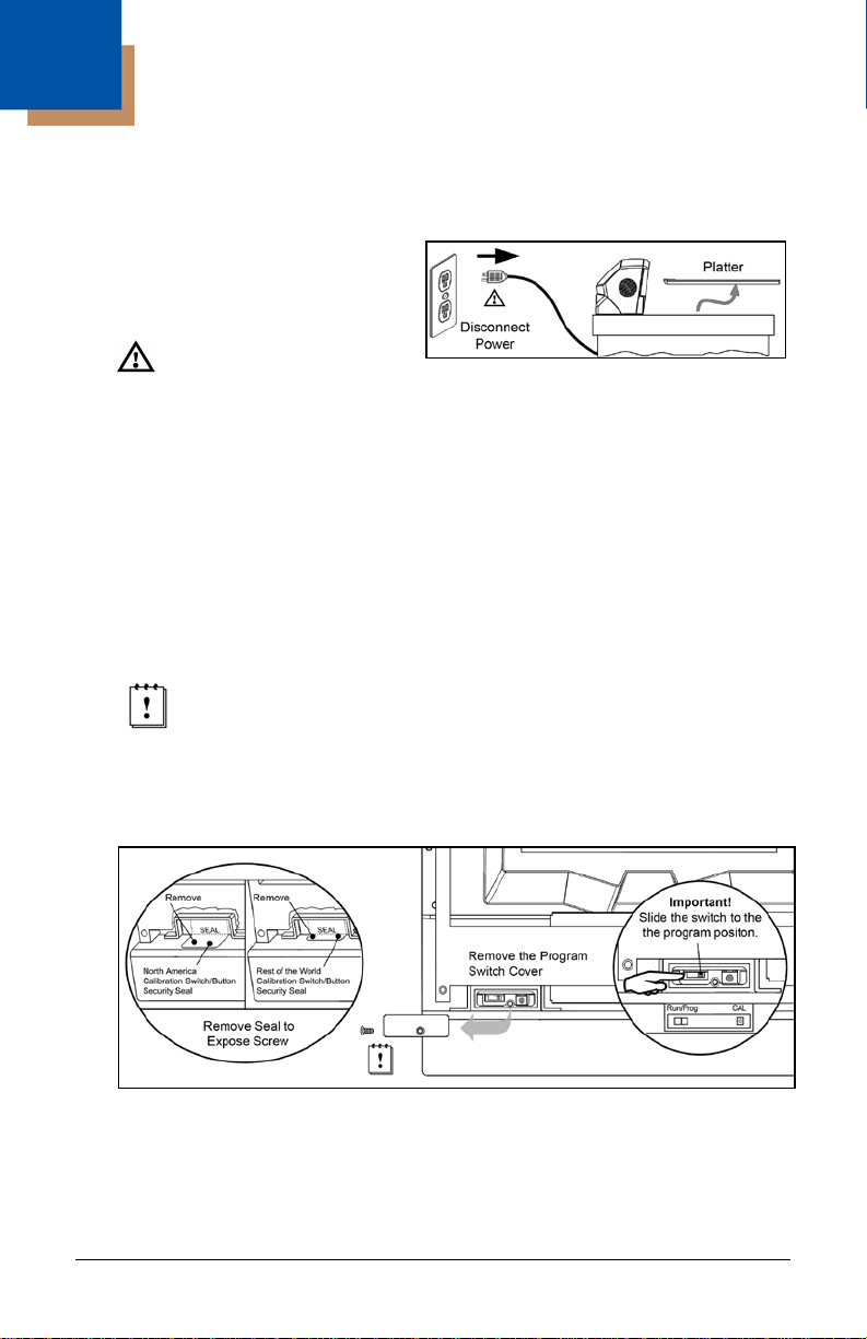
1. Power down the scanner/scale.
Then, temporarily remove the
scale platter and place it in a safe
location.
See caution on page 4.
2. Cut and remove the security seal over the program/calibration switch cover.
See Figure 2 below for seal location on the StratosE and the StratosH
models. See Figure 3 on page 4 for the seal location on the StratosS.
Note: Once the security seal is cut the unit cannot be placed in service until
it is calibrated, sealed and certified by local Weights and Measures
authority.
3. Remove the M3 screw securing the switch cover in place. Store the cover
and screw in a safe location. They will be needed again after the scale is
configured and calibrated.
Always follow all Electro-Static Discharge (ESD) procedures when
exposing the internal scanner/scale components.
4. Enter the scale program mode by sliding the switch to the program
position. See Figure 2 below for the switch locatio n on the St rat osE and
StratosH. See Figure 3 on page 4 for the switch location on the StratosS.
Figure 1.
Figure 2. StratosE and StratosH Calibration Seal and Switch Location
Page 10

4
Figure 3. StratosS Calibration Seal and Switch Location
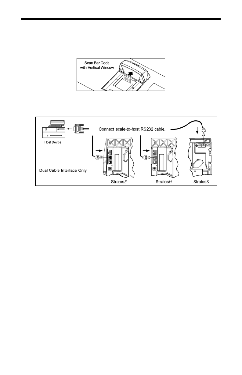
5. Disconnect the scale-to-host RS232 cable from the unit (dual cable
interface only.)
Figure 4. Disconnect scale-to-host RS232 Cable
6. Reinstall the platter and connect AC power to the scanner.
Note: Check the AC input requirements of the power supply to make sure
the voltage matches the AC outlet. The outlet should be located
near the equipment and be easily accessible.
Honeywell recommends using a switched AC outlet. The switch
should be located on the operator’s side of the checkout counter in
close proximity to the scanner/scale to facilitate calibration and
service of the unit.
Caution: To maintain compliance with applicable standards, all circuits connected to
To maintain compliance with standard CSA C22.2 No. 60950-1/UL 60950-1
the imager must meet the requirements for SELV (Safety Extra Low Voltage)
according to EN/IEC 60950-1.
and norm EN/IEC 60950-1, the power source should meet applicable
performance requirements for a limited power source.
Page 11
5
7. If the system is equipped with a remote scale display, it will read H - - -.
8. Use the vertical window to scan the desired scale configuration bar
codes, located on pages 7 - 21.
Figure 5.
9. Reconnect the scale-to-host RS232 cable to the scanner (dual cable
interface only.)
Figure 6.
10. The scale must now be calibrated, tested and certified by local Weights
and Measures authorities before it can be placed in service.
For further details on calibration procedures for Weight s and M easur es
certification, refer to the Scale Operation: Calibration section of the Stratos
Installation and User’s Guide.
Important Notes
The certification of the weighing mechanism of the scale version of this
scanner is subject to federal, state and local Weights and Measures
statutes and regulations and can only be performed by authorized
government agencies and/or their duly registered agents. Each time the
scale or weighing mechanism is calibrated, it should be properly sealed
with a paper seal or a wire seal prior to being placed into service in
commerce.
It is the responsibility of the owner of the scale to confirm compliance
with the relevant Weights and Measures statutes and regulations
applicable in your area by checking with the appropriate government
agency before placing a newly calibrated unit into service or removing
any official seals.
Type of seal to be used will depend on the guidelines specified by the
local Weights and Measures authorities.
Page 12

6
Page 13

7
Scale = Pounds
³ 9 9 6 0 0 1
Set the scale measuring range from
Scale = Kilograms
³ 9 9 6 0 0 2
Set the scale measuring range from
Scale/Load Cell Configuration
Bar Codes
Single or Dual Cable Scale Configuration Bar Codes
Unit Configuration (Pounds or Kilograms)
The following bar codes can be used to configure a Single or Dual Cable
MS2xx0.
The MS2xx0 must be in scale program mode to use these bar codes.
0.00 to 30.00 pounds.
0.000 to 15.000 kilograms.
Page 14
8
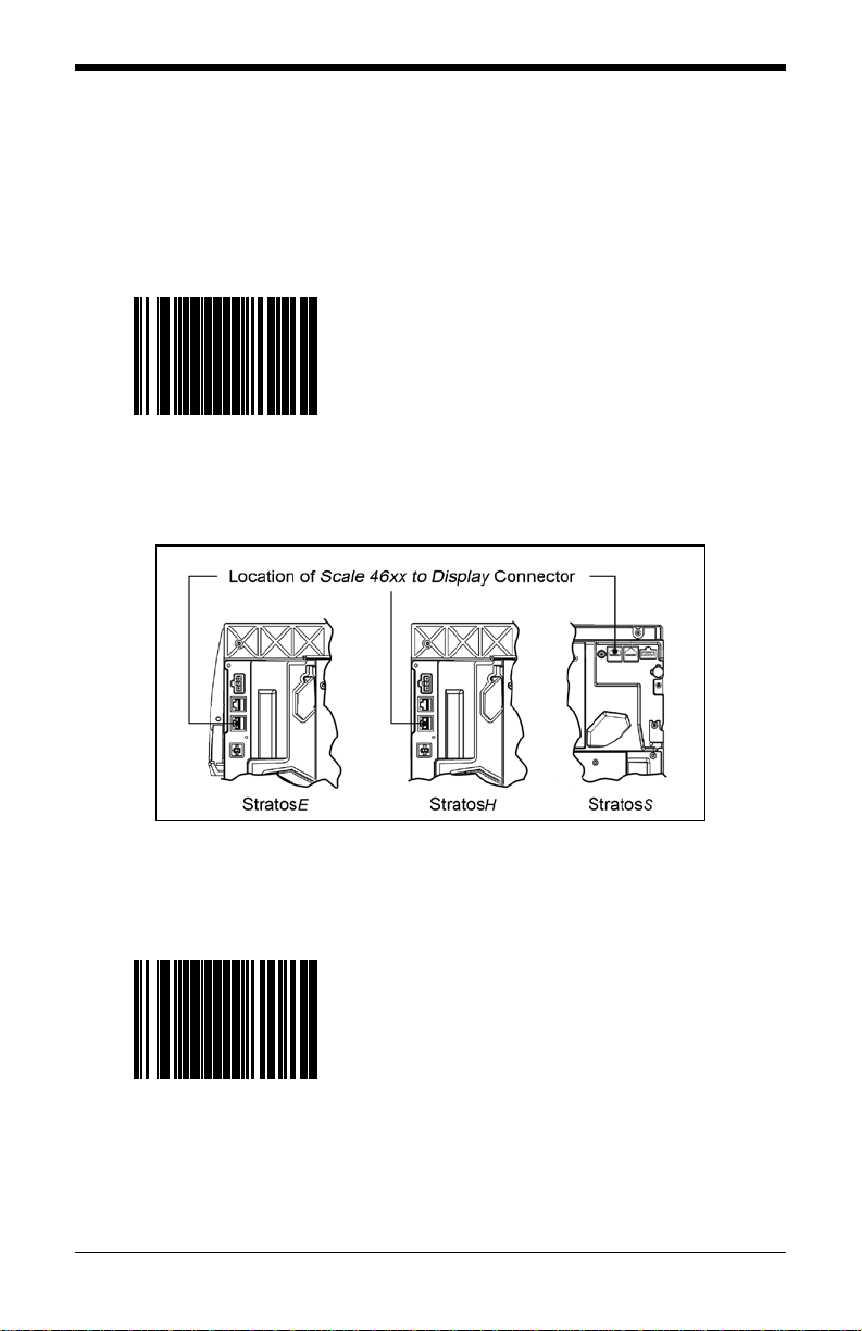
Scale Has Display
³ 9 9 6 0 0 3
Set the scale to use a remote display to
Scale Has No Display
³ 9 9 6 0 0 4
Set the scale to not use a remote display.
Pole Display Configuration
The following bar codes can be used to configure a Single or Dual Cable
MS2xx0.
The MS2xx0 must be in scale program mode to use these bar codes.
show all scale activity.
A remote display must be plu gged into the
Scale 46xx to Display connector on the
MS2xx0 (see Figure 7) for this feature to
function properly.
Figure 7. Location of Scale 46xx to Display Connector
All weights are expected on a POS terminal
display.
A remote display cannot be plugged into the
Scale 46xx to Display connector on the
scanner/scale (see Figure 7) or this feature
will not function properly.
Page 15

9
³ 9 9 6 0 0 5
Scale Settling Filter Configuration
The following bar code can be used to configure a Single or Dual Cable
MS2xx0.
The MS2xx0 must be in scale program mode to use this bar code.
The scale’s filter setting allows the unit to withstand a certain amount of vibration
from the checkout counter. A stronger filter allows for more vibration to be
absorbed but the weight may take a little longer to settle. Scales are normally
shipped with a loose filter.
* Scale = Loose Filter
Loose filter setting for low vibration
environments.
* Factory Default Setting
Page 16

10
Scale = Medium Filter
³ 9 9 6 0 0 6
Medium filter setting for moderate vibration
Scale = Strong Filter
³ 9 9 6 0 0 7
Strong filter setting for high vibration
Scale Settling Filter Configuration
The following bar codes can be used to configure a Single or Dual Cable
MS2xx0.
The MS2xx0 must be in scale program mode to use these bar codes.
environments.
environments.
Page 17

11
Scale = Scroll Settling Weight
³ 9 9 6 0 1 0
Scroll the weight on the display showing the
³ 9 9 6 0 1 1
Scroll Weight Configuration
The following bar codes can be used to configure a Single or Dual Cable
MS2xx0.
The MS2xx0 must be in scale program mode to use these bar codes.
These bar codes only affect the pole display.
weight as it changes.
Scale = Blank Non-Steady
Blank the display weight as it changes.
Display stable weights only.
Page 18

12
³ 9 9 6 0 0 8
Scale = Price Comput ing
³ 9 9 6 0 0 9
Scale is the price computing type.
Dual Cable Scale Configuration Bar Codes
Price Computing Configuration
The following bar codes are only used when the scale is in Dual Cable mode.
The MS2xx0 must be in scale program mode to use these bar codes.
Scale is not the price computing type.
* Scale = No Price Computing
* Factory Default Setting
Page 19

13
³ 9 9 6 0 1 3
³ 9 9 6 0 1 4
Set the scale RS232 protocol to
Scale Protocols
The following bar codes will change scale parameters intended for a Dual Cable
environment. To place the scanner in Dual Cable mode, please refer to
page 23.
The MS2xx0 must be in scale program mode to use these bar codes.
Scale = EPOS Protocol
Set the scale RS232 protocol to
Serial EPOS.
Communication Port Settings:
• 2400 Baud
• 7 Data Bits
• 1 Stop Bit
• Even Parity
Scale = EPOS2 Protocol
Modified Serial EPOS.
This Protocol does not require the POS
terminal to send the weight back to the scale
for validation.
Communication Port Settings:
• 2400 Baud
• 7 Data Bits
• 1 Stop Bit
• Even Parity
Page 20

14
³ 9 9 6 0 1 5
Scale = NCI Protocol
³ 9 9 6 0 1 6
Reserved for Future NCI Protocol Variation
Scale Protocols
The following bar codes will change scale parameters intended for a Dual Cable
environment. To place the scanner in Dual Cable mode, please refer to
page 23.
The MS2xx0 must be in scale program mode to use these bar codes.
Scale = NCI-ECR Protocol
Set the scale RS232 protocol to NCI-ECR.
Communication Port Settings:
• 9600 Baud
• 8 Data Bits
• 1 Stop Bit
• No Parity
Page 21

15
³ 9 9 6 0 4 1
Scale Protocols
The following bar code will change scale parameters intended for a Dual Cable
environment. To place the scanner in Dual Cable mode, please refer to
page 23.
The MS2xx0 must be in scale program mode to use this bar code.
Scale = EMEA
Special Configuration
Set the scale to Avery EPOS protocol,
kilograms, with a remote display, loose filter,
no price computing, and scroll weight.
Communication Port Settings:
• 2400 Baud
• 7 Data Bits
• 1 Stop Bit
• Even Parity
Page 22

16
Scale = 2400 Baud Rate
³ 9 9 6 0 1 7
Set the scale baud rate for dual cable
Scale = 9600 Baud Rate
³ 9 9 6 0 1 8
Set the scale baud rate for dual cable
COM Port Settings (Baud Rate)
The following bar codes will change scale parameters intended for a Dual Cable
environment.
If a Scale Protocol bar code from page 13 or 15 is used, the bar codes below
must be scanned after the Scale Protocol bar code in order to be effective.
The MS2xx0 must be in scale program mode to use these bar codes.
applications to 2400 baud.
applications to 9600 baud.
Page 23

17
Scale = 19200 Baud Rate
³ 9 9 6 0 1 9
Set the scale baud rate for dual cable
Scale = 38400 Baud Rate
³ 9 9 6 0 2 0
Set the scale baud rate for dual cable
COM Port Settings (Baud Rate)
The following bar codes will change scale parameters intended for a Dual Cable
environment.
If a Scale Protocol bar code from page 13 or 15 is used, the bar codes below
must be scanned after the Scale Protocol bar code in order to be effective.
The MS2xx0 must be in scale program mode to use these bar codes.
applications to 19200 baud.
applications to 38400 baud.
Page 24

18
Scale = 7 Data Bits,
³ 9 9 6 0 2 1
Set the scale communication parameters to
Scale = 7 Data Bits,
³ 9 9 6 0 2 2
Set the scale communication parameters to
COM Port Settings (Data Bits & Parity)
The following bar codes will change scale paramete r s inte nd ed for a Dual Cable
environment.
If a Scale Protocol bar code from page 13 or 15 is used, the bar codes below
must be scanned after the Scale Protocol bar code in order to be effective.
The MS2xx0 must be in scale program mode to use these bar codes.
Odd Parity
7 data bits, odd parity.
Even Parity
7 data bits, even parity.
Page 25

19
Scale = 8 Data Bits, No Parity
³ 9 9 6 0 2 3
Set the scale communication parameters to
Scale = Odd Parity
³ 9 9 6 0 2 4
Set the scale communication to odd parity.
COM Port Settings (Data Bits & Parity)
The following bar codes will change scale parameters intended for a Dual Cable
environment.
If a Scale Protocol bar code from page 13 or 15 is used, the bar codes below
must be scanned after the Scale Protocol bar code in order to be effective.
The MS2xx0 must be in scale program mode to use these bar codes.
8 data bit, no parity.
Page 26

20
Scale = Even Parity
³ 9 9 6 0 2 5
Set the scale communication to even parity.
Scale = No Parity
³ 9 9 6 0 2 6
Set the scale communication to no parity.
COM Port Settings (Data Bits & Parity)
The following bar codes will change scale parameters intended for a Dual Cable
environment.
If a Scale Protocol bar code from page 13 or 15 is used, the bar codes below
must be scanned after the Scale Protocol bar code in order to be effective.
The MS2xx0 must be in scale program mode to use these bar codes.
Page 27

21
Scale = Single Cable Interface
³ 9 9 6 0 1 2
Set the scale to communicate via the
Single Cable Scale Configuration Bar Codes
Set Scale for Single Cable Communication
The MS2xx0 must be in scale program mode to use this bar code.
If your application requires single cable communication, scan the following bar
code to set the scale configuration to the single cable defaults as required by the
scanner.
single-cable interface.
Page 28

22
Page 29

23
Scanner = Dual Cable Mode
³ 9 9 9 9 5 3
Places the scanner in Dual Cable mode.
Communication Port Settings:
³ 9 9 9 9 1 1
Use this bar code when the scanner is to be
Scanner Configuration Bar Codes
Dual Cable Scanner Configuration Bar Codes
Dual Cable Scanner Mode
The following bar codes can be used to place, as well as configure, the scanner
in Dual Cable mode.
The MS2xx0 does not need to be in scale program mode to use the following
bar codes.
In a dual cable environment, the scanner
and scale work independently. In this mode
the host must have a dedicated RS232 port
to receive the scale data and the bar code
• 9600 Baud, 8 Data Bits, 1 Stop Bit, No Parity
There are two methods of configuring the scanner to a stand-alone protocol:
• Scan the Dual Cable Mode bar code on this page (if a scale is used)
or
• If no scale is required, scan one of the single cable protocols on
pages 26 - 34 and then scan the No Scale bar code on page 46.
data is sent via its own cable to a separate
communication port.
Dual Cable Scanner OPOS Mode
Scanner Only
Dual Cable OPOS Defaults
setup using the OPOS drivers in the dual
cable mode.
Communication Port Settings:
• 9600 Baud
• 8 Data Bits
• 1 Stop Bit
• No Parity
Page 30

24
REWE
³ 9 9 7 0 1 0
Dual Cable RS232 - REWE
³ 9 9 7 0 1 3
Various Dual Cable Scanner Mode
The following bar codes can be used to configure a Dual Cable MS2xx0.
The following codes do not require that the MS2xx0 to be in scale program
mode.
Communication Port Settings:
• 9600 Baud
• 7 Data Bits
• 2 Stop Bit
• Space Parity
TESCO UK
Dual Cable RS232 – TESCO UK
Communication Port Settings:
• 9600 Baud
• 8 Data Bits
• 1 Stop Bit
• Odd Parity
Page 31

25
IBM 3rd Generation
³ 9 9 9 9 5 2
When scanned the Stratos will operate
³ 9 9 9 9 7 0
IBM 3rd Generation 46xx and IBM OEM Full Speed USB
The following bar codes can be used to configure a Dual Cable MS2xx0.
The following codes do not require that the M S2xx0 to be in scale program
mode.
Communication
IBM OEM Full Speed USB
Communication Defaults
as a table top scanner only.
Terminal configuration, IBM 4690.OS
terminal device group configuration
screen select:
#1 scanner or
#3 scanner.
When scanned the Stratos will operate
as a table top scanner only.
Page 32

26
MSS Global, English
³ 9 9 9 9 5 1
Scanner/Scale, Single Cable RS232
³ 9 9 9 9 5 0
Scanner/Scale, Single Cable RS232 MSS
Single Cable Protocols for POS Compatibility
MSS Global
The following bar codes can be used to configure a Single Cable MS2xx0.
The following codes do not require that the MS2xx0 to be in scale program
mode.
MSS Global Retail, English Units
Communication Port Settings:
• 9600 Baud
• 7 Data Bits
• 1 Stop Bit
• Odd Parity
MSS Global, Metric
Global Retail, Metric Units
Communication Port Settings:
• 9600 Baud
• 7 Data Bits
• 1 Stop Bit
• Odd Parity
Page 33

27
ISS45, English
³ 9 9 9 9 4 9
Scanner/Scale, Single Cable RS232
³ 9 9 9 9 4 8
Scanner/Scale, Single Cable RS232
ISS45
The following bar codes can be used to configure a Single Cable MS2xx0.
The following codes do not require that the MS2xx0 to be in scale program
mode.
ISS45, English Units
Communication Port Settings:
• 9600 Baud
• 7 Data Bits
• 1 Stop Bit
• Even Parity
ISS45, Metric
ISS45, Metric Units
Communication Port Settings:
• 9600 Baud
• 7 Data Bits
• 1 Stop Bit
• Even Parity
Page 34

28
OPOS, English
³ 9 9 9 9 5 8
Scanner/Scale Single Cable RS232 OPOS,
³ 9 9 9 9 5 7
Scanner/Scale Single Cable RS232 OPOS,
OPOS
The following bar codes can be used to configure a Single Cable MS2xx0.
The following codes do not require that the MS2xx0 to be in scale program
mode.
English Scale Defaults
Communication Port Settings:
• 9600 Baud
• 8 Data Bits
• 1 Stop Bit
• No Parity
OPOS, Metric
Metric Scale Defaults
Communication Port Settings:
• 9600 Baud
• 8 Data Bits
• 1 Stop Bit
• No Parity
Page 35

29
Retalix/NCR English
³ 9 9 9 9 5 6
Scanner/Scale Single Cable RS232
³ 9 9 9 9 5 5
Scanner/Scale Single Cable RS232
Retalix/NCR
The following bar codes can be used to configur e a Single Cable MS2xx0.
The following codes do not require that the MS2xx0 to be in scale program
mode.
Retalix/NCR Communication, English
Communication Port Settings:
• 9600 Baud
• 8 Data Bits
• 1 Stop Bit
• No Parity
Retalix/NCR Metric
Retalix/NCR Comm, Metric
Communication Port Settings:
• 9600 Baud
• 8 Data Bits
• 1 Stop Bit
• No Parity
Page 36

30
IT Retail, English
³ 9 9 7 0 0 8
Scanner/Scale Single Cable RS232
³ 9 9 7 0 0 9
Scanner/Scale Single Cable RS232
IT Retail
The following bar codes can be used to configure a Single Cable MS2xx0.
The following codes do not require that the MS2xx0 to be in scale program
mode.
IT Retail, English
Communication Port Settings:
• 9600 Baud
• 7 Data Bits
• 1 Stop Bit
• Odd Parity
IT Retail, Metric
IT Retail, Metric
Communication Port Settings:
• 9600 Baud
• 7 Data Bits
• 1 Stop Bit
• Odd Parity
Page 37

31
IBM Self Checkout System,
³ 9 9 7 0 2 0
Scanner/Scale Single Cable RS232 -
³ 9 9 7 0 2 1
Scanner/Scale Single Cable RS232 -
IBM Self Checkout System
The following bar codes can be used to configure a Single Cable MS2xx0.
The following codes do not require that the MS2xx0 to be in scale program
mode.
English
IBM Self Checkout System, English
Communication Port Settings:
• 19200 Baud
• 7 Data Bits
• 1 Stop Bit
• Odd Parity
IBM Self Checkout System,
Metric
IBM Self Checkout System, Metric
Communication Port Settings:
• 19200 Baud
• 7 Data Bits
• 1 Stop Bit
• Odd Parity
Page 38

32
Morrison’s Tec Metric
³ 9 9 7 0 2 3
Scanner/Scale Single Cable RS232 –
³ 9 9 7 0 1 9
Various RS232 Single Cable Codes
The following bar codes can be used to configure a Single Cable MS2xx0.
The following codes do not require that the MS2xx0 to be in scale program
mode.
Morrison’s with Tec Display, Metric
Communication Port Settings:
• 9600 Baud
• 7 Data Bits
• 1 Stop Bit
• Odd Parity
Reliance India Metric
Scanner/Scale Single Cable RS232 -
Reliance India, Metric
Communication Port Settings:
• 9600 Baud
• 8 Data Bits
• 1 Stop Bit
• No Parity
Page 39

33
IBM 3rd Generation 46xx,
³ 9 9 9 9 6 0
Scanner/Scale Single Cable
IBM 3rd Generation 46xx,
³ 9 9 9 9 5 9
Scanner/Scale Single Cable
IBM 3rd Generation 46xx
The following bar codes can be used to configure a Single Cable MS2xx0.
The following codes do not require that the MS2xx0 to be in scale program
mode.
†
English
IBM 46xx†, RS485,
English (lbs.)
† Terminal Configuration, IBM 4690.OS Terminal Device Group
Configuration screen select:
#2 Scanner with integrated scale
or
#4 4696 scanner/scale
Metric†
IBM 46xx†, RS485
Metric (kg)
Page 40

34
IBM OE M
³ 9 9 9 9 6 2
Table Top Scanner/Scale Single Cable,
IBM OE M
³ 9 9 9 9 6 1
Table Top Scanner/Scale Single Cable,
IBM OEM Full Speed USB
The following bar codes can be used to configure a Single Cable MS2xx0.
The following codes do not re quire that the M S 2x x 0 to be in scale program
mode.
Full Speed USB, English
Full Speed USB, Metric
IBM OEM Full Speed USB,
4-Digit Weight Mode, English (lbs.)
IBM OEM Full Speed USB,
5-Digit Weight Mode, Metric (kg)
Page 41

35
³ 3 1 6 4 3 0
Scanner 4A Flatbed
³ 3 1 6 4 1 0
Full Speed USB interface to 4A00h
Additional POS Data Formatting
Full Speed USB Table Top/Handheld
The following codes do not require that t he M S2x x 0 to be in scale program
mode.
Scanner 4B Handheld
Full Speed USB interface to 4B00h
handheld usage.
table top usage.
Page 42

36
Scanner/Scale 4A/6E
³ 3 1 6 4 4 0
Full Speed USB interface to the
Full Speed USB Table Top/Handheld
The following codes do not re quire that the MS2xx0 to be in scale program
mode.
Table Top
4A00h/6E00h table top scanner/scale
usage.
This option is only compatible with Stratos
models that have a scale.
Page 43

37
Enable Special
³ 1 4 1 7 1 4
Answer simple special functions with ACK.
* Disable Special
³ 1 4 1 7 0 4
Special Function ACK
The following codes do not require that the MS2xx0 to be in scale program
mode.
Function ACK Answer
Function ACK
* Factory Default Setting
Page 44

38
Use Protocol Prefix/Suffix
³ 1 4 1 7 1 5
Add protocol prefixes and suffixes to the
* Program the
³ 1 4 1 7 0 5
Prefix/Suffix
The following codes do not require that the MS2xx0 to be in scale program
mode.
bar code.
Prefix/Suffix Separate
* Factory Default Setting
Page 45

39
No 3x-30 Answer
³ 1 4 1 7 1 0
This bar code will inhibit all ‘simple
*3x-30 Answer
³ 1 4 1 7 0 0
The scanner will answer all NCR and OPOS
3x-30 Acknowledge Responses
The following codes do not require that the MS2xx0 to be in scale program
mode.
acknowledge’ (3x-30) answers to POS or
OPOS commands.
commands that require a 3x-30
acknowledgement.
* Factory Default Setting
Page 46

40
Spec Func Ans 3x30
³ 1 4 1 9 1 4
Answer Special Function commands in the
*Spec Func Ans Ack
³ 1 4 1 9 0 4
Answer Special Function commands in the
Special Function Command Responses
The following codes do not require that the MS2xx0 to be in scale program
mode.
3x-30 format as opposed to the Ack / Nak
which is the norm.
Ack / Nak format.
* Factory Default Setting
Page 47

41
Spec Func 30-30 Status
³ 1 4 2 2 1 5
Returns Special Function commands in the
*No Spec Func 30-30 Status
³ 1 4 2 2 0 5
Disables redirection of Special Function
Special Function Command Responses
The following codes do not require that the MS2xx0 to be in scale program
mode.
30-30 status as opposed to the 33-30 status.
Note: Requires ‘Spec Func Ans 3x-30’ on
page 40 to be set.
3x-30 status to 30-30 status.
* Factory Default Setting
Page 48

42
No Command Reject Answer
³ 1 4 2 1 1 7
This bar code will ignore sending a
*Send Command Reject
³ 1 4 2 1 0 7
This bar code will send command reject
Special Function Command Responses
The following codes do not require that the MS2xx0 to be in scale program
mode.
command reject answer to the POS mode.
Answer
answer to the POS if the command is
rejected by the scanner.
* Factory Default Setting
Page 49

43
No Spec Func Answer
³ 1 4 2 1 1 6
This bar code will ignore sending a special
*Spec Func Answer
³ 1 4 2 1 0 6
This bar code will send a special function
Special Function Command Responses
The following codes do not re quire that t he M S2x x 0 to be in scale program
mode.
function response answer in POS mode.
response answer to the POS.
* Factory Default Setting
Page 50

44
Skip BCC in messages
³ 1 4 1 4 1 0
This bar code will tell the scanner to NOT
*Add BCC in messages
³ 1 4 1 4 0 0
The scanner will expect and answer all
BCC in POS communications
The following codes do not require that the MS2xx0 to be in scale program
mode.
expect or transmit the Block Check
Character in all message transmissions.
messages with the Block Check Character
included.
* Factory Default Setting
Page 51

45
Enable
³ 1 2 4 8 1 3
Required for applications where the host
³ 1 2 4 8 0 3
3 Scale Status Bytes
The following codes do not require that the MS2xx0 to be in scale program
mode.
3 Scale Status Bytes
Disable
3 Scale Status Bytes
system display is the primary scale display
and there is no remote pole display
connected directly to the scanner/scale unit.
Page 52

46
5-Digit Weight
³ 1 4 1 0 1 0
Sets the English Mode weight to 5-digits, as
³ 1 4 1 4 0 7
Scan the No Scale bar code:
Scale Options
The following codes do not require that the MS2xx0 to be in scale program
mode.
in xx.yyy pounds.
In order to work properly, this bar code must
be scanned AFTER scanning one of the
English configuration bar codes found on
pages 26 - 34.
No Scale
1. If no scale is installed and one of the
single cable protocol bar codes found
on pages 26 - 34 has already been
scanned.
2. If the scale is in a dual cable
environment and one of the single cable
protocol bar codes found on
pages 26 - 34 has already been
scanned.
Page 53

47
No Remote Display
³ 1 4 0 9 0 2
When no remote display is installed, scan
³ 1 4 0 9 1 2
Remote Display
The following codes do not require that the MS2xx0 to be in scale program
mode.
the No Remote Display bar code AFTER
scanning one of the configuration bar codes
found on pages 26 - 34 to remove the
scale’s display from the scanner memory.
Remote Display
Add remote display to the scanner’s
memory.
Page 54

48
Activate StratosSTATS
³ 9 9 7 0 1 7
This bar code sets:
*StratosSTATS Off
³ 9 9 7 0 1 8
Remove StratosSTATS data formatting from
StratosSTATS
The following codes do not require that the MS2xx0 to be in scale program
mode.
• StratosSTATS bar code data
formatting active.
• Bar code Attempt Interval to
0.5 seconds.
• Time to find supplements (code 128)
to 0.3 seconds.
Use StratosSTATS monitor to test this
output format. When used with a POS, it
must have the capability to parse and
recognize the additional data.
the bar code output transmission.
* Factory Default Setting
Page 55

49
³ 1 3 8 5 1 1
*No Dual Stats Xmit
³ 1 3 8 5 0 1
StratosSTATS
The following codes do not require that the MS2xx0 to be in scale program
mode.
Do not scan these bar codes unless instruct ed by a customer service
representative.
Dual Stats Xmit
Allows non-RS232 interfaces transmit
normally without StratosSTATS and
concurrently RS232 interfac es transmit with
StratosSTATS.
Recommended RS232 Settings:
• 38400 Baud
• 8 Data Bits
• 1 Stop Bit
• No Parity
• No Inter-character Delay
* Factory Default Setting
Page 56

50
³ 1 3 8 5 1 2
*No Dual Xmit Carriage Return
³ 1 3 8 5 0 2
Resets StratsSTATS RS232 dual
StratosSTATS
The following codes do not require that the MS2xx0 to be in scale program
mode.
Do not scan these bar codes unless instruc ted by a customer service
representative.
Dual Xmit Carriage Return
This bar code enables a secondary carriage
return suffix to be used only for the dual
StratosSTATS RS232 transmission.
transmission suffix.
* Factory Default Setting
Page 57

51
³ 1 4 1 9 1 7
*Disable
³ 1 4 1 9 0 7
When no beep on weight is desired.
Additional POS Related Functions
Scanner Beep on Weight Sent
The following codes do not require that the MS2xx0 to be in scale program
mode.
Beep on Weight
Request scanner beep when a successful
weight is sent. This code should only be
used for ‘weight on demand’ applications. If
used with periodic weight request
applications, the beeper will be continuously
active (ON).
Beep on Weight
* Factory Default Setting
Page 58

52
Restrict In-Store Codes
³ 1 2 5 8 1 0
This bar code places tighter restrictions on
*No Restrict In-Store Codes
³ 1 2 5 8 0 0
Disable restrictions on in-store codes.
Restrict In-Store Codes
The following codes do not require that the MS2xx0 to be in scale program
mode.
in-store codes. These codes are:
EAN13 Sys2
UPCA Sys2 and Sys4
* Factory Default Setting
Page 59

53
Scale Shadow Mode
³ 1 4 2 2 1 7
This bar code sets the scale to the highest
*No Scale Shadow Mode
³ 1 4 2 2 0 7
Disables the Scale Shadow Mode.
Scale Shadow Mode
The following codes do not require that the MS2xx0 to be in sca le progr a m
mode.
priority to allow for frequent scale - POS
commands.
This bar code is only to be used in single
cable scale mode.
* Factory Default Setting
Page 60

54
Razz on Not-On-File
³ 1 4 2 1 1 5
This bar code changes the audible to a razz
*Beep on Not-On-File
³ 1 4 2 1 0 5
This bar code restores the beep as the Not-
Scanner Razz on Not-On-File
The following codes do not require that the MS2xx0 to be in scale program
mode.
signal when a Not-On-File command is
received.
On-File audible.
* Factory Default Setting
Page 61

55
*Horizontal High DOF
³ 2 1 8 7 0 2
This bar code sets the DOF for all horizontal
Horizontal Medium DOF
³ 2 1 8 7 1 2
This bar code sets the DOF for all horizontal
Additional Scanner Configuration Bar Codes
Horizontal Depth of Field
The following codes do not require that the MS2xx0 to be in scale program
mode.
Do not scan these bar codes unless instruc ted by a customer service
representative.
laser channels to High DOF, which allows
the farthest scanning.
* Factory Default Setting
laser channels to Medium DOF.
Page 62

56
³ 2 1 8 7 2 2
Horizontal Ultra Close DOF
³ 2 1 8 7 3 2
This bar code sets the DOF for all horizontal
Horizontal Depth of Field
The following codes do not require that the MS2xx0 to be in scale program
mode.
Do not scan these bar codes unless instruc ted by a customer service
representative.
Horizontal Close DOF
This bar code sets the DOF for all horizontal
laser channels to Close DOF.
laser channels to Ultra Close DOF.
Page 63

57
*Vertical High DOF
³ 2 1 8 7 0 0
Vertical Medium DOF
³ 2 1 8 7 1 0
This bar code sets the DOF for vertical laser
Vertical Depth of Field
The following codes do not require t hat the MS2xx0 to be in scale program
mode.
Do not scan these bar codes unless instruc ted by a customer service
representative.
This bar code sets the DOF for the vertical
laser channels to High DOF, which allows
the farthest scanning.
* Factory Default Setting
channels to Medium DOF.
Page 64

58
³ 2 1 8 7 2 0
Vertical Ultra Close DOF
³ 2 1 8 7 3 0
This bar code sets the DOF for vertical laser
Vertical Depth of Field
The following codes do not require that the MS2xx0 to be in scale program
mode.
Do not scan these bar code s unle ss inst ruc ted by a customer service
representative.
Vertical Close DOF
This bar code sets the DOF for the vertical
laser channels to Close DOF.
channels to Ultra Close DOF.
Page 65

59
³ 9 9 7 0 1 1
Auxiliary Port
StratosSCHOOL™
The following codes do not require that the MS2xx0 to be in scale program
mode.
Auxiliary History Report
The Auxiliary port may be used to download
or clear data to StratosSCHOOL™.
The two commands that can be used are
Upload Scanner Data and Clear Scanner
Data within the Serial Program Interface box
on the StratosSCHOOL™ screen.
Auxiliary Program Cable
(PN 57-57008x-N-3) is required
for this feature.
Page 66

60
Enable Stratos Auxiliary Port
³ 4 3 7 3 2 0
³ 1 3 7 2 1 3
Quick Start for a Secondary Honeywell Scanner
The following codes do not require that the MS2xx0 to be in scale program
mode.
Step 1
Use the Stratos to scan the following bar codes. These bar codes will
configure the Stratos’ auxiliary port to accept a Honeywell scanner as the
secondary scanner.
Aux 8 Data Bits
Note: The auxiliary input port’s data format must mat ch the main ou tput for mat
of the secondary scanner
Page 67

61
Enter Configuration Mode
³ 9 9 9 9 9 9
Enable Auxiliary Output
³ 1 2 4 8 1 7
³ 4 3 7 5 2 0
Disable Secondary
³ 3 1 8 5 0 5
Enable Communication
³ 1 1 8 4 1 2
³ 1 1 6 6 0 3
Step 2
Configure the secondary scanner to match the auxiliary port’s data format.
Use the Secondary Scanner to scan the following bar codes in the order
shown.
Set Stratos Format
Scanner Beeper
Time Out
Disable CR Suffix
Page 68

62
Disable LF Suffix
³ 1 1 6 6 0 2
Exit Configuration Mode
³ 9 9 9 9 9 9
Quick Start for a Secondary Honeywell Scanner
Configuration sequence continued from previous page.
Page 69

EAS Bar Codes
EAS Device Types
The following codes do not require that the MS2xx0 to be in scale program
mode.
*No EAS Device
³337200
No EAS device is connected.
* Factory Default Setting
EAS Device Type 1
³337210
Sensormatic ScanMax Pro
63
Page 70

64
EAS Device Type 2
³ 3 3 7 2 2 0
EAS Device Type 3
³ 3 3 7 2 3 0
EAS Device Types
The following codes do not require that the MS2xx0 to be in scale program
mode.
Page 71

65
EAS Device Type 4
³ 3 3 7 2 4 0
EAS Device Types
The following codes do not require that the MS2xx0 to be in scale program
mode.
Page 72

66
*EAS = 0 seconds
³ 8 4 6 0 0 0
EAS = 1 second
³ 8 4 6 0 0 1 0 0
EAS Timeout
The following codes do not require that the MS2xx0 to be in scale program
mode.
* Factory Default Setting
Page 73

67
EAS = 2 seconds
³ 8 4 6 0 0 2 0 0
EAS = 3 seconds
³ 8 4 6 0 0 3 0 0
EAS Timeout
The following codes do not require that the MS2xx0 to be in scale program
mode.
Page 74

68
EAS = 4 seconds
³ 8 4 6 0 0 4 0 0
EAS = 5 seconds
³ 8 4 6 0 0 5 0 0
EAS Timeout
The following codes do not require that the MS2xx0 to be in scale program
mode.
Page 75

69
EAS = 7 seconds
³ 8 4 6 0 0 7 0 0
EAS = 10 seconds
³ 8 4 6 0 1 0 0 0
EAS Timeout
The following codes do not require that the MS2xx0 to be in scale program
mode.
Page 76

70
EAS = 15 seconds
³ 8 4 6 0 1 5 0 0
EAS = 20 seconds
³ 8 4 6 0 2 0 0 0
EAS Timeout
The following codes do not require that the MS2xx0 to be in scale program
mode.
Page 77

71
*EAS Digital Aux Port
³ 1 4 6 1 0 0
The EAS signals use the RTS and CTS line
EAS Digital Host Port
³ 1 4 6 1 1 0
The EAS signals use the RTS and CTS lines
EAS Connection
The following codes do not require that the MS2xx0 to be in scale program
mode.
of the Auxiliary RS232 In connector.
* Factory Default Setting
of the scanner RS232 to Host connector.
Page 78

72
EAS RS232 on Aux Port
³ 1 4 6 1 1 1
This bar code allows the EAS RS232 signal
*No EAS RS232 on Aux Port
³ 1 4 6 1 0 1
There is no EAS RS232 signal (Tx Out and
EAS Connection
The following codes do not require that the MS2xx0 to be in scale program
mode.
to use the Tx Out and Rx In lines of the
scanner to Aux RS232 In connector.
Rx In) used on the scanner Aux RS232 In
connector.
* Factory Default Setting
Page 79

73
EAS RS232 on Host Port
³ 1 4 6 1 1 2
This bar code allows the EAS RS232 signal
*No EAS RS232 on Host Port
³ 1 4 6 1 0 2
There is no EAS RS232 signal (Tx Out and
EAS Connection
The following codes do not require that the MS2xx0 to be in scale program
mode.
to use the Tx Out and Rx In lines of the
scanner to Host RS232 In connector.
Rx In) used on the scanner to Host RS232
In connector.
* Factory Default Setting
Page 80

74
EAS Continuous Mode
³ 1 4 6 1 1 5
When in continuous mode and the scanner
*EAS Interlock Mode
³ 1 4 6 1 0 5
This bar code establishes EAS is used in the
* Factory Default Setting
Continuous Mode
The following codes do not require that the MS2xx0 to be in scale program
mode.
is enabled, the EAS will always be online to
deactivate an EAS tag.
Interlocked mode.
Page 81

75
Blink Scan LED on
³ 1 4 6 1 1 3
The scanner will blink the scan LED upon
*No Blink LED on Deactivation
³ 1 4 6 1 0 3
Do not blink the scan LED upon receipt of
* Factory Default Setting
EAS Deactivation
The following codes do not require that the MS2xx0 to be in scale program
mode.
Deactivation
receipt of an EAS deactivate acknowledge
signal.
an EAS deactivate acknowledge signal.
Page 82

76
Fast Beep on Deactivation
³ 1 4 6 1 1 4
Fast beep the scanner’s beeper receipt of
*No Beep on Deactivation
³ 1 4 6 1 0 4
Do not fast beep the scanner’s beeper
* Factory Default Setting
EAS Deactivation
The following codes do not require that the MS2xx0 to be in scale program
mode.
an EAS deactivate acknowledge signal.
receipt of an EAS deactivate acknowledge
signal.
Page 83

77
Volume Switch = Manual
³ 1 4 6 1 1 6
The volume switch is used for manual EAS
*Volume Switch = Normal
³ 1 4 6 1 0 6
Volume switch is used for normal volume
* Factory Default Setting
EAS Deactivation
The following codes do not require that the MS2xx0 to be in scale program
mode.
deactivation.
function.
Page 84

78
EAS Function #3
³ 9 9 8 0 6 7
For Sensormatic ScanMax Pro, get EAS’s
³ 9 9 8 0 6 6
Sensormatic ScanMax Pro
The following codes do not require that the MS2xx0 to be in scale program
mode.
The RS232 EAS cable must be connected to one of the RS232 scanner ports.
hardware version, software version, and
serial number and transmit the information
over the current scanner interface.
EAS Function #2
For Sensormatic ScanMax Pro, get EAS’s
device type and transmits the information
over the current scanner interface.
Page 85

79
EAS Function #1
³ 9 9 8 0 6 5
For Sensormatic ScanMax Pro, get EAS’s
ScanMax RS232 Defaults
³ 9 9 9 9 0 9
For Sensormatic ScanMax Pro, RS232
Sensormatic ScanMax Pro
The following codes do not require that the MS2xx0 to be in scale program
mode.
The RS232 EAS cable must be connected to one of the RS232 scanner ports.
deactivation count and transmit the
information over the current scanner
interface.
default setup.
• AUX port connect
• 5 second timeout
• blink LED on deactivate
Page 86

80
Page 87

81
Display Software Number
³ 9 9 8 0 6 2
Scanner Test Bar Codes
Supplemental Tests
Display Software Numbers
The following code does not require that the MS2xx0 to be in scale program
mode. This code is for test purposes only.
The following code will display software numbers on the 2-digit diagnostic
display. The lasers will be turned off while the numbers are being displayed.
The first number is the main decode processor software number. The second
number is the I/O processor’s software number. Since only 2 digits can be
displayed at a time, the following sequence is used as an example of what may
be observed:
2-Digit
Display
x 1
5 2 = The second and thir d digits.
6 9 = The forth and fifth digits.
Description of each sequentially displayed sets of digits.
=
(Example shown wil l represent: ‘ 15269’ ‘ 15138’)
The first digit of the five main decode processor software num ber
appears right justified.
x x
x 1 =
5 1 = The second and thir d digits.
3 8 = The forth and fifth digits.
x = Blank / No Digit D isplayed
After the last sets of digits are displayed, the scanner resum es scanning
operation. If the current interface does not use an I/O processor, the software
number may appear ‘ 0 00 00’. This capability exists in software 15269 and
later.
= Pause before next s et of numbers.
The first digit of the five digit I/O processor software num ber
appears right justified.
Page 88

82
Page 89

83
Customer Support
Technical Assistance
If you need assistance installing or troubleshooting your device, please call your
distributor or the nearest technical support office:
North America/Canada
Telephone: (800) 782-4263
E-mail: hsmnasupport@honeywell.com
Latin America
Telephone: (803) 835-8000
Telephone: (800) 782-4263
E-mail: hsmlasupport@honeywell.com
Brazil
Telephone: +55 (11) 5185-8222
Fax: +55 (11) 5185-8225
E-mail: brsuporte@honeywell.com
Mexico
Telephone: 01-800-HONEYWELL (01-800-466-3993)
E-mail: soporte.hsm@honeywell.com
Europe, Middle East, and Africa
Telephone: +31 (0) 40 7999 393
Fax: +31 (0) 40 2425 672
E-mail: hsmeurosupport@honeywell.com
Hong Kong
Telephone: +852-29536436
Fax: +851-2511-3557
E-mail: aptechsupport@honeywell.com
Singapore
Telephone: +65-6842-7155
Fax: +65-6842-7166
E-mail: aptechsupport@honeywell.com
China
Telephone: +86 800 828 2803
Fax: +86-512-6762-2560
E-mail: aptechsupport@honeywell.com
Japan
Telephone: +81-3-6730-7344
Fax: +81-3-6730-7222
E-mail: aptechsupport@honeywell.com
Online Technical Assistance
You can also access technical assistance online at www.honeywellaidc.com.
 Loading...