

Page 1
DIAD 6
Charge Rack and
Wireless Charge
Rack Manual
Models CN85-CR and CN85-WCR
Page 2

Agency Information
USA
FCC Part 15 Subpart B Class A
This device complies with Part 15 of the FCC Rules. Operation is subject to the following two conditions: (1) this device may not cause harmful interference, and (2) this device must accept any interference received, including interference that may cause undesired operation.
This equipment has been tested and found to comply with the limits for a Class A digital device,
pursuant to part 15 of the FCC Rules. These limits are designed to provide reasonable protection
against harmful interference when the equipment is operated in a commercial environment. This
equipment generates, uses, and can radiate radio frequency energy and, if not installed and used in
accordance with the instruction manual, may cause harmful interference to radio communications.
Operation of this equipment in a residential area is likely to cause harmful interference in which
case the user will be required to correct the interference at his own expense.
If necessary, the user should consult the dealer or an experienced radio/television technician for additional suggestions. The user may find the following booklet helpful: “Something About Interference.”
This is available at FCC local regional offices. Any radio or television interference caused by unauthorized modifications of this equipment or the substitution or attachment of connecting cables and equipment other than those specified in this document are the responsibility of the user. The correction is the
responsibility of the user.
Use only shielded data cables with this system.
Any changes or modifications made to this equipment may void the FCC authorization to
operate this equipment.
Canadian Compliance
This Class A digital apparatus complies with Canadian ICES-003. Operation is subject to the following two conditions: (1) this device may not cause harmful interference, and (2) this device must accept
any interference received, including interference that may cause undesired operation.
Conformité à la règlementation canadienne
Cet appareil numérique de la Classe A est conforme à la norme NMB-003 du Canada. Son fonctionnement est assujetti aux conditions suivantes : (1) Cet appareil ne doit pas causer de brouillage préjudiciable. (2) Cet appareil doit pouvoir accepter tout brouillage reçu, y compris le brouillage pouvant
causer un fonctionnement indésirable.
Europe
In accordance with Article 10.2 in Directive 2014/53/EU(RED), this device can be operated
in at least one Member State without infringing applicable requirements on the use of radio
spectrum.
Page 3

Table of Contents
i
DIAD 6 Charge Rack Manual
Table of Contents
1 - Introduction .......................................................................................................................1-1
Deployment Plan ................................................................................................................1-1
Technical Support...............................................................................................................1-1
Definitions .........................................................................................................................1-1
DIAD Delivery Information Acquisition Device............................................................1-1
DIAD 6 Charge Rack ................................ ....................................................................1-1
DIAD 6 Charge Rack Wall Mounting Frame .................................................................1-1
DCS .............................................................................................................................1-1
DIAD Server ................................................................................................................1-1
How to Use this Manual .....................................................................................................1-2
2 - Specifications .....................................................................................................................2-1
Model and Serial Numbers .................................................................................................2-2
3 - Safety .................................................................................................................................3-1
Grounding ..........................................................................................................................3-1
Hazardous Waste ................................................................................................................3-1
Environment ....................................................................................................................... 3-1
Power Cords. ......................................................................................................................3-1
Servicing ................................................................ ............................................................3-1
Stability ................................ .............................................................................................. 3-2
4 - Installing the Charge Rack ...............................................................................................4-1
Inspection of the DIAD 6 Charge Rack ...............................................................................4-1
Package Contents ................................................................................................ ..........4-1
Reporting Shortages or Damages ..................................................................................4-1
Receiving Replacement Parts ........................................................................................4-2
Charge Rack Installation. ...................................................................................................4-2
Scheduling the Installation ............................................................................................4-2
Installation Methods......................................................................................................4-2
Unpacking and Preparing the Work Area ............................................................................4-2
Requirements ................................................................................................................4-3
Procedure .....................................................................................................................4-3
Replacement Charge Rack Installation ...............................................................................4-3
Required Parts and Hardware ........................................................................................4-4
Tools ............................................................................................................................4-4
Replacement Installation Procedure ...............................................................................4-4
New Charge Rack Installation .......................................................................................... 4-11
Required Parts and Hardware ...................................................................................... 4-11
Tools .......................................................................................................................... 4-12
New Installation Procedure ......................................................................................... 4-13
5 - Using the Charge Rack ......................................................................................................5-1
Overview............................................................................................................................5-1
Charge Time .................................................................................................................5-1
Page 4

Table of Contents
ii
DIAD 6 Charge Rack Manual
Convenient Storage ................................................................ .......................................5-1
Capacity .......................................................................................................................5-1
Parts and Functions.............................................................................................................5-1
Front and Side Panel .....................................................................................................5-1
Side Guard ....................................................................................................................5-2
Terminal Wells .............................................................................................................5-2
AC Power Jack .............................................................................................................5-2
Power .................................................................................................................................5-2
Connecting Power to the Rack ......................................................................................5-2
Charging the Main Battery ..................................................................................................5-3
To Power a Terminal and Charge its Main Battery ........................................................5-3
Charging Status Through Notification LEDs .................................................................5-3
6 - Part Replacement Procedures ...........................................................................................6-1
Big Harness - 200004056CNRKIT .....................................................................................6-1
NyoGel® 760G Lubricant Procedure ................................................................................ 6-15
I/O Board Cable - 50142485-001FRE ............................................................................... 6-19
I/O Board - 50142380-001FRE ......................................................................................... 6-21
Power Distribution - Board 50142378-001FRE ................................................................. 6-23
Power Supply with PS-Harness Assembly - 100008187CNRKIT ...................................... 6-25
6-Slot Terminal Bay - 50143872-001FRE ......................................................................... 6-33
Power Board (Wireless) - 50145763-001FRE ................................................................... 6-35
Core Module (Wireless) - 50145761-001FRE ................................................................... 6-37
7 - Maintenance ......................................................................................................................7-1
Cleaning .............................................................................................................................7-1
Approved Cleaner .........................................................................................................7-1
Cleaning Procedure ................................................................ .......................................7-1
Other Maintenance .............................................................................................................7-2
8 - Troubleshooting ................................................................................................................8-1
9 - Parts List ...........................................................................................................................9-1
Page 5

Introduction
1-1
DIAD 6 Charge Rack Manual
Introduction
This document explains how to install, use, maintain, troubleshoot and service the DIAD 6
Charge Rack. Only designated personnel with an appropriate level of technical training should
attempt to repair the Charge Rack.
Deployment Plan
A pre-alert notice will be sent to each site prior to the manufacturer sending the DIAD 6 Charge
Rack. The rack will be sent to the site approximately eight weeks prior to the first operational
date of use. The Charge Rack is to be installed no later than the weekend prior to the first operational date of use.
Technical Support
Call the local Technical Service Center (TSC) at 888-UPS-TECH (888-877-8324) for all problems or questions concerning the operation of the Charge Rack.
Definitions
DIAD Delivery Information Acquisition Device
The DIAD 6 is the sixth generation of the DIAD concept. This device is based on the Windows
Mobile operating system and contains an internal battery that must be recharged on a daily basis.
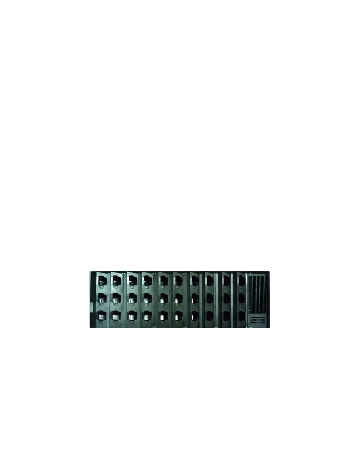
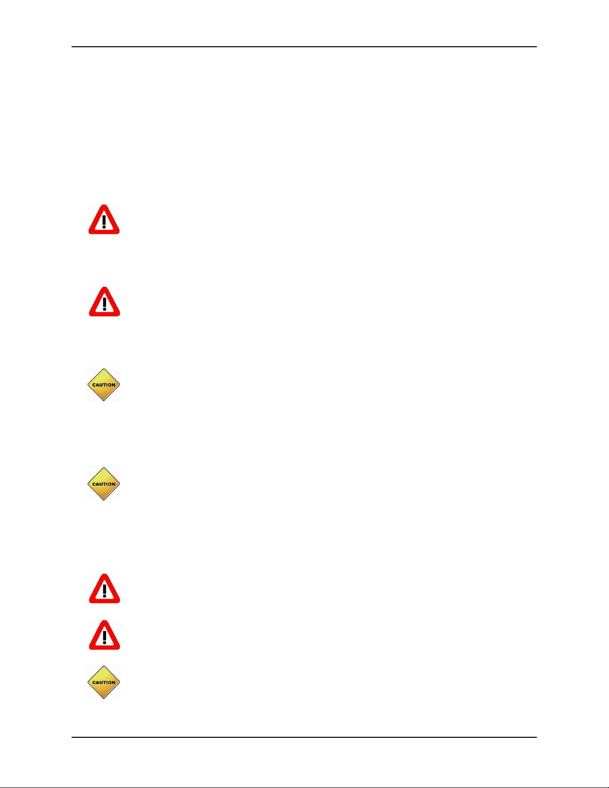
DIAD 6 Charge Rack
The Charge Rack holds and charges the DIAD 6s. Each rack can contain up to thirty DIAD 6s.
The DIAD 6 Charge Rack has the same exact footprint as the DIAD 5 Charge Rack, permitting
quick installation and replacement of existing hardware.
DIAD 6 Charge Rack Wall Mounting Frame
A mounting frame is used to wall mount the Charge Rack on a variety of materials and surfaces.
The mounting frame has a large number of slots open that allow maximum flexibility in meeting a
variety of installation conditions.
DCS
DCS (DIAD Communication System) is a software program that runs on a computer within the
operating center. This program controls the upload/download of the DIADs, queries and reports,
and communication with other networked systems such as GTS, DIALs, etc.
DIAD Server
The software program allows the DCS program to communicate with the DIAD 6s utilizing an
802.11 wireless network.
Page 6
Introduction
1-2
DIAD 6 Charge Rack Manual
How to Use this Manual
The following icons are used in this manual to identify special safety and operational concerns.
The WARNING icon identifies conditions or practices that could result in per-
sonal injury or loss of life.
The CAUTION icon identifies conditions or practices that could result in damage
to the equipment or other property.
The NOTE icon is used to identify a special note or reminder.
The APPROVED icon is used to identify an approved and recommended procedure.
Page 7
Specifications
2-1
DIAD 6 Charge Rack Manual
Specifications
Dimensions
Height
15 1/4 inches (387 mm)
Width
47 3/4 inches (1213 mm)
Depth
6 3/4 inches (171 mm)
Depth (with Terminals and Side Guards)
11 inches (279 mm)
Weight
Without DIADS
61.0 lbs (27.7 kg)
With Side Guards
68.2 lbs (30.9 kg)
With Side Guards and DIADS (30)
107.5 lbs (48.8 kg)
Input Power
Input Voltage
90 - 264 VAC; 47 - 63 Hz
Current
3.5A @ 115VAC; 1.75A@230VAC
* Only 120 VAC 60Hz is approved for use in the United States (UL Listed) and Canada (CSA Certified).
Temperature Range
Operating Range
32 - 95°F (0 - 35°C)
Required Installation Location
In an office or climate-controlled environment that has a temperature range
between 45°F and 85°F (7° and 29°C).
RF Specification
Operating Frequency
144KHz
Max. TX H-field
The ambient temperature of the mounting location must remain between 32° F
and 95° F (0° C and 35° C). Charging is not guaranteed if the ambient temperature exceeds these limits.
Page 8
Specifications
2-2
DIAD 6 Charge Rack Manual
Model and Serial Numbers
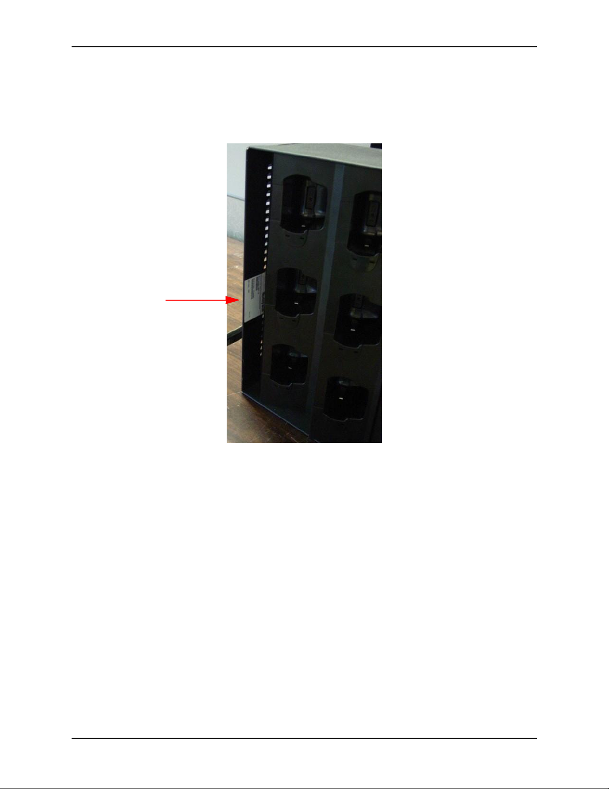
A label is located on the far left side of the Charge Rack that contains the model and serial number.
Serial
Number
Label
Page 9
Safety
3-1
DIAD 6 Charge Rack Manual
Safety
This section identifies safety considerations involved in assembling and operating the DIAD 6
Charge Rack.
Grounding
• Avoid electric shock from any equipment used for the installation by sup-
plying power from a properly grounded outlet.
Hazardous Waste
• Dispose of waste products properly, according to district procedure and
federal, state and local regulations.
Environment
• This equipment is intended for installation in an area that is not normally sub-
ject to conductive dust or weather. Do not install near other equipment or
machines that routinely produce conductive dust. Temperature extremes will
affect the charging rates of the DIADs.
Power Cords
• The Charge Rack power must be supplied from a properly grounded outlet. The
power outlet must be near the equipment and easily accessible after the equipment is installed.
• Power strips and extension cords should not be used.
Servicing
• Do not remove panels or attempt to service this equipment unless you are
qualified to do so.
• After removing power from the rack, wait 15 minutes before servicing the
unit to avoid shock.
• Pinched cables could cause serious damage to equipment. Always be aware of
cable position while removing or replacing any parts.
Page 10

Safety
3-2
DIAD 6 Charge Rack Manual
Stability
• The Charge Rack must be firmly fastened to a wall with enough room remaining
to allow easy access.
Page 11
Installing the Charge Rack
4-1
DIAD 6 Charge Rack Manual
Installing the Charge Rack
Inspection of the DIAD 6 Charge Rack
The DIAD 6 Charge Rack will be shipped by Honeywell Scanning and Mobility, approximately
eight weeks prior to the center’s first day use of DIAD 6s. Upon arrival the shipment needs to be
inspected by Site/District coordinator for any shortages or damages.
Package Contents
Item (Quantity)
Part Number
DIAD 6 Charge Rack (1)
CN85-CR (wired)
CN85-WCR (wireless)
Power Cord, US, IEC 320-C13 (1)
77900506E (with ferrite PN 10008320 attached)
Side Guard Kit (1)
containing:
Right Guard Panel (1)
Left Guard Panel (1)
Screw 8-32x1/2” (4)
99EX-CR-NRGUARDKIT
Regulatory Sheet (1)
n/a
Reporting Shortages or Damages
Immediately report any problems with the shipment to the District TSG Manager. District TSG
should contact Julie Rutt via email (nat1jar@ups.com) with the following information:
• RRDDSLIC of the location that is missing equipment or received damaged parts.
• The serial number of the damaged/missing part(s).
• The tracking number for the missing/damaged equipment.
Page 12

Installing the Charge Rack
4-2
DIAD 6 Charge Rack Manual
Receiving Replacement Parts
To obtain replacement parts for defective Charge Rack components, please refer to the following
web site for information regarding part numbers and costs:
http://wss.inside.ups.com/sites/CRA/syse/Projects/DIAD V/Troubleshooting, FAQ, and
Procedures/DIAD V Accessories and Charging Rack Part List.pdf
Charge Rack Installation
Scheduling the Installation
TSG, Plant Engineering, and the operating center need to coordinate the optimum time for Charge
Racks to be installed utilizing the locations that were determined during the wireless site survey
conducted by TSG. It is imperative that the DIAD 6 Charge Racks are installed in accordance with
the location determined in the wireless site survey.
Installation can occur well before scheduled DIAD 6 deployment provided the users can be provided a safe place to put spare DIAD 5 racks until the cutover to DIAD 6 takes place. A number
of DIAD 5 Charge Racks will remain in place to support the peak DIAD population.
Installation Methods
There are several methods to install the DIAD 6 Charge Rack:
• Remove the DIAD 5 Net Racks and replace them with the DIAD 6 Charge Racks.
or...
• Install DIAD 6 Charge Racks utilizing new mounting hardware in accordance with the loca-
tions agreed on during the wireless site survey conducted by TSG.
• Do not install near other equipment or machines that routinely produce conduc-
tive dust.
• DIAD 6 battery charging can be negatively affected by temperature extremes.
• A fully loaded DIAD 6 Charge Rack weighs 107.5 lbs (48.8 kg). The DIAD 6
must be installed in a location that will support the weight of the racks when
fully loaded.
• Vertical mounting of the Charge Rack is not recommended.
• The DIAD 6 Charge Rack should be installed in an interior location or climate-
controlled environment that is not subject to excessive dust or moisture and is
out of direct sunlight.
• The ambient temperature of the mounting location for DIAD 6 Charge Racks
must remain between 32° F and 95° F (0° C and 35° C). Charging is not guaranteed if the ambient temperature exceeds these limits.
Unpacking and Preparing the Work Area
This section explains how to unpack items and prepare the work area before assembling the
Charge Rack. All Charge Rack parts, hardware, and tools must be close to the work area.
Page 13

Installing the Charge Rack
4-3
DIAD 6 Charge Rack Manual
Requirements
All DIAD Charge Rack shipping containers and kits must be present. All required tools must be
present. Refer to the following section for the list of required tools depending on the type of
installation required.
• The DCS computer MUST have all programs shut down and the computer
MUST be powered off prior to disconnecting any DIAD 5 Charge Racks.
• Failure to do this will result in instability in the computer and will require TSG
intervention.
Procedure
1. Lay out and organize your tools in a clear area, preferably on an empty bench or table close to
the work area.
2. Organize the containers of the various Charge Rack components for easy access. Place them
at a comfortable distance so that unpacking them does not interfere with your work area.
3. Open all boxes and shipping containers. Take an inventory of the items received. Inspect hard-
ware for damage. DIAD 6 equipment questions (damages, shortages, overages, and/or incorrect serial numbers received) should be emailed by district coordinator to Julie Rutt via email
(nat1jar@ups.com). Please specify Region, District, SLIC and the serial numbers of any discrepancies.
4. Lay the units out in their intended locations to determine if any problems exist before installa-
tion, paying special attention to power cord lengths.
Replacement Charge Rack Installation
This section describes how to remove the existing DIAD 5 Charge Racks and replace with new
DIAD 6 Charge Racks. The DIAD 6 Charge Rack is designed for horizontal wall mounting only.
It has been manufactured to be a direct replacement to the existing DIAD 5 Charge Racks. The
DIAD 5 and DIAD 6 Charge racks have the same footprint making utilization of existing mounting hardware possible.
• Do not install near other equipment or machines that routinely produce conduc-
tive dust.
• DIAD 6 battery charging can be negatively affected by temperature extremes.
• A fully loaded DIAD Charge Rack weighs 107.5 lbs (48.8 kg). The DIAD 6 and
DIAD 5 Charge Racks must be installed in a location that will support the
weight of the racks when fully loaded.
Page 14
Installing the Charge Rack
4-4
DIAD 6 Charge Rack Manual
• The DIAD 6 Charge Rack must be installed in an interior location or climate-
controlled environment that is not subject to excessive dust or moisture and is
out of direct sunlight.
• The ambient temperature of the mounting location for DIAD 6 Charge Racks
must remain between 32° F and 95° F (0° C and 35° C). Charging is not guaranteed if the ambient temperature exceeds these limits.
Required Parts and Hardware
The DIAD 6 Charge Rack Kit contains a Charge Rack and two side guards with sheet metal
screws. The kit does not contain the four mounting bolts required. Use the existing bolts from
your uninstall. The DIAD 6 Charge Rack is designed to mount on the previously installed DIAD 5
mounting frame.
Item (Quantity)
Part Number
DIAD 6 Charge Rack (1)
CN85-CR (wired)
CN85-WCR (wireless)
Side Guard Kit (1)
99EX-CR-NRGUARDKIT
Tools
Before attempting to install the DIAD Charge Rack, you must have the following tools:
• 9/16” Wrench or socket
• Tape Measure
• Level
• Large Straight Blade Screwdriver
• Small Straight Blade Screwdriver
• Phillips Screwdriver
Replacement Installation Procedure
1. Locate the existing DIAD 5 Charge Racks within the facility. Ensure the Charge Rack is
empty of DIAD units. Have UPS operations remove all existing DIAD 5s. Locate the ON/
OFF toggle switch on the Charge Rack and turn to OFF. Unplug unit from electrical outlet.
Disconnect all data cables from the unit using a small straight blade screwdriver and cover the
cable ends with electrical tape.
2. Remove the top cover from the Base Station by unsnapping cover from slots located near rear
wall of Base Station. For stacked multiple Base Station mountings, remove mid cover and
upper Base Station and pry loose.
3. The following steps are easier to perform with two people. One person should hold the exist-
ing Base Station while the second person loosens the four 3/8-16 x 1” Hex Head Screws and
3/8” x 1 flat washers from the Base Station. Screws and washers are located on the vertical
Page 15

Installing the Charge Rack
4-5
DIAD 6 Charge Rack Manual
plane of the back area of the Base Station at DIAD slot 4 and 12. Upon removal of screws, lift
Base Station and remove.
4. With the existing Base Station removed, check the condition of existing mounting brackets.
Ensure both the top and bottom u-channel brackets are level, square and properly secured to
wall. Check the condition and alignment of the u-channel spring nut. Properly align the
existing four u-channel spring nuts to the match hole in the new DIAD 6 Charge Rack. Coil
the existing communication cable and secure it away from the new Charge Racks. Coordinate
with local Plant Engineering and TSG on the complete removal of cabling, if possible. Centers will no longer use DIAD 5 Charge Racks. DIAD 6 will become the peak device in all
centers where DIAD 6 is deployed. DIAD 5 racks should be disposed of in accordance with
established procedures.
5. Lift the new DIAD 6 Charge Rack into place on the existing mounting frame so that the tabs
on the back of the Charge Rack support the weight during installation.
The Charge Rack must be fastened to the wall with the hardware removed in Step 3.
DO NOT use tabs to permanently mount the Charge Rack.
Page 16
Installing the Charge Rack
4-6
DIAD 6 Charge Rack Manual
6. Use a Phillips screwdriver to remove the screws from the six-port charge bay on the right side
of the Charge Rack and then remove the screws from the six-port charge bay on the left side of
the Charge Rack.
Pull the bay out
and rotate it to
the right to
access cables.
CN85-CR (Wired)
CN85-WCR (Wireless)
Page 17
Installing the Charge Rack
4-7
DIAD 6 Charge Rack Manual
7. Pull each six-port charge bay forward and disconnect the power cord to expose the mounting
holes. Be sure to retain your Phillips screws to reinstall the six-port charge bays after the rack
has been mounted.
Disconnect the power
supply harness from the
power distribution
board and set the bays
aside in a clean work
area.
Page 18
Installing the Charge Rack
4-8
DIAD 6 Charge Rack Manual
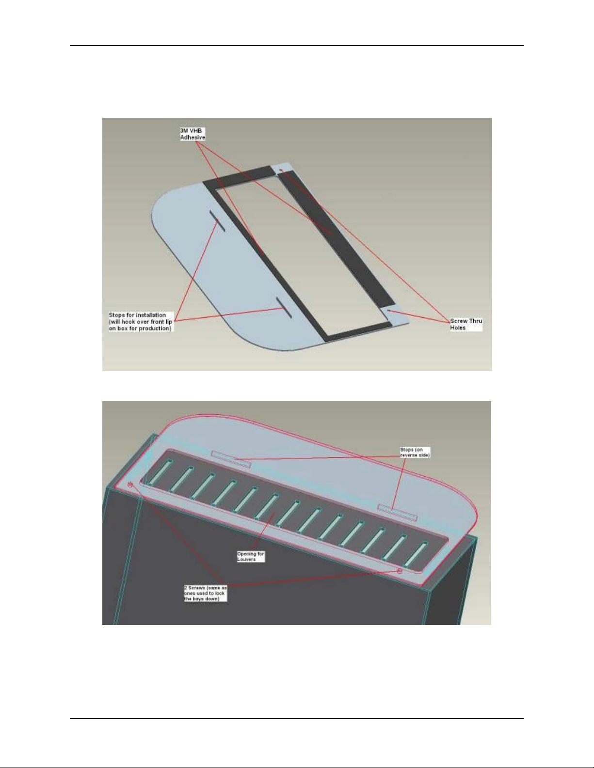
8. Attach the side guard rails to each side of the DIAD 6 Charge Rack using two Phillips screws
and the 3M adhesive strips supplied with each guard rail.
DIAD 6 Rack left side rail
Left facing side rail/rack mounting position
Page 19
Installing the Charge Rack
4-9
DIAD 6 Charge Rack Manual
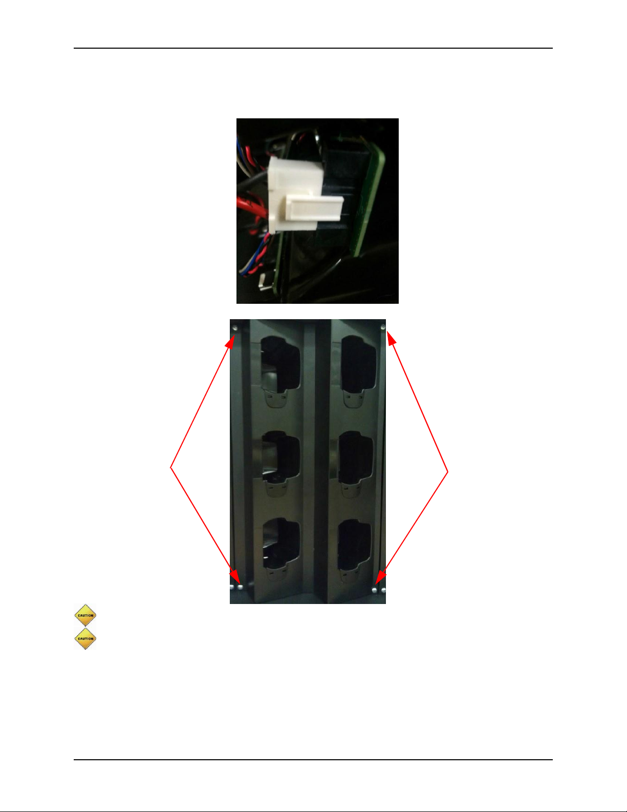
9. Insert the four 3/8” x 1” Hex Head bolts through the 3/8” x 1 flat washers. Then place through
the mounting holes in sections one and five of the Charge Rack and into the u-channel spring
nut. Hand-tighten and repeat for all four locations, then torque down all bolts to 40 in lbs. with
appropriate wrench or socket. Use care not to over-torque the bolts. Check to make sure the
Charge Rack is level.
Charge Rack Mounting Holes
Page 20
Installing the Charge Rack
4-10
DIAD 6 Charge Rack Manual
10. Reconnect the power cables to the six-port charge bays and reinstall them with the Phillips
head screws retained earlier.
Screws
Screws
Do not pinch wires during reinstallation as this may damage the equipment.
Be careful not to over-tighten the screws, which could damage the 6-Slot Bay and prevent
the component from being adequately secured.
Page 21
Installing the Charge Rack
4-11
DIAD 6 Charge Rack Manual
New Charge Rack Installation
• Do not install near other equipment or machines that routinely produce conduc-
tive dust.
• DIAD 6 battery charging can be negatively affected by temperature extremes.
• A fully loaded DIAD 6 charge rack weighs 107.5 lbs (48.8 kg). The DIAD 6
Charge Racks must be installed in a location that will support the weight of the
racks when fully loaded.
• The Mounting Frame MUST be used to secure the DIAD 6 Charge Rack to the
wall to prevent possible damage to the Charge Rack. Failing to use the Mounting Frame could result in issues charging/powering terminals within the rack.
• The DIAD 6 Charge Rack should be installed in an interior location that is not
subject to excessive dust or moisture and is out of direct sunlight.
• The ambient temperature of the mounting location for DIAD 6 Charge Racks
must remain between 32° F and 95° F (0° C and 35° C). Charging is not guaranteed if the ambient temperature exceeds these limits.
This section describes how to mount the DIAD 6 Charge Rack where no rack was previously
installed. The DIAD 6 Charge Rack is designed for horizontal wall mounting only. The mounting
frame attaches to a wall that can structurally support the DIAD 6 Charge Rack. The mounting
frame must be attached to structural supports within the wall. The DIAD 6 Charge Rack fastens to
the mounting frame.
Required Parts and Hardware
All parts required to assemble DIAD 6 Charge Rack systems are pre-package as assembled
groups or as bagged parts.
Item (Quantity)
Part Number
DIAD 6 Charge Rack Kit (1)
(kit does not contain 4 mounting bolts)
CN85-CR (Wired)
CN85-WCR (Wireless)
Side Guard Kit (1)
99EX-CR-NRGUARDKIT
Wall Mount Frame (1)
By Local P.E.
Channel Frame 3/8” Nut w/retainer (4)
By Local P.E.
1/8” - 16 1” Hex Head Screw (4)
By Local P.E.
3/8” - 2.5” Hex Lag Screw (6)
By Local P.E.
5/16” Toggle Bolt (4)
By Local P.E.
0.375”x1.6”x 0.125” Fender Washer (4)
By Local P.E.
0.265”x8.875”x 0.035” Fender Washer (4)
By Local P.E.
Page 22

Installing the Charge Rack
4-12
DIAD 6 Charge Rack Manual
Item (Quantity)
Part Number
4/8”x1”x14 ga. Flat Washer (10)
By Local P.E.
1/4” Molly Bolt (4)
By Local P.E.
Use Existing Bolts from DIAD 5 Uninstall
From Uninstall
Tools
Before attempting to install the DIAD Charge Rack, you must have the following tools:
• 1/8” Blade, 2” Shaft Screwdriver
• 3/8” Drill and Appropriate Bit (see page 4-15)
• 9/16” Wrench or Socket
• Tape Measure
• Level
• Stud Sensor
• Large Straight Blade Screwdriver
• Phillips Screwdriver
Page 23
Installing the Charge Rack
4-13
DIAD 6 Charge Rack Manual
New Installation Procedure
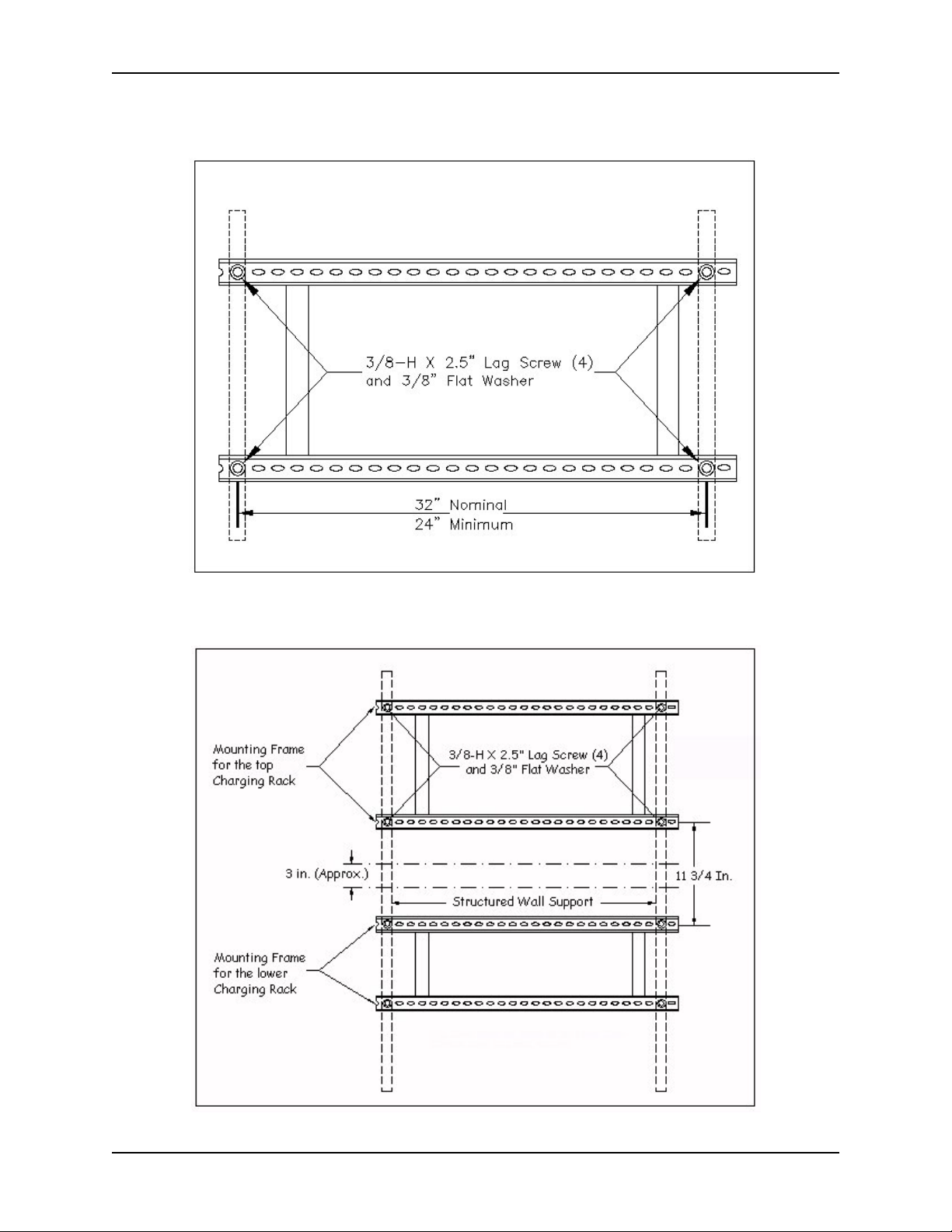
1. Determine the best mounting location for the installation. Check for the proper length from
the Charge Rack to a power outlet. Allow sufficient space above the Charge Rack; minimum
clearance between Charge Racks is 3 inches. In addition, allow sufficient space to the right of
the Charge Rack to access the electrical connections. The Charge Rack will extend 2 1/4
inches past the end of the mounting frame on both ends.
Charge Rack Installation Specifications
2. Identify the locations of the structural supports within the wall designated for mounting the
Charge Rack. Plant Engineering should verify and mark the correct structural mounting location.
3. The following steps are easier to perform with two people: one person should hold the mount-
ing frame in place while the second person checks to make sure it is level and marks the hole
locations with the tip of a mounting screw, pencil, or pen. Two or more screws support each
channel of the mounting frame. If a second person is not available, use the mounting template
to mark the mounting hole locations. Failing to install a mounting frame could damage the
Charge Rack and result in issues charging/powering terminals located within the Charge
Rack.
Check with the responsible plant management group before drilling any holes
through walls. Extreme caution should be used to avoid contacting power lines.
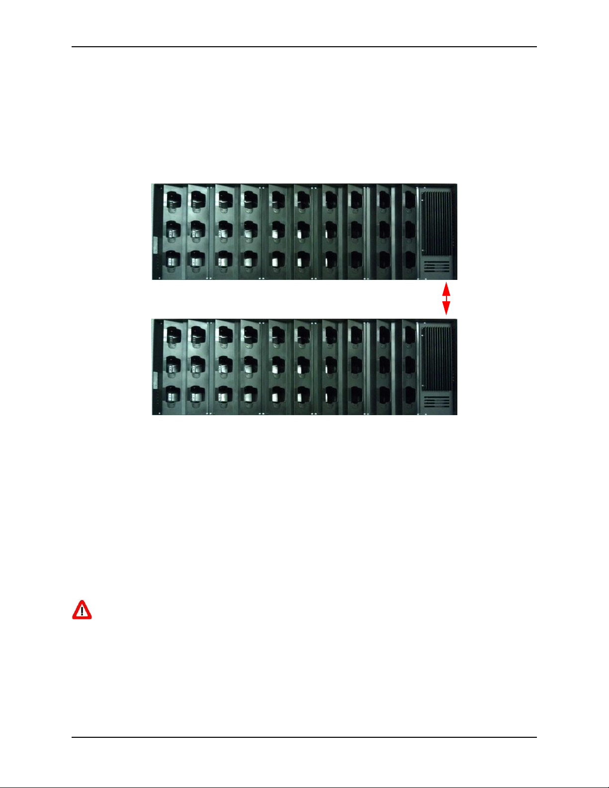
Minimum distance between mounted DIAD 6 Charge Racks
is 3” (7.62 CM)
Page 24
Installing the Charge Rack
4-14
DIAD 6 Charge Rack Manual
Single Charge Rack Install
Single Charge Rack Mounting Specifications
Multiple Charge Rack Install
Multiple Charge Rack Mounting Specifications
Page 25

Installing the Charge Rack
4-15
DIAD 6 Charge Rack Manual
4. Make an indentation or small hole in the intended hole locations. Drill an appropriate hole
through the wall for each of the two, or more, 3/8” lag mounting screws. Refer to the following table for the appropriate drill size for the wall materials encountered. Make sure that the
holes have penetrated the structural wall supports.
Hardware Mounting Recommendations
Inner Wall Material
Drill Sizes
Hardware
Washer
Wood
9/32” (0.281”) x 1/5” deep
Lag Screw
3/8” Flat
Steel (with hollow
wall)
7/16” (0.437”)
1/4” Molly Bolt of the
Appropriate Length*
0.265”x 0.875”
Fender
Cinder Block
7/16” (0.437)
1/4” Molly Bolt of the
Appropriate Length
0.265”x 0.875”
Fender
7/8” (0.875”)
5/16” Toggle Bolt**
3/8” Flat
Concrete, Solid
As Required
Lead Anchors
As Required
*For walls 5/8” to 1 - 1/4” thick
** Do not remove the bolts after inserting them into the wall.
5. One person should hold the mounting frame in place while the second person screws the 3/8”
lag screws and 3/8” flat washers into the prepared hold locations. Prior to tightening the
screws completely, check that the mounting frame is level. Adjust as necessary and complete
tightening the wall mounting screws.
Install all mounting frames with the sheared end (incomplete or partial right side) to
ensure that the mounting hole locations align properly. This is especially critical in multiple stacked installations.
Page 26

Installing the Charge Rack
4-16
DIAD 6 Charge Rack Manual
6. Insert the channel frame nut with the retainer into the channel frame where the Charge Rack
mounting hardware will be inserted, (see the following figure.) Insert the right nut with
retainer 6 3/4 inches from the right end of each channel. The center of the left nut with
retainer is installed 30 inches from the center of the right nut. Marking the front of the channel makes installation easier. These measurements will allow the Charge Rack to be installed
centered on the mounting frame. The channel frame nuts can be installed to the left or right of
these measurements if necessary. Keep in mind that access to the power cord is on the right
side of the Charge Rack. This is especially important in a stacked installation.
Attaching Charge Rack to Wall Mount Frame
Page 27

Installing the Charge Rack
4-17
DIAD 6 Charge Rack Manual
7. Use a Phillips screwdriver to remove the screws from the six-port charge bay on the right side
of the Charge Rack and then remove the screws from the six-port charge bay on the left side of
the Charge Rack.
Pull the bay out
and rotate it to
the right to
access cables.
CN85-CR (Wired)
CN85-WCR (Wireless)
Page 28

Installing the Charge Rack
4-18
DIAD 6 Charge Rack Manual
8. Pull each six-port charge bay forward and disconnect the power cord to expose the mounting
holes. Be sure to retain your Phillips screws to reinstall the six-port charge bays after the rack
has been mounted.
Disconnect the power
supply harness from the
power distribution
board and set the bays
aside in a clean work
area.
9. Install the side guard rails. Attach the side guard rails to each side of the DIAD 6 Charge Rack
using 2 Phillips screws and the 3M adhesive strips supplied with each guard rail.
DIAD 6 Rack left side rail
Page 29

Installing the Charge Rack
4-19
DIAD 6 Charge Rack Manual
Left facing side rail/rack mounting position
The Charge Rack must be fastened to the wall with the approved hardware. DO
NOT use the tabs to permanently mount the Charge Rack.
10. Lift the Charge Rack into place on the mounting frame so that the tabs on the back of the
Charge Rack support the weight during installation.
Insert the four 3/8” x 1” Hex Head bolts through the 3/8” x 1 flat washers. Then place through
the mounting holes in sections one and four of the Charge Rack and into the u-channel spring
nut. Hand-tighten and repeat for all four locations, then torque down all bolts to 40 in lbs. with
appropriate wrench or socket. Use care not to over torque the bolts. Check to make sure the
Charge Rack is level. Plug the power cord into the existing power source.
Charge Rack Mounting Holes
Page 30

Installing the Charge Rack
4-20
DIAD 6 Charge Rack Manual
11. Reconnect the power cables to the six-port charge bays and reinstall them with the Phillips
head screws retained earlier.
Screws
Screws
Do not pinch wires during reinstallation as this may damage the equipment.
Be careful not to over-tighten the screws, which could damage the 6-Slot Bay and prevent
the component from being adequately secured.
Page 31

Using the Charge Rack
5-1
DIAD 6 Charge Rack Manual
Using the Charge Rack
Overview
You can power and charge the main battery in up to thirty DIAD 6 terminals using the Charge
Rack.
Charge Time
The rack supplies power to the intelligent battery charging system in all DIAD 6 terminals, which
senses when a full charge has been achieved and switches to a trickle charge to maintain the full
charge. As battery packs charge, the charging circuitry follows the two-step charging process
(CC-CV) that is recommended for Li-ion or Li-poly batteries. The process monitors changes in
temperature, current, and voltage.
The rack completes a full charge of the DIAD 6’s main battery pack in 6 hours.
Convenient Storage
Intelligent battery charging makes this rack a safe and convenient storage receptacle for your
DIAD 6 terminal.
Capacity
The rack can hold up to thirty DIAD 6 terminals. Each charging well charges each terminal inde-
pendently of the other wells.
Parts and Functions
Front and Side Panel
AC Power
Jack
30 Terminal Wells
Page 32

Using the Charge Rack
5-2
DIAD 6 Charge Rack Manual
Side Guard
Power Supply End
Non-Power Supply End
Terminal Wells
The rack contains thirty terminal wells. Place the DIAD 6 terminal in any one of the thirty wells to
power the terminal and charge the installed battery pack. The rack completely charges the main
battery in a DIAD 6 terminal in 6 hours.
AC Power Jack
Use the AC power cable that comes with the rack to supply power to this power jack. For more
information, see Power on page 5-2.
A locally procured power cable is required for use outside the United States.
Power
The rack requires 90 - 264 Volts AC, 3.5 Amps at 115 Volts to charge the DIAD 6 terminals. We
recommend that you leave the rack connected to its power source at all times, so that it is always
ready to use.
Connecting Power to the Rack
1. Plug the power cable into the power connector on the side of the rack, see AC Power Jack on
page 5-2.
2. Plug the AC power cord into a standard wall outlet. The rack is now powered.
Power strips and extension cords should not be used.
Page 33

Using the Charge Rack
5-3
DIAD 6 Charge Rack Manual
Charging the Main Battery
The rack provides power to the DIAD 6 terminals and
allows the charging of the main batteries in the terminal. The intelligent battery charging system incorporated into all DIAD 6 terminals prevents
overcharging, which means that DIAD 6 terminals
may be stored in the rack indefinitely without damage
to the terminals, battery packs, or the rack.
The rack supports a reduced power output to each terminal to allow simultaneous charging of all 30 units
across the full temperature specification. The terminal will automatically reduce its power consumption
in the rack by turning off its display and backlight. To
communicate with the terminal, use the WLAN radio
for the Charge Rack. The application software should
turn off all other radios and features. If not, the operating temperature range may be reduced and/or the
power supply overloaded, which may result in an
extended charge time or no charging.
To Power a Terminal and Charge its Main Battery
1. Install the main battery pack in the terminal.
2. Slide the DIAD 6 terminal into one of the thirty terminal wells. The terminal screen turns off
immediately when docked to conserve power. Charging begins immediately if required by the
DIAD 6 terminal.
Charging Status Through Notification LEDs
The terminal will indicate the charging status through the notification LEDs at the top of the ter-
minal. The LEDs operate as follows:
Solid Orange
Indicates that the terminal is docked in the rack and the battery is being
charged.
Solid Green
Indicates that the terminal is fully charged.
Solid Red
Indicates that the terminal is docked in the rack and receiving power,
but the battery appears to be worn out or defective.
Blinking Orange
Indicates that the terminal is docked and receiving power but is not
charging because the battery is too hot or too cold.
Off
Indicates that the terminal is not docked in the rack, the terminal is
defective, the rack is defective, or the rack is not receiving power.
Page 34

Using the Charge Rack
5-4
DIAD 6 Charge Rack Manual
This page left blank.
Page 35

Part Replacement Procedures
6-1
DIAD 6 Charge Rack Manual
Big Harness - 200004056CNRKIT
Part Replacement Procedures
Big Harness - 200004056CNRKIT
Part Name:
Big Harness
Part #:
200004056CNRKIT
Tools Required:
1 medium #2 Phillips head screw driver
Before working on the Charge Rack, always disconnect the AC cord from the power
supply.
After removing power, wait 15 minutes before servicing the unit to avoid shock.
Isolate screws by size as you remove them to ensure proper placement when reinstalling.
1. Disconnect the AC cord from the power supply.
Power
Supply
Page 36

Part Replacement Procedures
6-2
DIAD 6 Charge Rack Manual
Big Harness - 200004056CNRKIT
2. Remove the two screws from the power supply. Retain the screws for installation.
Screws
3. Pull the power supply straight out by holding onto the heat sink.
Heat Sink
Page 37

Part Replacement Procedures
6-3
DIAD 6 Charge Rack Manual
Big Harness - 200004056CNRKIT
4. Support the power supply with one hand and disconnect the main plug. Set the unit aside in a
clean work area.
Main
Plug
Support the
power supply
with one hand
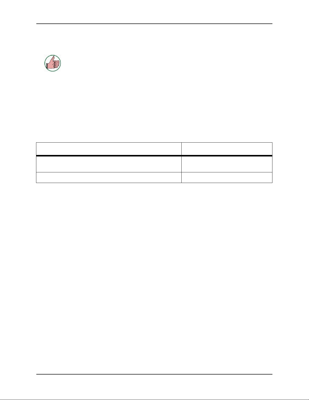
5. Remove each of the six-slot terminal bays (there are five bays). Begin by removing the four
mounting screws that hold the bay to the sheet metal enclosure. Retain the screws for installation.
Screws
Screws
Page 38

Part Replacement Procedures
6-4
DIAD 6 Charge Rack Manual
Big Harness - 200004056CNRKIT
6. Pull the bay out and rotate it to the right to access the cables.
CN85-CR (Wired)
CN85-WCR (Wireless)
Page 39

Part Replacement Procedures
6-5
DIAD 6 Charge Rack Manual
Big Harness - 200004056CNRKIT
7. Disconnect the power supply harness from the power distribution board.
8. Repeat steps 5-7 for the four remaining bays.
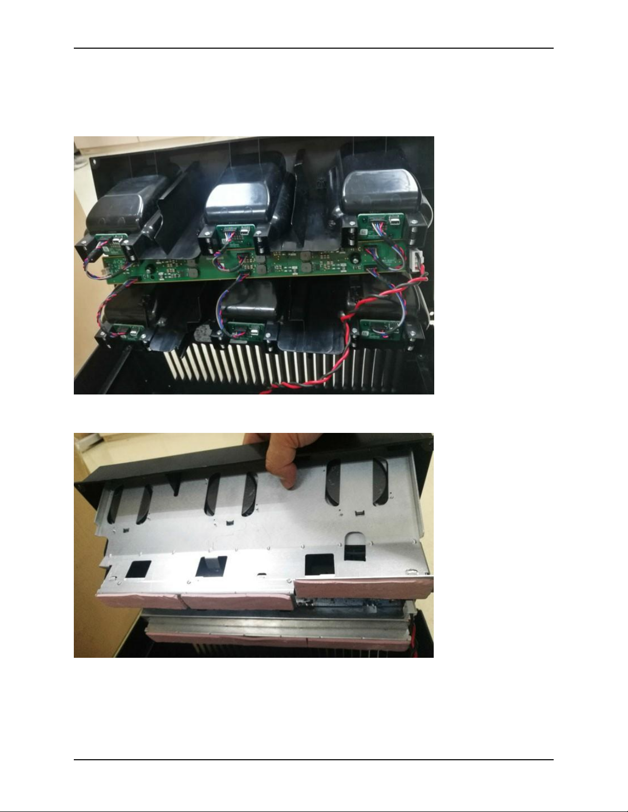
9. To remove the big harness, begin by cutting the zip ties holding the harness to the sheet metal
frame.
zip ties
Page 40

Part Replacement Procedures
6-6
DIAD 6 Charge Rack Manual
Big Harness - 200004056CNRKIT
10. Place the new harness into the wiring channel in the rear of the enclosure and add the zip ties
that were provided in the kit.
Page 41

Part Replacement Procedures
6-7
DIAD 6 Charge Rack Manual
Big Harness - 200004056CNRKIT
Don’t forget
to pull each
lead out for
each bay.
Wiring Channel
Page 42

Part Replacement Procedures
6-8
DIAD 6 Charge Rack Manual
Big Harness - 200004056CNRKIT
11. Take the bay to the rack.
CN85-CR (Wired)
CN85-WCR (Wireless)
Page 43

Part Replacement Procedures
6-9
DIAD 6 Charge Rack Manual
Big Harness - 200004056CNRKIT
12. Connect the power cable.
Do not pinch wires during reinstallation as this may damage the equipment
13. Re-install the bay using the four mounting screws.
Screws
Screws
Be careful not to over-tighten the screws, which could damage the 6-Slot Bay and prevent
the component from being adequately secured.
14. Repeat steps 11-13 for the other four bays.
Page 44

Part Replacement Procedures
6-10
DIAD 6 Charge Rack Manual
Big Harness - 200004056CNRKIT
15. Take the power supply to the Charge Rack and connect the main plug.
Do not pinch wires during reinstallation as this may damage the equipment.
Page 45

Part Replacement Procedures
6-11
DIAD 6 Charge Rack Manual
Big Harness - 200004056CNRKIT
16. Remount the power supply into place.
Page 46

Part Replacement Procedures
6-12
DIAD 6 Charge Rack Manual
Big Harness - 200004056CNRKIT
17. Using the heat sink, place the power supply back into the main unit.
Heat Sink
18. Re-install the two screws.
Screws
Page 47

Part Replacement Procedures
6-13
DIAD 6 Charge Rack Manual
Big Harness - 200004056CNRKIT
19. The installation should be complete. Re-install the AC cord and test for functionality.
Page 48

Part Replacement Procedures
6-14
DIAD 6 Charge Rack Manual
Big Harness - 200004056CNRKIT
This page left blank.
Page 49

Part Replacement Procedures
6-15
DIAD 6 Charge Rack Manual
NyoGel® 760G Lubricant Procedure
NyoGel® 760G Lubricant Procedure
1. Remove power from the Charge Rack.
2. Remove all screws of the six-slot terminal bay. Retain the screws for installation.
Screws
Screws
3. Disassemble the cable from the power distribution board. by pulling the bay out and rotating it
to the right to access the cables.
CN85-CR (Wired)
Page 50

Part Replacement Procedures
6-16
DIAD 6 Charge Rack Manual
NyoGel® 760G Lubricant Procedure
CN85-CR (Wired)
4. Disconnect the power supply harness from the power distribution board.
Page 51

Part Replacement Procedures
6-17
DIAD 6 Charge Rack Manual
NyoGel® 760G Lubricant Procedure
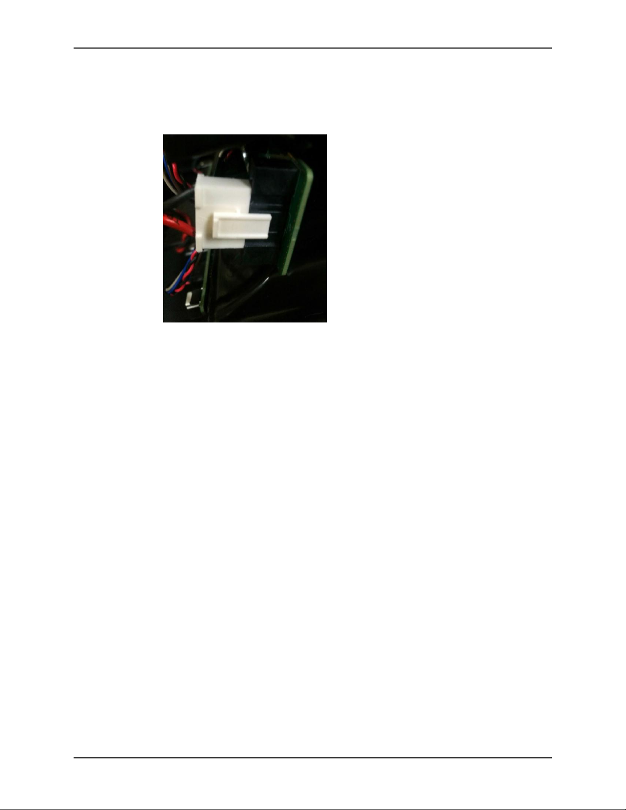
5. Fully fill the first and fourth positions of the connector with NyoGel lubricant.
6. Insert the wire harness into the board connector.
Page 52

Part Replacement Procedures
6-18
DIAD 6 Charge Rack Manual
NyoGel® 760G Lubricant Procedure
7. Re-install the bay using the four mounting screws.
Screws
Screws
8. Stick the “Lubricant Applied” label on the rack as indicated below.
Page 53

Part Replacement Procedures
6-19
DIAD 6 Charge Rack Manual
I/O Board Cable - 50142485-001FRE
I/O Board Cable - 50142485-001FRE
Part Name:
I/O Board Cable
Part #:
50142485-001FRE
Tools Required:
1 medium #2 Phillips head screw driver
Before working on the Charge Rack, always disconnect the AC cord from the power
supply.
After removing power, wait 15 minutes before servicing the unit to avoid shock.
1. Remove the 6-slot bay from the Charge Rack.
2. There are 6 cables on the 6-slot bay. Disconnect the broken one and replace it with the new
cable.
3. Reload the 6-slot bay into the Charge Rack.
Do not pinch wires during reinstallation as this may damage the equipment
Be careful not to over-tighten the screws, which could damage the 6-Slot Bay and prevent
the component from being adequately secured.
Page 54

Part Replacement Procedures
6-20
DIAD 6 Charge Rack Manual
I/O Board Cable - 50142485-001FRE
This page left blank.
Page 55

Part Replacement Procedures
6-21
DIAD 6 Charge Rack Manual
I/O Board - 50142380-001FRE
I/O Board - 50142380-001FRE
Part Name:
I/O Board
Part #:
50142380-001FRE
Tools Required:
1 medium #2 Phillips head screw driver
Before working on the Charge Rack, always disconnect the AC cord from the power
supply.
After removing power, wait 15 minutes before servicing the unit to avoid shock.
Isolate screws by size as you remove them to ensure proper placement when reinstalling.
1. Remove the 6-slot bay from the Charge Rack.
2. Disconnect the cable between the I/O board and the power board.
3. Remove the two screws between the board and the bays.
Page 56

Part Replacement Procedures
6-22
DIAD 6 Charge Rack Manual
I/O Board - 50142380-001FRE
4. Separate the board from the bay.
5. Replace the broken board with the new one.
6. Reload the 6-slot bay into the Charge Rack.
Do not pinch wires during reinstallation as this may damage the equipment
Be careful not to over-tighten the screws, which could damage the 6-Slot Bay and prevent
the component from being adequately secured.
Page 57

Part Replacement Procedures
6-23
DIAD 6 Charge Rack Manual
Power Distribution - Board 50142378-001FRE
Power Distribution - Board 50142378-001FRE
Part Name:
Power Distribution Board
Part #:
50142378-001FRE
Tools Required:
1 medium #2 Phillips head
screw driver
Before working on the Charge Rack, always disconnect the AC cord from the power
supply.
After removing power, wait 15 minutes before servicing the unit to avoid shock.
Isolate screws by size as you remove them to ensure proper placement when reinstalling.
1. Remove the 6-slot bay from the Charge Rack.
2. Disconnect the 6 cables from the I/O board.
3. Remove the two screws between the power board and the 6-slot bay.
4. Separate the power board from the bay.
5. Replace the broken board with the new one.
Page 58

Part Replacement Procedures
6-24
DIAD 6 Charge Rack Manual
Power Distribution - Board 50142378-001FRE
6. Reload the 6-slot bay into the Charge Rack.
Do not pinch wires during reinstallation as this may damage the equipment
Be careful not to over-tighten the screws, which could damage the 6-Slot Bay and prevent
the component from being adequately secured.
Page 59

Part Replacement Procedures
6-25
DIAD 6 Charge Rack Manual
Power Supply with PS-Harness Assembly - 100008187CNRKIT
Power Supply with PS-Harness Assembly - 100008187CNRKIT
Part Name:
Charge Rack Power Supply with PSHarness Assembly
Part #:
100008187CNRKIT
Tools Required:
1 medium #2 Phillips head screw driver
Before working on the Charge Rack, always disconnect the AC cord from the power
supply.
After removing power, wait 15 minutes before servicing the unit to avoid shock.
1. Disconnect the AC cord from the power supply.
Power
Supply
Page 60

Part Replacement Procedures
6-26
DIAD 6 Charge Rack Manual
Power Supply with PS-Harness Assembly - 100008187CNRKIT
2. Remove the two screws from the power supply. Do not retain screws. (Use the screws pro-
vided in the kit for replacement.)
Screws
Page 61

Part Replacement Procedures
6-27
DIAD 6 Charge Rack Manual
Power Supply with PS-Harness Assembly - 100008187CNRKIT
3. Pull the power supply straight out by holding onto the heat sink.
Heat Sink
4. Support the power supply with one hand and disconnect the main plug. Set the unit aside in a
clean work area.
Main
Plug
Support the
power supply
with one hand
Page 62

Part Replacement Procedures
6-28
DIAD 6 Charge Rack Manual
Power Supply with PS-Harness Assembly - 100008187CNRKIT
5. Take the new power supply to the Charge Rack and connect the main plug.
Page 63

Part Replacement Procedures
6-29
DIAD 6 Charge Rack Manual
Power Supply with PS-Harness Assembly - 100008187CNRKIT
6. Remount the power supply into place.
Do not pinch wires during reinstallation as this may damage the equipment.
Page 64

Part Replacement Procedures
6-30
DIAD 6 Charge Rack Manual
Power Supply with PS-Harness Assembly - 100008187CNRKIT
7. Using the heat sink, place the power supply back into the main unit.
Heat Sink
8. Install the two new screws supplied in the kit.
Screws
Page 65

Part Replacement Procedures
6-31
DIAD 6 Charge Rack Manual
Power Supply with PS-Harness Assembly - 100008187CNRKIT
9. The installation of the power supply should be complete. Re-install the AC cord and test for
functionality.
Page 66

Part Replacement Procedures
6-32
DIAD 6 Charge Rack Manual
Power Supply with PS-Harness Assembly - 100008187CNRKIT
This page left blank.
Page 67

Part Replacement Procedures
6-33
DIAD 6 Charge Rack Manual
6-Slot Terminal Bay - 50143872-001FRE
6-Slot Terminal Bay - 50143872-001FRE
Part Name:
6-Slot Terminal
Part #:
50143872-001FRE
Tools Required:
1 medium #2 Phillips head screw driver
Before working on the Charge Rack, always disconnect the AC cord from the power
supply.
After removing power, wait 15 minutes before servicing the unit to avoid shock.
Isolate screws by size as you remove them to ensure proper placement when reinstalling.
1. Remove the 6-slot bay from the Charge Rack.
2. Disconnect the 6 cables between the I/O and power boards.
3. Remove all of the screws and then remove all of the boards.
4. Replace the 6-slot bay with the new one.
5. Install all boards and connect all of the cables on the 6-slot bay.
6. Reload the 6-slot bay into the Charge Rack.
Do not pinch wires during reinstallation as this may damage the equipment
Be careful not to over-tighten the screws, which could damage the 6-Slot Bay and prevent
the component from being adequately secured.
Page 68

6-34
DIAD 6 Charge Rack Manual
6-Slot Terminal Bay - 50143872-001FRE
This page left blank.
Page 69

6-35
DIAD 6 Charge Rack Manual
Part Replacement Procedures
Power Board (Wireless) - 50145763-001FRE
Power Board (Wireless) - 50145763-001FRE
Part Name:
Power Board (Wireless)
Part #:
50145763-001FRE
Tools Required:
1 medium #2 Phillips head screw driver
Before working on the Charge Rack, always disconnect the AC cord from the power
supply.
After removing power, wait 15 minutes before servicing the unit to avoid shock.
Isolate screws by size as you remove them to ensure proper placement when reinstalling.
1. Remove the 6-slot bay from the Charge Rack.
2. Remove the screws between the board and the frame.
Page 70

6-36
DIAD 6 Charge Rack Manual
Part Replacement Procedures
Power Board (Wireless) - 50145763-001FRE
3. Use a soldering tool to disconnect the soldering wires on the board.
4. Separate the board from the frame.
5. Replace the board with the new one and install the board into the 6-slot bays.
6. Reload the 6-slot bay into the Charge Rack.
Do not pinch wires during reinstallation as this may damage the equipment
Be careful not to over-tighten the screws, which could damage the 6-Slot Bay and prevent
the component from being adequately secured.
Page 71

6-37
DIAD 6 Charge Rack Manual
Part Replacement Procedures
Core Module (Wireless) - 50145761-001FRE
Core Module (Wireless) - 50145761-001FRE
Part Name:
Core Module (Wireless)
Part #:
50145761-001FRE
Tools Required:
1 medium #2 Phillips head screw driver
Before working on the Charge Rack, always disconnect the AC cord from the power
supply.
After removing power, wait 15 minutes before servicing the unit to avoid shock.
Isolate screws by size as you remove them to ensure proper placement when reinstalling.
1. Remove the 6-slot bay from the Charge Rack.
2. Remove the power board from the 6-slot bay.
3. Remove the silver screws between the frames. Please note that the screws are on both sides of
the frame.
Page 72

6-38
DIAD 6 Charge Rack Manual
Part Replacement Procedures
Core Module (Wireless) - 50145761-001FRE
4. Remove the black screws between the frames and plastic bay cover.
5. Remove the four screws between the coil module and the frame.
6. Replace the coil module with new one and re-install it on the frame.
7. Re-install the frame and power board on the 6-slot bay.
8. Reload the 6-slot bay into the Charge Rack.
Do not pinch wires during reinstallation as this may damage the equipment
Be careful not to over-tighten the screws, which could damage the 6-Slot Bay and prevent
the component from being adequately secured.
Page 73

Maintenance
7-1
DIAD 6 Charge Rack Manual
Maintenance
It is important to keep the outer case of the Charge Rack clean and free of debris. Regular cleaning will help prevent dirt from being transferred to the rack as well as protecting the terminal from
excess scratches and damage.
Cleaning
DO NOT:
•
DO NOT place coffee, soft drinks, or other materials in or on the Charge Rack.
•
DO NOT clean the Charge Rack with unapproved solvents.
•
DO NOT spray or pour cleaning solutions directly onto the equipment.
•
DO NOT use any pressure washers or hoses to clean the equipment.
DO:
•
Use only approved cleaning materials.
•
Clean the Charge Rack once a week.
•
Protect eyes when pouring or spraying the cleaning solution.
Approved Cleaner
• Plasti-Kleen* (Oasis PN 2200105656 or 490630)
• FilmFree* (Oasis PN 15361)
• Water
• Common dish soap and water
• Ammonia-free glass cleaner
• Thermal Printer Clean-Penn (Oasis PN 105950-035)
*Recommended cleaner.
Cleaning Procedure
1. Protect eyes when pouring or spraying solution.
2. Apply the cleaning solution to the cleaning towelette. DO NOT spray or pour the solution
directly onto the equipment. Avoid excess quantities of cleaner (i.e., cloth should not be oversaturated and dripping).
3. Gently wipe the outer case and terminal slots, including side clips, and I/O connector surface
as necessary with the moistened towelette. The Thermal Printer Clean-Penn can be used to
clean any contaminants from the tips of the charging pins. To use, gently wipe the tip of the
charging pin with the tip of the Clean-Penn, taking care to avoid damaging or bending the
charging pins.
4. Do not use the bay without first wiping it with a dry towelette or allowing it to air dry.
Page 74

Maintenance
7-2
DIAD 6 Charge Rack Manual
Other Maintenance
Whenever a six-slot terminal bay is open, apply NyoGel 760G lubricant to the connector on the
distribution board to the power supply cable (see page 6-15).
Page 75

Troubleshooting
8-1
DIAD 6 Charge Rack Manual
Troubleshooting
Symptoms
Cause
Suggested Action
Terminal LED not illuminated on a single bay.
Terminal not seated properly
Verify that the terminal is pressed firmly
into the bay.
Defective terminal
Verify that the terminal LEDs do not
illuminate in a known good bay. If necessary, send the terminal for repair.
Dirty I/O pins and/or terminal
charge contacts
Inspect the I/O pins and terminal charge
contacts for dirt. Clean the pins and terminal charge contacts using the
approved cleaning method (see page 7-
1).
Broken I/O pins
Inspect the I/O pins for damage. If necessary, replace the I/O board with kit
part #50142380-001FRE (see page 6-
21).
I/O board power cable failure
Verify that the I/O cable is properly
inserted. If necessary, replace the I/O
cable with kit part #50142485-001FRE
(see page 6-19).
I/O board failure
Replace the I/O board with kit part
#50142380-001FRE (see page 6-21).
Power distribution board failure
Replace the power distribution board
with kit part #50142378001FRE (see
page 6-23).
Terminal LED not illuminated on an entire bank of
six bays.
Big harness failure/connection issue
Verify that the big harness is properly
connected to the power distribution
board. If necessary, replace the big harness with kit part #200004056CNRKIT
(see page 6-1).
Power distribution board failure
Replace the power distribution board
with kit part #50142378001FRE (see
page 6-23).
Page 76

Troubleshooting
8-2
DIAD 6 Charge Rack Manual
Symptoms
Cause
Suggested Action
Terminal LED not illuminated on all 30 bays (all
five banks).
Charge rack is not receiving
power
Verify that the power cord is not damaged and is properly plugged into the
rack and outlet.
Verify the outlet has power. Check the
fuse or circuit breaker.
If a power strip or surge protector is
used, verify that it is turned on and
functioning properly.
Big harness failure/connection issue
Verify that the big harness is properly
connected to the power supply. If necessary, replace the big harness with kit
part #200004056CNRKIT (see page 6-
1).
Power supply failure
Replace the power supply with kit part
#100008187CNRKIT (see page 6-25).
Terminal fits loosely in a
single bay.
Terminal not seated properly
Verify that the terminal is pressed firmly
into the bay.
Terminal LED begin flashing in the middle of
charging.
Terminal’s battery has
stopped charging due to
excessive heat or cold
Allow the terminal to return to normal
temperature, then retest. It may be necessary to operate the rack in a temperature-controlled environment.
Terminal battery failure
If charging does not resume after the
terminal has returned to normal temperature, send the terminal in for repair.
Defective terminal
Send the terminal in for repair.
Poor contact between connector on distribution board to
power supply cable
If all 6 bays are flashing, remove the 6bay module, add NyoGel 760 lubricant
(see page 6-15).
Page 77

Parts List
9-1
DIAD 6 Charge Rack Manual
Parts List
The following tables list the contents of each DIAD 6 Charge Rack service kit.
Please disregard the color of Printed Circuit Boards (PCBs) as they may vary.
Part Number
Kit Description
Component Description
Qty
50143872-001FRE
Kit, Terminal Bay, CN85-CR/
NR, Mod Unit
Plastic Docking Section, CN85
CR/NR
1
Screw, 99EX, PHP, 8-32X1/2"
4
100008187CNRKIT
Kit, Power Supply, CN85CR/NR,
Mod Unit
Power Supply, CN85, Meanwell
USP-500-12 Including Harness
1
Screw, 99EX, PHP, 8-32X1/2"
2
Starwasher
2
50142378-001FRE
Kit, Power Distribution PCBA,
CN85 CR/NR
PCBA, CN85, Power Distribution
1
Screw, 3 X 9MM, PHIL, PAN, TF,
CS, Zinc
2
Grommet, 99EX, Rubber Washer
2
50142380-001FRE
Kit, I/O PCBA, CN85-CR
PCB S/A, CN85-CR I/O
1
Cable, 3Pin Power Dist, I-O
1
Screw, 3 X 9MM, PHIL,
PAN,TF,CS, Zinc
2
Page 78

Parts List
9-2
DIAD 6 Charge Rack Manual
Part Number
Kit Description
Component Description
Qty
50142485-001FRE
Kit, Cable, I/O PCBA to Power
Dist. PCBA
Cable, 3 Pin Power Dist, I-O
1
200004056CNRKIT
Kit, Cable, DC PS to Power Dist
PCBA
Harness, 99EX, PS Output Cable
to PD PCB
1
Wire Tie
6
50123883-001
NyoGel lubricant
760G-30CC-WH WHITE
SYRINGE
1
50145763-001FRE
FRE, Board, 6UP1, CN85 30Bay
WC
Board, 6UP1, CN85 30Bay WC
1
M2x5, Machine Self-Tapping
Screws, CN85
8
50145761-001FRE
FRE, Coil, 6UP1, CN85 30Bay
WC
Coil, 6UP1, CN85 30Bay WC
M2x5, Machine Self-Tapping
Screws, CN85
4
Page 79

Parts List
9-3
DIAD 6 Charge Rack Manual
This page left blank.
Page 80

This page left blank.
CR-SERVICE rev (d)
11/18
 Loading...