

Page 1

CT8611
PROGRAMMABLE
HEAT PUMP THERMOSTAT
INSTALLATION MANUAL
IMPORTANT:
before or after installation. Refer to Owner’s Guide,
form 69-0398, for programming instructions.
12-93 • Form Number 69-0816
This thermostat may be programmed either
1 69-0816
Page 2

Toll-free Customer Assistance
For all questions concerning this thermostat, please read and follow the instructions. If additional
assistance is needed, call Honeywell Customer Assistance toll-free at 1-800-468-1502, Monday-Friday,
7:00 a.m.-5:30 p.m. Central Time.
Before you call, please have the following information available—thermostat model number and date
code, kind of heating/cooling system (i.e., hot water, warm air, oil, gas, etc.), number of wires connected to
the thermostat.
This equipment is a Class B digital apparatus, which complies with Canadian Radio Interference
NOTICE
Regulations, CRC c. 1374.
2
Page 3
1
PREPARATION
Your new thermostat provides energy saving
control for a 24 Vac multistage heat pump heating/
cooling system direct from the control transformer.
The CT8611 includes SYSTEM and ENRG SAV
LEDs located near the top of the thermostat face.
The SYSTEM LED lights when the thermostat is
signaling for heating or cooling. The ENRG SAV
LED lights during the LEAVE and SLEEP periods.
The CT8611 also includes AUX. HT. and EM.
HT. LEDs near the bottom center of the subbase.
The AUX. HT. LED lights whenever the thermostat
is calling for operation of the backup or auxiliary
heater. Backup (auxiliary) heat is more expensive
to operate than the heat pump and typically is used
only when the heat pump is unable to handle the
heating load. The EM. HT. LED lights whenever the
thermostat system switch is in the EM. HT. position.
Heat and cool anticipation is fixed in all models;
no adjustment is necessary. Cycle rates are adjustable for auxiliary heating stage.
Any questions concerning your system’s compatibility with your thermostat may be directed to
Honeywell Customer Assistance at their toll-free
number, 1-800-468-1502.
WARNING
This device is designed to operate on low
voltage (20 to 30 Vac). The application of
higher voltage is dangerous and may cause
electrical shock, fire or personal injury.
WHEN INSTALLING THIS PRODUCT…
1. Read these instructions carefully. Failure to
follow them could damage the product or cause a
hazardous condition.
2. Check the CT8611 Heat Pump Thermostat
Wiring Guide, form 69-0817, to make sure the product is suitable for your application.
3. Allow thermostat to warm to room temperature before operating.
4. After installation is complete, check thermostat operation as provided in these instructions.
3 69-0816
Page 4
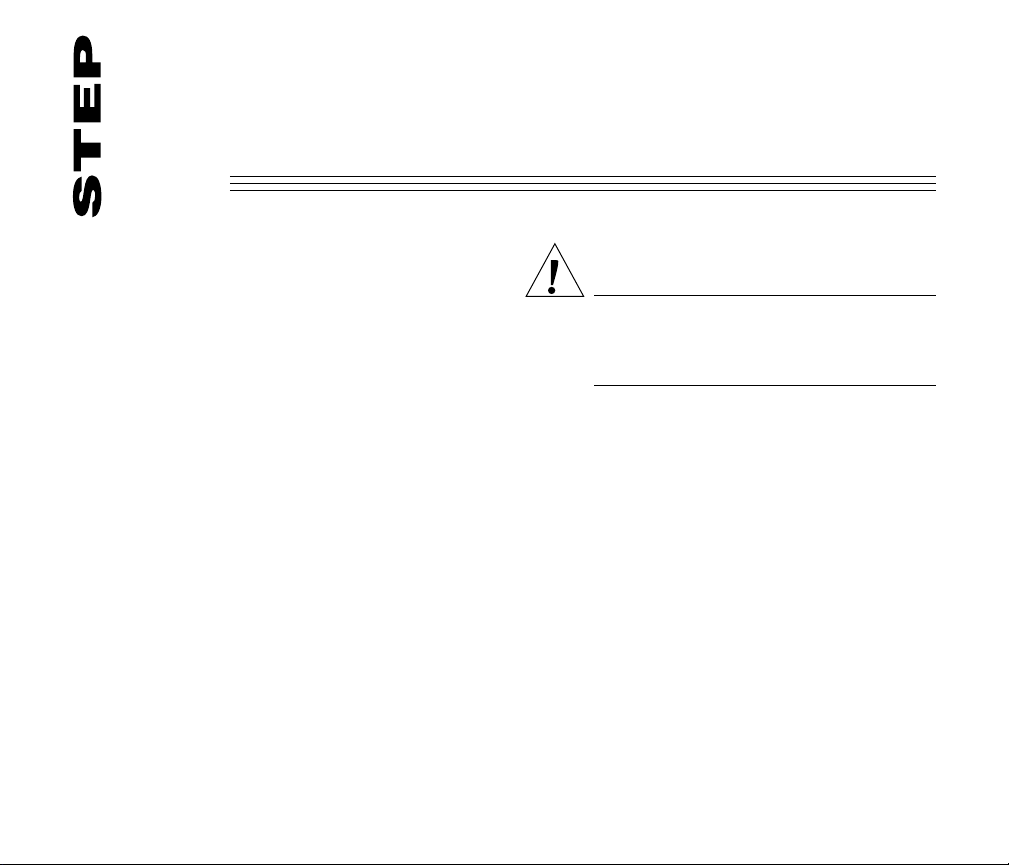
TOOLS REQUIRED FOR INSTALLATION
Assemble a flat blade screwdriver and other
tools as needed (right).
Test to make certain that your heating and
cooling systems are working properly. If either
does not work, contact your local heating/air conditioning dealer. To avoid compressor damage, do
not operate the cooling system if outdoor temperature is below 50° F [10° C].
TURN OFF POWER to the system at the heat
pump and at the fuse/circuit breaker panel.
Carefully unpack your new thermostat. Save
instructions, proof of purchase from packaging and original receipt.
FLAT BLADE
SCREWDRIVER
WIRE CUTTER/STRIPPER OR SHARP
KNIFE, IF NEEDED TO STRIP WIRES
SPIRIT LEVEL, IF NEEDED TO LEVEL
THERMOSTAT FOR APPEARANCE
HAND OR POWER
DRILL WITH 3/16 INCH
DRILL BIT, IF NEEDED TO
DRILL HOLES IN WALL
MASKING TAPE, IF NEEDED
TO LABEL WIRES AS THEY
ARE DISCONNECTED FROM
OLD THERMOSTAT
M849
4
Page 5
REMOVE OLD THERMOSTAT
2
WARNING
If your old thermostat is attached to a
junction box in the wall, it is likely that
120V are present. To prevent electrical
shock hazard,
fied electrician.
do not proceed
. Call a quali-
Disconnect wires from old thermostat or sub
base. Always label all wires as you disconnect
them from your old thermostat. Use the CT8611 Wire
Tags provided to label each wire with the appropriate
terminal designation as you remove it. It is important
to note the terminal designation when removing wires.
Not all thermostats are wired by color code.
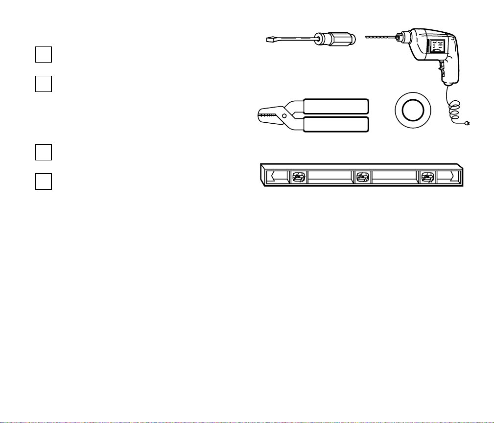
Keep the wires from falling back into the wall
by wrapping them around a pencil, as shown.
CAUTION
1. Disconnect power supply to prevent
electrical shock or equipment damage.
2. After wiring is complete, push excess
wire back into the hole, and plug hole
with nonhardening caulk, putty, or insulation to prevent drafts from affecting
thermostat operation.
Remove cover from old thermostat. If it doesn’t
snap off when pulled firmly from the bottom,
check for a screw that locks the cover.
Loosen screws holding thermostat to subbase,
wallplate or wall, and lift away.
WIRES THROUGH
WALL OPENING
M5136
5 69-0816
Page 6

Do not discard your old thermostat until you
have thoroughly checked out system operation with your new Honeywell CT8611 Heat Pump
Thermostat installed. If your old thermostat contains mercury, do not dispose of it in the trash, see
below.
RECYCLING THERMOSTAT
If this thermostat is replacing a
thermostat that contains mercury in
not
a sealed tube, do
place your old
thermostat in the trash. Contact your
local waste management authority
for instructions regarding recycling
and the proper disposal of your old
thermostat.
If you have questions, call Honeywell Inc. at
1-800-468-1502.
MERCURY
SWITCH
ANTICIPATOR
SCALE
COILED
BIMETAL
Typical location of a mercury switch
ANTICIPATOR
SETTING LEVER
in a thermostat.
M3376
6
Page 7

3
MOUNT THERMOSTAT SUBBASE
The subbase does not require leveling for
proper operation; level it for appearance only.
Thread wires through the center opening of
the subbase. Then, mount the subbase using
the two screws provided. Gently tighten the screws,
Remove thermostat from subbase (Fig. 1).
level the top surface of the subbase and then securely tighten the screws.
Mount the subbase directly onto the wall with
the screws included in the package. Use the
subbase as a template, and with a pencil, mark the
two mounting screw positions (Fig. 2). Use 3/16 in.
bit to drill holes for anchors. Gently tap anchors into
holes until they are flush with the wall surface.
. HT HEAT OFF COOL
Fig. 1—Removing thermostat from base. Fig. 2—Mounting subbase on wall.
F
A
N
O
N
A
U
T
O
A
U
X
.
H
E
A
T
M9073
WIRES THROUGH
WALL OPENING
WALL
ANCHORS
(2)
SUBBASE
7 69-0816
WALL
MOUNTING
SCREWS (2)
MOUNTING
HOLES
M5175
Page 8

WIRE THERMOSTAT TERMINALS
4
NOTE: All wiring must comply with local codes and
ordinances. If unsure about household wiring
procedures, call Honeywell Customer Assistance
with your questions Monday-Friday, 7:00 a.m.5:30 p.m., Central time, 1-800-468-1502.
Refer to the CT8611 Heat Pump Thermostat
Wiring Guide, form 69-0817, and to the wire
labels you applied when you removed the old
thermostat. Match the letter from your old thermostat wire with the appropriate letter on your
new thermostat. Follow any special instructions
provided in the Wiring Guide. Wire only those
terminals shown with lines connecting them.
Some terminals on the thermostat may not be
used.
RESTRICT
WIRING TO
THIS AREA
WIRING TO BE BELOW
THIS SURFACE
FOR STRAIGHT
INSERTION –
STRIP 5/16 in. [8 mm]
FRONT VIEW OF
TERMINAL AREA
FOR WRAPAROUND –
STRIP 7/16 in. [11 mm]
TOP SURFACE
OF SUBBASE
For each wire, loosen the terminal screw, slip
the wire beneath its matching terminal, and
tighten the screw.
The shape of the terminal barrier allows straight
or conventional wraparound wiring connections.
NOTE: Keep all wiring restricted to ribbed area
surrounding terminals (Fig. 3) to assure thermostat/subbase contact.
CROSS-SECTIONAL VIEW OF
TERMINAL AREA
Fig. 3—Keep wiring restricted to ribbed area
surrounding terminals.
8
M3062
Page 9

Figs. 4 and 5 illustrate typical hookups for the
CT8611 heat pump thermostat.
CT8611R
R
C
W1
L
Y1
P
E
DEFROST
CONTROL
1
POWER SUPPLY. PROVIDE DISCONNECT MEANS
AND OVERLOAD PROTECTION AS REQUIRED.
COMPRESSOR
CONTACTOR
MONITOR
EM. HT.
RELAY
W2
G
AUX. HT.
RELAY
O
B
FAN
C/O RELAY
HEAT
Fig. 4—Typical hook up of CT8611 with
jumper intact.
C/O RELAY
COOL
1
(HOT)
M9077
CT8611R
R
C
W1
L
Y1
P
E
MONITOR
DEFROST
CONTROL
L2
L1
1
POWER SUPPLY. PROVIDE DISCONNECT MEANS
AND OVERLOAD PROTECTION AS REQUIRED.
1ST STAGE
HEAT RELAY
1ST STAGE
COOL RELAY
W2
G
AUX. HT.
RELAY
EM. HT.
RELAY
O
B
C/O RELAY
HEAT
C/O RELAY
FAN
COOL
M9076
1
(HOT)
L2
L1
Fig. 5—Typical hook up of CT8611 with
jumper removed.
9 69-0816
Page 10

5
COMPLETE INSTALLATION
ADJUST CYCLE RATE
1st stage heating and 1st stage cooling cycle
rates are factory-set for heat pumps. The heat
pump compressor cycle rate cannot be adjusted.
To customize the thermostat’s performance to
different types of heating equipment, however, a
cycle rate adjustment screw is provided on the back
of the thermostat to control the auxiliary heat cycle
rate. Correct setting of the screw will provide optimum savings, See Fig. 6.
1A 1B
NOT USED
AUXILIARY HEAT
1B
CYCLE RATE
IN
OUT 1/2
M9075
Fig. 6—Cycle rate adjustment.
TURN
3 CPH
6 CPH
SLOWER
CYCLING
FASTER
CYCLING
NOTE: MOST APPLICATIONS DO NOT REQUIRE
A CHANGE IN CYCLE RATE.
The room air temperature normally varies
slightly from the comfort temperature setting with
the cycling of the heat pump or auxiliary heater.
INSTALL BATTERIES
Three AAA alkaline batteries are included with
the thermostat to prevent program loss in case of
power outage. Install batteries in back of thermostat as shown in Fig. 7. Without battery backup, the
BATTERY PLACEMENT
(NOTE CORRECT PLUS
AND MINUS DIRECTION)
10
M3058
Fig. 7—Battery placement.
Page 11

program will remain for only about 20 seconds in
the event of power loss.
When batteries are first installed, the display
will flash 1:00 PM and 32°. When the batteries are
low, the display will flash REPL BAT. You have 2030 seconds to replace batteries after removing them
from the thermostat. After 20-30 seconds, you will
have to reprogram. REPL BAT indication will disappear when the thermostat is mounted back onto the
powered subbase.
If batteries are completely dead, the display
will go blank when the thermostat is removed from
the subbase. After replacing the battery in this
case, reprogramming is necessary.
MOUNT THE THERMOSTAT
With system switch set to OFF, hang the thermostat on the tabs at the top of the subbase
(Fig. 8A). Swing down and press on lower edge
until thermostat snaps in place (Fig. 8B). Open
cover and tighten the captive mounting screws
(Fig. 8C).
A.
N
A
F
O
T
U
A
N
O
L
O
O
C
F
F
O
T
A
E
H
T
H
.
M
E
T
A
E
. H
X
U
A
T
A
E
. H
M
E
SYSTEMENRG. SAVE
M
C.
P
S
E
T
P
R
E
S
E
N
T
D
A
Y
/T
IM
E
H
O
L
D
T
E
M
P
H
E
P
ROOM
MON
HEAT ON
MORNIMG
T
E
M
P
E
R
A
T
U
R
E
P
R
E
S
E
N
R
U
N
R
O
G
R
A
M
P
E
R
D
A
Y
W
A
K
E
S
E
T
S
L
E
E
P
A
T
/C
O
O
L
T
S
E
T
T
IN
G
IO
D
T
IM
E
S
K
IP
L
E
A
V
R
E
T
U
R
N
E
X
E
N
T
A
H
E
A
D
W
A
R
M
E
R
P
E
R
IO
D
C
H
A
N
G
E
B
A
C
K
C
O
O
L
E
R
T
O
L
A
S
T
P
E
R
IO
D
B.
MORNIMG
SYSTEMENRG. SAVE
PM
ROOM
MON
HEAT ON
A
U
T
O
M9074
Fig. 8—Mounting the thermostat on subbase.
11 69-0816
Page 12
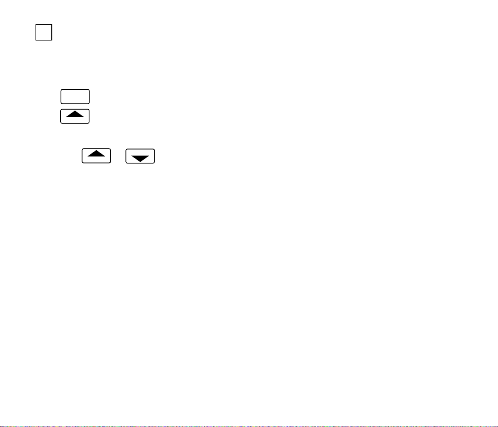
SET DAY AND TIME
Restore 24V power to the thermostat. When
power is applied, the display will read 1:00 PM and
indicate the room temperature. It will go off for a few
seconds, then begin to flash on and off. Set the
present day and time.
Press
Press
.
DAY/TIME
to set the current day. Each press of the
DAY
SET
PRESENT
DAY key advances the display one day.
BACK
Press TIME
AHEAD
or
to set the current time.
If the display will not come on:
— check the mounting of the thermostat to the
subbase. If loose or misaligned, remove thermostat and reinstall on the subbase, making sure it
is firmly attached.
— check to see that system power is on.
— check voltage between R and C; it should be 20
to 30 Vac.
12
Page 13
CHECK THERMOSTAT OPERATION
6
CAUTION
• Do not check the heating system operation by jumpering thermostat terminals at the primary control. This will
damage the thermostat.
• To avoid possible compressor damage,
do not operate the cooling system if the
outside temperature is below 50° F
[10° C]. See compressor manufacturer’s
instructions for further information.
• During cold weather, some heat pumps
will require that the crankcase heater
be energized several hours before operating the heat pump. Refer to the
manufacturer’s recommendations.
Restore the power to the system.
CHECK HEATING OPERATION
Move the system switch to HEAT and the fan
switch to AUTO. Press WARMER key until the setting is about 10° F [6° C] above room temperature.
Heating should start and the fan should run (there
may be a delay of 5-10 minutes before heat turns
on). Press COOLER key until the setting is about
10° F [6° C] below room temperature. The heating
equipment and fan should shut off.
During checkout, the backup heat will come
on immediately. During normal operation, the backup
heat will come on after a delay.
Backup (auxiliary) heat is more expensive to
operate than the heat pump and typically is used only
when the heat pump is unable to handle the load.
CHECK EMERGENCY HEATING
OPERATION
Move the system switch to EM. HEAT and the
fan switch to AUTO. Press WARMER key until the
setting is about 10° F [6° C] above room temperature. Heating should start and the fan should run.
CHECK COOLING OPERATION
Move the system switch to COOL and the fan
switch to AUTO. Press COOLER key until the setting is about 10° F [6° C] below room temperature.
Cooling should start and the fan should run. Press
WARMER key until the setting is about 10° F [6° C]
above room temperature. The cooling equipment
and fan should shut off.
13 69-0816
Page 14
ABOUT ADAPTIVE INTELLIGENT
RECOVERY
•
People perceive temperature
TM
from a variety of
sources, not only from the air in the room, but
also from their surroundings—walls, windows
and furnishings.
Human beings feel differences
•
in temperature
as slight as two degrees Fahrenheit.
Common household thermometers
•
thermostats
sense only air temperature, which
and standard
may or may not reflect how hot or cold the room
feels
actually
to a human being.
• This thermostat reads the temperature of the
wall as well as the air—and responds to temperature changes as little as one degree Fahrenheit—so room temperature is more likely to
“feel right.”
THE OPTIMUM COMFORT AND ENERGY
SAVINGS SOLUTION
This thermostat is actually a small but powerful
computer
. When calculating the exact time to turn
Recovery Begins
REPL
AM
BAT
PM
SUN MON TUE WED THU FRI SAT COOL ON HEAT ON
TEMPERATURE
System Operating
in Energy Savings Mode
AM
PM
SUN MON TUE WED THU FRI SAT COOL ON HEAT ON
WAKE LEAVE RETURN SLEEP TEMPORARY UNOCCUIPIED
WAKE LEAVE RETURN SLEEP TEMPORARY UNOCCUIPIED
REPL
SET
PT
BAT
on your furnace or air conditioner, it considers (1) air
temperature, (2) the temperature of the wall and (3)
when you want the comfort temperature established.
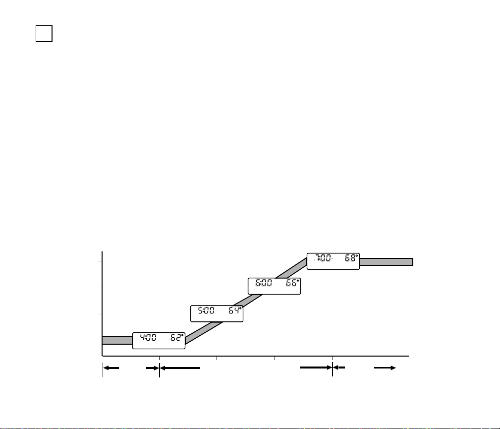
During Adaptive Intelligent Recovery
mostat increases the control temperature gradually
and turns the equipment on and off several times to
save energy by avoiding “overshooting” the comfort
temperature. See the current control temperature
anytime during recovery by pressing the PRESENT
SETTING key. On some models, both the SYSTEM
and ENERGY SAVING lights may be lit at the same
time during recovery.
This “smart” control learns from experience
day it checks how closely it “hit the target” and
adjusts the recovery start time accordingly.
It typically takes four to eight days after installation for this thermostat to adjust to the weather, life
style, home construction and heating/cooling system. The thermostat calculates the LEAVE/RETURN
recovery separately from the SLEEP/WAKE recovery.
System Operating
in Comfort Mode
REPL
AM
SET
PT
BAT
PM
SUN MON TUE WED THU FRI SAT COOL ON HEAT ON
WAKE LEAVE RETURN SLEEP TEMPORARY UNOCCUIPIED
REPL
AM
SET
PT
BAT
PM
SUN MON TUE WED THU FRI SAT COOL ON HEAT ON
WAKE LEAVE RETURN SLEEP TEMPORARY UNOCCUIPIED
Recovery Continues
SET
PT
TM the ther-
. Each
ENERGY
SAVINGS
PERIOD
THE THERMOSTAT USES THE SAME SCHEME TO RETURN GRADUALLY
TO LOWER COMFORT TEMPERATURE DURING THE COOLING SEASON.
RECOVERY FROM ENERGY SAVINGS
TIME
14
COMFORT
PERIOD
M171
Page 15

IF ADDITIONAL ASSISTANCE IS NEEDED, PLEASE CONTACT HONEYWELL CUSTOMER ASSISTANCE AT 1-800-468-1502, MONDAY-FRIDAY, 7:00 AM-5:30 PM, CENTRAL TIME. BEFORE YOU
CALL, PLEASE HAVE THE FOLLOWING INFORMATION AVAILABLE: TYPE OF HEATING SYSTEM,
IGNITION TYPE, WHETHER GAS OR ELECTRIC AIR CONDITIONING, MODEL NUMBER OF OLD
THERMOSTAT, NUMBER OF WIRES, AND TERMINAL DESIGNATIONS USED.
15 69-0816
Page 16

Home and Building Control Home and Building Control
Honeywell Inc. Honeywell Limited—Honeywell Limitée
1985 Douglas Drive North 740 Ellesmere Road
Golden Valley, Minnesota 55422 Scarborough, Ontario
M1P 2V9
Helping You Control Your World
G.S. 12-93 ©Honeywell Inc. 1993 Printed in Tiawan Form Number 69-0816
16
 Loading...