

Page 1
Honeywell
CT8611
Heat Pump
Thermostat Wiring Guide
Home and Building Control
Ploneywell Inc.
1985 Douglas Drive North
Golden Valley, Minnesota 55422
J. H. ■ Prinred in Tiuwnn * Furm NiiTflbcr 69-OE17 • [
Hone^ell
Helping You CotHrol Your World
Page 2

HOWTO USE THIS GUIDE
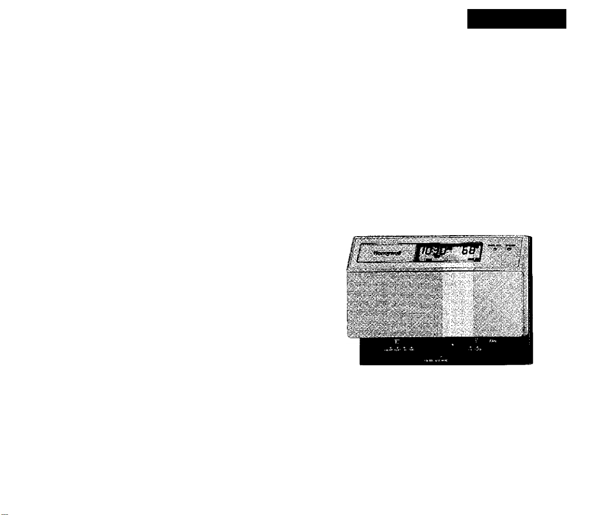
Before you disconnect the wires and remove your existing
thermostat, make certain this new thermostat, see Figs. 1
and 2, will replace it and that you understand how you will
reconnect the wiring. To do that, proceed as follows:
Step 1
Find the manufacturer of your heat pump in the Table of
Contents, and turn to the appropriate page.
Step 2
Expose the wiring on your current thermostat {the subbase)
and check that the terminals on your existing thermostat
coincide with the teminals shown in the second column
(Existing thermostat wiring).
if they do, read and follow the installation instructions provided
with the thermostat.
If they do not, call Honeywell Customer Assistance toll free at
1-800-468-1502, Monday-Friday, 7:00 a.m. - 5:30 p.m. Central
time, to make certain you can safely use this thermostat to
control your heat pump.
Before you call, please have the following information
available — thermostat model number and date code, heat
pump model number and manufacturer, and number of wires
connected to the thermostat. The date code is usually stamprid
on the back of the thermostat and is a four-digit number, e.g.,
9346.
NOTICE: ! his equipment is a Class B digital apparatus,
which complies with Canadian Radio Interference
Regulations, CRC c. 1374.
Page 3

TABLE OF CONTENTS
How to Use This Guide..................................................................... 3
Heat Pumps are Different................................................................ 6
Heat Pumps are Two Systems in One............................................ 7
Definitions of Terminal Functions.................................................8,9
Heat Pump Manufacturers.........................................................12-23
Amana........................................................................................12
American Standard .
Arcoaire................................................................................... 14
Bard...........................................................................................13
Borg Warner
B.D.P. (Bryant-Day/Night-Payne)............................................15
Carrier....................................................................................... 16
Comfortmaker...........................................................................14
Friedrich.................................................................................. 17
Heil Quaker
Janitrol..................................................................................... 13
Lennox...................................................................................... 19
Luxaire (Moncrief, Fraser, Johnston)......................
Rheem...
Ruud....................................................................................... 20
Snyder General.........................................................................14
Tappan.................................................................................... 13
Tempstar
Trane
Whirlpool
..........................................................................
................................................................................
.........
..................
.........
Williamson...
York..............................................................................................22,23
...........
..................................................
........................................................................
..............
..................................................................18
...................................
.......................................................................IS
.................!...............................................
.............................21
21
22,23
18
22
...20
13
Page 4
HEAT PUMPS ARE DIFFERENT
HEAT PUMPS ARE TWO SYSTEMS IN ONE
• Heat pun>p systems usually
have a supplemental,
“second stage" heating
system that operates only
when necessary. This heat
pump thermostat is designed
to minimize more expensive
second-stage operation,
indicated by the green AUX
light on your switching
subbase.
• With this thermostat, you will notice that your compressor
operates continuously during the recovery period. This may
appear to waste energy, but actually is more efficient.
Multiple ON-OFF cycles are neither necessary to achieve
comfort, nor are they as efficient for heat pump systems. By
reducing the number of cycles, you reduce the strain on
your system and extend equipment life.
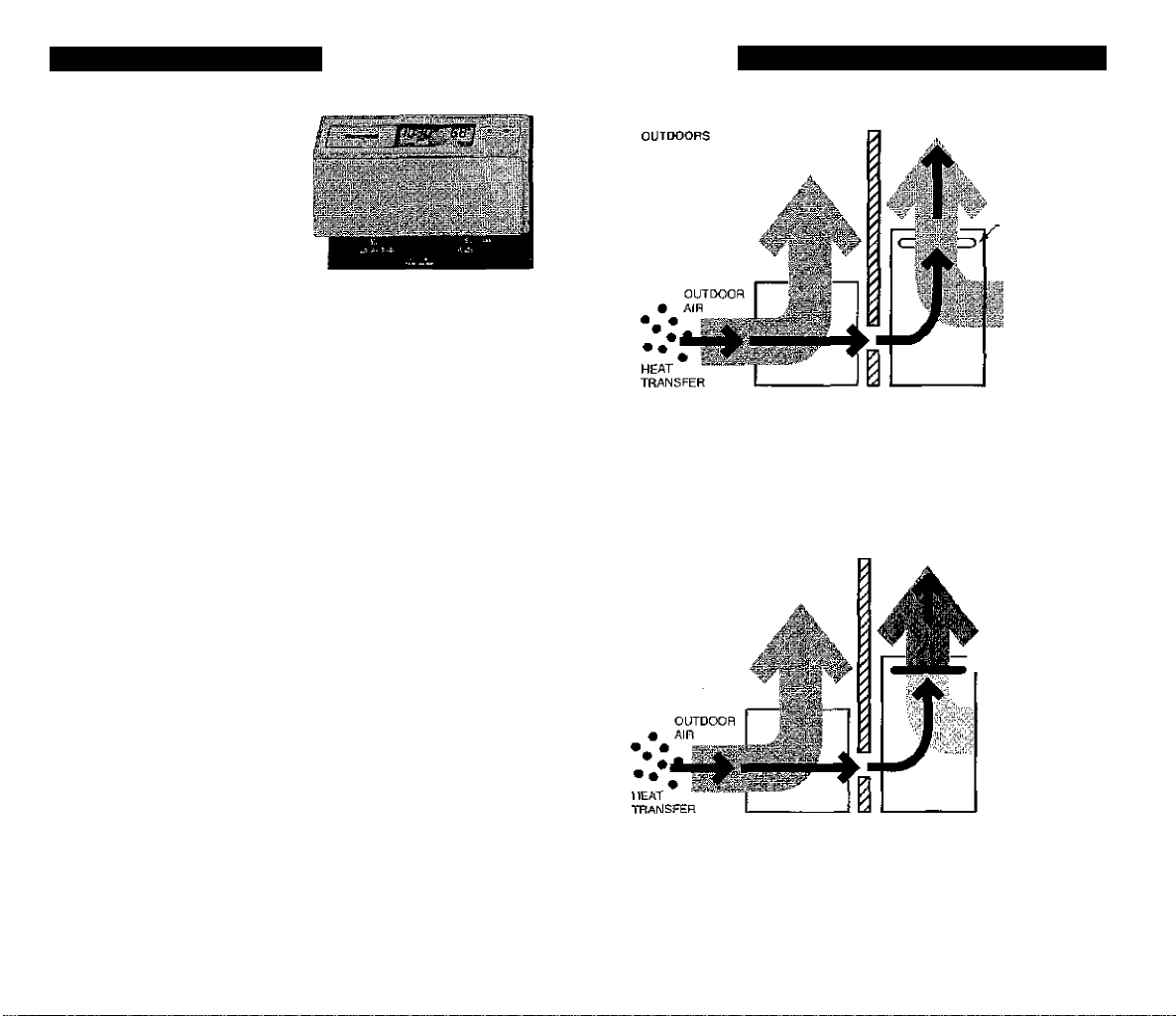
MILD WEATHER
INDOORS
■ AUXILIARY
HEATING
ELEMENT
OFF
INDOOR
AIR
In mild westher, virtuafiy all of the demand for heat in buildings
can be met by the heat pump compressor. This "First Stage"
process o\ moving heat indoors is very economical. As the
air becomes colder outside, the first stage may be unabfe to
deliver enough heat to maintain the desired comfort /evef
m the buiiding.
SEVERE WEATHER
OLrnKWRS
INDOORS
AUXILIARY
> HEATING
EUCMCNT
ON
i INDOOR
t AIR
During high heat demand, the thermostat wiU call for additiorm!
“Second Stage"power from the auxiliary heat system. This
auxiliary tieat is commonty electric “resistance" heat and is two
to three times more expensive to operate than the compressor.
If you have specific questions concerning the the operation of
your heat pump, please contact the equipment manufacturer.
Page 5

DEFINITIONS OF TERMINAL FUNCTIONS
Each terminal of the CT8611 controls a different heat pump
function. Here is a listing of the possible heat pump functions;
Function
STAGE HEAT:
Definition
When this terminal is activated, the
heat pump is on and providing heating
to the living space.
AUXILIARY HEAT:
When this terminal is activiatsd, the
auxiliary heating source is on because
the heat pump is unable to meet the
heating demand of the living space.
STAGE COOL;
When this terminal is activated, the
heat pump is on and providing
cooling to the iiving space.
COMPRESSOR;
When this terminal is activated, the
heat pump is on and providing either
heating or cooling to the living space,
depending on Ifie system switch
position.
C/0 VALVE HEAT:
Heating Changeover Valve. This
terminal is activated when the
system switch is in the HEAT position.
It provides changeover in heat pumps
that changeover in heating.
C/O VALVE COOL:
Cooling Changeover Valve. TTiis
terminal is activated when the
system switch is in the COOL position.
It provides changeover in heat pumps
tfiat changeover in cooling.
EM. HEAT:
Emergency Heat. This terminal is
activated when the system switch is
in the EM. HT position, in this situation,
the heat pump will not be activated.
FAN:
MULTIPLE
AUX. HEAT
LOADS:
OUTDOOR SENSOR:
OUTDOOR STAT:
POWER;
COMMON:
SYSTEM MONITOR:
When this terminal is activated, the
fan is on. With the fan switch in the
AUTO position, the tan cycles on and
off with the heat pump, VVith the fan
switch in the ON position, the fan is
on continuousty.
This terminal is activated when
additional auxiliary heat loads are
required. Since the CT86 M only has
provisions for one auxiliary heat load,
these loads must be connected to the
AUXILfARY HEAT terminal.
This terminal is not connected to the
CT8611. On your original thermostat,
this terminal was activated by an
outdoor sensor that controlled the
auxiliary heat source.
Outdoor Thermostat. This terminal is
activated when the system switch is in
the EM, HT. position. The outdoor
thermostat controls the amount of
auxiliary heat that will be activated.
This terminal connects to the power
side of the 24-volt transformer
This terminal connects to the common
side ot the 24-volt transformer.
Some heat pumps have the ability to
indicate when the heat pump is
malfunctioning. When this occurs, this
terminal is activated and the CHECK
LED is activated.
Page 6

AND OVERLOAD PROTECTION AS REQUIRED.
1\ POWER SUPPLY. PROVIDE DISCONNECT MEANS
A
AND OVERLOAD PROTECTION AS REQUIRED.
(HOT)
Fig. 1—Typical hookup of CT8611 with jumper intact.
10
Fig, 2—Typical hookup of CT8611 with jumper removed.
11
Page 7

BARD/JANlTROUTAPPAN/WILUAil/ISON
Notes
Q Jumper these two terminals if both are present.
This terminal must be connected to transformer common.
F lemove this factory-in stalled jumper for independent stage
1 heat and cool connection.
12
I '
Notes
[I This terminal musl be connected to transformer common.
B Leave factory-installed jumper in place.
El Connect muitiple second stage heating loads
to W2 terminals.
13
Page 8

ARCOAIRE/SNYDERGENERAUCOiFORTMAKER
B.D.P. (BRYANT-DAY/NIGHT-PAYNE)
Wiring
terminal
function
COMMON
POWER
COMPRESSOR
1ST STG.
HEAT
AUX. HEAT
FAN
C/O VALVE
HEAT
C/O VALVE
COOL
SYSTEM
MONITOR
EM. HEAT
MULTIPLE AUX.
HEAT LOADS El
Existing
thermostat
wiring
®—
©”©-
----
New
thermostat
wiring
®
-© .
®> /
Notes
O This terminal must be connected to transformer common.
0 Leave factoryanstalled jumper in place.
14
DEFROST
Notes
■®
□ This terminal must be connected to transformer common.
m Leave factory-installed jumper in place.
S Connect multiple second stage heating loads to
W2 terminals.
15
Page 9

CARRIER
FRIEDRICH
D This terminal must be connected to transformer common.
B Leave factoiY-instalted jumper in place.
16
Notes
D This terminal must be connected to transformer common.
n Leave factory-in stalled jumper in place.
B Tape off the end of the wire. Jumper is not required on
this thermostat (CT8611).
17
Page 10

LENNOX
Notes
□ This terminal must be connected to transformer common.
O Leave factory-installed jumper in place.
18
Notes
n This terminal must be connected to transformer common.
B Leave factory-installed jumper in place.
19
Page 11

RHEEM/RUUD
TRANE/AMERICAN STANDARD
Notes
D This terminal must be connected to transformer common.
0 Leave factory-installed jumper in place.
Notes
□ This terminal must be connected to transformer common.
0 Leave factory-installed jumper in place.
0 Tape off end. CT8611 replaces outdoor reset with improved
zero droop performance.
20 21
Page 12

YORK/BORG WARNER/LUXAIRE (IHONCRIEF, FRASER, JOHNSTON)
YORK/BORG WARNER
Notes
il This terminal must be connected to transformer common.
B Connect multiple second stage heating loads
to W2 terminals.
B Leave factory-installed jumper in place.
El If present on original equipment
22
Notes
n This terminal must be connected to transformer common.
B Remove factory-installed jumper.
23
 Loading...