

Page 1
CT8602C
Professional Fuel Sa ver Thermostat
Application
This thermostat provides energy saving control for a
24 Vac gas, oil, or electric heating or heating/cooling
system with independently controlled fan. System switch
positions include HEAT-OFF-COOL: fan switch positions
include ON-AUTO.
Power is supplied for the device by three AA alkaline
batteries (included in package). This allows the thermostat
to be compatible with all control applications.
Heat and cool anticipation is fixed; no adjustment is
necessary. Cycle rates are adjustable for heating.
The current rating is 1.6A maximum up to 30 Vac.
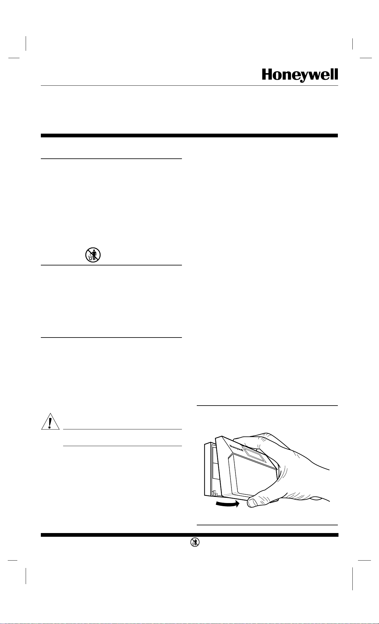
Recycling Notice
M3375
If this control is replacing a control that contains mercury in a sealed tube, do not place your old control in the
trash. Contact your local waste management authority for
instructions regarding recycling and the proper disposal of
your old control.
If you have any questions, call Honeywell Inc. at 1-800468-1502.
Installation
WHEN INSTALLING THIS PRODUCT…
1. Read these instructions carefully. Failure to follow
them could damage the product or cause a hazardous
condition.
2. Check the ratings given on the product to make sure
the product is suitable for your application.
3. After installation is complete, check out product
operation as provided in these instructions.
4. Allow thermostat to warm to room temperature
before operating.
CA UTION
Disconnect power supply to prevent electrical
shock or equipment damage.
Do not install the thermostat where it may be affected by:
— drafts or dead spots behind doors, in corners, or under
cabinets.
— hot or cold air from ducts.
— radiant heat from sun or appliances.
— concealed pipes and chimneys.
— unheated (uncooled) areas such as an outside wall,
behind the thermostat.
IF REPLACING AN EXISTING THERMOSTAT
Turn off power to thermostat at furnace or boiler. A two-
transformer system may require turning off two switches or
disconnects. Remove any existing wallplate or subbase
from wall. To avoid miswiring later, label or write down
each wire with the letter or number on the wiring terminal
as the wire is removed.
IF NEW INSTALLATION
Run cable to the hole in the selected wall location, and
pull about 3 in. (76 mm) of wire through the opening.
Color-coded, 18 gauge thermostat cable with at least one
conductor for each wiring terminal is recommended.
MOUNTING WALLPLATE
Remove thermostat from wallplate (Fig. 1).
The wallplate does not require leveling for operation,
but only for appearance. The wallplate mounts directly
onto the wall with the screws included in the package. Use
the wallplate as a template, and with a pencil, mark two
mounting screw positions that best fit the application using
two of the three mounting holes in the wallplate (Fig. 2).
Use 3/16 in. bit to drill holes for anchors. Gently tap
anchors into holes until flush with the wall surface. Thread
wires through the center opening of the wallplate. Then
mount the wallplate using the two screws provided. Gently
tighten screws, level top surface of wallplate, and securely
tighten the screws.
Fig. 1—Removing thermostat from wallplate.
IMPORTANT: Push excess wire back into the hole, and
plug the hole with non hardening caulk, putty or
insulation to prevent drafts from affecting thermostat operation.
LOCATION
Install thermostat and wallplate about 5 ft. (1.5m)
above the floor in an area with good air circulation at
room temperature.
S. M. • Rev. 3-95 • • ©Honeywell Inc. 1995 • Form Number 69-0446—2
M8850
1 69-0446—2
M3375
Page 2
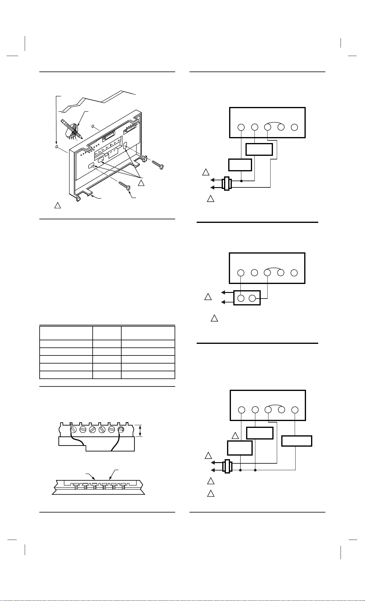
Fig. 2—Mounting wallplate on wall. Fig. 4—CT8602C heating-only circuit in a
continuous pilot gas system.
WALL
ANCHORS
(2)
WIRES THROUGH
WALL OPENING
USE TWO MOUNTING HOLES THAT
1
BEST FIT APPLICATION.
WALL
WALLPLATE
MOUNTING
HOLES (3)
1
MOUNTING
SCREWS (2)
M2917
WALLPLATE
FACTORYINSTALLED
JUMPER
G
W
FAN RELAY
GAS
1
L2
L1
(HOT)
1
VALVE
24V
POWER SUPPLY. PROVIDE DISCONNECT MEANS
AND OVERLOAD PROTECTION AS REQUIRED.
RCR
Y
M121A
WIRING
All wiring must comply with local electrical codes and
ordinances.
Disconnect power before wiring to prevent electrical
shock or equipment damage.
The shape of the terminal barrier permits insertion of
straight or conventional wraparound wiring connections.
Either method is acceptable.
Refer to Table 1 and Fig. 4 through 8 for wiring guidelines.
NOTE: Keep all wiring restricted to ribbed area surrounding
terminals (Fig. 3) to assure thermostat/wallplate contact.
TABLE 1—TERMINAL CROSS REFERENCE.
Old Thermostat
Terminal Marked Function
G or F Fan G
Y or C Cooling Y
W or H Heating W
RC, V, VC or R Power RC
RH, M, VR, 4 Power R
Fig. 3—Keep wiring restricted to ribbed area
surrounding terminals.
FOR STRAIGHT
INSERTION –
STRIP 5/16 in. [8 mm]
FRONT VIEW OF
TERMINAL AREA
WIRING TO BE BELOW
THIS SURFACE
CROSS-SECTIONAL VIEW OF
TERMINAL AREA
New Thermostat
Terminal Marked
FOR WRAPAROUND –
STRIP 7/16 in. [11 mm]
RESTRICT
WIRING TO
THIS AREA
TOP SURFACE
OF SUBBASE
M2927
Fig. 5—CT8602C heating-only circuit in an oil
system.
WALLPLATE
FACTORYINSTALLED
JUMPER
G
W
L1
HOT
)
(
1
L2
POWER SUPPLY. PROVIDE DISCONNECT MEANS
1
AND OVERLOAD PROTECTION AS REQUIRED.
TT
OIL PRIMARY
RCR
Y
M122
Fig. 6—CT8602C heating/cooling circuit in a
single transformer system with gas heat and
electric cooling or electric heat and electric
cooling, RC and R terminals.
WALLPLATE
FACTORYINSTALLED
JUMPER
G
W
FAN RELAY
2
HEATING
PRIMARY
CONTROL
24V
POWER SUPPLY. PROVIDE DISCONNECT MEANS
AND OVERLOAD PROTECTION AS REQUIRED.
PRIMARY CONTROL SUCH AS GAS VALVE OR
ELECTRONIC IGNITION MODULE.
L1
HOT
(
L2
1
)
1
2
RCR
COOLING
CONTACTOR
Y
M119
69-0446—2 2
Page 3

Fig. 7—CT8602C heating/cooling circuit in a two
transformer (one for heating, one for cooling)
system with gas heat and electric cooling, RC
and R terminals. Remove factory-installed R-RC
jumper.
WALLPLATE
Setting and Adjustments
ADJUSTING CYCLE RATE
NOTE: MOST APPLICATIONS DO NOT REQUIRE A
CHANGE IN CYCLE RATE.
1
L1
(HOT)
L2
1
G
W
24V
L1
HOT
)
(
L2
1
POWER SUPPLY. PROVIDE DISCONNECT MEANS
AND OVERLOAD PROTECTION AS REQUIRED.
PRIMARY CONTROL SUCH AS GAS VALVE OR
2
ELECTRONIC IGNITION MODULE.
2
HEATING
PRIMARY
CONTROL
24V
FAN RELAY
RCR
COOLING
CONTACTOR
Y
M118
Fig. 8—CT8602C heating/cooling circuit in an oil
heating and electric cooling system. Heating
transformer is in oil primary, RC and R terminals. Remove factory-installed R-RC jumper.
WALLPLATE
RCR
COOLING
CONTACTOR
Y
L2
L1
HOT
(
G
W
1
)
TT
OIL PRIMARY
FAN RELAY
The room air temperature varies slightly from the comfort temperature setting with the cycling of the furnace or
air conditioner. The equipment cycles off and on as the
room temperature approaches the setpoint.
The cycle rate of this thermostat is set for heating at six
cycles per hour and for cooling at three cycles per hour as
shipped from the factory. The cooling cycle rate cannot be
adjusted. The heating cycle rate can be adjusted by turning
one or both cycle rate adjustment screws located on the
back of the thermostat. See Fig. 9. Back out the screw about
one-half to one turn, or turn in until tight.
ADAPTIVE INTELLIGENT RECOVERY™/
CONVENTIONAL RECOVERY
The thermostat is factory-set for Adaptive Intelligent
Recovery™, but can be converted to conventional recovery
using screw 3A on the back of the thermostat as indicated in
Fig. 9.
With Adaptive Intelligent Recovery™, the room reaches
the comfort temperature at the exact time programmed into
the thermostat. The control temperature increases gradually, and turns the equipment on and off several times to
reach the comfort temperature slowly and on time. There is
no wasted energy associated with rapid temperature changes
and temperature overshoot.
With conventional recovery, program the start time to
be earlier than the desired comfort time. It may require
some trial and error to arrive at the best starting time.
L1
1
HOT
)
(
L2
1
24V
POWER SUPPLY. PROVIDE DISCONNECT MEANS
AND OVERLOAD PROTECTION AS REQUIRED.
Fig. 9—Adjustments.
RECOVERY
SELECTION
ADAPTIVE
INTELLIGENT ™
CONVENTIONAL
SYSTEM
GRAVITY
AIR/WATER
HOT
WATER
GAS/OIL
WARM AIR
ELECTRIC
WARM AIR
OUT 1/2
TO 1 TURN
(FACTORY SETTING)
OUT 1/2
TO 1 TURN
1A
TO 1 TURN
IN
OUT 1/2
TO 1 TURN
IN IN
1B
OUT 1/2
IN
3A
IN
(FACTORY SETTING)
OUT 1/2 TO 1 TURN
3A1A1B
2A 2B
TIME/TEMP
DISPLAY
24 HR IN
12 HR
o
C
o
F
2A 2B
OUT 1/2
TO 1 TURN
M120
IN
OUT 1/2
TO 1 TURN
M8857
NOTE: If you adjust screw 3A for conventional recovery, an
indicator appears in the lower right corner of the thermo-
stat display as a reminder that the Adaptive Intelligent
Recovery™ feature is not active. (Fig. 10).
Fig. 10—Conventional recovery indicator.
SET
PM
TUE
LEAVE
INDICATES
THERMOSTAT IS SET FOR
CONVENTIONAL RECOVERY
PT
M8878
SETTING TIME/TEMPERATURE
The display readout can be converted between a 12 and
24 hour clock or °C and °F using screws 2A and 2B as
indicated in Fig. 9.
INSTALLING BATTERIES
Power is supplied for the thermostat by three AA alkaline batteries. Batteries are included with thermostat. Install
batteries in back of thermostat as shown in Fig. 11. The
display will flash 1:00 PM and room temperature.
When the batteries are going dead, the display will flash
REPL BAT. Set system switch to OFF. Remove the thermostat from the wall and install three new AA alkaline
batteries. We recommend Energizer® batteries. Change
3 69-0446—2
Page 4

batteries within approximately 30 seconds from the time
SET
PRESENT
DAY/TIME
SET
PRESENT
DAY/TIME
DAY
the batteries are removed to prevent program loss and
reprogramming.
IMPORTANT: The low battery warning displays about
two months before the batteries are dead. When the
batteries are dead, the system shuts down. After batteries are replaced, thermostat requires reprogramming.
Fig. 11—Battery placement.
BATTERY
PLACEMENT
(NOTE CORRECT PLUS
M2083
AND MINUS DIRECTION)
MOUNTING THE THERMOSTAT
Hang the thermostat on the tabs at the top of the base
(Fig. 12a). Swing down and press on lower edge until
thermostat snaps into place (Fig. 12b). Open the cover, and
tighten the captive mounting screws (Fig. 12c).
SETTING DAY AND TIME
Set present day and time. When the thermostat is first
turned on, the display will read 1:00 PM and room temperature. It will go off for a few seconds, then begin to flash on
and off.
Press .
Press TIME or to set the current time.
AHEAD
BACK
Press .
Press to set the current day. Each press of the
DAY KEY advances the display one day.
If the display does not come on:
• Check mounting of thermostat to wallplate. If loose or
misaligned, remove thermostat and reinstall on
wallplate, making sure it is firmly attached.
• Check to see that all the batteries are good and installed correctly.
Fig. 12—Mounting thermostat on wallplate.
A.
C.
RUN
PROGRAM
SET
PRESENT
DAY
DAY/TIME
HOLD
SET
TEMP
HEAT/COOL
B.
PM
MON
RETURN
HEAT ON
PM
MON
HEAT ON
RETURN
TEMPERATURE
PRESENT
SETTING
WAKE
SLEEP
RETURN
AHEAD
BACK
TIME
LEAVE
WARMER
COOLER
PERIOD
CHANGE
TO LAST
PERIOD
SKIP
NEXT
M8849
69-0446—2 4
Page 5

Checkout
HEATING
Move the system switch to HEAT and the fan switch to
AUTO. Press WARMER key until the setting is about 10°F
(6°C) above room temperature. Heating should start and
the fan should run after a short delay. Press COOLER key
until the setting is about 10°F (6°C) below room temperature. The heating equipment should shut off.
COOLING
CA UTION
Do not operate cooling if outdoor temperature is
below 50°F (10°C). Refer to manufacturer’s recommendations.
NOTE: When cooling setting is changed, thermostat will
wait up to five minutes before turning on the air conditioner. This delay protects the compressor.
Move the system switch to COOL and the fan switch to
AUTO. Press COOLER key until the setting is about 10°F
(6°C) below room temperature. The cooling equipment and
fan should start. Press WARMER key until the setting is
about 10°F (6°C) above room temperature. The cooling
equipment and fan should stop.
FAN
Move the system switch to OFF, and the fan switch to
ON. The fan should run continuously. When the fan switch
is in the AUTO position, the fan cycles with the heating or
cooling system.
INSTALLER SELF-TEST (Optional)
Perform the following test as a check of all thermostat
functions. If thermostat does not respond as indicated,
replace thermostat.
1. Press AHEAD and BACK keys at the same time.
while holding down keys, all segments of the display should
be on (see Fig. 13).
Fig. 13—All segments on display.
REPL
AM
BAT
PM
SUN MON TUE WED THU FRI SAT COOL ON HEAT ON
WAKE LEAVE RETURN SLEEP TEMPORARY
2. Set system switch to OFF. Press AHEAD and BACK
and PRESENT SETTING keys at the same time to enter
self-test.
3. Press each key as listed on next page, and look for
response listed as key is held down and released.
SET
PT
M8856
5 69-0446—2
Page 6

System Press
RETURN
LEAVE
Switch
Position
OFF 03 Blank
This
Key
CHANGE
TO LAST
PERIOD
SKIP
NEXT
PERIOD
PRESENT
SETTING
Look For This Response
Key
Down
Key
Released
07 Blank
15 Blank
First
Digit
Cycle Rate Setting
(cph at 50% On Time)
0 or 1 1
2 or 3 3
4 or 5 9
6 or 7 6
COOL (with
fan in
PRESENT
SETTING
15 Cooling and fan
on.
AUTO)
PRESENT
SETTING
OFF 06 Blank
WARMER
COOLER
AHEAD
BACK
15 Colling and fan
off.
02 Blank
05 Blank
04 Blank
01 Blank
00 Blank
(CHECK
WAKE
12 See note A
EACH
POSITION)
OFF 08 Blank
SLEEP
DAY
13 Microprocessor
mask no. and
revision no.
SET
HEAT/COOL
SET
PRESENT
DAY/TIME
HEAT 14 Heating on.
1
▲▲
OFF 10 Blank
SET
PRESENT
DAY/TIME
SET
PRESENT
DAY/TIME
HOLD
TEMP
RUN
PROGRAM
09 Blank
14 Blank
14 Heating off.
11 Normal operating
display.
END SELF-TEST
1 For electric heat fan operation, the fan operates with
▲▲
the heating system when the fan switch is in AUTO.
A HEAT displayed when system switch is in HEAT,
COOL when in COOL, neither when in OFF. A fourdigit code is displayed with each digit explained as
follows.
Second
Digit
Clock
(hr) Degrees
Recovery
Setting
0 12 F Conventional
1 12 C Conventional
2 12 F Adaptive Intelligent
Recovery™
3 12 C Adaptive Intelligent
Recovery™
4 24 F Conventional
5 24 C Conventional
6 24 F Adaptive Intelligent
Recovery™
7 24 C Adaptive Intelligent
Recovery™
▼▼
▼▼
Third Digit System Switch Position
0 OFF
2 COOL
4 HEAT
Fourth Digit System Switch Position
0 Any position
1 HEAT, OFF, or COOL
4 Any position
5 HEAT, OFF, or COOL
Allow thermostat to reach room temperature before programming. Then refer to owner’s manual for programming
instructions and homeowner troubleshooting.
This equipment is a Class B digital apparatus which complies with Canadian Radio Interference Regulations, CRC c. 1374.
Home and Building Control Home and Building Control Helping You Control Your World
Honeywell Inc. Honeywell Limited—Honeywell Limitée
1985 Douglas Drive North 740 Ellesmere Road
Golden Valley, MN 55422 Scarborough, Ontario
M1P 2V9
69-0446—2 6
Printed in U.S.A.
QUALITY IS KEY
 Loading...