

Page 1
Thermometer Scale Range: 45
Installation Instructions
o
F to 85o F [7o C to 29o C].
Electrical Ratings: 24 to 27 Vac.
Do-It-Yourself Models
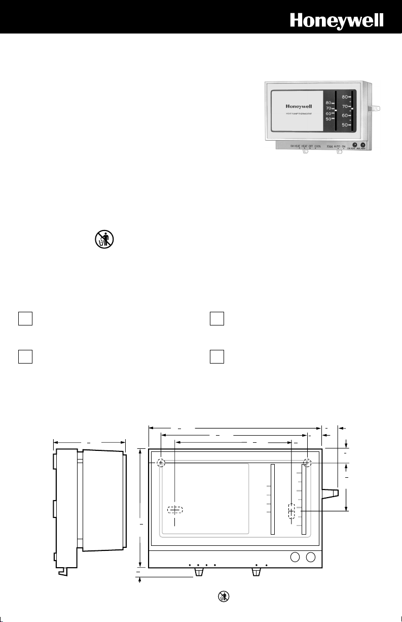
Your Honeywell Thermostat
Your new Honeywell CT70A Heat Pump Thermostat
provides low voltage (24 Vac) control of two-stage heating
and one-stage cooling in heat pump systems, using
manual changeover. Light-emitting diodes (LEDs) provide
emergency heat and auxiliary heat indication.
Recycling Notice
This control contains mercury in a sealed tube. Do not
place control in the trash at the end of its useful life.
M3375
1 PREPARATION
Your Honeywell thermostat should be properly
installed if you follow these instructions step-by-step.
It is recommended that as you read, understand and
complete each step, you check ✔ it off with pencil or pen.
Check thermostat suitability for your home’s system
by reviewing the ratings listed on the front of these
instructions and reviewing the CT70 Heat Pump Thermostat Wiring Guide enclosed.
CT70A
Heat Pump Thermostat
If this control is replacing a control that contains mercury in
a sealed tube, do not place your old control in the trash.
Contact your local waste management authority for
instructions regarding recycling and the proper disposal of
this control, or of an old control containing mercury in a
sealed tube.
If you have questions, call Honeywell Inc. at
1-800-468-1502.
Make certain that your home’s heat pump system is
working, especially if it has been inoperative for a
length of time. If the system does not work, contact your
local heating dealer for assistance.
Carefully unpack your new thermostat. Save
packages of screws, instructions, receipt and proofof-purchase.
2 THERMOSTAT MOUNTING DIMENSIONS
11
4 [119]
1
2 [52]
16
9
3
32
[83]
3
[5]
16
S.M. • 8-94 • Printed in U.S.A. • • ©Honeywell Inc. 1994 • Form Number 69-0846
16
EM. HEAT HEAT OFF COOL
31
3 [101]
32
1
[13]
2
3
[10]
80
70
60
8
11
[9]
32
3
8
[10]
9
1
32
[33]
9
3 [83]
32
80
70
60
50
50
AUTO ON
M3375
EM. HEAT AUX. HEAT
M7306
Page 2
3 REMOVE OLD THERMOSTAT
BACK OF DEVICE
WARNING
Begin by turning off power to the heat pump at the
main service panel.
Remove cover of old thermostat—cover normally
snaps off when pulled firmly from the bottom. If it
resists, check for a screw that locks the cover.
Before removing the old thermostat from the wall,
look at it carefully to locate the heat anticipator
adjustment mechanism. (See illustration to help you
recognize the heat anticipator.)
MERCURY
SWITCH
ANTICIPATOR
SCALE
Make a note here of that anticipator setting for
reference in setting the anticipator on your new thermostat.
The heat anticipator pointer, if adjustable, will be set at one
of a series of numbers representing the current rating for
the primary control of your heat pump. The number will be
one of the following: .2, .4, .8, etc., or 0.2, 0.4, 0.8, etc. If
no heat anticipator indication is showing, do not be
concerned for now; go on to the next step.
Loosen screws holding thermostat base to wall and
lift away.
Disconnect wires from old thermostat. As you
disconnect each wire, tape the end and label it with
the enclosed wiring labels to make reconnection to new
thermostat easier.
Check the old insulation for cracks, nicks or fraying,
and apply high quality plastic tape where necessary
for adequate insulation.
Retain the old thermostat for reference purposes
and until your new thermostat is functioning
smoothly.
ANTICIPATOR
SETTING LEVER
M8449
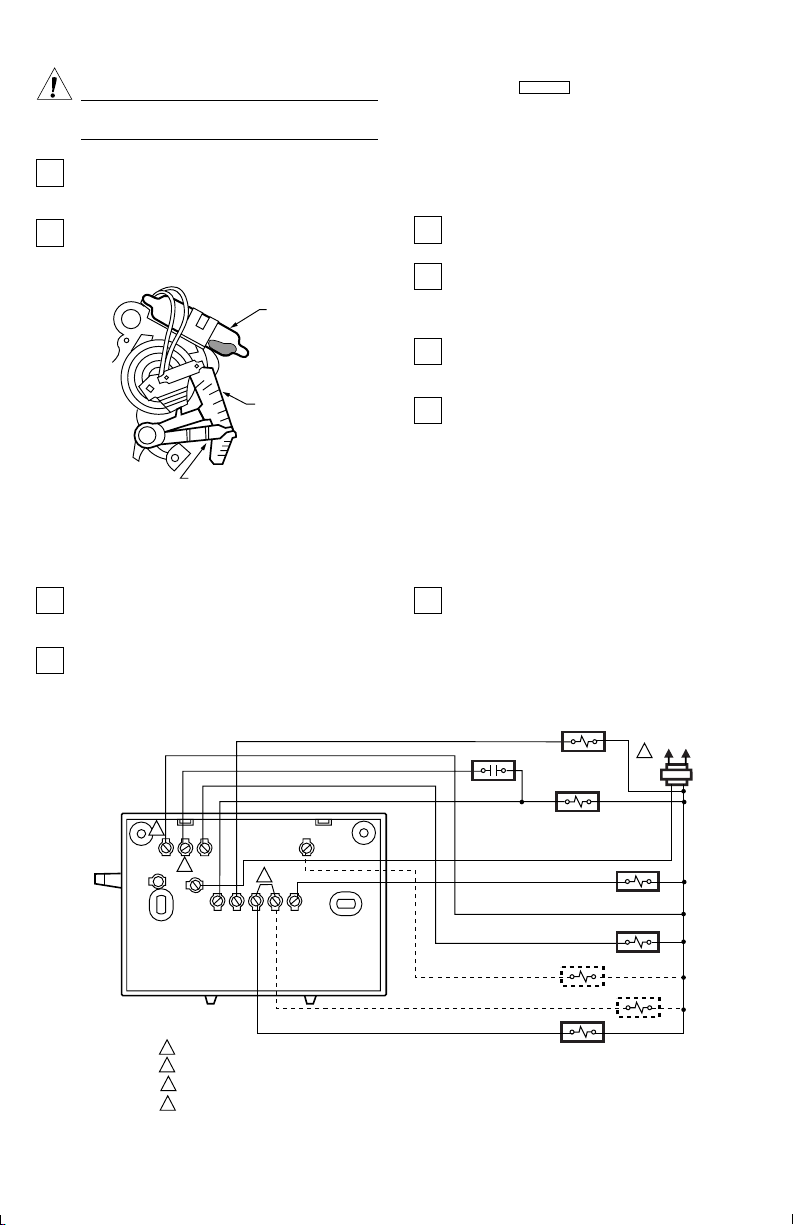
4 WIRE AND MOUNT NEW THERMOSTAT
This thermostat can be mounted directly to the wall
or on a horizontal outlet box. Choose the method
that best fits your installation.
Grasp the thermostat cover at the top and bottom
with one hand. Pull outward on bottom edge of the
cover until it snaps free of the thermostat base. Carefully
remove and save the packing material surrounding the
mercury switches.
4
X
LB
W2
3
R
POWER SUPPLY. PROVIDE DISCONNECT MEANS AND OVERLOAD PROTECTION AS REQUIRED.
1
REMOVE W1-Y1 JUMPER WHEN HEAT RELAY 1 IS USED.
2
WHEN L TERMINAL IS CONNECTED TO SYSTEM MONITOR, EM. HEAT. LED ALSO INDICATES COMPRESSOR MALFUNCTION.
3
X TERMINAL MUST BE CONNECTED FOR PROPER OPERATION.
4
2
OEG
Y1
W1
Run wiring (if necessary) to the location. If the
wiring is plastered into the wall, make a hole next to
the cable and loosen the wires so that they can be pushed
back into the wall later. Thread wires through the hole in
packing material saved above. Connect the wires to the
terminals on the back of the thermostat according to the
labels you placed on the wires or as shown in the wiring
diagram.
L1
(HOT)
L2
1
EM. HEAT
RELAY
AUX. HEAT
RELAY
HEAT RELAY 1
M8447
SYSTEM
MONITOR
CHANGEOVER
RELAY (COOL)
FAN RELAY
CHANGEOVER
RELAY (HEAT)
COMPRESSOR
CONTACTOR
69-0846 2
Page 3

Push the excess wire back through the hole and
plug any opening with packing material to prevent
drafts that may affect thermostat performance.
Loosely secure the thermostat to the wall or outlet
box with screws through the two mounting holes at
the middle of the device. The sheetmetal screws included
with the thermostat are designed for use in plaster walls
that do not need anchors.
5 CHECK OUT THERMOSTAT
Turn on the power to the heat pump system.
To check heating, move the system switch on the
thermostat to HEAT and the fan switch to AUTO.
Move the set point lever to about 10
temperature. Heating should start and the fan should run.
Move the set point lever about 10
temperature. Heating and fan should shut off.
NOTE: To prevent compressor short cycling, a minimum-
off timer may be included to prevent the compressor
from starting for up to five minutes from when the
thermostat last turned off the compressor, or from when
the system first received power.
o
F [6o C] above room
o
F [6o C] below room
6 SETTING THERMOSTAT
Move the set point lever to the desired control point
on the temperature scale.
Move the system switch and fan switch to the
desired operating positions.
The system switching positions control the system
operation as follows:
EM.HT.: Emergency heat relay is energized. Cooling
system is off. Compressor is de-energized. Fan runs on
call for heat if fan switch is in AUTO position. EM.HT.
LED is on continuously.
Exactly level the thermostat using a spirit level or
plumb line. An incorrectly leveled thermostat will
cause inaccurate temperature control. Tighten the two
mounting screws at the middle of the device. Install two
screws in top mounting holes and tighten.
Replace the thermostat cover.
Check cooling only if outdoor temperature is at least
o
50
F [10o C]. To check cooling, move the system
switch on the thermostat to COOL and the fan switch to
AUTO. Move the set point lever about 10
room temperature. Cooling and fan should start (see
NOTE above). Move the set point lever about 10
above room temperature. Cooling and fan should shut off.
To check fan, move the system switch to OFF, and
the fan switch to ON. The fan should run continuously. Move the fan switch to AUTO. In this position, the
fan operates in response to the thermostat in both heating
and cooling.
HEAT: Heat pump equipment is providing warm air to the
living space.
OFF: All heating/cooling equipment is de-energized.
COOL: Heat pump equipment is providing cool air to the
living space.
The fan switching positions control the fan operation as
follows:
AUTO: The fan operates in response to the thermostat in
both heating and cooling.
ON: The fan operates continuously.
o
F [6o C] below
o
F [6o C]
3 69-0846
Page 4

7 TROUBLESHOOTING
Your Honeywell thermostat requires little or no attention. Most problems can generally be traced to the following:
Symptom Problem Corrective Action
Compressor doesn't
provide warm air.
Compressor will not
stop delivering warm
air.
Thermostat setting
and thermometer
reading disagree.
Compressor doesn't
provide cool air.
Equipment has compressor
protection time delay.
System switch at OFF or COOL
position.
Blown fuse or tripped circuit
breaker.
Heat pump power switch is at
OFF.
Improper connections to
thermostat.
Defective thermostat. (Here's
how you know: Remove the
thermostat from the wall.
Disconnect wire from W1
terminal. Touch W1 wire to
terminal R. The thermostat is
defective if the compressor
starts.) Some systems have a
time delay, so allow five
minutes. See step 5.
Other. Contact a qualified service technician for assistance.
Turn temperature setting lever
all the way down.
Thermostat is not level. Recheck the thermostat position on the wall. Use level to
Thermostat affected by drafts or
radiant heat.
Equipment has compressor
protection time delay.
System switch is in OFF or
HEAT position.
Blown fuse or tripped circuit
breaker.
Compressor switch (located
outdoors) is at OFF.
Improper connections to
thermostat.
Defective thermostat. (Here's
how you know: Remove the
thermostat from the wall.
Disconnect wire from Y1
terminal. Touch Y1 wire to
terminal R. The thermostat is
defective if the compressor
starts. Some systems have a
time delay, so allow at least five
minutes.) See NOTE in step 5.
Other. Contact service technician for assistance.
Wait five minutes and check for heat.
Move switch to HEAT position.
Replace fuse or reset circuit breaker.
Switch to ON.
With power to furnace at OFF, tighten all mounting and
terminal screws. Repair frayed or broken wires.
Exchange the thermostat (see Warranty).
Heater should start to cool within minutes. If not, turn off
power at the main service panel, and contact qualified
service technician.
make sure it is level. See step 4.
Contact a qualified service technician to change the
location. The thermostat should be about 5 ft [1.5m] above
the floor and on an inside wall.
Wait five minutes and check for cool.
Move switch to COOL position.
Replace fuse or reset circuit breaker.
Move switch to ON position.
With power to heat pump OFF, tighten all mounting and
terminal screws. Repair broken wires.
Exchange the thermostat. See Warranty.
69-0846 4
Page 5

Honeywell warrants this product to be free from defects in the workmanship or materials, under normal use and service, for
a period of one (1) year from the date of purchase by the consumer. If, at any time during the warranty period, the product is
defective or malfunctions, Honeywell shall repair or replace it (at Honeywell’s option) within a reasonable period of time.
If the product is defective,
(i) return it, with a bill of sale or other dated proof of purchase, to the hardware or home center store from which you
purchased it, or
(ii) package it carefully, along with proof of purchase (including date of purchase) and a short description of the malfunction,
and mail it, postage prepaid, to the following address:
Honeywell Inc, RG Department in Canada: Honeywell Limited/Honeywell Limitée
1050 Berkshire Lane 740 Ellesmere Road
Plymouth, MN 55441-4437 Scarborough, Ontario M1P 2V9
This warranty does not cover removal or reinstallation costs. This warranty shall not apply if it is shown by Honeywell that
the defect or malfunction was caused by damage which occurred while the product was in the possession of a consumer.
Honeywell’s sole responsibility shall be to repair or replace the product within the terms stated above. HONEYWELL SHALL
NOT BE LIABLE FOR ANY LOSS OR DAMAGE OF ANY KIND, INCLUDING ANY INCIDENTAL OR CONSEQUENTIAL
DAMAGES RESULTING, DIRECTLY OR INDIRECTLY, FROM ANY BREACH OF ANY WARRANTY, EXPRESS OR
IMPLIED, OR ANY OTHER FAILURE OF THIS PRODUCT. Some states do not allow the exclusion of incidental or
consequential damages, so this limitation may not apply to you.
THIS WARRANTY IS THE ONLY EXPRESS WARRANTY HONEYWELL MAKES ON THIS PRODUCT. THE DURATION
OF ANY IMPLIED WARRANTIES, INCLUDING THE WARRANTIES OF MERCHANTABILITY AND FITNESS FOR A
PAR TICULAR PURPOSE, IS HEREBY LIMITED TO THE ONE YEAR DURATION OF THIS WARRANTY. Some states do
not allow limitations on how long an implied warranty lasts, so the above limitation may not apply to you.
This warranty gives you specific legal rights, and you may have other rights which vary from state to state.
If you have any questions concerning this warranty, please write our Customer Assistance Center, Honeywell Inc.,
P.O. Box 524, Minneapolis, MN 55440-0524 or call 1-800-468-1502, Monday-Friday, 7:00 a.m.-5:30 p.m. Central time. In
Canada write Retail Products ON15-02H, Honeywell Limited/Honeywell Limitée, 740 Ellesmere Road, Scarborough,
Ontario M1P 2V9.
Limited One-Year Warranty
5 69-0846
Page 6

 Loading...