

Page 1
Honeywell
Heating, Air Conditioning or
Heating/Air Conditioning
Thermostats
INSTALLATION INSTRUCTIONS
The CT50A is for most ^as and oil
heating-on(y systems.
The CT50C is lor most electric
air conditio/irng-only systems.
The CT51A is lor most gas, oil, or electric
heating/electric air condillorring systems,
The CT53A is for milMvoltage heating systems,
DO'it-yourself models
CT50A,C; CT51A; CT53A
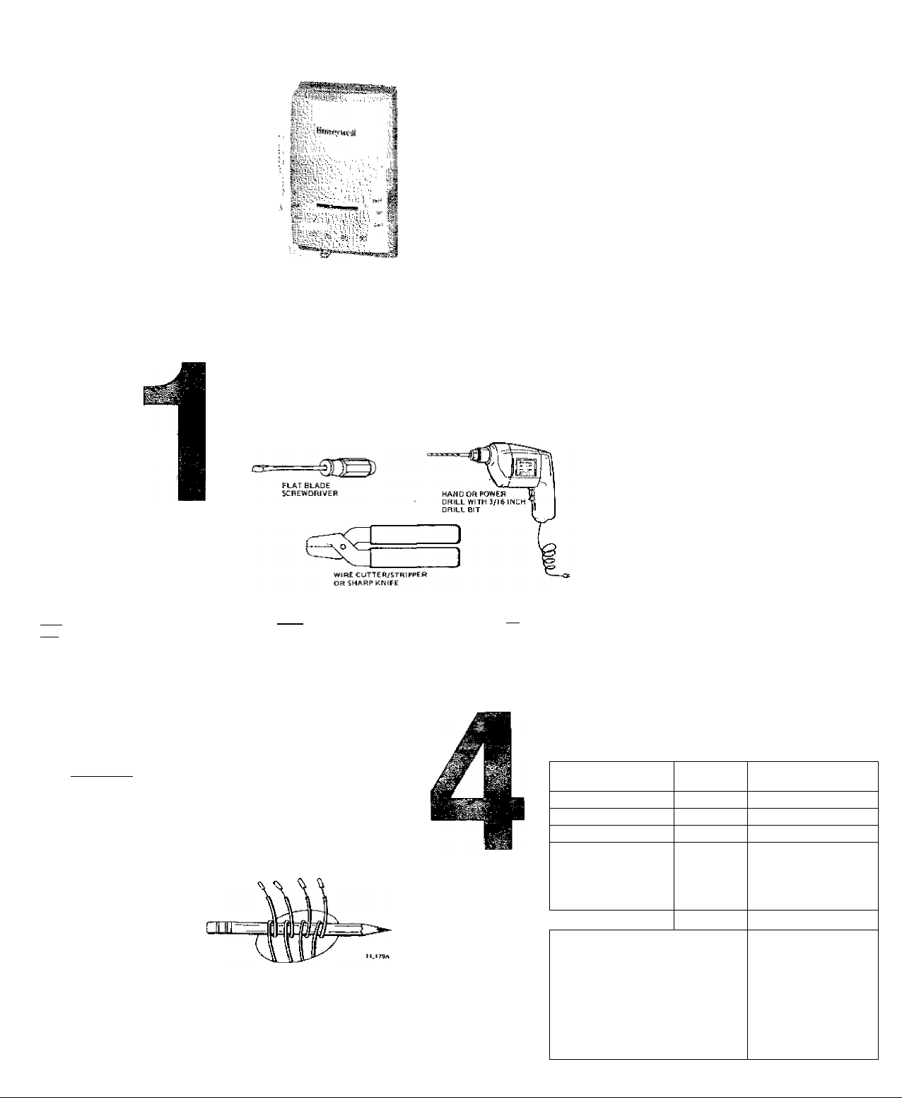
PREPARATION
Proper installation of your
new thermostat will occur
if you follow instructions STEP-
□
BY-STEP. tt is recommended
that as you read, understand and
complete each step, you check
I ^ I it off with pencil or pen.
CT51A shown
If you are unsure about wiring
procedures, please calf a
qualified service technician for
assistance.
X—
SPIPIT LEVEL OR PLUMB BOB AUO LINE
YOUR
NEW
THERMOSTAT
Your new Honeywell CT50A
Heating Thermostat will replace
most 15 to 30 V, 2-wire healing
system thermostats. The CT50A
is suitable only for gas or oil
heating systems (NOT lor air
conditioning, heating/air
conditioning, heat pump or
electric heating systems).
Your new CT50C Cooling
Thermostat will replace most 15
Chec)( thermostat
suitability for your home’s
system by reviewing YOUR NEW
□
THERMOSTAT section, above.
Ш
га
to 30 V, 3'Wire air conditioning
system thermostats (NOT for
heating, heating/air conditioning
or heat pomp systems}.
Your new CT51A
Heating/Cooling Thermostat will
replace most 15 tg 30 Y, 4-wire,
heating/cooling system
thermostats. The CT51A is
suitable for gas, oil or electric
heating/electric air conditioning
systems (NOT for heat pumps}.
Your new CT53A Heating
Thermostat is suitable for 250.
500 or 750 millivolt (mV) heating
systems only.
Assemble tools required,
ID
as shown left, r
Make certairt that your
burner/air conditioner
(where applicable) áre working,
□
especially if they hâve been
inoperative for any length of
time. If either does rot work,
contact your local heating/air
conditioning dealer. Do NOT
operate the air conditioning
system if outdoor temperature is
below 30® F [10° C],
Carefully unpack your
new thermostat. Remove
and discard the packing insert
□
under the cover.
Save package ol screws
□
and instruction pages.
CON
PREPAI
THERM
REMONi
WIRE A
CHECK
THERM
TROUB
RECALI
THER
, . FE
anticipator adjustment
mechanism, (See last
i illustration tinder step 4 to
'i help you recognize the heat
ahticipator.) Make a note
i here 1 [ of that
anticipator setting for future
reference. The heat
anticipator pointer, if
adjustable, will be set at one
ota series of numbers
representing the (electrical)
, current rating of the pritnary
! control of your system In
amps. The number will range
from 0,1ft to 1,0. If no heat
antidi pato r/ i n dr cat¡0 n (s
,i showing, do hot be
cortcerried; move on to the
next step.
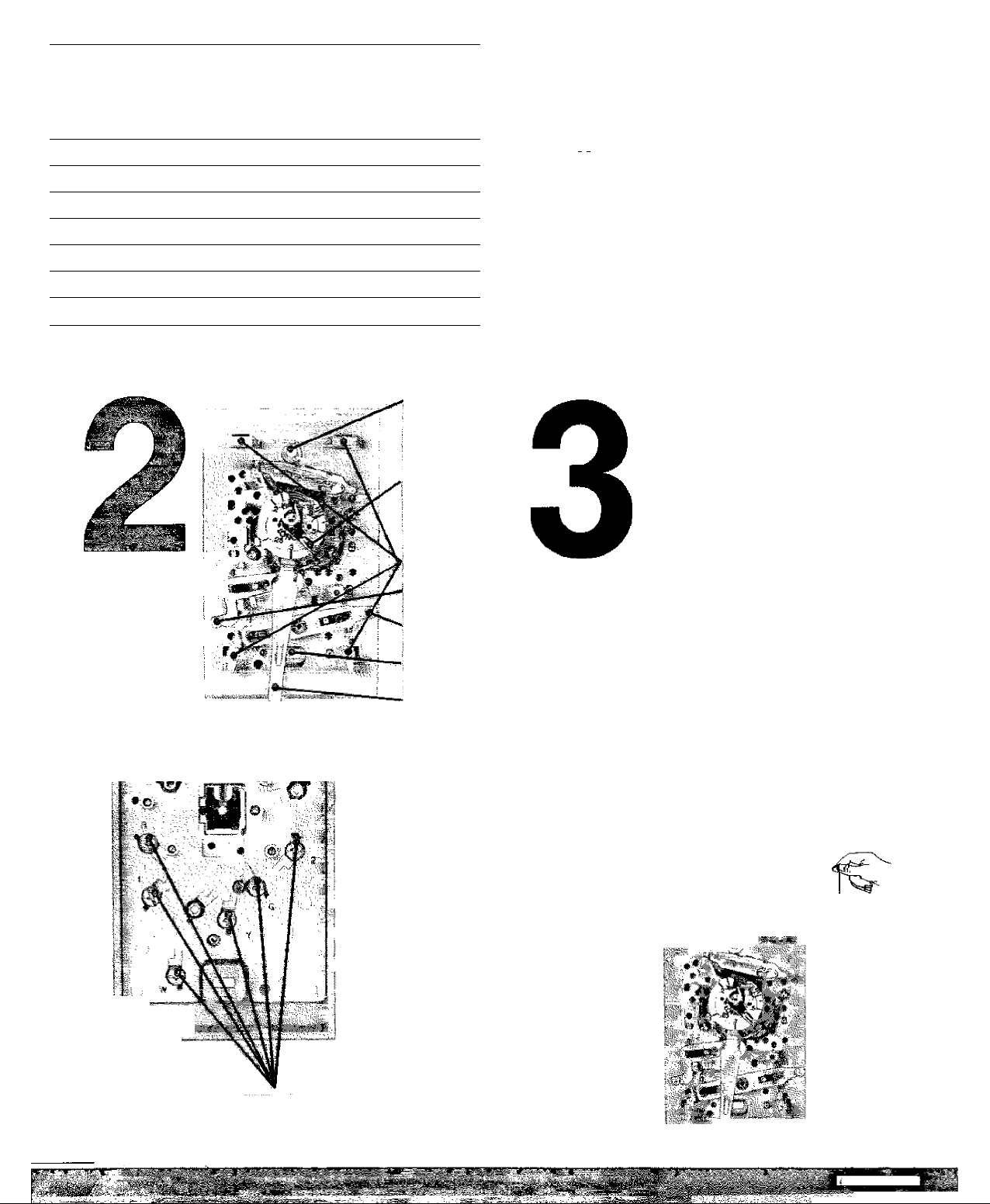
Loosen screws
I ■ holding thermostat
¡ báselo Buitoase qr wall, and
Lliftaway,
....
....
j.". ■
Disconnect wires
from old thermostat or
subbase. If your therrnostat
□
has more than 2 wires, as
you disconnect each wire,
tape the end and label it with
the letter of the terminal
designation to make
reconnection to new
thermostat easier. Take care
that these wires do not fall
back into the wall opening.
Keep the old
thermostat for
reference purposes until
□
i your new thermostat is
functioning smoothly.
WIRE AND
MOUNT
THERMOSTAT
For CT50A:
Connect each
wire from the wall to
□
either terminal on the
back of the thermostat.
Tighten the screws.
For CT60C or
CT51A:
Connect wires
□
from the wall to matching terminals on back of thermostat.
Tighten the screws,
NOTE: If terminal designations on old thermostat do not match
those on new thermostat, refer to chart below.
OLD THERMOSTAT
TERMINAL MARKED
e or F Fan
YorC
! Wor H Heati ng W
HC, V, VC or В
1 HH. M, VR, 4. A or R
i'flitriing CT51A for ELECTRIC furni
need to instali a jumper between t
and 2: If your old subbaSe ts a Q5v
: Q634G, you need the jumper. If in
I base number, see section 3. If jurr
i not installed, the furnace could 6v
; hazard. Use T ft gauge insulated
I installing, :
FUNCTION
Cooling Y
Power You have a 5-wire
:i, Power
NEW THERMOSTAT
TERMINAL MARKED
G
system, and cannot
use this thermostat;
we recommend a
CT87B instead.
R
ace systems, you may
herrrrostat termirials J;;
9G, Q539U,: Q634D or '
dbUbt аЬо1й cfld siib-
ipef is needed and is
érhéat; саиШд a firè::
fire; strip ends before.
Page 2
CONTENTS STEP
PREPARATION 1
THERMOSTAT FEATURES
REMOVING OLD THERMOSTAT
WIRE AND MOUNT NEW THERMOSTAT 4
CHECK OUT THE THERMOSTAT 5
THERMOSTAT SETTING
TROUBLESHOOTING
RECALIBRATE THERMOMETER 8
LIMITED oiii-VEAR WARfi^TY '
ly^^-iHaRfiywell iWMntbffie prediicttebt.free frcrndvlecl^m .
tom ttiB Oawol puvcbaw by Ih* mnaLmef-fl. SAanfUrine-duiliiS It4 wyrcnty.Ht-'.Vn*■ Чь’‘ДTpat^'WW;i
repair or «place 1Ца1Нопву»1в11>пй*а|Т1и|1Г|1Г1а1ввввГгаЫе|йв<1®<3 •ci'iirw.' . ' •••'.• ; •' . ' Д' •'.■ '
Л' Ц№ар1ы1ис1 isOetecIffe. : . ■‘■■■■ ■■■у.- ■ ■ .:■■■■.'■.■. -■ '■-■ •:•'
. a. irtLun it, wiha ЬЙсЛ iJiitoe pfMT^pWCltaSi, balhpdaAl« eriinh'Aijiei.jrm.'^fiich.jHbJ '•'.
b. pfectUQp H tafpftiiry.iietsi a м ort ван». rei»i)tqro»w'iiarwiEiri4f9<jitir»4rt, !iriJj'atwn to!S^i^'efMWri4iii^ '
F'latA.pasbfia praiïaitii. 1c»tl№ гсй1оч1П0в<Нгм4:
.HonayiwH.ftfc. ,. . ■ :
2
3
6
7
ITHa'vïFrsn^ PPW'TK^ <№W lainicHtAL !ôr rplnetattsllofi ЮЙ9, .Thrs iiVmMiiÿ.flliâ.wtdpp^ 1Г Й je'atiPIAA .Çry.HpiicifMll.Ctl^ Itü ül
Ri8t|ufie<N]H’ir9e caMM" by<toriÙ3p'iii|h|dbócQÌRod ivhilBlhà pródiii;twy» liT1h*pMbae#№'iid»MilÌ*l'™r; .'' ' . .' ..' ' ' ' ' :
HD’^ÿwéli'B'eoiD «spowisitittiÿ'ilull jht.Éà tôpafr' w replocâ Biü;0T4dLjef-s*i^Mh.ttii'Æi^ni*'lbnid flÏKi''a- H^re^№LL $ниь reOT.&E'LlAHiE
FOR «NV À»W h№t],'№CLIgC}iraG-МЧУ Ir^CtBEMIAL OR 03*{SE«ÏUENni4. С»1ИАЕЗ£$ RE£UL-mG.'DI(№^
iWHeÒTLY,.fiTOM.A«ire»jM3KÓP«tìÌr.MVAf^NrH^ IMPÜED.Ofl Vfi C>ThERFigBJJ|1&OF-.l>1l&'Wl0pLKi.i;.:.S^
oj^taaÓ^ltweKefgalen gr |liTiÌ№9fi.iKCPriBwviMSim»g«i, i4aré>À'£tÌÌ^№ T^ ' ' ' : '
ГИ1Й WAflEÎAWtV .rué,ONLY BtPflESS.'.àyWÏWMrr; HO^EVWeLL WAKES ON Tt^'.F^WÎOWCT. Tl« iKJilATlON .OF ANV IMPtIEO.
WAFFWHT^S. |MC^ljïW*4T'œM««.RiWTié&Of.1WeflCrtÀNTi^ÜTSf At® FFmESe.'^^ purpose,« H«1E6Ylimited to
.Тне.С^'^ЕАР QOFiaTÌÒN .Ok'ÏHIS WARF^CTY. SCntt ^ras ifa ГКК atlj>i* rw 1ьп(1 ImpliQd warranty 1йз1г 9fp ibü aboi«
'Ц|т|11э1|[|11 ni^reili(iplj''|çi'yw..-.. .. • . ' . ' .... •'.••'• : • ' '
Tblawaiuiiiy gtv^ ypu 4>i]c^ lBgà>ii^M5'.;ii4(tyDU гт^Гна. (йЬ4г rliible i4t>icb:ii!«li|y rcoiRtilfltà lo . . '
"В^ heivg aftyqgprtbiiiVa^R*tHJ^ ieifrto^alMSb. Tri'l'?*jr£HJnw'r«r WÌ'*-0^!lt»^ ffcjn'^jYii^l lii^., llÿaaOciijÿasÛriiie M^ib;
vittrei.[«'i-scgr4«e-isiift'.-• .. ■ ..' ■ • • •• • •
R.T,
•eeWriWlJ O&itfs '
.'T060
П|Л|1|)(Ж АНГв '5б441-'«4С1Г .. :
Velisf, UH'^A^>A38G;'№:£amib—ÌAòi*iey^lVLiiii|lad,'Nb'ri«yyiiea l^Tt)«IK.~4Ci 0l#:imére Foait ЗРОПнгкгдЬ, Qntam MlP£i^ № c^l
9-9f7
ttù ËUaarnérô №»d ... - '.
$üiiiliüf<№^.D^rtü'l4lfPSV9..
Ptinted in U.S.A.
Form Number 6S-S51J—2
©Honeywell Inc. 1ЭЭ7
THERMOSTAT
FEATURES
ostat.
not match
MOSTAT
MARKED
5-wire
I cannot
rmostat;
lend a
ead-
fou may
binais 1 I
634D or
jid sub
i and is;i
ig a fire
s before
■. ■: :■
Terminal Screws
(CT51A shown)
Top
Mounting Hole
(the-rmOstat to
wail or outlet
box)
Adjustable Heat
Artiejpator
Setting Lever
(CT50A, CT51A
only)
Mounting
ClipE itor cover)
Fan Switch
fCTSIA only)
Systeni Switch
(CT51A only)
Bottom Mounting
Hole
Temperature
Setting Leuer
For CT53A:
□
Connect wires to R and W for
750 mV systems. Connect to R and Y
tor 250 or 500 mV systems. Tighten the
screws.
Push excess wire back into wall
and plug hole with nonflammable
insulation to prevent drafts from affecting
thermostat operation.
Grasp the thermostat cover at
the top and bottom with one
hand. Pull Outward on the bottom edge
□
of the thermostat cover until it snaps
free of the thermostat base.
Fasten thermostat to wall or
vertical outlet box with □ screw
through the top mounting hole.
□
See step 2 for hole location.
REMOVING OLD
THERMOSTAT
II you have an
electric furnace, you
need to determine how your
□
fan is controlled. Turn it on
and adjust your present
thermostat so the heat
comes on, while observing
whep tbe ian comes on it the fan comes
on immediately you need to add the
jumper noted in section 4 between
terminals 1 & 5, If there is a noticeable
detay before the fan comes on, there is
no need to add the jumper because your
furnace controls the far.
Begin by turning off power to the
heating/air conditioning system at
the main fuse panel. Most residential
□
systems have a separate switch box or
circuit breaker for disconnecting power
to the furnace.
Remove cover of old thermostat
cover normally snaps otf when
pulled firmly from the bottom. If it resists,
□
check for a screw that locks the cover or.
For CT50A or CT51A installation,
before removing the old
thermostat from the wall, look at it
□
carefully to locate the heat
Place a bubble level or plumb line against the ther
mostat to find the ievel position. Start a screw in
the center of the bottom mounting hole. Move the temper
□
ature setting lever if necessary to uncover the mounting
hole,
a..rK.:,
‘ Bubble Level
..
.
Plumb
Line
Plumti
Bob or
■ Weight
SJ&jU < ÇQÎiIitiVBdjl
Page 3

WIRE ANO MOUNT THERMOSTAT (continued)
Recheck for level positioning, and firmly
□
tighten both mounting screws.
If installing CTSOA or CT51A, make sure
you have the current (anticipator setting)
for your system Ttiis is the number you wrote in
□
the box in step 3. If you were unable to find the
current draw for step 3, this information can be
found printed on the primary control at the
iumace. The primary control is usually a gas
vatve. zone valve, or a relay or burner control box
with the thermostat wires connected to it. For
electric heat, you need to add tine f. n relay
current, usually 0 2 to 0.4 A.
OIL BURHEh CONTROL
CHECKOUT THE
THERMOSTAT
CAUTtON
To prevent possible com
pressor damage, do not
operate air conditioning if
outdoor temperature is
below 50° F [10° C], Once
the air conditioner is off.
do not turn it on for S
minutes; this action will
prevent compressor
damage.
On the CT51A, the system
switch controls as follows:
HEAT—heating system only
□
operates.
OFF—heating and air condi
tioning systems are dis
connected
COOL—air conditioning sys
tem only operates.
The tan switch controls as
follows:
AUTO—Ian operates wheri
heating or air conditioning
system operates.
ON—fan operates continu
ously.
NOTE: In the following instruc
tion. disregard healing or air
conditioning directions if not
applicable to your system.
Turn on power to the
П
heating/air conditioning
system,
Observe system operation
for at least one cycle on
both heating and air conditioning.
□
To observe;
Place the system switch
at HEAT position and fan
switch at AUTO. Move the temper
□
ature setting lever t0° F ¡6° C]
above room temperature. The
heatirig equipment should turn
on. A short warm-up period may
be required before the system
fan turns on,
Place system switch at
COOL position and move
temperature setting lever 10° F
□
[6° C] below room temperature.
The air conditioning equipment
should turn on and the system
fan should turn on.
NOTE; Some systems have a time
delay that can prevent opera
tion up to 5 minutes.
Turn the fan switch to ON.
The system fan should turn
on. and operate continuously.
□
The system blower should con
tinue to operate at any system
switch or thermostat setting.
On the CT50A or CT51A, set heat
anticipator indicator at rating printed on
primary control.
□
□ Press the thermostat cover firmly onto the
mounting clips
CAUTION
If your anticipator is set too low, it may
burn out.
Shorting out your valve or control could
cause your anticipator to bum out.
THERMOSTAT
SETTING
On CT51A, place the sys
tem and fan switches at
the desired settings for operation.
□
On all models, move the
temperature setting lever
to the desired temperature com
□
fort level
Page 4

TROUBLESHOOTiNG
Your Honeywelf thermostat requires little or no attention. Most problems car generally be traced to the following:
NOTE: If your system is heating-only or air conditioning-only, disregard sections not applicable to your system.
SYMPTOM
No heat
Furnace turns on
and off.
Major swings in
temperature
(greater than 2° F
[1'" C| when out
side temperature
is stable).
PROBLEM
System switch at OFF or
COOL Position.
Blown fuse or tripped
circuit breaker.
Furnace power switch is
on OFF.
No pilot name.
Improper connections to
thermostat.
Defective thermostat.
(Here’s how you teil:
Remove the thermostat
trom the wall. Discon
nect wire from W ter
minal, Touch W wire to
R terminal. The thermo
stat is detective if the
burner comes on.)
Other,
Burner ON period is too
short.
Burn er ON
is too long
period
CORRECTIVE ACTION
Move switch to HEAT
position.
Replace fuse or reset
circuit breaker.
Switch to ON.
Relight pilot flame per
furnace manufacturer’s
instructions,
With power to furnace
OFF, tighten at I mounting
and terminal screws. Re
pair frayed or broken
wires.
Exchange the thermostat
(see Warranty).
Contact a qualified service
technician for assistance.
Remove the thermostat
cover and move the heat
anticipator lever COUNTER
CLOCKWISE one
scale mark. Replace the
cover and ivait several
hours for the system to
stabilize.
Remove the thermostat
cover and move the heat
anticipator lever CLOCK
WISE one scale
mark. Replace the cover
and wait several hours for
the system to stabilize.
SYMPTOM PROBLEM CORRECTIVE ACTION
Thermostat setting
and thermometer
reading disagree.
No air condition
ing.
Thermostat is not level.
Thermostat affected by
drafts or radiant heal.
Thermostat is out of cali
bration.
Thermometer is out of
calibration.
System switch in in OFF
or HEAT position.
Blown fuse or tripped
circuit breaker.
Compressor switch (lo
cated outdoors} is turned
OFF
Improper connections to
thermostat
Defective thermostat.
(Here’s how you tell:
Remove the thermostat
from wall Disconneci
wire from V terminal
Touch Y wire to terminal
R. The thermostat is defeclive if the compressor
starts. Some systems
have a time delay, so
allow at least 5 minutes,)
See caution in section 6.
Other
Recheck the ihermostat
position on wall. Use a
bubble level to make sure
it's level. See step 4,
Contact a qualified service
technician to change the
location. The thermostat
should be about 5 ft [1.5
m] above the floor and on
an inside wall.
Contact a qualified service
technician to recalibrate
the thermostat-
Recalibrate See step 8.
Move switch to COOL
position.
Replace fuse or reset
circuit breaker.
Move switch to ON posi
tion.
With power to furnace
OFF, tighten all mounting
and terminal screws, Re
pair broken wires.
Exchange the thermostat.
See Warranty.
Contact service technician for assistance.
RECALIBRATE THERMOMETER
If the ihermostat set point and the
thermometer reading do not agree, the
thermometer may need recalibration.
Follow the procedure below.
Remove thermostat cover.
Set the cover on a table rear an
accurate thermometer.
After allowing 5 or 10 minutes for
stabilization, compare the read-
ings.
It the readings are the same,
replace cover and put the system
into operation.
□
If the readings are different, insert
a hex-head wrench in the ther
mometer shaft and turn it until the
□
thermometers have the same reading.
Replace cover and put the system
□
into operation.
 Loading...