

3.
MAINTE
SERVICE INFORMATION
MAINTENANCE SCHEDULE
FUEL LINE
THROTTLE OPERATION
AIR CLEANER
SPARK PLUGS
VALVE CLEARANCE
ENGINE
OIL/OIL
FILTER
ENGINE IDLE SPEED
RADIATOR COOLANT
COOLING SYSTEM
SECONDARY AIR SUPPLY SYSTEM
EVAPORATIVE EMISSION CONTROL
SYSTEM (California
SERVICE
IN
type
only)
FORMATION
3-1
-
3
3
3
-
4
3-5
3-6
3
-
6
3
-
10
3
-
15
3
-
17
3
-
18
-
18
3
3
-
19
3
-
19
DRIVE CHAIN
BRAKE FLUID
BRAKE PAD WEAR
BRAKE SYSTEM
BRAKE LIGHT SWITCH
HEADLIGHT AIM
CLUTCH SYSTEM
SIDE STAND
SUSPENSION
NUTS, BOLTS, FASTENERS
WHEELS/TIRES
STEERING HEAD BEARINGS
3-20
3
-
24
3
-
25
-
25
3
-
26
3
-
27
3
3
-
27
3
-
28
3
-
28
-
31
3
-
31
3
-
32
3
GENERAL
Place the motorcycle on level ground before starting any work.
is
Gasoline
Work in a well ventilated area. Smoking or allowing flames or sparks in the work area
can cause
If
the engine must be running
area.
The exhaust contains poisonous carbon monoxide gas that may cause
the engine in an open area
extremely flammable and
a
fire
or
explosion.
to
or
with an exhaust evacuation system in an enclosed area.
is
explosive under certain conditions.
do
some work, make sure the area
is
well ventilated. Never run the engine in an enclosed
loss
of consciousness and may lead to death. Run
or
where the gasoline
is
stored
3-1
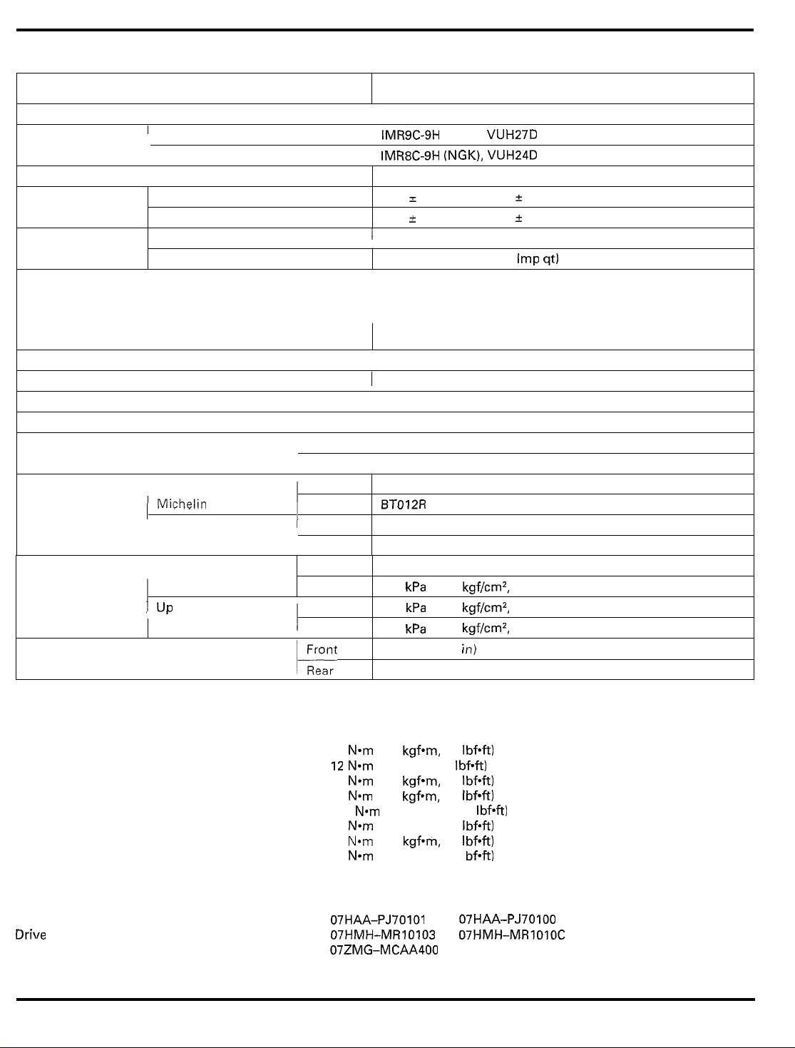
Spark plug
Spark plug gap
Valve clearance IN
Engine oil capacity
Drive chain slack
Recommended brake fluid
'
Standard
1
Optional
EX
At draining
At oil filter change
I
I
Michelin
1
Rear
Front
1
Rear
1
IMR9C-9H (NGK), VUH27D (DENSO)
1
IMR8C-9H (NGK), VUH24D (DENSO)
-
0.9 mm (0.03 - 0.04 in)
0.8
0.16
I
0.03 mm
0.27
2
0.03
i
3.5 liter (3.7 US qt, 3.1 Imp qt)
3.7 liter (3.9 US qt, 3.3
1
40 - 50
1
Honda DOT 4 Brake Fluid
BT012R RADIAL G
Pilot SPORT E
Pilot SPORT
mm
(0.006 L 0.001
mm
(0.01
1
(1.6 - 2.0 in)
E
L
0.001 in)
Imp qt)
in)
load
1
up
to
maximum
weight capacity
Minimum tire tread depth
TORQUE
Timing hole cap
Spark plug
Oil
drain bolt
Oil filter cartridge
Rear axle nut
Drive sprocket special bolt
Driven sprocket nut
Rear master cylinder push rod lock nut
VALUES
TOOLS
Oil
filter wrench
Drive chain tool set
Cam chain tensioner holder
Rear 290
1
Front
~
Rear
18
N-m (1.8 kgfom, 13 Ibf-ft)
12 N*m (1.2 kgf-m, 9 Ibf-ft)
29 N*m (3.0 kgfom, 22 IbfW
26 N-m (2.7 kgfmm, 20 Ibf-ft)
113 N-m (11.5 kgf-m, 83 Ibf-ft) U-nut
54
N*m (5.5 kgf-m, 40 Ibf*ft)
64 N*m (6.5 kgf*m, 47 Ibf-ft)
18 N*m (1.8 kgf-m, 13 I bf-ft)
07HAA-PJ70101 or 07HAA-PJ70100
07HMH-MR10103
07ZMG-MCAA400 (U.S.A. only)
kPa (2.90 kgf/cm2, 42 psi)
kPa (2.50 kgf/cm2, 36 psi)
250
290
kPa (2.90 kgf/cm2, 42 psi)
1.5
rnm
(0.06
in)
,
2.0 mm
(0.08
in)
or
07HMH-MRIOIOC (U.S.A. only)
Apply grease to the threads.
oil
Apply clean engine
to the O-ring.
3-2
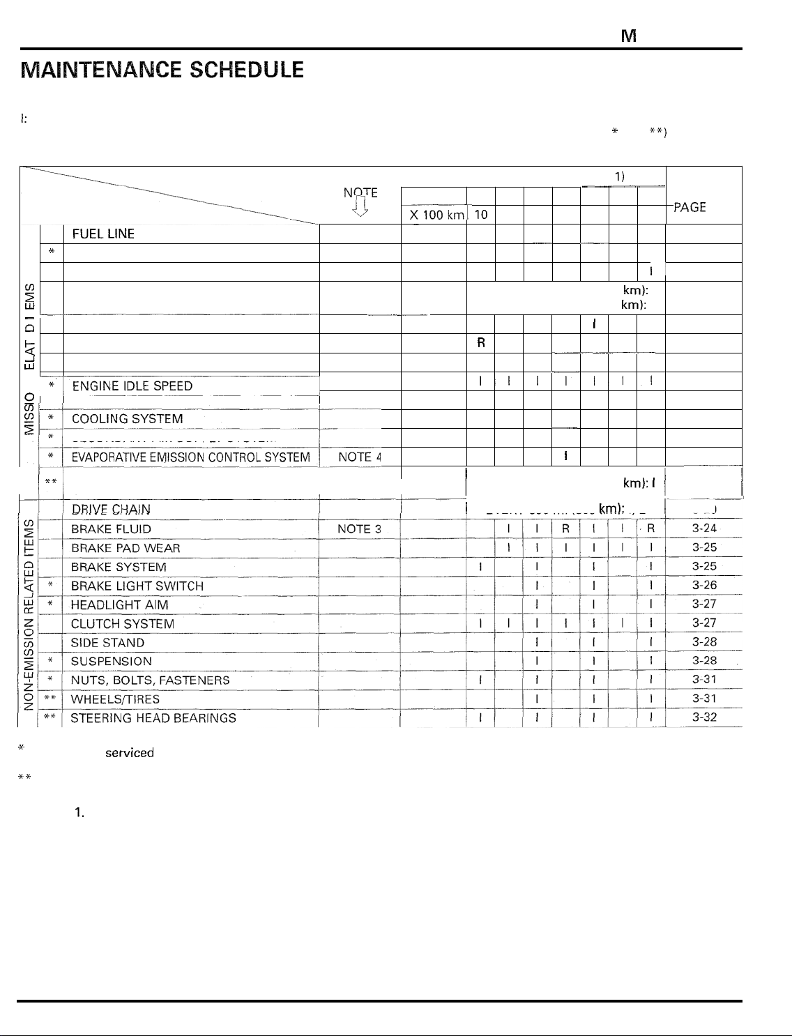
MAINTENANCE
Perform the Pre
I:
Inspect and Clean, Adjust, Lubricate
The following items require some mechanical knowledge. Certain items (particularly those marked
more technical information and tools. Consult their authorized Honda dealer.
ITEMS
*
*
!i
w
I
-
-I
-
a
*
W
2
-I
w
77
0
W
i
/**I
-
ride inspection in the Owner’s Manual at each scheduled maintenance period.
or
Replace
FREQUENCY
if
necessary. C: Clean.
NOTE
0
FUELLINE
THROTTLE OPERATION
AIR CLEANER
SPARK PLUGS
VALVECLEARANCE
ENGINE OIL
ENGINE OIL FILTER
RADIATOR COOLANT NOTE
SECONDARY AIR SUPPLY SYSTEM
EGCV (Exhaust Gas Control Valve)
CONTROL CABLE
NOTE
2
__-___
3
R:
Replace. A: Adjust. L: Lubricate.
ODOMETER READING (NOTE
,
X
1,000 mi
lookm~
-
0.6
10 64
4
I
EVERY
EVERY
R
R R
I
EVERY
I
1
16,000
32,000
IIIIIII
16,000
EVERY
8 12 16 20 24
128
I I
___
I
R
I
I
I
500
______
192
256
__
I
I
mi
(25,600
mi (51,200 km):
I
R R
-~~-
R R
___
I
I
__
I
I
mi
(25,600
mi
(800
*
and
1)
320 384
km):
km):
km):
I,
**I
I
I
I/
I
R
R
I
I
I
I
L
1
,
1
may require
REFER TO
PAGE
3-4
3-5
3-6
-
6
3
3-10
3-15
3-15
3-17
3-18
3-18
3-19
3-19
5-93
3-20
I
*
Should be serviced by an authorized Honda dealer, unless the owner has proper
cally qualified.
**
In the interest of safety, we recommend these items be serviced
NOTES:
1.
At higher odometer readings, repeat at the frequency interval established here.
2.
Service more frequently if the motorcycle
3.
Replace every 2 years,
mechanical skill.
4.
California
type
only
or
at the indicated odometer intervals, whichever comes first. Replacement requires
is
ridden in unusually wet
only
by an authorized Honda dealer.
tools
or
dusty areas.
and service data and
is
mechani
-
3-3
MAINTENANCE
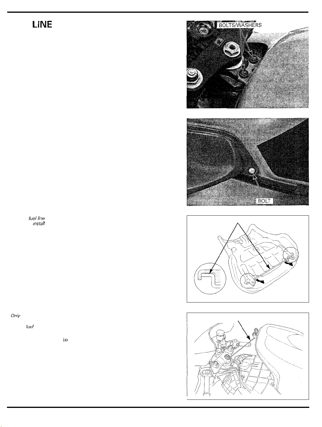
FUEL
LINE
Remove the
washers.
Remove the right and left
front fuel
tank mounting bolts and
duct cover mounting bolts.
After fueiiine
inspection,
the rod ends into
the seat properly
Only use the rod
as
shown
to
support the
fuei tank
mstaii
Remove the seat and then remove the fuel tank sup
port rod from the seat.
Open and support the front end of fuel tank using the
as
support rod
Do
not
lift
sary
to
support
shown.
the front end of fuel tank more than neces
it.
-
-
FUEL
TANK SUPPORT
FUEL
TANK SUPPORT ROD
ROD
3-4
MAINTENANCE
Check the fuel lines for deterioration, damage or leak
age. Replace the fuel line
Install the fuel tank in the reverse order of removal.
if
necessary.
-
THROTTLE OPERATION
Check for smooth throttle grip full opening and auto
matic full closing
the
Check
deteriorated, kinked or damaged.
Lubricate the throttle cables,
not smooth.
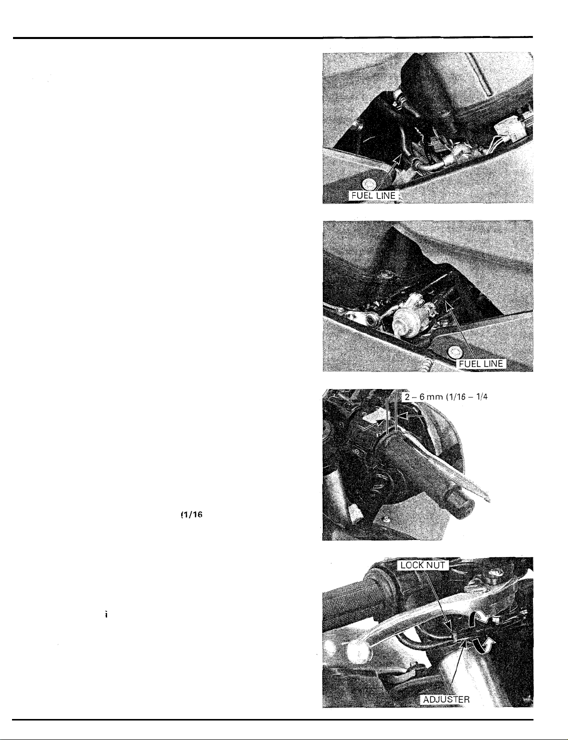
Measure the free play at the throttle grip flange.
FREE
Throttle grip free play can be adjusted at either end
the throttle cable.
Minor adjustments are made
Adjust the free play by loosening the lock nut and
t
u rn i ng the adjuster.
throttle cables and replace them
PLAY:
in
all steering positions.
2
-
6
mm
(1/16
if
throttle operation is
-
1/4
in)
with
the upper adjuster.
if
they are
of
‘4
in)
-
L
%
3-5
MAINTENANCE
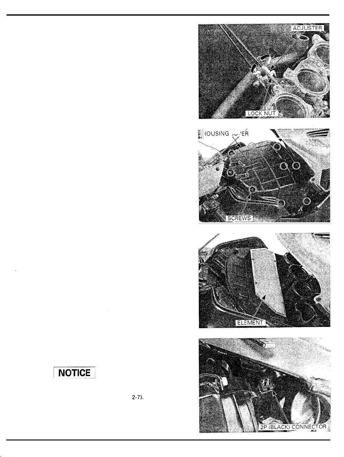
Major adjustments are made with the lower adjuster.
Remove the air cleaner housing (page
Adjust the free play
turning the adjuster.
After adjustment, tighten the lock nut securely.
Recheck the throttle operation.
Replace any damaged parts,
AIR CLEANER
Open and support the front end
3-4).
Remove the screws and air cleaner housing cover.
5-64).
by
loosening the lock nut and
if
necessary.
of
the fuel tank (page
1
HOUSING
e-
COVER
\/
Remove and discard the air cleaner element in accor
dance with the maintenance schedule (page 3Also replace the air cleaner element anytime it is
excessively dirty or damage.
Install the removed parts in the reverse order of
removal.
SPARK PLUGS
REMOVAL
/I
Be
careful not
Remove the lower cowl (page
Disconnect the fan motor wire
to
damage the radiator fins.
2-71.
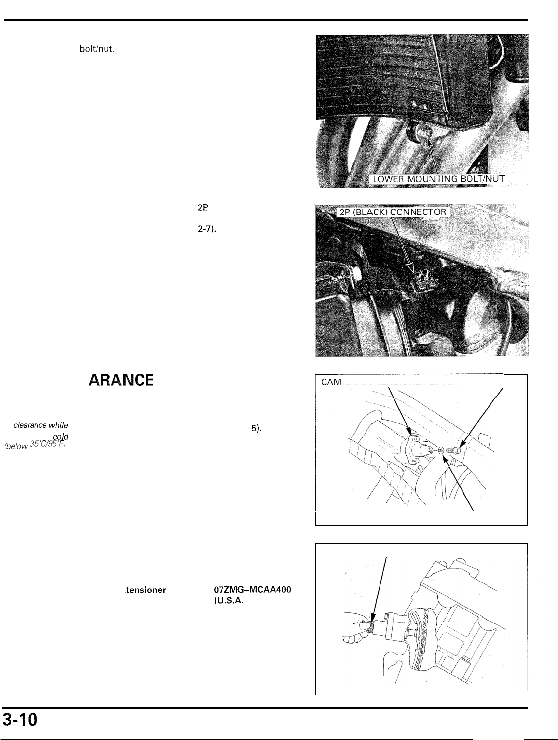
2P
(Black) connector.
-
3).
3-6
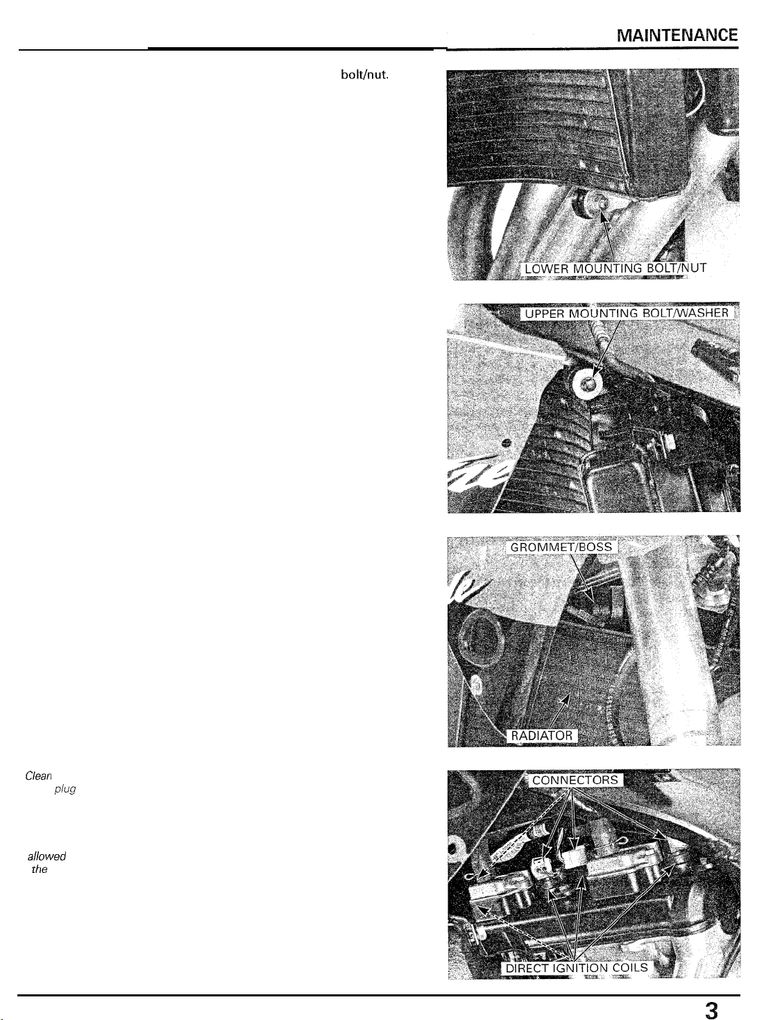
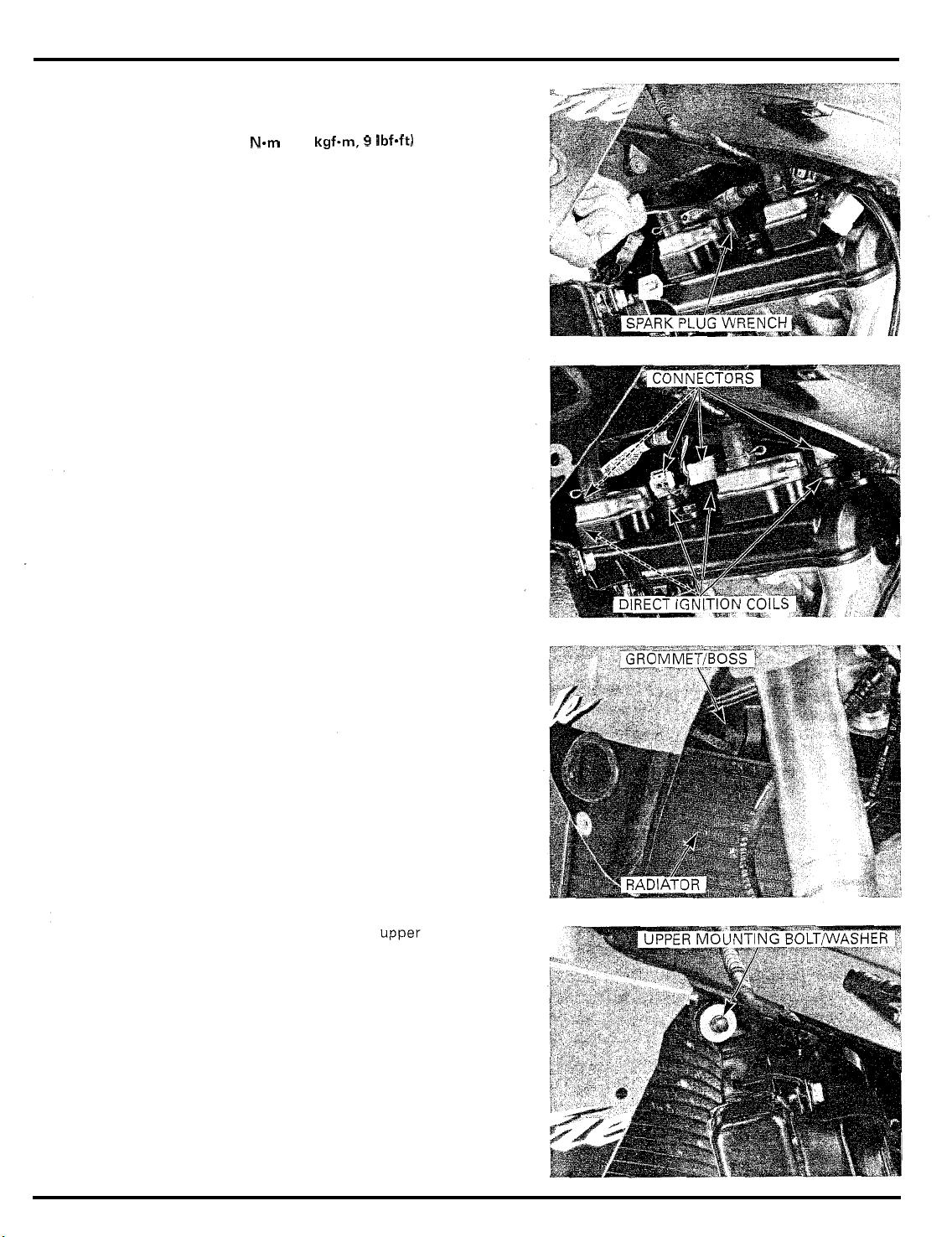
Remove the radiator lower mounting bolthut.
Remove the radiator upper mounting bolt and
washer.
Ciean around the
spark
plug
with compressed
air before remov
ing, and be sure
that no debris
aiiowed to enter
the combustion
bases
chamber
Remove the radiator grommet from the frame
moving
Disconnect the direct ignition coil connectors.
Remove the direct ignition coils from the spark plugs.
-
I
S
it
to the right, then move the radiator forward.
boss
by
-
7
MAINTENANCE
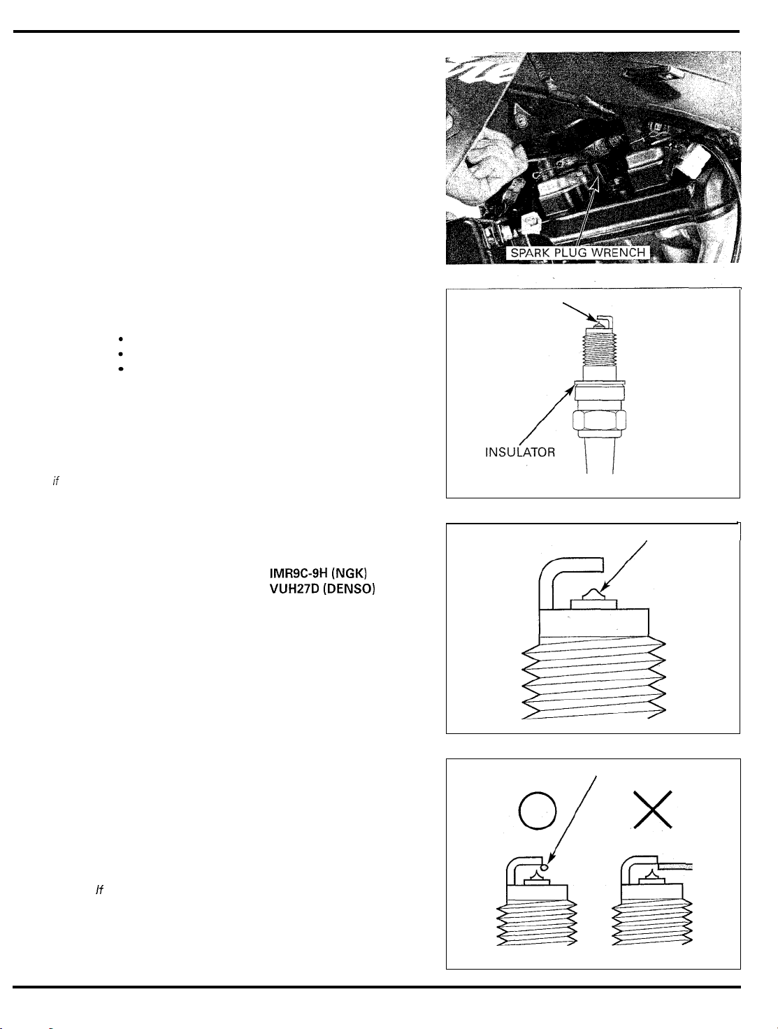
This motorcycle’s
spark plugs are
equipped with
iridium center
electrodes
Replace any spark
plug
If
the elec
trode is contami
nated
Remove the spark plug using the equipped spark
wrench or an equivalent.
Inspect or replace as described in the maintenance
schedule.
INSPECTION
Check the following and replace
mended spark plug: page
Insulator for damage
Electrodes for wear
Burning condition, coloration
If
the electrodes are contaminated with accumulated
objects or dirt, replace the spark plug.
-
-
Replace the plug if the center electrode
shown in the illustration.
3-2)
if
necessary (recom
is
rounded as
plug
-
ELECTRODE
La
ROUNDED ELECTRODE
1
Always use
the specified
spark plugs on
this motorcvcle.
To prevent
damaging the
iridium center
electrode, use a
wire type feeler
gauge to check the
spark plug gap
Do
not adjust the
spark plug gap
the gap is
replace the spark
plug with
out
a
of
new
one
specification,
SPECIFIED SPARK PLUG:
Check the gap between the center and side electrodes
with a wire type feeler gauge.
Make sure the
If
does not insert between the gap.
If the gauge can be inserted into the gap, replace the
plug with a new one.
1.0
mm
IMR9C-9H (NGK)
VUH27D (DENSO)
(0.04
in)
diameter plug gauge
WIRE TYPE FEELER GAUGE
/
3-8
Reinstall the spark plug in the cylinder head and hand
tighten, then torque
to
specification.
MAINTENANCE
TORQUE:
If
using the new plug, install as follows:
Install and hand tighten the new spark plug, then
tighten
tacts the seat of the plug hole.
Install the direct ignition coils.
Connect the direct ignition
12
it
about
N-m
(1.2
kgf-m,
9
IbfW
1/2
turn after the sealing washer con
coil
connectors.
-
Install the radiator grommet onto the frame boss.
Install the washer and
then tighten the bolt.
radiator
mounting bolt,
3-9
MAINTENANCE
Install and tighten
bolthut.
Connect the fan motor wire
Install the lower cowl (page
the
radiator
lower
2P
(Black) connector.
2-7).
mounting
VALVE
inspect and adjust
ciearance whiie
the engine
35‘c’g5W
CLE
the valve
is
coid
INSPECTION
Remove the cylinder head cover (page
Remove the cam chain tensioner lifter
and sealing washer.
Turn the cam chain tensioner lifter shaft
wise) and secure
TOOL:
Cam chain tensioner holder 07ZMG-MCAA400
it
using the special tool.
(U.S.A. only)
-5).
8
sealing bolt
fully
in
(clock
CHAIN TENSIONER LIFTER BOLT
-
CAM CHAIN TENSIONER HOLDER
SEALING WASHER
I
3-70
 Loading...