

Page 1

e
e
e
G
G
G
u
u
u
i
i
i
d
d
d
e
e
e
BBrrootthheerr LLaasseerr PPrriinntteerr
c
n
e
r
e
f
e
R
l
a
c
i
n
h
c
e
T
T
T
c
e
c
e
<<MMOODDEELLSS CCOOVVEERREEDD BBYY TTHHIISS MMAANNUUAALL>>
PP22550000//11666600ee//22006600//22440000CC//22440000CCee//33440000CCNN//
11665500//11667700NN//33226600NN//22446600//77005500//11885500//11887700NN//
First version August, 1999 Created for HL-1050/1070/1250/1270N/
Ver. A March, 2000 Revised for Addition of HL-2400Ce/3400CN
n
h
n
h
HHLL--11005500//11007700//11225500//11227700NN//11445500//11447700NN
55004400//55005500//55007700NN//22660000CCNN//33445500CCNN
i
i
c
c
a
a
l
l
R
R
f
e
f
e
1450/1470N/P2500/1660e/2060/2400C
e
e
r
r
e
e
n
n
c
c
Ver. B March, 2001 Revised for Addition of HL-1650/1670N/3260N/2460
Ver. C October, 2001 Revised for Addition of HL-1450/1470N
Ver. D June, 2003 Revised for Addition of HL-7050/1850/1870N/5050/
5070N
Ver. E September, 2003 Reviced for Addition of HL-2600CN/3450CN.
Ver. F October, 2003 Reviced for Addition of HL-5040.
© Copyright Brother Industries, Ltd. 2001
ALL RIGHTS RESERVED
Page 2

Trademark acknowledgments
Brother is a registered trademark of Brother Industries Ltd.
PostScript is a registered trademark of Adobe Incorporated.
Epson is a registered trademark and FX-850 a trademark of Seiko Epson Corporation.
Hewlett Packard, HP, LaserJet and PCL are registered trademarks and LaserJet, HP-GL, and HP-GL/2 are
trademarks of Hewlett Packard Company.
IBM is a registered trademark and Proprinter XL is a trademark of International Business Machines Corporation.
Microsoft, MS-DOS and Windows are registered trademarks.
Intellifont is a registered trademark of Agfa Corporation.
TrueType is a trademark of Apple Computer, Inc.
All other brand and product names mentioned in this manual are registered trademarks or trademarks of respective
companies.
Compilation and Publication
Under the supervision of Brother Industries Ltd., this manual has been compiled and published, covering the latest
product's descriptions and specifications.
The contents of this manual and the specifications of this product are subjected to change without notice.
Brother reserves the right to make changes without notice in the specifications and materials contained herein and
shall not be responsible for any damages (including consequential) caused by reliance on the materials presented,
including but not limited to typographical and other errors relating to the publication.
Page 3

i
TABLE OF CONTENTS
GLOSSARY
CHAPTER 1 INTRODUCTION
1. ABOUT THE MANUAL----------------------------------------------------------------------------------- 3
2. AREAS OF USE ------------------------------------------------------------------------------------------- 4
CHAPTER 2 PCL
1. COMMAND LIST ------------------------------------------------------------------------------------------ 7
2. INTRODUCTION -----------------------------------------------------------------------------------------10
3. CONTROLLING THE PRINTER----------------------------------------------------------------------11
4. JOB CONTROL -------------------------------------------------------------------------------------------15
5. USHING FONT--------------------------------------------------------------------------------------------35
6. USING GRAPHICS --------------------------------------------------------------------------------------68
7. MACROS ---------------------------------------------------------------------------------------------------88
8. STATUS READBACK -----------------------------------------------------------------------------------94
9. INDEX ----------------------------------------------------------------------------------------------------- 102
CHAPTER 3 PCL5C
1. INTRODUCTION ------------------------------------------------------------------------------------------ 3
2. COLOR MODES ------------------------------------------------------------------------------------------- 4
3. COLOR PALLETS----------------------------------------------------------------------------------------10
4. COLOR GRAPHICS -------------------------------------------------------------------------------------12
5. ENHANCE OUTPUT ------------------------------------------------------------------------------------14
6. HP-GL/2-----------------------------------------------------------------------------------------------------16
7. INDEX -------------------------------------------------------------------------------------------------------18
CHAPTER 4 HP-GL/2 GRAPHICS LANGUAGE
1. COMMOAND LIST ---------------------------------------------------------------------------------------- 4
2. INTRODUCTION ------------------------------------------------------------------------------------------ 6
3. TERMINOLOGY ------------------------------------------------------------------------------------------- 7
4. COMMAND SYNTAX------------------------------------------------------------------------------------- 9
5. THE HP-GL GRAPHICS WINDOW ------------------------------------------------------------------10
6. PREPARING TO PRINT GRAPHIC IMAGES -----------------------------------------------------11
7. COMMANDS-----------------------------------------------------------------------------------------------12
8. INDEX -------------------------------------------------------------------------------------------------------52
CHAPTER 5 PJL PRINTER JOB LANGUAGE
1. INTRODUCTION ------------------------------------------------------------------------------------------ 4
2. HOW TO USE PJL ---------------------------------------------------------------------------------------- 8
3. COMMAND GROUP-------------------------------------------------------------------------------------- 9
4. KERNEL COMMANDS----------------------------------------------------------------------------------10
5. JOB SEPARATION COMMANDS--------------------------------------------------------------------13
6. ENVIRONMENT COMMANDS------------------------------------------------------------------------15
7. STATUS READBACK COMMANDS-----------------------------------------------------------------40
8. DEVICE ATTENDANCE COMMAND ---------------------------------------------------------------56
9. INDEX -------------------------------------------------------------------------------------------------------59
Page 4

i
CHAPTER 6 EPSON FX-850
1. COMMAND LIST ------------------------------------------------------------------------------------------ 3
2. INTRODUCTION ------------------------------------------------------------------------------------------ 5
3. EMULATION DETAILS ---------------------------------------------------------------------------------- 6
4. TERMINOLOGY ------------------------------------------------------------------------------------------- 7
5. CONTROLLING THE PRINTER----------------------------------------------------------------------- 8
6. COMMANDS------------------------------------------------------------------------------------------------ 9
7. INDEX -------------------------------------------------------------------------------------------------------26
CHAPTER 7 IBM PROPRINTER XL
1. COMMAND LIST ------------------------------------------------------------------------------------------ 3
2. INTRODUCTION ------------------------------------------------------------------------------------------ 5
3. EMULATION DETAILS ---------------------------------------------------------------------------------- 6
4. NOTATION USED IN THIS EMULATION DESCRIPTION ------------------------------------- 7
5. COMMANDS------------------------------------------------------------------------------------------------ 8
6. INDEX -------------------------------------------------------------------------------------------------------21
CHAPTER 8 BARCODE CONTROL
1. INTRODUCTION ------------------------------------------------------------------------------------------ 3
2. PRINT BAR CODES OR EXPANDED CHARACTERS------------------------------------------ 4
3. DEFINITION OF PARAMETERS---------------------------------------------------------------------- 5
4. EXAMPLE PROGRAM LISTINGS -------------------------------------------------------------------10
CHAPTER 9 HP-GL GRAPHICS LANGUAGE
1. COMMAND LIST ------------------------------------------------------------------------------------------ 3
2. INTRODUCTION ------------------------------------------------------------------------------------------ 4
3. COMMANDS------------------------------------------------------------------------------------------------ 6
4. INDEX -------------------------------------------------------------------------------------------------------27
APPENDIX A COMPARISON LIST
APPENDIX B FLASH/PCMCIA CARD COMMANDS
APPENDIX-C HBP MODE COMMANDS
APPENDIX D REFERENCE LIST OF MX-2000 SERIES UNIQUE
COMMANDS
APPENDIX E REFERENCE LIST OF FS-5050 UNIQUE COMMANDS
i
Page 5

GLOSSARY
Absolute plotting A method of plotting in the HP-GL and HP-GL/2 graphics language where
coordinates are specified relative to the origin of the coordinate system currently in
use.
Anchor point The top left-hand corner of the PCL picture frame. You can position this on the
page using a PCL command.
Anisotropic scaling A form of image scaling using the SC command in HP-GL and HP-GL/2 mode in
which the user units can be of different sizes. Hence the entire graphics window
can be used to display the image.
The standard system for assigning number codes (0 ~ 255) to alphabetic, numeric
ASCII
and control code characters.
Attribute A characteristic of a downloadable font or a character of a Downloadable font that
is represented by a number of a fixed length.
Bitmap font A font whose characters are defined as raster images. The characters that make up
a bitmap font are of a fixed size.
Bold A wider line thickness for typographical characters, used to make the text stand
out, for example, in headings.
Calling a macro A way of running a macro in which changes to the modified print environment are
not retained when the macro has finished running.
Cartridge A storage medium that you can insert into the printer cartridge slots. Cartridges
can store fonts. The advantage of using cartridges is that they allow you to use
more fonts without taking up printer memory space.
Cartridge font A font that is stored on a cartridge. These are widely available commercially.
Character cell
Character code A number assigned to a character that uniquely identifies it.
Character descriptor A block of data that describes the characteristics of an individual character in a
Character set A selection of different characters. Characters sets normally include the alphabet
Column
Control code An ASCII code that tells the computer to perform a particular function, such as a carriage return.
The imaginary grid on which downloadable characters are designed.
downloadable font, such as its width and height.
in both upper- and lowercase, the digits' 0-9, punctuation marks, common
mathematical symbols and a few other useful characters. There are also some
specialized character sets that are used for specific applications like mathematics.
A font is defined as having a particular character set.
A vertical sub-division of the page whose width is equal to the HMI (horizontal
motion index). The print position moves across the page one column width when
any single character is printed ( in a monospaced font), or when a space character
is printed ( in a proportionally spaced font). See also HMI.
iii
Page 6

Control panel reset
A reset or factory reset performed using the printer control panel.
Cross-hatching A method of shading using perpendicular diagonal lines that cross one another.
Current units The current unit type in use in HP-GL and HP-GL/2 mode. Current units are either
user units or graphics units depending on whether an SC command has been used.
Cursor Although the printer does not have a cursor, it is sometimes easier to visualize the
printer's operation in terms of a cursor that can be moved from place to place on the
page.
Cursor position
The current position of the imaginary cursor.
Decipoint A unit of measure equal to 1/720".
Default conditions A set of HP-GL and HP-GL/2 mode settings that you restore using the DF;
command. The default conditions are a subset of the initial settings.
Destination image The graphic image that is already in place on a page and to which the source image
is applied in the LaserJet series print model.
Dots A unit of measure equal to 1/600", the smallest increment that the cursor can
move.
Downloadable font A character font that can be downloaded from your computer to the printer. You
can either buy Downloadable fonts or create your own. A downloadable font
consists of a font descriptor block followed by a character code, character
descriptor block and the data for each character in the font.
Downloading The process of sending either a font, a macro or a graphic image from your
computer to the printer.
Effective window
The area of the page on which HP-GL and HP-GL/2 output can appear. The
effective window is determined by the overlap of the logical page, the PCL picture
frame, the hard clip and the soft clip limits.
Emulation mode A mode of operation in which the printer imitates the functions of a different
model.
Enabling a macro for overlay
A macro that is enabled for overlay runs as the final operation before each page is
printed, using the macro overlay environment printer settings.
Escape sequence The Esc character followed by a string of other characters that tell the printer which
operation to perform.
Factory default environment The collection of printer settings that have been made to the printer before it leaves
the factory. You can reset the printer to the factory settings either by using a
printer command or using the control panel.
Factory reset
A reset in which LaserJet mode is made the current emulation mode and the factory
default environment is restored.
Fill A shading applied to a shape that you have drawn.
Fixed spacing See monospacing.
iv
Page 7

A collection of characters that are designed to work in harmony together. A font
Font
has several characteristics that identify it uniquely: character or symbol set,
spacing, pitch, height or point size, style, stroke weight and typeface. Fonts can
either be resident in the printer's ROM, installed on cartridge or downloaded from
your computer. You can either buy downloadable fonts commercially or create
your own. The word "font" is often wrongly used to mean "typeface". A font is
confined to a single height or point size whereas a typeface is not.
Font descriptor A block of data that is downloaded to the printer as the first part of a downloaded
font. The font descriptor describes the characteristics that are common to every
character in the font, such as stroke weight, and contains other relevant
information.
Graphics mode initial settings
The HP-GL and HP-GL/2 mode settings that are in effect when you enter HP-GL
and HP-GL/2 mode. You can restore the initial conditions using the IN; command.
Graphics units
The default units of the HP-GL and HP-GL/2 coordinate system. Also sometimes
called plotter units.
Graphics window The area on the page in which HP-GL and HP-GL/2 graphic images can appear.
Initially this is the same as the picture frame, but you can change the size, position
and aspect ratio of the graphics window using the IW command.
Gray scale A degree of continuous shading ranging from 0%, white, to 100%, black.
Hard clip limits The area of the page on which it is physically possible to print using HP-GL and
HP-GL/2 graphics language commands. The hard clip limits are determined by the
size of the physical page and are equivalent to the LaserJet mode printable area.
Hatching
A method of shading using parallel lines.
Height The height in typographic points (1/72" units) of an unaccented capital letter in a
font.
HMI Horizontal motion index. The horizontal distance that the print position moves
across the page when any single character is printed ( in a monospaced font ), or
when a space character is printed ( in a proportionally spaced font ). You can set
the HMI using printer commands, however, when you alter any font characteristic
( in effect, select a new font ) or switch between the primary and secondary fonts,
the HMI is reset to its default value based on the newly selected font.
Horizontal plot size The original horizontal size of an imported HP-GL and HP-GL/2 image.
Internal font A font that is stored in the printer ROM and is therefore always available for use,
for example, Brougham 10 pitch, or a font generated from a scalable typeface
stored in the printer's ROM, for example, Tennessee bold 15 pt.
Isotropic scaling
A form of image scaling using the SC command in HP-GL or HP-GL/2 mode in
which the user units must be of equal size. Hence it may not be possible to use the
entire graphics window to display the image.
Justification The way in which text is aligned. For example, left justification involves aligning
the left end of every line of text.
Label A text string that forms part of an HP-GL and HP-GL/2 plot.
Landscape The orientation in which the top edge of the page is longer than the side edges.
v
Page 8

Logical page
The area of the physical page on which the cursor can be positioned in LaserJet
mode. You can use PCL commands to specify the position of the logical page on
the physical page. Also known as the PCL addressable area.
LSB i) The least significant byte of a set of data bytes.
ii) The least significant bit of a single byte of data.
Macro A sequence of PCL commands that can be stored in the printer memory. To run
the sequence you need only use a single PCL command.
Macro execution Executing a macro is a way of running a macro whereby any changes made to the
modified print environment by the macro are retained when macro execution has
been completed.
Macro overlay environment Used only by a macro that has been enabled for overlay. A combination of the user
default environment and the modified print environment.
Medium The line thickness of normal type.
Modified print environment The collection of all current LaserJet printer settings. This environment is saved if
you call a macro or enter HP-GL and HP-GL/2 mode, it is restored when the
macro has finished running or when you quit HP-GL or HP-GL/2 mode.
Monospacing Some bitmap fonts are printed with each character occupying the same space on a
line of text. This is known as monospacing.
i) The most significant byte of a set of data bytes.
MSB
ii) The most significant bit of a single byte of data.
Pattern
i) The hatching or cross-hatching that can be applied to an outline shape.
ii) The non-white areas of the source image in the LaserJet print model.
Pattern transparency The patterned ( non-white ) areas of the source image are either transparent, in
which case the destination image is visible through the white parts of the pattern,
or opaque, in which case the destination image is not visible at all throughout the
patterned areas of the source image.
PCL Printer Control Language. The language consisting of escape sequences that is
used to control the printer in LaserJet mode
PCL addressable area See logical page.
PCL picture frame
See picture frame.
Pen Although this printer is a laser printer the HP-GL/2 and HP-GL graphics languages
retains the notion of a pen and allows you to select between two pens, white and
black. You must select a pen before you can draw anything. The HP-GL and HPGL/2 language were originally developed for use with plotters and the terminology
remains.
Perforation skip A feature whereby the printer automatically compensates for a page break and
resumes printing from the top of the text area on the next page.
Permanent font A downloaded font that is retained when a printer reset is performed.
Permanent macro
A macro stored in the printer that will not be erased if the printer is reset.
vi
Page 9

Physical page
The paper or envelope on which the printer prints.
Picture frame The area of the physical page in which HP-GL and HP-GL/2 graphic images can be
printed.
Pitch The number of characters in one inch of text. Only applicable to monospaced
(fixed pitch fonts.)
A drawing produced using the HP-GL and HP-GL/2 graphics language. So called
Plot
because the language was originally invented for use with plotters.
Plotter units
See graphics units.
Point The standard unit of measurement for character height. Equal to 1/72".
Point factor scaling A form of image scaling using the SC command in HP-GL or HP-GL/2 mode in
which the user units and the location of the scaling point P1 are specified in terms
of graphics units.
Point size
See height.
Polygon A shape consisting of one or more closed groups of connected lines.
Polygon buffer An area of printer memory in which you can store one or more polygons and sub-
polygons defined using HP-GL and HP-GL/2 commands. Some HP-GL and HPGL/2 commands use the polygon buffer automatically.
Portrait The orientation in which the side edges of the page are longer than the top edge.
Posture A component of a font's style - whether it is upright or italic.
Primary font
In LaserJet mode the printer maintains two current font settings. The primary font
is the first of these.
Print model
A way of describing the interaction between different graphic elements ( source
image, pattern and destination image ).
Printable area The area of the page on which the printer can print.
Print position The position from which printing of the next character or graphic object will begin,
providing that no operations that change the print position are performed in the
interim.
Proportional spacing Fonts intended for high quality typographic output use a method of character
spacing in which the space occupied by a single character on a line of text depends
on the individual design of the character. This is known as proportional spacing.
Scalable fonts are almost invariably proportionally spaced.
RAM Random Access Memory. The printer's memory in which fonts and macros can be
stored and where pages that are to be printed are composed.
Raster graphics A method of representing a graphic image as a series of zeroes and ones that
correspond to white and black dots respectively.
Relative plotting A method of plotting in the HP-GL and HP-GL/2 graphics language where
coordinates are specified relative to the point at which the last graphics command
terminated.
vii
Page 10

When you reset the printer you restore a base set of conditions. A reset can either
Reset
be performed using the control panel or by sending the printer a reset command.
There are two types of reset, the normal reset and factory reset. A normal reset
simply restores the current emulation mode with the most recent control panel
settings -- it does not change the emulation mode itself. A factory reset makes
LaserJet mode the current emulation mode and restores the factory default
environment.
Resident font See internal font.
Read Only Memory. Part of the printer's memory that contains the software
ROM
controlling the printer and the printer internal fonts. The ROM cannot be altered
unless the type of ROM fitted to the printer is Flash ROM, in which case it can be
written to electronically via the parallel port of the printer .
A horizontal sub-division of the page whose height is equal to the VMI (vertical
Row
motion index). The print position moves down the page a distance equal to the row
height when a line feed is performed.
Sans serif A kind of typeface normally used for headlines. Sans serif typefaces do not have
little hooks (serifs) on the individual characters. This helps Sans serif headline text
stand out more prominently.
Scalable fonts A font for which you can specify the character size. The printer will automatically
scale the characters to the size you require.
Scaling In HP-GL or HP-GL/2 mode you can use the SC command to scale graphic images.
The three types of scaling are known as anisotropic, isotropic and point factor
scaling.
Scaling points
Two imaginary points called P1 and P2 that define a rectangular area relative to the
picture frame. You can use the HP-GL or HP-GL/2 SC and IP or IR commands to
transform and scale images by changing the relationship between the two scaling
points.
Scalable typeface
A typeface for which you can choose a point size (height) in order to obtain a
particular font for printing. For example, you might select the Utah typeface and
then select 14 pt. as the height. The printer has many resident typefaces. You can
also buy scalable typeface cartridge and disks.
Secondary font
In LaserJet mode the printer maintains two current font settings. The secondary
font is the second of these.
Serif A kind of typeface normally used for body text. Serif typefaces have little hooks
(serifs) on the individual characters that makes text more readable.
Soft clip limits See graphics window. The soft limits are determined by the IW command.
Source image
The graphic image that is applied to the destination image in the LaserJet print
model. The interaction of the two images is determined by the current source and
pattern transparency settings.
Source transparency The source image is either transparent, in which case the destination image is
visible throughout the white parts of the source image, or opaque, in which case
the destination image is not visible at all through the source image.
Spacing The way in which a font's characters are arranged on a line of text. See
monospacing and proportional spacing.
viii
Page 11

Stick font
The default HP-GL and HP-GL/2 font consisting of thin lined characters.
Stroke weight The thickness of the lines that comprise the characters in a particular font.
Medium, bold and light stroke weights are commonly used.
Sub-polygon A shape consisting of a closed group of points connected by lines. Several sub-
polygons can form one polygon.
Symbol set
See character set.
Tab channel A set of up to sixteen vertical tab stops. Up to eight vertical tab channels can be set
up in the Epson FX-850 mode.
Temporary font A downloaded font that is erased from the printer's memory when a printer reset is
performed. To use the font again you must download it again.
Temporary macro A macro that is erased from the printer's memory when a reset is performed. If you
want to use the macro again you must redefine it and download it to the printer
again.
Text area The area of the physical page on which the printer can place text.
Text direction
The orientation of printed text relative to the physical page.
TIFF Tagged Image File Format. A common file format used for storing raster graphics
data.
Transparency
See pattern transparency and source transparency.
Typeface The design style of a set of typographic characters. The character design is
intended to make the characters work together cohesively to produce readable text.
The word "font" is often erroneously used to mean "typeface".
User default environment The current combination of LaserJet factory default settings and settings made
using the control panel. This is the environment that is in effect when you switch
on the printer in LaserJet mode or change to LaserJet emulation from another
emulation mode. You can reset the printer to its user default settings either by
using a printer command or using the control panel.
User units Coordinate units specified by the user with the HP-GL and HP-GL/2 SC command.
Vector graphics A method of defining graphic images in terms of coordinates, points and lines.
The HP-GL and HP-GL/2 graphics languages use this method.
Vertical plot size The original vertical size of an imported HP-GL and HP-GL/2 image.
VMI Vertical motion index. The vertical distance that the print position moves down the
page when a line feed is performed. This can be set using printer commands or
with the printer's control panel by adjusting the "Lines" menu option in PAGE
FORMAT MODE.
ix
Page 12

Page 13

10/10/03
CHAPTER 1
INTRODUCTION
CHAPTER 1 INTRODUCTION - 1
Page 14

10/10/03
CONTENTS1.
2.
AREAS OF USE ........................................................................................................4
2.1 Using Word Processing Packages and Spreadsheets........................................................ 4
2.2 Graphics..............................................................................................................................4
2.3 Programming....................................................................................................................... 4
2.4 Font Development............................................................................................................... 5
.............................................................................................
ABOUT THE MANUAL 3
CHAPTER 1 INTRODUCTION - 2
Page 15

1. ABOUT THE MANUAL
This technical reference manual is intended to help you get the most out of each of the emulation modes
supported by your HL-Series laser printer. It is divided into nine sections - this introductory section and one
section for each of the emulation modes. Each emulation mode section describes the software commands (the
escape sequences and control codes) that you can use to make the printer perform each of its available
functions. Some example programs are included to give you useful ideas.
This manual is for our PCL models. For the differences between each model, see the Appendix "Model
Comparison."
“PCL6” includes both “PCLXL” and “PCL5e”.
As for “PCL5e”, it is described in “chapter 2 PCL” of this manual.
As for “PCLXL”, it is mainly used with Windows driver, and its command is structured by binary code.
Therefore, it is not described in this manual.
For basic set-up information, such as how to connect the printer to your computer, look in the User’s guide.
The User’s guide also describes the printers control panel and how you can set various options using the
keys.
10/10/03
CHAPTER 1 INTRODUCTION - 3
Page 16

10/10/03
2. AREAS OF USE
There are several different applications for which you may want to use your HL-Series laser printer. Four
general areas are outlined in the following sections.
2.1 Using Word Processing Packages and Spreadsheets
You may simply wish to use the printer with your software application packages, such as word-processors or
spreadsheets. Many software packages automatically send commands to the printer requesting particular type
styles, character sizes and specifying page set-up information and other relevant data. In this case you will
not need to use this manual, as your software package will perform the task of controlling the printer for you.
Other packages allow you to embed software commands within your word-processed or spreadsheet
documents. This manual describes the commands you need, and you can simply include them in the form
that your package requires. In either case, read the documentation that came with your software to find out
its own specific requirements for driving a printer.
2.2 Graphics
HP-GL/2 or HP-GL mode offers many powerful graphic features that enable you to draw and print detailed
images quickly and easily. Many commercial graphic packages, notably computer-aided design applications
programs, produce HP-GL/2 or HP-GL output. LaserJet mode also has several graphics features. You can
either write your own programs to generate images or use existing graphics software.
2.3 Programming
If you are writing software, for example in BASIC or C, to drive the printer, the description and formal
specification of each command will enable you to transcribe them straight into your programs. Below is a
simple example of a program to draw and print a three inch black square. The program is given in both C and
BASIC.
C language program
#include <stdio.h>
main()
{
FILE *prn; /* initialization section */
prn = fopen("PRN","wb");
fprintf(prn,"\33E"); /* Esc E - Reset the printer */
fprintf(prn,"\33%0B"); /* Esc%0B - Enter HP-GL/2 */
fprintf(prn,"IN"); /* Initialize */
fprintf(prn,"SP1PA1024,1024"); /* Select pen 1 & move to 0,0 */
fprintf(prn,"PDFT1RA4096,4096"); /* Draw 3" solid square */
fprintf(prn,"\33%0A"); /* Quit HP-GL/2 & restore original cursor
position */
fprintf(prn,"\33E /* Reset and eject page */
}
BASIC language program
10 LPRINT CHR$(27);"E"; :REM Esc E - Reset the printer
20 LPRINT CHR$(27);"%0B"; :REM Esc%0B - Enter HP-GL/2
30 LPRINT "IN"; :REM Initialize
40 LPRINT "SP1PA1024,1024"; :REM Select pen 1 & move to 0,0
50 LPRINT "PDFT1RA4096,4096"; :REM Draw 3" solid square
60 LPRINT CHR$(27);"%0A"; :REM Quit HP-GL/2 & restore original cursor
position
70 LPRINT CHR$(27);"E"; :REM Reset and eject page
CHAPTER 1 INTRODUCTION - 4
Page 17

2.4 Font Development
In LaserJet mode you can send your own character designs to an HL-Series laser printer and print text using
them. To do this you need first to design your characters on paper. Having done this you can then either
input and download your characters using a commercial software package, or encode your designs
numerically and write your own program to download them.
10/10/03
CHAPTER 1 INTRODUCTION - 5
Page 18

10/10/03
CHAPTER 1 INTRODUCTION - 6
Page 19

10/10/03
CHAPTER 2
PCL
PRINTER CONTROL
LANGUAGE
CHAPTER 2 "PCL" - 1
Page 20

10/10/03
ONTENTS
C
1. COMMAND LIST..................................................................................................................7
2. INTRODUCTION ................................................................................................................10
3. CONTROLLING THE PRINTER.........................................................................................11
3.1. Control Codes ........................................................................................................................... 11
3.1.1. Backspace (08) <08h> .....................................................................................................................11
3.1.2. Line feed (10) <0Ah> ........................................................................................................................11
3.1.3. Form feed (12) <0Ch> ......................................................................................................................11
3.1.4. Carriage return (13) <0Dh> ..............................................................................................................11
3.1.5. Select primary font (14) <0Eh>.........................................................................................................11
3.1.6.
3.1.7. Escape (27) <1Bh>...........................................................................................................................11
3.1.8. Horizontal tab (09) <09h>................................................................................................................11
3.1.9. Space (32) <20h>.............................................................................................................................11
3.2. Escape Sequences................................................................................................................... 12
3.2.1. Line termination ................................................................................................................................12
3.2.2. End-of-line wrap................................................................................................................................12
3.2.3. Display functions mode ....................................................................................................................13
3.3. Environments ............................................................................................................................ 14
3.3.1. Factory default environment .............................................................................................................14
3.3.2. User default environment .................................................................................................................14
3.3.3.
3.3.4. Macro overlay environment ..............................................................................................................14
Select secondary font (15) <0Fh> ....................................................................................................11
Modified print environment ...............................................................................................................14
4. JOB CONTROL..................................................................................................................15
4.1.1. Page size ..........................................................................................................................................15
4.1.2. Output tray ........................................................................................................................................16
4.1.3. Paper source ....................................................................................................................................17
4.1.4. Left long-edge offset registration ......................................................................................................18
4.1.5.
4.1.6. Simplex/duplex printing.....................................................................................................................19
4.1.7. Paper side selection .........................................................................................................................19
4.1.8.
4.1.9. Reset.................................................................................................................................................20
4.1.10. Reset to factory default settings .......................................................................................................20
4.1.11. Reset to user settings .......................................................................................................................20
4.1.12. Printer self test ..................................................................................................................................20
4.1.13. Exit current emulation mode.............................................................................................................21
4.1.14. Change emulation mode ..................................................................................................................21
4.2. The Page .................................................................................................................................. 22
4.2.1.
4.2.2. Printable area ...................................................................................................................................22
4.2.3. Logical page .....................................................................................................................................22
4.2.4.
4.2.5. HP-GL/2 graphics window ................................................................................................................22
4.2.6. Portrait page dimensions..................................................................................................................23
4.2.7. Landscape page dimensions............................................................................................................24
4.2.8. Coordinates ......................................................................................................................................25
Top offset registration.......................................................................................................................19
Job separation command .................................................................................................................20
Physical page ...................................................................................................................................22
Text area...........................................................................................................................................22
CHAPTER 2 "PCL" - 2
Page 21

10/10/03
4.2.9.
Units..................................................................................................................................................25
4.2.10. Unit of measure ................................................................................................................................25
4.2.11. Setting the left and right margins ......................................................................................................25
4.2.12. Resetting the horizontal margins ......................................................................................................26
4.2.13. Setting the top margin.......................................................................................................................26
4.2.14. Setting the vertical motion index (VMI).............................................................................................27
4.2.15. Setting the horizontal motion index (HMI) ........................................................................................27
4.2.16. Setting line spacing...........................................................................................................................28
4.2.17. Text length ........................................................................................................................................28
4.2.18. Page length.......................................................................................................................................29
4.2.19. Perforation skip .................................................................................................................................29
4.2.20. Positioning the cursor .......................................................................................................................30
4.2.21. Vertical positioning............................................................................................................................30
4.2.22. Horizontal position ............................................................................................................................31
4.2.23. Positioning the cursor using control codes.......................................................................................32
4.2.24. Using the cursor position stack.........................................................................................................32
4.2.25. Half line feed .....................................................................................................................................33
4.2.26. Logical page orientation ...................................................................................................................33
4.2.27. Text direction ....................................................................................................................................33
5. USING FONTS ...................................................................................................................35
5.1. Introduction ...............................................................................................................................35
5.1.1.
5.1.2. Bitmap fonts ......................................................................................................................................35
5.1.3. Scalable fonts ...................................................................................................................................35
5.1.4.
5.1.5. Unbound fonts ..................................................................................................................................36
5.1.6. Font sources .....................................................................................................................................36
5.1.7. Internal fonts .....................................................................................................................................36
5.1.8. Card/cartridge fonts ..........................................................................................................................37
5.1.9.
5.1.10. Primary and secondary fonts............................................................................................................37
5.1.11. Specifying the primary font ...............................................................................................................37
5.1.12. Specifying the secondary font ..........................................................................................................37
5.1.13. Selecting the default fonts ................................................................................................................37
5.1.14. Switching between the primary and secondary fonts .......................................................................37
5.1.15. Criteria for font selection...................................................................................................................38
5.1.16. Symbol set ........................................................................................................................................38
5.1.17. Symbol collections ............................................................................................................................38
5.1.18. Type of character spacing ................................................................................................................38
5.1.19. Pitch ..................................................................................................................................................38
5.1.20. Height................................................................................................................................................38
5.1.21. Style ..................................................................................................................................................38
5.1.22. Stroke weight ....................................................................................................................................39
5.1.23. Typeface ...........................................................................................................................................39
5.2. Font Selection Commands........................................................................................................ 40
5.2.1. User-defined symbol sets .................................................................................................................40
5.2.2. Symbol set ID code command..........................................................................................................40
5.2.3. Define symbol set .............................................................................................................................40
5.2.4.
5.2.5. Selecting the symbol set...................................................................................................................42
5.2.6. Selecting the type of character spacing ...........................................................................................44
5.2.7.
5.2.8. Selecting the height ..........................................................................................................................45
Font types .........................................................................................................................................35
Bound fonts.......................................................................................................................................36
Downloadable fonts ..........................................................................................................................37
Symbol set control command ...........................................................................................................42
Selecting the pitch ............................................................................................................................44
CHAPTER 2 "PCL" - 3
Page 22

10/10/03
5.2.9.
Scaling the scalable fonts vertically or horizontally ..........................................................................45
5.2.10. Selecting the style.............................................................................................................................45
5.2.11. Selecting the stroke weight...............................................................................................................46
5.2.12. Selecting the typeface ......................................................................................................................46
5.2.13. Font orientation .................................................................................................................................47
5.2.14. Transparent print data ......................................................................................................................48
5.2.15. Esc&d#D (27)(38)(100)#(68) <1Bh><26h><64h>#<44h> ...............................................................48
5.3. Downloadable font manipulation............................................................................................... 49
5.3.1. Font ID ..............................................................................................................................................49
5.3.2. Operations on downloaded fonts......................................................................................................49
5.3.3. Selecting a downloaded font ............................................................................................................49
5.4. Creating Downloadable Fonts................................................................................................... 50
5.4.1. Downloading .....................................................................................................................................50
5.4.2. Sending the font descriptor...............................................................................................................50
5.4.3.
5.4.4. Sending a character code.................................................................................................................62
5.4.5. Sending a character descriptor and data .........................................................................................62
Unicode symbol index character complement bits ...........................................................................61
6. USING GRAPHICS.............................................................................................................68
6.1. Source, Pattern and Destination ............................................................................................... 68
6.1.1.
6.1.2. Set pattern transparency ..................................................................................................................69
6.1.3. Set area fill identity ...........................................................................................................................70
6.1.4. User-defined pattern command ........................................................................................................71
6.1.5. Set pattern reference point ...............................................................................................................71
6.1.6.
6.1.7. Set pattern type ................................................................................................................................72
6.2. Plotting Rectangles................................................................................................................... 74
6.2.1.
6.2.2. Set rectangle width ...........................................................................................................................74
6.2.3. Set rectangle height ..........................................................................................................................74
6.2.4. Draw filled rectangle .........................................................................................................................74
6.3. Raster Graphics ........................................................................................................................ 76
6.3.1. Positioning the cursor .......................................................................................................................76
6.3.2. Set raster resolution..........................................................................................................................76
6.3.3. Set high resolution control ................................................................................................................76
6.3.4.
6.3.5. Set raster area height .......................................................................................................................77
6.3.6. Set raster area width.........................................................................................................................77
6.3.7. Set raster y-offset .............................................................................................................................77
6.3.8. Set compression mode.....................................................................................................................77
6.3.9. Start raster transfer...........................................................................................................................82
6.3.10. Send raster data ...............................................................................................................................82
6.3.11. Compress transfer graphics .............................................................................................................82
6.3.12. End raster transfer ............................................................................................................................82
6.3.13. Horizontal 1200-dpi image format mode (Raster Graphic Mode 1027) ...........................................84
6.4. Vector Graphics ........................................................................................................................86
6.4.1.
6.5. The Picture Frame ....................................................................................................................87
6.5.1. The default picture frame..................................................................................................................87
6.5.2. Set picture frame anchor point .........................................................................................................87
6.5.3. Set picture frame vertical size ..........................................................................................................87
Set source transparency...................................................................................................................68
User-defined pattern control .............................................................................................................72
Cursor position..................................................................................................................................74
Set raster image orientation .............................................................................................................76
Enter HP-GL/2 mode ........................................................................................................................86
CHAPTER 2 "PCL" - 4
Page 23

10/10/03
6.5.4.
Set picture frame horizontal size ......................................................................................................87
6.5.5. Specify vertical plot size ...................................................................................................................87
6.5.6. Specify horizontal plot size ...............................................................................................................87
7. MACROS............................................................................................................................88
7.1. The Purpose of a Macro ........................................................................................................... 88
7.2. Defining a Macro.......................................................................................................................89
7.2.1. Macro ID ...........................................................................................................................................89
7.2.2. Start macro definition ........................................................................................................................89
7.2.3.
7.3. Running a Macro....................................................................................................................... 90
7.3.1. Execute macro ..................................................................................................................................90
7.3.2. Call macro.........................................................................................................................................90
7.3.3. Enable macro for overlay..................................................................................................................90
7.3.4. Disable macro for overlay .................................................................................................................90
7.4. Handling Macros ....................................................................................................................... 91
7.4.1. Delete all macros ..............................................................................................................................91
7.4.2.
7.4.3. Delete macro ....................................................................................................................................91
7.4.4. Make macro temporary.....................................................................................................................91
7.4.5.
7.4.6. Delete all macros from the storage device .......................................................................................91
7.4.7. Delete macro from the storage device .............................................................................................91
7.4.8. Save macro into the storage device .................................................................................................91
7.4.9. Execute data .....................................................................................................................................92
7.4.10. AppleTalk configuration ....................................................................................................................92
7.4.11. MIO video I/O port control ................................................................................................................93
End macro definition .........................................................................................................................89
Delete all temporary macros.............................................................................................................91
Make macro permanent....................................................................................................................91
8. STATUS READBACK........................................................................................................94
8.1. Introduction ...............................................................................................................................94
8.2. Memory Status request.............................................................................................................94
8.3. Entity Status.............................................................................................................................. 94
8.4. Status Response....................................................................................................................... 94
8.5. Status Response Syntax...........................................................................................................95
8.5.1.
8.5.2. Set status readback location unit......................................................................................................95
8.5.3. Inquire status readback entity...........................................................................................................96
8.5.4. Entity status response ......................................................................................................................96
8.5.5. Font response ...................................................................................................................................96
8.5.6.
8.5.7. Bound scalable fonts ........................................................................................................................97
8.5.8. Unbound scalable fonts ....................................................................................................................97
8.5.9.
8.5.10. Location type 1 (currently selected) font ..........................................................................................97
8.5.11. Font extended response ...................................................................................................................98
8.5.12. Macro response ................................................................................................................................99
8.5.13. Use-defined pattern response ..........................................................................................................99
8.5.14. Symbol set response ........................................................................................................................99
8.5.15. Entity error codes............................................................................................................................100
8.5.16. Free space command.....................................................................................................................100
8.5.17. Font cache ......................................................................................................................................101
Set status readback location type.....................................................................................................95
Bitmap fonts ......................................................................................................................................97
Download fonts .................................................................................................................................97
CHAPTER 2 "PCL" - 5
Page 24

10/10/03
8.5.18.
Memory status response ................................................................................................................101
8.5.19. Memory error response ..................................................................................................................101
8.5.20. Flush all pages command...............................................................................................................101
8.5.21. Echo command ...............................................................................................................................101
9. INDEX...............................................................................................................................102
CHAPTER 2 "PCL" - 6
Page 25

1. COMMAND LIST
Control Codes 11
Escape sequences 12
Esc&k#G Line termination 12
Esc&s#C End-of-line wrap 12
EscY Display function mode 13
EscZ Display function mode 13
Environments 14
Job Control 15
Esc&l#A Page size 15
Esc&l#G Output tray 16
Esc&l#H Paper source 17
Esc&l#U Left long-edge offset registration 18
Esc&l#Z Top offset registration 19
Esc&l#S Simplex/duplex printing 19
Esc&a#G Paper side selection 19
Esc&l1T Job separation command 20
EscE Reset 20
EscCR FD Reset to factory default settings 20
EscCR!#R Reset to user settings 20
Escz Printer self test 20
Esc%-12345X Exit current emulation mode 21
EscCR## Change emulation mode 22
10/10/03
The Page 23
Esc&u#D Unit of measure 26
Esc&a#L Setting the left and right margins 26
Esc&a#M Setting the left and right margins 26
Esc9 Resetting the horizontal margins 27
Esc&l#E Setting the top margin 27
Esc&l#C Setting the vertical motion index (VMI) 28
Esc&k#H Setting the horizontal motion index (HMI) 28
Esc&l#D Setting line spacing 29
Esc&l#F Text length 29
Esc&l#P Page length 30
Esc&l#L Perforation skip 30
Esc&a#R Vertical cursor positioning -rows 31
Esc*p#Y Vertical cursor positioning - units 31
Esc&a#V Vertical cursor positioning - decipoints 31
Esc&a#C Horizontal cursor positioning - columns 32
Esc*p#X Horizontal cursor positioning - units 32
Esc&a#H Horizontal cursor positioning - decipoints 33
Esc&f#S Using the cursor position stack 33
Esc= Half line feed 34
Esc&l#O Logical page orientation 34
Esc&a#P Text direction 34
Using fonts 36
Esc(3@, Esc)3@ Selecting the default fonts 38
SI, SO Switching between the primary and secondary font 38
Esc*c#R Symbol set ID code command 41
Esc(f#W Define symbol set 41
Esc*c#S Symbol set control command 43
Esc(symbol set ID Select the symbol set 43
Esc(s#C, Esc)s#C Select the symbol set 44
Esc(s#P, Esc)s#P Selecting the type of character spacing 45
Esc(s#H, Esc)s#H Selecting the pitch 45
CHAPTER 2 "PCL" - 7
Page 26

10/10/03
Esc(s#V, Esc)s#V Selecting the height 46
EscCR!#H, EscCR!#V Scaling the scalable fonts vertically or horizontally 46
Esc(s#S, Esc)s#S Selecting the style 46
Esc(s#B, Esc)s#B Selecting the stroke weight 47
Esc(s#T, Esc)s#T Selecting the typeface 47
Esc&p#X Transparent print data 49
Esc&d#D, Esc&d@ Underlining text 49
Esc&*c#D Font ID 50
Esc*c#F Operations on downloaded fonts 50
Esc(#X, Esc)#X Selecting a downloaded font 50
Esc)s#W Sending the font descriptor 51
Esc*c#E Sending a character code 63
Esc(s#W Sending a character descriptor and data 63
Using graphics 69
Esc*v#N Set source transparency 69
Esc*v#O Set pattern transparency 70
Esc*c#G Set area fill identity 71
Esc*c#W User-defined pattern command 72
Esc*p#R Set pattern reference point 72
Esc*c#Q User-defined pattern control 73
Esc*v#T Set pattern type 73
Esc*c#A, Esc*c#H Set rectangle width 75
Esc*c#B, Esc*c#V Set rectangle height 75
Esc*c#P Draw filled rectangle 75
Esc*t#R Set raster resolution 77
EscCR ## Set high resolution control 77
Esc*r#F Set raster image orientation 77
Esc*r#T Set raster area height 78
Esc*r#S Set raster area width 78
Esc*b#Y set raster y-offset 78
Esc*b#M Set compression mode 78
Esc*r#A Start raster transfer 83
Esc*b#W Send raster data 83
Esc*b#C Compress transfer graphics 83
Esc*rB End raster transfer 83
Esc*rC End raster transfer 83
Esc*b##W Horizontal 1200-dpi image format mode (Raster Graphic Mode 1027) 85
Esc%#B Enter HP-GL/2 mode 87
Esc*c0T Set picture frame anchor point 88
Esc*c#Y Set picture frame vertical size 88
Esc*c#X Set picture frame horizontal size 88
Esc*c#L Specify vertical plot size 88
Esc*c#K Specify horizontal plot size 88
Macros 89
Esc&f#Y Macro ID 90
Esc&f0X Start macro definition 90
Esc&f1X End macro definition 90
Esc&f2X Execute macro 91
Esc&f3X Call macro 91
Esc&f4X Enable macro for overlay 91
Esc&f5X Disable macro for overlay 91
Esc&f6X Delete all macros 92
Esc&f7X Delete all temporary macros 92
Esc&f8X Delete macro 92
Esc&f9X Make macro temporary 92
Esc&f10X Make macro permanent 92
Esc&f1030X Delete all macros from the storage device 92
Esc&f1036X Delete macro from the storage device 92
Esc&f1038X Save macro into the storage device 92
EscCR!#E Execute data 93
Esc&b#W AppleTalk configuration 93
EscCR!1234#M MIO video I/O port control 94
CHAPTER 2 "PCL" - 8
Page 27

10/10/03
Status Readback 95
Esc*s#T Set status readback location type 96
Esc*s#U Set status readback location unit 96
Esc*s#I Inquire status readback entity 97
Esc*s1M Free space command 101
Esc&r#F Flush all pages command 102
Esc*s#X Echo command 102
CHAPTER 2 "PCL" - 9
Page 28

10/10/03
2. INTRODUCTION
This laser printer provides a complete emulation of the supported Hewlett Packard LaserJet printer. Features
include raster and vector graphics, support for bitmap and scalable fonts and page control. There are many
resident fonts in the printer and you can gain access to more by inserting a font cartridge/card or the storage
device into the printer or by downloading fonts from your computer.
CHAPTER 2 "PCL" - 10
Page 29

3. CONTROLLING THE PRINTER
3.1. Control Codes
Control codes are ASCII codes that tell the printer to perform a given function, such as a carriage return. You
can send these codes to the printer as part of a program.
3.1.1. Backspace (08) <08h>
ASCII code 8. This code moves the cursor one column to the left.
3.1.2. Line feed (10) <0Ah>
ASCII code 10. This code performs a line feed.
3.1.3. Form feed (12) <0Ch>
ASCII code 12. This code ejects the most recently printed page from the printer.
3.1.4. Carriage return (13) <0Dh>
ASCII code 13. This code performs a carriage return.
3.1.5. Select primary font (14) <0Eh>
ASCII code 15. When you send this code to the printer subsequent characters will be printed in the current
primary font. This is explained further in the sub-section entitled “Using fonts”.
10/10/03
3.1.6. Select secondary font (15) <0Fh>
ASCII code 14. When you send this code to the printer subsequent characters will be printed in the current
secondary font. This is explained further in the sub-section entitled “Using fonts”.
3.1.7. Escape (27) <1Bh>
ASCII code 27. You must use this character code to start every instruction sequence that you send to the printer.
3.1.8. Horizontal tab (09) <09h>
ASCII code 9. This code moves the cursor one tab position to the right. The tab positions are at the left margin
and at the left edge of every 8th column as defined by the horizontal motion index (HMI) described in the next
section, entitled “The Page”.
3.1.9. Space (32) <20h>
ASCII code 32. This code moves the cursor one column to the right.
CHAPTER 2 "PCL" - 11
Page 30
10/10/03
3.2. Escape Sequences
Escape sequences, also known as PCL (Printer Control Language) commands, tell the printer which operations
to perform. An escape sequence consists of the Esc character followed by a string of characters which define the
operation to be performed. Some escape sequences require parameter values. These are included in the sequence
as numeric characters. The final letter of an escape sequence must be uppercase: all others must be lowercase.
You can send the printer instructions by embedding escape sequences in programs or in word processed
documents.
In this manual escape sequences are shown as they would be entered, except that the character # in a sequence
indicates that a number should be included at that point in the sequence. If no number is included, the printer
interprets that parameter’s value as 0.
When downloading fonts or sending raster scan images to the printer the final uppercase character of the
sequence is followed by the relevant data.
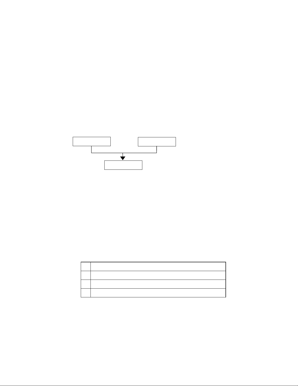
Two escape sequences can be combined into one if the first three characters of each sequence (including the Esc
character itself) are the same. Hence, Esc*c45G and Esc*c2P may be combined to give Esc*c45g2P. The
uppercase ‘G’ which terminated the first sequence becomes a lowercase character in the combined sequence.
Combined escape sequences are executed left to right, so be careful to place commands in the order in which
you want them to be executed.
Esc*c45G
3.2.1. Line termination
You can set the carriage return, line feed and form feed control codes to perform compound functions. You can
either do this using the printer’s control panel (see the User Guide) or by sending the printer the following
escape sequence:
Esc&k#G (27)(38)(107)#(71) <1Bh><26h><6Bh>#<47h>
• 0 = Carriage return, line feed and form feed perform their normal functions.
Esc*c2P
Esc*c45g2P
• 1 = Carriage return performs carriage return/line feed, line feed and form feed perform their normal
functions.
• 2 = Carriage return performs its normal function, line feed performs carriage return/line feed and form feed
performs carriage return/form feed.
• 3 = Carriage return performs carriage return/line feed, line feed performs carriage return/line feed and form
feed performs carriage return/form feed.
0
CR→CR LF→LF FF→FF
1
CR→CR+LF LF→LF FF→FF
2
CR→CR LF→CR+LF FF→CR+FF
3
CR→CR+LF LF→CR+LF FF→CR+FF
3.2.2. End-of-line wrap
If the printer tries to print a line of text that is longer than the width of the text area, the end of the line will
normally be lost. However, you can set the printer to flow text onto the next line so that text is not lost.
You can turn on the automatic text wrap feature either from the printer’s control panel (see the User Guide) or
by sending the printer the following escape sequence:
Esc&s0C (27)(38)(115)(48)(67) <1Bh><26h><73h><30h><43h>
To turn off the facility send:
Esc&s1C (27)(38)(115)(49)(67) <1Bh><26h><73h><31h><43h>
CHAPTER 2 "PCL" - 12
Page 31

10/10/03
3.2.3. Display functions mode
You can choose to make the printer print escape sequences instead of executing them. Send the printer the
following sequence:
EscY (27)(89) <1B><59>
Now the printer prints out escape sequences and prints the characters of the control codes. It does not execute
them. The only exceptions to this are CR, the carriage return code, which causes a carriage return and line feed
to be performed, and the EscZ escape sequence which turns the mode off.
To turn the display functions mode off and enable escape sequences to be executed again send:
EscZ (27)(90) <1B><5A>
The printer exits the display function mode after printing a character of code 1B Hex and the letter "Z". All
subsequent escape sequences and control codes are executed normally and not printed literally.
CHAPTER 2 "PCL" - 13
Page 32

10/10/03
3.3. Environments
3.3.1. Factory default environment
The factory default environment is the collection of printer settings programmed into the printer before it leaves
the factory. You can restore the factory default environment using the printer’s control panel.
See the User's Guide to find how to reset the printer from the printer's control panel.
Some settings cannot be restored to the factory default environment with the RESET operation from the printer's
control panel.
3.3.2. User default environment
The user default environment is a combination of factory default settings and settings which the user has made
from the printer’s control panel or remote printer console. You can store user default setting(s) in the printer by
using the printer control panel. You can restore the user default environment either by sending the reset escape
sequence to the printer, EscE, or by performing a reset from the printer’s control panel. On some models, there
are multiple User settings available, refer to your printer User Guide to see if your printer supports these.
3.3.3. Modified print environment
The modified print environment is made up of all the current printer settings. If you call a macro or go into HPGL/2 graphics language the modified print environment settings are saved. When the macro has been executed,
or when you quit HP-GL/2, these saved settings are restored. The modified print environment consists of
settings for the following features:
Page length
Page size
Orientation
Left registration
Top registration
Paper source
Number of copies
Margins
Perforation skip mode
Line termination mode
End-of line wrap
Current font
Primary font characteristics
Secondary font characteristics HMI
Primary font
Secondary font
Font ID
Character code Macro ID
VMI/Line spacing
Horizontal rectangle size
Vertical rectangle size
Area fill ID
Raster graphics resolution
Raster graphics presentation mode
Raster graphics left margin
Pattern ID
Current pattern
Source transparency mode
Pattern transparency mode
Print direction
Raster graphics compression mode
Underline mode
Raster graphics height
Raster graphics width
3.3.4. Macro overlay environment
The macro overlay environment is a combination of the user default environment and the current modified print
environment. The overlay environments settings take effect when a macro is enabled for automatic overlay. This
is detailed in the section of this manual in which macros are described.
CHAPTER 2 "PCL" - 14
Page 33

4. JOB CONTROL
edge
(JIS)
(JIS)
CO
edge
(JIS)
(JIS)
7
Org
Org
Org
Org
CO
4.1.1. Page size
Esc&l#A (27)(38)(108)#(65) <1Bh><26h><6Ch>#<41h>
# stands for the type of paper or envelope to be used.
Values for # correspond to the paper or envelope sizes shown in the table. Envelopes sizes are shown in the
shaded part of the table.
Model
1 Executive
2 Letter
3 Legal
6 L
r
25 A5
26 A4
27 A3
45 B5
46 B4
100 B5
1024 B6
1025 A5
1026 A6
1028 13"X19"
2048 16"
80 Monarch
81
90
91
M-10
International DL
International C5
Model
1 Executive
2 Letter
3 Legal
6 L
r
25 A5
26 A4
27 A3
45 B5
46 B4
1 POSTCARD
100 B5
101
Free size
1024 B6
1025 A5
1026 A6
1028 13"X19"
1033
1034
1035
1036
anizer J
anizer K
anizer L
anizer M
1038 Folio
2048 16"(A4 Long)
80 Monarch
81
90
91
1037
M-10
International DL
International C5
International DL
Long Edge Feed
HL-1050 HL-1070 HL-1250/
HL-1650/
1670N
P2500
HL-
1270N
HL-
HL-2060 HL-
2400C
1660e
HL-
2400Ce
HL-
3400CN
HL-
3260N
HL-2460 HL-1450/
1470N
HL-7050 HL-1850/1870N/
5040/5050/5070N
HL-2600CN HL-3450CN
10/10/03
CHAPTER 2 "PCL" - 15
Page 34

10/10/03
• When the printer receives this command any unprinted pages are printed and the left, right and top margins
and the text length are set to their factory defaults for the new page size.
• The cursor is moved to the top left of the text area on the new page.
• Depending on your model, you may also set the page size from the printer’s control panel or remote printer
console program (see the User Guide).
• If the paper size you select differs from the size of the currently loaded paper, a message appears in the
control panel prompting you to load the selected size of paper (for HL-1660e, 2060, 2400C/Ce, 3400CN,
3260N 2460, 7050, 1850 and 1870N).
Example)
Select letter size: Esc&l2A <1Bh><26h><6Ch><32h><41h>
Select the width of free size paper: Esc&l#G (1/720 inch unit; for HL-3260N, 2460, 7050, 1850, 1870N,
5040, 5050, 5070N, 2600CN and 3450CN)
Select the height of free size paper: Esc&l#F (1/720 inch unit; for HL-3260N, 2460, 7050, 1850, 1870N,
5040, 5050, 5070N, 2600CN and 3450CN)
4.1.2. Output tray
Esc&l#G (27)(38)(108)#(71) <1Bh><26h><6Ch>#<47h>
# denotes the output tray.
1: Select the printer output tray.
•
3: Select #1 bin.
•
4: Select #2 bin.
•
5: Select #3 bin.
•
6: Select #4 bin.
•
7: Select #5 bin.
•
8: Select #6 bin.
•
9: Select #7 bin.
•
10: Select #8 bin.
•
11: Select #9 bin.
•
12: Select #10 bin.
•
100: Select the finisher tray (HL-3260N)
•
• This command selects the specified output tray.
This command is ignored when the specified tray is not available.
•
• The PJL OUTBIN command is ignored when this command is executed.
• If the printer has data to print when this command is executed, the command is valid from the next page
immediately after the data is printed.
CHAPTER 2 "PCL" - 16
Page 35

4.1.3. Paper source
Esc&l#H (27)(38)(108)#(72) <1Bh><26h><6Ch>#<48h>
# denotes the paper source.
Values for # may be 0, 1, 2, 3, or 4.
• If # = 0 the current page is ejected and the paper source remains the same.
• If # = 1 the current page is printed and the upper cassette becomes the paper source.
• If # = 2 the current page is printed and paper is fed in manually.
• If # = 3 the current page is printed and envelopes are fed in manually.
• If # = 4 the current page is printed and the lower cassette becomes the paper source.
• If # = 4 the current page is printed and the multi-purpose tray becomes the paper source. (HL-
1660e/2060/7050)
• If # = 5, 6 the current page is printed and the lower cassette becomes the paper source.
(HL-1660e/2060/2400C/2400Ce/3400CN/1650/1670N/3260N/2460/7050/1850/1870N/5040/5050/5070N/
2600CN/3450
• If # = 7 the current page is printed and the paper source is auto selected.
• If # = 8 the current page is printed and the lower cassette (Tray 3) becomes the paper source.
(HL-3400CN/3260N/2460/7050)
• If # = 9 the current page is printed and the lower cassette (Tray 4) becomes the paper source.
(HL-3260N/2460/7050)
• If # = 100 the current page is printed and the Tray ID 1 becomes the paper source. (HL-2460/7050)
• If # = 101 the current page is printed and the Tray ID 2 becomes the paper source. (HL-2460/7050)
• If # = 102 the current page is printed and the Tray ID 3 becomes the paper source. (HL-2460/7050)
• If # = 103 the current page is printed and the Tray ID 4 becomes the paper source. (HL-2460/7050)
• If # = 1 or # = 2 either paper or envelopes may be fed in, depending on the current page size setting.
• The cursor is positioned at the top left of the text area on the next page.
10/10/03
CHAPTER 2 "PCL" - 17
Page 36

10/10/03
HL-1050 HL-1060/
#=0 Eject
1070
← ← ← ← ← ← ←
#=1 Sheet Feeder Tray 1
#=2 Manual Feed
#=3 N/A
← ← ← ←
← ←
#=4 N/A Tray 2
#=5 N/A Tray 2
#=6 N/A Tray 2
#=7 Auto
← ← ← ← ← ← ←
HL-1250/
1270N/
P2500
HL1660e
/2060
HL2400C
HL2400Ce
HL3400C
N
HL1450
/1470N
← ← ← ← ← ←
←
Envelope
← ← ←
MP Tray Tray 2
←
← ← ←
←
←
N/A
← ← ← ← ← ←
← ← ← ← ← ←
selection
#=8 N/A
← ← ← ← ←
Tray 3 N/A
HL-1650/1670N/
1850/1870N/
5040/5050/5070N
#=0 Eject
#=1 Tray 1
#=2 Manual Feed
#=3 Envelope
#=4 Tray 2
#=5 Tray 2
#=6 Tray 2
#=7 Auto selection
#=8 N/A Tray 3
#=9 N/A Tray 4
#=100 N/A
#=101 N/A
#=102 N/A
#=103 N/A
HL3260N
HL-2460 HL-7050 HL-
2600CN
HL3450CN
← ← ← ← ←
← ← ← ← ←
← ← ← ← ←
← ← ← ← ←
← ←
MP Tray Tray2 Tray2
← ← ← ← ←
← ←
←
←
← ←
← ←
←
←
←
←
Tray ID 1
Tray ID 2
Tray ID 3
Tray ID 4
N/A Tray2 Tray2
←
←
←
N/A Tray3
N/A N/A
←
←
←
←
N/A N/A
N/A N/A
N/A N/A
N/A N/A
4.1.4. Left long-edge offset registration
Esc&l#U (27)(38)(108)#(85) <1Bh><26h><6Ch>#<55h>
# stands for the distance in decipoints (1/720") that the left edge of the logical page is to be moved.
• Values for # may be in the range -32,767 to 32,767.
• The distance specified is relative to the logical page’s current position.
• # can be positive or negative. Use a positive number to move the logical page to the right on the physical
page, and a negative number to move it to the left.
Positive
Negative
CHAPTER 2 "PCL" - 18
Page 37

10/10/03
Neg
4.1.5. Top offset registration
Esc&l#Z (27)(38)(108)#(90) <1Bh><26h><6Ch>#<5Ah>
# stands for the distance in decipoints (1/720") that the top edge of the logical page is to be moved.
• Values for # may be in the range -32,767 to 32,767.
• The distance specified is relative to the logical page’s current position.
• # can be positive or negative. Use a positive number to move the logical page downwards on the physical
page, and a negative number to move it upwards.
ative
Positive
4.1.6. Simplex/duplex printing
(For HL-1660e/2060/3400CN/1650/1670N/3260N/2460/7050/1850/1870N)
Esc&l#S (27)(38)(108)#(83) <1Bh><26h><6Ch>#<53h>
# can be 0, 1, or 2.
• # = 0 indicates Simplex printing.
• # = 1 indicates Duplex - Long edge binding printing.
• # = 2 indicates Duplex - Short edge binding printing.
• If the optional duplex unit is not installed onto the printer, this mode is set to Simplex mode.
This command setting is not saved in the printer's NV-RAM.
[Long Edge Binding]
[Short Edge Binding]
4.1.7. Paper side selection
Esc&a#G (27)(38)(97)#(71) <1Bh><26h><61h>#<47h>
# can be 0, 1, or 2.
• # = 0 indicates the next side. If there is a page being processed, the printer finishes the processing of that
page. If there are no pages being processed, this command is ignored.
• # = 1 indicates the front face.
If the currently processing page is an odd page, the printer finishes the processing of that page and attaches
a dummy page.
If the odd page has already been processed onto the page and the even page has not been processed yet, only
a dummy page is attached.
If the currently processing page is an even page, the printer finishes the processing of the page.
If both an even and odd page have been processed and the next odd page has not been processed yet, this
command is ignored.
CHAPTER 2 "PCL" - 19
Page 38

10/10/03
• # = 2 indicates the back face.
If the currently processing page is an odd page, the printer finishes the processing of the page.
If the odd page has already been processed onto the page and the even page has not been processed yet, this
command is ignored.
If the currently processing page is an even page, the printer finishes the processing of the page and attaches a
dummy (white) page.
If both an even and odd page have been processed and the next odd page has not been processed yet, only a
dummy (white) page is attached.
4.1.8. Job separation command
(For HL-3260N/2460)
Esc&l1T (27)(38)(108)(49)(84) <1Bh><26h><6Ch><31h><54h>
It is recommended to insert this command at the end of each job.
4.1.9. Reset
EscE (27)(69) <1Bh><45h>
• A printer reset restores the user default environment, deletes any temporary fonts and temporary macros.
• Any pages that have been transmitted are printed out.
• You can also perform a printer reset using the printer’s control panel or remote printer console program (see
the User Guide).
4.1.10. Reset to factory default settings
EscCRFD (27)(13)(70)(68) <1Bh><0Dh><46h><44h>
• This command causes a factory reset to be performed, restoring all the printer’s factory default settings. See
the section “Factory default environment” for a list of the factory default settings.
• You can also perform a factory reset using the printer’s control panel or remote printer console program (see
the User Guide).
4.1.11. Reset to user settings
EscCR!#R (27)(13)(33)#(82) <1Bh><0Dh><21h>#<52h>
• # can be 0, 1 or 2.
• #0 indicates the current settings are restored. Unlike the Esc E reset command, the Esc CR!0R command
resets the input buffer.
• #1 indicates the user settings 1 are restored, if the printer supports multi user settings.
• #2 indicates the user settings 2 are restored, if the printer supports multi user settings (Except for HL-7050).
• Depending on the model, you may be able to lock the control panel settings ("SETTING LOCK=ON"). In
that case, parameters 1 and 2 are ignored.
4.1.12. Printer self test
Escz (27)(122) <1Bh><7Ah>
A printer self test causes a test sheet to be printed out to show that the machine is working properly. Depending
on the model, you may also see the test pattern for HRC setting.
CHAPTER 2 "PCL" - 20
Page 39

4.1.13. Exit current emulation mode
Esc%-12345X (27)(37)(45)(49)(50)(51)(52)(53)(88)
<1Bh><25h><2Dh><31h><32h><33h><34h><35h><58h>
• When the printer receives this command, all page data already received is printed out.
10/10/03
• All settings are reset to the user settings.
• Exits the current emulation mode.
PR2000070
4.1.14. Change emulation mode
EscCRGL (27)(13)(71)(76) <1Bh><0Dh><47h><4Ch>
This command changes the emulation mode to HP-GL mode.
EscCRAB (27)(13)(65)(66) <1Bh><0Dh><41h><42h>
This command changes the emulation mode to BR-Script Batch mode.
EscCRAI (27)(13)(65)(73) <1Bh><0Dh><41h><49h>
This command changes the emulation mode to BR-Script Interactive mode.
EscCRI (27)(13)(73) <1Bh><0Dh><49h>
This command changes the emulation mode to IBM Proprinter XL mode.
EscCRE (27)(13)(69) <1Bh><0Dh><45h>
This command changes the emulation mode to Epson FX-850 mode.
Depending on the model, you can also switch between emulation modes using the printer’s control panel (see
the User Guide).
Emulations available for each model are listed below.
HL-1050
HL-1070
HL-1250
HL-1270N
HL-P2500
HL-1660e
HL-2060
HL-2400C
HL-2400Ce
HL-3400CN
HL-1650/1670N
HL-3260N
HL-2460
HL-1450
HL-1470N
HL-7050
HL-1850/1870N
HL-5040
HL-5050/5070N
HL-2600CN
HL-3450CN
PCL HP-GL BR-Script2 BR-Script3 Epson
FX-850
IBM
Proprinter XL
CHAPTER 2 "PCL" - 21
Page 40

10/10/03
4.2. The Page
4.2.1. Physical page
The physical page refers to the size of the paper or envelope currently in use: A4, Letter, B5, JIS B5, Legal and
Executive are the permitted paper sizes: Monarch, COM-10, International DL and International C5 are the
allowable envelope sizes.
4.2.2. Printable area
The printable area is a rectangular area of the physical page on which the printer can print. Its edges are
approximately 1/6" in from the edges of the physical page, please refer to the printer User Guide for the exact
measurement for each model.
4.2.3. Logical page
The logical page is the area of the physical page where the cursor can be positioned. (Although the printer does
not really have a cursor, we refer to the position on the page from which the printing of a character or graphic
starts as the cursor position). You can alter the size of the logical page using the left offset registration and top
offset registration commands. The logical page is also called the PCL (printer control language) addressable
area.
4.2.4. Text area
The text area is the area of the physical page on which text can be printed, and is determined by the left, right
and top margin settings, the text length and whether the perforation skip facility is on or off. All these settings
can be made either from the printer’s control panel (see the User Guide) or using PCL commands.
4.2.5. HP-GL/2 graphics window
The HP-GL/2 graphics window is the area of the physical page on which images can be printed using HP-GL/2
commands. This is described in the HP-GL/2 section of this manual. The default graphics window is bound by
the left and right edges of the logical page and horizontal boundaries half an inch below the top and above the
bottom of the logical page.
CHAPTER 2 "PCL" - 22
Page 41

10/10/03
l
4.2.6. Portrait page dimensions
(DEFAULT VALUES)
G
E
G
G
H
H
C
F
Physical page
Printable area
Logical page
E
B
D
G
F
B
D
F
Default HP-GL/2 picture frame
Physical page length
Maximum logical page length
Distance from edge of physica
edge of logical page
A
PAPER SIZE A B C D E F G H
LETTER 2550 3300 2400 3300 75 0 50 150
LEGAL 2550 4200 2400 4200 75 0 50 150
EXECUTIVE 2175 3150 2025 3150 75 0 50 150
A4 2480 3507 2338 3507 71 0 50 150
B5 2078 2952 1936 2952 71 0 50 150
JIS B5 2148 3030 2010 3030 69 0 50 150
B6 1476 2078 1334 2078 71 0 50 150
A5 1754 2480 1612 2480 71 0 50 150
A6 1240 1754 1098 1754 71 0 50 150
A4 80 character 2480 3507 2400 3507 40 0 40 150
A4 long 2480 4783 2400 4783 40 0 40 150
COM-10 1237 2850 1087 2850 75 0 50 150
MONARCH 1162 2250 1012 2250 75 0 50 150
C5 1913 2704 1771 2704 71 0 50 150
DL 1299 2598 1157 2598 71 0 50 150
A3 3507 4960 3365 4960 71 0 50 150
13"X19" 3900 5700 3750 5700 75 0 50 150
JIS B4 3035 4298 2893 4298 71 0 50 150
Ledger 3300 5100 3150 5100 75 0 50 150
All measurements are in 1/300" units
CHAPTER 2 "PCL" - 23
Page 42

10/10/03
4.2.7. Landscape page dimensions
(DEFAULT VALUES)
G
E
G
G
H
H
C
F
Physical page
Printable area
E
B
D
G
B
D
F
F
Logical page
Default HP-GL/2 picture
Physical page length
Maximum logical page len
Distance from edge of ph
page to edge of logical
A
PAPER SIZE A B C D E F G H
LETTER 3300 2550 3180 2550 60 0 50 150
LEGAL 4200 2550 4080 2550 60 0 50 150
EXECUTIVE 3150 2175 3030 2175 60 0 50 150
A4 3507 2480 3389 2480 59 0 50 150
B5 2952 2078 2834 2078 59 0 50 150
JIS B5 3030 2148 2910 2148 60 0 50 150
B6 2078 1476 1960 1476 59 0 50 150
A5 2480 1754 2362 1754 59 0 50 150
A6 1754 1240 1636 1240 59 0 50 150
A4 long 4783 2480 4665 2480 59 0 50 150
COM-10 2850 1237 2730 1237 60 0 50 150
MONARCH 2250 1162 2130 1162 60 0 50 150
C5 2704 1913 2586 1913 59 0 50 150
DL 2598 1299 2480 1299 59 0 50 150
A3 4960 3507 4842 3507 59 0 50 150
13"X19" 5700 3900 5580 3900 60 0 50 150
JIS B4 4298 3035 4180 3035 59 0 50 150
Ledger 5100 3300 4980 3300 60 0 50 150
All measurements are in 1/300" units
CHAPTER 2 "PCL" - 24
Page 43

10/10/03
4.2.8. Coordinates
The printer control language coordinate system has its origin at the intersection of the left edge of the logical
page and the top margin. The x-coordinate value of the current cursor position increases as the cursor moves
from left to right, the y-coordinate value increases as the cursor moves down the page. The cursor can be
explicitly positioned anywhere on the current logical page using the PCL coordinate system. In addition, the
cursor’s coordinate position will change as text and graphics are printed.
4.2.9. Units
You can specify cursor movement within the PCL coordinate system using one of three different unit systems.
Decipoints
A decipoint is one-tenth of a typographic point measurement = 1/720".
Rows and columns
Using the horizontal motion index (HMI) (Esc&k#H) and vertical motion index (VMI)(Esc&l#C) commands
you can set the width of a column and the height of a row. You can then use the column width and row height as
the units of the coordinate system. The line-spacing command is an alternative to the VMI command.
Units
The unit of measurement used must be defined by the unit of measure command as described in 4.2.10.
4.2.10. Unit of measure
Esc&u#D (27)(38)(117)#(68) <1Bh><26h><75h>#<44h>
• # value can be 96, 100, 120, 144, 150, 160, 180, 200, 225, 240, 288, 300, 360, 400, 450, 480, 600, 720, 800,
900, 1200, 1440, 1800, 2400, 3600, 7200.
• # stands for the unit of measurement in dots per inch.
• The value set by this command is used as the unit setting for use by other setting commands such as
ESC*p#X.
• The default value of # is 300.
Example)
Esc&u300D Esc*p+100x+200Y
move cursor 100/300 inch right and 200/300 inch down.
Esc&u600D Esc*p+100x+200Y
move cursor 100/600 inch right and 200/600 inch down.
4.2.11. Setting the left and right margins
Esc&a#L (27)(38)(97)#(76) <1Bh><26h><61h>#<4Ch>
# stands for the distance between the left edge of the logical page and the left margin in columns.
Esc&a#M (27)(38)(97)#(77) <1Bh><26h><61h>#<4Dh>
# stands for the distance between the left edge of the logical page and the right margin in columns.
The column width is as defined by the HMI. If you subsequently change the HMI, the margin positions that
•
you have set do not change - that is, when you specify margin positions they remain fixed physically until
you specify new ones or reset them to default values.
• You cannot specify a value for the left margin that is greater than the value of the current right margin.
• If the current cursor position is to the left of your new left margin setting, the cursor will be moved to the
new left margin.
• You cannot set the right margin further right than the right edge of the logical page.
CHAPTER 2 "PCL" - 25
Page 44

10/10/03
• If the current cursor position is to the right of your new right margin setting, the cursor will be moved to the
new right margin.
• The factory default left and right margin settings are at the left and right edges of the logical page
respectively.
• Depending on your model, margin settings can be made from the printer’s control panel (see the User
Guide).
10 REM ***** SET AND CLEAR SIDE MARGINS *****
20 ESC$=CHR$(27)
30 WIDTH "LPT1:",255
40 REM --- END OF LINE WRAP ON ---
50 LPRINT ESC$+"&s0C";
60 REM --- LEFT MARGIN SET TO 10 COLUMNS ----
70 LPRINT ESC$+"&a10L";
80 REM --- RIGHT MARGIN SET TO 70 COLUMNS ----
90 LPRINT ESC$+"&a70M";
100 REM --- PRINT "0123456789" 10 TIMES
110 FOR I=1 TO 10
120 LPRINT "0123456789";
130 NEXT
140 LPRINT
150 REM --- CLEAR SIDE MARGIN ----
160 LPRINT ESC$+"9";
170 REM --- PRINT "0123456789" 10 TIMES
180 FOR I=1 TO 10
190 LPRINT "0123456789";
200 NEXT
210 REM --- PAPER EJECT ----
220 LPRINT CHR$(12);
230 END
4.2.12. Resetting the horizontal margins
Esc9 (27)(39) <1Bh><39h>
This command resets the left and right margins to the left and right edges of the logical page respectively.
4.2.13. Setting the top margin
Esc&l#E (27)(38)(108)#(69) <1Bh><26h><6Ch>#<45h>
# stands for the distance between the top of the logical page and the top margin in rows.
The row height is as defined by the VMI. If you subsequently change the VMI (or the line spacing) the top
•
margin position that you have set does not change - that is, when you specify the top margin position it
remains fixed physically until you specify a new one or reset it to a default value.
• The top margin command is ignored if you try to set a margin greater than the current length of the logical
page.
• The top margin command is ignored if the current VMI is 0.
• The factory default top margin setting is half an inch below the top of the logical page.
Depending on your model, the top margin can be set from the printer’s control panel (see the User Guide).
•
10 REM ******* SET TOP MARGIN TO 10 LINES *******
20 REM
30 ESC$=CHR$(27)
40 LPRINT ESC$+"&l10E";
50 LPRINT "10 LINES "
60 LPRINT CHR$(12);
70 END
CHAPTER 2 "PCL" - 26
Page 45

10/10/03
4.2.14. Setting the vertical motion index (VMI)
Esc&l#C (27)(38)(108)#(67) <1Bh><26h><6Ch>#<43h>
# stands for the height of one row in 1/48".
• # can have any value in the range 0-32767.
• The distance specified by the VMI is the vertical distance moved down the page when the printer performs a
line feed. The VMI is also sometimes referred to as the line pitch.
• If you try to set a VMI that is greater than the current length of the logical page the command is ignored.
• Changing the VMI setting does not affect the position of the top margin.
• The factory default setting is 8 - that is, the printer will print six lines of text per inch.
• Depending on your model, you can change the number of lines per page setting from the printer's control
panel or remote printer console. If you change its setting, the VMI will change automatically.
10 REM ***** SETTING THE LINE PITCH *****
20 ESC$=CHR$(27)
30 REM
40 REM --- SET LINE PITCH TO 1/48 INCH ---
50 LPRINT ESC$+"&l1C";
60 FOR I=1 TO 10
70 LPRINT "I can't read."
80 NEXT
90 LPRINT ESC$+"&l8C";
100 LPRINT
110 LPRINT
120 REM --- SET LINE PITCH TO 1/12 INCH ----
130 LPRINT ESC$+"&l4C";
140 LPRINT "line pitch is 1/12 inch"
150 REM --- SET LINE PITCH TO 1/8 INCH ----
160 LPRINT ESC$+"&l6C";
170 LPRINT "line pitch is 1/8 inch"
180 REM --- SET LINE PITCH TO 1/6 INCH ----
190 LPRINT ESC$+"&l8C";
200 LPRINT "line pitch is 1/6 inch"
210 REM --- SET LINE PITCH TO 1/4 INCH ----
220 LPRINT ESC$+"&l12C";
230 LPRINT "line pitch is 1/4 inch"
240 LPRINT "line pitch is 1/4 inch"
250 REM --- PAPER EJECT ----
260 LPRINT CHR$(12);
270 END
<Sample file 1>
4.2.15. Setting the horizontal motion index (HMI)
Esc&k#H (27)(38)(107)#(72) <1Bh><26h><6Bh>#<48h>
# stands for the width of one column in 1/120".
• # can have any value in the range 0-32767 and can have up to four decimal places.
• If you are using a fixed space font the HMI is the horizontal distance moved across the page when the printer
prints one character.
• If you are using a proportionally spaced font the HMI is the horizontal distance moved across the page when
the printer receives a space control code <20h>.
• If any font characteristics are changed, or a Select Primary Font or Select Secondary Font control code is
sent to the printer, the HMI is set to correspond to the default pitch value of the newly selected font.
• Changing the HMI setting does not affect the positions of the left and right margins.
• The factory default setting is 12 - that is, the printer will print ten characters of fixed pitch text per inch.
CHAPTER 2 "PCL" - 27
Page 46

10/10/03
10 REM ***** SETTING THE CHARACTER PITCH *****
20 ESC$=CHR$(27)
30 REM --- DEFAULT IS 10 CPI PITCH ---
40 LPRINT "10 PITCH "
50 REM --- SET 5 CPI PITCH ---
60 LPRINT ESC$+"&k24H";
70 LPRINT "AAA"
80 REM --- SET 6 CPI PITCH ---
90 LPRINT ESC$+"&k20H";
100 LPRINT "AAA"
110 REM --- SET 8 CPI PITCH ---
120 LPRINT ESC$+"&k15H";
130 LPRINT "AAA"
140 REM --- SET 10 CPI PITCH ---
150 LPRINT ESC$+"&k12H";
160 LPRINT "AAA"
170 REM --- SET 12 CPI PITCH ---
180 LPRINT ESC$+"&k12H";
190 LPRINT "AAA"
200 REM --- SET 0 CPI PITCH ---
210 LPRINT ESC$+"&kH";
220 LPRINT "I CAN'T READ"
230 REM --- PAPER EJECT ----
240 LPRINT CHR$(12);
250 END
<Sample file 2>
4.2.16. Setting line spacing
Esc&l#D (27)(38)(108)#(68) <1Bh><26h><6Ch>#<44h>
# stands for the number of lines to be printed per inch.
• # can have any of the following values: 1, 2, 3, 4, 6, 8, 12, 16, 24 or 48.
• This command performs the same function as the VMI command.
• Changing the line spacing setting does not affect the position of the top margin.
• The factory default setting is 6 - that is, the printer will print six lines of text per inch.
• Depending on your printer model, the number of lines per page can also be set from the printer’s control
panel or remote printer console (see the User Guide).
4.2.17. Text length
Esc&l#F (27)(38)(108)#(70) <1Bh><26h><6Ch>#<46h>
# stands for the number of lines of text (at the current VMI) to be printed on each page.
• Values for # should be within the value (Logical Page length-Top margin).
• Text is printed from the top margin downwards.
• If you specify a value that would cause the text area to extend beyond the end of the logical page, the
command is ignored.
CHAPTER 2 "PCL" - 28
Page 47

Top margin
t
10/10/03
Page leng
Text length
Bottom margin
4.2.18. Page length
Esc&l#P (27)(38)(108)#(80) <1Bh><26h><6Ch>#<50h>
# stands for the length of the logical page in lines (at the current VMI).
• If you specify a page length greater than is allowed by the physical size of the paper in the currently installed
paper tray, a control panel message prompts you to load paper of the appropriate size.
• When the printer receives this command any unprinted pages are printed and the left, right and top margins
and the text length are set to their user defaults.
• If you specify a page length greater than is allowed by any of the supported paper sizes, the command is
ignored.
• If the current VMI is 0 the command is ignored.
• For the USA, the factory default page size is letter, for which the default page length is 66 lines (11 inches at
6 lines per inch). For Europe, the factory default page size is A4, for which the default page length is 70
lines (11.6 inches at 6 lines per inch). The default lengths for other paper sizes are: Legal - 84 lines,
Executive - 63 lines (all at 6 lines per inch).
• Depending on your printer model, you can also set the page length from the printer’s control panel or
remote printer console by setting LINES to the required number of lines per page in the PAGE FORMAT
mode (see the User Guide).
10 REM ******* SETTING THE PAGE LENGTH TO 66 LINES *******
20 REM
30 ESC$=CHR$(27)
40 LPRINT ESC$+"&l66P";
50 FOR I=1 TO 67
60 LPRINT STR$(I)
70 NEXT
80 LPRINT CHR$(12);
90 END
4.2.19. Perforation skip
You can set the printer to flow text from one page to the next when it encounters a line feed (or half line feed)
that would otherwise move the cursor position to below the bottom of the text area. When perforation skip is
enabled the cursor is automatically moved to the top left hand corner of the text area on the next page and
printing continues.
Esc&l#L (27)(38)(108)#(76) <1Bh><26h><6Ch>#<4Ch>
# is either 0 or 1.
# = 0 turns the perforation skip feature off.
•
• # = 1 turns the perforation skip feature on.
• The factory default mode is perforation skip on.
• Whenever the perforation skip mode is changed, the top margin and page length values are reset to their
default values.
CHAPTER 2 "PCL" - 29
Page 48

10/10/03
4.2.20. Positioning the cursor
You can position the cursor anywhere on the logical page. In addition, the cursor position is automatically
changed when text or graphics are printed. You can either position the cursor using absolute PCL coordinate
values or position it relative to the current cursor position, using dots, decipoints or rows and columns as units.
In case of using dots, the units value is defined by the ESC & u # d command. The commands for positioning
the cursor are listed below.
4.2.21. Vertical positioning
Vertical cursor positioning - rows
Esc&a#R (27)(38)(97)#(82) <1Bh><26h><61h>#<52h>
# = number of rows
• A plus or minus sign preceding the number of rows parameter indicates that the cursor is to be positioned
relative to its current position. A signed positive parameter value signifies that the cursor is to be
repositioned vertically downwards on the page, a negative value means that it will be moved upwards.
• An unsigned number as the parameter signifies that the vertical repositioning is absolute - the cursor will be
repositioned the specified number of rows below the top margin, the PCL coordinate system’s x-axis.
• The parameter value can have up to two decimal places.
• The cursor’s horizontal position remains unchanged.
• If you attempt to move the cursor to a position that is outside the boundaries of the logical page, the cursor
will be positioned at either the top or bottom of the logical page as appropriate.
Vertical cursor positioning - units
Esc*p#Y (27)(42)(112)#(89) <1Bh><2Ah><70h>#<79h>
# = number of units
• Units value is defined by the Esc & u # D command.
• A plus or minus sign preceding the number of dots parameter indicates that the cursor is to be positioned
relative to its current position. A signed positive parameter value signifies that the cursor is to be
repositioned vertically downwards on the page, a negative value means that it will be moved upwards.
• An unsigned number as the parameter signifies that the vertical repositioning is absolute - the cursor will be
repositioned the specified number of dots below the top margin, the PCL coordinate system’s x-axis.
• The cursor’s horizontal position remains unchanged.
• If you attempt to move the cursor to a position that is outside the boundaries of the logical page, the cursor
will be positioned at either the top or bottom of the logical page as appropriate.
Vertical cursor positioning - decipoints
Esc&a#V (27)(38)(97)#(86) <1Bh><26h><61h>#<56h>
# = number of decipoints in 1/720"
• A plus or minus sign preceding the number of decipoints parameter indicates that the cursor is to be
positioned relative to its current position. A signed positive parameter value signifies that the cursor is to be
repositioned vertically downwards on the page, a negative value means that it will be moved upwards.
An unsigned number as the parameter signifies that the vertical repositioning is absolute - the cursor will be
•
repositioned the specified number of decipoints below the top margin, the PCL coordinate system’s x-axis.
• The cursor’s horizontal position remains unchanged.
• If you attempt to move the cursor to a position that is outside the boundaries of the logical page, the cursor
will be positioned at either the top or bottom of the logical page as appropriate.
CHAPTER 2 "PCL" - 30
Page 49

10/10/03
4.2.22. Horizontal position
Horizontal cursor positioning - columns
Esc&a#C (27)(38)(97)#(67) <1Bh><26h><61h>#<43h>
# = number of columns
• A plus or minus sign preceding the number of columns parameter indicates that the cursor is to be positioned
relative to its current position. A signed positive parameter value signifies that the cursor is to be
repositioned to the right on the page, a negative value means that it will be moved to the left.
• An unsigned number as the parameter signifies that the horizontal repositioning is absolute - the cursor will
be repositioned the specified number of columns to the right of the left edge of the logical page, the PCL
coordinate system’s y-axis.
• The parameter value can have up to two decimal places.
• The cursor’s vertical position remains unchanged.
• If you attempt to move the cursor to a position that is outside the boundaries of the logical page, the cursor
will be positioned at either the left or right edge of the logical page as appropriate.
10 REM ***** HORIZONTAL CURSOR POSITIONING *****
20 ESC$=CHR$(27)
30 REM
40 REM --- POSITIONING CURSOR AT COLUMN 10 ---
50 LPRINT ESC$+"&a10C";
60 LPRINT "A";
70 REM --- MOVING CURSOR 5 COLUMNS TO THE LEFT ---
80 LPRINT ESC$+"&a-5C";
90 LPRINT "B";
100 REM --- MOVING CURSOR 10 COLUMNS TO THE RIGHT ---
110 LPRINT ESC$+"&a+10C";
120 LPRINT "C";
130 REM --- PAPER EJECT ---
140 LPRINT CHR$(12);
150 END
<Sample file 3>
Horizontal cursor positioning - units
Esc*p#X (27)(42)(112)#(88) <1Bh><2Ah><70h>#<58h>
# = number of units
• The Units value is defined by the Esc & u # D command.
• A plus or minus sign preceding the number of dots parameter indicates that the cursor is to be positioned
relative to its current position. A signed positive parameter value signifies that the cursor is to be
repositioned to the right on the page, a negative value means that it will be moved to the left.
• An unsigned number as the parameter signifies that the horizontal repositioning is absolute - the cursor will
be repositioned the specified number of dots to the right of the left edge of the logical page, the PCL
coordinate system’s y-axis.
• The cursor’s vertical position remains unchanged.
• If you attempt to move the cursor to a position that is outside the boundaries of the logical page, the cursor
will be positioned at either the left or right edge of the logical page as appropriate.
10 REM ***** HORIZONTAL CURSOR POSITIONING *****
20 ESC$=CHR$(27)
30 REM
40 REM --- POSITIONING CURSOR AT 1 INCH ---
50 LPRINT ESC$+"*p300X";
60 LPRINT "A";
70 REM --- MOVING CURSOR 0.5 INCHES TO THE LEFT ---
80 LPRINT ESC$+"*p-150X";
90 LPRINT "B";
CHAPTER 2 "PCL" - 31
Page 50

10/10/03
100 REM --- MOVING CURSOR 1 INCH TO THE RIGHT ---
110 LPRINT ESC$+"*p+300X";
120 LPRINT "C";
130 REM --- PAPER EJECT ---
140 LPRINT CHR$(12);
150 END
<Sample file 4>
Horizontal cursor positioning - decipoints
Esc&a#H (27)(38)(97)#(72) <1Bh><26h><61h>#<48h>
# = number of decipoints 1/720"
A plus or minus sign preceding the number of decipoints parameter indicates that the cursor is to be
•
positioned relative to its current position. A signed positive parameter value signifies that the cursor is to be
repositioned to the right on the page, a negative value means that it will be moved to the left.
• An unsigned number as the parameter signifies that the horizontal repositioning is absolute - the cursor will
be repositioned the specified number of decipoints to the right of the left edge of the logical page, the PCL
coordinate system’s y-axis.
• The cursor’s vertical position remains unchanged.
• If you attempt to move the cursor to a position that is outside the boundaries of the logical page, the cursor
will be positioned at either the left or right edge of the logical page as appropriate.
10 REM ***** HORIZONTAL CURSOR POSITIONING *****
20 ESC$=CHR$(27)
30 REM
40 REM --- POSITIONING CURSOR AT 1 INCH ---
50 LPRINT ESC$+"&a720H";
60 LPRINT "A";
70 REM --- MOVING CURSOR 0.5 INCHES TO THE LEFT ---
80 LPRINT ESC$+"&a-360H";
90 LPRINT "B";
100 REM --- MOVING CURSOR 1 INCH TO THE RIGHT ---
110 LPRINT ESC$+"&a+720H";
120 LPRINT "C";
130 REM --- PAPER EJECT ---
140 LPRINT CHR$(12);
150 END
<Sample file 5>
4.2.23. Positioning the cursor using control codes
The carriage return, space, horizontal tab and backspace control codes can also be used to reposition the cursor
using the current VMI and HMI settings.
4.2.24. Using the cursor position stack
You can save and retrieve up to 20 cursor positions using the cursor position stack.
Esc&f#S (27)(38)(102)#(115) <1Bh><26h><66h>#<73h>
# = 0 or 1
• Setting # to 0 stores the current cursor position on the stack.
• Setting # to 1 retrieves the cursor position currently on the top of the stack and makes it the current cursor
position.
• Resetting the printer deletes all the positions from the stack.
CHAPTER 2 "PCL" - 32
Page 51

10/10/03
p
4.2.25. Half line feed
Esc= (27)(61) <1Bh><3Dh>
This command moves the cursor down half a row as defined by the last VMI or line spacing command
(Esc&l#C).
4.2.26. Logical page orientation
Esc&l#O (27)(38)(108)#(79) <1Bh><26h><6Ch>#<4Fh>
# = 0, 1, 2 or 3
• This command sets the orientation of the logical page relative to the physical page.
• Values of # produce orientations as follows: 0 = portrait, 1 = landscape, 2=reverse portrait and 3 = reverse
landscape.
• Sending this command to the printer causes the page length, text length, top, left and right margins to be set
to their user default values. Any previously transmitted data is printed out and the cursor is positioned at the
top left hand corner of the text area on the next page.
• Portrait or Landscape orientation can also be selected from the printer’s control panel.
• The factory default orientation is portrait.
Y
X
"TEXT"
Top margin
Physical page
Logical page
(0,0)
X
(0,0)
Y
Portrait
Reverse portrait Reverse landsca
# = 0
Physical page
Logical page
Top margin
Y
(0,0)
X
# = 2
Landscape
Y
(0,0)
# = 1
X
# = 3
4.2.27. Text direction
Esc&a#P (27)(38)(97)#(80) <1Bh><26h><61h>#<50h>
# = 0, 90, 180 or 270.
• This command changes the orientation of the logical page relative to the physical page, but without the side
effects of the logical page orientation command. Hence you can print text in different directions on the same
page.
• Values of # have the following effects: 0 = portrait, 90 = landscape, 180= reverse portrait and 270 = reverse
landscape. The value specifies the angle through which the text direction is rotated counterclockwise.
• The cursor position remains at the same physical page position.
CHAPTER 2 "PCL" - 33
Page 52

10/10/03
• All subsequent text is printed in the newly selected orientation.
• The PCL coordinate system and margin settings are rotated through the specified angle. Hence the cursor
coordinates will change.
• HP-GL/2 graphics images cannot be rotated using this command.
• The factory default orientation is portrait.
10 WIDTH "LPT1:",255
20 REM --- PRINTER RESET ---
30 LPRINT CHR$(27);"E";
40 REM --- MOVING CURSOR TO X=500, Y=500 ---
50 LPRINT CHR$(27);"*p500X";
60 LPRINT CHR$(27);"*p500Y";
70 REM --- 0 deg ---
80 LPRINT CHR$(27);"&a0P";
90 LPRINT "BROTHER ";
100 REM --- 90 deg ---
110 LPRINT CHR$(27);"&a90P";
120 LPRINT "BROTHER ";
130 REM --- 180 deg ---
140 LPRINT CHR$(27);"&a180P";
150 LPRINT "BROTHER ";
160 REM --- 270 deg ---
170 LPRINT CHR$(27);"&a270P";
180 LPRINT "BROTHER ";
190 REM --- PAPER EJECT ---
200 LPRINT CHR$(12)
210 END
CHAPTER 2 "PCL" - 34
Page 53

5. USING FONTS
5.1. Introduction
A font is a collection of characters that have common characteristics, such as size, style and typeface, and which
ranges over a given set of symbols. For example, 12 point Tennessee Bold in the Roman-8 symbol set is a
typical HL Series font. Different sorts of fonts are used to create various typographic effects. Traditionally, large
point size sans serif typeface fonts, like Helsinki and Utah are used for document headlines while smaller fonts
with serif typefaces, like Tennessee and Portugal are used for body text. In LaserJet mode you can have access
to a large range of fonts that are already built in to the printer’s ROM, plus the facility for downloading more
fonts from a personal computer or plugging in font cards/cartridges or the storage device. When you select a
font for printing you will specify a number of characteristics which identify the font you require. The laser
printer does its best to print using the font you specified, but if amongst all its available fonts it does not have
the exact one that you specified, it will compromise and give you what it regards as the closest available font.
Sometimes the results will not be what you expected and you should exercise care in selecting fonts for printing.
In most instances the selection of a font will be handled automatically from your word processing software or
other applications package. In these cases you need only ensure that the correct font is available (that is, as a
standard font in the ROM, on cartridge/card or downloaded) and the application will do the rest. You do not
need to concern yourself with sending any escape sequences.
As well as using software commands you can also select fonts using the printer’s control panel. Consult the
printer User Guide for details.
5.1.1. Font types
There are two types of fonts supported by the HL Series printers in LaserJet mode - bitmap fonts and scalable
fonts.
5.1.2. Bitmap fonts
The characters which make up a bitmap font are raster bit images of the relevant symbols. When text is printed
using the font it is nearly always monospaced and when you select the font you specify it by its typeface, pitch
(the number of characters printed per inch), height (point size) and symbol set.
5.1.3. Scalable fonts
The printer has many scalable fonts available as standard. The following table shows scalable fonts available
for models HL-1050/1070/1250/1270N/1450/1470N/P2500/1660e/2060/2400C/2400Ce/
3400CN/1650/1670N/2460/7050/1850/1870N/5040/5050/5070N/2600CN/3450CN. (For the other models'
resident fonts, please see the printer User's Guide.)
10/10/03
Intellifont Compatible Fonts:
Alaska Medium, Extra Bold
Antique Oakland Medium, Oblique, Bold
PcBrussels Light, Light italic, Demi, Demi italic
Oklahoma Medium, Oblique, Bold, BoldOblique
Cleveland Condensed
Connecticut
Brougham Medium, Oblique, Bold, Bold oblique
Guatemala Antique, Italic, Bold, Bold italic
LetterGothic Medium, Oblique, Bold
Maryland
PcTennessee Roman, Italic, Bold, Bold italic
PcBrussels Light, Demi, LightItalic, DemiItalic
Utah Medium, Oblique, Bold, BoldOblique
Utah Condensed Medium, Oblique, Bold, Bold oblique
HL-1050/1070/1250/1270N/1450/1470N/P2500/
1660e/2060/2400C/2400Ce/3400CN/1650/1670N/
3260N/2460/7050/1850/1870N/5040/5050/5070N/
2600CN/3450CN
CHAPTER 2 "PCL" - 35
Page 54

10/10/03
Microsoft Windows 3.1 TrueType Compatible Fonts:
Tennessee Roman, Italic, Bold, Bold Italic
Helsinki Medium, Oblique, Bold, BoldOblique
BR Symbol
W Dingbats
BR-Script Fonts:
Atlanta Book, BookOblique, Demi,
DemiOblique
Copenhagen Roman, Italic, Bold, Bold italic
Portugal Roman, Italic, Bold, Bold italic
Calgary MediumItalic
Brother Original Fonts:
Bermuda Script
German
US Roman
San Diego
You can select a font in any of these typefaces, specifying height (point size) and symbol set. Characters printed
in scalable fonts are always proportionally spaced - that is, the spacing between characters on a line depends on
their shapes. To add to the number of fonts available, you can buy scalable typeface cartridges/cards which you
can insert into the printer’s cartridge/card slots and scalable typeface disks from which you can copy the
typefaces into the printer’s memory. You can also create your own downloadable scalable typefaces, using
software commands.
HL-1050/1070/1250/1270N/1450/1470N/P2500/
1660e/2060/2400C/2400Ce/3400CN/1650/1670N/
3260N/2460/7050/1850/1870N/5040/5050/
5070N/2600CN/3450CN
HL-1050/1070/1250/1270N/1450/1470N/P2500/
1660e/2060/2400C/2400Ce/3400CN/1650/1670N/
3260N/2460/7050/1850/1870N/5050/5070N/
2600CN/3450CN
HL-1050/1070/1250/1270N/1450/1470N/P2500/
1660e/2060/2400C/2400Ce/3400CN/1650/1670N/
3260N/2460/7050/1850/1870N/5040/5050/5070N/
2600CN/3450CN
5.1.4. Bound fonts
Bound fonts are fonts which have only a single symbol set.
5.1.5. Unbound fonts
Unbound fonts are fonts which have a large amount of symbols selected from a complementary symbol index
(intellifont) or unicode symbol index (TrueType).
5.1.6. Font sources
Depending on your printer model, fonts available to the printer can be in one of three places, either in the
printer’s ROM as supplied from the factory, on a cartridge/card, on the storage device, or in the printer’s RAM.
RAM fonts are downloaded from a personal computer.
5.1.7. Internal fonts
The printer comes with some bitmap fonts contained in its ROM and many scalable typefaces which can be used
to create scalable fonts.
CHAPTER 2 "PCL" - 36
Page 55

10/10/03
5.1.8. Card/cartridge fonts
You can buy cartridge/card -based bitmap fonts and scalable typefaces. Plug the cartridge/card into one of the
printer’s cartridge/card slots and then select any font from them as if it were in the printer’s ROM. Depending
on your model, you can also save bitmap fonts and scalable typeface in the flash ROM memory, installed
optional storage device and you can use any of these as if they were a font card.
5.1.9. Downloadable fonts
You can buy diskettes containing fonts which can be copied directly to the printer using the DOS COPY
command. You can also design your own fonts and download them to the printer.
One disadvantage of downloaded fonts is that they reside in the printer’s RAM memory. The printer also uses
this memory for composing the text and graphic output that it prints on the page. If the memory contains too
many fonts the printer may run out of memory. Since downloaded fonts are stored in the printer’s RAM they are
lost when the printer is switched off, and you must download them again before you can use them.
5.1.10. Primary and secondary fonts
The printer maintains two sets of font characteristics which define its primary and secondary fonts. The primary
font is the one it will use by default, the secondary font can be selected instead. This facility enables you to have
two parallel font definitions that you can switch between easily without invoking long escape sequences. You
can select the primary and secondary fonts using PCL commands.
Depending on your model, you can also set any available fonts to be the printer’s user default primary and
secondary fonts using the printer’s control panel. Refer to the User Guide for instructions on how to do this.
The factory default settings for both primary and secondary fonts are Brougham 12 point, 10 cpi Roman 8.
5.1.11. Specifying the primary font
When you specify primary font characteristics you send escape codes with ‘(’ as the second character of the
sequence. This tells the printer that the font characteristic you are specifying applies to the primary font.
5.1.12. Specifying the secondary font
When you specify secondary font characteristics you send escape codes with ‘)’ as the second character of the
sequence. This tells the printer that the font characteristic you are specifying applies to the secondary font.
5.1.13. Selecting the default fonts
To set the primary font settings to those of the printers default font and discard all the software settings you have
made in the meantime, send the printer the following escape sequence:
Esc(3@ (27)(40)(51)(64) <1Bh><28h><33h><40h>
To set the secondary font settings to those of the printers default font send:
Esc)3@ (27)(41)(51)(64) <1Bh><29h><33h><40h>
5.1.14. Switching between the primary and secondary fonts
To select the primary font as the font for printing send the printer the SI control code:
SI (15) (0F)
To select the secondary font as the font for printing send the printer the SO control code:
SO (14) (0E)
CHAPTER 2 "PCL" - 37
Page 56

10/10/03
5.1.15. Criteria for font selection
The printer will try to match your stated font requirements as best it can with the fonts available to it in any of
the three possible font locations. In most cases you will be specifying a font you know to be present in one of
the locations and the resulting printed text will appear exactly as you envisaged. However, if you specify a
particular combination of font characteristics that is not possible, the printer will produce the closest possible
match that it can by satisfying the following specifications in the following order: symbol set / spacing type /
pitch (for monospaced fonts) / height / stroke weight / style.
The meanings of each of these are explained in the following sub-sections. Likewise, if you simply specify a
font attribute that is not available, for example if you request a Utah Light font when only Utah Medium and
Utah Bold are available in the font locations, the printer will simply ignore the requirement (light stroke weight,
in this case) that it cannot fulfill.
5.1.16. Symbol set
The symbol set is the list of symbols that constitute a particular font. Normally, symbol sets contain lower and
upper case letters, numbers, punctuation marks and a selection of other commonly used symbols. Some symbol
sets are designed for specific needs, for example, for generating text with mathematical expressions. The symbol
set has the highest priority of all the characteristics you specify when you designate the font you require. If the
symbol set you choose is available, but not in conjunction with any of the other characteristics you specify, the
printer will satisfy your symbol set request at the expense of the rest of your designation and the text printed out
may well look completely different from what you expected to see.
5.1.17. Symbol collections
The symbol collections contain many symbols and a symbol set is made from symbol collections by selecting
the required symbols for unbound fonts. As symbol collections have more symbols than symbol sets, unbound
fonts can have more symbols than bound fonts. Due to the compatibility between symbol sets and symbol
collections, the printer searches the designated MSL or Unicode number by using a symbol set mapping table.
5.1.18. Type of character spacing
Character spacing is either fixed (monospacing), in which every printed character is allocated the same amount
of space on the line, or proportional, where characters are spaced according to their shape and size. For any
serious typographic work proportional spacing is essential since fixed spacing is unattractive and hard to read.
In general, monospacing is used with bitmap fonts and proportional spacing is used with scalable fonts.
However, proportionally spaced bitmap fonts do exist.
5.1.19. Pitch
Pitch is the number of characters that are printed per inch and therefore only applies to monospaced fonts. If you
make a pitch selection while using a proportionally spaced font the command will have no immediate effect.
However, the new pitch will be stored as part of the primary (or secondary) font designation and applied the
next time a monospaced font is selected as the primary (or secondary) font.
The printer’s in-built bitmap fonts all have a pitch of either 10, 12 or 16.66 characters per inch.
5.1.20. Height
Height refers to the height in points (1/72") of unaccented capital letters in a font. This is the generally accepted
method of defining the height of a font’s characters. Scaled fonts can be specified to an accuracy of 0.25 points.
5.1.21. Style
A font’s style is defined by its posture (upright or italic), width (condensed, normal or expanded) and structure
(solid, outline or shadow). Upright and italic bitmap fonts and scalable typefaces are available in the printer’s
ROM. However, these are all normal and solid fonts. To print using any of the other styles (for example, using
Condensed Helsinki or Outline Tennessee) you would have to download the requisite font or install a font
card/cartridge containing it.
CHAPTER 2 "PCL" - 38
Page 57

10/10/03
5.1.22. Stroke weight
Stroke weight refers to the thickness of the lines which make up the printed characters. Characters of normal
line thickness are called medium. Thicker lines are referred to as bold or black and thinner lines as light or thin.
You can specify 15 different stroke weights - 0 denotes medium weight, negative values signify thinner strokes,
and positive values signify bolder (thicker) strokes. If you have the bold font available that matches your font
designation, a stroke weight selection of 1 to 7 will produce bold text. Likewise, for light or thin text you would
need to make the requisite light or thin font available for the stroke weight selection to have any effect.
5.1.23. Typeface
Typeface refers to the designed style of the characters. Commonly known typefaces include Times, Helvetica,
Univers and Palatino. The printer has its own resident typefaces. When selecting a particular typeface ensure
that it meets all your other specified criteria, otherwise the printer will substitute a font of a different typeface
that can satisfy the other, higher priority criteria, such as style and stroke weight.
CHAPTER 2 "PCL" - 39
Page 58

10/10/03
5.2. Font Selection Commands
5.2.1. User-defined symbol sets
User-defined symbol sets can be used with Unbound scalable fonts. Three new commands below are prepared
for use to control a user-defined symbol set.
To define a symbol set, its ID code must first be defined.
Next, a list of symbols for the symbol set must be downloaded.
Then, you can use the defined ID code for the symbol set selection.
5.2.2. Symbol set ID code command
Esc*c#R (27)(42)(99)#(82) <1Bh><2Ah><63h>#<52h>
• Value for # can be from 0 to 2047.
• This command defines the ID code for a user-defined symbol set which can be used to control symbol set
selection.
• The symbol set ID code defined by this command must be calculated by using the following formula.
Symbol Set ID Code = ( # x 32 ) + ( ID - 64 )
Symbol set selection values consists of numerical character(s) and an alphabetical character.
For example, 8U is the symbol set selection value for Roman-8. In this case, the Symbol set ID
code is 277 as the result of the following calculation.
(8 x 32 ) + (85 - 64) = 277
• Make sure to select an unused number for a new ID code that you define. If the ID code has been used
already, the printer deletes the existing symbol set and defines the new symbol set.
5.2.3. Define symbol set
Esc(f#W[data] (27)(49)(102)#(87) <1Bh><28h><66h>#<57h>
• # value can be from 18 to 32767.
• # stands for number of bytes of data that follow this command.
• If an existing ID code is used for a user-defined symbol set, it is overwritten.
• Up to 2047 downloadable user-defined symbol sets can be stored subject to the printer's memory capacity.
• If a memory full error occurs while downloading the user-defined symbol set, the symbol set which is being
downloaded becomes invalid.
• The symbol set which is defined by this command is temporarily stored in the printer memory.
• The data following this command should be in the following format.
15 8
MSB
0 - 1 Header Size (18)
2 - 3 Encoded symbol set designator
4 - 5 Format Symbol Set Type
6 - 7 First Code
8 - 9 Last Code
10 - Character Requirements
Symbol Map [Last Code - First code + 1 ]
(B) Boolean (0,1)
(UB) Unsigned Byte (0 ~ 255)
(SB) Signed Byte ( -128 ~ 127 )
(UI) Unsigned Integer ( 0 ~ 65535 )
(SI) Signed Integer ( - 32768 ~ 32767 )
(ULI) Unsigned Long Integer ( 0 ~ 2
(SLI) Signed Long Integer (-2
(ASC**) ASCII string array (0 ~ **-1) of characters
7 0
LSB
32
-1)
31
~ 231 - 1)
CHAPTER 2 "PCL" - 40
Page 59

10/10/03
0 -1: Header size (UI) - set to 18 or greater.
This value stands for the number of header bytes.
2 -3 : Encoded Symbol Set Designator (UI) - should be as same as the ID code which is defined by
ESC*c#R
.
4 : Format (UB) - 1 for MSL (Intellifont), 3 for Unicode (TrueType).
5 : Symbol Set Type (UB) - 0, 1 or 2.
0 specifies a 7-bit font with character codes 20H to 7FH acceptable.
1 specifies an 8-bit font with character codes 20H to 7FH and 80H to FFH acceptable.
2 specifies 8-bit 256 all character fonts. Only when the printer is set to transparent print mode can the
characters 0, 7~15 and 27 be printed.
6 - 7: First Code (UI) - indicates the first code of definition data following this header.
8 -9: Last Code (UI) - indicates the last code of definition data following this header. This value should be
more than the first code value. Also, the data followed this header should have (Last code - first code +
1) bytes.
10 - 17: Character Requirement Flag ( 8 bytes )
Used in conjunction with the character complement field in the header of the font descriptor to decide the
compatibility of a symbol set for an unbound font. This flag indicates which symbol collections are
necessary to make the required symbol set.
Each bit in this field stands for the selection of each symbol collection. When set to 1, the symbol
collection is included and when set to 0, the symbol collection is not included in the unbound scalable
font.
Character Requirements for MSL Symbol index
Bit Value Designated Use
63 1 0 Basic Latin required (such as ISO 8859/1 Latin 1)
Basic Latin not required
62 1 0 East European Latin required (such as ISO 8859/2 Latin 2)
Basic European Latin not required
61 1 0 Turkish required (such as ISO 8859/9 Latin 5)
Turkish not required
34 1 0 Math required (such as Math-8)
Math not required
33 1 0 Semi-graphic required (such as PC-8 D/N)
Semi-graphic not required
32 1 0 Dingbats required (such as ITC Zapf Dingbats series 100, series 200 )
Dingbats not required
2,1,0 000 MSL Symbol index
Character Requirements for Unicode Symbol index
Bit Value Designated Use
31 1 0 ASCII required (such as ISO 6 ASCII)
ASCII not required
30 1 0 West Europe extensions required (such as ISO 69 French)
West Europe extensions not required
29 1 0 East Europe extensions required (such as ISO 8859/2 Latin 2)
East Europe extensions not required
28 1 0 Turkish extensions required (such as ISO 8859/9 Latin 5)
Turkish extensions not required
27 1 0 Desktop Publishing extensions required (such as Windows 3.1)
Desktop Publishing extensions not required
26 1 0 Accent extensions required (such as ISO 8859/1 Latin 1)
Accent extensions not required
25 1 0 PCL extensions required (such as Roman-8)
PCL extensions not required
24 1 0 Macintosh extensions required (such as MC text)
Macintosh extensions not required
23 1 0 PostScript extensions required (such as PS Text)
PostScript extensions not required
22 1 0 Code Page extensions required (such as PC-8)
Code Page extensions not required
2,1,0 001 Unicode Symbol Index
CHAPTER 2 "PCL" - 41
Page 60

10/10/03
Symbol map (Array of UI )
The symbol map, which has a list of symbol index numbers, is used to define the symbols for the symbol set.
This map defines the combinations of symbol index numbers and character codes.
5.2.4. Symbol set control command
Esc*c#S (27)(42)(99)#(83) <1Bh><2Ah><63h>#<53h>
• Values for # can be 0, 1, 2, 4, or 5.
0 specifies to delete all temporary and permanent user-defined symbol sets.
•
• 1 specifies to delete all temporary user-defined symbol sets.
• 2 specifies to delete current user-defined symbol set.
• 4 specifies to make current user-defined symbol set temporary.
• 5 specifies to make current user-defined symbol set permanent.
5.2.5. Selecting the symbol set
Esc(symbol set ID (27)(40) <1Bh><28h>
• This command selects the symbol set (character set) for the primary font.
• Symbol set IDs consist of a number followed by a letter.
• Default symbol set ID is Roman-8. If an invalid default symbol set ID is selected, the symbol set becomes
Roman-8.
• The selectable symbol set varies depending on the printer model.
Symbol set Set primary font Symbol set Set primary font
ISO 60 : Norwegian 1 Esc(0D ISO 57 : Chinese Esc(2K
ISO 61 : Norwegian 2 Esc(1D ISO8859-1 (ECMA-94) Latin
1
ISO 4 : United Kingdom Esc(1E Wingdings Esc(579L
Windows 3.1 Latin 2 Esc(9E PS Math Esc(5M
ISO 25 : French Esc(0F Ventura Math Esc(6M
ISO 69 : French Esc(1F Math-8 Esc(8M
HP German Esc(0G Symbol Esc(19M
ISO 21 : German Esc(1G ISO 8859-2 Latin 2 Esc(2N
ISO 15 : Italian Esc(0I ISO 8859-9 Latin 5 Esc(5N
Microsoft Publishing Esc(6J ISO 11: Swedish; names Esc(0S
Desk Top Esc(7J PS Text Esc(10J
HP Spanish Esc(1S Ventura International Esc(13J
ISO 17 : Spanish Esc(2S Ventura US Esc(14J
ISO 10 : Swedish Esc(3S ISO 16 : Portuguese Esc(4S
ISO 14 : JIS ASCII Esc(0K ISO 84 : Portuguese Esc(5S
ISO 85 : Spanish Esc(6S Windows 3.1 Latin 5 Esc(5T
PC Turkish Esc(9T ISO 6 : ASCII Esc(0U
Legal Esc(1U ISO 2 : IRV Esc(2U
Roman 8 Esc(8U Windows 3.0 Latin 1 Esc(9U
PC-8 Esc(10U PC-8 D/N Esc(11U
PC-850 Esc(12U Pi Font Esc(15U
PC-852 Esc(17U Windows 3.1 Latin 1 Esc (19U
MC Text Esc(12J
Esc(0N
CHAPTER 2 "PCL" - 42
Page 61

10/10/03
User-defined symbol sets are defined by the command ESC ( f # W.
Esc)symbol set ID (27)(41) <1Bh><29h>
• This command selects the symbol set (character set) for the secondary font.
• To select any of the above symbol sets for the secondary font simply substitute ‘)’ for ‘(’ in the command
shown in the table.
10 REM ****** SELECT A CHARACTER SET ******
20 ESC$=CHR$(27)
30 WIDTH "LPT1:",255
40 REM --- ROMAN-8 CHARACTER SET SELECTION ------
50 LPRINT ESC$+"(8U";
60 REM --- PRINT CHARACTERS ----
70 FOR I=160 TO 255
80 LPRINT CHR$(I);
90 NEXT
100 LPRINT
110 REM --- PC-8 CHARACTER SET SELECTION ------
120 LPRINT ESC$+"(10U";
130 REM --- PRINT CHARACTERS ----
140 FOR I=160 TO 255
150 LPRINT CHR$(I);
160 NEXT
170 LPRINT
180 REM --- PAPER EJECT ---
190 LPRINT CHR$(12);
200 END
There is a further group of symbol sets that are available for Brother fonts only. You can select these as follows:
Esc(s#C (27)(40)(115)#(67) <1Bh><28h><73h>#<43h>
• This command selects the symbol set (character set) for the primary font.
Esc)s#C (27)(41)(115)#(67) <1Bh><29h><73h>#<43h>
• This command selects the symbol set (character set) for the secondary font.
• Brother symbol set IDs consist of a number only.
Symbol Set Set primary font Symbol set Set primary font
Roman-8 Esc(s1C Portuguese Esc(s15C
US ASCII Esc(s2C Swiss German Esc(s16C
German Esc(s3C American Spanish Esc(s17C
UK English Esc(s4C Norwegian/Danish Esc(s18C
French Esc(s5C Canadian Esc(s19C
Dutch Esc(s6C Finnish/Swedish Esc(s20C
Italian Esc(s7C South African Esc(s21C
S. Spanish Esc(s8C PC-8 D/N Esc(s23C
A. English WP Esc(s9C PC-8 Esc(s25C
UK ASCII/2 Esc(s10C PC-850 Esc(s26C
Symbol Esc(s11C PC-860 Esc(s27C
International Esc(s12C PC-863 Esc(s28C
American English Esc(s13C PC-865 Esc(s29C
UK ASCII Esc(s14C Japanese English Esc(s38C
• To select any of the above symbol sets for the secondary font simply substitute ‘)’ for ‘(’ in the command
shown in the table.
10 REM ****** SELECTING CHARACTER SETS ******
20 ESC$=CHR$(27)
30 WIDTH "LPT1:",255
40 REM --- GERMAN CHARACTER SET SELECTION ------
50 LPRINT ESC$+"(s3C";
CHAPTER 2 "PCL" - 43
Page 62

10/10/03
60 REM --- PRINT CHARACTERS ----
70 FOR I=33 TO 127
80 LPRINT CHR$(I);
90 NEXT
100 LPRINT
110 REM --- FRENCH CHARACTER SET SELECTION ------
120 LPRINT ESC$+"(s5C";
130 REM --- PRINT CHARACTERS ----
140 FOR I=33 TO 127
150 LPRINT CHR$(I);
160 NEXT
170 LPRINT
180 REM --- PAPER EJECT ---
190 LPRINT CHR$(12);
200 END
5.2.6. Selecting the type of character spacing
Esc(s#P (27)(40)(115)#(80) <1Bh><28h><73h>#<50h>
• This command selects the spacing type for the primary font.
Esc)s#P (27)(41)(115)#(80) <1Bh><29h><73h>#<50h>
• This command selects the spacing type for the secondary font.
• # = 0 selects fixed spacing and # = 1 selects proportional spacing.
10 REM ****** SELECTING A PROPORTIONAL OR FIXED SPACE FONT ******
20 ESC$=CHR$(27)
30 WIDTH "LPT1:",255
40 REM --- SELECT A PROPORTIONALLY SPACED FONT ----
50 LPRINT ESC$+"(s1P";
60 FOR I=33 TO 127
70 LPRINT CHR$(I);
80 NEXT
90 LPRINT
100 REM --- SELECT A FIXED SPACE FONT ---
110 LPRINT ESC$+"(s0P";
120 FOR I=33 TO 127
130 LPRINT CHR$(I);
140 NEXT
150 LPRINT
160 REM --- PAPER EJECT ---
170 LPRINT CHR$(12);
180 END
5.2.7. Selecting the pitch
Esc(s#H (27)(40)(115)#(72) <1Bh><28h><73h>#<48h>
This command designates the pitch for the primary font.
Esc)s#H (27)(41)(115)#(72) <1Bh><29h><73h>#<48h>
• This command designates the pitch for the secondary font.
• # = the number of characters to be printed per inch. However, the actual size range is defined in
combination with the character height.
• The printer’s in-built bitmap fonts all have a pitch of either 10, 12 or 16.66 characters per inch, and you can
specify any of these as follows:
Esc&k0S ( 10 cpi )
Esc&k2S
Esc&k4S
( 16.66 cpi )
( 12 cpi )
CHAPTER 2 "PCL" - 44
Page 63

10/10/03
• The selection will apply to whichever font you are currently specifying (primary or secondary).
• If the printer doesn't have the specified size font, the next largest size font is used. If the printer doesn't
have a larger sized font, the next smallest one is used.
• This value is ignored by the printer when a proportional spaced font is selected.
10 REM ****** CHARACTER PITCH SELECTION ******
20 ESC$=CHR$(27)
30 WIDTH "LPT1:",255
40 REM --- SELECT A 10 CPI PITCH FONT ----
50 LPRINT ESC$+"(s10H";
60 FOR I=33 TO 127
70 LPRINT CHR$(I);
80 NEXT
90 LPRINT
100 REM --- SELECT A 12 CPI PITCH FONT ---
110 LPRINT ESC$+"(s12H";
120 FOR I=33 TO 127
130 LPRINT CHR$(I);
140 NEXT
150 LPRINT
160 REM --- PAPER EJECT ---
170 LPRINT CHR$(12);
180 END
5.2.8. Selecting the height
Esc(s#V (27)(40)(115)#(86) <1Bh><28h><73h>#<56h>
This command designates the height of the primary font.
Esc)s#V (27)(41)(115)#(86) <1Bh><29h><73h>#<56h>
• This command designates the height of the secondary font.
• # is the size in points (1/72") from 0.25 to 999.75 in 0.25 increments.
• This value is ignored by the printer when a fixed-spaced scalable font is selected.
5.2.9. Scaling the scalable fonts vertically or horizontally
EscCR!#H (27)(13)(33)#(72) <1Bh><0Dh><21h>#<48h>
This command designates the height of the scalable fonts.
EscCR!#V (27)(13)(33)#(86) <1Bh><0Dh><21h>#<56h>
This command designates the width of the scalable fonts.
• # can be from 0.25 ~ 3.00 in 0.01 increments.
• # value is set to 0.25 when # is specified less than 0.25, and # value is set to 3.00 when # is specified bigger
than 3.00.
• The value set by this command is initialized when the emulation is changed, a printer Reset, Test Print or
Macro overlay is executed.
5.2.10. Selecting the style
Esc(s#S (27)(40)(115)#(83) <1Bh><28h><73h>#<53h>
• This command designates the style of the primary font.
Esc)s#S (27)(41)(115)#(83) <1Bh><29h><73h>#<53h>
• This command designates the style of the secondary font.
• If you select a particular style (for example upright condensed outline) the command will only take effect if
the font is available in one of the three font locations.
CHAPTER 2 "PCL" - 45
Page 64

10/10/03
Value Font Style
0
1
4
5
8
24
32
64
128
160
10 REM ****** PRINT IN ITALIC & UPRIGHT STYLE ******
20 ESC$=CHR$(27)
30 WIDTH "LPT1:",255
40 REM --- PRINT USING AN ITALIC FONT ----
50 LPRINT ESC$+"(s1S";
60 REM --- PRINT FONT ----
70 FOR I=33 TO 127
80 LPRINT CHR$(I);
90 NEXT
100 LPRINT
110 REM --- PRINT USING AN UPRIGHT FONT ---
120 LPRINT ESC$+"(s0S";
130 REM --- PRINT FONT ----
140 FOR I=33 TO 127
150 LPRINT CHR$(I);
160 NEXT
170 LPRINT
180 REM -- PAPER EJECT ---
190 LPRINT CHR$(12);
200 END
Upright & solid
Italic
Condensed
Condensed italic
Compressed, or extra condensed
Expanded
Outline
Inline
Shadowed
Outline shadowed
5.2.11. Selecting the stroke weight
Esc(s#B (27)(40)(115)#(66) <1Bh><28h><73h>#<42h>
• This command designates the stroke weight of the primary font.
Esc)s#B (27)(41)(115)#(66) <1Bh><29h><73h>#<42h>
• This command designates the stroke weight of the secondary font
• # is an integer between –7 and 7. A value of 0 signifies a medium stroke weight, negative numbers signify
thin or light stroke weights and positive numbers signify bold stroke weights.
• If you select a light or bold stroke weight the command will only have an effect if the font is available in one
of the three font locations.
5.2.12. Selecting the typeface
Esc(s#T (27)(40)(115)#(84) <1Bh><28h><73h>#<54h>
• This command designates the typeface of the primary font.
Esc)s#T (27)(41)(115)#(84) <1Bh><29h><73h>#<54h>
• This command designates the typeface of the secondary font.
• If the typeface you specify is not available in any of the three font source locations the printer will substitute
a font of a different typeface.
CHAPTER 2 "PCL" - 46
Page 65

• The available values vary with the printer model. The following table shows the value for each typeface and
availability.
Typeface Set primary
font
Set secondary
font
HL-1050/1250/
P2500/1230/1440
HL-1070/1270N/1660e/2060/2400C/
2400Ce/3400CN/1450/1470N/1650/
1670N/2460/3260N/7050/1850/
1870N/5040/5050/5070N/2600CN/
3450CN
Alaska Esc(s4362T Esc)s4362T * *
Antique Oakland Esc(s4168T Esc)s4168T * *
Brougham Esc(s4099T Esc)s4099T * *
Cleveland Condensed Esc(s4140T Esc)s4140T * *
Connecticut Esc(s4116T Esc)s4116T * *
Guatemala Antique Esc(s4197T Esc)s4197T * *
LetterGothic Esc(s4102T Esc)s4102T * *
Maryland Esc(s4297T Esc)s4297T * *
Oakland Esc(s4113T Esc)s4113T * *
PC Brussels Esc(s4143T Esc)s4143T * *
PC Tennessee Esc(s4101T Esc)s4101T * *
Utah Esc(s4148T Esc)s4148T * *
BR Symbol Esc(s16686T Esc)s16686T * *
Helsinki Esc(s16602T Esc)s16602T * *
Tennessee Esc(s16901T Esc)s16901T * *
W Dingbats Esc(s31402T Esc)s31402T * *
10/10/03
Atlanta Esc(s155T Esc)s155T *
Calgary Esc(s159T Esc)s159T *
Copenhagen Esc(s157T Esc)s157T *
Portugal Esc(s158T Esc)s158T *
Letter Gothic16.66 Esc(s130T Esc)s130T * *
Brougham Esc(s128T Esc)s128T
OCR-A Esc(s104T Esc)s104T * *
OCR-B Esc(s110T Esc)s110T * *
Bermuda Script Esc(s134T Esc)s134T *
Germany Esc(s132T Esc)s132T *
San Diego Esc(s133T Esc)s133T *
US Roman Esc(s135T Esc)s135T *
5.2.13. Font orientation
The printer’s built-in fonts are all portrait fonts. If you switch the orientation of the logical page to landscape
and select a font, the printer will automatically create the landscape font in its memory. This saves you having to
make the landscape font available by installing a card/cartridge or by downloading the font, but takes up printer
memory and may cause the printer to run out of space when trying to compose complex page layouts.
CHAPTER 2 "PCL" - 47
Page 66

10/10/03
5.2.14. Transparent print data
(27)(38)(112)#(88) <1Bh><26h><70h>#<58h>
Esc&p#X (character codes)
• This command enables you to print characters which are normally unprintable.
• # is the number of bytes of data that follow the command.
• Each byte of data is interpreted as a character code and the corresponding character in the currently selected
symbol set is printed (if there is one). You can use this command to print the symbols in the character set
which do not appear on the keyboard.
If there is no character in the current symbol set corresponding to a specified code, a space is printed.
•
• The command is useful when using character sets like the IBM All Character Set in which every single code
has a corresponding character.
• Any control codes within the data will have no effect. The control code byte is treated as a character code.
5.2.15. Esc&d#D (27)(38)(100)#(68) <1Bh><26h><64h>#<44h>
• This command enables the underline facility.
• # is either 0 or 3. A value of 0 signifies fixed underlining, 3 specifies floating underlining.
• Fixed underlining means that the underline is drawn in the same place for all the characters of a particular
font.
• Floating underlining means that the underline is drawn in the same place for all the characters on a particular
line.
• The command below disables the underline facility.
Esc&d@ (27)(38)(100)(64) <1Bh><26h><64h><40h>
CHAPTER 2 "PCL" - 48
Page 67

10/10/03
5.3. Downloadable font manipulation
Fonts that you have bought on diskette can be downloaded to the printer from diskette or hard disk using the
DOS COPY command or a font downloading applications program. To create your own fonts you can use PCL
commands to send the various blocks of data that comprise a downloadable font. There are also a number of
PCL commands that enable you to manage fonts that you have already downloaded (both those that you have
bought and those you may have created yourself).
If you are using commercially available fonts consult the documentation that came with them for information on
how best to send them to the printer.
5.3.1. Font ID
Esc&*c#D (27)(38)(42)(99)#(68) <1Bh><26h><2Ah><63h>#<44h>
• This command identifies the numerical ID of the font on which subsequent operations will be performed.
• # is the font ID number.
• Use this command to specify the ID number of a font that you are about to download, or of a font already in
printer memory that you want to perform a particular operation on.
• If you specify the number of a font that already exists in memory and then download a new font from your
computer, the new font will overwrite the original font and assume the ID number that you specified.
5.3.2. Operations on downloaded fonts
Esc*c#F (27)(38)(42)(99)#(70) <1Bh><26h><2Ah><63h>#<46h>
• This command performs an operation on one or more downloaded fonts.
• # identifies the operation to be performed.
• # = 0 Delete all downloaded fonts from the printer’s memory.
• # = 1 Delete all temporary fonts from the printer’s memory.
(Fonts can be made permanent so as to be saved when the printer is reset - see below).
• # = 2 Delete the font (whose ID number was most recently specified) from the printer’s memory.
• # = 3 Delete the character (whose character code was most recently specified) from the font (whose ID
number was most recently specified).
(The command for specifying a character code is given in the section entitled Creating Downloadable
Fonts).
• # = 4 Make the font (whose ID number was most recently specified) temporary
# = 5 Make the font (whose ID number was most recently specified) permanent
•
• # = 6 Make/Assign a copy of the current font (primary or secondary) with the last specified ID number.
• # = 1026 Delete the font (whose ID number was most recently specified) from the storage device.
• # = 1028 Delete all download fonts in the storage device.
• # = 1029 Save the font (whose ID number was most recently specified) into the storage device.
(All download fonts in the storage device are permanent fonts.)
• Note: #=1026, 1028, 1029 are available only when a storage device is installed into the printer.
5.3.3. Selecting a downloaded font
Esc(#X (27)(40)#(88) <1Bh><28h>#<58h>
• This command selects a downloaded font as the primary font.
Esc)#X (27)(41)#(88) <1Bh><29h>#<58h>
• This command selects a downloaded font as the secondary font.
• # is the ID number of the downloaded font.
CHAPTER 2 "PCL" - 49
Page 68

10/10/03
e
n
5.4. Creating Downloadable Fonts
5.4.1. Downloading
You can download existing fonts (that is, ones that you have bought or ones that you have created previously)
using either a font downloading application program or the DOS command
COPY/b <filename> PRN
In addition, some word-processing and DeskTop publishing programs will automatically download the fonts
that have been used in a document when that document is printed.
Alternatively, you can create a new downloadable font and download the necessary blocks of data that comprise
the downloadable font using PCL commands.
To send a font, you must send
* a font descriptor block followed by the character code
* a character descriptor
* data for each character
The printer can download 3 types of fonts.
Bitmap fonts, Bound Scalable fonts and Unbound Scalable fonts.
5.4.2. Sending the font descriptor
Esc)s#W (font descriptor data) (27)(40)(115)#(58)
<1Bh><28h><73h>#<88h>
• This command sends the font descriptor to the printer.
• # should be in the range 0 to 32767.
• # is the number of bytes in the descriptor.
• Characters are designed on a notional grid known as the character cell. The positioning and shape of each
character on the grid defines its size, shape and alignment to the other characters in the font.
Cell width
Cell height
x-height
Baseline distanc
Baseline
Underline distanc
CHAPTER 2 "PCL" - 50
Underline thick
Page 69

The Font descriptor has information for the whole character set. When this font descriptor is sent to the
y
Copyrig
(optio
y
Copyrig
(Optio
•
printer with a font header to identify the font ID, the descriptor parameters become the basis of the
downloaded fonts.
10/10/03
• The data format for each type of font descriptor block is shown below.
<Bitmap font>
te 15 (MSB) 8 7 (LSB) 0
B
0 Font Descriptor Size (64)
2 Descriptor Format (0) Font Type
4 Style MSB Reserved
6 Base Line Position
8 Cell Width
10 Cell Height
12 Orientation Spacing
14 Symbol Set
16 Pitch (Default HMI)
18 Height
20 x-Height
22 Width Type Style LSB
24 Stroke Weight Typeface LSB
26 Typeface MSB Serif Style
28 Quality Placement
30 Underline Distance Underline Height
32 Text Height
34 Text Width
36 First Code
38 Last Code
40 Pitch Extended Height Extended
42 Cap Height
44 - 47 Font Number
48 - 63 Font Name
64
<Special Bitmap font>
B
te 15 (MSB) 8 7 (LSB) 0
0 Font Descriptor Size (68)
2 Descriptor Format (20) Font Type
4 Style MSB Reserved
6 Base Line Position
8 Cell Width
10 Cell Height
12 Orientation Spacing
14 Symbol Set
16 Pitch (Default HMI)
18 Height
20 x-Height
22 Width Type Style LSB
24 Stroke Weight Typeface LSB
26 Typeface MSB Serif Style
28 Quality Placement
30 Underline Distance Underline Height
32 Text Height
34 Text Width
36 First Code
38 Last Code
40 Pitch Extended Height Extended
42 Cap Height
44 - 47 Font Number
48 - 63 Font Name
64 X Resolution
66 Y Resolution X=Y: 300 or 600
n
ht
ht
nal)
nal)
CHAPTER 2 "PCL" - 51
Page 70

10/10/03
y
eserved
Checksu
<Intellifont Scalable Bound font>
te 15 (MSB) 8 7 (LSB) 0
B
0 Font Descriptor Size (>80)
2 Descriptor Format (10) Font Type
4 Style MSB Reserved
6 Base Line Position
8 Cell Width
10 Cell Height
12 Orientation Spacing
14 Symbol Set
16 Pitch (Default HMI)
18 Height
20 x-Height
22 Width Type Style LSB
24 Stroke Weight Typeface LSB
26 Typeface MSB Serif Style
28 Quality Placement
30 Underline Distance Underline Height
32 Text Height
34 Text Width
36 First Code
38 Last Code
40 Pitch Extended Height Extended
42 Cap Height
44 - 47 Font Number
48 - 63 Font Name
64 Scale Factor
66 Master X Resolution
68 Master Y Resolution
70 Master Underline Position
72 Master Underline Thickness (Height)
74 OR Threshold
76 Global Italic Angle
Desc. size Global Intellifont Data Size
80 Global Intellifont Data
n Copyright (optional)
R
m
CHAPTER 2 "PCL" - 52
Page 71

<Intellifont Scalable Unbound font>
Byte 15 (MSB) 8 7 (LSB) 0
0 Font Descriptor Size (<88)
2 Descriptor Format (11) Font Type (10)
4 Style MSB Reserved
6 Base Line Position
8 Cell Width
10 Cell Height
12 Orientation Spacing
14 Symbol Set
16 Pitch (Default HMI)
18 Height
20 x-Height
22 Width Type Style LSB
24 Stroke Weight Typeface LSB
26 Typeface MSB Serif Style
28 Quality Placement
30 Underline Distance Underline Thickness
32 Text Height
34 Text Width
36 Reserved
38 Number of Contours (Characters)
40 Pitch Extended Height Extended
42 Cap Height
44 - 47 Font Number
48 - 63 Font Name
64 Scale Factor
66 Master X Resolution
68 Master Y Resolution
70 Master Underline Position
72 Master Underline Thickness
74 OR Threshold
76 Global Italic Angle
78-85 Character Complement
Desc.
Global Intellifont Data size
Size - 2
Desc. size Global Intellifont Data
n Copyright (optional)
Reserved Checksum
10/10/03
CHAPTER 2 "PCL" - 53
Page 72

10/10/03
<TrueType Scalable Bound font>
Byte 15 (MSB) 8 7 (LSB) 0
0 Font Descriptor Size (>72)
2 Descriptor Format (15) Font Type
4 Style MSB Reserved
6 Base Line Position
8 Cell Width
10 Cell Height
12 Orientation Spacing
14 Symbol Set
16 Pitch (Default HMI)
18 Height
20 x-Height
22 Width Type Style LSB
24 Stroke Weight Typeface LSB
26 Typeface MSB Serif Style
28 Quality Placement
30 Underline Distance Underline Thickness
32 Text Height
34 Text Width
36 First Code
38 Last Code / Number of characters
40 Pitch Extended Height Extended
42 Cap Height
44 - 47 Font Number
48 - 63 Font Name
64 Scale Factor
66 Master Underline position
68 Master Underline Thickness
70 Font Scaling Technology Variety
72 [ additional data may be inserted here ]
Desc. size Segmented Font data
# - 2 Reserved Checksum
• Attributes are in one of six numerical formats.
Unsigned integer (UI) 0 to 65535
Unsigned long integer (ULI) 0 to 2
32
–1
Signed integer (SI) –32768 to 32767
Unsigned byte (UB) 0 to 255
Signed byte (SB) –128 to 127
Boolean 0 or 1
• Font descriptor size (UI) - the size in bytes of the font descriptor block. Minimum size values for each font
type are shown in the above figure.
Descriptor format (UB) - format type of the font.
•
0 Bitmap font
10 Intellifont bound scalable font
11 Intellifont unbound scalable font
15 TrueType bound scalable font
20 Special bitmap font
• Font type (UB) - specifies type of symbol set.
0 Bound font. A 7-bit font with character codes 20H to 7FH acceptable.
1 Bound font. An 8-bit font with character codes 20H to 7FH and 80H to FFH acceptable.
2 Bound font. 8-bit all character codes are printable. However, 00H, 07H to 0FH and 1BH are
printable only when the data is defined as transparent print data.
CHAPTER 2 "PCL" - 54
Page 73

10/10/03
10 Unbound font. Character codes corresponding to MSL numbers are acceptable.
11 Unbound font. Character codes corresponding to Unicode numbers are acceptable.
When a 7-bit font or 8-bit font is selected, it is possible for codes 00H to FFH to load characters or delete
them. It is also possible to print the characters if they are defined as transparent print data.
• Style MSB (UW) - combined with the Style LSB to make the style word. The value of the style word is
calculated as follows: style word = posture + (4 width) + (32 structure).
Value Posture
0 Upright
1 Italic
2 Alternate Italic
3 Reserved
Value Width
0 Normal
1 Condensed
2 Compressed or Extra Condensed
3 Extra compressed
4 Ultra compressed
5 Reserved
6 Extended or Expanded
7 Extra Extended or Extra Expanded
Value Structure
0 Solid
1 Outline
2 In-line
3 Contour
4 Solid with Shadow
5 Outline with Shadow
6 Inline with Shadow
7 Contour with Shadow
8-11 Patterned (Complex patterns, subject to type family )
12-15 Patterned with Shadow
16 Inverse
17 Inverse in Open Border
18-30 Reserved
31 Unknown structure
The reserved bits should be set to Zero.
• Baseline position (UI) -
Bitmap font - the height in dots from the top of the character cell to the baseline. The units of dots is
the same as the defined font resolution. This number can be in the range 0 to (cell
height - 1).
Intellifont scalable - a Y coordinate in the design cell.
TrueType scalable - the height in dots from the top of the character cell to the baseline. This should be set
to 0.
• Cell width (UI) - ignored by these printers. The width in dots of the character cell. This can be from 1 to
65535.
• Cell height (UI) - ignored by these printers. The height in dots of the character cell. This can be from 1 to
65535.
• Orientation (UB) - 0(portrait), 1(landscape), 2(reverse portrait) or 3(reverse landscape). Ignored by these
printers.
• Spacing (B) - the type of spacing, 0 (fixed pitch) or 1 (proportional spacing).
• Symbol set (UI) - a symbol set ID consists of a number and a letter. The symbol set attribute value is
calculated as follows: symbol set = (32 x number) + (ASCII value of letter - 64). For example, Math-8 has
the symbol set ID ‘8M’ so it would be encoded as (32 x 8) + (77 – 64) = 269.
CHAPTER 2 "PCL" - 55
Page 74

g
g
g
(
(
(
(
(
(Typ
(
y
y
p
g
g
p
g
p
g
guag
(
(
y
p
10/10/03
Symbol set name Symbol set ID Symbol set name Symbol set ID
Default Set 0@ Math-7 0A
Line Draw-7 0B HP Large Characters (264x Terminals) 0C
ISO 60: Danish/Norwe
Roman Extensions 0E ISO 4: United Kin
ISO 25: French 0F ISO 69: French 1F
HP German 0G ISO 21: German 1G
Greek-8 8G Hebrew-7 0H
Hebrew-8 8H ISO 15: Italian 0I
Microsoft Publishin
Document 8J PS Text 10J
Ventura International 13J Ventura US 14J
ISO 14: JIS ASCII 0K ISO 13: Katakana 1K
ISO 57: Chinese 2K Kana-8 8K
Korean-8 9K Line Draw-7
HP Block Characters 1L Tax Line Draw 2L
Line Draw-8 8L Math-7
Tech-7 1M PS Math 5M
Ventura Math 6M Math-8 8M
ECMA-94 Latin 1
ECMA-128 Latin 5
OCR A 0O OCR B 1O
OCR M 2O APL
APL
Bit Paired) 1P Specials xQ
C
rillic ASCII (ECMA-113/86, 0R Cyrillic 1R
PC C
rillic 3R ISO 11: Swedish for Names 0S
HP S
anish 1S ISO 17: Spanish 2S
ISO 10: Swedish 3S ISO 16: Portu
ISO 84: Portu
HP Euro
HP-GL Download 16S HP-GL Draftin
HP-GL S
Thai-8 0T ISO 6: ASCII 0U
Le
al 1U ISO 2: International Reference Version 2U
HP-GL Lan
Roman-8 8U Windows 9U
PC-8 10U PC-8 D/N
PC-850 12U PC-852 17U
Pi Font 15U Arabic
Arabic-8 8V 3 of 9 Barcode 0Y
Industrial 2 of 5 Barcode 1Y Matrix 2 of 5 Barcode 2Y
Interleaved 2 of 5 Barcode 4Y CODABAR Barcode 5Y
MSI/Plesse
UPC/EAN Barcode 8Y USPS Zi
• Pitch (UI) - This value defines the default spacing for each point size in 1/4 dots. Combined with Pitch
Extended to specify the pitch of the font in 1/1024 dots. This is available for fixed pitch font characters
including the space character, and the space character of proportional spacing fonts.
For example, in case of a 17 cpi font (at 600 dpi),
uese 5S ISO 85: Spanish 6S
ean Spanish 7S HP Latin Spanish 8S
ecial Symbols 18S Turkish-8 8T
e Set 5U OEM-1 7U
Barcode 6Y Code 11 Barcode 7Y
the value of Pitch (UI) should be 141.
The remainder of 0.17646 is calculated as pitch extended:
the value for pitch extended is 45.
ian 0D ISO 61: Norwegian version 2 1D
dom 1E
6J DeskTop 7J
Same as 0B) 0L
Same as 0A) 0M
ISO 8859/1) 0N ECMA-94 Latin 2
ISO 8859/9) 5N ECMA-113/88 Latin/Cyrillic 10N
ewriter Paired) 0P
Danish/Norwegian) 11U
McKay’s version) 0V
15Y
1 inch 600 dpi
17 chara.
0.17646 256
4 1
1 inch 1
4
= 141.17646
= 45.17376
ISO 8859/2) 2N
uese 4S
17S
CHAPTER 2 "PCL" - 56
Page 75

10/10/03
For Intellifont-scalable fonts only, the default HMI is calculated as follows.
Default HMI (in dots) = (300 x master design pitch x required point size) ÷
{Master x Resolution ÷(height x 8)}
Default HMI ( in dots ) =
(300 x master design pitch x required point size) ÷ {72.307 x scale factor}
Height (UI) - specifies the height of the font in 1/4 dots. Combined with Height Extended to specify the
height of the font in 1/1024 dots. This value can be converted to the point size (1/72").
For example, in case of a 10 point font at 300 dpi,
10 point
72
1
300 dots
1 inch
4
1 dots
= 166.667
This value is normally set to 2000 for Intellifont and should be set to zero for TrueType fonts.
• x-height (UI) - ignored by the HL Series printers. This word specifies the height (for Bitmap fonts) or the
distance from the baseline (for Scalable fonts) of a lower case ‘x’ in 1/4 dots.
• Width type (SB) - ignored by the HL Series printers. This byte specifies the font character width according
to the table below.
Value Width type
–5 Ultra compressed
–4 Extra compressed
–3 Compressed or Extra condensed
–2 Condensed
0 Normal
2
Expanded
3 Extra expanded
• Style LSB (UB) - see Style MSB.
• Stroke weight (SB) - valid values are from –7 to +7. 0 denotes the normal (Roman) stroke width, –7 is the
lightest possible stroke and 7 is the boldest.
Value Stroke Weight
–7 Ultra thin
–6 Extra thin
–5 Thin
–4 Extra light
–3 Light
–2 Demi light
–1 Semi light
0 Medium, Book, or Text
1 Semi bold
2 Demi bold
3 Bold
4 Extra bold
5 Black
6 Extra black
7 Ultra black
• Typeface family (UB) – the typeface. This word is made up of the Typeface MSB and the Typeface LSB and
identifies the typeface by number.
Bits 0 to 11 specify the typeface family and bits 12 to 15 specify the vending company.
15 12 11
Vendor
Typeface Family
CHAPTER 2 "PCL" - 57
Page 76

10/10/03
Value Vendor
0 Reserved
1 Agfa Division, Miles Inc.
2 Bitstream Inc.
3 Linotype Company
4 The Monotype Corporation plc
5 Adobe Systems Inc.
The Typeface family number can be 0 to 4095. This value is calculated as follows;
(TrueType base value) + (Vendor value x 4096) = Typeface Family
• Serif style (UB) -
Bitmap font - ignored by these printers.
Scalable font - values for the lower 6 bits are ignored and values for the upper 2 bits indicates the serif style.
Bit 6 indicates sans serif and bit 7 indicates serif.
• Quality (UB) - ignored by these HL Series printers. This byte specifies the fonts quality according to the
following table.
• Placement (SB) - ignored by these HL Series printers. This byte specifies the placement of characters
relative to the baseline according to the following table.
• Underline distance (SB) -
Bitmap fonts - the distance in dots from the baseline to the underline. A positive value places the underline
above the baseline, a negative value places it below the baseline. A value of 0 places it on the baseline.
Scalable fonts - ignored by these printers. This value should be set to 0.
• Underline height (UB) - the height of underline itself.
Bitmap fonts - this value is fixed at 3 dots.
Scalable fonts - ignored by these printers. This value should be set to 0.
• Text height (UI) - ignored by these HL Series printers.
This word specifies the spacing between successive lines of text in 1/4 dots for bitmap fonts and in design
units for scalable fonts. This is normally about 1.2 times the fonts height.
• Text width (UI) - ignored by these HL Series printers.
This word specifies the average width of the fonts lowercase characters in 1/4 dots for bitmap fonts and in
design units for scalable fonts.
• First code (UI) - ignored by these printers. This word specifies the character code of the first (lowest
numbered) printable character in the font.
• Last code (UI) - specifies the character code of the last (highest numbered) character in the font. If this
value is less than 255, it is recognized as 00FFH.
• Pitch extended (UB) - the fractional part of the character pitch. For a 17 cpi font the bytes value would be
calculated as follows:
- 1200/17 = 70.588 The Pitch byte takes the value 70.
- Pitch Extended = 0.588 X 256 = 150 (rounded down).
( According to HP's manual, this should be set to 0.) This printer ignores the value for scalable fonts.
Height extended (UB) - the fractional part of the height of the font. For a 10 point font the bytes value would
•
be calculated as follows:
1200 X 10/72 = 166.667, the Height byte takes the value 166
Height Extended = 0.667 X 256 = 170 (rounded down).
Point size = (character height x 256 + extended character height) x 300 / (72 x 1024)
( According to HP's manual, this should be set to 0.) These printers ignore the value for scalable fonts.
• Cap height data (UI) - ignored by these HL Series printers. This word specifies for the font the distance
between the baseline and the top of an unaccented capital letter (for example, ‘H’), as a percentage of the
font’s em rule, ‘—’.
CHAPTER 2 "PCL" - 58
Page 77

10/10/03
• Font number (ULI) - ignored by these HL Series printers. This 4-byte field specifies the number assigned to
the font by the vending company. The number is stored as a hexadecimal value in the lower three bytes,
bytes 44, 45 and 46.
• Font name (16 bytes) - ignored by these HL Series printers. This 16-byte field can be used to specify a name
for the font.
• X-Resolution (UI) - specifies the resolution in the X-scan direction.
This value can be 300 or 600 for bitmap fonts, and is normally set to 2540 for Intellifont scalable fonts. This
is used for scaling the X-coordinates of font data to the required point size.
After scaling ( in dots ) =
(300 x the required point size x X-coordinate) ÷ {72.307 x scale factor (8782)}
After scaling ( in dots ) =
(300 x the required point size x X-coordinate) ÷ {Master X-resolution x (Height ÷ 8) }
• Y-Resolution (UI) - specifies the resolution in the Y-scan direction.
This value should be set to 300 or 600 dpi for special bitmap fonts and is not available for Bitmap fonts and
TrueType fonts.
This is normally set to 2540 for Intellifont -scalable fonts and is used for scaling the Y-coordinates of the
font data to the required point size.
This value is calculated as:
After scaling ( in dots ) = (300 x the required point size x Y-coordinate) ÷ (72.307 x scale factor (8782) )
After scaling ( in dots ) = (300 x the required point size x Y-coordinate) ÷
{Master Y-resolution x (Height ÷8)}
Scale Factor (UI) - specifies the number of design units per Em. This value can be the unit for the metrics of
•
Intellifont / TrueType scalable fonts.
This is normally set to 8782 and is calculated for Intellifont as follows:
• Scale factor x 72.307 = resolution x height ÷ 8
• This is normally set to 2048 for TrueType fonts.
• Master Underline position (UI) - Specifies the distance from the baseline to the top of the underline in design
units and this is an alternative for "Underline Position (bit 30)" only for scalable fonts.
Master Underline height (UI) - specifies the height of the underline itself in design units and this is an
•
alternative for "Underline Thickness (bit 31)" only for scalable fonts.
• Font Scaling Technology (UB) - specifies the type of font scaling technology for any scalable fonts.
• Variety (UB) - only for TrueType fonts, this value should be set to 0.
• OR (LRE) Threshold (UI) - specifies the pixel size in design units. This is switched on between scaling the
font and its rasterization.
• Global Italic Angle (SI) - specifies the italic angle as a tangent relative to the vertical. The value 0 makes
upright fonts.
• Global Intellifont Data Size (UI) - indicates the size of the global Intellifont data block.
• Global Intellifont Data - includes the global intellifont data.
• Character Complement (Array of UB) - identifies the symbol set compatibility for unbound fonts used with
the Character Requirement flag in the symbol set descriptor.
MSL Symbol Index
Bit Field Designated Use
58 - 63
55 - 57
52 - 54
50 - 51
48 - 49
3 - 47
0 - 2
Reserved for Latin fonts.
Reserved for Cyrillic fonts.
Reserved for Arabic fonts.
Reserved for Greek fonts.
Reserved for Hebrew fonts.
Miscellaneous uses (South Asian, Armenian, other alphabets,
bar codes, OCR, Math, PC Semi-graphics, etc.)
Symbol Index field. 111 - MSL Symbol Index
CHAPTER 2 "PCL" - 59
Page 78

10/10/03
Unicode Symbol Index
Bit Field Designated Use
32 - 63
28 - 31
22 - 27
3 - 21
0 - 2
MSL Symbol Index Character Complement bits
Bit Field Designated Use
63
62
61
34
33
32
2,1,0
Miscellaneous uses (South Asian, Armenian, other alphabets, bar codes,
OCR, Math, etc.)
Reserved for Latin fonts.
Reserved for platform / application variant fonts.
Reserved for Cyrillic, Arabic, Greek and Hebrew fonts.
Symbol Index field. 110 - Unicode Symbol Index
0 if font is compatible with standard Latin character sets (e.g., Roman8, ISO 8859-1 Latin 1); otherwise set to 1.
0 if font is compatible with East European Latin character sets (e.g.,
ISO 8859-2 Latin 2); otherwise set to 1.
0 if font contains Turkish character sets (e.g., ISO 8859/9 Latin 5);
otherwise set to 1.
0 if font has access to the math characters of the Math-8, PS Math and
Ventura Math character sets; otherwise set to 1.
0 if font has access to the semi-graphic character of the PC-8, PC-850,
etc. character sets; otherwise set to 1.
0 if font is compatible with ITC Zapf Dingbats series 100, 200, etc.;
otherwise set to 1.
111 if font is arranged in MSL symbol Index order.
CHAPTER 2 "PCL" - 60
Page 79

10/10/03
5.4.3. Unicode symbol index character complement bits
Bit Field Designated Use
31
30
29
28
27
26
25
24
23
22
2,1,0
0 if font is compatible with 7-bit ASCII; otherwise set to 1.
0 if font is compatible with ISO 8859/1 Latin 1 (West Europe) character
sets; otherwise set to 1.
0 if font is compatible with ISO 8859/2 Latin 2 (East Europe) character
sets; otherwise set to 1.
0 if font is compatible with Latin 5 (Turkish) character sets (e.g., ISO
8859/9 Latin 5, PC-Turkish); otherwise set to 1.
0 if font is compatible with Desktop Publishing character sets (e.g.,
Windows 3.1 Latin 1, DeskTop, MC Text); otherwise set to 1.
0 if font is compatible with character sets requiring a wider
selection of accents (e.g., MC Text, ISO 8859/1 Latin 1);
otherwise set to 1.
0 if font is compatible with traditional PCL character sets (e.g., Roman8, Legal, ISO 4 United Kingdom); otherwise set to 1.
0 if font is compatible with the Macintosh character set (MS
Text); otherwise set to 1.
0 if font is compatible with PostScript Standard Encoding (PS Text);
otherwise set to 1.
0 if font is compatible with Code Pages (e.g., PC-8, PC-850,
PC-Turk, etc.); otherwise set to 1.
110 if font is arranged in Unicode Symbol Index order.
• Checksum - This should be set to a value which, when added to the contents of the 64 bytes of this font
descriptor data produces a total of 0.
• Descriptor size - segmented font data.
MSB
15 8
LSB
7 0
x First segment, segment identifier
x + 2 First segment, Segment size
x + 4 First segment, Data segment
x + 4 + 1st seg.
Second segment, segment identifier,
size
Size, Data segment
| |
# - 6 Null segment identifier
# - 4 Null segment size
# - 2 Reserved Checksum
This segment follows just after the font header for TrueType. Each segment is divided into segment identifier,
segment size and data segment parts.
*Segment Identifier (UI) -
Each item in the data segment part has an identification number.
Value Mnemonic Data Segment
17219 CC Character Complement
17232 CP Copyright
18260 GT Global TrueType Data
20545 PA Panose Description
22618 XW X windows font name
65535 Null Segment
CHAPTER 2 "PCL" - 61
Page 80

10/10/03
*Segment Size (UI) - indicates the size of each item in the data segment.
*Data segment -
AP - Application support segment (reserved)
CC - Character Complement
Function and form are as same as character complement flag in the font descriptor. This is only for
unbound fonts.
CP - Copyright
Value should be ASCII data.
GI - Global Intellifont data (reserved)
GT - Global TrueType Data
This segment consists of a table directory and several tables for the TrueType font scaler.
The table directory consists of a 12-byte header and 16 bytes pen entry.
IF - Intellifont Face Data (Reserved)
PA - PANOSE Descriptor
This data segment is used for font selection and substitution.
PF - PS-compatible font name (Reserved)
XW - X-Windows font name
5.4.4. Sending a character code
Esc*c#E (character code) (27)(42)(99)#(69)
<1Bh><2Ah><63h>#<45h>
• This command sends a character code for the bitmap font ( MSL number for unbound fonts ) to the printer.
The font data must follow immediately.
• # is the character code. # can be from 0 to 65535. The specified character is defined by the data which
follows the character code.
• Use this command also to designate a character for deletion from a font, using the command for deleting a
character from a downloaded font.
5.4.5. Sending a character descriptor and data
Esc(s#W (character descriptor and character data)
(27)(40)(115)#(87) <1Bh><28h><73h>#<57h>
• This command sends a character descriptor block and raster data describing the shape of the character to the
printer.
• # is the total number of bytes (descriptor and data) which will follow this command and can be up to 32767.
If you need to send more than 32767 bytes to describe a single character you must split it into blocks of
32767 bytes or less and send each block separately.
• The character header for the first block of data describing a character is in the following format.
[Bitmap font ]
Byte Data
0 - 1 Format Continuation
2 - 3 Descriptor size Class
4 - 5 Orientation Reserved
6 - 7 Left offset
8 - 9 Top offset
10 - 11 Character width
12 - 13 Character height
14 - 15 Delta X
16 - Raster Character Data
CHAPTER 2 "PCL" - 62
Page 81

10/10/03
<Bitmap continuation data>
Byte Data
0-1 Format Continuation
2 Raster Character Data
• The bytes which follow the header are the raster data that make up the character.
• Attributes are in one of four numerical formats.
Unsigned integer (UI) 0 to 65535
Signed integer (SI) –32768 to 32767
Unsigned byte (UB) 0 to 255
Boolean - 0 or 1
• Format (UB) - 4 for bitmap fonts.
• Continuation (B) - signifies whether the character data represents a new character (0) or is a continuation of
the character described by the previous character descriptor block and its data (non-zero). If the continuation
byte is non-zero the bytes following it are interpreted as character data.
• Descriptor size (UB) - 14 for bitmap fonts.
• Class (UB) - 1 for bitmap fonts, 2 for compressed bitmap fonts. Bitmap fonts are described using
uncompressed raster data. Compressed bitmap fonts character data is encoded as follows. The first byte of a
line of data contains the number of times that the line is successively repeated. The second byte indicates the
number of successive white pixels that start the line and the third byte indicates the number of successive
black pixels that follow the white pixels. Subsequent even and odd numbered bytes indicate the number of
successive white and black pixels respectively that make up the line. If there are more than 255 successive
pixels of a single color this is indicated by a byte set to 255 followed by a byte set to 0 followed by a byte
indicating the remaining number of pixels of that color. The width of each line is determined by the
character width attribute. All rows must contain the same number of pixels. The total number of pixels on
each row must equal the character width attribute.
• Orientation (UB) - the orientation of the character. 0 = portrait, 1 = landscape, 2 = reverse portrait or 3 =
reverse landscape. This attribute setting must match the orientation specified in the font descriptor block.
• Left offset (SI) - the distance between the character reference point and the leftmost dot of the character on
the grid. The offset can be from -16384 to 16383.
Top offset (SI) - the distance between the character reference point and the topmost dot of the character on
•
the grid. The offset can be from -16384 to 16383.
• Character width (UI) - the width of the download character in grid dots. This can be in the range 1 to 16384.
• Character height (UI) - the height of the download character in grid dots. This can be in the range 1 to
16384.
• Delta X (UI) - the horizontal distance from the bottom left hand corner of the character’s grid that the cursor
is moved after the character is printed. The attribute is specified in units of 1/1200" and can be in the range 32768 to 32767.
[Intellifont scalable font data]
Byte Data
0-1 Format Continuation
2 - 3 Descriptor size Class
4 - 5 Contour Character data
Last data Reserved Checksum
CHAPTER 2 "PCL" - 63
Page 82

10/10/03
<Intellifont-scalable contour data>
MSB LSB
4 Contour Data size
6 Metric data offset
8 Character Intellifont data offset
10 Contour tree offset
12 XY data offset
14
Metric data
Character Intellifont Data
Contour tree data
XY coordinate data
<Continuation data for Intellifont scalable contour data>
Byte Data
0-1 Format Continuation
2 - 3 Continuous contour character data
Last Reserved Checksum
<Compound character data of Intellifont scalable font>
Byte Data
0-1 Format Continuation
2 - 3 Descriptor size Class
4 - 5 Compound character escarpment
6 - 7 piled character number ignore
8 - ... piled character list ( 6 byte x
characters )
Last Reserved checksum
• Format (UB) - specifies the character format.
Value Format
4 Bitmap font
10 Intellifont-scalable font
15 TrueType scalable font
• Continuation (B) - signifies whether the character data represents a new character (0) or is a continuation of
the character described by the previous character descriptor block and its data (non-zero). If the continuation
byte is non-zero the bytes following it are interpreted as character data.
• Descriptor size (UB) - specifies the character descriptor size in bytes.
• Class (UB) . indicates the character format.
Value Class
1 Bitmap
2 Compressed Bitmap
3 Contour (Intellifont scalable)
4 Compound Contour (Intellifont scalable)
15 TrueType Scalable
• Contour data size (UI) - specifies the contour data size.
• Metric Data offset (SI) - relative to the address of the contour data size field.
• Contour Tree Offset (SI) -relative to the address of the contour data size field.
XY Data Offset (SI) -relative to the address of the contour data size field.
•
• Metric Data
• Character Intellifont Scalable Data
• Contour Tree Data
• XY Coordinate Data
• Checksum - this value is placed at the end of the character data.
• Compound character escapement (SI)
• Piled character number (UB)
• Piled character list - includes some piled characters. Each of them is 6 bytes.
CHAPTER 2 "PCL" - 64
Page 83

10/10/03
[TrueType scalable font]
<TrueType character descriptor>
Byte Data
0-1 Format (15) Continuation (0)
2 - 3 Descriptor size Class (15)
4 ~ Additional descriptor size
2 + Desc.size Character Data Size
4 + Desc. size Glyph ID
6 + Desc. size TrueType Glyph Data
0-1 Format (15) Continuation (0)
2 - 3 Descriptor size Class (15)
4 ~ Additional descriptor size
2 + Desc.size Character Data Size
4 + Desc. size Glyph ID
6 + Desc. size beginning of TrueType Glyph Data
0-1 Format (15) Continuation (1)
TrueType Glyph Data
Last-2 Reserved Checksum
• The character data follows these header bytes. Characters are represented as raster data and the data bytes are
used to build up an image of the character from left to right and from top to bottom, according to the
character width and height settings.
• Format (UB) - 15 specifies TrueType font.
• Continuation (B) - specifies whether the character data represents a new character (0) or is a continuation of
the character described by the previous character descriptor block (non-zero). If the continuation byte is
non-zero the bytes following it are interpreted as character data.
• Descriptor size (UB) - specifies the character descriptor size in bytes.
• Class (UB) - indicates the character format.
Value Class
1 Bitmap
2 Compressed Bitmap
3 Contour (Intellifont scalable)
4 Compound Contour (Intellifont scalable)
15 TrueType scalable
• Character data size (UI) - should be the same value as (the character data size + Glyph ID + TrueType Glyph
data) size.
• Glyph ID (UI) - specifies the ID number for glyph data, which is used by the TrueType font scaler.
• TrueType Glyph data - includes the data segment which is associated with the given character as found in
the glyph table of the original TrueType font file.
• Checksum (UB) - should be a value which, when added to "Character data + Glyph ID + TrueType Glyph
data" size, produces a zero result.
CHAPTER 2 "PCL" - 65
Page 84

10/10/03
r
r
Portrait character
Paper motion
Raster scan
Top offset
= 22 dots
Character height
= 31 dots
Character reference
point
Left offset
= 2 dots
Character width = 26 dots
Delta X = 30 dots
Baseline
Cursor position afte
character has been p
CHAPTER 2 "PCL" - 66
Page 85

10/10/03
r
r
Landscape character
Left offset
= 22 dots
Character width
= 31 dots
Paper motion
Top offset = 27 dots
Character height
= 26 dots
Raster scan
Baseline
Cursor position afte
character has been p
Character reference
point
Delta X = 30 dots
CHAPTER 2 "PCL" - 67
Page 86

10/10/03
6. USING GRAPHICS
This HL Series printer affords the user considerable flexibility in the creation of graphic images. Vector, raster
and rectangle graphics are available, all of which allow a range of shading and filling options. The HP-GL/2
graphics commands that are supported are described in the HP-GL/2 section of this manual.
6.1. Source, Pattern and Destination
We refer to a printing model in which a source image (the image to be drawn) is applied to a destination image
(simply the graphics or text that already exist on the page). The source image consists of white space and nonwhite areas. The non-white areas are covered by a pattern of some description. The pattern may simply be solid
black or it may itself consist of white and non-white areas, for example the pattern may consist of vertical
spaced lines. You can specify the way in which the white and dark areas of the entire source image and the
white and dark areas of the pattern interact with the destination image to produce the finished effect.
For example
Pattern
Source image
Destination image
Possible results
6.1.1. Set source transparency
Esc*v#N (27)(42)(118)#(78) <1Bh><2Ah><76h>#<4Eh>
• This command sets the source image transparency.
• # is either 0 or 1. Set # to 0 to select transparent mode and to 1 to specify opaque mode.
• Transparent mode means that parts of the destination image will be visible through the white space areas of
the source image when the source image has been printed on top of the destination image.
• Opaque mode means that parts of the destination image will not be visible through the white space areas of
the source image when the source image has been printed on top of the destination image.
CHAPTER 2 "PCL" - 68
Page 87

For example
g
10/10/03
Pattern
Source image
Destination image
With transparent
source image
Possible results
With opaque
source ima
6.1.2. Set pattern transparency
Esc*v#O (27)(42)(118)#(79) <1Bh><2Ah><76h>#<4Fh>
This command sets the pattern transparency.
•
• # is either 0 or 1. Set # to 0 to select transparent mode and to 1 to specify opaque mode.
• Transparent mode means that parts of the destination image will be visible through the patterned areas of the
source image when the source image has been printed on top of the destination image. If the pattern is a solid
black fill obviously you will not be able to see any of the destination image through the patterned areas of
the source image.
• Opaque mode means that the destination image will not be visible through the patterned areas of the source
image when the source image has been printed on top of the destination image.
CHAPTER 2 "PCL" - 69
Page 88

10/10/03
e
For example
Pattern
Source image
(Source image is transparent)
Destination image
With transparent
pattern
Possible results
With opaqu
pattern
6.1.3. Set area fill identity
Esc*c#G (27)(42)(99)#(71) <1Bh><2Ah><63h>#<47h>
• This command sets the pattern ID of a shading tone, a fill pattern or a user-defined pattern for subsequent
selection with the Set Pattern Type command.
• # 1 ~ 100 specify the percentage of a gray scale.
• # 1 ~ 6 select a fill pattern.
# 1 ~ 32767 select a user-defined pattern.
•
• You can specify a gray scale tone from 1 to 100. To use the specified tone for shading you must then select
one of the two gray scale pattern options with the Set Pattern Type command.
For example
Fill patterns
# = 1 # = 2 # = 3
# = 4 # = 5 # = 6
CHAPTER 2 "PCL" - 70
Page 89

6.1.4. User-defined pattern command
Esc*c#W [ data ] (27)(42)(99)#(87) <1Bh><2Ah><63h>#<57h>
• # should be in the range 0 ~ 32767.
• # stands for the number of pattern data bytes.
• User defined patterns can be defined by binary data or an 8 byte pattern descriptor.
• The formats for the pattern descriptor are listed below.
<For 300 dpi>
MSB LSB
0 - 1 Format (0) Continuation (0)
2 - 3 Pixel Encoding (1) Reserved (0)
4 - 5 Height in Pixels
6 - 7 Width in Pixels
8 - Pattern Image
MSB LSB
0 - 1 Format (20) Continuation (0)
2 - 3 Pixel Encoding (1) Reserved (0)
4 - 5 Height in Pixels
6 - 7 Width in Pixels
8 - 9 X resolution
10 - 11 Y resolution X=Y: 300 or 600
12 - Pattern Image
• A pattern which is defined at 600 dpi cannot be converted to one at 300 dpi.
10/10/03
• Format - set to 0 or 20.
• Continuation - set to 0.
• Pixel Encoding - set to 1.
• Height in Pixels - specifies the pattern height by the number of rows.
• Width in Pixels - specifies the pattern width by the number of pixels.
• Pattern Image - consists of the raster data for the pattern.
• X resolution - specifies the resolution in the X scan direction.
• Y resolution - specifies the resolution in the Y scan direction.
6.1.5. Set pattern reference point
Esc*p#R (27)(42)(112)#(82) <1Bh><2Ah><70h>#<52h>
• This command sets the pattern reference point to the current cursor position.
# specifies whether the pattern rotates with the print direction or remains fixed.
•
• The Pattern reference point should be placed on a physical page and the base pattern is positioned at the
pattern reference point for tiling.
CHAPTER 2 "PCL" - 71
Page 90

10/10/03
6.1.6. User-defined pattern control
Esc*c#Q (27)(42)(99)#(81) <1Bh><2Ah><63h>#<51h>
• # = 0 deletes all (temporary and permanent) user-defined patterns from the printer memory.
• # = 1 deletes all temporary user-defined patterns from the printer memory.
• # = 2 deletes the pattern whose ID number was specified most recently.
• # = 4 saves the user-defined pattern as a temporary pattern whose ID number was specified most recently.
• # = 5 saves the user-defined pattern as a permanent pattern whose ID number was specified most recently.
6.1.7. Set pattern type
Esc*v#T (27)(42)(118)#(84) <1Bh><2Ah><76h>#<54h>
• This command selects the fill pattern (black, white, gray scale or cross-hatch pattern) for use with
subsequent graphics operations.
# is in the range 0 to 4 or 130.
•
• # = 0 selects solid black as the fill pattern.
• # = 1 selects white as the fill pattern (all source images will be completely white).
• # = 2 selects one of eight gray scales. Specify the gray scale you require as a percentage (0-100%) with the
Set Area Fill Identity command.
• # = 3 selects the cross-hatch pattern you choose with the Set Area Fill Identity.
• # = 4 selects the user-defined pattern
• # = 130 selects one of the 64 gray scales. You can specify the gray scale you require as a percentage (0-
100%) with the Set Area Fill Identity command. This feature is unique to these HL-Series printers.
0% 100%
#=130
56-80%
36-55%
81-99%
#=2
#=0
#=1
#=2
#=3
1- 2%
3 - 10%
11 - 20 %
21-55%
#=130
CHAPTER 2 "PCL" - 72
Page 91

10/10/03
• See the following example for programming examples using patterns.
Pattern example
10 WIDTH "LPT1:", 255
20 ESC$ = CHR$(27)
30 REM --- RESET PRINTER ---
40 LPRINT ESC$; "E";
50 REM --- SET SOURCE=TRANSPARENT ---
60 REM --- SET PATTERN=OPAQUE ---
70 LPRINT ESC$; "*v0n1O";
80 REM --- BACKGROUND ---
90 LPRINT ESC$; "*c80G"; ESC$; "*v2T";
100 LPRINT ESC$; "*p100x100Y"; ESC$; "*c1000a300b2P";
110 REM --- PATTERN ---
120 LPRINT ESC$; "*p150x300Y";
130 LPRINT ESC$; "(s1p48v0s0b4101T";
140 LPRINT ESC$; "*c1G"; ESC$; "*v3T"; : LPRINT "P";
150 LPRINT ESC$; "*c2G"; ESC$; "*v3T"; : LPRINT "A";
160 LPRINT ESC$; "*c6G"; ESC$; "*v3T"; : LPRINT "T";
170 LPRINT ESC$; "*c4G"; ESC$; "*v3T"; : LPRINT "T";
180 LPRINT ESC$; "*c5G"; ESC$; "*v3T"; : LPRINT "E";
190 LPRINT ESC$; "*c3G"; ESC$; "*v3T"; : LPRINT "R";
200 LPRINT ESC$; "*c1G"; ESC$; "*v3T"; : LPRINT "N";
210 REM --- PAPER EJECT ---
220 LPRINT CHR$(12);
230 END
<Sample file 6>
CHAPTER 2 "PCL" - 73
Page 92

10/10/03
6.2. Plotting Rectangles
Drawing rectangles is a basic case of printing graphics: the source image consists solely of the rectangle itself.
Thus only the pattern transparency has any bearing on the final effect - the source transparency is irrelevant.
6.2.1. Cursor position
Position the cursor using the commands described in the chapter entitled “The Page”. You can use units,
decipoints or rows and columns as coordinate units. Remember that the y-coordinate value goes up as the cursor
moves down the logical page.
6.2.2. Set rectangle width
Esc*c#A (27)(42)(99)#(65) <1Bh><2Ah><63h>#<41h>
• This command sets the width of the rectangle to be printed in dots.
• # is the number of dots.
Esc*c#H (27)(42)(99)#(72) <1Bh><2Ah><63h>#<48h>
• This command sets the width of the rectangle to be printed in decipoints.
• # is the number of decipoints.
6.2.3. Set rectangle height
Esc*c#B (27)(42)(99)#(66) <1Bh><2Ah><63h>#<42h>
• This command sets the height of the rectangle to be printed in dots.
# is the number of dots.
•
Esc*c#V (27)(42)(99)#(86) <1Bh><2Ah><63h>#<56h>
• This command sets the height of the rectangle to be printed in decipoints.
• # is the number of decipoints.
6.2.4. Draw filled rectangle
Esc*c#P (27)(42)(99)#(80) <1Bh><2Ah><63h>#<50h>
• This command fills a rectangular area with the specified shading option.
• # is 0 to 5 or 130.
• # = 0 uses solid black as the fill pattern.
• # = 1 uses white as the fill pattern.
# = 2 selects the gray scale you chose with the Set Area Fill Identity command as the fill pattern.
•
• # = 3 selects the cross-hatch pattern you chose with the Set Area Fill Identity.
• # = 4 selects the user defined pattern, which is the ID number selected by the set Area Fill Identity.
• # = 5 uses the pattern specified by the combination of the most recent Set Area Fill Identity command and
the most recent Set Pattern Type command.
• # = 130 selects one of the sixty-four gray scales. You can specify the gray scale you require as a percentage
(0-100%) with the Set Area Fill Identity command. This feature is unique to these HL Series printers.
# Fill
0 Solid black
1 White
2 Gray scale (1 - 8)
3 Cross hatch pattern
4 User-defined pattern
5 Current pattern
130 Gray scale ( 1 - 64)
CHAPTER 2 "PCL" - 74
Page 93

• See the following example for programming examples using gray scales.
Gray scale example
10 ESC$ = CHR$(27)
20 WIDTH "LPT1:", 255
30 REM --- DRAW A PATTERN USING 64 GRAY SCALES ---
40 X = 50: Y = 100: XL=50 :YL=200
50 FOR GRAY = 0 TO 100 STEP 2
60 GOSUB 220
70 X=GRAY*10+50 :XL=X-XL
80 GOSUB 260
90 XL=X
100 NEXT GRAY
110 REM --- DRAW A PATTERN USING 8 GRAY SCALES ---
120 Y=400
130 FOR GRAY = 0 TO 100 STEP 2
140 GOSUB 220
150 X=GRAY*10+50 :XL=X-XL
160 GOSUB 320
170 XL=X
180 NEXT GRAY
190 REM --- PAPER EJECT ---
200 LPRINT CHR$(12)
210 END
220 REM --- SET THE CURSOR POSITION ---
230 LPRINT ESC$; "*p"; X; "X";
240 LPRINT ESC$; "*p"; Y; "Y";
250 RETURN
260 REM --- PRINT 64-GRAY SCALE PATTERN ---
270 LPRINT ESC$; "*c"; XL; "A";
280 LPRINT ESC$; "*c"; YL; "B";
290 LPRINT ESC$; "*c"; GRAY; "G";
300 LPRINT ESC$; "*c130P";
310 RETURN
320 REM --- PRINT 8-GRAY SCALE PATTERN ---
330 LPRINT ESC$; "*c"; XL; "A";
340 LPRINT ESC$; "*c"; YL; "B";
350 LPRINT ESC$; "*c"; GRAY; "G";
360 LPRINT ESC$; "*c2P";
370 RETURN
<Sample file 7>
10/10/03
CHAPTER 2 "PCL" - 75
Page 94

10/10/03
6.3. Raster Graphics
6.3.1. Positioning the cursor
Position the cursor using the commands described in the chapter entitled “The Page”, using dots, decipoints or
rows and columns as coordinate units.
6.3.2. Set raster resolution
Esc*t#R (27)(42)(116)#(82) <1Bh><2Ah><74h>#<52h>
• This command sets the raster image resolution in dots per inch.
• # is 75, 100, 150, 200, 300 or 600.
• The lower the resolution you specify, the less printer memory your raster image will occupy.
• Use this command before you issue a Begin Raster Graphics command, otherwise the resolution that you
specify will not take effect until the next time you re-enter raster graphics mode.
6.3.3. Set high resolution control
EscCRRO (27)(13)(82)(79) <1Bh><0Dh><52h><4Fh>
• This command sets high resolution control off.
EscCRRL (27)(13)(82)(76) <1Bh><0Dh><52h><4Ch>
• This command sets high resolution control Light level.
EscCRRM (27)(13)(82)(77) <1Bh><0Dh><52h><4Dh>
• This command sets high resolution control Medium level.
EscCRRD (27)(13)(82)(68) <1Bh><0Dh><52h><44h>
• This command sets high resolution control Dark level.
6.3.4. Set raster image orientation
Esc*r#F (27)(42)(114)#(70) <1Bh><2Ah><72h>#<46h>
• This command specifies the orientation of the raster image.
• # is 0 or 3.
• # = 0 determines that the image will be printed from left to right and from top to bottom within the current
logical page.
• # = 3 determines that the image will be printed from left to right and from top to bottom within the current
physical page irrespective of logical page orientation.
• The default value of # is 3.
Y
X
(X1, Y1)
#=0
(X1,Y1) = Cursor posi
X
Y
(X1, Y1)
#=0
Landscape
X
(X1, Y1)
Y
Portrait
X
(X1, Y1)
Y
#=3
#=3
Portrait
CHAPTER 2 "PCL" - 76
Landscape
Page 95

10/10/03
6.3.5. Set raster area height
Esc*r#T (27)(42)(114)#(84) <1Bh><2Ah><72h>#<54h>
• This command sets the height of the raster image to be printed.
• # is the number of raster rows.
• If you use this command after using a Start Raster Graphics or a Transfer Raster Data command, it does not
take effect until after the next End Raster Graphics command.
6.3.6. Set raster area width
Esc*r#S (27)(42)(114)#(83) <1Bh><2Ah><72h>#<53h>
• This command sets the width of the raster image to be printed.
• # is the number of dots at the specified dots per inch resolution.
• If you use this command after using a Start Raster Graphics or a Transfer Raster Data command, it does not
take effect until after the next End Raster Graphics command.
6.3.7. Set raster y-offset
Esc*b#Y (27)(42)(98)#(89) <1Bh><2Ah><62h>#<59h>
• This command sets the offset (number of blank rows to be skipped) for the raster image to be printed.
• # is the number of rows that are left blank at the top of the image.
• # must be in the range 0-32767.
• This command is only effective in raster graphics mode, that is, after a Start Raster Graphics mode
command.
6.3.8. Set compression mode
Esc*b#M (27)(42)(98)#(77) <1Bh><2Ah><62h>#<4Dh>
Identifies the method of compression used to encode the raster image that is to be sent to the printer.
• # is 0, 1, 2, 3, 5, 9, 1152 or 1024.
• # = 0 signifies no compression is to be used.
• # = 1 indicates that run-length encoding is to be used. The raster data bytes are transmitted in pairs. The
second byte of each pair specifies the raster output, the first byte specifies the number of times the second
byte is successively repeated. A value of 0 for the first byte indicates a single occurrence of the second byte,
a value of 1 indicates two consecutive occurrences of the second byte and so on.
• # = 2 indicates that TIFF (tagged image file format) encoding is to be used. In this format the data is
transmitted in groups of bytes. The first byte of each group is a control byte and defines how the subsequent
data byte or bytes should be interpreted, and how many data bytes there are before the next control byte. If
the two’s complement value of the control byte is in the range –1 to –127, the following byte is a repeated
data byte. The number of successive occurrences of the data byte is given by the absolute value of the
control byte plus one - that is, if the control byte is -6, the following data byte is repeated 7 times. If the
value of the control byte is in the range 0-127 the bytes which follow are unencoded raster data. The number
of data bytes is given by the absolute value of the control byte plus one - that is, if the control byte is 9, the
following ten bytes are unencoded data. If a control byte has the two’s complement value –128 it is ignored
and the next byte is treated as a control byte.
• # = 3 indicates that delta row compression is to be used. In this method byte sequences identify how each
raster row differs from the last row that was transmitted. The first byte identifies the number of consecutive
bytes (the value of the most significant 3 bits plus 1) to be changed and the position in the line at which to
start substituting the replacement bytes (the least significant 5 bits plus 1). Hence, if the command byte has a
3 in the top three bits and 10 in the bottom five bits, the 11th, 12th, 13th and 14th bytes of the last row will
be replaced by the four data bytes that follow.
If the least significant 5 bits are all 1, the next byte is treated as a further offset value and its value is added to
32 to calculate the offset. If this byte in turn is all ones the next byte is also treated as a continuation byte and
its value is added to the offset and so on until a byte whose value is not 255 is encountered.
This combination of command bytes and replacement bytes is used to specify all the differences between the
last raster row sent (the seed row) and the new row to be transmitted. When the new row has been sent it
becomes the new seed row.
CHAPTER 2 "PCL" - 77
Page 96

10/10/03
# = 5 indicates that adaptive compression is to be used.
•
This compression compresses multiple rows (a block) into one transfer graphics command.
Most other compression methods compress only one row to one transfer graphics command.
One transfer graphic command (ESC *b##W) can contain only up to 32,767 bytes.
As mode 5 compression compresses multiple rows, the amount of transferred data may become large.
If compressed data exceeds this limit, reduce the number of rows in the block.
We can use mode 0 to mode 3 compression to compress each row. We can even compress empty (white)
rows and duplicate rows with these compression methods.
Command byte
Mode 5 compressed data consists of multiple elements. Each element contains 3 header bytes at the
beginning.
The first byte of the header bytes is a command byte.
First byte Second, third byte
0 Unencoded
1 Run-length Encoding Number of bytes of data
2 TIFF
3 Delta Row compression
4 Empty Row Number of empty row or repetition
5 Duplicate Row
Command byte
0 - This element is an uncompressed row. The next two bytes contain the byte count of the uncompressed
data. Uncompressed data follows the header.
1 - This element identifies a compressed row. Compression method is mode 1. The next two bytes
(upper byte first) contain the byte count of the compressed data. Compressed data follows the header.
2 - This element identifies a compressed row. Compression method is mode 2. The next two bytes
(upper byte first) contain the byte count of the compressed data. Compressed data follows the header
3 - This element identifies a compressed row. Compression method is mode 3. The next two bytes
(upper byte first) contain the byte count of the compressed data. Compressed data follows the header
4 - This element identifies multiple empty rows. The next two bytes (upper byte first) contain the empty
row count.
5 - This element identifies duplicate rows. The next two bytes (upper byte first) contain the duplicate
row count.
• # = 9 Mode 9 compression
Like mode 3 compression, this mode 9 compression data contains only the difference of the current row
from the preceding row.
Replacement data often consists of a repetition of a particular byte in mode 3 compression.
Mode 9 compression is effective in such cases.
Simple mode 9 compression data consists of a command byte and the replacement data.
A Command byte consists of 3 parts. These are the control bit, the offset count and the replacement count.
The Control bit is the most significant bit (bit 7) of a control byte.
Command byte for mode 9 compression (non repeated replacement data)
76543210
0
Offset count Replacement count-1
Control bit
CHAPTER 2 "PCL" - 78
Page 97

10/10/03
If the control bit is 0, replacement data is not repeated data. Bits 6 to 3 contain the offset count. This field
value is from 0 to 15. If this value is 15, the next byte of the control bytes is an optional offset count. The
value of this optional offset count byte is from 0 to 255. If this optional offset count value is 255, then the
next byte is another (second) optional offset count byte. Optional offset count bytes will continue until the
value is less than 255. The total Offset value is the sum of the offset count in the control byte and all the
optional offset bytes.
Bits 2 to 0 of the control byte contains the replacement count - 1. The value is from 0 to 7. If this value is 7,
optional replacement byte(s) follow the control byte or optional offset byte(s) (if any).
If the first optional replacement count byte is 255, then a second optional count byte follows the first
optional count byte. Optional offset count bytes will continue until the value becomes less than 255. The
addition of the replacement count in the control byte and all optional replacement count bytes gives the total
replacement count.
Replacement data bytes follow the control byte and any optional offset bytes and any optional replacement
count bytes.
<Example>
Seed row 55 55 55 55 55 55 55 55 55 55 55 55 55
Current row 55 55 55 55 55 11 11 22 33 44 55 66 77
<Different section 11 11 22 33 44 55 66 77>
Offset count = 5
Replacement count = 8
Replacement data = 11 11 22 33 44 55 66 77
76543210
00101111
Offset count = 5
Optional offset count byte = 0
11 11 22 33 44 55 66 77
8 bytes of repracement data
Replacement count = 7 + 1 = 8
Command byte for mode 9 compression (repeated replacement data)
76543210
1
Offset count Replacement count
Control bit
If the control bit is 1, replacement data is repeated data. Bits 6 to 5 contain the offset count and bits 4 to 0
contain the 'replacement count (repeat count) - 2'.
If bit 6 and bit 5 are '1', then an optional offset byte follows the control byte. If the value of this optional
offset byte is 255, another (second) optional offset byte follows the first optional offset byte. The addition of
the offset count in the control byte and any optional offset bytes gives the total offset count.
If bits 4 to 0 are all '1', an optional replacement count byte follows the control byte or any optional offset
byte(s). If the first optional replacement count byte has a value of 255, a second optional replacement count
byte follows the first optional replacement count byte. Optional replacement count bytes will continue until
the value becomes less than 255.
<Example>
Seed row 55 55 55 55 55 55 55 55 55 55 55 55 55
Current row 55 55 55 11 11 11 55 55 66 66 66 66 55
<First section 11 11 11>
Offset count = 3
Replacement count = 3
Replacement data = 11
CHAPTER 2 "PCL" - 79
Page 98

10/10/03
<Second section 66 66 66 66>
Offset count = 2
Replacement count = 4
Replacement data = 66
76543210
11100001
Replacement count = 1 + 2 = 3
Optional offset count byte = 0 Replacement data = 11
Offset count = 3
76543210
11 00010
Replacement count = 2 + 2 = 4
Offset count = 2
Replacement data = 660
• # = 1152 indicates that CCITT G3/G4 data compression is to be used.
This format is popular in optical document storage areas as this compression is effective to store black and
white type pictures. As G3/G4 format does not have picture size/resolution information, the printer requires
a header at the beginning of the picture data. The header size is 94 Bytes. Both the header and the picture
data are transferred by the ESC*b###W(###=data length) command. The normal PCL transfer graphics data
command has a limitation on the data size and ### should not exceed 32767. Unlike other modes, this
mode is special and does not have the 32767 size limitation. The data must have the following structure Header and Picture data. The values in this mode are little endians.
Header
94 bytes
Picture data
Picture
data
length
File Length
Byte
position
0 - 1 6E 6E 'nn' This is header ID.
2 - 3 0A 00 Reserved
4 - 7 5E 00 00 00 Picture data start offset from header top
8 - 11 File length File length including 94 Byte header. If file length is 65,536 byte,
12 - 13 01 00 Reserved
14 - 15 01 00 Reserved
16 - 19 4A 00 00 00 Reserved
20 - 21 Compression mode 02 00: Fax MH format
22 - 55 00 ... 00 All zero
56 - 59 Picture data length If picture data length is 65,442 (65,536 ~-94) byte, these 4 bytes
60 - 61 01 00 bit / pixel
62 - 63 01 00 bit / pixel
64 - 65 Pixels/line If picture dot width = 2,400, these 2 bytes become "60 09"
66 - 67 Pixels/line Same as above.
68- 69 Lines/picture If picture dot count = 3,100, these 2 bytes become "1C 0C."
71 - 71 Lines/picture Same as above.
Data Description
these 4 bytes become "00 00 01 00"
03 00: Fax MR format
04 00: Fax G4 format
become "A2 FF 00 00."
CHAPTER 2 "PCL" - 80
Page 99

10/10/03
72 - 73 00 00 Reserved
74 - 75 Photometrics 00 00
or 01 00
76 - 77 02 00 Reserved
78 - 79 Fill order 01 00 or
02 00
80 - 81 01 00 Reserved
82 - 83 00 00 Reserved
84 - 85 01 00 Reserved
86 - 87 Resolution 200,
300, 400, 600
88 - 89 Resolution 200,
300, 400, 600
90 - 91 02 00 Reserved
92 - 93 00 00 Reserved
For further information about the CCITT G3/G4 data format, please refer to CCITT (The International
Telegraph and Telephone Consultative Committee) BLUE BOOK Volume VII.
# = 1024 indicates TIFF format. This is valid only for 600 dpi data. The raster graphics data is transferred
•
with the ESC*b###W (### = data length) command. The TIFF file follows this mode set command. This
printer does not support LZW compression. Pages that contain TIFF data are printed in gray scale mode.
The TIFF data contains the header, tag and print data.
This mode supports TIFF Version 5.0 file format. In this mode, the transfer graphics data count does not
have a limitation of 32,767 bytes. This printer supports both "MM" (big endian) format and "II" (little
endian) format. The Print model is not applied to this type of data transfer. The printer has some limitations
on the TIFF format as follows:-
1. Tag position has to be prior to the picture (strip) data.
2. Compression tag - Tag ID : 259
The printer supports 1, 2, 3, 4 and 32773.
1 : no compression (Bits/Sample=1,4,8)
2 : CCITT G3 MH (Bits/Sample=1)
3 : CCITT G3 MR (Bits/Sample=1)
4 : CCITT G4 (Bits/Sample=1)
32773 : Pack Bits (Bits/Sample=1)
3. Sample/pixel - Tag ID : 277
This value should be 1. This means the printer accepts only monochrome TIFF files.
4. Bits/Sample - Tag ID: 258
The printer supports 1,4 and 8.
If you specify 4 or 8 and the printer resolution is 600 dpi, the printer prints the page using
APT.
5. Horizontal resolution (Tag ID=282) and Vertical resolution (Tag ID=283)
Compression type Bits/Sample Available Resolution APT
No Compression 4,8 From 1 dpi to 300 dpi ON
No Compression
Pack Bit
CCITT G3 & G4 1 200,300,400,600 dpi
We recommend 150 dpi or less resolution for APT to reduce data size.
• # = 1025 indicates the Brother original Compression Method.
00 00 : data 0 = white
01 00 : data 0 = black
01 00 : filled from MSB
02 00 : filled from LSB
C8 00 00 00 : 200 dpi, 2C 01 00 00 : 300 dpi,
90 01 00 00 : 400 dpi, 58 02 00 00 : 600 dpi
400 and 600 dpi are available when the printer operates in 600 dpi
mode.
C8 00 00 00 : 200 dpi, 2C 01 00 00 : 300 dpi,
90 01 00 00 : 400 dpi, 58 02 00 00 : 600 dpi
400 and 600 dpi are available when the printer operates in 600 dpi
mode.
1 Printer's Resolution
OFF
(300 or 600 dpi)
OFF
400 & 600 dpi are only available
when the printer operates in 600
dpi mode.
• # = 1026 indicates the Brother Advanced Data Transfer Mode.
CHAPTER 2 "PCL" - 81
Page 100

10/10/03
6.3.9. Start raster transfer
Esc*r#A (27)(42)(114)#(65) <1Bh><2Ah><72h>#<41h>
• This command signals the start of the transfer of a raster image to the printer.
• # is 0 or 1.
• # = 0 denotes that the image will be printed starting from the left edge of the logical page.
• # = 1 denotes that the image will be printed starting from the current cursor position.
• The transfer of raster data to the printer continues until either an End Raster Transfer command is sent or a
command other than Send Raster Data, Set Compression Mode or Set Raster Y-Offset is sent.
6.3.10. Send raster data
Esc*b#W<data> (27)(42)(98)#(87) <1Bh><2Ah><62h>#<57h>
• This command sends a single row of the raster image to the printer for printing.
# signifies the number of bytes to be sent.
•
• If more data is transmitted than can be fitted onto one row of the specified raster area, the excess data will be
ignored.
6.3.11. Compress transfer graphics
Esc*b#C<image data> (27)(42)(98)#(67) <1Bh><2Ah><62h>#<43h>
• As a more efficient alternative to the Send Raster Data command, this command sends a single row of the
raster image to the printer for printing in a compressed form.
• # signifies the number of data bytes that the uncompressed row consisted of.
• Pairs of bytes describe the data which follows.
• If the MSB of the first byte of a pair is 1, the byte that follows the pair is repeated. The number held in the
remaining fifteen bits of the byte pair is the number of times the data byte is repeated.
• If the MSB of the first byte of the pair is 0, the bytes that follow the pair are not repeated. The number held
in the remaining fifteen bits of the byte pair is the number of bytes of unrepeated raster data that follow.
• A raster row is made up of a sequence of byte pair-image data combinations.
6.3.12. End raster transfer
Esc*rB (27)(42)(114)(66) <1Bh><2Ah><72h><42h>
• This command signals the end of a transfer of a raster image to the printer.
• After execution of this command the cursor is positioned a distance of one raster row (at the last specified
number of dots per inch) down from the bottom of the raster area.
Esc*rC (27)(42)(114)(67) <1Bh><2Ah><72h><43h>
• This command signifies the end of the raster graphic data transfer and this is a modified version of the ESC
*rB command.
• After receiving this command, the printer resets the compression seed, compression mode and left-graphics
margin to 0.
• Also, the cursor is positioned a distance of one raster row (at the last specified number of dots per inch)
down from the bottom of the raster data.
• This command resets the compression mode setting to 0.
• This command defaults the left graphics margin to 0.
CHAPTER 2 "PCL" - 82
 Loading...