

Page 1

SERVICE
MANUAL
KltchenAide
KD-18
MODEL
KDC-18
KDI-18
KDPKDS-18
(Dishwasher-Sink Combinations)
KDC-38 34076
KDS-38 34077
KDC-58
KDI-58
KDS-58
SERIES-AUTOMATIC
DISHWASHERS
ML
("Built-In"
34074
34073
34162
18
34072
(Convertible-Portable Models)
34112
34111
34110
DESCRIPTION
Models)
Custom
Imperial
Patrician /
Superba
Custom
Superba
Custom
Imperial
Superba
KITCHENAID
DIVISION
TROY,
OHIO
45374
Page 2

Air Gap & Fill Tube - - Constant Wash/Rinse System Control Panel -
--
Cycle Description (Operation)
Detergent Dispenser
Door Latch Mechanism
-------------------
----
--
- - -
------
--
-------
--
- -
------
---
--
---Door Seal Gasket
Door Springs
Drain Pump
Drain Valve
---
--
- -
- - -
--
--
--
--
----
--
-----
---
--
--
- -
--------
-----
------
----
- -
------
Electrical Cord
Evaporation Channel
Field Wiring
Fill Valve - -
Flo-Thru Drying Assy.
Grounding Screw
Reel
----
Compartment
----------
----
----------Indicator Light Assembly - Inner Door Assy.
Kickplate Adjustment
Lower Door Baffle Lower
Middle
Mo~r -----
Front
Wash
Panel
System ----
-------------
Outer Door Panel
------------
------
--
- -
--------
---
- Overfill Control Switch Overfill Protection Float Standpipe
Program Switch
-------
- - -----Pump and Shaft Seal Installation
Rinse Agent Dispenser
Self-Cleaning Filter Service Tips
Sheath Heater
----
--
- ----
Tank Seal Assembly
------
-----
------
-----
--
-------
- -
--
-----
- - - - -
----
Thermostat & Thermal Protector -
Timen - -
Timer Sequence Charts
Upper Rack Track
Wiring Harnesses Wuh
Wiring Diagrams
----
Pump--------
-
-----------
------------
---
-----
----
-------------
- -
---
--------
--
----------
---
- -
INDEX
--
- - - - - -
--
--
----
-
---------
- - -
-----
--
- - -
---------
-
--
- -
--
----
------
-------
--
--------
----
---
----------
- -
-----
- -
------
-
--
-------
--
--
-
--
- - -
-----
--------
-----
- -
------------
----
--------
- - - - - -
----
--
-------
--
- -
-----
--
---
----
-
--------
- -
--------
--
-
--
- - - -
- ---- - -
--
--
- - - - - - -
--------
---------------------
- - -
---
- - - - ---- -
- -
-----
-
--------
---
- -
---------
-------
------
---
---
- -
- -
- -
------------
- - - -
--
---
---
---
-
-----
- - - -
- -
-
--------
------
- - - - - -----
- -----
- - - -
- -
---------
-------
----
--
----
- -
----
- -
--
------
-------------
-------
----
---
- -
-----
--
- -
----
-----
------
- --------
----
-
-------------
------
---
- -
-
---
--
-
---
-
-----
- -
--
-
--
------
-----
--
---
--
--
--
---
---
- -
-----
--~---
-
--
- - - - - - -
---
--
--
-
----
--
------
- -
-
---
-----
--
-
---
---
-
---
-----
Page
21
20
12
10
23
22
23
15
18
14
24
-
-
14
14
15
17
14
22
-
22
15
23
12
20
20
12
16
16
22
18
23
21
-
27
21
24
-
16
12
36
23
21
18
32
Page 3

SELL
SfiWice
...
SERVICE
SeUb
Page 4
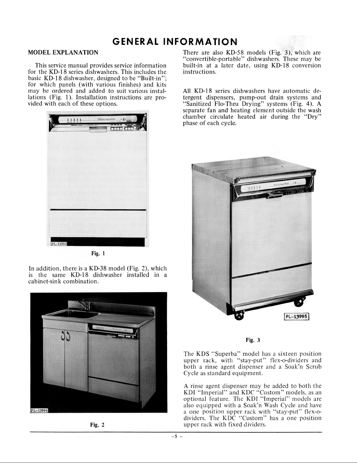
GENERAL
MODEL
This service
for
basic KD-18 dishwasher, designed
for which panels
may
lations (Fig.
vided
EXPLANATION
manual
the
KD-18 series dishwashers. This includes
be
ordered
I).
with
each
provides service
(with
various finishes)
and
added
Installation
of
these
options.
to
instructions
information
the
to
be
"Built-in";
and
kits
suit various instal-
are
pro-
INFORMATION
There
"convertible-portable"
built-in
instructions.
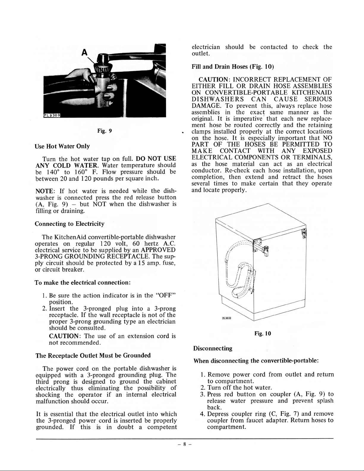
All KD-18 series dishwashers have
tergent
"Sanitized
separate
chamber
phase
are also KD-58 models (Fig.
at a later
dispensers,
Flo-
Thru
fan
and
circulate
of
each
cycle..
dishwashers. These
date,
using KD-18 conversion
pump-out
Drying"
heating
heated
element
air during
3),
which are
may
automatic
drain systems
systems (Fig. 4
outside
the
the
"Dry"
be
de-
and
).
A
wash
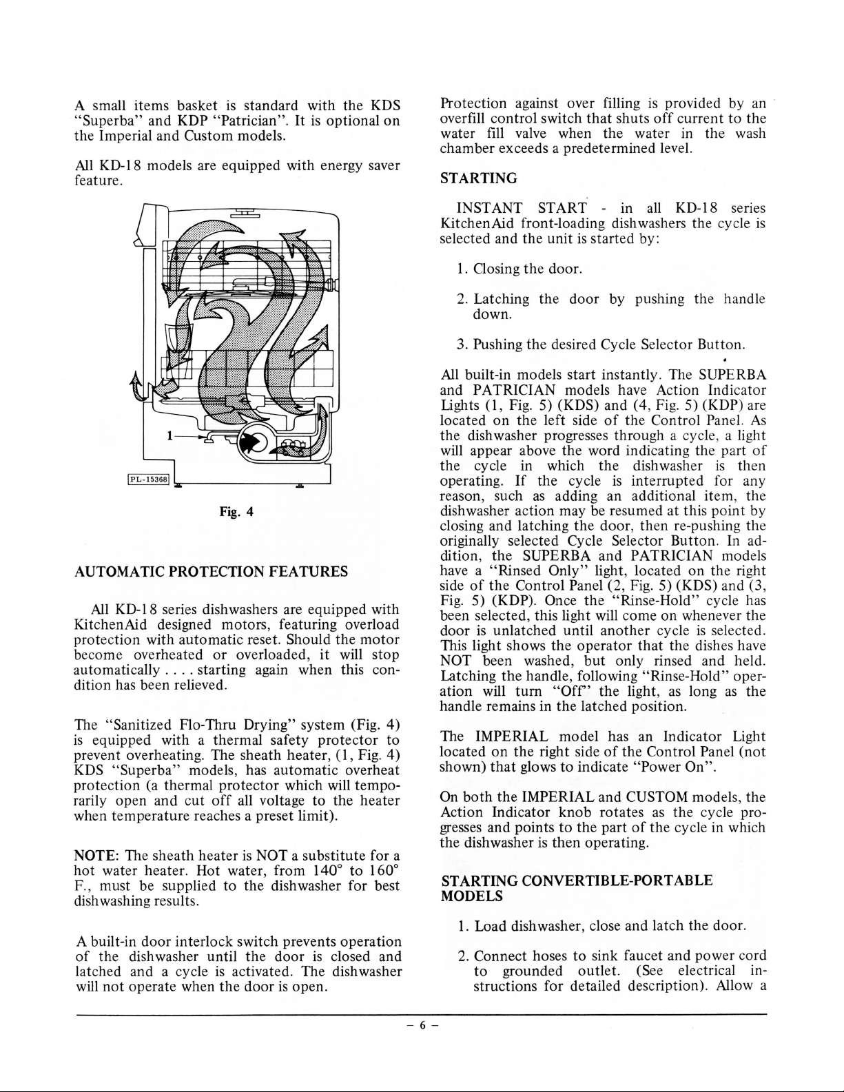
In
addition,
is
the
same
cabinet-sink
Fig.
1
there
is
a KD-38
KD-18 dishwasher installed in a
combination.
Fig. 2
model
(Fig. 2), which
Fig. 3
Th
e KDS
upp
er rack , with
both
Cycle as
A rinse agent dispenser may
KDI
optional
also
a
one
divide
upper
"Superba"
a rinse agent dispenser and a
standard
"Imperia
equipped
position
rs.
rack
l" and KDC
feature. The KDI
with a Soak'n
The
KDC
with
model
"stay-put" flex-a-divide
equipment.
"Custom"
upper
rack
"Custom"
fixed dividers.
has a
sixteen
be
added
"Imperial"
Wash Cycle
with
"stay
has a
I PL-139951
position
rs
and
Soak'n
models, as an
-put" fl
one
Scrub
to
both
the
models are
and
have
ex-a-
position
- 5 -
Page 5
A small items basket
"Superba"
the
Imperial and Custom models.
All
KD-18 models are equipped with energy saver
and KDP "Patrician".
is
standard with the KDS
It
is
optional
feature.
on
Protection against over filling
overfill control switch
that
shuts
is
provided by an ·
off
current
to
the
water fill valve when the water in the wash
chamber exceeds a predetermined level.
STARTING
INSTANT START - in all KD-18 series
KitchenAid front-loading dishwashers the cycle
selected and
1.
Oosing
the
the
unit
door.
is
started by:
is
Fig. 4
AUTOMATIC PROTECTION FEATURES
All
KD-18 series dishwashers are equipped with
KitchenAid designed motors, featuring overload
protection with
automatic
become overheated
automatically
...
. starting again when this con-
reset. Should
or
overloaded,
it
the
will
motor
stop
dition has been relieved.
The "Sanitized Flo-Thru Drying" system (Fig.
is
equipped with a thermal safety
prevent overheating. The sheath heater,
KDS
"Superba"
protection (a thermal
rarily open and
when
temperature
NOTE: The sheath
hot
water heater. Hot water, from 140°
models , has
automatic
protector
cut
off
all voltage
reaches a preset limit).
heater
is
NOT a
protector
(1,
which will
to
the
substitute
4)
to
Fig.
4)
overheat
tempo-
heater
for a
to
160°
F., must be supplied to the dishwasher for best
dish washing results.
2. Latching
the
door
by pushing the handle
down.
the
3. Pushing
All
built-in models start instantly. The SUPERB A
desired Cycle Selector Button.
and PATRICIAN models have Action Indicator
(1,
Lights
located
the dishwasher progresses through a cycl
will appear above the word indicating the part
the cycle in which
operating.
reason, such
dishwasher action may be resumed at this
closing and latching
originally selected Cycle Selector
dition,
have a "Rinsed
side
Fig. 5) (KDP). Once
been selected, this light will come
door
This light shows
NOT been washed,
Latching
ation will
handle remains in
Fig. 5) (KDS) and ( 4, Fig. 5) (KDP) are
on
the left side
If
the cycle
as
adding an additional item , the
of
the
the
door, then
the Control Panel.
dishwasher
is
interrupted
re-pushing the
Button
the
of
SUPERBA
Only"
the
Control Panel (2 , Fig. 5) (KDS) and (3,
and
PATRICIAN models
light, located
the
"Rinse-Hold" cycle has
on
is
unlatched until
the
the
handle, following "Rinse-Hold" oper-
tum
"Off'
the
another
operator
but
only rinsed and held.
the light,
cycle
that
the dishes have
as
latched position.
As
e,
a light
of
is
then
for any
point
by
. In ad-
on
the right
whenever the
is
selected.
long
as
the
The IMPERIAL model has an Indicator Light
on
the
located
shown)
On
both
that
the
right side
glows
IMPERIAL and CUSTOM models, the
Action Indicator
gresses and points
the dishwasher
is
to
knob
to
then
of
the Control Panel
indicate
rotates
the
part
operating.
"Power
of
On".
as
the
cycle pro-
the cycle in which
(not
STARTING CONVERTIBLE-PORT ABLE
MODELS
door
A built-in
of
the dishwasher until
interlock switch prevents operation
latched and a cycle
not
will
operate when
the
door
is
closed and
is
activated. The dishwasher
the
door
is
open.
l.
Load dishwasher, close and latch the door.
2. Connect hoses
to
grounded
to
sink faucet and power cord
outlet.
(See electrical in-
structions for detailed description). Allow a
-
6-
Page 6
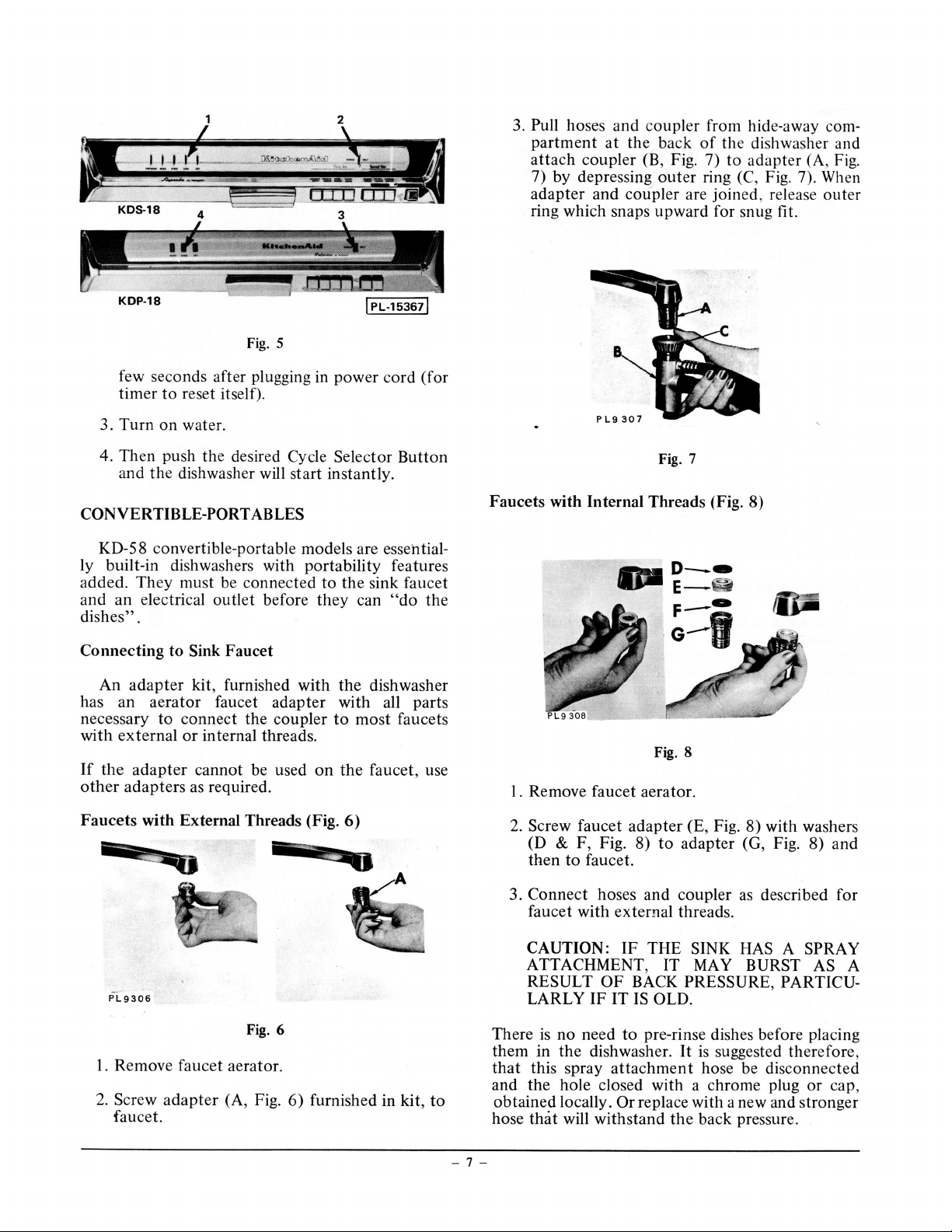
Fig.
5
few seconds after plugging in power cord (for
timer
to
reset itself).
3.
Turn
on water.
3.
Pull
hoses and coupler from hide-away com-
partment
attach
7) by depressing
adapter
at
the
back
of
the
coupler (B, Fig. 7) to
outer
adapter
ring (C, Fig. 7).
and coupler are joined, release
ring which snaps upward for snug fit.
dishwasher and
(A, Fig.
Wh
en
outer
4. Then push the desired Cycle Selector
and
the
dishwasher will start instantly.
CONVERTIBLE-PORT
ABLES
Button
KD-58 convertible-portable models are essentially built-in dishwashers with portability features
added.
and an electrical outlet before
They
must be connected
to
they
the
sink faucet
can
"do
the
dishes".
Connecting
An
has an
necessary
with
external
If
the
other
Faucets
to Sink
adapter
aerator
to
adapter
adapters
with
Faucet
kit, furnished with
faucet
connect
or
internal threads.
cannot be used
the
adapter
coupler
on
as required.
External Threads (Fig.
the
dishwasher
with all parts
to
most
faucets
the
faucet , use
6)
Faucets
with Internal Threads (Fig. 8)
I. Remove faucet aerator.
2.
Screw faucet
(D
&
then
to
3.
Connect
F, Fig. 8)
adapter
faucet.
hoses and coupler
faucet with external threads.
Fig. 7
Fig. 8
(E, Fig. 8) with washers
to
adapter
(G, Fig. 8)
as
described for
and
PL9306
Fig. 6
I. Remove faucet aerator.
2. Screw
adapter
(A, Fig.
faucet.
6)
furnished in kit,
to
- 7 -
CAUTION:
IF
THE
ATTACHMENT, IT MAY
RESULT
LARLY
There
is
them in
that
this spray
and
the
obtained
hose
that
OF
BACK
IF
IT IS OLD.
no
need
to
pre-rinse dishes before placing
the
dishwasher.
attachment
hole closed with a chrome plug
locally.
Or
replace with a new and stronger
will withstand
SINK HAS A
BURST
SPRAY
AS A
PRESSURE, PARTICU-
It
is
suggested therefore ,
hose be disconnected
or
the
back pressure.
cap,
Page 7
electrician should be contacted to check
outlet.
the
Fig. 9
Only
Water
Hot
Use
Turn the
ANY COLD
to
140°
be
and
between
NOTE:
washer
20
hot
If
connected press
is
(A, Fig. 9) -
draining.
or
filling
water tap on full.
hot
WATER. Water temperature should
F. Flow pressure should be
160°
120 pounds per square inch.
needed while
water
is
the
when the dishwasher
NOT
but
DO NOT USE
the
red release
button
Connecting to Electricity
The KitchenAid convertible-portable dishwasher
operates on regular
electrical service
3-PRONG
GROUNDING RECEPTACLE. The sup-
to
120 volt , 60
be supplied by an
ply circuit should be protected
by
hertz A.C.
APPROVED
amp. fuse,
15
a
or circuit breaker.
dish-
is
CAN
0)
REPLACEMENT
HOSE
ASSEMBLIES
OF
ABLE KITCHEN AID
CAUSE
SERIOUS
Fill and Drain Hoses (Fig. 1
CAUTION:
EITHER
CONVERTIBLE-PORT
ON
INCORRECT
FILL
OR
DRAIN
DISHWASHERS
DAMAGE. To prevent this , always replace hose
th e
assemblies in the exa
imperative· that each new replace-
is
original.
It
same manner
ct
as
ment hose be routed correctly and the retaining
the correct locations
amps installed prop erly
cl
especially important that
is
on the hose.
PART OF
MAKE
ELECTRICAL
the hose material can act
as
It
HOSES
THE
CONTACT
COMPONENTS
at
BE
WITH
NO
PERMITTED TO
ANY EXPOSED
TERMINALS ,
OR
an electrical
as
conductor. Re-check each hose installation, upon
completion , then extend and retract the hoses
they operate
several times to make certain
that
and locate properly.
To make the electrical connection:
sure the action indicator
Be
1.
in the
is
"OFF"
position.
a 3-prong
Insert the 3-pronged plug
2.
the wall receptacle
receptacle.
If
into
is
not
of
the
proper 3-prong grounding type an electrician
should be consulted.
CAUTION:
recommended.
not
The use
an extension cord
of
is
The Receptacle Outlet Must be Grounded
The
power
cord on the portable dishwasher
equipped with a 3-pronged grounding plug. The
designed to ground the cabinet
third prong
electrically thus eliminating
shocking the operator
is
possibility
the
an internal electrical
if
of
malfunction should occur.
which
It
essential
is
that
electrical
the
the 3-pronged power cord
in
is
this
grounded.
If
outlet
inserted be properly
is
doubt
into
competent
a
is
Fig.lO
Disconnecting
When disconnecting the convertible-portable:
Remove power cord from outlet and return
I.
to compartment.
water.
hot
the
Press
off
red
button
on coupler
2. Turn
3.
release water pressure and prevent splash
back.
4. Depress coupler ring (C, Fig. 7) and remove
coupler from faucet adapter. Return hoses to
compartment.
8-
-
, Fig. 9) to
(A
Page 8
GENERAL SERVICING INSTRUCTIONS
All
models
especially designed
By
removing the lower front panel, the
panel , and
are accessible
its installed position.
These instructions cover all models
series dishwashers however, all the components
of
the KD-18 series dishwashers are
to
be serviced from the front.
outer
the
control panel, practically all parts
without
moving the dishwasher from
of
the KD-18
door
that
are listed, may
model.
NOTE:
(1)
(2) NEVER reuse gaskets or sealing
or
may
not
be used for each
CAUTION : ALWAYS DISCONNECT
ELECTRICAL POWER SUPPLY
FORE
COMPONENTS.
washers.
REMOVING ELECTRICAL
BE-
- 9 -
Page 9
CYCLE
DESCRIPTION
The following cycle descriptions (KDC-18 and
KD-38
(IMPERIAL),
KDS-18, KDS-38
dishwasher) are for
All
Selection
any
heating element during the dry portion
cycle. The fan in the drying system will continue
to operate. This will reduce the
used during the cycle. Under
you may find a few drops
silverware at the end
raise the
pop out. Any time
restart an interrupted cycle, you must again push
the Energy
(CUSTOM),
KDP-18
models have the energy saver feature.
of
the Energy
of
the
"wash
door
handle, the Energy Saver
Saver
the KDI-18 and KDI-58
(PATRICIAN) and the
and
KDS-58 (SUPERBA)
the
KD-18 5eries dishwashers.
Saver
button,
and
dry"
cycles, will shut
amount
certain conditions,
of
water on dishes and
of
the cycle. Every time you
you
start a new cycle,
button
to
save energy.
model
along with
off
the
of
the
of
energy
button
will
or
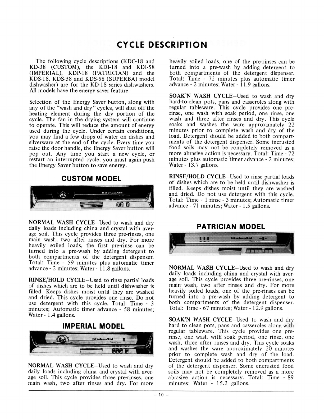
CUSTOM MODEL
heavily soiled loads, one
turned into a pre-wash by adding detergent to
both
compartments
Total: Time - 72 minutes plus automatic timer
advance- 2 minutes ; Water- 11.9 gallons.
SOAK'N
hard-to-clean pots, pans and casseroles along with
regular tableware. This cycle provides one prerinse, one wash with soak period, one rinse, one
wash and three after rinses and dry. This cycle
soaks and washes the ware approximately 22
minutes prior
load. Detergent should be added to
ments
food soils may
more abrasive action
minutes plus automatic 'timer advance - 2 minutes ;
Water- 13.7 gallons.
RINSE/HOLD CYCLE- Used
of
dishes which are to be held until dishwasher
filled. Keeps dishes moist until they are washed
and dried. Do
Total: Time - 1
advance-
WASH
of
the detergent dispenser.
71
CYCLE- Used to wash and dry
to
complete wash and dry
not
not
use detergent with this cycle .
rinse-
minutes;
of
the pre-rinses can be
of
the detergent dispenser.
of
both
compart-
Some incrusted
be completely removed
is
necessary. Total:
to rinse partial loads
3 minutes; Automatic timer
Water-
1.5 gallons.
Time-
the
as
72
is
a
NORMAL
daily loads including china and crystal with average soil. This cycle provides three pre-rinses, one
main wash, two
heavily soiled loads, the first pre-rinse can be
turned into a pre-wash by adding detergent to
both
Total: Time - 59 minutes plus automatic timer
advance- 2 minutes; Water-
RINSE/HOLD CYCLE - Used
of
dishes which are to be held
filled. Keeps dishes moist until they are washed
and dried. This cycle provides one rinse. Do
use detergent with this cycle. Total: Time - 3
minutes; Automatic timer advance - 58 minutes;
Water- 1.4 gallons.
WASH
compartments
CYCLE- Used
after
to
wash and dry
rinses and dry.
of
the detergent dispenser.
11
.8 gallons.
to rinse partial loads
up til
For
dishwasher
more
is
not
IMPERIAL MODEL
NORMAL
d
ai
ly loads including china and crystal with aver-
age
soil. This cycle provides three pre-rinses, one
main wash, two after rinses and dry.
WASH
CYCLE- Used
to wash and dry
For
more
PATRICIAN MODEL
NORMAL
daily loads including china and crystal with average
soil. This cycle provides three pre-rinses,
main wash, two after rinses and dry. For more
heavily soiled loads, one
turned
both
Total:
SOAK'N
hard to clean pots , pans and casserol
regular tableware. This cycle provides one prerinse, one wash with soak period, one rinse, one
wash, three after rinses and dr
and washes
prior to complete wash and dry
Detergent should be added to
of
the detergent dispenser.
soils may
abrasive action
minutes;
WASH
into
compartments
Time-
WASH
not
Water-
CYCLE- Used
a pre-wash by adding detergent to
67 minutes; Water- 1 2.9 gallons.
CYCLE- Used
th
e ware approximately
be completely removed
is
to wash and dry
of
the pre-rinses can be
of
the detergent dispenser .
to wash and dry
es
along with
y.
This cycle soaks
20 minutes
of
the load.
both
compartments
Some
necessary. Total: Time - 89
15.2
,gallons.
encrusted food
as
a more
one
-
10 -
Page 10
rinse partial loads
RINSE/HOLD
dishes which are
of
CYCLE- Used
be held until dishwasher
to
to
is
filled. Keeps dishes moist until they are washed
and dried. This cycle provides one rinse. Do
not
use detergent with this cycle. Total: Time - 7
minutes; Water- 2.2 gallons.
SHORT
WASH
lightly soiled loads
uystal.
and
two
wash,
right side
the
in
the detergent dispenser. Total: Time - 58
of
minutes;
Water-
CYCLE-
of
This cycle has one pre-rinse, one short
after rinses and dry.
the MAIN
of
8.4 gallons.
CANCEL/DRAIN CYCLE- Used
cycle in progress. When this
Used
glasses
plates, fine china
or
detergent only
Use
WASH
button
compartment
cancel
to
pushed, the
is
out
any
wash and dry
to
dishwasher will drain and automatically turn itself
off. To start a new cycle, wait until all indicator
lights have gone off, unlatch the door momentarily, relatch and select the desired new cycle.
be completely
If
not
of
there
timer when
the
too
is
much
The water in
drained because
the cancel
button
sump may
the
the
of
is
location
pushed .
water, lift latch, wait 3 to 5 seconds, close latch
and again press cancel /drain
button
.
approximately 46 minutes prior to a complete
the load. Detergent should be
wash and dry
added
tion
to
the detergent dispenser. A few incrusted or
of
burned on food soils may
removed
Total:
SANI
TimeCYCLE- Used
of
compartments and front indenta-
both
a more abrasive action
as
108 minutes;
Water-
when extra sanitizing
be completely
not
is
gallons.
15
necessary.
de-
is
sired. This cycle has three pre-rinses, one main
washes and
wash, three after rinses and dry.
dries daily loads with same sequence
wash cycle. In addition, the final rinse water
heated to approximately
180°
rinsing. For more heavily soiled loads, one
a pre-wash by adding
pre-rinses can be turned
both
detergent
to
into
compartments
It
the normal
as
F. before final
the
of
the detergent
of
is
dispenser. Total: Time - 67 minutes (plus time to
.5 gallons.
F.); Water-
heat water to
RINSE/HOLD
dishes which are to be held until dishwasher
of
180°
CYCLE- Used
13
rinse partial loads
to
is
filled. Keeps dishes moist until they are washed
and dried . This cycle provides one rinse. Do
use detergent with cycle. Total:
Time-
6 minutes;
not
Water- 1.5 gallons.
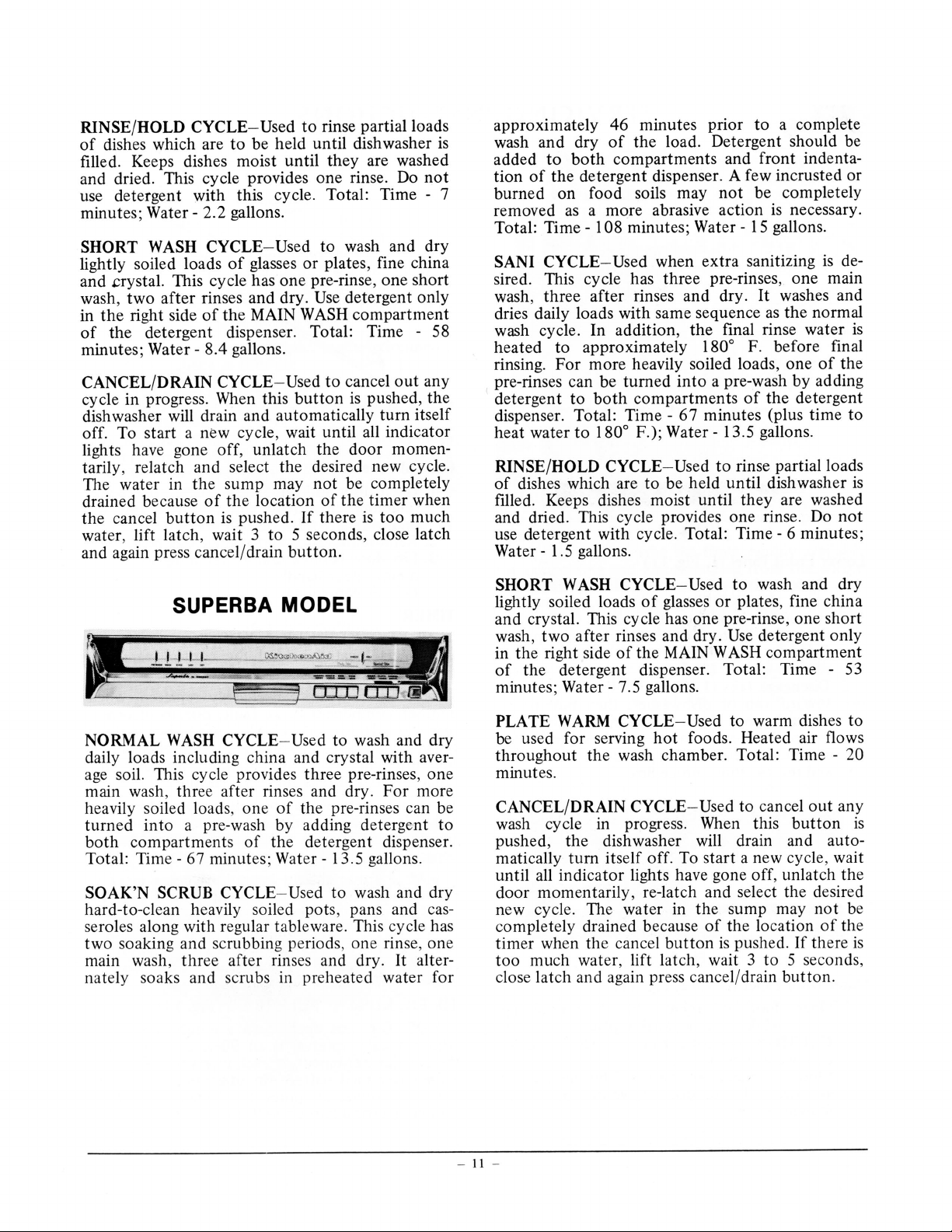
MODEL
to wash and dry
NORMAL
SUPERBA
WASH
CYCLE- Used
daily loads including china and crystal with aver-
age soil. This cycle provides three pre-rinses, one
more
after rinses and dry.
ee
main wash,
heavily soiled loa
turned
both
Total:
SOAK'N
hard-to-clean heavily
seroles along with r
soaking and scrubbing periods, one rinse, one
two
thr
, one
ds
a pre-wash by adding detergent to
into
compartments
Time-
67 minutes; Water- 13.5 gallons .
of
SCRUB CYCLE- Used
so
ular tablewa
eg
the pre-rinses can be
of
the det ergent dispenser.
to
ed pots, pans and cas-
il
re.
main wash, three after rinses and dry.
For
wash and dry
This cycle has
alter-
It
nately soaks and scrubs in preheated water for
wash and dry
SHORT
WASH
CYCLE
lightly soiled loads
of
-Used
glasses
to
plates, fine china
or
and crystal. This cycle has one pre-rinse, one short
detergent only
after rinses and dry.
wash,
in the right side
of
two
the MAIN
of
the detergent dispenser. Total: Time - 53
Use
WASH
compartment
minutes; Water- 7.5 gallons.
PLATE
WARM
be used for serving
CYCLE-Used
hot
throughout the wash chamber. Total: Time -
to warm dishes to
foods. Heated air flows
20
minutes.
any
CANCEL/DRAIN CYCLE- Used
to cancel
wash cycle in progress . When this
out
button
is
pushed, the dishwasher will drain and auto-
matically turn itself off. To start a new cycle, wait
, unlatch the
until
indicator lights have gone
all
off
door momentarily, re-latch and select the desired
be
new cycle. The water in the sump may
the location
completely drained because
timer when the cancel
much water, lift latch, wait 3 to 5 seconds,
too
of
button
pushed.
is
close lat ch and again press cancel/drain
not
there
If
button
of
the
is
.
-
11
-
Page 11
. SERVICING INSTRUCTIONS
Fig.
11
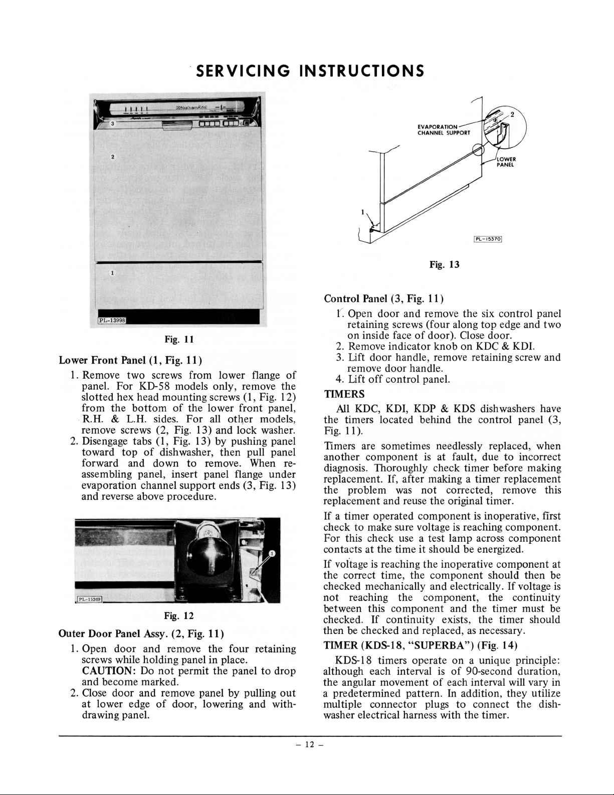
Lower
Outer Door Panel Assy. (2, Fig. 11)
Front
Panel (
I. Remove
1,
Fig.
11
)
two
screws from lower flange
panel. For KD-58 models only, remove the
slotted hex head mounting screws
from
the
R.H.
& L.H. sides.
bottom
of
the lower front panel,
For
all other models,
(I,
remove screws (2, Fig. 13) and lock washer.
2.
Disengage tabs ( 1, Fig. 13) by pushing panel
toward
forward and down
top
of
dishwasher,
then
to
remove. When reassembling panel, insert panel flange under
evaporation channel support ends (3, Fig. 13)
and reverse above procedure.
Fig. 12
1.
Open
door
and
remove the four retaining
screws while holding panel in place.
CAUTION: Do
not
permit the panel
and become marked.
2.
Close door and remove panel by pulling
at
lower edge
of
door, lowering and with-
drawing panel.
of
Fig. 12)
pull panel
to
drop
out
Fig.
13
Control Panel (3, Fig. 11)
door
( Open
retaining screws (four along
on
inside face
2.
Remove indicator knob on
3.
Lift door handle, remove retaining screw and
and remove the six control panel
top
edge and two
of
door). Close door.
KDC
& KDI.
remove door handle.
4. Lift
off
control panel.
TIMERS
All
KDC, KDI, KDP & KDS dishwashers have
the timers located behind the control panel (3,
Fig.
II).
Timers are sometimes needlessly replaced, when
another component
is
at fault, due to incorrect
diagnosis. Thoroughly check timer before making
replacement. If, after making a timer replacement
the problem
was
not
corrected, remove this
replacement and reuse the original timer.
is
If a timer operated component
check to make sure voltage
is
inoperative, first
reaching component.
For this check use a test lamp across component
contacts at the time it should be energized.
If
voftage
the correct time, the
checked mechanically and electrically.
not
between this compone
checked.
then be checked
is
reaching
reaching
If
the
inoperative component at
component
the
component, the continuity
nt
and the timer must be
should then be
If
voltage
is
continuity exists, the timer should
and
replaced ,
as
necessary.
TIMER (KDS-18, "SUPERBA") (Fig. 14)
on
KDS-18 timers operate
although each interval
the angular movement
is
of
a unique principle:
of
90-second duration,
each interval will vary in
a predetermined pattern. In addition, they utilize
multiple connector plugs to connect the dishwasher electrical harness with the timer.
-
12-
Page 12
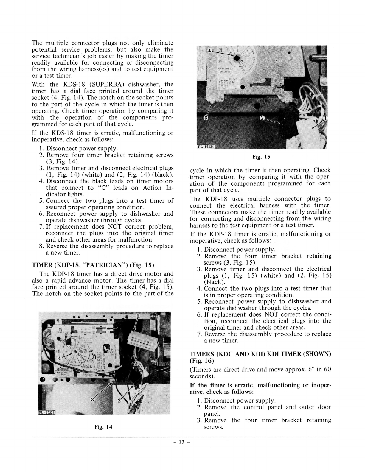
The multiple connector plugs
potential service problems,
service technician's
job
easier by making the timer
readily available for connecting
from the wiring harness(es) and
or
a test timer.
not
only eliminate
but
also make
or
disconnecting
to
test equipment
the
With the KDS-18 (SUPERBA) dishwasher, the
timer has a dial face printed around
).
The
socket ( 4, Fig. 14
to
the part
operating. Check
with
the
of
the
cycle in which the timer
timer
operation
grammed for each part
If the KDS-18 timer
inoperative, check
1.
Disconnect power supply .
as
follows:
notch
of
of
is
on
the
operation by comparing
the
components pro-
that
cycle.
erratic, malfunctioning
the
timer
socket points
is
then
it
or
2. Remove four timer bracket retaining screws
(3, Fig. 14).
3. Remove timer and disconnect electrical plugs
(1,
Fig. 14) (white) and (2, Fig. 14) (black).
on
4. Disconnect the black leads
that
connect
to
"C"
leads on Action In-
timer motors
dicator lights.
5.
Connect
the
two
plugs
into
a test timer
of
assured proper operating condition.
6.
Reconnect power supply
to
dishwasher and
operate dishwasher through cycles.
7.
If
replacement does NOT correct problem,
reconnect
and check
8.
Reverse
the
plugs
into
other
areas for malfunction.
the
disassembly procedure
the original timer
to
replace
a new timer.
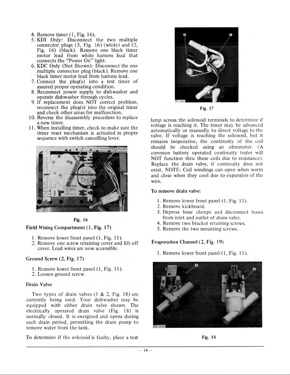
TIMER (KDP-18,
"PATRICIAN")
The KDP-18 timer has a direct drive
(Fig . 15)
motor
and
also a rapid advance motor. The timer has a dial
the
face printed around
The
notch
on
the
timer socket ( 4, Fig. 15).
socket points
to
the
part
of
the
Fig. 15
cycle in which the timer
timer operation by comparing
of
the
ation
part
of
that
components programmed for each
cycle.
The KDP-18 uses multiple connector plugs
connect
the
electrical harness with
is
then operating. Check
it
with the oper-
the
timer.
to
These connectors make the timer readily available
for connecting and disconnecting from
to
harness
If the KDP-18 timer
inoperative, check
1.
2.
the test equipment or a test timer.
is
erratic, malfunctioning
as
follows:
Disconnect power supply.
Remove the four timer bracket retaining
the
wiring
or
screws (3, Fig. 15).
3.
Remove timer and disconnect
plugs
(1
, Fig. 15) (white) and (2, Fig. 15)
the
electrical
(black).
4.
Connect
is
in proper operating condition.
5.
Reconnect power supply
operate dish washer through
If
replacement does NOT correct
6.
tion , reconnect
original timer and check
7.
Reverse
the
two plugs into a test timer
to
the
the
electrical plugs into
other
the
disassembly procedure
that
dishwasher and
cycles.
the
condi-
the
areas.
to
replace
a new timer.
Fig. 14
TIMERS (KDC AND KDI) KDI TIMER (SHOWN)
(Fig. 16)
(Timers are direct drive and move approx. 6° in 60
seconds).
If
the
timer
is
erratic, malfunctioning
ative, check
1.
Disconnect power supply.
2.
Remove
as
follows:
the
control panel and
panel.
3. Remove the four timer bracket retaining
screws.
-
13
-
or
outer
inoper-
door
Page 13
( 1, Fig. 16).
4. Remove
timer
5. KDI Only: Disconnect
connector
plugs
Fig. 16)
(3,
Fig. 16) (black) . Remove
motor
connects
6. KDC Only
multiple
black
Connect
7.
assured
Reconnect
8.
operate
If
9.
reconnect
and
10. Reverse
a
11. When installing
timer
sequence
lead from white harness lead
the
connector
timer
"Power
(Not
motor
On"
Shown): Disconnect
plug (black). Remove
lead from harness lead.
the plug(s)
proper
dishwasher
operating
power
supply
through
replacement does
plug(s)
the
areas for
other
check
disassembly
the
timer.
new
, check to make sure the
timer
reset mechanism
switch cancelling lever.
with
the
(white)
one
light.
a test
into
condition.
dishwasher a
to
cycles.
correct
NOT
the
into
malfunction.
procedure
actuated
is
multiple
two
black
timer
problem
original
to
in
and (2,
timer
that
e one
th
one
of
nd
timer
replace
proper
,
solenoid terminals
lamp across
voltage
automatically
valve.
the
reaching it.
is
voltage
If
manually
or
is
remains inoperative,
should be checked using an
common
function
NOT
Replace
battery
the
operated
thru
drain valve,
exist. NOTE: Coil windings can
and close when
they
wire.
17
Fig.
timer
e
Th
to
reaching
continuity
e
th
continuity
these coils
co
if
due
cool
determ
to
may be advanced
voltage
ect
dir
solenoid,
the
th
of
ohmmeter.
tester
resistance).
to
due
ntinuity
open
expansion
to
do
when warm
in
to
but
e co
es
of
e if
the
it
il
(A
will
not
th e
Field Wiring
Remove lower
1.
2. Remove
Compartment
front
screw retaining cover and
one
cover. Lead wires are
Ground
Screw (2, Fig. 17)
1. Remove lower
front
2. Loosen ground screw.
Drain Valve
drain valves ( l
of
types
Two
ly being used. Your
ent
urr
c
equipped with e
electrically
normally closed.
each drain period ,
remove water from
ith
operated
It
permitting
th
Fig. 16
( 1, Fig. 17)
panel
now
panel ( l , Fig.
dishwasher
n valve shown. Th e
ai
er dr
valve (Fig. 18)
in
dra
energized and
is
e tank.
ll
Fig.
(1 ,
accessible.
11
Fig. 18) are
2,
&
opens
drain
the
).
lift
).
may
during
pump
off
be
is
to
remove drain valve:
To
).
11
Fig.
,
(I
panel
Remove lower
l.
front
2. Remov e kickboard.
3. Depress hose clamps and disconnect hoses
drain valve.
from inlet and
4. Remove
Remove
5.
outlet
bracket retaining screws.
two
two
the
of
mounting
screws.
Evaporation Channel (2, Fig. 19)
Remove lower
1.
panel ( l, Fig.
front
II).
determine
To
if
th
e solenoid
faulty, place a test
is
Fig. 18
-
14
-
Page 14

2. Remove
end)
(3, Fig. 19).
3. Straighten
of
channel. Remove
two
retaining screws
conduit
tabs
(1
,
Fig. 19) in
evaporation
(one
at
channel.
each
center
NOTE: Wiring harness is sealed
conduit
Door
Springs
I. Make sure
2. Grasp
lift spring
3.
Adjustment
spring
the
and
must be pulled free.
( 4, Fig. 19)
power
top
hook
mounting
is
turned
portion
of
off
door
is
provided by changing
bracket
vertical frame member.
to
channe
OFF.
spring ( 4, Fig. 19)
stop
bracket.
(Fig.
20)
loc
ation
and
door
on
l
JPL-140061
DOOR
SPRING BRACKET
Fig.
20
between
the
closed.
the
certain it
the
timer
overfill
If
contro
the
solenoid
filter screen
is
not
and
fill valve
must
l switch, which
is
functioning
shou
ld
be removed
clogged. If th e
pass
through
is
normally
as it should,
to
va
lv
e still mal-
make
functions, it should be replaced.
To
replace fill valve:
1.
Shut
off
water
supp
ly valve.
2.
Remove low
3. Disconnect
4. Remove two
5. Disconnect electrical leads at valve coil
er
front
water
bracket
panel
inlet line
mounting
(I,
Fig.
at
fill valve.
11
).
screws.
(or
coils).
6. Depress hose clamp
and
disconnect fill line
hose.
Fig
Kickplate
The
kickplate
Fill Valve (Fig.
Two
Fig.
out
l
et
If
water
the
kickplate
sty
21)
(2, Fig.
is
fill
up
(for
period,
Adjustment
can
or
down.
21)
les
of
fill valves, single coil
convertible-portable)
21)
(for
not
passing
first
reaching each solenoid
operative.
viously
The
outlined
solenoid
under
. 19
be
adjusted
and
KD-18) are used.
through
make
and
the
certain voltage
that
may
be
"Drain
fill valve during
the
checked
Valve".
by
moving
outlet
dual coil
solenoid
as pre-
Voltage
(1,
is
is
CAUTION:
PARTS
ANY WAY
-
15
-
THE
SHOULD
OR
PARTS SUBSTITUTED.
VALVE,
NEVER
Fig
.
21
OR
COMPONENT
BE
ALTERED
IN
Page 15

4. Remove standpipe ( 4, Fig. 23) and gasket (3,
Fig. 23) from beneath tank.
5.
When reassembling standpipe, make sure
gasket
is
on stem before inserting stem
through the tank.
6. Using a tool, securely tighten standpipe
(2, Fig. 23
).
nut
Thermostat and Thermal Protector (KDS Only)
& 2, Fig. 24)
(1,
A thermostat
the water heater during the Sani Cycle.
the timer
motor
Fig. 24) (KDS only) controls
It
holds
circuit open (preventing timer
advancement) until the water reaches approximately 180° F.
closes, allowing the timer
at
which time the thermostat
to
advance.
(I
Fig. 22
Overfill Control Switch ( 1, Fig. 22)
The normally closed overfill control switch
is
an
electrically operated safety device in series with
the fill valve. This safety device will operate only
the timer stalls during fill cycle
washer fails to drain.
It
will
valve against a malfunction caused
material
or
a mechanical failure.
Excessive water in tank (approx.
of
hydro sweep) actuates the overfill control
not
or
if
protect
by
1/4"
below
the dish-
if
the fill
foreign
hub
switch, opening fill valve circuit.
is
This switch
permanently factory adjusted and
has automatic reset. DO NOT ATTEMPT TO
ADJUST.
To disassemble from dishwasher:
I.
Remove lower front panel
2.
Remove staple from cover.
(I,
Fig.
II)
.
3. Open cover and remove retaining screw.
4. Disconnect electrical lead wires to switch.
The automatic thermal
protector
normally closed safety device.
(2, Fig. 24)
If
for any reason
is
the sump temperature exceeds approximately
200° F. the
current flow
does
not
protector
to
the 1400 watt water heater.
contacts open , stopping
interrupt dishwasher cycle.
It
will auto-
It
matically reset at approx. 150° F.
To Service:
I.
Remove lower front panel
(l,
Fig.
II).
2. Remove thermostat cover.
3. Disassemble thermostat and thermal protector
by
rotating them
out
of
mounting
spring (3, Fig. 24).
a
Overfill Protection
Float
Standpipe (Fig. 23)
Should the tank reach an excessive level
(approx . 14 quarts), the overflow protection float
will prevent flooding by shutting
The float
is
located inside the left front
off
the fill valve.
comer
of
the tank.
To dissassemble from dishwasher:
I. Remove lower front panel ( 1, Fig.
2. Remove overfill control float
3.
Remove standpipe
nut
(2, Fig. 23) from
(I,
Fig. 23).
11
).
inside tank.
Fig. 23
-16-
Page 16
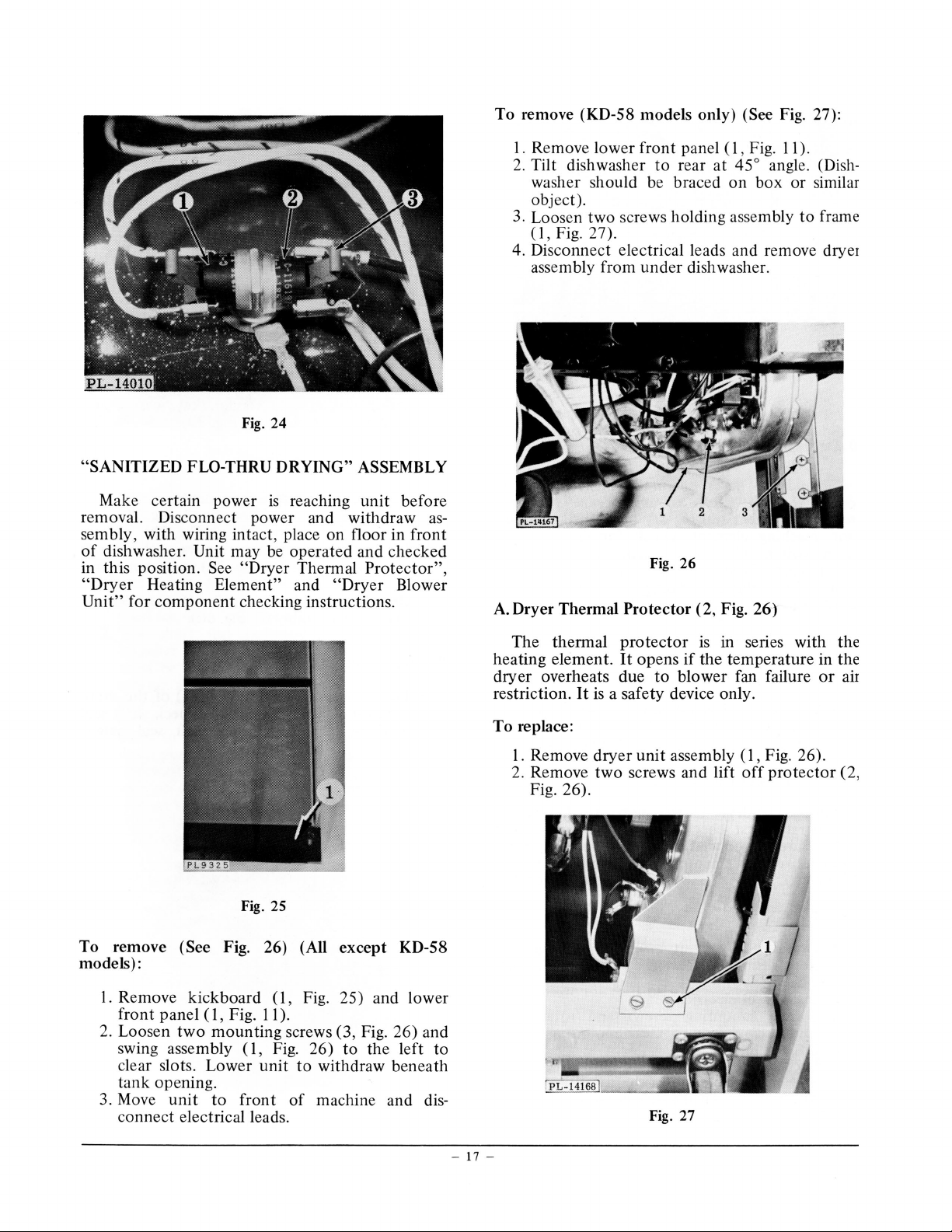
Fig. 24
"SANITIZED FLO-THRU DRYING" ASSEMBLY
To remove (KD-58 models only) (See
I. Remove lower front pan el ( 1, Fig.
2.
Tilt dishwasher
to
rear at 45° angle. (Dish-
Fig.
11
27):
).
washer should be braced on box or similar
object).
3.
Loosen two screws holding assembly to frame
(1,
Fig. 27).
4. Disconnect electrical leads and remove dryer
assembly from under dishwasher.
Make certain power
remova
l.
Disconnect power and withdraw
is
reaching unit before
assembly, with wiring intact, place on floor in front
of
dishwasher. Unit may
in this position.
"Dryer
Unit"
Heating Element" and
for component checking instructions.
See
be
operated and checked
"Dryer Thermal
"Dryer
Fig. 25
Protector"
Blower
To remove (See Fig. 26) (All except KD-58
models):
,
A.
Dryer Thermal Protector (2, Fig. 26)
The thermal
heating element.
dryer overheats due
It
restriction.
To
replace:
1.
Remove dryer
2.
Remove two screws and lift
is
Fig. 26
protector
It
opens
is
in series with the
if
the temperature in the
to
blower fan failure
a safety device only.
unit
assembly
(1,
off
or
Fig. 26).
protector
air
(2,
Fig. 26).
I. Remove kick board ( 1, Fig. 25) and lower
(1,
Fig.
11
front panel
2.
Loosen
two
mounting screws (3, Fig. 26) and
swing assembly
clear slots. Lower unit
).
(1 , Fig. 26)
to
withdraw beneath
to
the left
to
tank opening.
3. Move
unit
to
front
of
machine and dis-
connect electrical leads.
Fig. 27
- 17 -
Page 17

Fig. 28
B.
Dryer Heating Element (5, Fig. 28)
Should the dryer heating element become inoperative first check to make sure voltage
reaching element (during dry period).
not
reaching element, check for faulty energy
saver switch.
(thru thermal
If
voltage
protector)
is
reaching the element
(4, Fig. 28) next check
continuity using an ohmmeter.
If
voltage
If
no continuity
exists, replace element.
To replace:
I.
Remove dryer unit assembly (1 , Fig. 26).
2.
Disconnect electrical leads.
3. Remove the two retaining screws and lift
dryer heating element (5, Fig. 28).
4. Replace element and reassemble dryer unit.
is
is
out
WASH
PUMP, DRAIN PUMP AND MOTOR
SHAFT SEAL REPLACEMENT.
It
is
not
necessary
the dish washer
pump
or
motor
Wash
Pump (Figs. 29 & 30)
1.
Remove lower rack.
2.
Lift up and remove 4-Way Hydro Sweep
shaft seal.
to
remove the
to
install the wash pump, drain
motor
(wash arm).
3. Lift up and remove strainer.
4. Remove four retaining screws and lift
wash arm support
5.
Remove wash pump impeller retaining screw,
(1
, Fig. 29).
spring washer, cap washer, key washer and
wash pump impeller (2, Fig. 29).
Drain Pump (Figs. 29
1.
Remove wash pump components.
2.
Remove lower pump housing (3, Fig. 29).
3. Remove fine strainer seat
& 30)
(1
, Fig. 30).
4. Remove four retaining screws and lift
drain inlet cover (
top
(5, Fig. 29).
5.
Remove drain pump impeller (6, Fig. 29) and
4,
Fig. 29) and drain pump
shaft seal assembly (2, Fig. 30).
Pump and Shaft Seal Installation
1.
Proper spacing (working height)
pump impeller
is
important. Check shaft seal
of
working height with the shaft seal height
from
off
off
the drain
C.
Dryer Blower Unit ( 1 & 3 Fig. 28)
Should the dryer blower
to
operate , first check
make sure
inoperative, check
motor
shaft is free.
motor
ohmmeter. Replace
motor
the
winding continuity with
motor
if
(3, Fig. 28) fail
voltage supply. Next
If
motor
remains
tests prove negative.
To replace:
1.
Remove dryer unit assembly
(1,
Fig. 26) .
Note terminal location and replace in same
location.
2.
Disconnect electrical leads.
3. Loosen mounting screws and rotate unit
counterclockwise to clear mounting screws.
Lift
out
blower unit.
4. Loosen set screw and pull blower fan wheel
1,
Fig. 28) from
(
motor
shaft.
5. At reassembly, make sure dryer blower
cover (2, Fig. 28)
is
in place.
motor
Fig. 29
- 18 -
Page 18

Fig. 30
"touch"
31
).
to
Use the proper combination
on
dimension.
smaller I.D. and are
Limits
touch
top
or
and
of
"clear"
of
the
gauge (TL-91 043) (
the seal height gauge are
.631"
motor
to
clear. (See Fig.
of
shim washers
shaft to attain proper
NOTE: These shim washers have
NOT
the same washers
used for wash impeller spacing.
2.
The shaft seal assembly and drain
impeller are furnished
must be replaced
as
attemp a partial replacement. Use
as
a lubricant for assembling seal. Moisten the
as
a single unit and
a single unit only. Do
water only
bellows seal (stationary part) and press into
place in the drain housing cavity. Install the
drain pump impeller and rotating assembly a
the way down over the
motor
shaft. Make
sure no washers have stuck to the underneath
side
of
the impeller and the stationary part
completely seated in the drain pump body
for proper alignment. Firmly seat
Fig.
31
"0"
1,
Fig.
.606"
31
).
pump
not
ll
is
ring
around shaft into groove
of
drain pump
impeller.
3. Place
the drain pump top (stainless ste
el
soft
waste disposer) (5, Fig. 29) and inlet cover
( 4, Fig. 29)
into
position and securely fasten
with the four retaining screws.
4.
Position
upper spray supply hole
the lower pump housing
is
directly above the
so
the
rubber overhead connector. The recesses in
the lower pump housing must be in alignment
with the
the drain housing.
bearing spacers
32) furnished in the kit on top
motor
mounting plate bosses over
NOTE:
(Part
Assemble the four
No.
A-1
02652)
of
(1,
the lower
Fig.
pump housing with four retaining screws
removed in disassembling the wash arm
support.
5.
Assemble wash pump impeller making sure it
engages the drain pump impeller. Assemble
spring washer, cap washe
r,
key washer, and
retaining screw in proper sequence and
tighten screw.
NOTE: Check wash pump
impeller spacing with shim gauge (TL-91 042)
(2, Fig. 32) beneath vane
Fig. 32
impeller. The longest section
gauge should clear. The combination
sections (together) should
of
the
shim gauge are .0 15"
.025"
tion
to
"touch".
of
shim washers
Add the proper combina-
to
of
just
to
the top
wash
of
pump
the shim
of
both
touch. Limits
"clear"
of
and
the drain
impeller to attain the proper dimension.
Always use at least one shim washer.
6. After spacing wash pump impeller correctly,
remove the four bearing spacers.
7.
Install ring gasket to the lower pump housing.
Seat gasket properly. Make sure it
is
not
twisted in the groove.
8. Install the wash arm support and position it
with the word
dish washer with the four retaining scre
"FRONT"
to the front
of
the
ws.
Reassemble fine strainer seat, strainer, lower
-
19
-
Page 19

Fig. 33
wash arm, and lower rack in their correct
location. Check dishwasher for operation.
Motor ( 4, Fig. 32)
rotates
It
motor
The 1/2
operates
R.P.M.,
3450
H.P.,
wash and drain pumps.
both
single phase
counterclockwise, incorporates a centrifugal start
and integral
switch, ball bearing
mounted
rotor
automatic overload protector.
and
or
motor
pump
pry between gasket and tank
not
may be damaged.
p~t.
Pry to loosen
6. Withdraw complete
motor
from inside wash tank.
To reinstall
Motor and
I.
"arrow"
word
positioned to the front
Install
2.
motor:
pump
on
"FRONT"
motor
and
ed with
unit must be insta
motor
mounting plate and
ll
centered in the tank and
the dishwasher.
of
a complete
as
pump
unit
assembly from inside the tank.
Moisten the complete surface
3.
of
mounting plate gasket (7, Fig. 29) and area
inside tank where gasket fits with water to
aid installation.
4. Apply downward pressure on wash arm supsnap gasket in place in tank sump .
to
port
5. Make sure
motor
mounting plate ga
sk
Fig. 32) seals the tank.
enamel
from
.
unit
motor
et (3,
Always check
other
Check
components, before making replacement.
motor
motor
shaft
rotate. Apply 115
motor
white leads.
sources
other
If
trouble .
of
operation, independent
make certain
to
V.A.C.
across the black and the
it
starts and runs , check for
is
free
To remove:
Remove lower front panel and kickboard.
1.
Disconnect
2.
motor
electrical leads.
3. Remove drain and upper spray tubes from
motor
4. Unsnap and remove the three
mounting plate.
motor
retaining
clips.
Remove fine strainer seat from inside tank.
5.
Insert a screwdriver blade between
mounting plate and gasket. CAUTION: Do
of
to
motor
Fig. 35
6. Seat the fine strainer.
Install the three
7.
motor
retaining clips and
snap them in place.
flexible
motor
to
mounting
8. Connect
upper
spray supply tube
connector and drain tube to
plate and tighten. Make sure the drain hose
kinked.
not
9. Connect the
motor
electrical leads.
10. Check for leaks.
11. Assemble kickboard and lower front panel.
Constant Wash/Rinse System (Fig.
33)
is
Fig. 34
-
20 -
Remove the three nuts
I.
spray
upper
the
Remove
2.
upper
tube (3, Fig.
System (Fig. 34)
Remove
I.
Wash
two
Middle
that
(2, Fig. 33 ).
unit
,
(1
Fig. 33)
spray manifold from supply
.
33)
Fig. 34) and strap (2,
,
screws
(1
retain
Page 20

Fig. 36
Fig. 34)
that
holds the manifold to upper
rack.
2. Unsnap the four clips (4 , Fig. 34) and remove
middle wash arm guard (3, Fig. 34).
3. Pull complete assembly including manifold
tube (6, Fig. 34) from middle wash arm
receiver (5, Fig. 34).
Sheath Heater (1, Fig.
35)
(KDS Only)
To Replace:
1.
Remove lower front panel and kickboard.
2.
Disconnect electrical lead wires.
3.
Remove
from heating element
NOTE:
Always reassemble washer
4.
Lift and remove heating element from inside
of
tank.
Self-Cleaning Filter (Fig.
1.
Remove lower wash arm.
2.
Lift
3. Squeeze center section (2, Fig.
the
two
hex nuts and ring gaskets
on
underside
Use
new ring gaskets at reassembly.
and
ground lug!
36)
out
fine strainer assy. (1 , Fig. 36).
36)
of
of
strainer together and lift out.
4. Grasp rear and front
(1,
Fig. 30), lift up
out
.
Air Gap
& Fill Tube
The fill line air gap
of
tank. Do
dishwasher
not
is
removed. (Nut must be securely
tightened). · Tube must
gap
junction)
or
at fill valve.
Wiring Harness (KDP
1.
Remove
outer
tab
of
fine strainer seat
on
rear
tab
first, then lift
(1
& 2, Fig.
is
not
loosen
not
& KDS)
37)
accessible from inside
nut
at inlet unless
be kinked at
top
door panel, control panel and
lower front panel.
2. Remove
3.
Remove evaporation channel.
door
vapor shield.
4. Remove program switch bracket.
tank
coarse
(air
5.
Remove timer.
6.
Disconnect leads in door
lights, all switches, dispensers, door frame
ground, rinse agent dispenser ground, and
multiple connector plugs (one white (3, Fig.
38) and one black (4, Fig. 38)). On KDS and
KDP, also disconnect lead to rinse-only light.
7.
Disconnect all nonwhite leads to blower
motor
motor
also disconnect nonwhite leads
thermostat and sheath heater.
NOTE: Following removal
wiring harness, some electrical connections
still remain , such
fill valve, dryer heater and fan assembly
connections, fill valve connection. On the
KDS, there are also connections
thermal protector.
Wiring Harness (KDI
1.
Remove
lower front panel.
2. Remove door vapor shield.
3.
Remove evaporation channel.
4. Remove program switch bracket.
5. Remove timer .
6.
Disconnect leads in door
(KDI only), dispensers, and plug (KDC only) ,
or
door frame ground.
7.
.
Disconnect all nonwhite leads to blower
motor, heater thermostat, overfill control
switch, drain valve,
fill valve.
to
action indicator
, overfill control switch, drain valve,
and white lead
to
fill valve. On KDS,
to
of
the complete
as:
overfill control switch to
to
the
& KDC)
outer
door panel, control panel, and
to
switches, light
multiple plugs (KDI only)
motor
1
2
Fig. 37
to
timer and
and white lead to
heater
:#:87
-
21
-
Page 21

Fig. 38
Indicator Sequence Light Assy. (KDS & KDP) (3,
Fig. 40)
1.
Remove control panel.
2.
Remove indicating sequence light assembly
and disconnect leads.
1. Remove
2. Remove four retaining screws (with shim
outer
door panel and control panel.
washers when required).
NOTE: When replacing a door latch, program
switch
program switch cancel spring (
door handle latched and the normal cycle
depressed, check for correct clearance. The clea
ance between one side
switch cancel lever cap should be
(Fig. 38) with the
or
inner door panel , ALWAYS check the
1, Fig. 3 8). With th e
of
the cancel spring and the
1 /3
2"
to 3/3
other
side
of
the cancel spring
button
r-
2"
just contacting the program switch cancel bar. The
program switch cancel spring
is
removable for
adjustment by unsnapping it from the riveted
anchor. Pull
on tab
(1,
Fig. 39) with needle
out
nose pliers to disengage tab from detent, then pull
straight forward (see Fig. 39).
Door Latch Mechanism (2, Fig. 38)
is
The latch
actuates
the
a safety device
program push
each time the door handle
operates
the
interval timer line switch on KDC and
that
button
is
unlatched.
automatically
cancelling lever
It
also
KDI models and resets the timer.
The latch can be adjusted
to
increase the door seal
tension by adding shims between latch and inner
door mounting bracket.
Fig.
40
Program Switch Assy.
1.
Remove control panel and
2.
Remove switch bracket retaining screws,
(1,
Fig. 40) (KDS shown)
outer
grounding clip, lock washer and disconnect
electrical leads.
3.
Lift
switch assembly clear
reassembly be sure
to
reinstall grounding clip
of
and lock washer.
NOTE: Interlock switch (2 , Fig. 40)
accessible when control panel
is
removed.
door
door. At
panel.
is
also
Fig. 39
Inner Door Assy. (Fig. 40)
1.
Disconnect power supply.
2. Remove
panel.
-22
-
outer
door
panel and lower front
Page 22

3. Remove retaining screws and lift
off
vapor shield.
4. Unhook
5. Pull
door
springs.
off
action indicator
knob
(KDI
6. Remove control panel.
7.
Remove retaining screws from program
switch and bracket assembly.
8. Disconnect electrical wiring harness.
9. Remove timer.
I
0.
Disconnect electrical leads
dispenser
and
detergent dispenser.
11. Remove clips, push
at a
90°
angle and withdraw from hinges.
out
at
rinse agent
pins and lift
&
off
door
KDC).
door
Rinse Agent Dispenser (4, Fig. 40) (Optional
KDI
&
KDC)
on
Check by applying voltage to the dishwasher
and advancing timer thru two
or
three cycles;
observe rinse agent liquid on inner door assembly.
1. Remove
2.
Disconnect electrical lead wires.
3. Open
Lift
NOTE:
outer
door panel.
door
off
dispenser.
and remove
two
retaining nuts.
Avoid spilling concentrated rinse
agent liquid on counter top, floors, etc.
Fig.
41
Fig. 42
NOTE:
At reassembly use new detergent
dispenser gasket.
Upper Rack Track ( 2, Fig. 41)
1.
Pull
track forward to bumper stop. Lift tab
from detent hole and remove stop retaining
stud
(1,
Fig.
41
).
2. Pull track forward, releasing bumper. Withdraw track.
3.
Use
shim washers behind rollers for align-
ment, when required.
Door
Seal Gasket (1, Fig. 42)
The
door
seal
is
one piece wire
furnished
rod
in place. Retaining clips are
as
an assembly with a
included.
1.
Starting
clips from the
at
the
bottom,
tank
pry the seal retaining
by inserting a screwdriver
blade between wire rod and seal.
2.
Install the seal, starting at the top and
snapping new clips
into
holes in the tank.
Never reuse old clips.
3. Run dishwasher through a cycle and check
for leaks.
Detergent Dispenser (5, Fig.
CAUTION:
potential at
1.
Remove
2.
Disconnect electrical lead wires.
Bimetal units have voltage
all
times when
outer
door panel.
40)
motor
is
operating.
3. Remove bimetal and holder assembly (6, Fig.
40).
4. Remove retaining screws.
5.
Open
door
and lift out dispenser assembly.
6.
Reassemble bimetal unit
1/64"
clearance from stop on swing arm.
to
just
touch
or have
Lower Door Baffle
1.
Remove
2. Remove
3. Pull
4. Unhook
5. Remove hinge pin retaining clips and hinge
pins.
6. Lift
7. Remove three retaining screws holding lower
baffle
NOTE:
edges with
-
23
-
outer
door
panel.
door
vapor shield.
wiring harness from
door
springs.
off
door.
(I
, Fig. 43) to lower edge
When replacing
putty
to
prevent leaks.
slots
in the door.
door
of
the door.
baffle, seal
Page 23

5.
Remove tank seal (2, Fig. 43) by pulling on
end.
6. To reassemble tank seal, insert
se
al at one end
and pull it through.
DRAINING CONVERTIBLE-PORT ABLE
DISHWASHERS
Fig. 43
Tank Seal Assembly
I. Remove
2.
Remove hinge pin retaining clips and hinge
outer
door
panel.
pins.
3. Unhook
4. Lift
off
door
door.
springs.
Drain dish washer hoses before
serv1cmg
any
component which requires placing dishwasher on
its back
count
or
when making conversion to under-the-
er installation. Remove lower rack, wash arm
and strainer.
I.
Tilt dishwasher
to
rear at 45° angle.
(Diswasher should be braced on box or
similar object).
2.
Remove lower front panel.
Fig. 45
Fig. 44
3. Place suitable container under hose connections
(both
fill and drain hoses) at the fill
and drain valves.
4. Disconnect hoses from fill and drain valves.
5. Drain hoses
into
container.
Electrical Cord with Reel (KDI-58
Only) (2, Fig. 44)
To remove power cord with reel:
I.
Remove two mounting screws
from power cord housing.
2.
Remove power cord housing
push through slot opening, provided
housing.
3. With unit drained, lower rack, wash arm and
strainer removed, place dishwasher on back.
Protect fmish by laying it
object.
4. Remove lower front panel.
5. Disconnect electrical leads from reel.
6. Remove one mounting screw
slide cord reel
-
24-
to
the right and lift out.
& KDS-58
(1,
Fig. 45)
(I,
Fig. 46) and
on
a rug or similar
(1,
Fig. 44) and
in
the
Page 24

reassemble cord reel
To
KDS-58 Only)
dishwasher (KDI-58
on
&
1 2
/
__
Replace reel
1.
Fig.
(I,
screw
Extend
2.
corner
Pull
3.
corner
cord
mounting
Using
4.
reconnect
5. Make sure
Replace lower panel.
6.
power
dishwasher cabinet .
of
power
housing. Install cord housing with two
cord
cabinet. Replace cord in power
of
screws
nuts
wire
ground
there
frame with one
on
44).
cord up through left rear
through
(1 ,
connect
lead.
proper tension on the reel.
is
opening in top left
45).
Fig.
electrical leads and
mounting
I
I
PL-141281
\,
I
--
47
Fig.
WATER
(Fig. 48)
To
1.
2.
3. Remove hose clamp bracket (2, Fig. 48)
(FILL
remove:
See
PORTABLE DISHWASHER".
Remove anchor bracket (3, Fig.
guard ( 4, Fig. 48).
holding hoses
AND DRAIN) CONNECTIONS
"DRAINING
frame.
to
CONVERTIBLE
48)
and
-
ho~e
Fig. 46
Electrical
I. Remove
2. Remove
3. Locate
4. Disconnect
reassemble, reverse removal procedure
To
Power
from
from
cord housing slot.
washer
screw.
one
frame ground.
NOTE: Make sure
positioned in
and harness wire does
operation.
Cord (KDC-58)
two
housing.
cord
power
cabinet
cord
disassemble clamp by removing
and
power
mounting
cord housing
push end
and
clamp
cabinet
at
cord
power
for ease
not
screws (2, Fig. 4 7)
top
electrical leads and
interfere with cord
47)
Fig.
(1,
through
cord
of
dish-
corner
cord is properly
of
operation
of
Fig. 48
- 25 -
Page 25

4.
Stand
dishwasher upright and pull hoses
through hose coupler housing in top, right
dishwasher.
of
rear
To reassemble, reverse above procedures
NOTE:
especially careful
Be
that
dressed properly in loop in cabinet and
touch electrical components
hoses do
terminals,
not
hoses may
as
conductors under
as
act
some conditions.
hoses are
that
or
CONVERSION OF
Conversion
models
of
undercounter
to
KD-58
the KD-58 Convertible-Portable
MODELS
installation requires
special instructions. Complete instructions for
conversion and the undercounter
both
the
installation are provided.
REMOVAL OF TOP (Fig.
I. Remove retaining screws
49)
Fig. 49) from
(I,
49
Fig.
top anchor mounting brackets and front
wraparound housing.
2. Remove upper retaining screws
(I,
from hose coupler housing.
forward and lift off.
3. Slide
top
of
Fig. 48)
-
26
-
Page 26

CONDITION
SERVICE
POSSIBLE CAUSE
TIPS
REMEDY
Upper Rack binds.
Visible water vapor exhausting
from
under
door
N
__,
("steam").
1.
Binding due
not
center.
2. Binding
forced
3. Binding
tween
4. Binding
to
user's pushing from side,
due
to distortion. (Has been
out
of
shape).
due
to
distortion. (Distance be-
upper
rack rollers changed).
due to
improper distance be-
tween upp er rack track roller screws.
1.
High relative humidity
and/or
cool
room
temperature (air conditioning, etc.).
2.
Excessive water supply temperature.
3. Dishwasher installed against outside co
ld
wall.
1.1
Push from
center
. (Rack flexible for
user's convenience in use/loading).
2.1
Align rack wheels
each side (by eye). U
into
same plane
se
hands (rack
flexible).
3.1
Stretch
dimension 20
of
4.1
Add
or squeeze rack to make
-5/8" (over outside edge
rollers).
or
remove spacers to align tracks
and remove distortions:
a.
There should always be one LESS
spacer
than
differ depending
on
the rear track roller screws
on
the front. Actual numbers
on
production
tion.
Some visible water vapor
1.1
bri
ef
time - no correction required or
possibl
1.
2
Change room conditions as necessary
e.
(decrease humidity
is
and/or
room temperature).
1.3
Make certain
l
et
does
room
not
blow directly
air conditioner
dishwasher.
2.
1
Lower water temperature as necessary
but
not
below 140° F. at dishwasher.
3.1
Insulate dishwasher from co
on
loca-
normal for
increase
onto
face
ld, as
required.
is
out
of
-
I
i
4-Way Hydro Sweep
does
not
turn
at proper
speed. (30- 43
RPM
speed for wash arm
operating
in
clean/clear water).
1. Not
enough water.
2. Worn wash arm.
3. Strainer clogged.
Hydr
4. 4-Way
5.
Too
much suds.
o Sweep nozzles clogged.
1.1
See " Insufficient fill
not
remain in
2.
1
Replace Hydro Sweep wash arm
and/or
Clean strainer and strainer cleaning nozzle.
3.1
4.1
Clean nozzles.
Correct the
5.1
support.
amoun
" and "Water does
tank".
t and
type
of
or try different brand using varying
amounts.
deterg
ent
Page 27

Water does
tank.
CONDITION
remain in
not
SERVICE TIPS
POSSIBLE CAUSE
Foreign
1.
Faulty drain valve spring.
2.
matter
on seat
3. Drain valve inoperative.
4. Timer malfunctioning.
drain valve.
of
(C
REMEDY
Remove foreign matter.
1.1
2.1 Replace drain valve.
3.1 Replace drain valve.
4.1 Replace timer.
Water on floor after fill
cycle.
I
Leaks water at the motor.
Excessive noise
or
during drying cycle.
dry.
Dishes do
00
"'
not
vibration
Water inlet tube damaged during
1.
installation.
air gap clogged with foreign
Fill tube
2.
of
matter.
air gap (rare).
3. Water
Shaft seal leaking.
1.
Fan
1.
Heater fan
2.
3. Shaft
Water
1.
2.
3.
4. Dryer thermal
"splashing-out"
loose on shaft .
of
out
fan motor.
on
bent
enough.
hot
not
Dryer heater element burned
Fan
motor
inoperative.
protector
of
balance.
.
out
inoperative.
5. Erratic timer operation.
Energy saver mechanism malfunctioning.
6.
Air inlet check valve assy. stuck.
7.
(If
dishwasher equipped with check valve).
8. Blower Fan improperly positioned
on shaft.
Replace water inlet tube
1.1
necessary.
as
2.1
Clean fill tube.
3.1
Replace air gap.
1.1
Replace
Remove and re-tighten fan.
1.1
Replace fan.
2.1
motor
shaft seal.
and/or
air gap
3.1 Replace fan motor.
water tempera-
Set water heater so
1.1
140-160° F.
is
ture
Replace heater element.
2.1
3.1
ReQlace
fan motor.
that
the dishwasher.
at
4.1 Replace protector.
Replace timer.
5.1
6.1 Check switch and cancel mechanism. Re-
switch.
place any broken parts
see
7.1 Check
8.1
Locate fan
without
to
as
touching motor.
valve operates freely.
if
close to
or
motor
possible
as
shwasher fails to pause
Di
Sani Cycle (KDS Only).
in
clean after
shware
Di
not
completed cycle.
hot.
Water
1.
Thermostat inoperative.
2.
Program switch malfunctioning.
3.
too
4. Err atic timer operation.
1. Not enough water.
----
· - ·- ·-
1.1
Set water heater so
140-160°
is
2.1
Replace thermostat.
3.1
Replace switch.
4.1
Replace timer.
"Insufficient fill" and
e
Se
1.1
not remain
water temperature
that
F. at the dishwasher.
"Water
tank".
in
does
Page 28

CONDITION
SERVICE TIPS
POSSIBLE CAUSE
(Cont.)
REMEDY
Dishware
not
after
clean
completed cycle. (Cont.)
clean
Soak Cycle does
not
pots and pans.
Tableware spotting.
\0
"'
Action Indicator signal light (s)
KDP, Power-On light KDI,
&
KDS
etc. inoperative.
operate.
Dishwasher does
not
slowly.
2. 4-Way Hydro Sweep turning
detergent.
3. Incorre
quantity
ct
of
too
4. Low water temperature.
5. Improper detergent.
6. Incorrect loading.
Clogged strainer.
7.
rotating, therefore
8. Middle wash arm
enol!gh water.
not
Insufficient detergent.
1.
not
2. Charred food soils.
improper loading.
Overloading
1.
Low water temperature.
2.
or
3. Incomplete fill.
4. Excessive water hardness.
improper detergent.
5. Incorrect quantity
or
6. Mineral solids (dissolved minerals may
hard and soft water).
exist in
both
7. Rinse agent depleted in dispenser.
Lamps burned
l.
No electrical power at dishwasher.
1.
not
Door
2.
button
Timer has
3.
not
out.
latched
pushed.
reset.
not
cycle selector
or
See
2.1
at proper
See "filling
3.1
"4-Way
Hydro Sweep does not
speed".
detergent
dispenser" in
and Care Guide.
4.1 Set water
heater
ture is 140-160°
5.1
Try various brands
and Care Guide).
Use
6.1 See operating instructions.
so
dishwasher.
the
at
F.
detergents. (See
of
(Use
and
water tempera-
that
Care Guide).
7.1 Remove and clean strainer assembly.
8.1 Check fill system.
and
Add more detergent. See
1.1
Guide".
Care
"Use
2.1 Pre-condition charred areas.
and Care
"Use
See
1.1
See
2.1
3.1 See
not
"Does
"Insufficient fill"
remain in
not
4.1 Install water softener
Guide".
wash clean".
and
tank".
check existing
or
"Water
does
softener for proper regeneration.
"Use
wash clean"
5.1 See
and Care
"Does
not
Guide".
6.1 Water may require installation
and
external
of
special filter.
7.1
Refill dispenser.
socket assembly.
Replace lamp and/
1.1
affect machine operation).
not
(Does
Make sure Portable
1.1
1.2 Check fuse
door
Latch
2.1
3.1
Unlatch
door, wait approx. 1 minute,
re-latch door and push
or
and push
or
"plugg
ed in".
circuit breaker and corr ect.
button.
button.
turn
Use
I
I
i
I
Page 29

SERVICE TIPS (Cont.)
CONDITION
Dishwasher does
not
(Cont.)
operate.
Motor does
w
0
not
Cycle does not stop
open.
is
door
when
Loud humming during drain
cycle.
operate.
POSSIBLE CAUSE
interlock
4. Spring
switch bent
that
activates
or
door
broken.
5. Door interlock switch inoperative.
reset because switch
Program switch has
6.
cancelling lever
program switch from cancelling
not
mis-aligned, preventing
is
(button
remains depressed).
Program switch malfunctioning.
7.
8. Timer inoperative.
reset.
9. Timer has
Improper electrical connection(s).
1.
Timer malfunctioning.
2.
not
3. Motor inoperative.
4. Obstruction in drain pump.
Door interlock switch
1.
and/or
program
switch inoperative.
Drain valve solenoid vibrating.
l.
Obstruction between armature and frame.
2.
REMEDY
4.1
Replace
5.1
Replace
6.1
Check program switch cancelling lever
interlock switch.
door
interlock switch.
door
and correct or replace lever.
Check program switch cancelling lever
7.1
replace lever.
and correct
or
8.1 Replace timer.
9.1 Check program switch cancelling lever
replace lever.
and correct
9.2
On KDC
or
KDI, make sure torsion
&
bar reset has reset the timer.
1.1
Check and correct.
Replace timer.
2.1
3.1
Replace
4.1
Remove obstruction .
1.1
Replace
motor
door
and shaft seal.
interlock switch
and/or
program switch.
Replace drain valve assembly.
1.1
2.1
Remove obstruction.
timer will
Cycle starts
but
not advance (resulting in
continuous fill) .
Insufficient fill (low fill line
should be
at
vertical
of
top
wall on strainer; normal fill
up on
line should be
inclined plane
2"
strainer).
of
Timer malfunctioning.
1.
Low water flow pressure.
l.
Fill valve strainer dirty.
2.
air gap clogged.
of
3. Fill
4. Fill valve
tube
overfill control switch
or
inoperative.
5. Timer inoperative on fill cycle.
Kinked hose (portable).
6.
Faucet adapter clogged (portable).
7.
Replace timer.
1.1
1.1
Have water pressure tested by plumber.
lbs. per sq. in. flow pressure,
If below
20
take corrective measures.
2.1
Remove strainer and clean.
3.1
Clean fill tube.
4.1
Replace inoperative parts. Also check
timer.
5.1
Replace timer unit.
6.1
Remove kinks.
7.1
Clean adapter screens.
I
I
I
I
I
Page 30

CONDITION
SERV
POSSIBLE CAUSE
TIPS
(C
REMEDY
Detergent dispenser does
not
operate.
tank
Water in
during
drying cycle and at end
of
complete operation.
Inadequate drain.
w
.....
1.
Dispenser shaft
2.
Torsion spring disassembled or broken.
"frozen"
in housing.
3. Timer malfunctioning.
4. Inoperative bimetal unit.
5. Bimetal
unit
not
properly adjusted .
1. Clogged drain.
2.
Drain
3. Drain valve inoperative
pump
malfunctioning.
or
clogged.
4. Program switch malfunctioning.
5.
Timer inoperative
1.
Installation deficiency (drain tubing
small
or
too
long).
or
malfunctioning.
2. Drain tubing kinked.
3. Disposer
4. Drain air gap, external
clogged
"knockout
or
improper
plug"
to
size
not
removed.
dishwasher,
(5/8"
I.D. min.
required).
5.
Program switch has been bumped after
program selected
or
switch malfunctioning.
6. Timer malfunctioning.
7. Damaged drain impeller.
too
Disassemble and clean shaft.
1.1
Replace dispenser assembly.
2.1
Replace timer.
3.1
4.1 Replace bimetal unit.
5.1
Adjust bimetal unit.
1.1
Remove obstruction.
2.1
Replace damaged impeller.
3.1
Remove obstruction
or
replace drain
valve.
4.1 Replace program switch.
Replace timer.
5.1
1.1
Check drain size
2.1
Remove kinks.
3.1 Check for removal
9/16"
of
I.D. min.
plug
(if
disposer
installed).
4.1 Have air gap cleaned
plumber (required
not
responsibility
or
corrected by
on
some installations;
of
dishwasher service
technician).
5.1 Check program switch cancelling lever and
correct
switch
or
replace lever. Replace program
and/or
educate customer
to
avoid
bumping switch.
6.1
Check timer for continuity; replace
if
necessary.
7.1
Replace drain impeller.
Page 31

~I
c
"
<:"'
....
00
(I)
m
::0
m
(I)
(I)
(")
:I:
m
s:
)>
-i
(")
:E
::0
z
C)
c
)>
C)
::0
)>
s:
WARNING
CONN
ICAL
CTR
ELE
TIONS
ACCORDANCE
IN
THE
CAL
CODES IN FOR C E
PROGRAM
SWITCH
_J
<:x:
:::E(/)
a:<(
~:r:
!:::.
X
X X
X
0
!:::.
LD
OU
SH
NAL
O
NATI
OR
CODE
we
t-u..
(/)_J
<u..
zo
~0
ii::J:
0
!:::.
!:::.
0
!:::.
CLOSED
OPEN
OR
OPEN
CONTACT IN
OF
DENT
032 1
14
-
IPL
EC-
BE MADE
WITH
ELECTRI
SUC H
t-
w
(/)
w
a:
HS-TH
X
14-T3
0
11-12
0
CLOSED-
PEN-
DE
BUTTON
Ll
u
"'
<X
...J
-
m
OS
D~
u
"'
<X
...J
m
DOOR
I
SWITCH
I
I
J
PROGRAM
SWITCH
0
w
a:
t
TH
~
THERMO
PROTECTOR
~---,
_j
__
L
WHITE
TAN /
TH
BLACK
LlJ
0
:~
~
BROWN
I
CROSS
,a
ORANGE
WHITE
PUMP
I
BLAC
I
K
WHITE
I
L
~~PUMP
______
__jMoToR
WHITE
14
RINSE
AGENT
. DOOR
DISP
r-l
I I
LT.J
____
[_
EARTH
GROUND
L_
__
,a
_J
WHITE
CHANNEL
GROUNDING
SCHEMATIC
Page 32

t:;l
ELECTRICAL
SHOUL 0
ANCE
ELECTRICAL
SUCH CODE S IN FORCE
PROGRAM
~
0
..J
..
'
2:1:
....
a:
co
(I)
m
::0
m
(I)
(I)
(')
J:
m
s:
)>
-1
(')
~
::0
z
C)
en
O<l
z~
0 X 0
X
[:;. [:;. [:;.
0 X 0
X
X X X
X
0 OPEN
lJ.
0
)>
C)
::0
)>
s:
WARNING
BE
WITH
z
"'o
en-'
cen
""'
!!':o
oc
a:x
en~
0 0
X
0
CLOSED
OPEN
CONTACT
OF
BUTTON
IPL- (4033]
CONNECTIONS
MADE
IN
THE
NATIONAL
CODE
OR
SWITCH
....
....
.....
en
"'
"'"-
xo
a:
"'
[:;.
0
[:;.
0
X
0
[:;.
0
[:;.
0
[:;.
0
OR
CLOSED-
INDEPENDENT
.
ACCORD -
14-T4F
14-T3F
TH
- HS -
14-T4
T3F-T3
11-12
BLA
DOOR
SWITCH
'
OS
u
"
..
j_~-
1
---
~---~
I
--
r I
-
--
·- l
I
I
I
I
I
L_
RINSE
AGENT
DISP
r---,
I I
I I
L-,-.J
I
EARTH
GROUND
CK
PROGRAM
SWITCH
__
REO
DOOR
IT
WHITE
PROTECTOR
TH_L_~·j-TH
T4F
BROWN /
3F
OK
BLU E /
HS
TAN I
WHITE I OK. BLUE
T3
ORANGE n
12
WHITE I BLACK
j
I BROWN
CROSS
CHANNE
L
GROUNDING
SCHEMATIC
THERMO
~--l
WHITE
WHITE
PUMP
WHITE
T4F(
T3F
T4
I
BLA
CK
,
1
~
14
'
BLACK
BL
BL
AH
~
AIR
HEATER
TAN
OK
BLUE
PINK
I
I
I
I
I
I
I
:
L---
L
AH
0
OVERFILL
~~£~
o----<r--'
_____
PILOT
ro·~
WHITE
BLOWER
BL
~
MOTOR
DRAIN
0
-----
' ' '
_
BLA
~
"
~
O
--~
LJ
! PUMP
_j
CK
F
MITTED
WHITE
RINSE
AGENT
~0
OPTIONAL
WHITE
MOTOR
WHITE
PROGRAM
SWIT
FILL
FILL
c
CH
ON
DISP
KOI-58
WHI
F'l:
.
TE
L2
....
"'
r
'1:
....
"'
r
'1:
....
"'
r
'1:
Page 33
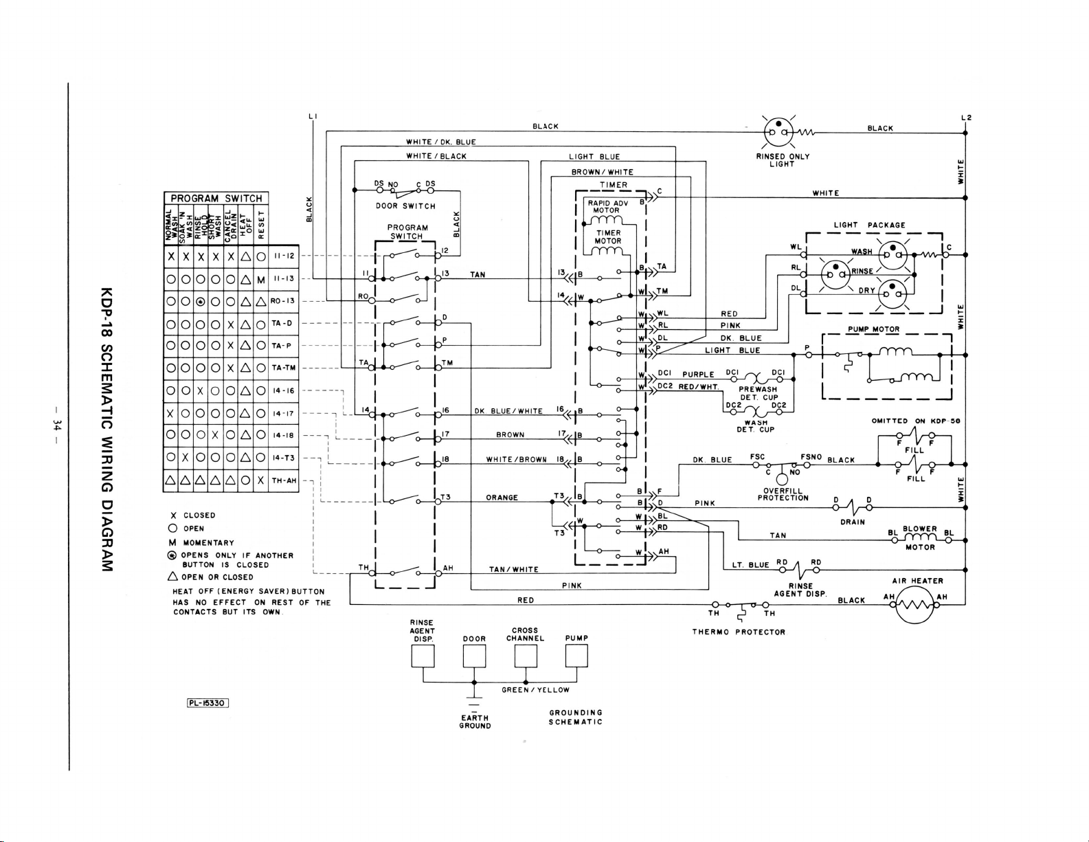
~I
c
"
-p
~
00
(I)
(")
:::c
m
3:
l>
-f
(")
:;
JJ
2
C)
c
l>
C)
JJ
l>
3:
PROGRAM SWITCH
...J
~:r:
~~
~~
~;
oJ:
"'
X X
0 0 0 0
0 0
0 0
0 0 0 0
0 0 0 0
0 0 X 0
X 0 0
0 0 0 X
0
X 0 0
6 6 6 6
X CLOSED
0
OPEN
M MOMENTARY
@OPENS
BUTTON
6 OPEN
HEAT
HAS
CONTACTS BUT ITS
...J
....
wz
.....
~§
~i
X X
® 0
0 0
w"-
g~
:r:O
..
"'
~i
..
,o
X6
0
6
0
6
X6
X6
X6
0
6
0 6
0
0 6
0 6
6 0
ONLY
IS CLOSED
OR
CLOSED
OFF(ENERGY
NO
EFFECT
....
"'
"'
"'
0:
0
M 11-13
6
0
0
0
0
0
0
0
X
IF
ANOTHER
SAVER)BUT
ON
OWN
L I
WHITE I OK
WHITE I
OS
<
0
"'
~
..
...J
~
CD
11-12
--------ij-
L._f-+-+-
_
R0-13
TA
TA· P
TA-TM
14-16
14-17
14-IB
14-T3
TH-AH
__
-0
------
---- - I I I w DCI
- -
----,
I I I I I
----,
L-
I
--..., L __
: I r- ()-<
-i
~
- ---
.,
i I I I ()-< I I c
I I I I B I . F I
: ~ _____
: I I
I I
: I
: 1 I
~----
rON
REST
THE RED
OF
.
NO
~
DOOR
SWITCH
PROGRAM
SWITCH
'c--,
I:CI
:i-4.-o-
--
I -
RO -
I
--r t
~
--
-1-
TAj
14.J
"'f
__
l_~o-
-1-
~
--1-
l..o.-------o
TH j I
L
__
I
. BLUE /
BLA
CK
C
~
"'
5 I
CD
12
tl
13
TAN
]I
oJ
I -
1-.-0
t.._p
L I
TM I I
16
OK
r
L17
LIB
T3
AH
_j
RINSE
AGENT CROSS
DISP. DOOR
. BLUE I WHITE
WHITE/BROWN
ORANGE
TAN /
BR
OWN
WHITE
CHANNEL
BLACK
LIGHT
BROWN I
r.:--
I RAPID
I
ll__fiy-n_
13
~
•
14
•w
I w
I
16
~
''
I 0 WASH
17~H
IB
~
T3/
/ B
1;:
lw
rcv------v
T3
L--
PINK
PUMP
/
'
r.::
e.:s_
BLUE RINSED ONLY
WHITE
TIMER
-
-,
,,c
ADV Bl
I~
~
I I I
L._
TIMER
MOTOR
o-o-----'
K>--
~
I
I
B~,
TA
V ( ~ •
wl
™
I
WL
WT
RL
wl
DL
wl ~
P
_--
wl
~
DC2
RED/WHT
I
II
f-
I
~ B ~~~
~ w 1\.-J>='B~=----.;::""'-<:::-----,
,
RD
~"
wl~~
~-J
RED L - - ..L -
PINK
--
OK. BLUE
LIGHT
BLUE
PURPLE
DCI
.
P-RE~
~ET.CUP
2
DC
DET. CUP
OK. BLUE
PINK
---
l DRAIN
I
LT
THERMO
PROTECTOR
"''
LIGHT
WHITE
r-----
WL_J
RLj
,_.....,,_/ \
oL]
~'
r-
P j j
rY
D,£_1
'
l
2
DC
FSC FSNO
.Q
NO
OVERFILL
PROTECTION o D i
TAN
. BLUE
R_:>
,--<.R:>D-----------~
RINSE
AGENT
DISP
.
BLACK
LIGHT
PACKAGE
WASH
, . /
"'}
~\RINSE/'-_../'-.
DRYL:e:{
~
'-
PUMP MOTOR i
- - - -
~
c;-
------
OMITTED
BLACK
BLACK
ON
FFILLF
F
FILL
BL~
MOTOR
A~IR
HEATER
AH
L2
"'
~
J:
I
ic
t
1
1
_j
t
--,
I
I
_j
KDP-~8
F
"'
....
AH
I
PL-15330
C2
I
SJ SJ
_l
GREEN I YELLOW
EARTH
GROUND
GROUNDING
SCHEMATIC
g
Page 34

~I
WARNING
ELECTRICAL CONNECTIONS
SHOULD
BE
AN
CE WITH THE NATIONAL
ELECTRICAL CODE OR
SUCH C
PROGRAM
~~~~z~~~~~r~~~
_Jill I
~~
~~~~~~~~~j~~o
OIOIOI*IO
OIOIOIOIOIOIO
0
"
~
...
00
(I)
m
::0
m
(I)
(I)
n
::I:
m
s:
)>
:::!
n
~
::0
2
C)
0
)>
C)
::0
)>
s:
XIXIXIXI
X X 0 X X ·X X !::; 0
0 0 0 X 0 0 X
X 0 X 0 0 0 0
o X 0 0 0 0 0
X 0 X X X X 0
OIOIOIOIOIO
X CLOSED
0 OPEN
M
MOMENTARY
* CLOSED
IS
PUSHED.
{::, OPEN
INDEPENDENT
MADE
OD
ES
IN FORCE.
SWITCH
~~--'~1
IO I
OI6IO
XIXIXI
IXI
UNTIL
ANOTHER
OR
CLOSED-
OF
IN ACCORD-
....
~
~
...
~
I61M
610
[::,
0
!::;
0
[::,
0
!::;
0 CP- P
6IO
BUT TON
CONTACT
BUTTON
II-
12
14-10
14-16---
14-17
I4-15!
TA-P
.
RINSE
AGENT
Ll
"'
u
<(
-'
"'
,---l
----
, I
--
,:__ -t
•---,
~
--+
~-
-+
--L--1
---L
-
__
,_
PROGRAM
SWITCH
CROSS
BLACK
"'
~
11
3"'
" BROWN
DK
. BLUE
BROWN / WHITE
LT. BLUE
PINK
TAN / WHITE
RED
RINSED
WATER
LIGHT
ONLY
BLACK
...
>-
:I:
:1:
e71-tole7
L _
. _
MOTOR
AIR
HEATER
_j
PROTECTOR
_j
AH
...
':::
:I:
:1:
...
>-
i:
:1:
THERMO
I
L_~l
---
PUMP
THI-ITH
L_.:.J
THERMO
PROTECTOR
I
IAN
-'~L
BLACK
BLOWER
··---- +
[
PL
-14!f3I)
9 2
EARTH
GROUND
'9'
PART
.:.~g,~:.
GROUNDING
SCHEMATIC
l;J'
9
OF
LI
GHT
PAC KAGE
Page 35

KDC
TIMER
SEQUENCE
CHARTS
KDC
~
-
NORMAL
PUMP
FILL
PUMP
DRAIN
PUMP
FILL
DRAIN
PUMP
FILL
PU
DRAIN
PUMP
RINSE
PRE
IST
2ND PRE-WASH
. 3RD PRE-WASH
MP
WASH
-
FILL
DISP.
DET.
PUMP
DRAIN
PUMP
AFTER
1ST
FILL
DRAIN
PUMP
2ND
FILL.
AGENT
PUMP
DRAIN
MP
PU
OFF
MP
PU
SCAVENGER
OFF
PUMP
BLOWER
HEATER
AIR
BLOWER ONLY
RESET
Event
-
AFTER
DISP.
WASH
RINSE
RI
NSE
OPT.
WASH
k
ll
..
0
..
::;
~<
c
~E:
§.
~~~~
p.
....
XX
XXX
XX
XX X
XX
XXX
XX X
XX
XXX
XX
XX X
XX
XXX
X
XX
XX
X
XX
XX
XXX
X
XX
XX
XXX
XX
XX
XX X
XX
X
XX
XX
X
XX
X
X
X
X
X
CYCLE
~
~
~
X
Per
Event
k
;
0
.
Min
"'
0 40 0 40
0
_u
u
0
0
0
0
I
I
I
0
I
4 30
I
0
I
I
0
I
I 0
0
0
0
0 30
2 55
0 10 30
X
XX
2I
7
X
2
PROGRAM
Time
Elapsed
otal
T
of
at End
Event
Min.
Sec.
56 I
30
45 2
42
56
45 5
22
30
0
0
22 9
30 10
30
0
22
30
0
22
30
20
45 26
I5
20
50
20
5
Sec.
29
4
5
7
8
9
II
16
I7
17
18
19
20
2I
21
24
25
26 15
26 45
7 5
30 0
52
59
61
36
6
5I
14
36
6
6
6
28
58
30
0
0
22
52
52
14
44
44
55
15
0
10
0
20
25
p
R
0
G
R
E
s
s
ponents are energized and should be
the
functioning during each period
of
program cycle.
REMEMBER:
timer, certain
control
the
These are: (
switch, (2)
In addition to the
other
switches also
electrical power supply.
door interlock
the
1)
over fill control switch,
the
(3) the program switch, and ( 4) the
thermal protectors.
These charts show which com-
timer
NOTE:
The
manually by turning
cator knob clockwise
may be advanced
timer indi-
the
the desired
to
position.
These timers may vary approximate ly
seconds. The total time may
10
to
7
vary for different tim er manufacturers.
KDC
~
PUMP
FILL
PUMP
DRAIN
PUMP
RESET
RINSE/HOLD
...
s
0
::E
~2:
Event
::s
·~
f-<P;
XX
XXX
XX
XX
XX
X
-·~
==~
~Cl
CYCLE
"
Min.
X
58
0
0
0
0
0
PROGRAM
Time
Per
Event
Sec.
40
56
30
45
24
10
Total
End
at
Min
61
.
0
1
2
2
3
Elapsed
Event
of
Sec.
40
36
6
51
15
25
p
R
0
G
R
E
-
s
s
j
36
-
Page 36

KDI TIMER SEQUENCE
CHARTS
NORMAL
KDI
Event
PUMP
F1LL 1ST
K~~~~M~~
PUMP
. 2ND PRE-WASH X X X X 0
f1LL
DRAIN
DET. DISP.
PUMP
DET.
PUMP X X X 4 43 16
DRAIN
PUMP X X X 0
PUMP
f1LL
~f1~L~L~&~ru~N~S~E~AG~E~N~T~D~ffi~P~OP~T~.~X~X~~XX~~~~xtt=tl=t=~0
f-:,f1LL
PUMP X X X
DRAIN
WASH
-
PRE
.---------------
N1
DISP. #2 X X
AFTER
, 2ND
AFTER
2ND
WASH
~i~i~x
RINSE X X X X 0
RINSE
CYCLE
:5
ci.
0
i3
::g
.S
~19
...:
~
=
E E
~
.S
iZ
&!
!=
X X 0 50 0 50
X X X 0
X X X 0
X X X X 0
X X X
X X X
X X X X
X X X
X X X X
~~
12
++
PROGRAM
Time
Z
;3
'"'
Event
E
'"'
coJ
Go~
1------.--4---r---l
,S
~
Min.
.S
05
i~~~-4~~~~~~~~
I
X I 30
I
2
I
Per
Sec .
58
49
58
45
30 46
32
0
7
27
15
~~2
5
0
0
Total Elapsed G
at
Event E
n.
Mi
I
·
3
4
5 25
8 18
11
17
17
20
20
~1=t~52~~
2
24
25 7
p
R
0
End of R
5
5
Sec.
~
48
~5~~-4
42
l
40
30
13
l
13
40
37
1
52
These charts
ponents
are energized and should be
show
which
functioning during each period
program cycle.
REMEMBER:
timer, certain
electrical
the
contro
These are:
switch, (2)
(3)
thermal
NOTE:
manually
cator
l
(1)
the
program switch, and (
the
protectors.
timer
The
by
clockwise
knob
In addition
other
switches also
power
door
the
over fill
control
may be advanced
turning
the
to
to
supply.
interlock
timer
the
position.
ese timers may vary app roxim ately
Th
time
10 seconds. The
to
7
vary
for
different
total
timer
manufacturers.
com-
the
of
the
switch,
the
4)
indi-
desired
may
ONLY X X X
BLOWER
RESET
KDI RINSE/HOLD
~
8
I~
....
...:l
8~
:u
~
16
-.s
e
:9
~::::::~-.
·~
s::
p..r..Q
E-o
....
X
XX
XX
XX
XXX
XXX
XXX
XXX
PUMP
F1LL
PUMP
DRAIN
PUMP
RESET
Event
X X
CYCLE
Per
Event
.5
70
Sec.
0
0
0
0
0
Min.
X
41
71
74 7
16 26
2
PROGRAM
Time
Elapsed
50
58
20
45
27
47
Total
at
Min.
74
End
0
1
2
2
3
of
Event
Sec.
50
48
8
53
20
7
26
- 37 -
p
R
0
G
R
E
s
s
l
Page 37

KDI TIMER SEQUENCE CHART
SOAK'N WASH
KDI
~
Event
PUMP
1ST PRE-WASH
F1LL
PUMP
DRAIN
PUMP
F1LL 2ND
DET.
PUMP
PUMP
PUMP
DRAIN
PUMP
FILL
DRAIN
PUMP
F1LL -
DET.
PUMP
DRAIN
PUMP
F1LL.
DRAIN
PUMP
F1LL 2ND
DRAIN
PUMP
F1LL 3RD
RINSE AGENT DISP.
PUMP
DRAIN
PUMP
PUMP
PUMP
DRAIN SCAVENGER
PUMP
PUMP
BWWER
AIR HEATER
BWWER
RESET
DISP.
OFF
3RD
WASH
DISP
1ST
OFF
OFF
PRE-WASH
n
PRE-WASH
*2
AFTER
AFTER
AFTER
ONLY
RINSE
RINSE
RINSE
OPT
~
.9
0
;!;
=
~~e
..
~f:
XX
XXX
XX
XX
XX
XXX
XX
XX
X
XX
XX
XX
XXX
XX
XX
XXX
XX
XX
XX
XX
XXX
XX
XX
XX
XX
XX
XX X X
.
XX
XX
XX
X X
XX
XX
XX
X
X
X
X
X
CYCLE
ci.
il
I~
c
~
~~~
~.s
"'
ciS
""11
!S~ii:
X
X
X
X X
X
X
X
u
~
·"'"
~]
X
X
X
X
X
X
X
X
X
X
X
X
H2
X
X
X
X
X
X
X
X
X
X
X
X
X
X
XX
XXX
XX
X
PROGRAM
Time
Per
Event
Sec.
.
Min
0
0
0
u
I
4 0
9
I
0
I
0
0
I
4
I
0
I
I
0
I
0
0
I
0
0 50
0
0 30
I
0
19
3
2
50
58
45
30
30
33
27
12
45
27
30
30
35
27
30
27
30
27
'"
45
43
15
23
15
51
41
0
0
0
0
9
0
Elapsed
Total
at End of
Event
Min.
0
I
2
5
5 16
14
24 7
25 7
25 34
26
27
27
29 28
29
34 26
35
35
37
38
38
40 20
4
41 47
42
43 8
43 45
44
45
46
46
46
47
48
48 26
68
71
74 7
Sec
These charts show which com-
p
R
0
G
R
E
s
s
.
50
48
53
1
12
34
!
46
31
58
l
51
26
53
23
l
23
50
20
4'
l
30
13
3
18
!
48
II
26
26
j
26
ponents are energized and should be
the
functioning during each period
of
program cycle.
the
es
to
also
REMEMBER:
timer, certain
In addition
other
switch
control the electrical power supply.
These are:
switch, (2)
(1)
over fill control switch,
the
interlock
door
the
(3) the program switch, and (4) the
thermal protectors.
NOTE:
manually
cator
The timer may be advanced
timer indi-
by
knob
turning
clockwise
the
to
the
desired
position.
These timers may vary approximately
seconds. The total time may
10
to
7
vary for different timer manufacturers.
-
38
-
Page 38

KDP
TIMER
SEQUENCE
CHART
KDP
~3RD
&!SP.
NORMAL
PL-1~3Z4
I
Event
PUMP
F1LL
1ST
PREWA
PUMP
DRAIN
MP
PU
FILL
2ND PREWASH
PUMP
RAPID ADVANC E
PUMP
DRAIN
PUMP
RINSE
PUMP
PUMP
PUMP
AIR
PREWASH
HI
PUMP
FILL,
MAIN
DET
PU
DRAIN
PUMP
FILL,
PUMP
DRAIN
PUMP
FILL
UMP
RAPID
PUMP
DRAIN
PUMP
DRAIN SC AVENGER
PUMP
BLOWER ON
BLOWER ON
DWELL
RESET
•When Door Unlatched
WASH
. D!SP. 12
MP
1ST
AFTER RINSE
2ND
AFTER
ADVANCE
AGE
NT DISP.
OFF
OFF
HEAT & BLOWER
SH
RINSE
WASH
a... .::
~;
~
::0
Q,
E < E::: ·c;....;...;
;::.:&:.:a~~
X X
X X X
X X
X X X
X X
X X X
X X
X X X
X X
X X X
X X
X X X
X X X
X X
X X X
X X X
XX
X
X X X
X X
X X
X X
X
XX
X X
X X X
X X
X X X
X X
XXX
X X X'
X X
X X X
X X
X
X X X
X X
X
X
X
X
X
CYCLE
~ ~
gg.g
"iS
iS~
~
~
a:
XX
~
~
a:i
X '
X X
PROGRAM
·
Time
Per
~
Et
X 0 13 0 13
X I 18 I
X 0 19 I
X 0 H 2 U
X 0
X I 18 4
X 0 18 5 0
X 0
X 0
X I 0 6 27
X 0
X I 30 8
X I 29 9 15
X 0 21 9
X I
X 0 38
X I W I «
X I 0
X 4 4
X I Q•
X 0 40
Event
,_j.jl-:--+----1--.-----1
= 0
Min
. Se
X I 30
X 0 0
X I 0
X 0
X I
X 0 29
X 0 3
X I 0
X 0 46
X 0 55
X 0 20
X 0
0
X
0
X
0 I
X
0
22 I
X
13
0 43
X
0
39
12
15
39
39
30
52
30
18
11
21
c.
0
3'
Total
Elapsed
at
E~~~tf
Min. Se
3 4
5
5 7
11
18
20 4
22 24
23 3
4 3
25 2
25 5
6
26
7 46
28
28 58
29 28
29 58
30 16
31
31
53
66 40
6 23
p
R
0
~
E
ss
c.
31
50
42
12
6
36
36
36
14
44
51
6
18
19
ponents
functioning during each period
are energized and should be
of
the
program cycle.
REMEMBER: In addition
timer, certain
control
the
These are:
switch, (2)
the
(3)
various
program switch and, (
thermostats and thermal
other
electrical
(I)
the
over fill
switches also
power
the
door
control
to
the
supply.
interlock
switch,
4)
the
protectors.
NOTE: On
the
KDP model,
the
timer
should be manually advanced ONLY
by
removing the dial from
(TL-72139) and placing
like
hub
on
the
timer shaft,
rotating
the
the
in which
pointing
which
surface
the
hub
slowly clockwise
desired position. The pointer on
hub
will indicate the cycle phase
the
to
is
of
that
already
the
timer.
timer
is
portion
printed
the
tool
the
pointer-
then
to
operating by
of
the dial
on
the
These charts show which com-
- 39 -
Page 39

KDP
TIMER
SEQUENCE CHART
KDP
PL-15323
ON
PUMP
FILL
PUMP
DRAIN
PUMP
2ND
FILL,
PUMP
DISP.
.
DET
PUMP
SOAK
PUMP
DRAIN
PUMP
FILL,
PUMP
DRAIN
PUMP
FILL
DISP. N
DET.
PUMP
DRAIN
PUMP
liST
PUMP
DRAIN
PUMP
FILL.
RINSE
PUMP
DRAIN
PUMP
MP
P
PUMP
DRAIN
PUMP
PUMP
BLOWER
HEAT
AIR
BLOWER
DWELL
RESET
SOAK'N
I
Event
1ST PREWASH
PREWASH
II
OFF
PUMP
PREWASH
3RD
WASH
MAIN
RINSE
AFTER
RINSE
AFTER
3RD
DISP.
AGENT
OFF
SCAVENGER
OFF
ON
BLOWER
&
WASH
.
" g
B •
.j;
0
"<
:u~
o.
E
.
·-
h
.....
X X
XX
X
X
X
X X X
X
X
X X X
X X
X
X X
X X
X
X X
X X X
X X
XX
X
X X
X X X
X
X
X X X
X X X
X X
X X X
X X
X X X
X X
X X X
X X
X X X
X X
X X X
X X
XX
X
X
X
X X
X X X
X X
X
X X
X X X
X X
X
X
X
X
X
X
CYCLE
ci.
Na
.
• 0
·-
lg
l;
o.
15~
"iS
-;...;
iS.!l
~~
X
PROGRAM
Time
"
B
~~
.53
"
~...i..j..j
iii:tiO:ci
X
X
X
X
X
X
X
X
X
X
X
X
X
X
X
X
X
X
X
X
X
X
X
X
X
X
X
X
X
X
X
X
X
X
X
X
X
X
X
X
X
X
X
Per
Event
Sec .
Min.
13
0
18
I
19
0
55
0
39 3 24
0
I
30
18
0
37
I
50
2
0
4
36
9
0 15
I
39
0
30
I
I
0
I
0
30
I
I4
4
0
I
40
0
30
I
30
0
0
I
39
0
30
I
38
I
0
I
39
0
18 46
I
30
I
46 48
0
55
0
20 50 I
0
0
30
0
30
0
18
0
51
0
11
0
X
X·
X
I 75
22
21
13
0
43
0
3'
Elapsed
Total
End
at
Event
n.
Mi
0
I
I
2
4 54
-,
6 49
13
23
26
28
36
37
38 42
3
40
40
42
43
44
45
48
49
51
51
52
53
5 I
88
89
of
Sec.
13
45
39
39
24
24
p
R
0
G
R
E
s
s
I
50
j
12
ponents are energized and should be
the
functioning during each period
of
program cycle.
addition to the
REMEMBER:
timer, certain
In
other
switches also
control the electrical power supply.
the door interlock
These are:
(l)
switch, (2) the over fill control switch,
(3) the program switch and, ( 4) the
These charts show which com-
15
54
32
32
32
I2
12
12
51
21
59
59
8
56
0
46
41
23
53
11
2
14
5
18
various
protectors.
NOTE:
should be manua
by removing the dial from the tool
(TL-72139) and placing the pointerlike hub on the timer shaft, then
rotating
the desired position. The pointer on
the
in which the timer
pointing to that portion
which
surface
thermostats and thermal
model, the timer
KDP
the
On
y advanced
ll
slowly clockwise to
hub
the
will indicate the cycle phase
hub
operating by
is
of
already printed on the
is
the timer.
of
ONLY
the dial
•wh
en
Door Unlatched
40 -
-
Page 40

KDP
TIMER SEQUENCE
CHART
KDP
KDP SHORT
RINSE/HOLD
PL
-
·~
322
I
Eve
nt
RAPID
ADVANCE
PU
MP
FILL
PUMP
RAPID
ADVA NCE X X X X
MP
PU
DRAIN
PU
MP
PUMP
OFF
P U
MP
DRAIN
PU
MP
PUMP
RAPID
D
WELL
RESET
*When
SCAVE
OFF
ADVA N
Door
NG
ER X X X X
CE
Unlatc
hed
CYCLE
0 "
- 0
0 -
:.
0
0.
-=-
E<
§ a
0.
..
f=ci
XX
X X 0
X X X
X X X X
X X X
X X X
X X X
X X X
X X
X X X
X
X X
X X
X X
X
X
WASH
PL-1~
32,
J
"
0 " "'"' -
o.s
:.
0
0.
-=-
e-
Event
PU
MP X X
F1
LL, 1ST
PREW
PUMP
RAPID
DET
. D!SP.
PUMP
RAPID ADVA
PUMP
DRAIN
PUMP
F1
LL
DE
T. D!SP. 12 X X X
PUMP
RAPID
P
UMP
DRA
IN X X X
PU
MP
ILL 1ST
F
PU
MP X X
RAPID
UMP
DRAIN
PUMP
F1LL
, 2
RINSE
UM
P
P
DRAI N
PUM
P
PUMP
UMP
DRAIN SCAVENGER
PUM
P
PUMP O
BLOWER ON
AIR HEAT
BLOW
ELL
DW
ESET
R
ASH X X X
ADVANCE
HI
NC
E
MAIN WAS
H
ADV
ANCE
AFTER
RINSE X
ADVANCE X
ND
AFT ER RINSE
GENT
DISP. X
OFF
FF
& BLOWE R
ER
E<
0
:;:
~0::
~~
....
X X X 0 23 1
X X X
X X
X X
XX
X
X X
X X
X
XX
X X
XXX
X X
X X
XX
XX
X X
X X X
X X
X
XX
X
X X
X
X X
X X
X
X X
X X X X 0 30
X X 0 18 21 58
X
X X
X
X
X
X
lg "
NQ
~
~
c
.
-~~
~
~
~
~
H
"
~
g..:i
iri~O::O
.5
~~
CYCLE
ci.
!l
-
N"'
g.~
g
~
c
~
.;
~
~=
X
XX
"
~...:i
lii
= Q
PROGRAM
Eve
Pe r
nt
c.
30 0
32
55 4
52
18 6
15
Tim
0
~
-
~~
_..,
..:i ..:i
Min. Se
0 15 0 45
1 30
0
0 3
0 15
X
0
0 20
0
0 30
0 30 6 12
0
0
X
0 25
0 23
0 3'
PROGRAM
Time
"
B
~~
]
:3
Pe r Total El
Eve
..;i
;i.:o
X
X
X
X
X
X
X
X
X
X
X
X
X
X
X
X
X
X
X
X
X
X 1
X
X
X
X
X
X
,j
X
nt
Min.
S
ec.
13
0
1 18 1
0 3 1 57
1 1 4
0 15 4 47
0 15 5 2
0
38
1 30 8 10
1
30 8 56
21 9
0
0 3 9 20
0 4 44
1 0 10 44
40
0
1
30
0 34
0 3
15 13 46
0
1 0
39
0
18
1 30 17
0 46 18 33
55 19 28
0
0 20
0
52
0 30
0 51 22 49
0
11
22 1 45 1
13
21
43
0
0
3'
e
Total
Elaps
at End of
Eve
nt
Mi
n. Sec.
30
2
15
2
47
2
50
3 5
4
20
12
5
5 42
30
6 4 5
7
10
7
33
apsed
at E
nd
of
Event
Mi n. Sec .
0 13
31
54
3
6 40
17
11
24
12 54
13
28
13
31
14 46
15
43
16
4
19 48
20
40
21
10
21
40
23 0
22
58
59
5
p
R
0
G
ed
R
E
s
s
!
0
!
ponents are energized and should be
functioning during each pe
ri
od of the
program cycle.
REMEMBER: In addition to the
timer,
c
ontr
These are:
ce
rtain
oth
er switch
es also
ol the electrical power supply.
(1)
th
e door interlock
switch, (2) the over fill control switch,
(3)
th
e pro gram switch and, ( 4) the
v
ariou
s thermostats and thermal
protec
tor
s.
l
These charts show which com-
NOTE: On
should be manua
by remo ving the dial from the to ol
(TL-72 139) and placing the pointe
like hub on the timer shaft, then
rotating
e desired position. The pointer on
th
the hub will indicate
p
R
0
G
R
E
s
s
in which the timer is operating by
pointing to
which
surface
th
e KDP model, th e timer
ll
y advanced ONLY
the hub slow
th
at portion
is
already printed on the
ly clockwi
th
e cycle phase
of
of the tim er.
se
to
the dial
r-
j
j
j
*When Door Unlatched
-
41
-
Page 41
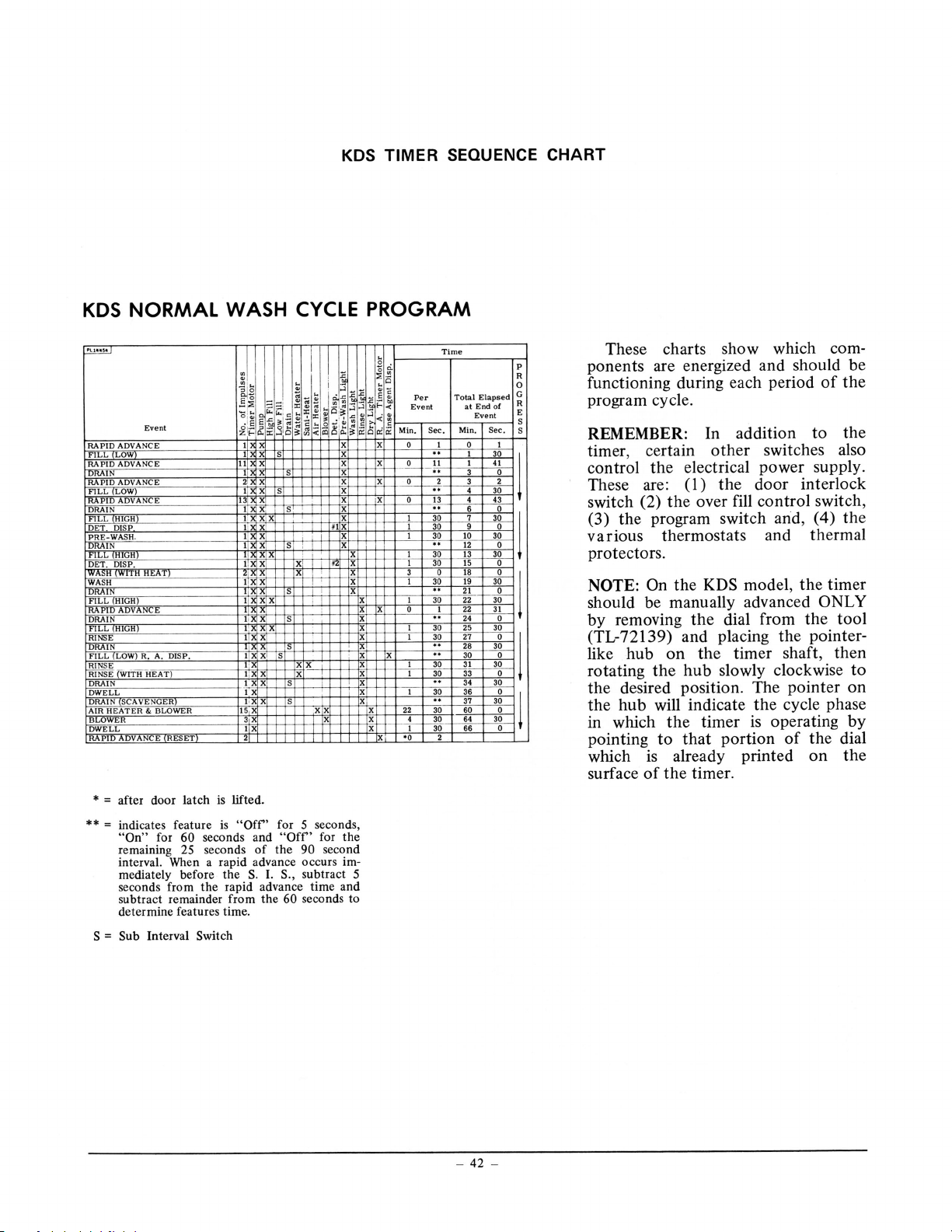
TIMER SEQUENCE CHART
KDS
NORMAL WASH
KDS
Event
DVANCE
RAPJDA
LOW
f1LL
RAPID
I
N
DRAI
L
f1L
DET
DET.
H (WITH
AS
I W
~N~~===========t~
~~
~s
~~~fu~
f1LL
RAPID
DRAIN l 1
LL
FI
LL
FI
~(WITH
IN
DRA
DWELL ' X
DRAI
HEATER
AIR
BLCWER 3
LL
OWE
PI V
=
*
=
**
=
S
E
NC
ADVA
GH
HI
DISP I
DISP. I
HEAT X
GH)
HI
N E X X X 0 I
DV
GH
HI
DISP. I
) R. A.
LOW
HEAT )
R I•
NGE
VE
SCA
N
BLOWER 15 X X 22
&
RESET
E
N
after door latch is lifted.
indicates feature
On"
"
remaining 25 seconds
interval. When a rapid advance occurs
mediate ly before
seconds from the rapid a
ubtr
s
ete
d
Sub
60
r
fo
act remainder from
rmine features time.
Interval
I
I
3 X
I
I·
~~tt$s~=t~
~
I
I
I,
)IHX
I
"Off
is
seconds and
S.
e
th
Switch
CYCLE
X
S
X
S
X,
lQ
X X X
lC
X
X X
S
X
X X X
S
X
X
~~,_rr
S
~-F
X
~
S
X
X X X 4
X X
for
'
Off
"
the
of
,
S.
I.
ance time and
dv
60
the
X 6
X
*I
X
N
X
X X 3
~x~tt~l=t~
~
tti
~
, I I 30
X
~
second
5
for the
'
secon d
90
im-
subtract
seconds to
PROGRAM
~
~
::; ·-
~~
Per
~
.§
.i:
Event
<
l-
·-
f----r--t-
~
<
~
ci
Q
X
X
X
~
~,_
x
f.
X "
s,
5
Sec.
Min.
0:
0 I 0 I
13
0
I 30
I 30
I 30
;
••
I 30
ro
•o
:
-
I 30
I 30
" 30 0
~g
~
·
~
t
30 60 0
30
X
Time
Elapsed
Total
End of R
at
E,ve_nt---i
--
Sec.
Min.
4 43
0
30
7
0
9
0
15
O
18
0
33go~
~
21921~
42
?i=
~
31
22
0
24
30
25
t-+
H-
~
0
~
3
-r~
4
~
3
-r~
·
2
0
36
30
37
30
64
0
66
p
R
0
G
~
S
l
l
1
These charts show which com-
ponents are energized and should be
the
functioning during each period
of
program cycle.
REMEMBER:
timer, certain
control
the
These are:
In addition to the
other
switches also
electrical power supply.
the door interlock
(1)
switch (2) the over fill control switch ,
(4) the
(3) the program switch
various
thermostats and th ermal
and,
protectors.
model , the timer
KDS
the
NOTE:
should be manually advanced
by
(TL-72139) and placing
like hub
rotating
the desired position. The pointer
the
in which
pointing
which
surface
On
ONLY
e tool
removing
on
the
e dial from
th
the timer shaft, then
slowly clockwise
hub
th
e pointer-
th
on
hub will indicate the cycle phase
timer
the
portion
that
to
already printed
is
timer.
the
of
operating
is
of
by
the dial
the
on
to
-
42
-
Page 42

KDS
SOAK'N
SCRUB
KDS
CYCLE
TIMER SEQUENCE CHART
PROGRAM
Time
These charts show which com-
ponents are energized and should be
functioning during each period
program cycle.
Event
nLL
(HIGH X X X X I 30
I
SOAK
E-
H X X X X I 30
P
PRE-WASH WITHOUT HEAT X X X I 30
N
nLL
HIGH
PRE-WASH
PRE-WASH WITH HEAT
SUA
I<
DRAIN
F1L HICH I X X X X I 30
RINSE I X X X I 30
~D~RA~I~N~S~C~A~VE~N~G~ER~)~=====+~I~X~X++
1-i
ffi
HEATER
BLOWER 3 X X 4 30
DWELL I
RAPID ADVANCE RESET 2
& BLOWER 15 X X X 22 30
X X X 4 30
XX
S X
X X X X I 30
XX
XX
s4=~~~~~~~:t~'~'~~~~~
4
X I
X
X 3 0
X I 30
••
30
••
30
'0
2
I
7
12
16 30
18
19
21 0
22 30
24 0
27
28 30
37
40 30
45
46 30
48
51
52
54 0
55 30
5
60 0
61
63 0
64 30
66
67 30
69
70 30
7
73
75
76
78
79 30
106
108
30
30
_0_
30
30
30
30
30
_jl_
30
_II_
0
0
0
0
0
0
0
0
REMEMBER:
timer, certain
In addition to the
other
control the electrical power supply.
These are:
switch (2)
(1)
the door interlock
the
over fill control switch,
(3) the program switch and, (4)
various
thermostats and thermal
protectors.
NOTE:
On the KDS model, the timer
should be manually advanced ONLY
by removing the dial from the tool
(TL-72139) and placing the pointerlike hub on the timer shaft,
rotating the hub slowly clockwise to
the desired position. The pointer
the hub will indicate the cycle phase
in which the timer
pointing
to
that
portion
which is already printed on the
surface
of
the
timer.
of
switches also
is
operating
of
the dial
the
the
then
on
by
* = after door latch
**
= indicates feature
"On"
for 60 seconds and
remaining
interval. When a rapid advance occurs im-
mediately before the
seconds from the rapid advance time and
subtract remainder from the 60 seconds to
25
is
lifted.
is
seconds
"Off'
of
S.
I.
for 5 seconds,
"Off'
the 90 second
S., subtract 5
determine features time.
S
= Sub Interval Switch
for the
-
43-
Page 43

KDS
SANI
CYCLE
KDS
PROGRAM
TIMER SEQUENCE CHART
~
.
~
~"
~0
.§~
=-
0'"'
""iZc::
. E E §
RAPID
FILL
RAPID
DRAIN 1 X X
RAPID
FILL
RAPID
DRAIN
FILL
DET.
PRE-WASH
DRAIN 1 X X
FILL
DET .
WASH WITH
WASH
DRAI N
FILL
RAPID
DRAI N
FILL
RINSE
DRAIN
FILL
SAN! OWE:
SAN! RINSE I X
DRAIN
DWELL
DRAIN
AIR
BLOWER
DWELL
Event
ADVANCE 1
LOW 1 X X s X
ADVANCE
ADVANCE
LOW)
ADVANCE
(HIGH 1 X X X
D!SP.
HIGH
D!SP.
HEAT
HIGH
ADVANCE 1 X X X
HIGH
LOW R A
SCAVENGER
HEATER & BLOWER
DAD ANCE
D!SP
RESET
~
~;&:x35
l!XX
2XX
!XX
s
13 X X
IX
1 X X
1 X X X
!XXX
1 X X N X
2XX
XX
I
lXX
!XXX
1 X X
I X X X X
1 X X X
I X
X
I X X s X
1
X X
1 X
1 X X
I X X s X
15 X X
3X
X X
2
* = after door latch is lifted.
indicates feature
**
=
"On"
for
remaining
interval. When a rapid advance occurs im-
mediately before
seconds from the rapid advance time and
subtract remainder from the
determine features time.
***
= plus water heating time.
****
hold for heating water.
Int
erval Switch
Sub
s
60
seconds and
25
seconds
is
"Off'
the S.
of
I. S., subtract 5
I~
..,_
g
11
~3
~0
~-"
..
~
~
<Jl
"Off'
~.
t:,.;
~~
X
X
X
X
N X
X
for the
X
X
X
X
·
;;
s X
s X
s
s
s X
s X
s X
for 5 seconds,
the 90 second
60
seconds to
s,~
0.
~~
Per
§I~
~~~~
I-<
:%
~.J
~I&
X
X
Event
-~
<
~
c s
r2
Min. Sec.
ci~
X
0 I 0 I
..
X
X
X
X
X
11
0
..
0
..
0
..
1 30 7
1
3
..
1 30 13
1 30 15 0
3
I 30
..
I 30
0
..
1 30
1
30
..
..
....
I
30
..
I
30
..
22 30
4 30 ***64
Ttme
Total Elapsed G
at
End
of
Event
Min.
Sec.
I 30
1 41
3 0
2 3 2
4 30
13 4 43
6 0
10
12 0
0 18 0
19 30
21 0
22 30
1 22
24
25
27 0
28
0 0
•••3 0
···33
•••
34
***36
***37
...
60
***66
30
30
30
30
31
30
30
30
30
30
0
0
0
0
0
p
R
0
~
s
j
!
j
1
j
These charts show which components are energized and should be
functioning during each period
of the
program cycle.
REMEMBER: In addition
timer, certain
control
These are:
switch (2)
(3)
various
the
elec
(1)
th
e over fill
th
e program switch and, (
thermostats and thermal
other
tri
switches also
cal power supply.
the
door interlock
contro
to the
l swi
tch
4) the
protectors.
NOTE: On
should be manua
by removing
th
e KDS model,
ll
y advanced ONLY
the
dial from
the
the
tim
tool
er
(TL-72139) and placing the pointerlike hub
rot
ating the hub slowly clockwise
th
e desired position. The pointer on
the hub
in which
pointing to
which is already printed on
surface
on the timer shaft , then
will indicate the cycle phase
th
e timer
th
at portion
is
operating by
of
the dial
of the timer.
to
th
,
e
-
44
-
Page 44

KDS
TIMER SEQUENCE CHART
KDS
IRAPII
***
RINSE/HOLD
f!W'HI
Event
>ADVANCE
FILL
WW
DRAIN
liXPm
RAPID
ADVANCE
REZER
.
RAPID
ADVANCE
* = after door latch
**
= indicates feature
"On"
remaining
= Pump pauses for three 1 second periods
= Sub Interval Switch
S
.
for 60 seconds and
25
interval. When a rapid advance occurs immediately before the
seconds from the rapid advance time and
subtract remainder from the 60 seconds to
determine features time.
in this section
seconds
of
CYCLE
.
.
~u
-~
0.
~-..
,g
E E
0
s
I
I
is
lifted.
is
"Off'
for 5 seconds,
of
the 90 second
S.
I.
rapid advance.
~
.
Clll-~
~-
.
~=·
~
~~~
"Off'
S.
, subtract 5
PROGRAM
s,!i
-
~~
:E~
...
..
--~
rc
.....
t
=.s~
X
X
X
XXX
X
·-
~~
~~
.:
X 0 I
X 0
X •o 2
...
~iS
~..:
for the
lg-"
Per
Event
Min.
0
n
0 32
Sec.
..
Ill
..
40
Time
Total
Elapoed
at
End of E
Event S
Min.
0 I
3 40
4
Sec.
30
4lf
30
0
p
R
0
~
s
l
These charts show which com-
ponents are energized and should be
of
functioning during each period
the
program cycle.
REMEMBER:
timer, certain
In addition
other
switches also
to
the
control the electrical power supply.
(1)
These are:
the door interlock
switch (2) the over fill control switch,
(3) the program switch and, (4)
various
thermostats and thermal
the
protectors.
NOTE:
On the KDS model, the timer
should be manually advanced ONLY
by
removing
the
dial from the tool
(TL-72139) and placing the pointer-
on
like hub
rotating
the
desired position. The pointer
the
hub
in which the timer
pointing
which is already printed
surface
of
the timer shaft, then
the
hub slowly clockwise
to
on
will indicate the cycle phase
is
operating by
to
that
the
portion
timer.
of
the dial
on
the
-
45-
Page 45

KDS
TIMER
SEQUENCE CHART
KDS
f'illllil
SHORT
Event
N E
PID
DV
FILL
HIGH
DISP. I X
DET.
PRE-WASH I X
DRAIN
FILL
HIGH
DET
DISP I X X X
RAPID
ADVANCE (WASH)
DRAIN
FILL
HIGH
RINSE I X
DRAIN
RAPID
ADVANCE
FILL
LOW
R.
DWELL
RINSE WITH HEAT I X
DRAIN
DWELL
DRAIN
AIR
HEATER
BLOWER
DWELL
LI<JI.PID
A. DISP. I X X
SCAVENGER I X
& BLOWER
ADVAN E
* = after door latch
indicates feature
**
=
"
On"
remaining 2.5 seconds
interval. When a rapid advance occurs im-
mediately before
seconds from
su
btr
act remainder from the 60 seconds
WASH
I~
RE•ET
is
lifted.
for 60 seconds
is
the
the
rapid advance
CYCLE
~
.
.!'l"
o
.§~
-
~
~~E~
~~=~'~
XX
lXXX
X
X X
X
I X
lXXX
3XX
I X X
lXXX
X X
lXX
3XX
X
X
I X X
I X X
X
15
X
3X
IX
"Off'
and
of
S.
I.
determine features time.
Timer
motor
***
=
the rapid advance motor
thereby decreasing the 90 second increment
by
31
= Sub
S
Int
is advancing
seconds.
erval Switch
at
PROGRAM
:c
.:;_
.
"
I~·
~~
~
~13
X •
$.o
7
3:
-~
~
1:
oa~~
~iS
~~
..
~;
~~
X
X
F c
* X
s X
*
s X
s X
s
XX
X X
s X
s X
XX
X
for 5 seconds,
"Off'
for
the 90 second
S., subtract 5
the same time
is
the
time
and
advancing,
"
;lg
::;
--
~~
Per
§I~
f-<
..,
<I~
Iii~
X 0
X
X 0
X
X
Event
Min. Sec.
••o
I
I
I
I
0 3
I
I
I 30
I 30
I
22
4 30
I 30
•o
..,_
~~~~
.
.Sit
0:0
X
X
X
X
X
X
X
to
31
59
30
30
..
30
30
..
30
30
..
3
..
..
30
..
30
2
Time
Total
at
Min. Sec.
0 31
3 0
4
6 0
7
9
9 3
10 30
12
13
15
15
16
18 0
19
21 0
22
24
46
51 0
52 30
Elapsed G
End
of
Event
'0
30
0
0
30
0
3
30
30
30
0
30
p
R
0
R
E
s
s
I
I
j
These charts show which com-
ponents are energized and should be
of
functioning during each period
the
program cycle.
REMEMBER: In addition
timer, certain
control
the
These are:
other
switches also
electrical power supply.
(1)
the door interlock
to
the
switch (2) the over fill control switch,
(3) the program switch and, (4) the
various
thermostats and thermal
protectors_
NOTE: On
the
KDS model,
the
timer
should be manually advanced ONLY
by removing
the
dial from
the
tool
(TL-7213 9) and placing the pointerlike hub on the timer shaft , then
rotating the hub slowly clockwise
the desired position. The pointer
the hub will indicate
in which
pointing
which
surface
the
timer
to
that
is
already printed
of
the
timer_
the
is
portion
cycle phase
operating
of
to
on
by
the dial
on
the
KDS
PLATE
~
Event
RAPID
ADVANCE••
I RAPID ADVANCE
AIR
HEATER
RAPID
REZERO
RAPID
& BLOWER
ADVANCE
ADVANCE
WARM
.
.
.!'l
"
I~
o
.5~
-"
0.
i_E
53 X X
12
X
3X
I X
2
CYCLE
.
"
.
"-
X •
~~
s::""'7
-;~c
E
l~
•
~:;:o
a~~
* = after door latch is lifted.
**
= Pump pauses for three 1 second periods
in this section
of
rapid advance.
PROGRAM
:c
:3
.....
~
~
lg~~
~~c;;~
X
:t
'.c
~~~~;
XX
XX
21g
~~
·"
·-
:E
.s,~
_
....
<
.
~
'"'I<
~
Min.
"
a~
X 0
XX
17
X
XX
X
• 0
X
Per
Event
Sec.
0 3
0
I
Time
Total
Min. Sec.
53 0
4
3
27
2
Elapsed
at End of
Event
0
18
18
19
p
R
0
G
R
E
s
s
53
56
0
3
j
30
 Loading...