

Page 1
OM-2094
To Order Parts Call 1-888-702-5326 - https://monsterfloorequipmentparts.com
110100
Revised 01/01
Revised 02/01
Revised 03/01
Revised 05/01
Revised 06/01
Revised 07/01
Revised 08/01
Operation and Maintenance Manual
Jet-Ex 5D Generator Sets
1.
Hobart Brothers Company (hereinafter called HOBART) warrants that each new and unused Hobart Ground
Power Equipment, (hereinafter called the PRODUCT) is of good workmanship and is free from mechanical defects,
Series 500285
Hobart Brothers Company
Ground Power Division
Troy, Ohio 45373
U.S.A.
Page 2
WARRANTY
To Order Parts Call 1-888-702-5326 - https://monsterfloorequipmentparts.com
HOBART BROTHERS COMPANY, TROY, OHIO, U.S.A.
GROUND POWER DIVISION
1. Hobart Brothers Company (hereinafter called HOBART) warrants that each new and unused Hobart Ground
Power Equipment, (hereinafter called the PRODUCT) is of good workmanship and is free from mechanical defects,
provided that (1) the PRODUCT is installed and operated in accordance with the printed instructions of HOBART,
(2) the PRODUCT is used under the normal operating conditions for which it is designed, (3) the PRODUCT is not
subjected to misuse, negligence or accident, and (4) the PRODUCT receives proper care, lubrication, protection,
and maintenance under the supervision of trained personnel.
2. This warranty expires 15 months after shipment by HOBART to the first user, or 12 months after installation,
whichever first occurs.
3. This warranty does not apply to: primary and secondary switch contacts, cable connectors, carbon brushes, fuses,
bulbs, and filters unless found to be defective prior to use.
4. Hobart DOES NOT WARRANT THE FOLLOWING COMPONENTS: Engines (gasoline or diesel),storage
batteries, engine starters generators, alternators, regulators, governors, tires, axles,transmissions, and cable
retrieving devices. Many of the foregoing components are warranted directly by the manufacturer to the first user
and serviced by a worldwide network of distributors and others authorized to handle claims for component
manufacturers. A first user’s claim should be presented directly to such an authorized component service outlet.
In the event any component manufacturer has warranted its component to HOBART and will not deal directly with
a first user then HOBART will cooperate with the first user in the presentation of a claim to such manufacturer.
Under NO circumstances does HOBART assume any liability for any warranty claim against or warranty work
done by or in behalf of any manufacturer of the foregoing components.
5. This warranty is extended by HOBART only to the purchaser of new PRODUCTS from HOBART or one of its
authorized distributors. The PRODUCTS purchased under this warranty are intended for use exclusively by the
buyer and his employees and by no other persons and, therefore, there shall be no third party beneficiary to this
warranty.
6. A claim of defects in any PRODUCT covered by this warranty is subject to HOBART factory inspection and
judgment. HOBART’S liability is limited to repair of any defects found by HOBART to exist, or at HOBART’S
option the replacement of the defective product, F.O.B. factory, after the defective product has been returned by
the purchaser at its expense to HOBART’S shipping place. Replacement and exchange parts will be warranted for
the remainder of the original Warranty, or for a period of ninety (90) days, whichever is greater.
7. UNDER NO CIRCUMSTANCES whatsoever shall HOBART and its authorized distributors be liable for any special
or consequential damages, whether based on lost goodwill, lost resale profits, work stoppage impairment of other
goods or otherwise, and whether arising out of breach of any express or implied warranty, breach of contract,
negligence or otherwise, except only in the case of personal injury as may be required by applicable law.
8. Continued use of the PRODUCT(S) after discovery of a defect VOIDS ALL WARRANTIES.
9. Except as authorized in writing, this warranty does not cover any equipment that has been altered by any party
other than HOBART.
10. THERE ARE NO WARRANTIES WHICH EXTEND BEYOND THE DESCRIPTION ON THE FACE HERE OF.
HOBART MAKES NO WARRANTIES, EXPRESSED OR IMPLIED, OF MERCHANTABILITY OR FITNESS FOR
A PARTICULAR PURPOSE.
11. HOBART neither assumes nor authorizes any person to assume for HOBART any liability in connection with the
PRODUCTS sold, and there are no oral agreements or warranties collateral to or affecting this written Warranty.
This warranty and all undertakings of HOBART thereunder shall be governed by the laws of the State of Ohio,
United States of America.
AT ALL TIMES, SAFETY MUST BE CONSIDERED AN IMPORTANT FACTOR IN THE INSTALLATION,
SERVICING AND OPERATION OF THE PRODUCT, AND SKILLED, TECHNICALLY QUALIFIED PERSONNEL
SHOULD ALWAYS BE EMPLOYED FOR SUCH TASKS.
WARNING
Page 3

OM-2094 / Operation and Maintenance Manual
To Order Parts Call 1-888-702-5326 - https://monsterfloorequipmentparts.com
Jet-Ex 5D / Series 500285 / Generator Set
Safety Warnings and Cautions
WARNING
CALIFORNIA PROPOSITION 65 - DIESEL ENGINES. Diesel engine exhaust
and some of its constituents are known to the State of California to cause
cancer, birth defects and other reproductive harm.
WARNING
IMPORTANT
1.
General
Equipment that supplies electrical power can cause serious injury or death, or damage to other
equipment or property. The operator must strictly observe all safety rules and take precautionary
actions. Safe practices have been developed from past experience in the use of power source
equipment. While certain practices below apply only to electrically-powered equipment, other practices
apply to engine-driven equipment, and some practices to both.
2.
Shock Prevention
Bare conductors, or terminals in the output circuit, or ungrounded, electrically-live equipment can fatally
shock a person. Have a certified electrician verify that the equipment is adequately grounded and learn
what terminals and parts are electrically HOT. Avoid hot spots on machine. Use proper safety clothing,
procedures, and test equipment.
The electrical resistance of the body is decreased when wet, permitting dangerous currents to flow
through it. When inspecting or servicing equipment, do not work in damp areas. Stand on a dry rubber
mat or dry wood, use insulating gloves when dampness or sweat cannot be avoided. Keep clothing dry,
and never work alone
ELECTRIC SHOCK can KILL. Do not touch live electrical parts.
ELECTRIC ARC FLASH can injure eyes, burn skin, cause equipment damage,
and ignite combustible material. DO NOT use power cables to break load and
prevent tools from causing short circuits.
IMPROPER PHASE CONNECTION, PARALLELING, OR USE can damage
this and attached equipment.
Protect all operating personnel. Read, understand, and follow all instructions in
the Operating/Instruction Manual before installing, operating, or servicing the
equipment. Keep the manual available for future use by all operators.
a. Installation and Grounding of Electrically Powered Equipment
Equipment driven by electric motors (rather than by diesel or gasoline engines) must be installed
and maintained in accordance with the National Electrical Code, ANSI/NFPA 70, or other applicable
codes. A power disconnect switch or circuit breaker must be located at the equipment. Check the
nameplate for voltage, frequency, and phase requirements. If only 3-phase power is available,
connect any single-phase rated equipment to only two wires of the 3-phase line. DO NOT
CONNECT the equipment grounding conductor (lead) to the third live wire of the 3-phase line, as
this makes the equipment frame electrically HOT, which can cause a fatal shock.
November 1, 2000 Safety Warnings
Revised 03/01 Page 1
Page 4

OM-2094 / Operation and Maintenance Manual
To Order Parts Call 1-888-702-5326 - https://monsterfloorequipmentparts.com
Jet-Ex 5D / Series 500285 / Generator Set
Always connect the grounding lead, if supplied in a power line cable, to the grounded switch box or
building ground. If not provided, use a separate grounding lead. Ensure that the current (amperage)
capacity of the grounding lead will be adequate for the worst fault current situation. Refer to the
National Electrical Code ANSI/NFPA 70 for details. Do not remove plug ground prongs. Use
correctly mating receptacles.
b. Output Cables and Terminals
Inspect cables frequently for damage to the insulation and the connectors. Replace or repair
cracked or worn cables immediately. Do not overload cables. Do not touch output terminal while
equipment is energized.
3.
Service and Maintenance
This equipment must be maintained in good electrical and mechanical condition to avoid hazards
stemming from disrepair. Report any equipment defect or safety hazard to the supervisor and
discontinue use of the equipment until its safety has been assured. Repairs should be made by
qualified personnel only.
Before inspecting or servicing electrically-powered equipment, take the following precautions:
a. Shut OFF all power at the disconnecting switch or line breaker before inspecting or servicing the
equipment.
b. Lock switch OPEN (or remove line fuses) so that power cannot be turned on accidentally.
c. Disconnect power to equipment if it is out of service.
d. If troubleshooting must be done with the unit energized, have another person present who is trained
in turning off the equipment and providing or calling for first aid.
4.
Fire And Explosion Prevention
Fire and explosion are caused by electrical short circuits, combustible material near engine exhaust
piping, misuse of batteries and fuel, or unsafe operating or fueling conditions.
a. Electrical Short Circuits and Overloads
Overloaded or shorted equipment can become hot enough to cause fires by self destruction or by
causing nearby combustibles to ignite. For electrically-powered equipment, provide primary input
protection to remove short circuited or heavily overloaded equipment from the line.
b. Batteries
Batteries may explode and/or give off flammable hydrogen gas. Acid and arcing from a ruptured
battery can cause fires and additional failures. When servicing, do not smoke, cause sparking, or
use open flame near the battery.
c. Engine Fuel
Use only approved fuel container or fueling system. Fires and explosions can occur if the fuel tank
is not grounded prior to or during fuel transfer. Shut unit DOWN before removing fuel tank cap. DO
NOT completely fill tank, because heat from the equipment may cause fuel expansion overflow.
Remove all spilled fuel IMMEDIATELY, including any that penetrates the unit. After clean-up, open
equipment doors and blow fumes away with compressed air.
5.
Toxic Fume Prevention
Carbon monoxide - Engine exhaust fumes can kill and cause health problems. Pipe or vent the exhaust
fumes to a suitable exhaust duct or outdoors. Never locate engine exhausts near intake ducts of air
conditioners.
6.
Bodily Injury Prevention
Serious injury can result from contact with fans inside some equipment. Shut DOWN such equipment
for inspection and routine maintenance. When equipment is in operation, use extreme care in doing
necessary trouble-shooting and adjustment. Do not remove guards while equipment is operating.
Safety Warnings November 1, 2000
Page 2 Revised 03/01
Page 5

OM-2094 / Operation and Maintenance Manual
To Order Parts Call 1-888-702-5326 - https://monsterfloorequipmentparts.com
Jet-Ex 5D / Series 500285 / Generator Set
7. Medical and First Aid Treatment
First aid facilities and a qualified first aid person should be available for each shift for immediate
treatment of all injury victims. Electric shock victims should be checked by a physician and taken to a
hospital immediately if any abnormal signs are observed.
EMERGENCY
FIRST AID
8.
Equipment Precautionary Labels
Inspect all precautionary labels on the equipment monthly. Order and replace all labels that cannot be
easily read.
Call physician immediately. Seek additional assistance. Use First Aid techniques
recommended by American Red Cross until medical help arrives.
IF BREATHING IS DIFFICULT, give oxygen, if available, and have victim lie
down. FOR ELECTRICAL SHOCK, turn off power. Remove victim; if not
breathing, begin artificial respiration, preferably mouth-to-mouth. If no detectable
pulse, begin external heart massage. CALL EMERGENCY RESCUE SQUAD
IMMEDIATELY.
November 1, 2000 Safety Warnings
Revised 03/01 Page 3
Page 6

OM-2094 / Operation and Maintenance Manual
To Order Parts Call 1-888-702-5326 - https://monsterfloorequipmentparts.com
Jet-Ex 5D / Series 500285 / Generator Set
This page intentionally left blank.
Safety Warnings November 1, 2000
Page 4 Revised 03/01
Page 7

OM-2094 / Operation and Maintenance Manual
To Order Parts Call 1-888-702-5326 - https://monsterfloorequipmentparts.com
Jet-Ex 5D / Series 500285 / Generator Set
Introduction
This manual contains operation and service information for 28.5 V DC Generator sets identified as Jet-Ex 5D.
These units are available as stationary, skid- mounted units, or they may be trailer-mounted for portability.
Both versions are available with 14 V DC output capability.
Most information in the manual applies to the 28.5 V Jet-Ex 5D in general. Information which applies to
options and special equipment are listed in Appendix A.
The primary purpose of the manual is to provide information and instructions to experienced operators,
electricians, and mechanics who are not familiar with this equipment. The intent of the manual is to guide
and assist operators and maintenance personnel in the proper use and care of the equipment.
Read the instructions before starting the unit. Learn to use the manual and to locate information contained in
it.
The Table of Contents, which follows this Introduction, lists all Chapters, Sections, and the paragraph titles
within each Section. The location of each listing is identified by Chapter, Section and page number.
Each Chapter is divided into as many Sections as necessary. Sections are always referred to by a
combination Chapter-Section number, for example: 2-3 refers to Chapter 2, Section 3.
The material within each Section is divided into main subjects with applicable paragraph headings and
sub-headings as required. For example, a portion of the Description Section might logically follow this
arrangement and paragraphing:
Section 1. Description
1. Engine, Generator and Controls
a. Interior Panel
(1) Protective devices
a. Overload relay
(2) Contactors
Page numbers do not run consecutively throughout the manual. Each page is identified by the
Chapter-Section number in which it appears, and by a page number within the Chapter-Section. Therefore,
the first page in each Section is page 1. These identifying numbers appear in the lower, outside corner of
each page. Each page also bears a date located in the corner opposite the page number. This date is either
that of original issue, or of the latest revision. Any revision to the original text is identified by a heavy black line
in the left-hand margin. Illustrations follow a numbering system similar to page numbering. The first Figure in
each Section is Figure 1.
All tables, charts, as well as illustrations, are identified by Figure numbers to avoid confusion.
The general location of any particular information can be found quickly by running through the Table of
Contents. For example: to locate any adjustment information, a quick look at the Table of Contents shows that
“Adjustment / Test” is located in Chapter 2, Section 3, (shown as 2-3).
November 1, 2000 Introduction
Revised 03/01 Page 1
Page 8

OM-2094 / Operation and Maintenance Manual
To Order Parts Call 1-888-702-5326 - https://monsterfloorequipmentparts.com
Jet-Ex 5D / Series 500285 / Generator Set
Portions of the text are referred to by identifying the paragraph in which the referenced material may be
found. When referenced material is located in the same Chapter/Section as the reference, only the paragraph
identification is given, for example: (Ref. Para. 1, A) means that the material is to be found in paragraph 1, A,
of the same Section.
When referenced material is located in another Chapter/Section, both the Chapter and Section numbers and
the paragraph identification are given, for example: (Ref. 1-2, Para. 1, A) means that the referenced material
is located in Chapter-Section 1-2, and paragraph 1,a. within that Chapter-Section.
Components shown in illustrations, and the illustrations themselves, are referenced in a similar manner.
When this type of reference is made, the item number of the part and the Figure number in which it appears
are given, for example: (2, Fig.3) refer to item number 2 in illustration Figure 3 of the same Chapter/Section.
When a referenced figure appears in another Chapter/Section, the reference will include the Chapter/Section
number, for example: (2-3, 1, Fig. 4) tells the user that the information is in Chapter/Section 2-3, and to refer
to item 1 in Figure 4.
Once a Figure number reference has been established, the Figure number is not repeated and only the item
numbers of the parts involved are referenced, for example: “Loosen screw (2, Fig.6) slide out connector (4),
and remove brush (6).
When an item number is referenced without a Figure number, it always applies to the last preceding Figure
number mentioned in the text.
A collection of manufacturer’s literature is supplied as part of the information package.
If you have any questions concerning your Hobart Ground Power equipment, immediately contact our
Service Department by mail, telephone or FAX.
Write: Hobart Brother Company
Ground Power Division
Service Department
1177 Trade Road East
Troy, Ohio 45373
U.S.A.
In U.S.A. Call: (800) 422-4166 (Parts)
(800) 422-4177 (Service)
From Foreign Countries Call: (937) 332-5050 (Parts)
(937) 332-5060 (Service)
FAX: (937) 332-5121
(800) 367-4945 Toll Free in U.S.A.
Introduction November 1, 2000
Page 2 Revised 03/01
Page 9
OM-2094 / Operation and Maintenance Manual
To Order Parts Call 1-888-702-5326 - https://monsterfloorequipmentparts.com
Jet-Ex 5D / Series 500285 / Generator Set
Table of Contents
Chapter 1. Description/Operation
Section 1. Description 1
General 1
Special Features 1
Standard 1
Options 1
Orientation 4
Identification 4
Canopy 4
Engine, Generator, and Controls 4
General 4
Engine 4
Generator 9
Rectifier Assembly 9
Ammeter Shunt 9
Contactor 9
Control Box Assembly (Front) 11
Control Box Assembly (Inside) 15
Emergency Sutdown Device 15
Section 2. Preparation for Use, Storage or Shipping 1
Preparation for Use 1
General 1
Inspection/Check 1
Output Cable Requirements and Installation 1
Preparation for Storage 3
General 3
Temporary Storage 3
Long Time Storage 3
Preparation for Shipping 3
Section 3. Operation 1
General 1
Operating the Generator Set 1
Pre-start Inspection 1
Pre-start Instructions 1
Starting The Engine 3
November 1, 2000 Table of Contents
Revised 03/01 Page 1
Page 10

OM-2094 / Operation and Maintenance Manual
To Order Parts Call 1-888-702-5326 - https://monsterfloorequipmentparts.com
Jet-Ex 5D / Series 500285 / Generator Set
Generator Operation 3
Deliver Power 3
Stop Operation (Shutdown) 3
Adverse Weather Precautions 4
Chapter 2. Servicing / Troubleshooting
Section 1. Maintenance Inspection/Check 1
General 1
Maintenance Schedule 1
General 1
Maintenance Schedule Check Sheet 1
Time Intervals 1
Engine and Related Components 1
Inspection and Cleaning 3
Section 2. Maintenance Procedures 1
General 1
Lubrication 1
General 1
Lubrication Chart 1
Generator 1
Generator Controls 1
Engine 1
Servicing the Air Cleaner 4
Air Filter Cartridge Removal 4
Air Filter Cartridge Installation 4
Servicing the Fuel Filter 4
Drive Belt Service 4
Engine Cooling System 4
Radiator Cap Removal 5
Rust Inhibitor 5
Antifreeze 5
Battery Service 5
General 5
Battery Location and Accessibility 5
Battery Care 5
Liquid Level (If Battery is not Maintenance Free) 5
Cleaning the Battery 6
Testing a Battery 6
Generator Maintenance 7
General 7
Brush Service 7
Generator Revolving Field Brush Replacement 7
Table of Contents November 1, 2000
Page 2 Revised 03/01
Page 11
OM-2094 / Operation and Maintenance Manual
To Order Parts Call 1-888-702-5326 - https://monsterfloorequipmentparts.com
Jet-Ex 5D / Series 500285 / Generator Set
Section 3. Adjustment/Test 1
General 1
Testing the Generator Set 1
Pre-operational Test Procedures 1
Operational Tests 3
Voltage Regulator Adjustment 4
28.5 Volt Adjustment 4
Line Drop Compensation 4
Section 4. Troubleshooting Procedures 1
General 1
Troubleshooting Chart 1
Description 1
Use of the Troubleshooting Chart 1
Equipment for Troubleshooting 1
Safety Precautions 1
Diagrams 1
Connections and Wiring 1
Section 5. Troubleshooting Charts 1-8
Chapter 3. Major Overhaul
Section 1. Flexible Coupling 1
General 1
Coupling Screws (Routine Coupling Maintenance) 2
Disassembly 3
Separate Engine and Generator 3
Remove Coupling Assembly 3
Coupling Service 4
Coupling Installation and Reassembly of Engine Generator 5
Cleaning 5
Assembly 5
Run-In and Periodic Check 7
Chapter 4. Illustrated Parts List
Section 1. Introduction 1
General 1
Purpose 1
Arrangement 1
November 1, 2000 Table of Contents
Revised 03/01 Page 3
Page 12
OM-2094 / Operation and Maintenance Manual
To Order Parts Call 1-888-702-5326 - https://monsterfloorequipmentparts.com
Jet-Ex 5D / Series 500285 / Generator Set
Explanation of Parts List 1
Contents 1
Parts List Form 1
Section 2. Manufacturer’s Codes 1
Explanation of Manufacturer’s (Vendor) Code List 1
Section 3. Parts List 1
Explanation of Parts List Arrangement 1
Symbols and Abbreviations 1
Section 4. Numerical Parts List 1
Explanation of Numerical Parts List 1
Chapter 5. Manufacturer’s Literature
Appendix A. Options / Features
Table of Contents November 1, 2000
Page 4 Revised 03/01
Page 13
OM-2094 / Operation and Maintenance Manual
To Order Parts Call 1-888-702-5326 - https://monsterfloorequipmentparts.com
Jet-Ex 5D / Series 500285 / Generator Set
Chapter 1. Description/Operation
Section 1. Description
1. General
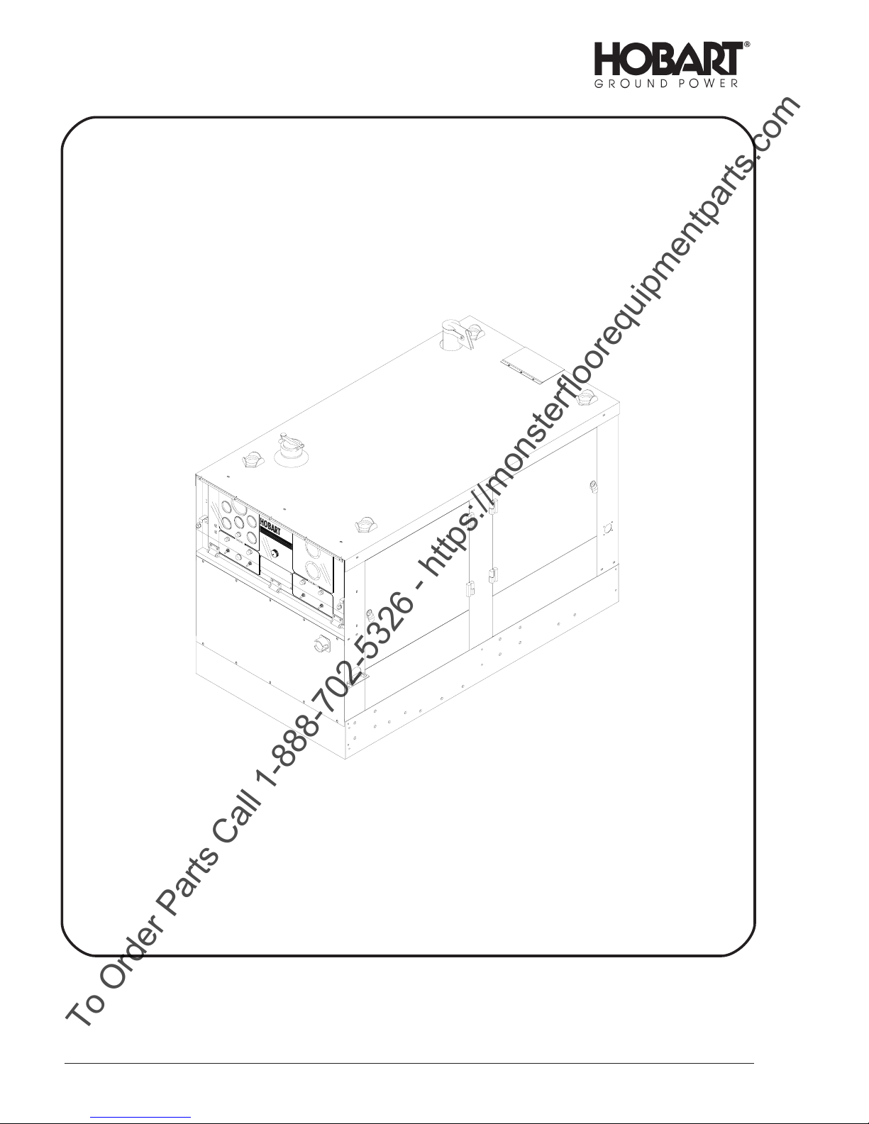
The Jet-Ex 5D units (Figure 1) covered in this manual are diesel engine driven, self-contained
generator sets manufactured by Hobart Brothers Company, Ground Power Division, Troy, Ohio U.S.A.
A basic unit is identified by a Series Number - 500285 - plus a dash number which defines a specific
configuration. The Series Number, plus the dash number, make up the Specification Number.
Part Number Mounting Configuration
500285-001
500285-002
Specification No. 500285-001 covers a trailer mounted unit rated at 28.5 Volts DC output. It is equipped
with a sheet metal canopy and four hinged engine compartment doors. Various options are available
for use with the basic unit. A few of these options are listed in paragraph 2.B below, but the complete
list of options are located in Appendix A.
The basic generator set is designed to generate and deliver 28.5 Volts DC power to an aircraft when its
on-board generators are shut down. In addition to providing continuous, regulated power to the aircraft,
the unit is also designed for starting any fixed-wing aircraft or helicopter which is equipped with an
external 28.5 Volts DC power receptacle.
2.
Special Features
a. Standard
The “Soft-Start” current limiting feature, recommended by most aircraft engine manufacturers,
provides the operator with controls to limit the inrush current to the aircraft engine’s starter. When
the operator presets this control, the generator will provide constant voltage to the preset current
value. The more current is increased beyond the preset current value, the voltage will decrease to a
minimum of 14 volts DC, after which the voltage will remain constant as more current may be
delivered beyond the preset current value. Limiting inrush current is recommended by most engine
manufacturers to protect the aircraft engine’s starter shear section. The current limiting control is
continuously adjustable from 300 amperes, which is recommended for helicopter and small turbine
starting, to 2000 amperes, required for starting larger aircraft engines when the control is turned
fully clockwise.
Trailer Mounted with Cable
Trays
Stationary Mounted with
Cable Hangers
b. Options (See Appendix A for complete list)
Chapters 1-5 of this manual describes a basic “no options” generator set. Appendix A lists the
options available for this unit. Below are the mounting configurations.
November 1, 2000 Chapter 1-1
Revised 07/01 Page 1
Page 14
OM-2094 / Operation and Maintenance Manual
To Order Parts Call 1-888-702-5326 - https://monsterfloorequipmentparts.com
Jet-Ex 5D / Series 500285 / Generator Set
Chapter 1-1 November 1, 2000
Page 2 Revised 07/01
Jet-Ex 5D Generator Set
Figure 1
Page 15
OM-2094 / Operation and Maintenance Manual
To Order Parts Call 1-888-702-5326 - https://monsterfloorequipmentparts.com
Jet-Ex 5D / Series 500285 / Generator Set
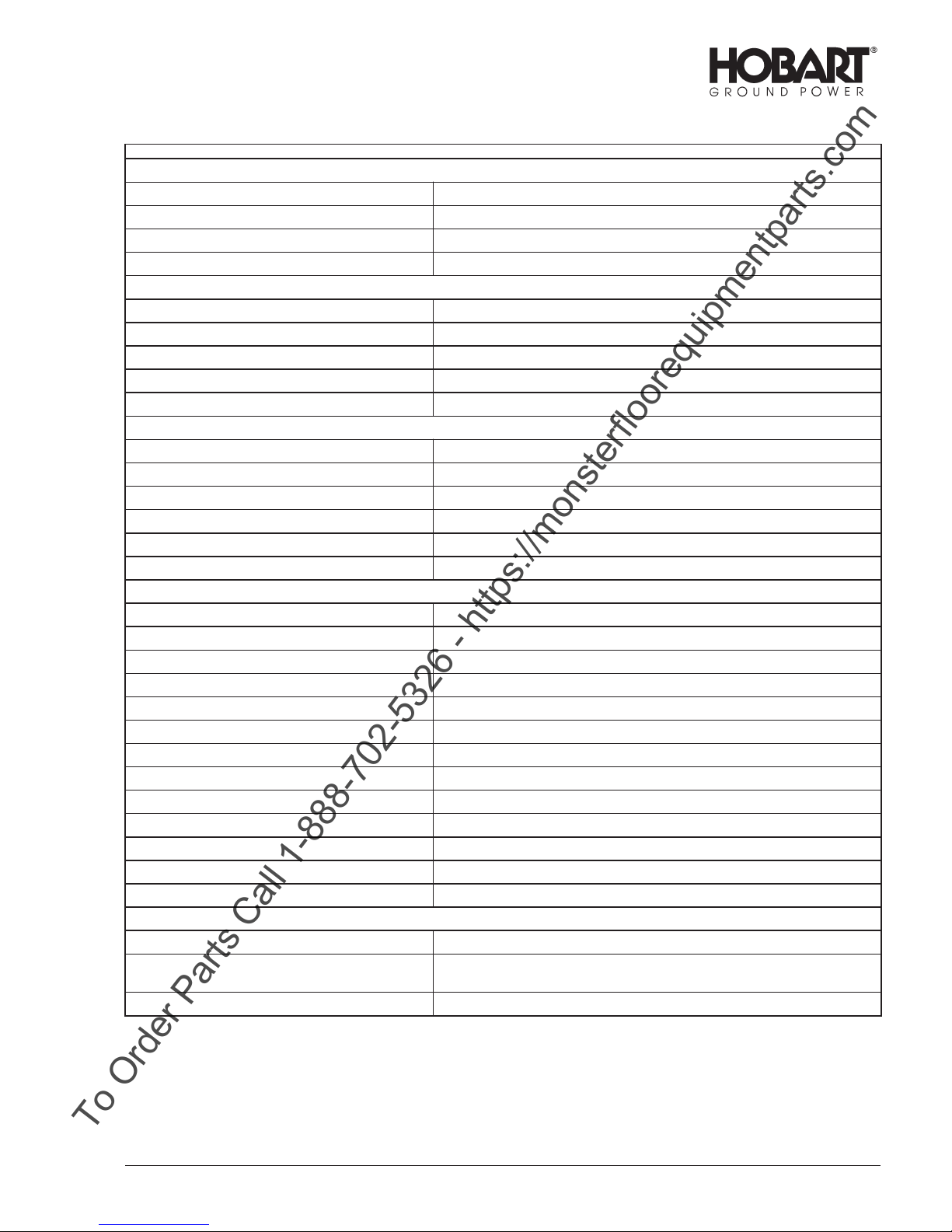
Unit with Stationary Mount (500285-002)
Length 68” (172.7 cm)
Width 37” (94 cm)
Height 46” (116.8 cm)
Weight (dry fuel tank) 2400 lbs (1088.6 kg) Approx.
Unit with Trailer and Cable Trays (500285-001)
Length 76.3” (193.8 cm)
Width 67” (170.1 cm)
Height 62” (157.5 cm)
Weight (dry fuel tank) 2670 lbs (1211 kg) Approx.
Ground Clearance 14” (35.6 cm)
Generator
Output Power Rating 17.1 kW
Voltage 28.5 volts DC
Rated Load Capacity 800 amperes continuous at 28.5 volts DC
Starting Current Capacity 2000 amperes maximum
Current Limiting Capability 300 to 2000 amperes, continuously adjustable
Operating Speed 2500 +/-50 RPM
Engine
Manufacturer Cummins Diesel
Model 4BT3.9
Type 4-cylinder, 4-stroke, direct injection
Fuel-Diesel recommended ASTM D975 66T Numbers 1D or 2D
Displacement 238 cubic inches (3.9 liters)
Rated Power at 2200 RPM 100 Horsepower (75 kW)
Oil Capacity (without filter change) 11.5 quarts (10.9 liters)
Coolant Capacity - engine only 7.4 U.S. Quarts (7 liters)
Coolant Capacity - system 4.5 U.S Gallons (17 liters)
Electrical System 12 volt DC, negative ground
Governed Speed at No Load 2500 +/- 50 RPM
Idle Speed 1000 +/- 50 RPM
Fuel Tank Capacity 20.5 U.S. gallons (77.6 liters)
Protective Devices
Generator 28.5 volt over voltage module trips at 32 to 34 volts.
Engine
Water Temp. Switch opens engine circuit at 210º F (98.8º
C)
Low Oil Pressure Switch opens at 20 PSI (138 kPa).
November 1, 2000 Chapter 1-1
Revised 07/01 Page 3
Page 16
OM-2094 / Operation and Maintenance Manual
To Order Parts Call 1-888-702-5326 - https://monsterfloorequipmentparts.com
Jet-Ex 5D / Series 500285 / Generator Set
3. Orientation
The radiator end of the Jet-Ex 5D is the front. Right and left are determined by standing at the rear of
the unit, facing it. The control panel is located at the rear.
4.
Identification
The Jet-Ex 5D unit is identified by Specification numbers as described in paragraph 1. There may be
any number of Generator sets with the same Specification number. Individual machines are identified
by a Serial number, assigned to one machine only.
Each generator set has an Identification plate attached inside the control box. This nameplate lists the
machines Model No. (Jet-Ex 5D), Specification No., Serial No., and electrical rating.
If any of the options described in paragraph 2.b. are included, they will be listed by name and part
number on a separate option nameplate located next to the Identification plate.
5.
Canopy
The standard canopy is a sheet metal enclosure which protects the engine, generator, and electrical
controls. It has four hinged doors to provide access for service and maintenance. A bolted on panel at
the rear (below the control box) provide access to the rectifier assembly. A Lexan window is mounted in
front of the control panel to allow observation of the instruments while protecting them from the
weather.
6.
Engine, Generator, and Controls
a. General
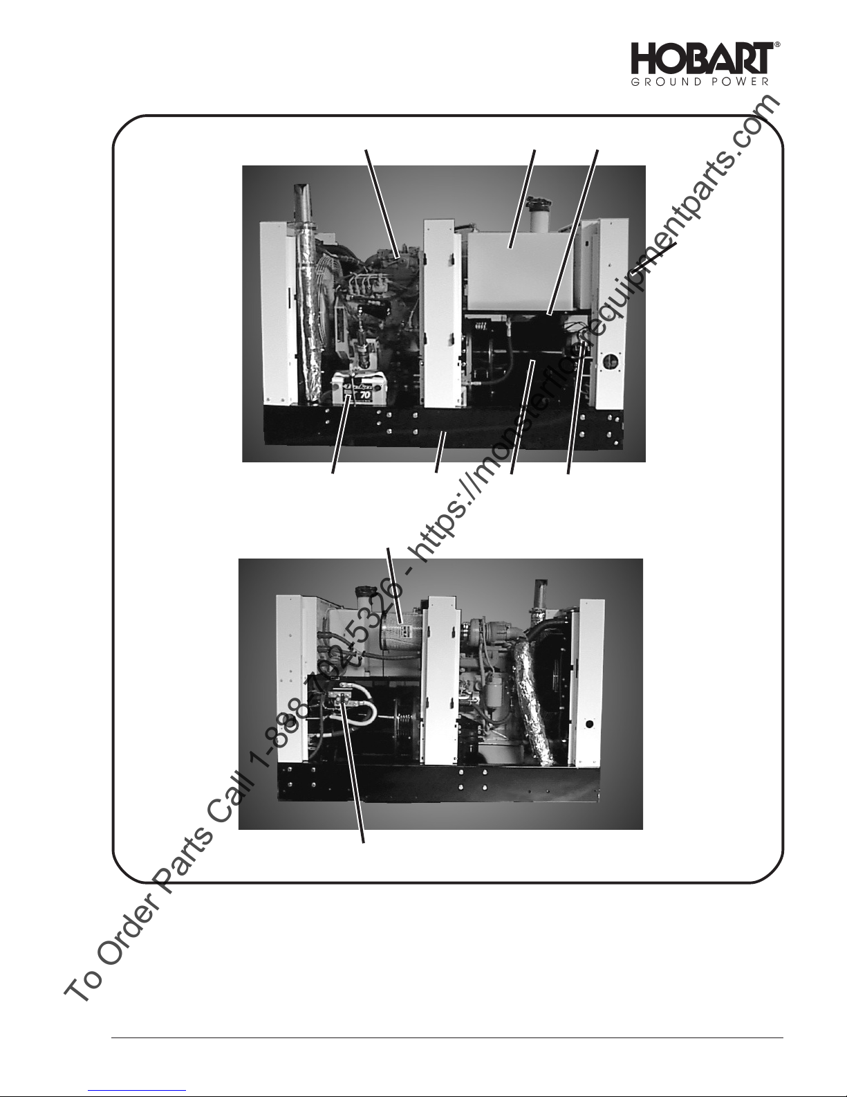
The engine (7, Figure 2) and generator (5) are mounted on a welded steel frame (6). A fuel tank
support (1) located at the rear of the unit supports the fuel tank (2) and provides a mounting frame
for the load contactor (10) and output terminals. The radiator (7, Figure 4) is mounted to the front
canopy and frame.
b. Engine
(1) General
The engine used in the Jet-Ex 5D generator set is a Cummins Model 4BT3.9 four-cylinder,
four-stroke, direct injection diesel engine. It has a 238 cubic inch (3.9 liter) cylinder displacement
and a 17.5:1 compression ratio. Engine firing order is 1-3-4-2.
A spring-loaded relief valve in the oil pump limits maximum pressure in the system. A full-flow oil
filter (3, Figure 3) cleans the oil before it enters the oil distributing system. A low oil pressure
switch is mounted on the engine block as a protective device. The fuel valve solenoid circuit is
wired through the contacts of this switch, which closes at 20 PSI (138 kPa). This prevents the
engine from continuing operation if oil pressure will not build up, and also shuts down the engine
if oil pressure drops radically during operation.
See the engine operator’s manual for additional engine specifications.
The generator and engine are mounted on a welded steel skid, and are enclosed by a sheet
metal canopy that bolts to the skid. Access to engine serviceable components (oil filter, air
cleaner, etc.) is through the doors on each side of the machine.
The rear panel is removable and permits access to the rectifier assembly.
Chapter 1-1 November 1, 2000
Page 4 Revised 07/01
Page 17
OM-2094 / Operation and Maintenance Manual
To Order Parts Call 1-888-702-5326 - https://monsterfloorequipmentparts.com
Jet-Ex 5D / Series 500285 / Generator Set
27 1
3
9
6
5
4
8
10
1. Fuel Tank Support
2. Fuel Tank
3. Control Panel
4. Rectifier Assembly
November 1, 2000 Chapter 1-1
Revised 07/01 Page 5
5. Generator
6. Frame
7. Engine
8. Air Cleaner
Generator Set Components
Figure 2
9. Battery
10. Contactor
Page 18
OM-2094 / Operation and Maintenance Manual
To Order Parts Call 1-888-702-5326 - https://monsterfloorequipmentparts.com
Jet-Ex 5D / Series 500285 / Generator Set
5
4
1
3
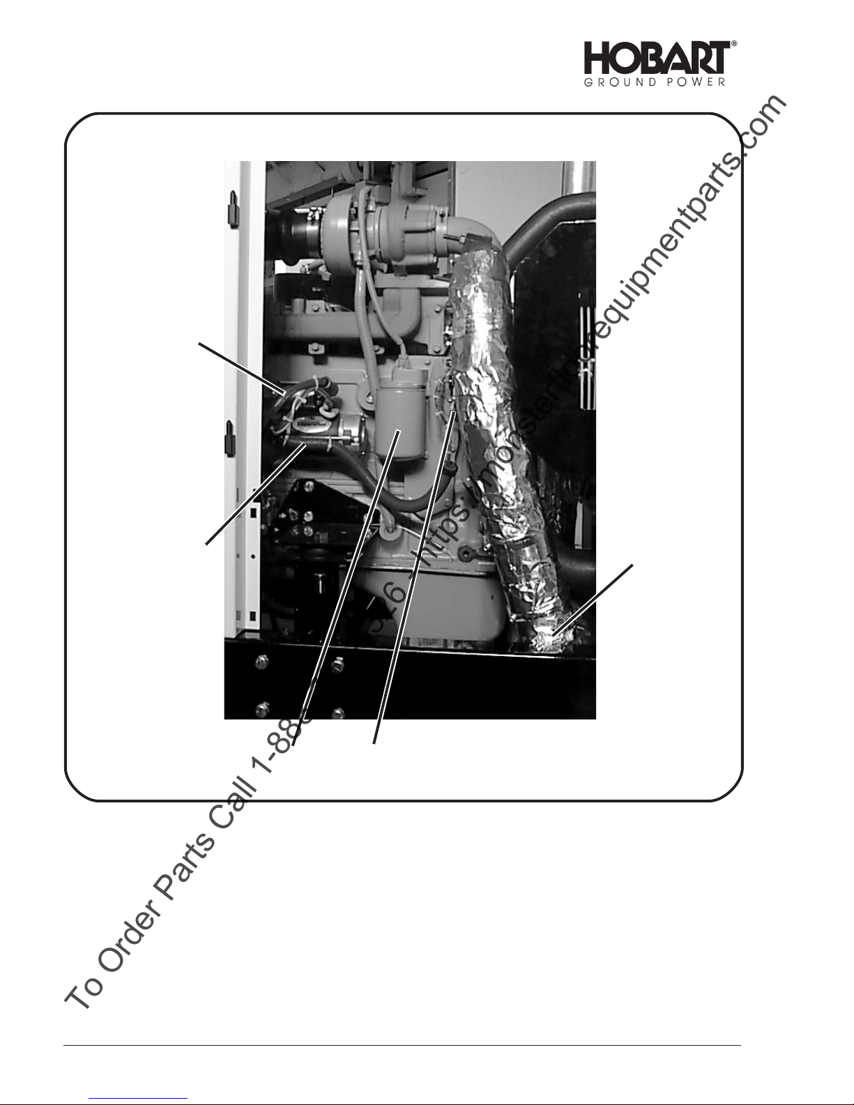
1. Muffler
2. Alternator
3. Oil filter
4. Starter
5. Starter solenoid
2
Chapter 1-1 November 1, 2000
Page 6 Revised 07/01
Generator Set Components
(Left Side)
Figure 3
Page 19
OM-2094 / Operation and Maintenance Manual
To Order Parts Call 1-888-702-5326 - https://monsterfloorequipmentparts.com
Jet-Ex 5D / Series 500285 / Generator Set
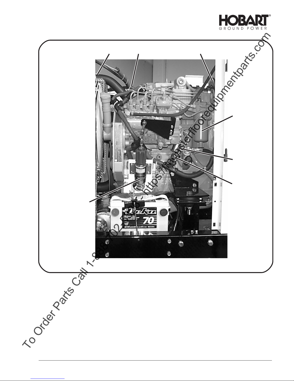
267
1
4
5
3
1. Fuel filter
2. Air cleaner
3. Throttle control assembly
4. Oil pressure sender
5. Oil pressure switch 20 psi (138 kPA)
6. Water Temp. Switch
7. Radiator
November 1, 2000 Chapter 1-1
Revised 07/01 Page 7
Generator Set Components
(Right Side)
Figure 4
Page 20
OM-2094 / Operation and Maintenance Manual
To Order Parts Call 1-888-702-5326 - https://monsterfloorequipmentparts.com
Jet-Ex 5D / Series 500285 / Generator Set
(2) Cooling fan
The cooling fan on the engine is designed to blow air out through the radiator rather than to draw
it in. This prevents hot air, heated by the engine, from entering the generator.
(3) Fuel system
The fuel system consists of a 20.5-gallon (77.6 liters) plastic fuel tank (2, Figure 2) with all the
necessary fittings and hoses.
(4) Alternator
The battery charging alternator (2, Figure 3) is rated at 65 amperes. The alternators
responsibility is to produce/regulate 12V DC for the generator sets internal electrical system.
(5) Starter solenoid
The starter solenoid (5, Figure 3) is mounted on the starter motor (4), on the right side of the
engine.
(6) Exhaust muffler (1, Figure 3)
This muffler helps deaden audible noise from the engine’s exhaust.
(7) Engine faults
The following is a table listing faults which may occasionally occur. Column two of the table
explains what happens in the engine’s circuitry when the fault occurs, and column three tells how
to return the generator set to service.
ENGINE FAULTS
Engine Fault Condition What This Fault Condition Does
Over Temperature Automatically removes power
from the fuel valve solenoid and
shuts down the engine
Low Oil Pressure Automatically removes power
from the fuel valve solenoid and
shuts down the engine
Clogged air cleaner or
other restriction in the
combustion air inlet.
Turns on the air cleaner
restriction indicating light
(16, Figure 5)
To Put the Generator Set Back
into Service:
a) Let the engine cool down
enough to check for low coolant
level and or faulty over
temperature switch. Restart
engine.
a) Let the engine cool down
enough to check for low oil level
and or faulty oil pressure switch.
Restart engine.
a) Replace clogged air filter if
needed; clean out the air intake
chamber. Restart engine.
Chapter 1-1 November 1, 2000
Page 8 Revised 06/01
Page 21

OM-2094 / Operation and Maintenance Manual
To Order Parts Call 1-888-702-5326 - https://monsterfloorequipmentparts.com
Jet-Ex 5D / Series 500285 / Generator Set
c. Generator
The generator (5, Figure 2) is a multi-phase, synchronous salient pole, revolving field, AC generator
whose output is rectified. The output is rectified by a rectifier assembly (4) made up of twelve
rectifiers connected into a full wave configuration. The generator is self-excited, receiving excitation
from a three phase full wave rectified stator winding. One positive and one negative brush in contact
with slip rings supply controlled excitation current from the stator winding through the voltage
regulator to the rotating field winding. The voltage regulator, controls the excitation current and
maintains a constant output voltage. Access to the brushes is through holes in the anti-drive end
bracket. The rotor is supported at the anti-drive end (slip ring end) by a single-row ball bearing. The
drive end is connected to the engine fly-wheel by a flexible disc and hub coupling assembly and is
supported by the engine main bearings. A radial-blade fan of formed and welded sheet metal
construction is mounted on the coupling hub and draws cooling air over the generator windings.
Air flows over the rectifier assembly (4, Figure 2) and then enters through the anti-drive end of the
generator and is discharged through openings in the flywheel housing at the drive end. The
generator housing assembly, which contains the generator stator, is bolted to the engine flywheel
housing.
d. Rectifier Assembly
The Rectifier Assembly (4, Figure 2) consists of two aluminum heat sinks with six diodes on each
heat sink. The rectifier assembly converts the AC output of the generator to 28.5 Volts DC.
e. Ammeter Shunt
The ammeter shunt is connected in the generator’s negative output circuit. It supplies a small
voltage proportional to output current for operation of the AMMETER (4, Figure 5), and to the
current limit circuit of the voltage regulator (2, Figure 6). This shunt is mounted on the negative heat
sink of the rectifier assembly (4, Figure 2).
f. Contactor K402 (10, Figure 2)
The load contactor, which is mounted on the right side of the unit below the fuel tank, provides a
safe and convenient means of connecting and disconnecting the generator from the load. Initial
power for closing the load contactor is supplied by the generator through the spring-loaded
momentary contacts of the CONTACTOR CONTROL toggle switch (7, Figure 5). Holding power, to
keep the contactor closed, passes through the normally open auxiliary contacts in the load
contactor. Output power connection is made by attaching the positive lead to the top terminal of the
load contactor, and the negative lead to the negative output terminal located above the load
contactor.
November 1, 2000 Chapter 1-1
Revised 07/01 Page 9
Page 22
OM-2094 / Operation and Maintenance Manual
To Order Parts Call 1-888-702-5326 - https://monsterfloorequipmentparts.com
Jet-Ex 5D / Series 500285 / Generator Set
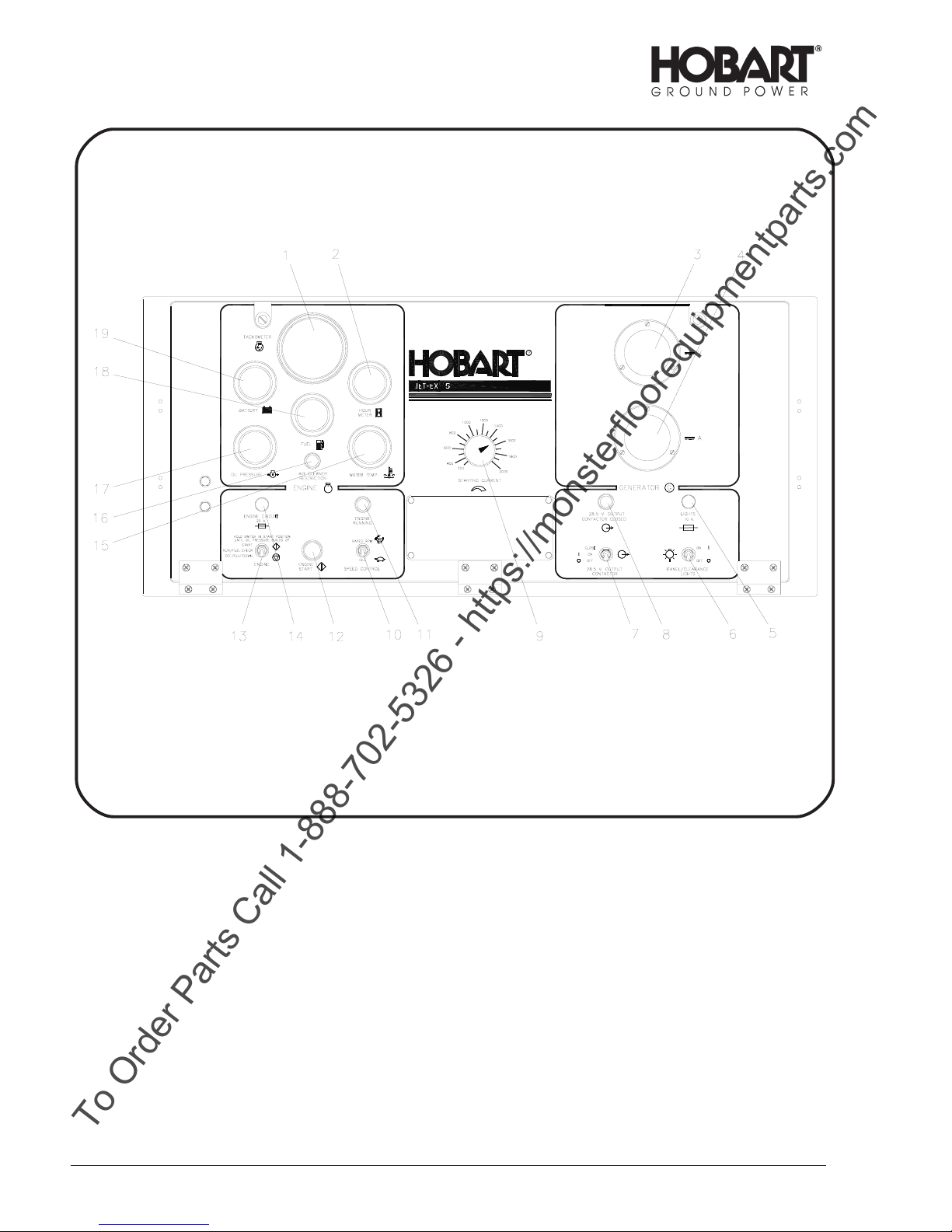
1. TACHOMETER (M403)
2. HOUR METER (M402)
3. VOLTMETER (generator) (M406)
4. AMMETER M407
5. PANEL LIGHTS FUSE (10 amp) (F401)
6. PANEL LIGHTS toggle switch (S405)
7. CONTACTOR CONTROL toggle switch (S408)
8. CONTACTOR CLOSED lamp (DS408)
9. CURRENT LIMITING CONTROL
potentiometer (R402)
10. SPEED CONTROL toggle switch (S406)
Chapter 1-1 November 1, 2000
Page 10 Revised 07/01
11. ENGINE ON lamp (DS407)
12. ENGINE START push button switch
(S401)
13. ENGINE CIRCUIT toggle switch (S404)
14. ENGINE CIRCUIT FUSE (20 Amp) (F402)
15. WATER TEMPERATURE gauge (M404)
16. AIR FILTER RESTRICTION
INDICATOR lamp (DS412)
17. OIL PRESSURE gauge (M405)
18. FUEL gauge (M408)
19. VOLTMETER (battery) (M401)
Control Box Assembly
(Front View)
Figure 5
Page 23

OM-2094 / Operation and Maintenance Manual
To Order Parts Call 1-888-702-5326 - https://monsterfloorequipmentparts.com
Jet-Ex 5D / Series 500285 / Generator Set
g. Control Box Assembly (Front) (Figure 5)
The Control Box Assembly (Figure 5) houses and provides mounting facilities for controls,
monitoring instruments, voltage regulator, relays, etc. The box is mounted at the rear of the
canopy. Its control are accessible behind a hinged plastic cover.
(1) TACHOMETER (M403)
This instrument receives its operating signal from the alternator to display the engine speed in
RPM.
(2) HOUR METER (M402)
The HOUR METER records the total hours of engine operation for scheduling maintenance.
(3) VOLT METER, generator (M406)
The VOLT METER indicates generator output voltage.
(4) AMMETER (M407)
The AMMETER displays generator current output.
(5) PANEL LIGHTS FUSE (F401)
This protects the panel lights circuit.
(6) PANEL/CLEARANCE LIGHTS toggle switch (S405)
The PANEL/CLEARANCE LIGHTS toggle switch turns the panel and clearance lamps on and
off.
(7) CONTACTOR CONTROL toggle switch (S408)
The CONTACTOR CONTROL toggle switch is a three-position toggle switch used to close and
open the output load contactor. The top CLOSE position is spring-loaded and is held
momentarily until the CONTACTOR CLOSED lamp (8) glows, then it is released to the center
ON position. In this position the switch provides holding current to the load contactor to keep it
closed. Protective devices in the load contactor circuit provide protection against over voltage by
opening the load contactor if that condition occurs. In the bottom OFF position, the contactor is
opened.
(8) CONTACTOR CLOSED lamp (DS408)
The CONTACTOR CLOSED lamp glows green when the output load contactor is closed.
(9) CURRENT LIMITING CONTROL POTENTIOMETER (R402)
The CURRENT LIMITING CONTROL POTENTIOMETER is used to select the starting current
recommended for various aircraft. The current limiting setting is continuously adjustable from
300 to 2000 amperes.
(10) SPEED CONTROL toggle switch (S406)
The SPEED CONTROL toggle switch is a two position switch wired to a throttle solenoid on the
engine. In the IDLE position, used for starting, the engine speed is controlled to approximately
1000 RPM. In the Rated RPM position, engine speed is controlled to approximately 2500 RPM.
(11) ENGINE ON lamp (DS407)
The ENGINE ON lamp glows green when the engine is running.
November 1, 2000 Chapter 1-1
Revised 07/01 Page 11
Page 24

OM-2094 / Operation and Maintenance Manual
To Order Parts Call 1-888-702-5326 - https://monsterfloorequipmentparts.com
Jet-Ex 5D / Series 500285 / Generator Set
This page intentionally left blank.
Chapter 1-1 November 1, 2000
Page 12 Revised 07/01
Page 25

OM-2094 / Operation and Maintenance Manual
To Order Parts Call 1-888-702-5326 - https://monsterfloorequipmentparts.com
Jet-Ex 5D / Series 500285 / Generator Set
(12) ENGINE START push button switch (S401)
The ENGINE START push button switch is a momentary contact switch which closes the starter
solenoid (5, Figure 3) circuit and cranks the engine. This switch is operable only when the
ENGINE CIRCUIT toggle switch (13, Figure 5) is held in its top spring-loaded START position.
(13) ENGINE CIRCUIT toggle switch (S404)
The ENGINE CIRCUIT toggle switch must be held in the top START position and the ENGINE
START push button (12) must be depressed TO START THE GENERATOR SET. When
released from its top START position after the engine starts, this toggle switch will return to
center RUN position. The ENGINE ON lamp (11) will glow as long as the switch is in RUN
position. In the bottom STOP position, this switch will stop the engine and the lamp (11) will go
out.
(14) ENGINE CIRCUIT fuse (F402)
The ENGINE CIRCUIT fuse (20 amp.) protects the engine circuitry.
(15) WATER TEMPERATURE gauge (M404)
The WATER TEMPERATURE gauge indicates the engine coolant temperature and is actuated
by a temperature sender (6, Figure 4) mounted on the engine’s water jacket.
(16) AIR FILTER RESTRICTION lamp (DS412)
The AIR FILTER RESTRICTION lamp glows red when the air filter needs changed.
(17) OIL PRESSURE gauge (M405)
The OIL PRESSURE gauge displays the pressure in the engine’s lubrication system. It is
operated by a sender (4, Figure 4) mounted on the engine block.
(18) FUEL gauge (M408)
The FUEL gauge indicates the amount of fuel remaining in the fuel tank.
(19) VOLTMETER (battery) (M401)
The battery VOLTMETER indicates the voltage of the engine’s 12 volt DC electrical system.
November 1, 2000 Chapter 1-1
Revised 07/01 Page 13
Page 26

OM-2094 / Operation and Maintenance Manual
To Order Parts Call 1-888-702-5326 - https://monsterfloorequipmentparts.com
Jet-Ex 5D / Series 500285 / Generator Set
Chapter 1-1 November 1, 2000
Page 14 Revised 07/01
1. Over voltage relay (K403)
2. Voltage regulator (VR402)
3. Excitation rectifiers (CR417 & CR418)
4. Control windings fuses (10 Amp.) (F406 - F408)
5. Voltage build-up fuse (10 Amp.) (F405)
6. Voltage regulator fuse (10 Amp.) (F403)
7. Throttle solenoid fuse (20 Amp. Slo-Blo) (F409)
8. Control Panel Lights (DS401, DS402 & DS420)
9. Rectifier Harness Connector (J43)
10. Engine Harness Connectors (J46 & J47)
11. Rectifier (CR401)
12. Capacitor (C403)
Control Box Assembly
(Interior View)
Figure 6
Page 27

OM-2094 / Operation and Maintenance Manual
To Order Parts Call 1-888-702-5326 - https://monsterfloorequipmentparts.com
Jet-Ex 5D / Series 500285 / Generator Set
h. Control Box Assembly (Interior)
Numbers in parentheses below can be crossed referenced in Figure 6
(1) Over voltage relay (K403)
The over voltage relay is a solid-state protective device on a printed circuit board. A normally
closed relay in the circuit is wired into the load contactor coil circuit. An over voltage condition
causes the relay contacts to open, which in turn prevents the contactor from closing, or opens
the load contactor and discontinues the power delivery. The over voltage module is adjusted to
trip at 32 to 34 volts DC in .5 seconds ±.2 seconds.
(2) Voltage regulator (VR402)
The voltage regulator is a solid-state device which regulates the 28.5 Volts DC generator output
after the voltage is built up.
(3) Excitation rectifiers (CR417 and CR418)
Two diode bridge rectifiers, convert an AC voltage from the generator armature to the DC
voltage needed for the generator revolving field.
(4) 3 Control Windings Fuses—cartridge-type—10 amp each (F406 - F408)
(5) Voltage Build-up Fuse—cartridge-type—10 amp (F405)
(6) Voltage Regulator Fuse—cartridge-type—10 amp (F403)
(7) Throttle Solenoid Fuse—cartridge-type—20 amp (F409)
(8) Control Panel Lights (DS401, DS402, & DS420)
Three control panel lights provide illumination for instruments and controls.
(9) Rectifier Harness Connector (J43)
Provides connections between the control box and the Rectifier assembly.
(10) Engine Harness Connectors (J46 & J47)
Provides connections between the control box and engine compartment components.
(11) Rectifier (CR401)
Automatic Voltage Build-Up.
(12) Capacitor (C403)
A 100mfd, 350V DC Capacitor, that filters the DC excitation volts produced by rectifiers CR417
and CR418.
i. EMERGENCY SHUT DOWN DEVICE
In addition to the other devices provided by the engine manufacturer, an engine shutdown feature is
added by Hobart Brothers. Since diesel engines typically require several minutes of running at idle
speed before shutdown, this push button switch is intended for use in emergencies only.
(1) EMERGENCY SHUTDOWN push button switch S413
This push button switch has one purpose: To provide immediate shut off of the generator set by
disconnecting power to the fuel solenoid through the control box. Once pushed, it must be
pulled back out to restart the generator set. It is located on the rear panel, below the control box.
To operate the EMERGENCY SHUTDOWN push button switch:
·
Push button in until engine stops or until button travel stops.
·
Pull the button back out to reset.
November 1, 2000 Chapter 1-1
Revised 07/01 Page 15
Page 28

OM-2094 / Operation and Maintenance Manual
To Order Parts Call 1-888-702-5326 - https://monsterfloorequipmentparts.com
Jet-Ex 5D / Series 500285 / Generator Set
This page intentionally left blank.
Chapter 1-1 November 1, 2000
Page 16 Revised 07/01
Page 29
OM-2094 / Operation and Maintenance Manual
To Order Parts Call 1-888-702-5326 - https://monsterfloorequipmentparts.com
Jet-Ex 5D / Series 500285 / Generator Set
Section 2. Preparation for Use, Storage or Shipping
1. Preparation for Use
a. General
The generator set is shipped with an empty fuel tank. After the fuel tank is filled and the generator
set is inspected, the generator set is ready for use.
CAUTION
Read operating instructions in Section 1-3 before operating the unit.
b. Inspection/Check
Inspect the unit completely prior to operation.
(1) Remove crating, blocking, banding, ties, and other securing and protective material.
(2) Inspect exterior for shipping damage such as broken glass, damaged sheet metal, etc.
(3) Open canopy doors and inspect interior for foreign material such as rags, tools or shipping
papers.
(4) Check the fuel and coolant systems, also the oil hoses and their connections for visible leaks. If
leaks are discovered, correct by tightening hose clamps, tube fittings, etc., as required.
(5) Check security of attaching and retaining hardware.
(6) Check the following for sufficient quantity.
a. Fuel
Fuel tank capacity is 20.5 gallons (77.6 liters).
b. Engine coolant
The radiator cap is located under the hinged door, at the front of the unit, on the top canopy.
The coolant level should be approximately one inch below the filler neck to allow for sufficient
capacity for coolant expansion.
CAUTION
Be sure the cooling system antifreeze solution is adequate to protect below
lowest temperature expected.
c. Engine lubricating oil
The oil level dipstick is located on the left side of the engine. Refer to the Engine
Manufactures User’s handbook for oil recommendations.
c. Output Cable Requirements and Installation
Jet-Ex 5D units are normally supplied with a 30ft. generator-to-aircraft output cable. This output
cable consists of two single conductor 4/0 cables.
(1) Cable requirements
·
Cable length is determined by the customer’s requirements. It is recommended that the
cable be no longer than 30 feet (9 m). It should be two conductor with lug-type terminals
on one end and an AN-2551 plug connector on the other.
November 1, 2000 Chapter 1-2
Page 1
Page 30
OM-2094 / Operation and Maintenance Manual
To Order Parts Call 1-888-702-5326 - https://monsterfloorequipmentparts.com
Jet-Ex 5D / Series 500285 / Generator Set
The recommended cable size for 28.5 volt DC is determined by the maximum starting load
·
amperage expectations. A maximum starting load of 1500 amps. requires two single
conductor 4/0 cables. A maximum starting load of 600 amps. requires two single
conductor 2/0 cables.
NOTE: Some operators may wish to add a second cable assembly with MS-25019 plug connector for
starting aircraft such as Jetstar and Sabre liner.
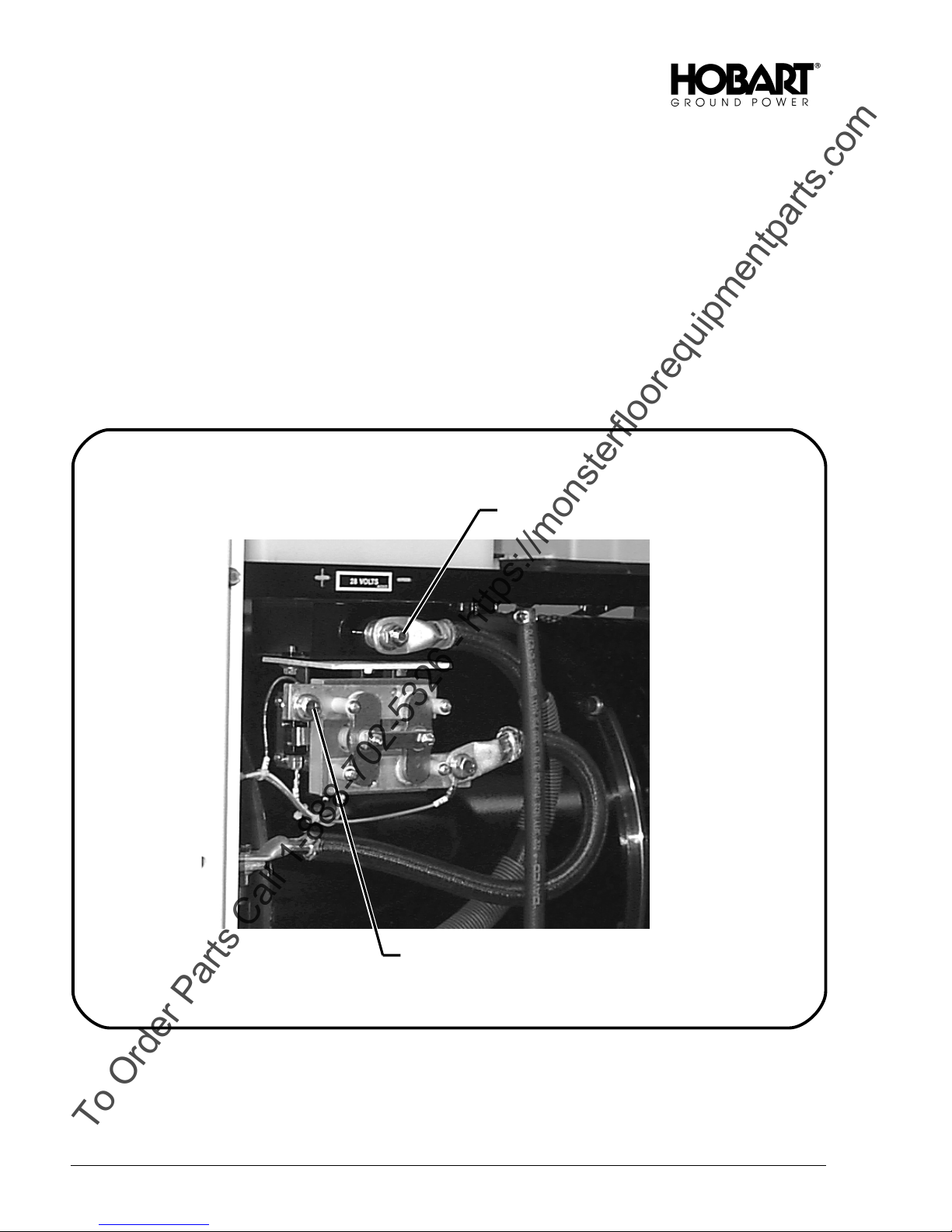
(2) Cable connection (See Figure 1)
Open and remove the right rear door and the panel below the door. Set aside.
·
Loosen the output cable clamp and thread the lugged end of the output cable through the
·
opening in the right side of the unit.
Connect the POSITIVE cable lead to the output terminal on the contactor. Connect the
·
NEGATIVE cable lead to the negative output terminal located above the load contactor.
ALWAYS place the lead under the flat washer shown.
Negative Cable Connection
Chapter 1-2 November 1, 2000
Page 2
Positive Cable Connection
Output Cable Connections
(Right Side of Unit)
Figure 1
Page 31

OM-2094 / Operation and Maintenance Manual
To Order Parts Call 1-888-702-5326 - https://monsterfloorequipmentparts.com
Jet-Ex 5D / Series 500285 / Generator Set
Tighten the cable clamp and install the lower panel, and the door.
·
Store cables in cable tray or on hangers on side of canopy if fenders are not used.
·
2.
Preparation for Storage
When a generator set is to be stored or removed from operation, special precautions should be taken
to protect the internal and external parts from rust and corrosion.
a. General
The unit should be prepared for storage as soon as possible after being removed from service.
Storage should be in a building which is dry and which may be heated during winter months.
b. Temporary Storage
When storing the unit for one month, prepare as follows:
(1) Lubricate the unit completely in accordance with instructions in Section 2-2; Para. 2. This will
include changing engine oil, and filter elements.
(2) Make certain the cooling system antifreeze solution is adequate to protect below the lowest
temperatures expected during the storage period.
(3) Clean the exterior of the engine with fuel oil and dry with clean cloths and compressed air.
(4) Seal all engine openings. Use a vapor and waterproof proof material that is strong enough to
resist puncture damage from air pressure.
c. Long Time Storage
(1) Engine Protection
The Jet-Ex 5D generator set may be stored for long periods if the engine is given proper
protection from rust and corrosion. Refer to the Engine Manufactures Users Handbook for proper
procedures to be followed.
(2) Generator Protection
To protect the generator and other electrical components, the complete unit should be
packaged, using moisture proof packaging and sealing materials. Place packages of moisture
absorbing chemicals, such as silica-gel, in the unit before packaging.
(3) Battery Care
Remove battery and store in a cool dry place. Store the battery on wood rather than directly on
cement or metal.
3.
Preparation for Shipping
Prepare the unit for shipping as follows:
·
Disconnect battery cables.
·
Seal all engine openings to prevent the entrance of water, dirt, and dust.
·
Drain all fuel from tank and fuel lines as required by carrier rules.
·
Crate the unit solidly to prevent damage to instruments, glass, and sheet metal.
November 1, 2000 Chapter 1-2
Page 3
Page 32

OM-2094 / Operation and Maintenance Manual
To Order Parts Call 1-888-702-5326 - https://monsterfloorequipmentparts.com
Jet-Ex 5D / Series 500285 / Generator Set
This page intentionally left blank.
Chapter 1-2 November 1, 2000
Page 4
Page 33

OM-2094 / Operation and Maintenance Manual
To Order Parts Call 1-888-702-5326 - https://monsterfloorequipmentparts.com
Jet-Ex 5D / Series 500285 / Generator Set
Section 3. Operation
1. General
This section contains information and instructions for the safe and efficient operation of the generator
set. Operating instructions are presented in a step-by-step sequence of procedures to be followed in
supplying power to an aircraft.
NOTE: Read ALL of the operating instructions before attempting to operate the equipment.
WARNING
Ear protection may be necessary when working close to this equipment.
Operating the Generator Set
2.
a. Pre-start Inspection
(1) Always be sure there is sufficient oil and coolant in the engine.
(2) Be sure the fuel shutoff valve is open. The valve is located at the fuel tank outlet. Observe the
fuel gage. Make certain of sufficient fuel to complete the job to be done.
(3) If the unit is trailer mounted and is not connected to a tow vehicle, be sure the parking brake is
applied and that the drawbar is raised and locked in the vertical position.
(4) Open the engine compartment doors and inspect interior for rags, tools, and foreign material.
b. Pre-start Instructions
In all probability, the unit will be moved from one location to another many times during its lifetime of
service. Therefore, the following steps should be taken to optimize maximum efficient operation.
(1) Check the supply of fuel, crankcase oil and radiator coolant. See the Engine Manufactures
User’s Manual for specifications.
(2) Inspect the unit thoroughly to be sure it is in proper working order. Check all fuel lines and wire
connections to be certain they are secure. Tighten any loose screws, nuts or bolts.
(3) Wipe off the entire unit and blowout air passages, control box, and other hard to reach places
with compressed air not over 25 psi (172 kPa).
(4) Make sure that no loose bars, tools, parts, etc., are in or on any part of the engine, as they could
cause serious damage to the engine, generator, or personal injury to anyone standing nearby.
(5) If the unit is operated indoors, make sure that an exhaust line is properly connected to the
engine exhaust system, and discharged outside. Avoid short bends or reduction in line sizes in
exhaust pipes. Locate the unit so as to necessitate the shortest possible exhaust line to insure
the least amount of back-pressure on the engine. Back-pressure can cause engine damage and
loss of power.
(6) Check the electrical system to make sure the connections are secure and properly connected.
(7) If applicabled, check the battery electrolyte level. The factory installed battery is maintenance
free.
November 1, 2000 Chapter 1-3
Page 1
Page 34

OM-2094 / Operation and Maintenance Manual
To Order Parts Call 1-888-702-5326 - https://monsterfloorequipmentparts.com
Jet-Ex 5D / Series 500285 / Generator Set
1. TACHOMETER M403
2. HOUR METER M402
3. VOLTMETER (generator) M406
4. AMMETER M407
5. PANEL LIGHTS FUSE (10 amp) F401
6. PANEL LIGHTS toggle switch S405
7. CONTACTOR CONTROL toggle switch S408
8. CONTACTOR CLOSED lamp DS408
9. CURRENT LIMITING CONTROL
potentiometer R402
10. SPEED CONTROL toggle switch S406
Chapter 1-3 November 1, 2000
Page 2
11. ENGINE ON lamp DS407
12. ENGINE START push button switch S401
13. ENGINE CIRCUIT toggle switch S404
14. ENGINE CIRCUIT FUSE (20 Amp.) F402
15. WATER TEMPERATURE gauge M404
16. AIR FILTER RESTRICTION
INDICATOR lamp DS412
17. OIL PRESSURE gauge M405
18. FUEL gauge M408
19. VOLTMETER (battery) M401
Control Box Assembly
(Front View)
Figure 1
Page 35

OM-2094 / Operation and Maintenance Manual
To Order Parts Call 1-888-702-5326 - https://monsterfloorequipmentparts.com
Jet-Ex 5D / Series 500285 / Generator Set
c. Starting The Engine (Figure 1)
Make sure that all Prestarting Instructions have been carried out, and reference to Initial Preparation
for Use has been checked for operating details.
(1) Check engine oil, fuel and coolant levels.
(2) Check AIR CLEANER SERVICE INDICATOR lamp (16, Figure 1). If lamp is glowing, replace air
filter element and/or remove other objects that obstruct air flow.
(3) Place SPEED CONTROL toggle switch (10) in the IDLE (down) position.
CAUTION
(4) Hold engine ENGINE CIRCUIT toggle switch (13) in START position.
(5) Press and hold ENGINE START push-button switch (12). Release as soon as engine starts.
(6) Release engine ENGINE CIRCUIT toggle switch (13) to RUN position when oil pressure builds
up.
(7) Observe engine RPM on the TACHOMETER (1), idle speed should be 1000 RPM +/- 50 RPM.
(8) Allow engine to warm up before applying a load.
If the engine stalls or falters in starting, wait three or four seconds before
re-engaging starter. This will prevent possible damage to starter or the engine.
DO NOT Operate the starter for periods longer than 15 seconds at a time. An
interval of at least two minutes should be allowed between cranking periods to
protect the starter from overheating.
WARNING
The engine’s entire exhaust system will get very hot and cause severe burns if
touched.
d. Generator Operation (Figure 1)
(1) Place speed control switch (10) in RATED RPM (up) position. Engine speed will be 2500 RPM,
and the generator will automatically build up to produce rated voltage.
(2) Adjust CURRENT LIMITING CONTROL potentiometer (9) if necessary. Refer to Proper Aircraft
documentation for proper setting.
e. Deliver Power
(1) Connect output cable to AIRCRAFT.
(2) Hold CONTACTOR CONTROL toggle switch (7) in CLOSE position. Release to ON position as
soon as green CONTACTOR CLOSED lamp (8) comes on.
f. Stop Operation (Shutdown)
(1) Normal Conditions
a. When power delivery is completed (aircraft discontinues drawing current), place
CONTACTOR CONTROL toggle switch (7) in OFF position. The CONTACTOR CLOSED
lamp (8) should go off to indicate load contactor has opened and power is no longer available
at the aircraft.
b. Place SPEED CONTROL toggle switch (10) in IDLE (down) position. Allow engine to run for
2 to 3 minutes.
c. Disconnect output cable from aircraft receptacle and store cable in cable trays or on cable
hangers as the case may be.
d. Place ENGINE CIRCUIT toggle switch (13) in STOP position.
November 1, 2000 Chapter 1-3
Page 3
Page 36

OM-2094 / Operation and Maintenance Manual
To Order Parts Call 1-888-702-5326 - https://monsterfloorequipmentparts.com
Jet-Ex 5D / Series 500285 / Generator Set
CAUTION
THE BATTERY WILL DRAIN if the ENGINE CIRCUIT toggle switch (13), is not
placed in STOP position after shutdown,
(2) Emergency Conditions
To prevent personal damage or damage to generator set, use of the EMERGENCY SHUT
DOWN (E-STOP) push button switch will provide immediate shut down of the engine. Once
pushed in, the E-STOP button must be pulled back out to restart the generator set.
Depress E-STOP button; engine will shut down
·
Pull E-STOP button back out to restart.
·
g. Adverse Weather Precautions
(1) Cold weather operation
Operation of this engine-driven unit at sub-zero temperatures requires special precautions and
extra servicing from both operation and maintenance personnel, if poor performance or total
functional failure is to be avoided. Consult the Engine Manufactures Maintenance and Operator’s
Manual and recommendations below.
a. Fuel system
Keep system clean and free from water which may collect in a low spot in the fuel line and
freeze, plugging the line. Fuel tanks should be kept FULL to prevent water condensation from
the air above the fuel.
b. Fuel Storage
Keep fuel storage tanks or drums as full as possible to avoid condensation of moisture from
the air above the fuel. After filling or moving fuel containers, allow fuel to settle before using.
Never draw fuel from the extreme bottom of the container. Strain all fuel to remove any
foreign matter. When operating outdoors, take steps to prevent the entry of snow, water, and
ice into the fuel containers.
c. Cooling system
Prior to cold weather, drain and flush the cooling system to remove accumulations of rust and
sediment. Mix and add antifreeze solution, check the cooling system connections for leaks.
Add a can of rust inhibitor to the radiator when system is winterized. This will keep system
cleaner and furnish lubrication for the water pump.
d. Lubrication
Drain the crankcase (preferably when warm after running) and fill with a lighter grade of oil.
See Engine Oil Recommendations chart in the Engine Manufactures User’s Manual for
recommended viscosity for various atmospheric temperatures. In cold weather, drain oil more
frequently. Water condenses and collects quickly, mixes with the oil and increases deposits
to form a sludge. Check oil frequently for this condition. Water in crankcase may freeze and
cause serious damage to the oil pump, or shut off the oil supply.
e. Electrical system
In cold weather, the most efficient electrical system is needed to start the cold engine. Check
the entire system for loose connections or indication of bad wiring or shorted conditions.
f. Battery
Battery efficiency decreases sharply with lower temperatures. Make sure of full charge before
attempting to start engine in sub-zero conditions.
Chapter 1-3 November 1, 2000
Page 4
Page 37

OM-2094 / Operation and Maintenance Manual
To Order Parts Call 1-888-702-5326 - https://monsterfloorequipmentparts.com
Jet-Ex 5D / Series 500285 / Generator Set
(2) Operation in Hot and Humid Conditions
a. Cooling system
Maintain a more frequent check of the coolant level in the radiator.
(3) Operation in Extremely Dusty Conditions
If unit is to be operated under dusty, out-of-door conditions, place it in a sheltered area. Take
advantage of any natural barriers which may offer protection from blowing dust. If the installation
is more than temporary, erect a protection shield.
a. Fuel system
Change the fuel filter at prescribed intervals and keep fuel containers covered and protected
against dust entry.
b. Air Cleaner
This filter needs more frequent attention under dusty conditions. Check Air Filter Restriction
Lamp located on control panel daily.
c. Crankcase Oil
The crankcase oil level will require close attention. Dusty conditions tend to load crankcase
oil with dirt. Watch for dirty and gritty oil conditions, and change oil more frequently as
required.
(4) Operation in Salt Water Areas
a. Canopy
Wash canopy regularly to remove salt film. Repaint any damaged places and oil the hinges
regularly.
b. Covering
To protect the engine and generator as much as possible from salt water atmosphere, keep
the side doors on the canopy closed, when not in use. It is advisable to keep the unit covered
with a tarpaulin, if available, when not in use. Salt water should be wiped from the engine,
and all terminals and connections in the electrical system wiped dry. Keep all linkage oiled.
c. Brushes
The brushes of the generator should be inspected regularly to make certain that they are free
in the holders. Lift the brushes in the brush holders about every two days to insure their
freedom to slide within the holder. Wipe dry all the parts that can be reached, and use
compressed air, if available, to dry the parts of the generator that cannot otherwise be
reached. See MAINTENANCE for brush care.
d. Field coils
The fields should be dried as thoroughly as possible. If they have become damp, proceed
with recommended procedure in MAINTENANCE section.
e. Battery terminals
Thoroughly clean the battery terminals and connections. Coat terminals and connections with
petroleum jelly to retard corrosion.
(5) Miscellaneous
Once a month, oil the hinged plexiglass cover.
November 1, 2000 Chapter 1-3
Page 5
Page 38

OM-2094 / Operation and Maintenance Manual
To Order Parts Call 1-888-702-5326 - https://monsterfloorequipmentparts.com
Jet-Ex 5D / Series 500285 / Generator Set
This page intentionally left blank.
Chapter 1-3 November 1, 2000
Page 6
Page 39

OM-2094 / Operation and Maintenance Manual
To Order Parts Call 1-888-702-5326 - https://monsterfloorequipmentparts.com
Jet-Ex 5D / Series 500285 / Generator Set
Chapter 2. Servicing / Troubleshooting
Section 1. Maintenance Inspection/Check
1. General
To make certain that generator set is always in good operating condition, it must be inspected,
maintained, and lubricated regularly and systematically.
WARNING
Stop operations at once if a serious or possibly dangerous fault is discovered.
2.
Maintenance Schedule
a. General
Figure 1 provides a suggested schedule for periodic checks and services. Refer to Section 2-2 for
lubrication requirements.
b. Maintenance Schedule Check Sheet
It is strongly recommended that the customer use a maintenance schedule check sheet. The check
sheet will provide a record of maintenance specific operation.
c. Time Intervals
The schedule is based on both hours of operation and calendar intervals. These two intervals are
not necessarily the same. The calendar period is included to make certain services are performed
regularly when equipment is being operated infrequently, or at manufacturer’s recommendations.
Perform all services on a “whichever comes first” basis.
Engine and Related Components
3.
Refer to the Engine Manufactures User’s Handbook for detailed engine maintenance information.
November 1, 2000 Chapter 2-1
Revised 03/01 Page 1
Page 40

OM-2094 / Operation and Maintenance Manual
To Order Parts Call 1-888-702-5326 - https://monsterfloorequipmentparts.com
Jet-Ex 5D / Series 500285 / Generator Set
8 hrs.
First
Service
Recommended Service Intervals
Engine
Check oil level
Check coolant level X
Check fuel quantity
Check gages and instruments for proper operation
Drain Fuel Pre-Filter Element X X
Change engine oil X X
Change oil filter X X
Check and tighten drive belts X X
Clean and inspect exterior of radiator X
Check exhaust system X
Check cooling system concentration X
Atomizer Maintenance X
Replace fuel filter X
Clean engine
Check valve tip clearance, adjust if necessary X X
Electrical System (12V DC)
Check lights X
Check charging rate X
Check battery state of charge (alternator) X
Check wiring and connections X
Check starter motor X
Check battery terminals and connectors X
Electrical system (28.5V DC)
Check indicating light
Check operation of all instruments, meters, etc. X
Check generator brushes for length, cleanliness
and free operation
Check slip rings for smoothness and cleanliness X
Check the entire unit X
Check overvoltage protection X
Check all wiring connections X
Trailer (500285-001 only)
Lubricate X
Check tire inflation X
Check and adjust wheel bearings X
Lubricate wheel bearings X
Check brake tension X
at
20/40
Hrs
or
Daily 250 hrs.
or
6 Months
X
X
X
X
X
500 hrs.
or
12
Months
2000
Hours
X
X
Inspection/Check/Maintenance Schedule
Chapter 2-1 November 1, 2000
Page 2 Revised 03/01
Figure 1
Page 41

OM-2094 / Operation and Maintenance Manual
To Order Parts Call 1-888-702-5326 - https://monsterfloorequipmentparts.com
Jet-Ex 5D / Series 500285 / Generator Set
4. Inspection and Cleaning
Every day, check for oil, coolant, or fuel leaks. Also check for loose electrical connection. Check oil
pressure with engine running at rated RPM (2500). Do not operate engine if oil pressure is less than
20 psi (138 kPA). Wipe accumulated water off from all electrical connections and instruments. Make
sure that the battery voltmeter reads proper voltage.
Every week, wipe off accumulated dust, dirt and oil from the engine and generator. Check all parts for
loose connections and wear. If arcing has occurred at any electrical connections, recondition them and
securely refasten. Check engine oil and coolant levels.
Every month, check generator for amperage and voltage output. Blow out generator windings with
compressed air, not over 25 psi (172 kPa) pressure or remove with a suction-type cleaner with a
non-metallic nozzle. If windings should become slightly damp, use space heaters or electrical light
bulbs to effectively dry out the windings. If dampness is excessive, apply external heat under a canvas
cover, well vented. Heating should not exceed 194º F (90º C).
Pound out any dents in the canopy. Sand, prime, and repaint any dented or rusted spots.
November 1, 2000 Chapter 2-1
Revised 03/01 Page 3
Page 42

OM-2094 / Operation and Maintenance Manual
To Order Parts Call 1-888-702-5326 - https://monsterfloorequipmentparts.com
Jet-Ex 5D / Series 500285 / Generator Set
This page intentionally left blank
Chapter 2-1 November 1, 2000
Page 4 Revised 03/01
Page 43

OM-2094 / Operation and Maintenance Manual
To Order Parts Call 1-888-702-5326 - https://monsterfloorequipmentparts.com
Jet-Ex 5D / Series 500285/ Generator Set
Section 2. Maintenance Procedures
1. General
A suggested Maintenance Schedule is provided in Section 1 of this Chapter. Each step of the schedule
is also covered in general in Section 1. This Section covers maintenance in more detail where
necessary.
WARNING
Stop operation immediately if a serious or possibly dangerous fault is
discovered.
Lubrication
2.
a. General
Proper lubrication is one of the most important steps in good maintenance procedure. Proper
lubrication means the use of correct lubricants and adherence to a maintenance time schedule.
Lubrication points, frequency of lubrication, and recommended lubricants are part of the time
schedule.
b. Lubrication Chart
Lubrication points are illustrated and identified by name on Lubrication Chart, Figure 1. Number
symbols used to designate the kind of lubricant required and the specification recommended are
identified in Figure 2. Letter symbols used to designate the normal lubrication period are identified in
Figure 3.
c. Generator
The 28.5 volt DC generator requires NO lubrication. The armature is sealed at the factory for
lifetime, maintenance free operation. The front end of the armature is supported by the engine main
bearings.
d. Generator Controls
Generator controls and instruments require no periodic lubrication. A few drops of oil may be
required on the clear plexiglass cover hinge occasionally to insure free and quiet operation.
e. Engine
Although the engine and its accessories require no more attention than any other similar installation,
they still inherently require a major portion of the generator set lubrication and maintenance.
Recommendations regarding engine lubrication have been taken from the Engine Manufacturers
Users Manual.
(1) Lubrication Schedule
Time schedules indicated on the Lubrication Chart, Figure 1, are approximate. They are based
on average operating conditions. It may be necessary to lubricate more frequently under severe
operating conditions such as: low engine temperature, high oil temperature, intermittent
operation, or dusty conditions. However, time intervals should not exceed those indicated in the
chart without careful evaluation.
The use of quality lubricating oil, combined with proper oil drain and filter change intervals are
important factors in extending engine life.
(2) Oil Specification
Lubricating oils must be equal to the U.S. Ordnance specification MIL-L-46152 or MIL-L-2104C.
See Engine Manufactures user’s handbook for recommended oil viscosity.
November 1, 2000 Chapter 2-2
Revised 08/01 Page 1
Page 44

OM-2094 / Operation and Maintenance Manual
To Order Parts Call 1-888-702-5326 - https://monsterfloorequipmentparts.com
Jet-Ex 5D / Spec. 7500285/ Generator Set
Check oil daily
Check crankcase oil daily; change 200 hours.
Change oil filter after 200 hours.
Chapter 2-2 November 1, 2000
Page 2 Revised 08/01
Lubrication Chart
Figure 1
Page 45

OM-2094 / Operation and Maintenance Manual
To Order Parts Call 1-888-702-5326 - https://monsterfloorequipmentparts.com
Jet-Ex 5D / Series 500285/ Generator Set
Symbol Name Specification Notes
1
2
3
Grease, Automotive and
Industrial
Oil, Engine, Heavy Duty MIL-L-46152 or
Grease, Automotive Military MIL-G-10924B Wheel bearings
Symbol Time Interval
D 10 hours or Daily
BW 100 hours or Biweekly
M 200 hours or Monthly
BM 400 hours or Bimonthly
SA 800 hours or Semiannually
Federal VV-G-632 Sinclair LItholene Industrial
No.2; Mobile-Mobilplex 47 or
equivalent.
See Cummins Engine
MIL-L-2104C
Lubricants
Figure 2
User’s Handbook for
recommended oil viscosity
Symbols and Time Intervals
Figure 3
(3) Change lubrication engine oil
Oil should be changed once after the first 20/40 hours of operation and then once every 250
hours of operation thereafter. The generator set is equipped with an hourmeter which records
actual engine operating time. The ideal time to change oil is soon after a power delivery run
when the engine is at operating temperature.
NOTE: If lubricating oil is drained immediately after the unit has been run for some time, most of the
sediment will be in suspension and oil will drain readily without clinging to internal surfaces.
CAUTION
DO NOT use solvents as flushing oils in running engines.
NOTE: Change the oil filter each time the oil is changed (250 hours).
(4) Change oil as follows:
a. Provide a container for catching used oil. Capacity should be greater than 2 gallons.
b. Remove drain plug located in oil pan. Allow sufficient time for oil to drain from valve train,
timing gear case, etc., before reinstalling plug.
NOTE: Change oil filter while oil is draining.
Change oil filter as follows:
c. Place a container under the oil filter to catch oil drippings.
d. Loosen filter with a special oil filter removal wrench. Several types are available. Discard oil
filter.
e. Coat the gasket on the new filter with oil.
f. Place the new filter in position on the cylinder block and spin on until the gasket contacts the
adapter face; then hand tighten another 1/2 turn. Do not over-tighten.
g. Clean drain plug and reinstall. DO NOT over-tighten.
November 1, 2000 Chapter 2-2
Revised 08/01 Page 3
Page 46

OM-2094 / Operation and Maintenance Manual
To Order Parts Call 1-888-702-5326 - https://monsterfloorequipmentparts.com
Jet-Ex 5D / Spec. 7500285/ Generator Set
h. Remove filler cap on valve cover and refill crankcase with fresh clean oil, of proper
specification and viscosity (see Para. 2, E, (2) and Figure 2). Seven quarts are required when
oil filter is changed.
i. Replace oil filler cap.
j. Start engine and allow it to idle. Oil pressure should come up to normal quickly. Check for oil
leaks at filter and drain plug.
k. Stop engine. Allow several minutes for oil to drain to crankcase, then check oil level. It should
be at FULL mark on dipstick.
l. Check hourmeter and record time and date of oil change for maintenance reasons..
3.
Servicing the Air Cleaner
The air cleaner is a dry type with a “C” flow cartridge. A definite time schedule for changing the filter
cartridge cannot be determined because of varying operating conditions, therefore an air restriction
indicator lamp (Sect. 1-3; 16, Figure 1) is mounted on the control panel. Change the filter when the red
indicator lamp glows.
a. Cartridge Removal
(1) Open right rear canopy door to gain access to the air cleaner.
(2) Using a 5/16 socket, loosen the clamps which surround the air cleaner and secure it to the air
filter bracket.
(3) Loosen and remove the clamp and air cleaner from the intake hose.
CAUTION
DO NOT attempt to clean or re-use old cartridge.
b. Cartridge Installation
(1) Attach the new air filter cartridge to the intake hose and tighten the clamp.
(2) Secure the air filter cartridge to the air filter bracket with the same two large clamps. DO NOT
over-tighten.
Servicing the Fuel Filter
4.
Refer to the Engine Manufacturers User’s Handbook for instructions on removal and replacement of
fuel filter elements.
5.
Drive Belt Service
Check all drive belts and adjust if necessary each 250 hours. Refer to Engine Manufacturers User’s
Manual for proper procedures.
6.
Engine Cooling System
NOTE: Refer to the Engine Manufacturers User’s Manual for detailed instructions on servicing the engine’s
cooling system.
In all weather situations, the engine coolant should always contain a solution of 50% water and 50%
antifreeze (ethylene glycol). Rust inhibitors are recommended in the coolant as rust corrosion can still
occur.
WARNING
Never remove the cap from a hot radiator. The radiator cap should not be
removed unless the engine temperature is 140º F (60º C) or below.
Chapter 2-2 November 1, 2000
Page 4 Revised 08/01
Page 47

OM-2094 / Operation and Maintenance Manual
To Order Parts Call 1-888-702-5326 - https://monsterfloorequipmentparts.com
Jet-Ex 5D / Series 500285/ Generator Set
a. Radiator Cap Removal
Cover the cap with a thick cloth and turn it slowly counterclockwise to the first stop. When pressure
is completely released, press downward and finish removing cap.
CAUTION
b. Rust Inhibitor
Use only a corrosion inhibitor that is compatible with aluminum. Do not use inhibitors labeled as
“acid neutralizer.”
c. Antifreeze
A permanent type (Ethylene Glycol) antifreeze is recommended for use in the cooling system. The
coolant, when mixed as equal parts of water and the recommended antifreeze, will provide
protection to -35º F.
Battery Service
7.
a. General
A 12-volt battery supplies power for operation of the engine electrical system, clearance and panel
lights, and for building up generator voltage. The battery supplied with a new unit is a maintenance
free type. Some of the following topics apply to non-maintenance free type battery, which requires
additional maintenance such as checking liquid levels.
b. Battery Location and Accessibility
The battery is located on a tray mounted to the left front frame. The battery is easily accessible for
service by opening the left front door and removing the lower panel below the door.
c. Battery Care
(1) Never allow a battery which has been removed from a unit to sit on concrete, ground, or metal,
unless proper insulation is provided. A wooden platform or board will provide sufficient insulation.
(2) Maintain stored batteries in a charged condition,
(3) Be sure battery is fastened securely in their compartment to avoid damage from vibration.
(4) If applicable, maintain battery fluid at proper level (see below).
(5) Keep battery terminal posts and lead cable connectors clean.
DO NOT add coolant to an extremely hot engine. This can result in a cracked
block or cylinder head.
WARNING
Never allow sparks or open flame near battery. Avoid spilling electrolyte on
hands or clothing.
d. Liquid Level (If battery is not a maintenance free type)
The electrolyte in each cell should be above the plates at all times to prevent battery failure.
Check the level of the electrolyte every two weeks. When electrolyte level is low, add pure
distilled water. Do not use hydrant water or any water which has been in contact with a metal
container. Acid should never be added except by skilled battery personal.
CAUTION
Never add any special battery dopes, solutions, or powders.
NOTE: It is especially important to keep the battery at full charge for cold weather operation. Add distilled water
to the battery in freezing temperatures only when the engine is to operate for several hours. Thoroughly
November 1, 2000 Chapter 2-2
Revised 08/01 Page 5
Page 48

OM-2094 / Operation and Maintenance Manual
To Order Parts Call 1-888-702-5326 - https://monsterfloorequipmentparts.com
Jet-Ex 5D / Spec. 7500285/ Generator Set
mix the water and the electrolyte, or damage to the battery will result from the water freezing.
e. Cleaning the Battery
If the top of the battery is dirty, it may be cleaned with a brush dipped in ammonia or soda solution.
Disconnect lead connectors from battery posts. Vent plugs should be tightened to prevent cleaning
solution from entering cells. Clean battery as required, using brush and cleaning solution. Flush off
the battery with clean water. Special terminal cleaning tool. Make certain that vent holes in filler
caps are not clogged.
f. Testing a Battery
Tests are made on a battery to determine the state of charge and also its condition. The results of
these tests show whether the battery is good, needs recharging, or must be replaced. If a battery
has failed, is low in charge, or requires water frequently, the reason for the condition must be found
and corrected. Visually inspect the battery before testing, to determine if it has been damaged.
Moisture on the outside of the case, or low fluid level in one or more cells indicates possible battery
damage (cracked case, etc.). The battery may be tested by two methods. A battery-starter tester
may be used to determine the battery’s ability to deliver current. A battery hydrometer test
determines the charge condition of the battery.
(1) Battery-Starter Tester
Connect battery to the tester according to instructions furnished with the instrument. Test
battery according to tester instructions. If the test determines that the battery has acceptable
voltage, this indicates that the battery has output capacity and will accept a charge if required.
(2) Hydrometer
Remove filler caps and check the specific gravity of the electrolyte in each cell. If specific gravity
is 1.230 or below, add water if necessary and charge the battery until it is fully charged. A fully
charged battery will give a specific gravity reading of 1.265 to 1.285. The specific gravity of a
fully discharged battery may range from 1.140 down to 1.120.
NOTE: The battery is fully charged when all cells are gassing freely, and the specific gravity ceases to
rise for three successive readings taken at hourly intervals.
a. If the battery starter test indicated that battery voltage was below the acceptable voltage
value, test each cell with the hydrometer. If the difference in specific gravity readings between
any two cells is 50 points (0.050) or more, the battery isn’t satisfactory for service and should
be replaced.
A-Leads
B-Brusholder Caps
Generator Revolving Field Brushes
Figure 4
C-Brusholder
Chapter 2-2 November 1, 2000
Page 6 Revised 08/01
D-Brush
E-Slip Rings
Page 49

OM-2094 / Operation and Maintenance Manual
To Order Parts Call 1-888-702-5326 - https://monsterfloorequipmentparts.com
Jet-Ex 5D / Series 500285/ Generator Set
8. Generator Maintenance
a. General
The only maintenance service required for the generator will be brush replacement, slip ring
cleaning, etc.
b. Brush Service
If inspection reveals that brushes are gummy or sticking in the brush holders, they should be
removed and cleaned. Clean both the brushes and brush holders. Use a good, SAFE, commercial
cleaner.
DRY ALL PARTS THOROUGHLY. Be sure brushes can move freely in brush holders.
CAUTION
DO NOT use a flammable solvent. DO NOT use steam cleaner, or soaps and
detergents under pressure.
c. Generator Revolving Field Brush Replacement (See Figure 4)
(1) Disconnect leads (A, Fig. 4) from connectors on brush holder caps (B).
(2) Remvoe brush holder caps (B) from brusholder.
WARNING
(3) Lift brush (D) from brush holder (C) for inspection. If brushes are worn unevenly or are shorter
than 7/16 inch (11 mm), replace them.
(4) Inspect slip rings whenever brushes are removed for servicing brushes or brush holders. Note
surface conditions of rings. Surface should appear smooth and clean. Scoring or roughness of
slip rings may be caused by grit or abrasive substance in brushes, or by oil on the rings.
Moderately rough slip rings can be smoothed by holding grade 00 flint paper against their
surface while the rings are revolving slowly. If the rings are badly scored, the unit must be sent
to an overhaul facility for repair. After cleaning slip rings, blow dirt and grit out of the unit with
compressed air. Do not use over 25 psi (172 kPa) air pressure to blow dirt out.
(5) Slip new brushes into brush-holder guides, and place caps on top, and screw them into the
guides to a “bottomed” position. The spring attached to the brush will determine the pressure at
which the brush contacts the slip rings.
(6) To fit new brushes to the slip rings, lay a strip of No. 00 sand- paper, smooth side down, on slip
ring surface, and draw the sandpaper in the direction of rotation of the slip ring, lifting the brush
on the return stroke. Continue until the brushes have same curvature as the slip rings. Blow all
carbon dust out of the machine using not over 25 psi (172 kPa) air pressure.
When removing the lead wires, do so one at a time and replace each brush
accordingly, to insure that the lead wires are put pack onto the proper brushes.
November 1, 2000 Chapter 2-2
Revised 08/01 Page 7
Page 50

OM-2094 / Operation and Maintenance Manual
To Order Parts Call 1-888-702-5326 - https://monsterfloorequipmentparts.com
Jet-Ex 5D / Spec. 7500285/ Generator Set
This page intentionally left blank.
Chapter 2-2 November 1, 2000
Page 8 Revised 08/01
Page 51

OM-2094 / Operation and Maintenance Manual
To Order Parts Call 1-888-702-5326 - https://monsterfloorequipmentparts.com
Jet-Ex 5D / Series 500285 / Generator Set
Section 3. Adjustment/Test
1. General
The adjustments and test procedures presented below are required after major repairs, parts
replacement, or long storage.
2.
Testing the Generator Set
Test values listed below will result when the generator set is operating properly. If your test results are
not within the limits shown, perform the applicable troubleshooting procedures given in Chapter 3.
If major repairs have been made or if critical components have been replaced, make sure that the
applicable adjustments have been made before testing the generator set. Adjustment procedures are
described in Para. 3 of this Section.
a. Pre-operational Test Procedures
(1) Open engine compartment doors and inspect the interior for rags, tools, and other foreign
materials.
(2) Check engine oil level.
(3) Check coolant level.
(4) Check battery water level (if required)
(5) Check for sufficient fuel.
(6) Check drive belts. Each belt should have approximately 1/2 inch (13 mm) slack.
(7) Inspect all wiring for possible trouble spots such as loose wires or terminals, frayed insulation,
obvious shorts, etc.
(8) Check panel lights, panel light switch, and fuse.
(9) Connect cables from generator output terminals to a load bank. The output cable consists of two
single conductor cables not more than 30 feet (9 m) long. The diameter size of each of these
two cables is determined by the maximum starting current expectations:
·
Use No. 2/0 cable for 600 amp. maximum starting current
·
Use No. 4/0 cable for 1500 amp. maximum starting current.
November 1, 2000 Chapter 2-3
Revised 07/01 Page 1
Page 52

OM-2094 / Operation and Maintenance Manual
To Order Parts Call 1-888-702-5326 - https://monsterfloorequipmentparts.com
Jet-Ex 5D / Series 500285 / Generator Set
1. TACHOMETER M403
2. HOUR METER M402
3. VOLTMETER (generator) M406
4. AMMETER M407
5. PANEL LIGHTS FUSE (10 amp) F401
6. PANEL LIGHTS toggle switch S405
7. CONTACTOR CONTROL toggle switch S408
8. CONTACTOR CLOSED lamp DS408
9. CURRENT LIMITING CONTROL
potentiometer R402
10. SPEED CONTROL toggle switch S406
Chapter 2-3 November 1, 2000
Page 2 Revised 07/01
11. ENGINE ON lamp DS407
12. ENGINE START push button switch S401
13. ENGINE CIRCUIT toggle switch S404
14. ENGINE CIRCUIT FUSE (20 Amp.) F402
15. WATER TEMPERATURE gauge M404
16. AIR FILTER RESTRICTION
INDICATOR lamp DS412
17. OIL PRESSURE gauge M405
18. FUEL gauge M408
19. VOLTMETER (battery) M401
Control Box Assembly
(Front View)
Figure 1
Page 53

OM-2094 / Operation and Maintenance Manual
To Order Parts Call 1-888-702-5326 - https://monsterfloorequipmentparts.com
Jet-Ex 5D / Series 500285 / Generator Set
b. Operational Tests (Figure 1)
(1) Start the engine as described in 1-3; Para. 2, and let it warm at idle speed.
(2) Inspect for oil, fuel, and coolant leaks.
(3) Check the engine VOLTMETER (19) for proper voltage. Check OIL PRESSURE gauge (17). It
should read 35 to 60 psi (241 to 414 kPa). Check WATER TEMPERATURE gauge (15). It
should read 180 to 200º F (82 to 93º C.) when engine is hot.
(4) Observe engine RPM on the TACHOMETER (1), idle speed should be 1000 RPM ± 50 RPM.
(5) Place the SPEED CONTROL switch (10) in the RATED RPM position. Check engine RPM’s at
operating speed: 2500 RPM ±50
(6) Check for 28.5 output voltage on generator VOLTMETER (3) to assure automatic voltage
buildup.
(7) Set CURRENT LIMITING CONTROL potentiometer (9) to maximum, full clockwise, position.
(8) Adjust the load bank for a load of 550 amperes.
(9) Place the CONTACTOR CONTROL toggle switch (7) in the CLOSE position. The CONTACTOR
CLOSED lamp (8) will glow as the contactor will close. Release the CONTACTOR CONTROL
toggle switch to the center ON position. The TACHOMETER (1) will indicate 2200 ± 25 RPM.
(10) Disconnect the load bank and check the overvoltage protection by adjusting voltage regulator
potentiometer R46 (1, Fig. 2) to increase the voltage. The overvoltage relay will trip and open the
load contactor between 32 to 34 volts.
(11) Readjust the voltage to 28.5 volts, connect the load bank, set it at 550 amperes, and close the
contactor.
(12) Remove load bank and check voltage regulation at no load. Voltage will be 28.5 volts.
Reconnect load bank and check voltage regulation with load bank set at 137, 275, 413, 550, and
660 amperes and check voltage at each setting. Voltage will be 28.5 ± 1 volts at each different
load.
(13) With CURRENT LIMITING CONTROL potentiometer (9) set to 2000, apply 600 to 700 amperes
load to the generator and then set the CURRENT LIMITING CONTROL potentiometer to 400.
Current displayed on AMMETER (4) will be 400 ± 40 amperes.
NOTE: Voltage will not drop below 14 volts.
(14) Set CURRENT LIMITING CONTROL potentiometer (9) to 2000 and apply 1200 amperes load.
Then set the CURRENT LIMITING CONTROL potentiometer to1000. Current displayed on
AMMETER (4) will then be 1000 ± 100 amperes and voltage will not drop
(15) Remove load. Set engine to idle. Run for 3 minuets at idle
(16) Stop and restart the engine, check the instruments as directed in step (3), and check the entire
generator set for unusual vibration and noises.
November 1, 2000 Chapter 2-3
Revised 07/01 Page 3
Page 54

OM-2094 / Operation and Maintenance Manual
To Order Parts Call 1-888-702-5326 - https://monsterfloorequipmentparts.com
Jet-Ex 5D / Series 500285 / Generator Set
3. Voltage Regulator Adjustment
a. 28.5 Volt Adjustment
(1) The regulating voltage, in the 28.5 volt range, is determined by the position of the wiper arm of
the multi-turn potentiometer (1,Figure 2) R46. Clockwise (CW) rotation increases the voltage
level at which the unit operates. Conversely, counterclockwise (CCW) rotation decreases the
voltage level.
b. Line Drop Compensation
(1) Line drop compensation allows the voltage at the load end of the output cable to remain constant
despite the voltage drop associated with the output cable. Clockwise (CW) rotation of the
single-turn potentiometer (2,Figure 2) R24 increases the compensation. This potentiometer
should be set for flat regulation of voltage at the load end of the output cable when delivering
rated load current.
Voltage and Line Drop Adjustments
Chapter 2-3 November 1, 2000
Page 4 Revised 07/01
Figure 2
Page 55

OM-2094 / Operation and Maintenance Manual
To Order Parts Call 1-888-702-5326 - https://monsterfloorequipmentparts.com
Jet-Ex 5D / Series 500285 / Generator Set
Section 4. Troubleshooting Procedures
1. General
Troubleshooting is an orderly process of checking and eliminating possible causes of trouble until the
exact cause of a trouble is found. As a rule, the best place to start looking for the cause of a trouble in a
circuit is at the source of power. Continue testing and checking the circuit, step-by-step, in an orderly
manner, until the cause of trouble is located. Reference connection and schematic diagrams.
2.
Troubleshooting Chart
a. Description
The troubleshooting chart lists information under three headings:
(1) Trouble, Symptom, and Condition,
(2) Probable Cause
(3) Test, Check, and Remedy
b. Use of the Troubleshooting Chart
Read the trouble symptoms and conditions before proceeding to causes and remedies.
For example:
At the beginning of the troubleshooting chart under ENGINE, the first trouble listed is: “Engine
will not start. Starter will NOT crank engine.”
If the starter WILL crank the engine, then obviously this is not your symptom and condition. Go to
the next “Trouble, Symptom, and Condition” directly below. If the starter will NOT crank the engine,
look to the right under “Probable Cause” and “Test, Check, and Remedy” to find the various things
which could cause the trouble and what to do to check and remedy them.
Equipment for Troubleshooting
3.
A good quality, multi-scale voltmeter is the only instrument required similar clips, will be required. The
12 volt engine electrical system may be used for a 12 volt DC power source.
4.
Safety Precautions
WARNING
5.
Diagrams
A schematic/connection diagram of the generator set is provided in Chapter 5. This diagram can be
very helpful in troubleshooting. Components shown in the diagram are identified by reference
designators (or item names in some instances). A legend appearing on the diagram identifies each
reference designator by its full item name. For example, the symbol K403 identifies the overvoltage
relay, and M406 identifies the voltmeter.
6.
Connections and Wiring
Before condemning any electrical component, check all connections and wiring which could affect its
operation. In many instances a component may be non-functional simply because it is not receiving
power because of a loose connection or a poor ground. In most cases throughout the troubleshooting
chart, it will be assumed that connections and wiring have been checked.
Loose garments, neckties, and other hanging items must not be worn by
personnel near the fan or other exposed moving parts of this equipment while it
is running. Also, avoid contact with live electrical parts. death or serious injury
could result!
November 1, 2000 Chapter 2-4
Revised 07/01 Page 1
Page 56

OM-2094 / Operation and Maintenance Manual
To Order Parts Call 1-888-702-5326 - https://monsterfloorequipmentparts.com
Jet-Ex 5D / Series 500285 / Generator Set
27 1
3
1. Fuel Tank Support
2. Fuel Tank
3. Control Panel
4. Rectifier Assembly
5. Generator
9
6
5
4
8
6. Frame
7. Engine
8. Air Cleaner
9. Battery
10. Contactor
Chapter 2-4 November 1, 2000
Page 2 Revised 07/01
Generator Set Components
Figure 1
Page 57

OM-2094 / Operation and Maintenance Manual
To Order Parts Call 1-888-702-5326 - https://monsterfloorequipmentparts.com
Jet-Ex 5D / Series 500285 / Generator Set
5
4
1
3
2
1. Muffler
2. Alternator
3. Oil filter
4. Starter
5. Starter solenoid
Engine Comp[onents
(Right Side of Unit)
Figure 2
November 1, 2000 Chapter 2-4
Revised 07/01 Page 3
Page 58

OM-2094 / Operation and Maintenance Manual
To Order Parts Call 1-888-702-5326 - https://monsterfloorequipmentparts.com
Jet-Ex 5D / Series 500285 / Generator Set
267
1
3
1. Fuel filter
2. Air cleaner
3. Throttle control assembly
4. Oil pressure sender
5. Oil pressure switch 20 psi (138 kPA)
6. Water Temp. Sender
7. Radiator
4
5
Chapter 2-4 November 1, 2000
Page 4 Revised 07/01
Engine Components
(Left Side of Unit)
Figure 3
Page 59

OM-2094 / Operation and Maintenance Manual
To Order Parts Call 1-888-702-5326 - https://monsterfloorequipmentparts.com
Jet-Ex 5D / Series 500285 / Generator Set
1. TACHOMETER (M403)
2. HOUR METER (M402)
3. VOLTMETER (generator) (M406)
4. AMMETER (generator) (M407)
5. PANEL LIGHTS FUSE (10 amp) (F401)
6. PANEL LIGHTS toggle switch (S405)
7. CONTACTOR CONTROL toggle
switch (S408)
8. CONTACTOR CLOSED lamp (DS408)
9. CURRENT LIMITING CONTROL
potentiometer (R402)
10. SPEED CONTROL toggle switch
(S406)
November 1, 2000 Chapter 2-4
Revised 07/01 Page 5
11. ENGINE ON lamp (DS407)
12. ENGINE START push button switch (S401)
13. ENGINE CIRCUIT toggle switch (S404)
14. ENGINE CIRCUIT FUSE (20 Amp.) (F402)
15. WATER TEMPERATURE gauge (M404)
16. AIR FILTER RESTRICTION
INDICATOR lamp (DS412)
17. OIL PRESSURE gauge (M405)
18. FUEL gauge (M408)
19. VOLTMETER (battery) (M401)
Control Box Assembly
(Front View)
Figure 4
Page 60

OM-2094 / Operation and Maintenance Manual
To Order Parts Call 1-888-702-5326 - https://monsterfloorequipmentparts.com
Jet-Ex 5D / Series 500285 / Generator Set
Chapter 2-4 November 1, 2000
Page 6 Revised 07/01
1. Over voltage relay (K403)
2. Voltage regulator (VR402)
3. Excitation rectifiers (CR417 & CR418)
4. Control windings fuses (10 Amp.) (F406 - F408)
5. Voltage build-up fuse (10 Amp.) (F405)
6. Voltage regulator fuse (10 Amp.) (F403)
7. Throttle solenoid fuse (20 Amp. Slo-Blo) (F409)
8. Control Panel Lights (DS401, DS402 & DS420)
9. Rectifier Harness Connector (J43)
10. Engine Harness Connectors (J46 & J47)
11. Rectifier (CR401)
12. Capacitor (C403)
Control Box Assembly
(Interior View)
Figure 5
Page 61

OM-2094 / Operation and Maintenance Manual
To Order Parts Call 1-888-702-5326 - https://monsterfloorequipmentparts.com
Jet-Ex 5D / Series 500285 / Generator Set
Section 5. Troubleshooting Charts
See section 2-4 for all figures referenced in this section.
Engine and Controls
Trouble, Symptom and Condition Probable Cause Test, Check, and Remedy
1. Engine will not start. Starter
will not crank engine.
a. Batteries discharged, sure
this voltage is reaching or
loose battery or ground
connection.
b. ENGINE START push
button switch S401
(12, Figure 4) defective.
c. Defective starter solenoid
L401 (5, Figure 2)
d. Defective starter B401
(4, Figure 2)
Check battery connections and
check voltage across battery.
Voltage should be approximately
12.8 VDC. If battery and
connections are good, proceed
to the next step.
Momentarily connect a jumper
between the hot side of the
starter solenoid L401 and the
start switch terminal on the
starter relay wire. If the starter
operates, replace faulty switch.
If starter doesn’t crank, proceed
to the next step.
Momentarily connect a large
capacity jumper cable between
the hot side of the starter relay
(Figure 2) and the starter input
terminal. If the starter attempts
to crank the engine, the starter
solenoid is defective. Replace
it. If engine still won’t crank,
proceed to the next step.
If the engine will not crank after
the previous steps, the starter is
defective. Replace starter. If
starter did attempt to operate,
but couldn’t turn engine,
proceed to the next step.
November 1, 2000 Chapter 2-5
Revised 03/01 Page 1
e. Internal engine seizure.
CAUTION:
Make certain that engine start
switch is in “stop” position so
that engine does not start.
Use a socket wrench on the front
crankshaft pulley to try to turn
engine by hand. If engine will
not turn, internal damage is
indicated.
Page 62

OM-2094 / Operation and Maintenance Manual
To Order Parts Call 1-888-702-5326 - https://monsterfloorequipmentparts.com
Jet-Ex 5D / Series 500285 / Generator Set
Engine and Controls (continued)
See section 2-4 for all figures referenced in this section.
Trouble, Symptom and Condition Probable Cause Test, Check, and Remedy
Engine will not start. Starter
will not crank engine
(continued).
2. Engine will not start. Starter
DOES crank engine.
f. Engine seized up NOTE:
If engine is overcharged
with ether for cold weather
starting, it could seize up. If so,
wait approx. 1/2 hour until it will
be possible to turn engine.
a. ENGINE CIRCUIT FUSE
F402 (14, Figure 4) blown
b. Fuel valve at tank closed, or
no fuel in tank, engine has
lost its prime
c. Defective ENGINE
CIRCUIT toggle switch
S404 (13, Figure 4)
d. Defective fuel valve
solenoid (L404).
e. Defective fuel pump.
Replace ENGINE CIRCUIT
FUSE. Use type AGC-2O fuse.
Check and correct as required.
Check for 12-V DC from
terminal 4 of S404 in “START”
position. If 12-V DC is not
measured, replace defective
switch.
Attempt to start engine while
applying 12-V DC to the fuel
valve solenoid. If the engine
starts, the solenoid is defective,
and should be replaced. If
engine still doesn’t start,
proceed to next step.
Check fuel pump according to
instructions in the Engine
Manufactures User’s Manual.
3. Engine starts then stops. a. Fuel not turned on.
Chapter 2-5 November 1, 2000
Page 2 Revised 03/01
b. Defective oil pressure
switch S403 (5, Figure 3)
Turn on fuel shutoff valve.
Connect a jumper wire across
the “C” and “N.O.” terminals of
oil pressure switch. Start engine
and check oil pressure. If it is
below 10 PSI (69 kPa) shut
down the engine and check
lubrication system for leaks.
Also check the oil pump for
leaks. If oil pressure comes up
to normal and the engine
continues to run, the oil
pressure switch is defective.
Replace oil pressure switch.
Page 63

OM-2094 / Operation and Maintenance Manual
To Order Parts Call 1-888-702-5326 - https://monsterfloorequipmentparts.com
Jet-Ex 5D / Series 500285 / Generator Set
Engine and Controls (continued)
See section 2-4 for all figures referenced in this section.
Trouble, Symptom and Condition Probable Cause Test, Check, and Remedy
4. Engine starts then stops when
ENGINE CIRCUIT toggle
switch S404 is released to
“ON” position.
5. Engine does not attain normal
idle RPM, or idles too fast.
a. Open over temperature
switch S402 or defective
ENGINE CIRCUIT toggle
switch.
b. Choked fuel filter, restriction
in air cleaner, or air in fuel
system.
a. Loose throttle linkage
b. Defective full throttle
solenoid L403.
Place a clip-lead jumper wire on
the water temperature switch
terminals and check for normal
operating temperature. If engine
then starts properly, replace
water temperature switch. If not,
replace engine switch.
Check for these faults according
to instructions in the Engine
Manufactures User’s Manual.
If solenoid core is pulled into the
full throttle solenoid L403 when
SPEED CONTROL toggle
switch S406 is in RATED RPM
position, check for loose control
rod between solenoid and
throttle. Tighten if required. If
solenoid core does not pull in,
proceed to the next step.
Check for l2-V-DC across two
terminals of solenoid when
S406 is in RATED RPM
position. If l2-V DC is measured,
but solenoid core does not pull
in, replace the solenoid.
6. Engine will not run at rated
speed (2450-2550 RPM)
November 1, 2000 Chapter 2-5
Revised 03/01 Page 3
a. SPEED CONTROL toggle
switch S406 (10, Figure 4)
defective.
If engine will not go from idle to
rated speed when SPEED
CONTROL toggle switch is in
RATED RPM position, turn off
engine and take resistance
measurements at SPEED
CONTROL toggle switch
terminals with switch in the
RATED RPM position.
Zero resistance should be
measured between terminals
having red-blue and orange
yellow wires. Replace speed
control switch if measurement is
improper.
Page 64

OM-2094 / Operation and Maintenance Manual
To Order Parts Call 1-888-702-5326 - https://monsterfloorequipmentparts.com
Jet-Ex 5D / Series 500285 / Generator Set
Engine and Controls (continued)
See section 2-4 for all figures referenced in this section.
Trouble, Symptom and Condition Probable Cause Test, Check, and Remedy
7. Engine lacks power. a. Insufficient air to engine. Check AIR FILTER
RESTRICTION INDICATOR
lamp (16, Figure 4) for
illumination. Replace or clean as
required.
b. Restricted exhaust system.
c. Low compression.
8. Engine Overheats. a. Dirt or sludge in Coolant
b. Debris and dirt in radiator
core.
c. Fan belt slips or is broken.
Check exhaust pipe for
restrictions. Check muffler for
clogged condition. Replace as
required.
Check compression in all
cylinders according to the
Engine Manufactures User’s
Manual.
Drain coolant, flush radiator, put
in clean coolant. Refer to the
Engine Manufactures User’s
Manual in for instructions.
Clean radiator core carefully.
Refer to the Engine
Manufactures User’s Manual.
Tighten belt or replace as
required
Chapter 2-5 November 1, 2000
Page 4 Revised 03/01
Page 65

OM-2094 / Operation and Maintenance Manual
To Order Parts Call 1-888-702-5326 - https://monsterfloorequipmentparts.com
Jet-Ex 5D / Series 500285 / Generator Set
Generator and Controls
See section 2-4 for all figures referenced in this section.
Trouble, Symptom and Condition Probable Cause Test, Check, and Remedy
1. Generator will not build up
voltage when SPEED
CONTROL toggle switch S406
(10, Figure 4) is placed in
RATED RPM position.
a. Voltage build-up fuse F405
is blown.
b. Defective excitation rectifier
CR417 and/or CR418.
c. Defective capacitor C403.
d. Defective flyback diode
CR419.
e. Generator revolving field
L406 defective.
Replace voltage build-up fuse
(5, Figure 5). Proceed to Step b
to determine cause of blown
fuse.
Check excitation rectifiers ( 3,
Figure 5) with an ohmmeter to
see if they are good. If either
rectifier is defective, replace it.
If both rectifiers are good,
proceed to Step c.
Check capacitor (12, Figure 5)
with an ohmmeter to see if it is
good. If defective, replace it;
otherwise proceed to Step d.
Check diode, on brushholder
mounting bracket, with an
ohmmeter to see if it is good. If
defective, replace it; otherwise
proceed to Step e.
Locate yellow and red-orange
wires on the right terminal strip
at lower rear of control panel.
Disconnect the yellow and
red-orange wires which go down
to the generator. Refer to
connection diagrams in Chapter
5.
Measure resistance between
these two wires. It should be 10
to 11 ohms. If reading indicates
an open, short or lower than
normal resistance, proceed to
Step f.
November 1, 2000 Chapter 2-5
Revised 03/01 Page 5
f. Defective generator
armature G402.
g. Voltage regulator fuse F403
is blown.
If check of the generator
revolving field (Step e. above)
revealed no trouble, the
generator stator is defective.
Send unit to overhaul.
Replace voltage regulator fuse
(6, Figure 5). Proceed to Step
h. to determine reason for blown
fuse.
Page 66

OM-2094 / Operation and Maintenance Manual
To Order Parts Call 1-888-702-5326 - https://monsterfloorequipmentparts.com
Jet-Ex 5D / Series 500285 / Generator Set
Generator and Controls (continued)
See section 2-4 for all figures referenced in this section.
Trouble, Symptom and Condition Probable Cause Test, Check, and Remedy
Generator will not build up
voltage when SPEED
CONTROL toggle switch S406
(10, Figure 4) is placed in
RATED RPM position
(continued)
2. Generator builds up to only a
low voltage when SPEED
CONTROL toggle switch S406
(10, Figure 4) is place in
RATED RPM position
3. Generator builds too high a
voltage.
h. Defective rectifier CR401. Use ohmmeter to check rectifier
CR401 (11, Figure 5). Replace
rectifier if defective.
i. Generator voltage regulator
VR402 defective.
a. Defective excitation rectifier
CR417 and/or CR418.
b. Generator voltage regulator
VR402 defective.
a. Defective SPEED
CONTROL toggle switch
S406 (10, Figure 4).
b. Defective blocking rectifier
CR401.
c. Generator voltage regulator
VR402 defective.
Replace voltage regulator (2,
Figure 5).
Check excitation rectifiers (3,
Figure 5) with an ohmmeter to
see if they are good. If either
rectifier is defective, replace it.
If both rectifiers are good,
proceed to Step b.
Replace voltage regulator (2,
Figure 5).
Use ohmmeter to check SPEED
CONTROL toggle switch.
Replace switch if defective.
Use ohmmeter to check
blocking rectifier (11, Figure 5)
Replace rectifier if defective.
Replace voltage regulator (2,
Figure 5) with a voltage
regulator known to be good, and
resume operation of generator
set. If new voltage regulator
produces normal operating
voltage, send old voltage
regulator to factory for service.
4. Load contactor will not close
when CONTACTOR
CONTROL toggle switch S408
(7, Figure 4) is placed in closed
position. Engine running
normally, voltage normal, no
load applied to output cable.
Chapter 2-5 November 1, 2000
Page 6 Revised 03/01
a. Defective CONTACTOR
CONTROL toggle switch.
b. Defective load contactor
K402.
Momentarily connect a jumper
lead between terminals with red
and yellow wires on the
CONTACTOR CONTROL
toggle switch. If the load
contactor closes momentarily,
replace switch.
If load contactor (10, Figure 1)
will not close when contactor
close switch is jumpered, it is
likely that the contactor is
defective. Replace contactor.
Page 67

OM-2094 / Operation and Maintenance Manual
To Order Parts Call 1-888-702-5326 - https://monsterfloorequipmentparts.com
Jet-Ex 5D / Series 500285 / Generator Set
Generator and Controls (continued)
See section 2-4 for all figures referenced in this section.
Trouble, Symptom and Condition Probable Cause Test, Check, and Remedy
Load contactor will not close
when CONTACTOR
CONTROL toggle switch S408
(7, Figure 4) is placed in closed
position. Engine running
normally, voltage normal, no
load applied to output cable
(continued)
5. Load contactor opens as soon
as CONTACTOR CONTROL
toggle switch S408 (7, Figure
4) is released from its top
(spring-loaded) position, to Run
position.
6. Load contactor K402 opens
during power delivery.
c. Overvoltage relay K403
defective.
a. Defective CONTACTOR
CONTROL toggle switch.
b.c. Load contactor K402
defective.
a. Contactor opening could
have been normal because
of an overvoltage condition.
Connect a jumper lead between
terminals T and P on the
overvoltage relay (1, Figure 5). If
contactor will now close, replace
overvoltage relay.
Connect a jumper lead between
terminals with red and blue
wires on the CONTACTOR
CONTROL toggle switch. If the
load contactor now remains
closed, replace contactor close
switch.
If no fault was found in steps 4-a
and b, the load contactor (10,
Figure 1) is probably defective.
Replace load contactor.
Resume operation and closely
observe VOLTMETER (3,
Figure 4) for evidence of
overvoltage. If contactor opens
when no overvoltage condition
exists, proceed to Step b.
November 1, 2000 Chapter 2-5
Revised 03/01 Page 7
b. Overvoltage relay K403
defective.
c. Overvoltage board out of
adjustment.
d. Load contactor K402
defective.
Check overvoltage relay by
operating the machine under
load and gradually raising
voltage at the voltage regulator
(2, Figure 5) while observing
VOLTMETER (3, Figure 4).
Start with a low voltage (25V
DC) and gradually increase
voltage until relay functions to
open load contactor. (32 to 34V)
If relay trips at less than 32-V
DC, adjust potentiometer (P1)
on the overvoltage board
(1, Figure 5). If this does not
correct problem, return old
board to factory for service.
If no fault was found in above
steps, replace load contactor
(10, Figure 1)
Page 68

OM-2094 / Operation and Maintenance Manual
To Order Parts Call 1-888-702-5326 - https://monsterfloorequipmentparts.com
Jet-Ex 5D / Series 500285 / Generator Set
Generator and Controls (continued)
See section 2-4 for all figures referenced in this section.
Trouble, Symptom and Condition Probable Cause Test, Check, and Remedy
7. Output current cannot be
limited by CURRENT LIMITING
CONTROL potentiometer R402
(9, Figure 4)
a. Defective CURRENT
LIMITING CONTROL
potentiometer
b. Defective voltage regulator
VR402.
Shut down engine and check
potentiometer with an
ohmmeter. To do this,
disconnect the plug (P404) from
the regulator board (2, Figure 5)
and take resistance
measurements from pin 2 to pin
9 and then from pin 2 to pin 10
on the plug. For each
measurement, slowly turn
CURRENT LIMITING CONTROL
potentiometer through its entire
range, while observing the
ohmmeter readings. Resistance
should be from 0-10 k ohms.
Replace if necessary.
Replace voltage regulator with
one known to be good, and then
operate the generator set under
sufficient load to observe
current limiting. If CURRENT
LIMITING CONTROL
potentiometer now controls
current properly, send old
voltage regulator to factory for
service.
Chapter 2-5 November 1, 2000
Page 8 Revised 03/01
Page 69

OM-2094 / Operation and Maintenance Manual
To Order Parts Call 1-888-702-5326 - https://monsterfloorequipmentparts.com
Jet-Ex 5D / Series 500285/ Generator Set
Chapter 3. Overhaul/Major Repair
Section 1. Flexible Coupling
1. General
This chapter provides basic instructions for removal, service and installation of a flexible coupling kit,
with a fan attached. This flexible coupling kit is designed for use with single-bearing generator sets.
Figure 1 shows a rear view and side view of the flexible coupling assembly. The primary function of this
assembly is to couple a Hobart generator set to a diesel engine. The flexible coupling assembly
compensates for slight misalignment between the engine and the generator, due to manufacturing
tolerances. A split taper bushing secures the coupling to the generator’s armature shaft. (See Fig. 3 &
4).
November 1, 2000 Chapter 3-1
Revised 03/01 Page 1
Coupling Assembly
Figure 1
Page 70

OM-2094 / Operation and Maintenance Manual
To Order Parts Call 1-888-702-5326 - https://monsterfloorequipmentparts.com
Jet-Ex 5D / Series 500285/ Generator Set
2. Coupling Screws (Routine Coupling Maintenance)
CAUTION
If the generator set is functioning properly, servicing the coupling assembly will be essentially limited to
checking the screws which attach the flexible coupling to the engine flywheel of the generator set.
These 8 screws should be checked periodically to make certain that: (1) screws of proper type, length,
and hardness are installed, (2) that the threads of the screws are not stripped, and (3) that they are
torqued properly. Proceed as follows to check coupling screws.
a. Remove the sheet metal covers from around the generator housing and the flywheel housing.
b. Refer to Figure 2. Hold a short iron bar through the flywheel housing against the fan blades of the
fan and coupling assembly to block the armature against clockwise rotation. Do this carefully to
avoid damaging the fan blades.
c. Use a long-handled, reversible ratchet drive fitted with a 5/16-inch Allen wrench to remove one
coupling screw. Examine the screw. Screws specified for this coupling are Hobart Part No.
402789-004, which are socket-head, 3/8 - 16 X 3/4 inch long.
NOTE: Use of the proper coupling screws for replacement is very important. Replacement screws
MUST be those specified above, torqued to 40 - 45 foot-pounds (54 - 61 Nm). There is NO
ACCEPTABLE SUBSTITUTE for these screws.
d. Check the threads of the screw for stripping and replace it if the threads are stripped. If the screw is
not stripped, reinstall it and torque it to 40 - 45 foot-pounds (54 - 61 Nm).
e. Repeat the steps b, c, and d above for the remaining seven screws.
Failure to verify proper coupling screw installation may result in coupling failure
and damage to the equipment.
f. Reinstall covers around housings.
Access to Coupling Screws
(for removal and
installation)
Figure 2
Chapter 3-1 November 1, 2000
Page 2 Revised 03/01
Page 71

OM-2094 / Operation and Maintenance Manual
To Order Parts Call 1-888-702-5326 - https://monsterfloorequipmentparts.com
Jet-Ex 5D / Series 500285/ Generator Set
3. Disassembly
Removal of the flexible coupling is required for servicing the generator armature, generator bearings, or
the coupling itself. To remove the coupling, for any reason, it is necessary to separate the engine and
generator. Many mechanics prefer to remove the engine and generator as an assembly, and then
separate them. Others may prefer to remove the engine or the generator separately to reach the
coupling. However, separating the engine and generator while they are installed in the ground power
unit is VERY DIFFICULT because of the limited working space.
During removal DO NOT cut any cables or wires. Disconnect cables or wires if/as necessary and tag
them for reassembly.
a. Separate Engine and Generator
(1) Remove fuel tank and canopy components.
(2) Remove the sheet metal cover from around the generator housing and the flywheel housing.
(3) Attach a hoist to the generator housing.
(4) Use a long-handled, reversible ratchet drive fitted with a 5/16-inch Allen wrench to remove the
screws which attach the flexible coupling disk to the engine flywheel.
(5) Support the rear of the engine with a jack stand.
(6) Remove the bolt and shock mount attaching the generator housing to the frame.
(7) Remove the bolts attaching the generator housing to the engine flywheel housing.
(8) Separate the generator from the engine with the hoist and move it to a clear working area.
b. Remove Coupling Assembly (Figure 3)
(1) Using a socket wrench, remove all three of the 3/8-16 X 3/4 inch screws (3) that secure the
bushing (1) to the hub of the fan and coupling assembly.
(2) To separate the bushing from the hub, lubricate two of the 3/8-16 X 3/4 inch screws and insert
them into the threaded holes (4) in the bushing. With socket wrench, screw these screws into the
bushing such that the bushing pops loose from the hub.
(3) Using a 3/16-inch Allen wrench, loosen the set screw (6) in the bushing to release pressure on
the key (5).
(4) When the bushing (1) is loose in the hub, use a mallet to GENTLY tap the bushing out of the
hub.
(5) Slide the coupling assembly off the shaft and remove the key (5).
(6) Using a 9/16-inch socket wrench, remove the screws which attach the flexible disks to the hub.
(7) Inspect the coupling assembly components carefully as follows:
a. Check for deformed fan blades and damage to the disk.
b. Check hub and split bushing for cracks, evidence of galling, and rust pits. Light rust is
permissible on the split bushing and the tapered bore of the hub.
c. Check the flexible coupling disks for warping, cracks, or worn mounting holes.
d. Check the screws which attach the flexible disks to the hub. The screws are Hobart Part No.
287935-001, which are socket head, 3/8 - 16 X 2-1/4 inch long. If they are cracked,
stretched, or have stripped threads, replace them.
NOTE: Use of the proper coupling screws and washers for replacement is very important.
Replacement screws and washers MUST be those specified above, torqued to 40 - 45
foot-pounds (54 - 61 Nm). There is NO ACCEPTABLE SUBSTITUTE for these screws or
washers.
e. Check the shaft for any damage or deformation where the coupling was mounted on it.
November 1, 2000 Chapter 3-1
Revised 03/01 Page 3
Page 72

OM-2094 / Operation and Maintenance Manual
To Order Parts Call 1-888-702-5326 - https://monsterfloorequipmentparts.com
Jet-Ex 5D / Series 500285/ Generator Set
1. Bushing
2. Split
3. Mounting Holes (3)
4. Tapped holes (2)
5. Key
Split Taper Bushing
Figure 3
4. Coupling Service
If you have any questions concerning your Hobart Ground Power equipment, immediately contact our
Service Department by mail, telephone or FAX. When calling about service or parts from your Hobart
Brothers Company Distributor, be sure to include all pertinent information from the unit’s identification
plate: Specification No., Model No., and unit rating.
Write: Hobart Brothers Company
Ground Power Division
Service Department
1177 Trade Road East
Troy, Ohio 45373
U.S.A
In U.S.A. Call Toll Free (800) 422-4166 (Parts)
(800) 422-4177 (Service)
From Foreign Countries, Call: (937) 332-5050 (Parts)
(937) 332-5060 (Service)
Fax: (937) 332-5121
800-367-4549 Toll Free in U.S.A.
Chapter 3-1 November 1, 2000
Page 4 Revised 03/01
Page 73

OM-2094 / Operation and Maintenance Manual
To Order Parts Call 1-888-702-5326 - https://monsterfloorequipmentparts.com
Jet-Ex 5D / Series 500285/ Generator Set
5. Coupling Installation and Reassembly of Engine and Generator
CAUTION
a. Cleaning (Figure 4)
It is VERY IMPORTANT that the shaft, the bore and the outside of the split bushing, and the
tapered inside of the hub be thoroughly CLEANED FREE OF DIRT AND GRIT.
CAUTION
b. Assembly (Figure 4)
CAUTION
Proceed as follows to reassemble engine and generator.
(1) Attach the four flexible disks to the coupling hub with the six socket head 3/8 - 16 X 2-1/4 inch
screws (Hobart Part No. 287935-001). The screws must be torqued to 40 - 45 foot-pounds (54 61 Nm).
(2) Attach the coupling assembly to the flywheel, using the socket-head 3/8 - 16 X 3/4 inch screws
(Hobart Part No. 402789-004). DO NOT tighten with a wrench. See Figure 4.
(3) Torque all of the coupling screws to 40 - 50 foot-pounds (54 - 68 Nm). Be sure the flexible disks
are all seated evenly into the seat of the flywheel.
(4) Install the key in the key way of the armature shaft.
(5) Place the coupling bushing on the shaft of the armature, aligning the key way of the bushing with
the key way of the shaft.
(6) Using a hoist, align the bushing to the coupling key way and also the generator housing flange to
the engine flywheel housing, and insert the attaching screws for the housing. Start the screws
into the tapped holes just enough to ensure thread engagement. DO NOT TIGHTEN.
(7) Tighten the generator housing attaching screws at this time.
(8) Remove the bearing cap from the back of the generator assembly.
(9) Inspect the rear bearing. If it has moved out of the rear bearing support hub, it will need to be
reset. Correct placement of the rear bearing, should be within 1/8” from the rear surface of the
bearing hub.
(10) Slide the coupling bushing forward until it is snug in the coupling hub.
Improper installation of the coupling assembly can result in serious damage to
the equipment. Follow these installation instructions exactly.
Do not lubricate any of the surfaces listed above. Lubrication of these surfaces
can cause the coupling to fail and damage the generator set. Slight traces of
rust are permissible only on the bushing, but nothing else.
Use of the proper coupling screws is very important. Failure to use the proper
screws, as outlined below, can result in coupling failure and damage to the
generator set.
CAUTION
(11) Lubricate the three 3/8-16 X 3/4 screws SPARINGLY and start them into the three (unthreaded)
holes finger-tight. See Figure 4.
November 1, 2000 Chapter 3-1
Revised 03/01 Page 5
Make certain that only the screws are lubricated, and that no lubricant is
permitted to get inside the bushing where the armature shaft will enter the
bushing.
Page 74

OM-2094 / Operation and Maintenance Manual
To Order Parts Call 1-888-702-5326 - https://monsterfloorequipmentparts.com
Jet-Ex 5D / Series 500285/ Generator Set
(12) Refer to Figure 2. Insert and hold a short iron bar through the flywheel housing against the fan
blades of the fan and coupling assembly to block the armature against clockwise rotation. Do
this carefully to avoid damaging the fan blades.
(13) Tighten the 3/8-16 X 3/4 screws alternately and evenly as follows:
a. Set a torque wrench to 30 foot-pounds (41 N-m) and tighten all three 3/8-16 screws to that
value. As illustrated in Figure 2, insert and hold a short iron bar through the fan housing
against the fan blades of the fan and coupling assembly to block the coupling against
clockwise rotation. Do this carefully to avoid damaging the fan blades. Note that as these
screws are tightened, the armature will be pulled back into the bearing hub.
b. Repeat step (a) above until 3/8-16 screws can no longer be tightened.
(14) Make certain that the armature is pulled slightly into the bearing hub (so that it does not interfere
with the bearing cap).
(15) Using a 3/16-inch Allen wrench, tighten the set screw in the bushing to apply pressure on the
key.
(16) Re-install the bearing cap that was removed in step (8).
(17) Re-install the generator housing cover and the flywheel housing cover.
(18) Re-install the fuel tank and canopy components.
Chapter 3-1 November 1, 2000
Page 6 Revised 03/01
Assembly Procedure Illustration
Figure 4
Page 75

OM-2094 / Operation and Maintenance Manual
To Order Parts Call 1-888-702-5326 - https://monsterfloorequipmentparts.com
Jet-Ex 5D / Series 500285/ Generator Set
6. Run-in and Periodic Check
a. Mount the engine-generator assembly in a suitable test area and operate it for a 2-hour run-in.
b. Shut down the engine after 2 hours and re-torque all coupling screws to 40 - 45 foot-pounds (54 -
61 Nm) to compensate for normal torque relaxation.
c. Return the unit to normal service.
d. After 200 hours of operation, check all coupling screws and taper-lock bolts with a torque wrench
set at 40 - 45 foot-pounds (54 - 61 Nm) .
e. Return the unit to normal service.
f. After each additional 2,000 hours of operation (or every year) recheck all coupling screws to
maintain the same torque value.
November 1, 2000 Chapter 3-1
Revised 03/01 Page 7
Page 76

OM-2094 / Operation and Maintenance Manual
To Order Parts Call 1-888-702-5326 - https://monsterfloorequipmentparts.com
Jet-Ex 5D / Series 500285/ Generator Set
This page intentionally left blank.
Chapter 3-1 November 1, 2000
Page 8 Revised 03/01
Page 77

OM-2094 / Operation and Maintenance Manual
To Order Parts Call 1-888-702-5326 - https://monsterfloorequipmentparts.com
Jet-Ex 5D / Series 500285/ Generator Set
Chapter 4. Illustrated Parts List
Section 1. Introduction
1. General
The illustrated Parts List identifies, describes, and illustrates main assemblies, sub-assemblies, and
detail parts of the Jet-Ex 5D Generator Sets manufactured by Hobart Brothers Company, Ground
Power Division, Troy, Ohio 45373.
2.
Purpose
The purpose of this list is to provide parts identification and descriptive information to maintenance and
provisioning personnel for use in provisioning, requisitioning, purchasing, storing, and issuing of spare
parts.
3.
Arrangement
CHAPTER 4 is arranged as follows:
Section 1 - Introduction
Section 2 - Manufacturer’s Codes
Section 3 - Parts List Section 4 - Numerical Index
4.
Explanation of Parts List
a. Contents
The parts list contains a breakdown of the equipment into groups, assemblies, subassemblies, and
detail parts. All parts of the equipment are listed except:
(1) Standard hardware items (attaching parts) such as nuts, screws, washers, etc., which are
available commercially.
(2) Bulk items such as wire, cable, sleeving, tubing, etc., which are also commercially available.
(3) Permanently attached parts which lose their identity by being welded, soldered, riveted, etc., to
other parts, weldments, or assemblies.
b. Parts List Form
This form is divided into six columns. Beginning at the left side of the form and proceeding to the
right, columns are identified as follows:
(1) “FIGURE-ITEM NO.” Column
This column lists the figure number of the illustration applicable to a particular parts list and also
identifies each part in the list by an item number. These item numbers also appear on the
illustration. Each item number on an illustration is connected to the part to which it pertains by a
leader line. Thus the figure and item numbering system ties the parts list to the illustrations and
vice versa. The figure and index numbers are also used in the numerical index to assist the user
in finding the illustration of a part when the part number is known.
November 1, 2000 Chapter 4-1
Page 1
Page 78

OM-2094 / Operation and Maintenance Manual
To Order Parts Call 1-888-702-5326 - https://monsterfloorequipmentparts.com
Jet-Ex 5D / Series 500285/ Generator Set
(2) “HOBART PART NUMBER” Column
ALL part numbers appearing in this column are Hobart numbers. In all instances where the part
is a purchased item, the vendor’s identifying five-digit code and his part number will appear in
the “Nomenclature” column. Parts manufactured by Hobart reflect no vendor code or part
number in the “NOMENCLATURE” column.
(3) “NOMENCLATURE” Column
The item identifying name appears in this column. The indenture method is used to indicate item
relationship. Thus, components, of an assembly are listed directly below the assembly and
indented one space. Vendor codes and part numbers for purchased parts are shown in this
column. Hobart modification to vendor items is also noted in this column.
(4) “EFF” (Effective) Column
This column is used to indicate the different models that use the part on that line. There are
some parts may be used on only one, or a variety of models. A code letter “A”, “B”, etc., is
placed in EFF column to indicate these parts. It can be cross referenced to the particular model it
is used on. If a letter is not placed in that column, then all models use that part.
Parts coded “A” are useable on part number 500285-001 only.
Parts coded “B” are useable on part number 500285-002 only.
(5) “UNITS PER ASSEMBLY” Column
This column indicates the quantity of parts required for an assembly or subassembly in which the
part appears. This column does not necessarily reflect the total used in the complete end item.
Chapter 4-1 November 1, 2000
Page 2
Page 79

OM-2094 / Operation and Maintenance Manual
To Order Parts Call 1-888-702-5326 - https://monsterfloorequipmentparts.com
Jet-Ex 5D / Series 500285/ Generator Set
Section 2. Manufacturer’s Codes
1. Explanation of Manufacturer’s (Vendor) Code List
The following list is a compilation of vendor codes with names and addresses for suppliers of
purchased parts listed in this publication. The codes are in accordance with the Federal Supply Codes
for Manufacturer’s Cataloging Handbook H4-l, and are arranged in numerical order. Vendor codes are
inserted in the nomenclature column of the parts list directly following the item name and description. In
case a manufacturer does not have a vendor code, the name of the manufacturer will be listed in the
nomenclature column.
Code Vendor’s Name and Address
01XD4 Contact Industries Inc., 25 Lex-Industrial Dr.,
P.O. Box 3086, Mansfield, OH 44904-3086
02231 Anchor Rubber Company, 840 S. Patterson Blvd. Dayton, Ohio 45402
04055 East Penn Mfg., Co., Inc., Deka Rd., Lyon Station, PA 19536
04713 Motorola Inc., Semiconductor Products Div. Phoenix, Arizona 85008
13445 Cole-Herse, 20 Old Colony Ave. Boston, MA 02127
14552 Microsemi Corp., 2830 S. Fairview St., Santa Ana, CA 92704-5948
14799 Square D Co., Chicago Assembly Plant,
9522 W. Winona, Schiller Park, IL 60176-1025
16476 Datcon Instrument Co., P.O. Box 128, East Petersburg, PA 17520
18265 Donaldson Co., 1400 W. 94th St., P.O. Box 1299, Minneaplis, MN 55420
21585 Farr Co., 2221 Park Pl., EL Segundo, CA 90245
23803 NTN Bearing Corp., 650 Pennsylvania Dr., Exton PA 19341
28520 Heyco Molded Products, 750 Boulevard,
P.O. Box 160, Kenilworth, NJ 07208-1222
30104 Automotive Controls Corp., 1300 W. Oak St.,
P.O. Box 788 Independence, KS 67301-2347
33457 Fleetguard Inc., 402 BNA Dr., Nashville, TN 37217
40121 Peterson Mfg. Co. Inc, 700 W. 143rd St., P.O. Box 8 Plainfield, IL
44655 Ohmite Mfg. Co., 3601 W. Howard St., Skokie, IL 60076
46992 Phoenix Electric, 3625 N. Halstead St., Chicago, IL 60613
49234 Protectoseal Company, 1920 S. Western, Chicago IL 60608
5P059 Tech Products Corp, 2348 Sandridge Dr., Dayton, OH 45439
November 1, 2000 Chapter 4-2
Revised 03/01 Page 1
60544-9733
Page 80

OM-2094 / Operation and Maintenance Manual
To Order Parts Call 1-888-702-5326 - https://monsterfloorequipmentparts.com
Jet-Ex 5D / Series 500285 / Generator Set
Code Vendor’s Name and Address
5E599 NVF Co., Primary Products Div., Yorklyn Rd, Yorklyn DE 19736
57733 Stewart-Warner Corp., 1826 Diversey Parkway, Chicago, IL 60614
59993 International Rectifier, 233 Kansas St., EL Segundo CA 90245
71400 Bussman Division of McGraw-Edison Company, 114 Old State Rd.,
St. Louis, Missouri 63178
74542 Hoyt Electrical Instruments, P.O. BOX 8798, Penacook, NH 03303
74559 Carling Switch Co., 505 New Park Ave.,
West Hartford, CT 06110
75175 K-D Lamp Co., 1910 Elm St., Cincinnati, OH 45210-2451
78377 SCP Inc., 9115 George Ave., Cleveland, OH 44105
78388 Synchro-Start Products, Inc., 8109 N. Lawndale Ave.,
P.O. Box 147 Skokie, IL 60076-9990
79470 Dana Corp., Weatherhead Div., 5278 US 24, Antwerp, OH 45813
7L306 Clarke GM Diesel, 1340 Terminal Rd., Indianapolis, IN 46217-9342
83330 Dialight Corp., 1913 Atlantic Ave., Manasquan, NJ 08736-1005
88136 Trombetta Corp., 1633 E. North Ave., Milwaukee, WI. 53202
91929 Honeywell Inc., Micro Switch Div., 11 W. Spring St., Freeport IL 61032
92489 Attwood Corp., 1016 Monroe Ave., Lowell MI, 49331
94177 Modine Mfg. Co., 1500 Dekoven Ave., Racine, WI 53401
94222 Southco Inc., 210 N. Brinton Lk. Rd., Concordville, PA 19331
9X737 Buyers Products Co., 7700 Tyler Blvd., Mentor, OH 44060-4802
Chapter 4-2 November 1, 2000
Page 2 Revised 03/01
Page 81

OM-2094 / Operation and Maintenance Manual
To Order Parts Call 1-888-702-5326 - https://monsterfloorequipmentparts.com
Jet-Ex 5D / Series 500285 / Generator Set
Section 3. Parts List
1. Explanation of Parts List Arrangement
The parts list is arranged so that the illustration will appear on a left-hand page and the applicable parts
list will appear on the opposite right-hand page. Unless the list is unusually long, the user will be able to
look at the illustration and read the parts list without turning a page.
2.
Symbols and Abbreviations
The following is a list of symbols and abbreviations used in the parts list.
* - item not illustrated
A, or AMP - ampere
AC - alternating current
AR - as required
DC - direct current
Fig. - Figure
hd. - head
hex - hexagon
Hz - Hertz (cycles-per-second)
I.D. - inside diameter
IN - inch
kVA - kilovolt-ampere
uF - microfarad
No. - number
OM - Owners Manual
PRV - peak reverse voltage
PSI - pounds per square inch
Ref - reference (the item has been listed previously)
TM - Technical Manual
v - volt (when used as a prefix to a five-digit number, indicates vendor code)
NOTE: An item which does not reflect an index number is an assembly which is not illustrated in its
assembled state, or it is similar (right-hand, left-hand, top, etc.) to an item which is illustrated.
November 1, 2000 Chapter 4-3
Revised 06/01 Page 1
Page 82

OM-2094 / Operation and Maintenance Manual
To Order Parts Call 1-888-702-5326 - https://monsterfloorequipmentparts.com
Jet-Ex 5D / Series 500285/ Generator Set
Chapter 4-3 November 1, 2000
Page 2 Revised 06/01
Generator Set Assembly
Figure 1
Page 83

OM-2094 / Operation and Maintenance Manual
To Order Parts Call 1-888-702-5326 - https://monsterfloorequipmentparts.com
Jet-Ex 5D / Series 500285 / Generator Set
NOMENCLATURE
FIGURE & HOBART AIRLINE
ITEM NO. PART NO. PART NO. 1234567 EFF QTY
1- 500285-001 GENERATOR SET ASSEMBLY
WITH TRAILER AND CABLE TRAYS A REF
500285-002 GENERATOR SET ASSEMBLY
STATIONARY MOUNT WITH CABLE HANGERS B REF
1-1 77A1157 . SWITCH, EMERGENCY STOP (V14799 #KR-9R-H6) 1
1-2 285681 . EMERGENCY STOP LEGEND PLATE 1
1-3 285125 . EMERGENCY STOP GUARD (V14799 #K56YM) 1
1-4 No Number . CANOPY COMPONENTS (See Fig. 3) REF
1-5 No Number . GENERATOR SET INTERIOR COMPONENTS
(See Fig. 4) REF
1-6 No Number . MOUNTING FRAME ASSEMBLY (See Fig. 2) REF
1-7 288021 . CONTROLS COVER 1
1-8 288022 . CONTROLS COVER HINGE 1
1-9 288023 . WING KNOB LATCH 2
* 288020 . LATCH BRACKET 2
1-10 288007-001 . CONTROL BOX ASSEMBLY (See Fig. 5) 1
1-11 282562 . CAP, FUEL (V49234 #1275G/12T) 1
1-12 79A1127-002 . FILLER NECK GUARD 1
1-13 288060-001 . EXHAUST 1
1-14 282732-001 . CLEARANCE MARKER LIGHT 4
1-15 286847 . GUARD, CLEARANCE LIGHT 4
1-16 488640 . OUTPUT CABLE BRACKET 1
1-17 7J422-000 . OUTPUT CABLE CLAMP 1
1-18 403091-008 . PLASTIC HOLE PLUG 1
1-19 NOT USED
* 1-20 287698-001 . OUTPUT CABLE COVER 1
* 1-21 402987 . NAMEPLATE, HOBART 3
* 1-22 78A1000 . NAMEPLATE, ID 1
* 1-23 79A1110 . NAMEPLATE, OPTION 1
* 1-24 283533 . LABEL, SUPPORT CENTERS 1
* 1-25 81B1084 . LABEL, 28 VOLTS 1
* 1-26 405309 . LABEL, LUBE OIL FILTER 1
* 1-27 407366 . LABEL, CAUTION - INSUFFICIENT COOLING 1
* 1-28 76B1148 . LABEL, DIESEL FUEL 1
* 1-29 282658 . LABEL, CLEARANCE 1
* 1-30 401842 . TAG, ATTENTION - ENGINE COOLANT 1
* 1-31 40201 . TAPE, SEALANT, NEOPRENE 612"
* 1-32 287459 . LABEL, GENERAL INFORMATION 1
* 1-33 287460 . LABEL, DANGER HIGH VOLTAGE 2
* 1-34 287461 . LABEL, FUEL WARNING 1
* 1-35 287462 . LABEL, ENGINE COOLANT 1
* 1-36 287463 . LABEL, HOT MUFFLER 1
* 1-37 287464 . LABEL, FAN AND MOVING PARTS 2
* 1-38 287466 . LABEL, EMERGENCY STOP 1
* 1-39 282554-003 . REFLECTOR KIT 1
* 1-40 282554-004 . REFLECTOR KIT A 1
November 1, 2000 Chapter 4-3
Revised 06/01 Page 3
* Not Illustrated
Page 84

OM-2094 / Operation and Maintenance Manual
To Order Parts Call 1-888-702-5326 - https://monsterfloorequipmentparts.com
Jet-Ex 5D / Series 500285/ Generator Set
Chapter 4-3 November 1, 2000
Page 4 Revised 06/01
Mounting Frame Assembly
Figure 2
Page 85

OM-2094 / Operation and Maintenance Manual
To Order Parts Call 1-888-702-5326 - https://monsterfloorequipmentparts.com
Jet-Ex 5D / Series 500285 / Generator Set
NOMENCLATURE
FIGURE & HOBART AIRLINE
ITEM NO. PART NO. PART NO. 1234567 EFF QTY
2- No Number MOUNTING FRAME ASSEMBLY REF
2- 1 287971 . CONTROL PANEL SUPPORT, LEFT 1
2- 2 287980 . FUEL TANK SUPPORT 1
2- 3 287972 . DOOR SUPPORT PANEL 2
* 288064-004 . DOOR SUPPORT INSULATION 2
2- 4 287953 . ENGINE SUPPORT 1
2- 5 287984 . BATTERY TRAY 1
2- 6 287998 . FRONT PANEL BRACKET 2
2- 7 287950 . MOUNTING FRAME 1
2- 8 287970 . CONTROL PANEL SUPPORT, RIGHT 1
2- 9 287955 . GENERATOR SUPPORT 1
2-10 287986 . CONTROL PANEL SUPPORT 1
* Not Illustrated
November 1, 2000 Chapter 4-3
Revised 06/01 Page 5
Page 86

OM-2094 / Operation and Maintenance Manual
To Order Parts Call 1-888-702-5326 - https://monsterfloorequipmentparts.com
Jet-Ex 5D / Series 500285/ Generator Set
Chapter 4-3 November 1, 2000
Page 6 Revised 06/01
Canopy Components
Figure 3
Page 87

OM-2094 / Operation and Maintenance Manual
To Order Parts Call 1-888-702-5326 - https://monsterfloorequipmentparts.com
Jet-Ex 5D / Series 500285 / Generator Set
NOMENCLATURE
FIGURE & HOBART AIRLINE
ITEM NO. PART NO. PART NO. 1234567 EFF QTY
3- No Number CANOPY COMPONENTS REF
3- 1 287981 . TOP CANOPY 1
* 288064-003 . TOP CANOPY INSULATION 1
* 288064-005 . TOP CANOPY INSULATION 1
3- 2 287999 . RADIATOR CAP ACCESS DOOR 1
3- 3 287979 . FRONT PANEL 1
3- 4 287542-001 . DOOR LATCH 4
3- 5 287526-002 . DOOR LATCH PULL 4
3- 6 287978 . ACCESS DOOR 4
* 288064-001 . DOOR INSULATION 4
3- 7 283824 . RIGHT HAND HINGE 4
3- 8 283597 . LEFT HAND HINGE 4
3- 9 287977 . SIDE PANEL 4
* 288064-002 . SIDE PANEL INSULATION 4
* 287785 . PANEL FASTENER 16
3-10 287987 . LOWER REAR PANEL 1
* Not Illustrated
November 1, 2000 Chapter 4-3
Revised 06/01 Page 7
Page 88

OM-2094 / Operation and Maintenance Manual
To Order Parts Call 1-888-702-5326 - https://monsterfloorequipmentparts.com
Jet-Ex 5D / Series 500285/ Generator Set
2
1
5
8
9
7
3
10
Generator Interior Components
Figure 4
6
Chapter 4-3 November 1, 2000
Page 8 Revised 06/01
Page 89

OM-2094 / Operation and Maintenance Manual
To Order Parts Call 1-888-702-5326 - https://monsterfloorequipmentparts.com
Jet-Ex 5D / Series 500285 / Generator Set
NOMENCLATURE
FIGURE & HOBART AIRLINE
ITEM NO. PART NO. PART NO. 1234567 EFF QTY
4- No Number GENERATOR SET INTERIOR COMPONENTS REF
4- 1 No Number . BATTERY COMPONENTS (See Fig. 6) REF
4- 2 No Number . MUFFLER COMPONENTS (See Fig. 7) REF
4- 3 288306 . RECTIFIER ASSEMBLY (See Fig. 8) 1
4- 4 No Number . CONTACTOR COMPONENTS (See Fig. 9) REF
4- 5 No Number . ENGINE COMPONENTS (See Fig. 10) REF
4- 6 No Number . COOLING SYSTEM (See Fig. 11) REF
4- 7 No Number . FUEL SYSTEM COMPONENTS (See Fig. 12) REF
4- 8 No Number . THROTTLE CONTROL COMPONENTS (See Fig 10) REF
4- 9 287556 . GENERATOR ASSEMBLY (See Fig. 13) 1
4- 10 No Number . AIR CLEANER COMPONENTS (See Fig. 15) REF
* 4- 11 No Number . TRAILER COMPONENTS (See Fig. 16) A REF
* 4-12 489689 . STATIONARY MOUNTING KIT B 1
* NOT ILLUSTRATED
November 1, 2000 Chapter 4-3
Revised 06/01 Page 9
Page 90

OM-2094 / Operation and Maintenance Manual
To Order Parts Call 1-888-702-5326 - https://monsterfloorequipmentparts.com
Jet-Ex 5D / Series 500285/ Generator Set
Chapter 4-3 November 1, 2000
Page 10 Revised 06/01
Control Box Assembly
Figure 5
Page 91

OM-2094 / Operation and Maintenance Manual
To Order Parts Call 1-888-702-5326 - https://monsterfloorequipmentparts.com
Jet-Ex 5D / Series 500285 / Generator Set
NOMENCLATURE
FIGURE & HOBART AIRLINE
ITEM NO. PART NO. PART NO. 1234567 EFF QTY
5- 288007-001 CONTROL PANEL ASSY 1
5- 1 286865 . PANEL, CONTROL, . 1
5- 2 W11166-005 . FUSE, , 20A, V71400 1
5- 3 402658 . HOLDER, FUSE (V714OO #TYPE) 2
5- 4 494134-001 . GAUGE, FUEL, ELECTRIC, 12V
(V16476 #06339-01) 1
5- 5 403189 . SWITCH, TOGGLE (V91929 #312TS1-59) 2
5- 6 78A1120-001 . GAUGE, HOUR METER (V16476 #56288) 1
5- 7 286699-001 . VOLTMETER, BATTERY (V16476 #06351-001) 1
5- 8 286864 . LABEL, CONTROL PANEL 1
5- 9 288165 . ADJUSTABLE GRIP LATCH 2
5-10 78A1117-001 . GAUGE, OIL PRESSURE (V16476 #06340) 1
5-11 287908 . GAUGE, WATER TEMP., (V16476 #06343) 1
5-12 408596-001 . TACHOMETER (V16476 #71076-00) 1
5-13 30GH1262 . LIGHT, PANEL, SOCKET 3
* 50GHP206 . PANEL LIGHT LAMP 3
* 288018 . PANEL LIGHT BRACKET 3
5-14 401937-004 . BLOCK, TERMINAL, 20A. (V83330 #699-18KT50) 2
5-15 W11166-003 . FUSE, 10A. 6
5-16 402662 . SWITCH, TOGGLE, DPST, (V74559 #2GK71-73) 1
5-17 180913-002 . LIGHT, PILOT, GREEN, 28V. ASSEMBLY 1
* 180914 . . BASE, LIGHT (V83330 #26-5710-11-301) 1
* 404172-003 . . LENS, GREEN (V83330 #26-1192-300) 1
* 400613-003 . . BULB 1
5-18 16DA2162 . KNOB, RHEOSTAT, (V44655 #5150) 1
5-19 401428-001 . POTENTIOMETER, 10K OHM, 2W.
(V44655 #CMU-1031) 1
5-20 286923 . COVER, 14V OPTION 1
5-21 402663 . NUT, POTENTIOMETER, LOCK 1
5-22 407948 . RECTIFIER, ISOLATED BASE (V14552 #CT 106) 1
5-23 W10051-014 . CLAMP, WIRE, PLASTIC 1
5-24 405129-001 . BLOCK, FUSE (V71400 #S8202-6) 1
5-25 180913-001 . LIGHT, PILOT, ENGINE, GREEN, 12V. ASSY. 1
* 180914 . . BASE, LIGHT (V83330 #26-5710-11-301) 1
* 404172-003 . . LENS, GREEN (V83330 #26-1192-300) 1
* 400613-004 . . BULB 1
5-26 402682 . SWITCH, TOGGLE, 3 PDT (V74559, HLA-211-73) 1
5-27 30GH1119 . SWITCH, PUSHBUTTON (V13445 #9095-09) 1
5-28 406815 . BOOT, PUSHBUTTON SWITCH (V13445 #83280) 1
5-29 400642-003 . VOLTMETER, DC (V74542 1
5-30 400641-012 . AMMETER (V74542 1
5-31 180289 . BOARD, PC, OVERVOLTAGE, ASSY. 1
5-32 84A1075 . MOUNT, RUBBER (V5P059 #51083) 7
5-33 181022A-005 . BOARD, PC, REGULATOR 1
287683 . BOARD, PC, REGULATOR
(FOR REPLACEMENT/SUPPLY ONLY) 1
November 1, 2000 Chapter 4-3
Revised 06/01 Page 11
* NOT ILLUSTRATED
Page 92

OM-2094 / Operation and Maintenance Manual
To Order Parts Call 1-888-702-5326 - https://monsterfloorequipmentparts.com
Jet-Ex 5D / Series 500285/ Generator Set
This page intentionally left blank.
Chapter 4-3 November 1, 2000
Page 12 Revised 06/01
Page 93

OM-2094 / Operation and Maintenance Manual
To Order Parts Call 1-888-702-5326 - https://monsterfloorequipmentparts.com
Jet-Ex 5D / Series 500285 / Generator Set
NOMENCLATURE
FIGURE & HOBART AIRLINE
ITEM NO. PART NO. PART NO. 1234567 EFF QTY
5- 288007-001 CONTROL BOX ASSY (continued) REF
5-34 404065-002 . RECTIFIER, SILICON (V04713 #5DA-10270-2) 2
* 5-35 W10051-010 . CLAMP, WIRE, PLASTIC (V28520 #3334) 2
* 5-36 288012 . WIRE HARNESS 1
5-37 180593-003 . CAPACITOR ASSEMBLY, 100MFD, 350VDC 1
5-38 288016 . HINGE, PANEL MOUNTING 3
5-39 287988 . CONTROL BOX ENCLOSURE 1
5-40 180913-004 . RED PILOT LIGHT 1
5-41 288017 . ARM, TELESCOPIC STAY 1
5-42 287621 . RESISTOR AND DIODE ASSEMBLY 1
* 5-43 286611 . LABEL, BLANK 2
5-44 288019-004 . FUSE, SLO-BLO, 20A 1
* Not Illustrated
November 1, 2000 Chapter 4-3
Revised 06/01 Page 13
Page 94

OM-2094 / Operation and Maintenance Manual
To Order Parts Call 1-888-702-5326 - https://monsterfloorequipmentparts.com
Jet-Ex 5D / Series 500285/ Generator Set
1
2
5
3
4
Chapter 4-3 November 1, 2000
Page 14 Revised 06/01
Battery Components
Figure 6
Page 95

OM-2094 / Operation and Maintenance Manual
To Order Parts Call 1-888-702-5326 - https://monsterfloorequipmentparts.com
Jet-Ex 5D / Series 500285 / Generator Set
NOMENCLATURE
FIGURE & HOBART AIRLINE
ITEM NO. PART NO. PART NO. 1234567 EFF QTY
6- No Number BATTERY COMPONENTS REF
6- 1 281881-001 . BATTERY, 12 V. (V04055 #724 DT) 1
6- 2 288046 . BATTERY CABLE, POSITIVE, ASSY. 1
6- 3 288047 . BATTERY CABLE, NEGATIVE, ASSY. 1
6- 4 287796 . BATTERY HOLD DOWN 1
6- 5 494295 . BATTERY HOLD DOWN BOLT 1
November 1, 2000 Chapter 4-3
Revised 0/01 Page 15
Page 96

OM-2094 / Operation and Maintenance Manual
To Order Parts Call 1-888-702-5326 - https://monsterfloorequipmentparts.com
Jet-Ex 5D / Series 500285/ Generator Set
Chapter 4-3 November 1, 2000
Page 16 Revised 06/01
Muffler Components
Figure 7
Page 97

OM-2094 / Operation and Maintenance Manual
To Order Parts Call 1-888-702-5326 - https://monsterfloorequipmentparts.com
Jet-Ex 5D / Series 500285 / Generator Set
NOMENCLATURE
FIGURE & HOBART AIRLINE
ITEM NO. PART NO. PART NO. 1234567 EFF QTY
7- No Number MUFFLER AND AIR CLEANER COMPONENTS REF
7- 1 288053-001 . 45 DEG. EXHAUST ELBOW 1
7- 2 288051-001 . FLEXIBLE EXHAUST CONNECTOR 1
7- 3 288050-001 . 2-1/2” TO 3” REDUCER FITTING 2
7- 4 288054-002 . 90 DEG. EXHAUST ELBOW, 2-1/2” 1
7- 5 288044-001 . MUFFLER 1
7- 6 288055-001 . 2-1/2” EXHAUST TUBING 3.5”
7- 7 288059-001 . STAINLESS STEEL HOSE CLAMP 2
7- 8 288055-002 . 3” EXHAUST TUBING 34”
7- 9 288052-001 . CLAMP, 2-1/2” 4
7- 10 288052-002 . CLAMP, 3” 2
7- 11 403483 . FITTING CLAMP 2
* 7- 12 404154-013 . 3” FULL CIRCLE CLAMP 1
* NOT ILLUSTRATED
November 1, 2000 Chapter 4-3
Revised 06/01 Page 17
Page 98

OM-2094 / Operation and Maintenance Manual
To Order Parts Call 1-888-702-5326 - https://monsterfloorequipmentparts.com
Jet-Ex 5D / Series 500285/ Generator Set
Chapter 4-3 November 1, 2000
Page 18 Revised 06/01
Rectifier Assembly
Figure 8
Page 99

OM-2094 / Operation and Maintenance Manual
To Order Parts Call 1-888-702-5326 - https://monsterfloorequipmentparts.com
Jet-Ex 5D / Series 500285 / Generator Set
NOMENCLATURE
FIGURE & HOBART AIRLINE
ITEM NO. PART NO. PART NO. 1234567 EFF QTY
8 - 288306 RECTIFIER ASSEMBLY 1
8 - 1 287184-003 . INSULATOR, CAPACITOR 1
8 - 2 405278-006 . CAPACITOR, 90000MFD, 75 1
8 - 3 286887 . SHROUD, AIR, TOP, RECTIFIER 1
8 - 4 W10869-006 . CLAMP, CAPACITOR 1
8 - 5 402037-004 . GROMMET, RUBBER (V02231 #) 1
8 - 6 16DA3493 . WASHER, INSULATING 6
8 - 7 405154-006 . RESISTOR, 10OHM, 100 WATT (V44655 #61917) 3
8 - 8 401911-005 . BLOCK, TERMINAL, 5 STATION 1
8 - 9 W11114-012 . SCREW, 1/4-20 X 7-1/4 3
8 -10 W11280-015 . NUT, JAM, HEX, 3/4-16 12
8 -11 494681-001 . WASHER, SPRING 12
8 -12 W10931-003 . RECTIFIER, POS., BASE (V59993 #300U30A) 6
8 -13 286884 . BRACKET, ., HEAT SINK 2
8 -14 W10933-003 . RECTIFIER, NEG. BASE (V59993 #300UR30A) 6
8 -15 W11097-007 . SCREW, HHC, 3/8-16 x 2" 1
8 -16 180065 . SHUNT, 2000 AMP 1
8 -17 W11097-007 . SCREW, , 3/8-16 x 2" 5
8 -18 285647 . SHROUD, AIR, BOTTOM, RECTIFIER 1
8 -19 180600 . SPACER, SHROUD 3
8 -20 282239 . HEAT SINK, RECTIFIER, NEGATIVE 1
8 -21 W11097-022 . SCREW, , 3/8-16 x 2-1/2" 4
8 -22 A25 . WASHER, INSULATING 8
8 -23 AW626 . BUSHING, INSULATING (V5E599 # #E48013(M)) 4
8 -24 286813 . HEAT SINK, RECTIFIER, POSITIVE 1
8 -25 W11242-018 . WASHER, FLAT, 3/8 8
8 -26 283063 . SPACER, RECTIFIER 4
8 -27 288008 . RECTIFIER MOUNTING BRACKET 2
* 8 -28 DELETED
* 8 -29 288015 . RECTIFIER WIRE HARNESS 1
November 1, 2000 Chapter 4-3
Revised 06/01 Page 19
* Not Illustrated
Page 100

OM-2094 / Operation and Maintenance Manual
To Order Parts Call 1-888-702-5326 - https://monsterfloorequipmentparts.com
Jet-Ex 5D / Series 500285/ Generator Set
4
7
1
2
3
8
Chapter 4-3 November 1, 2000
Page 20 Revised 06/01
6
Contactor Components
Figure 9
5
 Loading...