

Page 1
OM-2063
011091
123192
031993
Operation and Maintenance Manual
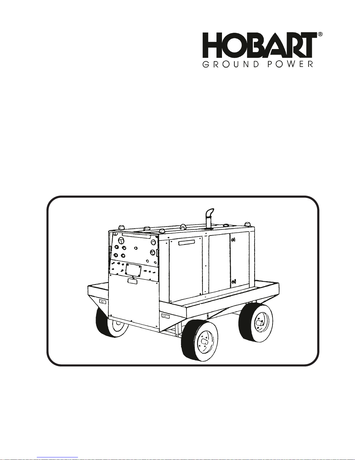
Jet-Ex 4D
Generator Sets
Series 7003A-3 and
Series 7003B-3
Hobart Brothers Company
Airport Systems Group
Ground Power Equipment
Troy, Ohio
U.S.A.
Page 2

This page intentionally left blank.
Page 3
OM-2063 / Operation and Maintenance Manual
Jet-Ex 4D / Spec. 7003A-3 / Generator Set
Section 1. Safety Instructions and Warnings
WARNING
ELECTRIC SHOCK can KILL. Do not touch live electrical parts.
ELECTRIC ARC FLASH can injure eyes, burn skin, cause equipment damage,
and ignite combustible material. DO NOT use power cables to breakload and
prevent tools from causing short circuits.
IMPROPER PHASE CONNECTION, PARALLELING, OR USE can damage
this and attached equipment
Important: Protect all operating personnel. Read, understand, and follow all instructions in
the Operating/Instruction Manual before installing, operating, or servicing the
equipment. Keep the manual available for future use by all operators.
1. General
Equipment that supplies electrical power can cause serious injury or death, or damage to other
equipment or property. The operator must strictly observe all safety rules and take precautionary
actions. Safe practices have been developed from past experience in the use of power source
equipment. While certain practices below apply only to electrically-powered equipment, other practices
apply to engine-driven equipment, and some practices to both.
2. Shock Prevention
Bare conductors, or terminals in the output circuit, or ungrounded, electrically-live equipment can fatally
shock a person. Have a certified electrician verify that the equipment is adequately grounded and learn
what terminals and parts are electrically HOT. Avoid hot spots on machine. Use proper safety clothing,
procedures, and test equipment.
The electrical resistance of the body is decreased when wet, permitting dangerous currents to flow
through it. When inspecting or servicing equipment, do not work in damp areas. Stand on a dry rubber
mat or dry wood, use insulating gloves when dampness or sweat cannot be avoided. Keep clothing dry,
and never work alone
a. Installation and Grounding of Electrically Powered Equipment
Equipment driven by electric motors (rather than by diesel or gasoline engines) must be installed
and maintained in accordance with the N ational Electrical Code, ANSI/NFPA 70, or other applicable
codes. A power disconnect switch or circuit breaker must be located at the equipment. Check the
nameplate for voltage, frequency, and phase requirements. If only 3-phase power is available,
connect any single-phase rated equipment to only two wires of the 3-phase line. DO NOT
CONNECT the equipment grounding conductor (lead) to the third live wire of the 3-phase line, as this
makes the equipment frame electrically HOT, which can cause a fatal shock.
Always connect the grounding lead, if supplied in a power line cable, to the grounded switch box or
building ground. If not provided, use a separate grounding lead. Ensure that the current
(amperage) capacity of the grounding lead will be adequate for the worst fault current situation.
Refer to the National Electrical Code ANSI/NFPA 70 for details. Do not remove plug ground prongs.
Use correctly mating receptacles.
Revised Safety Warnings
August 01/95 Page 1
Page 4

Om-2063 Operation and Maintenance Manual
Jet-Ex 4D / Spec. 7003A-3 / Generator Set
b. Output Cables and Terminals
Inspect cables frequently for damage to the insulation and the connectors. Replace or repair
cracked or worn cables immediately. Do not overload cables. Do not touch output terminal while
equipment is energized.
c. Service and Maintenance
(1)
This equipment must be maintained in good electrical and mechanical condition to avoid hazards
stemming from disrepair. Report any equipment defect or safety hazard to the supervisor and
discontinue use of the equipment until its safety has been assured. Repairs should be made by
qualified personnel only.
(2)
Before inspecting or servicing electrically-powered equipment, take the following precautions:
(3)
Shut OFF all power at the disconnecting switch or line breaker before inspecting or servicing the
equipment.
(4)
Lock switch OPEN (or remove line fuses) so that power cannot be turned on accidentally.
(5)
Disconnect power to equipment if it is out of service.
(6)
If troubleshooting must be done with the unit energized, have another person present who is
trained in turning off the equipment and providing or calling for first aid.
3. Fire and Explosion Prevention
Fire and explosion are caused by electrical short circuits, combustible material near engine exhaust
piping, misuse of batteries and fuel, or unsafe operating or fueling conditions.
a. Electrical Short Circuits and Overloads
Overloaded or shorted equipment can become hot enough to cause fires by self destruction or by
causing nearby combustibles to ignite. For electrically-powered equipment, provide primary input
protection to remove short circuited or heavily overloaded equipment from the line.
b. Batteries
Batteries may explode and/or give off flammable hydrogen gas. Acid and arcing from a ruptured
battery can cause fires and additional failures. When servicing, do not smoke, cause sparking, or
use open flame near the battery.
c. Engine Fuel
Use only approved fuel container or fueling system. Fires and explosions can occur if the fuel tank is
not grounded prior to or during fuel transfer. Shut unit DOWN before removing fuel tank cap. DO
NOT completely fill tank, because heat from the equipment may cause fuel expansion overflow.
Remove all spilled fuel IMMEDIATELY, including any that penetrates the unit. After clean-up, open
equipment doors and blow fumes away with compressed air.
4. Toxic Fume Prevention
Carbon monoxide - Engine exhaust fumes can kill and cause health problems. Pipe or vent the exhaust
fumes to a suitable exhaust duct or outdoors. Never locate engine exhausts near intake ducts of air
conditioners.
5. Bodily Injury Prevention
Serious injury can result from contact with fans inside some equipment. Shut DOWN such equipment
for inspection and routine maintenance. When equipment is in operation, use extreme care in doing
necessary trouble-shooting and adjustment. Do not remove guards while equipment is operating.
6. Medical and First Aid Treatment
First aid facilities and a qualified first aid person should be available for each shift for immediate
treatment of all injury victims. Electric shock victims should be checked by a physician and taken to a
hospital immediately if any abnormal signs are observed.
Safety Warnings Revised
Page 2 August 01/95
Page 5

OM-2063 / Operation and Maintenance Manual
Jet-Ex 4D / Spec. 7003A-3 / Generator Set
EMERGENCY
FIRST AID
Call physician immediately. Seek additional assistance. Use First Aid
techniques recommended by American Red Cross until medical help arrives.
IF BREATHING IS DIFFICULT, give oxygen, if available, and have victim lie
down. FOR ELECTRICAL SHOCK, turn off power. Remove victim; if not
breathing, begin artificial respiration, preferably mouth-to-mouth. If no detectable
pulse, begin external heart massage. CALL EMERGENCY RESCUE SQUAD
IMMEDIATELY
7. Equipment Precautionary Labels
Inspect all precautionary labels on the equipment monthly. Order and inspect all labels that cannot be
easily read.
Revised Safety Warnings
August 01/95 Page 3
Page 6

Om-2063 Operation and Maintenance Manual
Jet-Ex 4D / Spec. 7003A-3 / Generator Set
This page intentionally left blank
Safety Warnings Revised
Page 4 August 01/95
Page 7

OM-2063 / Operation and Maintenance Manual
Jet-Ex 4D / Spec. 7003A-3 and 7003B-3 / Generator Sets
Introduction
This manual contains operation and service information for 28.5 V DC Generator sets identified as
Jet-Ex 4D . These units are available as stationary, skid- mounted units, or they may be trailer-mounted for
portability. Both versions are available with 14 V DC output capability.
The primary purpose of the manual is t o provide information and instructions to experienced operators,
electricians, and mechanics who are not familiar with this equipment. The intent of the manual is to guide
and assist operators and maintenance personnel in the proper use and care of the equipment.
Read the instructions before starting the unit. Learn to use the manual and to locate information contained in
it.
The Table of Contents, which follows this Introduction, lists all Chapters, Sections, and the paragraph titles
within each Section. The location of each listing is identified by Chapter, Section and page number.
Each Chapter is divided into as many Sections as necessary. Sections are always referred to by a
combination Chapter-Section number, for example: 2-3 refers to Chapter 2, Section 3.
The material within each Section is divided into main subjects with applicable paragraph headings and
sub-headings as required. For example, a portion of the Description Section might logically follow this
arrangement and paragraphing:
Section 1. Description
1. Engine, Generator and Controls
a. Interior Panel
(1)
Protective devices
a. Overload relay
(2)
Contactors
Page numbers do not run consecutively throughout the manual. Each page is identified by the ChapterSection number in which it appears, and by a page number within the Chapter-Section. Therefore, the first
page in each Section is page 1. These identifying numbers appear in the lower, outside corner of each page.
Each page also bears a date located in the corner opposite the page number. This date is either that of
original issue, or of the latest revision. Any revision to the original text is identified by a heavy black line in the
left-hand margin. Illustrations follow a numbering system similar to page numbering. The first Figure in each
SectionisFigure1.
All tables, charts and diagrams, as well as illustrations, are identified by Figure numbers to avoid confusion.
The general location of any particular information can be found quickly by running through the Table of
Contents. For example: to locate any adjustment information, a quick look at the Table of Contents shows that
“Adjustment / Test” is located in Chapter 2, Section 3,
Portions of the text are referred to by identifying the paragraph in which the referenced material may be found.
When referenced material is located in the same Chapter/Section as the reference, only the paragraph
identification is given, for example:
of the same Section.
(Ref. Para. 1, A)
(shown as 2-3)
means that the material is to be found in paragraph 1, A,
.
Dec 31/92 Introduction
Page i
Page 8

OM-2063 / Operation and Manitenance Manual
Jet-Ex 4D / Spec. 7003A-3 and 7003B-3 / Generator Sets
When referenced material is located in another Chapter/Section, both the Chapter and Section numbers and
the paragraph identification are given, for example:
(Ref. 1-2, Para. 1, A)
means that the referenced material
is located in Chapter-Section 1-2, and paragraph 1,a. within that Chapter-Section.
Components shown in illustrations, and the illustrations themselves, are referenced in a similar manner.
When this type of reference is made, the item number of the part and the Figure number in which it appears
are given, for example:
(2, Fig.3)
refer to item number 2 in illustration Figure 3 of the same Chapter/Section.
When a referenced figure appears in another Chapter/Section, the reference will include the Chapter/Section
number, for example:
(2-3, 1, Fig. 4)
tells the user that the information is in Chapter/Section 2-3, and to refer
toitem1inFigure4.
Once a Figure number reference has been established, the Figure number is not repeated and only the item
numbers of the parts involved are referenced, for example: “Loosen screw
(6)
and remove brush
.
(2, Fig.6)
slide out connector
(4)
,
When an item number is referenced without a Figure number, it always applies to the last preceding Figure
number mentioned in the text.
A collection of manufacturer’s literature is supplied as part of the information package.
If you have any questions concerning your Hobart Power Systems Group equipment, you are invited to
contact our Service Department by mail, telephone, or FAX.
Write: Hobart Brothers Company
Airport Systems Group
Ground Power Division
Service Department
Troy, Ohio 45373
U.S.A.
Call: (937) 332-5060 (Service Assistance)
(937) 332-5050 (Replacement Parts)
FAX: (937) 332-5121
Introduction Dec 31/92
Page ii
Page 9

OM-2063 / Operation and Maintenance Manual
Jet-Ex 4D / Spec. 7003A-3 and 7003B / Generator Sets
Table of Contents
Chapter 1. Description/Operation
Section 1. Safety Instructions and Warnings 1-1 1
Section 2. Description 1-2 1
General 1-2 1
Special Features 1-2 1
Orientation 1-2 1
Identification 1-2 1
Canopy 1-2 4
Engine, Generator, and Controls 1-2 4
General.................................................... 1-2 4
Engine..................................................... 1-2 4
Generator 1-2 6
Control Panel Assembly 1-2 6
General.................................................... 1-2 6
Lights...................................................... 1-2 6
Monitoringinstruments....................................... 1-2 6
Potentiometer............................................... 1-2 6
Switches................................................... 1-2 6
Fuses...................................................... 1-2 8
Voltageregulator............................................ 1-2 8
Overvoltage module. . . . . . . . . . . . . . . . . . . . . . . . . . . . . . . . . . . . . . . . . . 1-2 9
Resistoranddiodeassembly.................................. 1-2 9
Excitationrectifiers.......................................... 1-2 9
Voltagesensingrelay ........................................ 1-2 9
Contactor 1-2 9
Output Terminals 1-2 9
Rectifier Assembly 1-2 9
Ammeter Shunt 1-2 9
Section 3. Preparation for Use, Storage or Shipping 1-3 1
Preparation for Use 1-3 1
General.................................................... 1-3 1
Inspection/Check............................................ 1-3 1
Dec 31/92 Table of Contents
Page iii
Page 10

OM-2063 / Operation and Maintenance Manual
Jet-Ex 4D / Spec. 7003A-3 and 7003B / Generator Sets
Preparation for Storage 1-3 3
General....................................................1-3 3
TemporaryStorage...........................................1-3 3
LongTimeStorage...........................................1-3 3
Preparation for Shipping 1-3 4
Section 4. Operation 1-4 1
General 1-4 1
Operating the Generator Set 1-4 1
Pre-startInspection..........................................1-4 1
Pre-startInstructions.........................................1-4 1
StartingTheEngine ..........................................1-4 2
GeneratorOperation..........................................1-4 3
AdverseWeatherPrecautions.................................. 1-4 3
OperationinHotandHumidConditions.......................... 1-4 4
OperationinExtremelyDustyConditions........................ 1-4 5
OperationinSaltWaterAreas.................................. 1-4 5
Miscellaneous...............................................1-4 5
Chapter 2. Servicing/Troubleshooting
Section 1. Maintenance Inspection/Check 2-1 1
General 2-1 1
Maintenance Schedule 2-1 1
General..................................................... 2-1 1
MaintenanceScheduleCheckSheet.............................2-1 1
TimeIntervals...............................................2-1 1
Engine and Related Components 2-1 1
Inspection and Cleaning 2-1 1
Section 2. Troubleshooting Procedures 2-2 1
General 2-2 1
Troubleshooting Chart 2-2 1
Description ................................................. 2-2 1
Use of the Troubleshooting Chart. . . . . . . . . . . . . . . . . . . . . . . . . . . . . . . 2-2 1
Equipment for Troubleshooting 2-2 1
Diagrams 2-2 1
Illustrations 2-2 1
Connections and Wiring 2-2 1
Engine and Controls 2-2 5
Generator and Controls 2-2 9
Section 3. Maintenance Procedures 2-3 1
General 2-3 1
Table of Contents Dec 31/92
Page iv
Page 11

OM-2063 / Operation and Maintenance Manual
Jet-Ex 4D / Spec. 7003A-3 and 7003B / Generator Sets
Lubrication 2-3 1
General.................................................... 2-3 1
LubricationChart............................................ 2-3 1
Generator .................................................. 2-3 1
GeneratorControls .......................................... 2-3 1
Engine..................................................... 2-3 1
Servicing the Air Cleaner 2-3 4
CartridgeRemoval........................................... 2-3 4
CartridgeInstallation......................................... 2-3 5
Servicing the Fuel Filter 2-3 5
DrainingtheFuel/WaterSeparatorBowl......................... 2-3 5
ReplacingtheFilterElement................................... 2-3 5
Drive Belt Service 2-3 6
Engine Cooling System 2-3 6
RustInhibitor............................................... 2-3 6
Antifreeze.................................................. 2-3 6
Battery Service 2-3 6
General.................................................... 2-3 6
BatteryLocationandAccessibility.............................. 2-3 6
BatteryCare................................................ 2-3 6
LiquidLevel ................................................ 2-3 7
CleaningtheBattery ......................................... 2-3 7
TestingaBattery............................................ 2-3 7
Generator Maintenance 2-3 8
General.................................................... 2-3 8
BrushService............................................... 2-3 8
GeneratorRevolvingFieldBrushReplacement................... 2-3 8
Section 4. Adjustment/Test 2-4 1
General 2-4 1
Testing the Generator Set 2-4 1
Pre-operationalTestProcedures............................... 2-4 1
OperationalTests............................................ 2-4 3
Voltage Regulator Adjustment 2-4 4
28.5VoltAdjustment......................................... 2-4 4
LineDropCompensation...................................... 2-4 4
Chapter 3. Overhaul/Major Repair
Dec 31/92 Table of Contents
Page v
Page 12

OM-2063 / Operation and Maintenance Manual
Jet-Ex 4D / Spec. 7003A-3 and 7003B / Generator Sets
Chapter 4. Illustrated Parts List
Table of Contents 4-1 1
Section 1. Introduction 4-1 3
General 4-1 3
Purpose 4-1 3
Arrangement 4-1 3
Explanation of Parts List 4-1 3
Contents ...................................................4-1 3
PartsListForm..............................................4-1 3
Section 2. Vendor Codes 4-2 1
Explanation of Vendor Code List 4-2 1
Section 3. Parts List 4-3 1
Explanation of Parts List Arrangement 4-3 1
Symbols and Abbreviations 4-3 1
Section 4. Numerical Index 4-4 1
Explanation of Numerical Index 4-4 1
Chapter 5. Manufacturer’s Literature
Unusual Service Conditions
Table of Contents Dec 31/92
Page vi
Page 13

OM-2063 / Operation and Maintenance Manual
Jet-Ex 4D / Spec. 7003A-3 and 7003B / Generator Sets
List of Illustrations
Chapter 1. Description/Operation
Section 1. Safety Instructions and Warnings
Section 2. Description
Jet-Ex4DPGeneratorSet..................................... 1-2 2
Generator Set Components. . . . . . . . . . . . . . . . . . . . . . . . . . . . . . . . . . . . 1-2 5
ControlPanelAssembly...................................... 1-2 7
VoltageRegulatorSupport.................................... 1-2 8
Section 3. Preparation for Use, Storage or Shipping
28VoltOutputTerminalPanel:Specification7003A-3.............. 1-3 2
Output Cable Connections: Specification 7003A-3 . . . . . . . . . . . . . . . . 1-3 3
Section 4. Operation
ControlPanelAssembly...................................... 1-4 2
Chapter 2. Servicing/Troubleshooting
Section 1. Maintenance Inspection/Check
Inspection/Check/MaintenanceSchedule........................ 2-1 2
Section 2. Troubleshooting Procedures
Generator Set Components. . . . . . . . . . . . . . . . . . . . . . . . . . . . . . . . . . . . 2-2 2
ControlPanelAssembly...................................... 2-2 3
VoltageRegulatorSupport.................................... 2-2 4
ElectricalConnectionDiagram-281329......................... 2-2 5
Electrical Schematic - 180436. . . . . . . . . . . . . . . . . . . . . . . . . . . . . . . . . . 2-2 9
Section 3. Maintenance Procedures
LubricationChart............................................ 2-3 2
Lubricants.................................................. 2-3 3
TemperatureandOilViscosityChart............................ 2-3 3
SymbolsandTimeIntervals................................... 2-3 3
Air Cleaner Cartridge Replacement . . . . . . . . . . . . . . . . . . . . . . . . . . . . . 2-3 4
Fuel/WaterSeparator......................................... 2-3 5
Dec 31/92 Table of Contents
Page vii
Page 14

OM-2063 / Operation and Maintenance Manual
Jet-Ex 4D / Spec. 7003A-3 and 7003B / Generator Sets
GeneratorRevolvingFieldBrushes............................. 2-3 8
Section 4. Adjustment/Test
OperatingControlsandIndicators..............................2-4 2
IdleSpeedAdjustment....................................... 2-4 3
VoltageRegulatorAdjustment ................................ 2-4 4
Chapter 3. Overhaul/Major Repair
Chapter 4. Illustrated Parts List
Section 1. Introduction
Section 2. Vendor Codes
Section 3. Parts List
Generator Set w/Portable Mounting. . . . . . . . . . . . . . . . . . . . . . . . . . . . . 4-3 2
Trailerw/FendersandCableTrays.............................. 4-3 4
Trailer Assembly . . . . . . . . . . . . . . . . . . . . . . . . . . . . . . . . . . . . . . . . . . . . . 4-3 6
Canopy Assembly. . . . . . . . . . . . . . . . . . . . . . . . . . . . . . . . . . . . . . . . . . . . 4-3 10
GeneratorSetwithoutcanopy.................................. 4-3 12
ControlPanel................................................ 4-3 16
P.C. Board Box Assembly . . . . . . . . . . . . . . . . . . . . . . . . . . . . . . . . . . . . . 4-3 18
Fuel Tank Support Assembly . . . . . . . . . . . . . . . . . . . . . . . . . . . . . . . . . . 4-3 20
FullThrottleSolenoid......................................... 4-3 22
BatteryInstallation........................................... 4-3 24
FuelSystem................................................. 4-3 26
Filter,Fuel/WaterSeparator.................................... 4-3 28
CoolingSystem.............................................. 4-3 30
WaterHeaterInstallationKit ................................... 4-3 32
RectifierAssembly........................................... 4-3 34
RectifierAssembly........................................... 4-3 36
Brushholder Assembly. . . . . . . . . . . . . . . . . . . . . . . . . . . . . . . . . . . . . . . . 4-3 40
Lifting Yoke & Frame Assembly . . . . . . . . . . . . . . . . . . . . . . . . . . . . . . . . 4-3 42
GeneratorAssembly.......................................... 4-3 44
Section 4. Numerical Index
Chapter 5. Manufacturer’s Literature
Unusual Service Conditions
Table of Contents Dec 31/92
Page viii
Page 15

OM-2063 / Operation and Maintenance Manual
Jet-Ex 4D / Specs 7003A-3 and 7003B-3 / Generator Sets
Section 2. Description
1. General
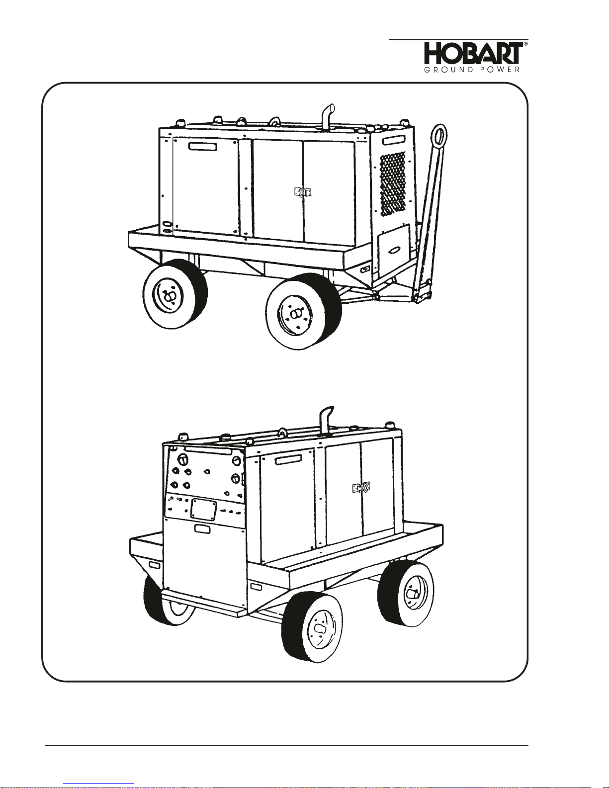
The two Jet-Ex 4D units covered in this manual
trailer-mounted generator sets manufactured by Hobart Brothers Company, Ground Power Division,
Troy, Ohio U.S.A. They are identified by specification numbers 7003A-3 and 7003B-3.
The basic generator set is designed to generate and deliver 28.5 volts DC power to an aircraft when its
on-board generators are shut down. In addition to providing continuous, regulated power to the aircraft,
the unit is designed for starting any fixed-wing aircraft or helicopter which is equipped with an external
28.5 volt DC power receptacle (see page 3 for complete Specifications and Capabilities).
The Specification 7003B-3 generator set is virtually identical to the Specification 7003A-3 generator set,
except that it has a Furnas contactor and a different air cleaner.
2. Special Features
The “Soft-Start” current limiting feature, recommended by most aircraft engine manufacturers, provide
the operator with controls to limit the inrush current to the aircraft engine’s starter. When the operator
presets this control, the generator will provide constant voltage to the preset current value. As more
current is applied beyond the preset current value, the voltage will decrease to a minimum of 14 volts
DC, after which the voltage will remain constant as more current may be delivered beyond the preset
current value. Limiting inrush current is recommended by most engine manufacturers to protect the
aircraft engine’s starter shear section. The current limiting control is continuously adjustable from 300
amperes, which is recommended for helicopter and small turbine starting, to 2000 amperes, required for
starting larger aircraft engines when the control is turned fully clockwise.
A four-wheel trailer is available to add mobility to the generator set. It is equipped with pneumatic rubber
tires, a drawbar for towing, and hand lever-operated, parking brake. It also includes fenders, bumpers
and cable trays. This option is available from Hobart Brothers as Part No.181000-1.
A water heater kit is installed inside the enclosure and is connected to the cooling system of the diesel
engine. Its purpose is to keep the coolant warm when the engine is shut down for extended periods of
time in cold weather and permit the engine to start quickly.
A fuel/water separator, attached to the side of the engine, replaces the standard prefilter. This special
filter removes water/condensation along with any solid contaminants from the fuel.
(Figure 1)
are diesel engine driven, self-contained,
3. Orientation
The radiator end of the Jet-Ex 4D is the front. Right and left are determined by standing at the rear of
the unit, facing it. The control panel is located at the rear.
4. Identification
Each generator set has an Identification plate attached inside the hinged control panel door. This
nameplate lists the machines Model No. (Jet-Ex 4D), Specification No., Serial No., and electrical rating.
If any of the options described in paragraph 2.b. are included, they will be listed by name and part
number on a separate option nameplate located next to the Identification plate.
Dec 31/92 Chapter 1-2
Page 1
Page 16
OM-2063 / Operation and Maintenance Manual
Jet-Ex 4D / Specs 7003A-3 and 7003B-3 / Generator Sets
Chapter 1-2 Dec 31/92
Page 2
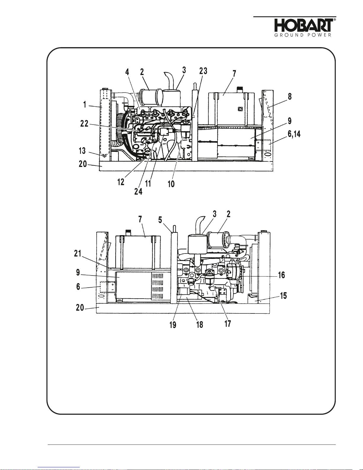
Jet-Ex 4DP Generator Set
Figure 1
Page 17
OM-2063 / Operation and Maintenance Manual
Jet-Ex 4D / Specs 7003A-3 and 7003B-3 / Generator Sets
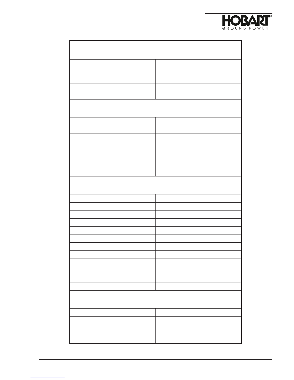
Unit with Trailer, Fenders & Cable Tray
Length 75.5 inches (1918 mm)
Width 58 inches (1473 mm)
Height 63.75 inches (1632 mm)
Weight (dry fuel tank) 2410 pounds (1093 kg)
Ground Clearance 7.5 inches (191 mm)
Generator
Output Power Rating 15.7 kW
Voltage 28.5 volts DC
Rated Load Capacity 550amperes continuous at 28.5
volts DC
Starting Current Capacity 200 amperes maximum
Current Limiting Capability 300 to 2000 amperes, continuously
adjustable
Operating Speed 2000 RPM
Engine
Manufacturer Perkins Diesel
Model 4.236
Type 4-cylinder, 4-stroke, direct injection
Fuel ASTM D975 66T Numbers 1D or 2D
Displacement 236 cubic inches (3.68 liters)
Rated Power at 2000 RPM 70 Horsepower
Oil Capacity (without filter change) 8 quarts (7.57 liters)
Coolant Capacity 3.5 U.S. gallons
Electrical System 12 volt DC, negative ground
Governed Speed at No Load 2000 +/- 50 RPM
Idle Speed 1000 +/- 50 RPM
Fuel Tank Capacity 21.5 U.S. gallons (81.4 liters)
Protective Devices
Generator Engine
28.5 volt overvoltage module trips at
32 to 34 volts.
14 volt overvoltage module trips at
18 to 20 volts.
Water Temperature Switch opens
engine circuit at 225 F.
Low Oil Pressure Swiych opens at
20 PSI (138 kPa).
Dec 31/92 Chapter 1-2
Page 3
Page 18

OM-2063 / Operation and Maintenance Manual
Jet-Ex 4D / Specs 7003A-3 and 7003B-3 / Generator Sets
5. Canopy
The standard canopy is a sheet metal enclosure which protects the engine, generator, and electrical
controls. It has two hinged doors on each side at the front to provide access for service and
maintenance. Panels at the rear provide access to the generator. The left rear panel has a round hole
in it to permit viewing the fuel gage mounted in the fuel tank.
6. Engine, Generator, and Controls
a. General
(4)
Refer to Figure 2. The engine
(21)
fuel tank support
mounting frame for the load contactor (14) and output terminals. The radiator
front canopy. A heavy U-bolt is attached to the centrally located lifting yoke
generator set with a crane or hoist.
b. Engine
(1)
General
The engine used in the Jet-Ex 4D generator set is a Perkins four-cylinder, four-stroke, direct
injection diesel engine. It has a 236 cubic inch
compression ratio. Engine firing order is 1-3-4-2.
A spring-loaded relief valve in the pump limits maximum pressure in the system. A full-flow oil
filter
(12, Figure 2)
system. A valve in the filter provides a bypass to an oil gallery in case the filter becomes
clogged. A low oil pressure switch is mounted on the engine block as a protective device. The
primary ignition circuit is wired through the contacts of this switch, which closes at 20 PSI
. This prevents the engine from running if oil pressure will not build up, and also shuts down
kPa)
the engine if oil pressure drops radically during operation. (See Figure 2 and the engine
operator’s manual for engine specifications).
The generator and engine are mounted on a welded steel skid, and are enclosed by a sheet
metal canopy that bolts to the skid. Access to engine serviceable components
located at the rear of the unit supports the fuel tank
cleans the entire output of the pump before it enters the oil distributing
cleaner, and rectifier assembly, etc.)
machine.
Two removable panels to the right side and one to the left rear allow access to the other
components such as the load contactor and output terminals. The rear panel is removable and
permits access to the rectifier assembly.
and generator
is through two doors at the front on each side of the
(9)
are mounted on a welded steel frame
(7)
and provides a
(1)
is mounted to the
(5)
for moving the
(3.86 liter)
cylinder displacement and a 16:1
(oil filter, air
(20)
.A
(138
(2)
Cooling fan
The cooling fan on the engine is designed to blow air out through the radiator rather than to draw
it in. This prevents hot air, heated by the engine, from entering the generator.
(3)
Fuel system
The fuel system consists of an 2l.5-gallon
fittings and hoses.
(4)
Alternator and regulator
The battery charging alternator
sets. The voltage regulator is an integral part of each of the alternator.
(5)
Starter relay
The starter relay
engine.
(6)
Exhaust muffler
This muffler helps deaden audible noise from the engine’s exhaust.
Chapter 1-2 Dec 31/92
Page 4
(19, Figure 2)
(3, Figure 2)
(81.4 liters)
(16, Figure 2)
is mounted on the starter motor
is rated at 62 amperes on Series 7003 generator
tank
(7, Figure 2)
with all the necessary
(18)
, on the right side of the
Page 19
OM-2063 / Operation and Maintenance Manual
Jet-Ex 4D / Specs 7003A-3 and 7003B-3 / Generator Sets
1. Radiator
2. Air cleaner
3. Muffler
4. Engine
5. Lifting yoke
6. Rectifier assembly
7. Fuel tank
8. Control panel
9. Generator
Dec 31/92 Chapter 1-2
10. Fuel filter
11. Throttle control solenoid
12. Oil filter
13. Drain cock & switch
14. Load contactor
15. Batteries
16. Alternator
17. Fuel filter
18. Starter
Generator Set Components
Figure 2
19. Starter relay
20. Frame
21. Fuel tank support
22. Engine governor
23. Water temperature
sender
24. Oil pressure sender
Page 5
Page 20

OM-2063 / Operation and Maintenance Manual
Jet-Ex 4D / Specs 7003A-3 and 7003B-3 / Generator Sets
7. Generator
The generator
whose output is rectified. The output is rectified by a rectifier assembly
connected into a full wave configuration. The generator is self-excited and receives excitation from a
three phase full wave rectified stator winding. One positive and one negative brush in contact with slip
rings supply controlled excitation current from the stator winding through the voltage regulator to the
rotating field winding. The voltage regulator controls the excitation current and maintains a constant
output voltage. Access to the brushes is through holes in the anti-drive end bracket. The rotor is
supported at the anti-drive end
the engine fly-wheel by a flexible disc and hub coupling assembly and is supported by the engine main
bearings. A radial-blade fan of formed and welded sheet metal construction is mounted on the coupling
hub and draws cooling air over the generator windings.
Air enters through the anti-drive end of the generator and is discharged through openings in the flywheel
housing at the drive end, to cool the rectifier assembly above it. The g enerator housing assembly, which
contains the generator stator, is bolted to the engine flywheel housing.
(9, Figure 2)
is a multi-phase, synchronous salient pole, revolving field, AC generator
(6)
made up of twelve rectifiers
(slip ring end)
by a single-row ball bearing. The drive end is connected to
8. Control Panel Assembly
a. General
The hinged control panel
monitoring instruments, voltage regulator, relays, etc. The panel is mounted at the rear of the
canopy. The controls are accessible behind a hinged Lexan cover.
(8, Figure 2)
houses and provides mounting facilities for controls,
b. Lights
Two panel lights
(12) glows when the output load contactor is closed, and another one
engine is running.
c. Monitoring instruments
The voltmeter
generator current.
A tachometer
from the alternator.
A water temperature gauge
temperature sender
An oil pressure gauge
operated by a sender
The ammeter
electrical system.
The hourmeter
d. Potentiometer
The current limiting potentiometer
aircraft. The current limiting setting is continuously adjustable from 300 to 2000 amperes.
e. Switches
The contactor control switch
the output load contactor. The top CLOSE position is spring-loaded and is held momentarily until the
contactor closed light
position. In this position the switch provides holding current to the load contactor to keep it closed.
Protective devices in the load contactor circuit provide protection against overvoltage by opening the
load contactor if that condition occurs. In the bottom OFF position, the contactor is opened. The
push-to-build-up-voltage switch
generator fields with 12 volt engine circuit when flashing the fields.
(7, Figure 3)
(6, Figure 3)
(2)
displays the engine speed in RPM. This instrument receives its operating signal
(23, Figure 2)
(1, Figure 3)
(24, Figure 2)
(19, Figure 3)
(15)
records the total hours of engine operation for scheduling maintenance.
(12)
provide illumination for instruments and controls. One green pilot light
(14)
glows green when the
indicates generator output voltage, and the ammeter
(3)
indicates the engine coolant temperature and is actuated by a
mounted on the engine’s water jacket.
displays the pressure in the engine’s lubrication system. It is
mounted on the engine block.
indicates the rate of charge or discharge in the engine’s 12 volt DC
(4)
is used to select the starting current recommended for various
(11, Figure 3)
glows, then it is released to the center ON
(10)
is a three-position toggle switch used to close and open
is a momentary contact pushbutton switch which flashes the
(5)
displays
Chapter 1-2 Dec 31/92
Page 6
Page 21
OM-2063 / Operation and Maintenance Manual
Jet-Ex 4D / Specs 7003A-3 and 7003B-3 / Generator Sets
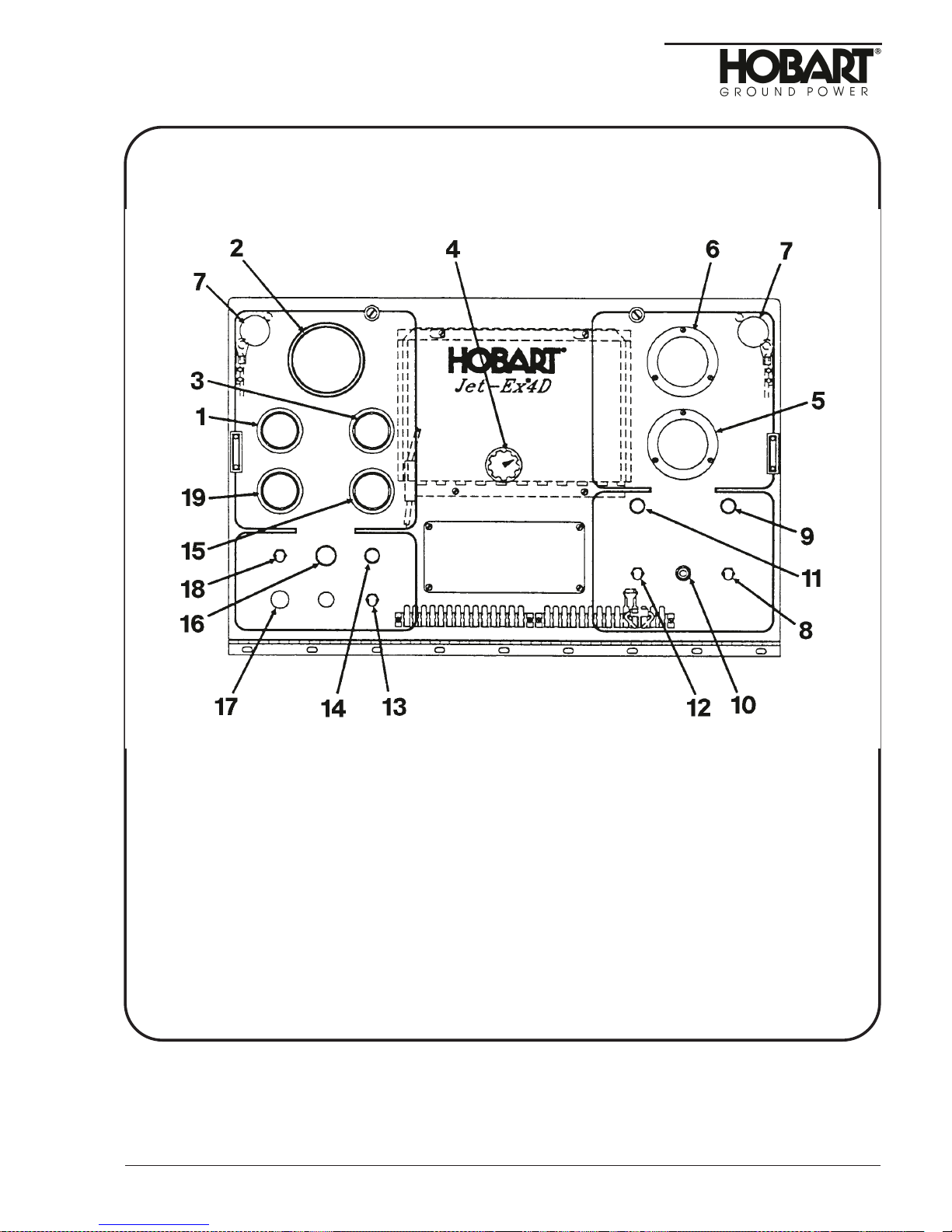
1. Oil Pressure Guage
2. Tachometer
3. Water Temperature Guage
4. Current Limit Control
5. Ammeter
(Generator)
6. Voltmeter
7. Panel Light
8. Panel Lights Switch
9. Panel Lights Fuse
10. Push-To-Build-Up-Voltage Switch
Dec 31/92 Chapter 1-2
Control Panel Assembly
Figure 3
11. Contactor Closed Switch
12. Contactor Closed Light
13. Speed Control Switch
14. Engine On Light
15. Hourmeter
16. Engine Control Switch
17. Engine Circuit Fuse
18. Engine Circuit
19. Ammeter
(Engine)
Page 7
Page 22
OM-2063 / Operation and Maintenance Manual
Jet-Ex 4D / Specs 7003A-3 and 7003B-3 / Generator Sets
The panel lights switch
momentary contact pushbutton which closes the starter relay
This switch is operable only when the engine switch
position.
The engine switch
to center RUN position. The engine ON light
In the bottom STOP position, the switch will stop the engine and the light
Refer to Figure 3. The speed control switch,
device on the engine. In the IDLE position, used for starting, the engine speed is controlled
approximately. In the Rated RPM position, engine speed is controlled to approximately
2000 RPM.
f. Fuses
Three cartridge-type fuses protect the engine ignition circuit, the panel lights circuit, and the voltage
regulator. The engine circuit fuse
amperes, and the voltage regulator fuse
g. Voltage regulator
Refer to Figure 4. The voltage regulator
generator output after the voltage is built up.
(8, Figure 3)
(18)
, when released from its top START position after the engine starts, will return
turns the lights
(14)
(13)
(13, Figure 3)
(4, Fig. 4)
(1)
is a solid-state device which regulates the 28.5 volt DC
(7)
on and off. The engine start switch
(8, Figure 2)
(18)
is held in its top spring-loaded START
will glow as long as the switch is in RUN position.
is a two-position toggle switch wired to an idling
is rated at 20 amperes, the panel lights fuse
at 10 amperes.
and cranks the engine.
(14)
will go out.
(16)
(9)
is a
at 10
Chapter 1-2 Dec 31/92
Page 8
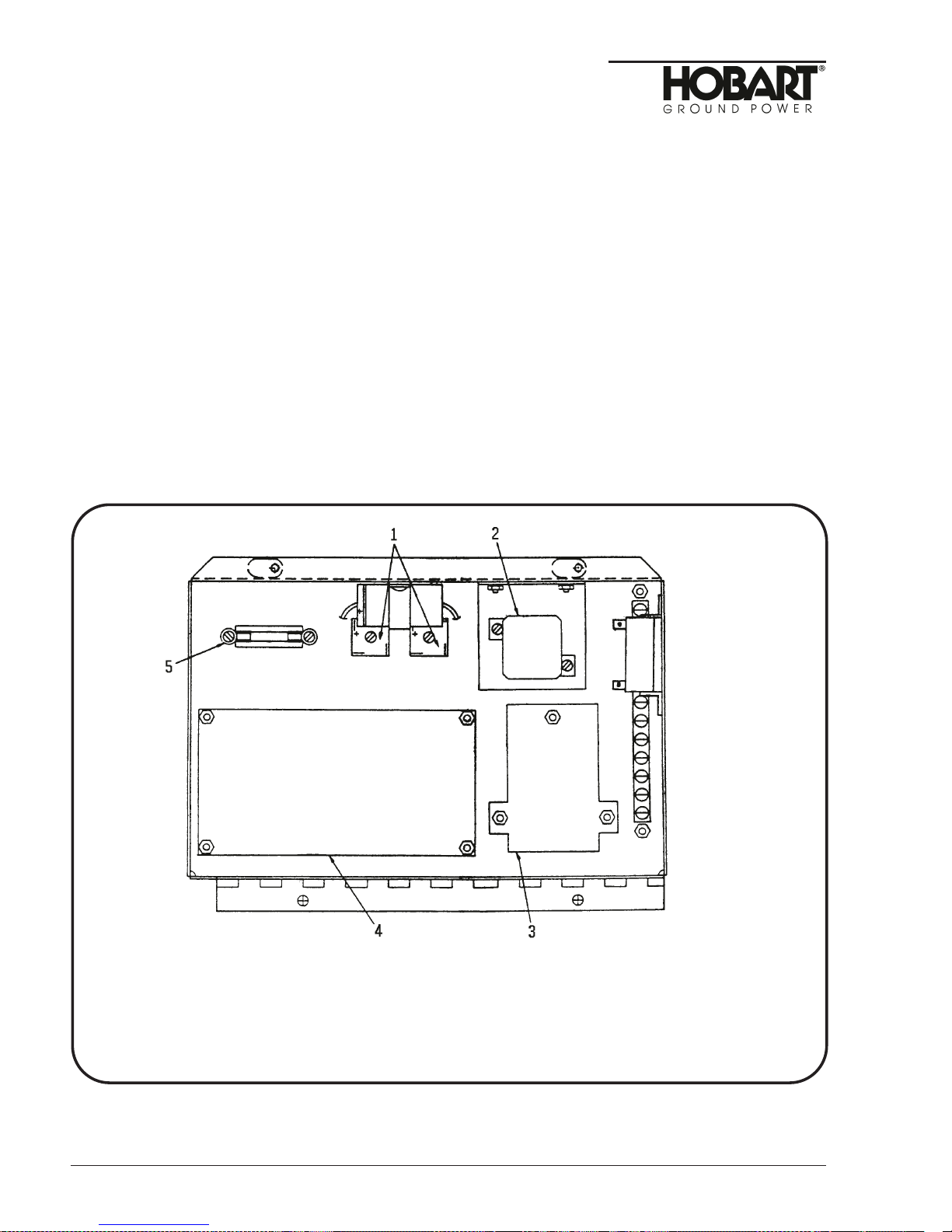
1. Excitation Rectifiers
2. Voltage Sensing Relay
3. Overvoltage Relay
4. Voltage Regulator
5. Voltage Regulator Fuse
Voltage Regulator Support
Figure 4
Page 23

OM-2063 / Operation and Maintenance Manual
Jet-Ex 4D / Specs 7003A-3 and 7003B-3 / Generator Sets
h. Overvoltage module
(2)
The overvoltage relay
closed relay in the circuit is wired into the load contactor coil circuit. An overvoltage condition causes
the relay contacts to open, which in turn prevents the contactor from closing, or opens the load
contactor and discontinues the power delivery. The overvoltage module is adjusted to trip at 32 to 34
voltsDCin2to10seconds.
i. Resistor and diode assembly
This network, which is mounted on a terminal strip behind the control panel, protects the load
contactor hold circuit against excessive current draw when the generator is delivering power.
j. Excitation rectifiers
Two diode bridge rectifiers, CR418 and CR418,
armature to the DC voltage needed for the generator revolving field.
k. Voltage sensing relay
Voltage sensing relay K406
circuit of the revolving field to prevent excessive voltage build-up if the push-to-build-up-voltage
switch is held in too long, or if it is pushed in after voltage is built up.
is a solid-state protective device on a printed circuit board. A normally
(5, Fig. 4)
(3, Fig. 4)
is a safety device which automatically opens the grounding
convert an AC voltage from the generator
9. Contactor
The load contactor, which is mounted behind the control panel on the fuel tank support, provides a safe
and convenient means of connecting and disconnecting the generator from the load. Initial power for
closing the load contactor is supplied by the generator through the spring-loaded momentary contacts of
the contactor control switch
the normally open auxiliary contacts in the load contactor.
(11, Figure 3)
. Holding power, to keep the contactor closed, passes through
10. Output Terminals
The output terminal panel is mounted inside the unit just behind the control panel. The positive terminal
is the A2 terminal of the load contactor, and the negative terminal is to the right of the load contactor.
11. Rectifier Assembly
This assembly consists of two aluminum heat sinks with twelve diodes on each heat sink. The rectifier
assembly converts the AC output of the generator to 28.5 VDC.
12. Ammeter Shunt
The ammeter shunt is connected in the generator’s negative output circuit. It supplies a small voltage
proportional to output current for operation of the generator ammeter
current for the current limit circuit of the voltage regulator
negative heat sink of the rectifier assembly
(6,Fig.2)
(1, Fig. 4)
.
(5, Fig. 3)
. This shunt is mounted on the
and for sensing output
Dec 31/92 Chapter 1-2
Page 9
Page 24

OM-2063 / Operation and Maintenance Manual
Jet-Ex 4D / Specs 7003A-3 and 7003B-3 / Generator Sets
This page intentionally left blank
Chapter 1-2 Dec 31/92
Page 10
Page 25
OM-2063 / Operation and Maintenance Manual
Jet-Ex 4D / Spec. 7003A-3 and 7003B-3 / Generator Sets
Section 3. Preparation for Use, Storage or Shipping
1. Preparation for Use
a. General
The generator set is shipped with an empty fuel tank. After the fuel tank filled and the generator set
inspected, the generator set is ready for use.
CAUTION
Read operating instructions in Section 1-4 before operating the unit.
b. Inspection/Check
Inspect the unit completely prior to operation.
(1)
Remove crating, blocking, banding, ties, and other securing and protective material. After
shipping carton is removed, remove the four carton supports from the bases of the clearance
lights. Then install the attached clearance light lenses in their bases.
(2)
Inspect exterior for shipping damage such as broken glass, damaged sheet metal, etc.
(3)
Open canopy door and inspect interior for foreign material such as rags, tools or shipping papers.
(4)
Check fuel, coolant, and oil hoses and connections for visible leaks. If leaks are discovered,
correct by tightening hose clamps, tube fittings, etc., as required.
(5)
Check security of attaching and retaining hardware.
(6)
Check the following for sufficient quantity.
a. Fuel
Fuel tank capacity is 21.5 gallons (81.4 liters).
b. Engine coolant
The radiator cap is located above the front canopy, Coolant level should be approximately
one inch below the filler neck. Allow a sufficient capacity for coolant expansion.
CAUTION
c. Engine lubricating oil
The oil level dipstick is located on the right side of the engine. Refer to Perkins User’s
andbook for oil recommendations.
(7)
Output Cable Installation
Units are normally supplied without a generator-to-aircraft cable.
a. Cable requirements
• Cable length is determined by the customer’s requirements. It is recommended that the
• The recommended single conductor sizes for 28.5 volt DC, continuous rated amperage
Be sure the cooling system antifreeze solution is adequate to protect below
lowest temperature expected.
cable be no longer than 30 feet (9 m). The cable should be two conductor with lug-type
terminals on one end and an AN-2551 plug connector on the other.
o
C
and 90
4/0 size for 530 amperes use 350 MCM size
(194oF)
rise is as follows: for 285 amperes use 2/0 size for 385 amperes use
Dec 31/92 Chapter 1-3
Page 1
Page 26
OM-2063 / Operation and Maintenance Manual
Jet-Ex 4D / Specs 7003A-3 and 7003B-3 / Generator Sets
NOTE:Some operators may wish to add a second cable assembly with M5-25019 plug connector for
starting aircraft such as Jetstar and Sabre liner.
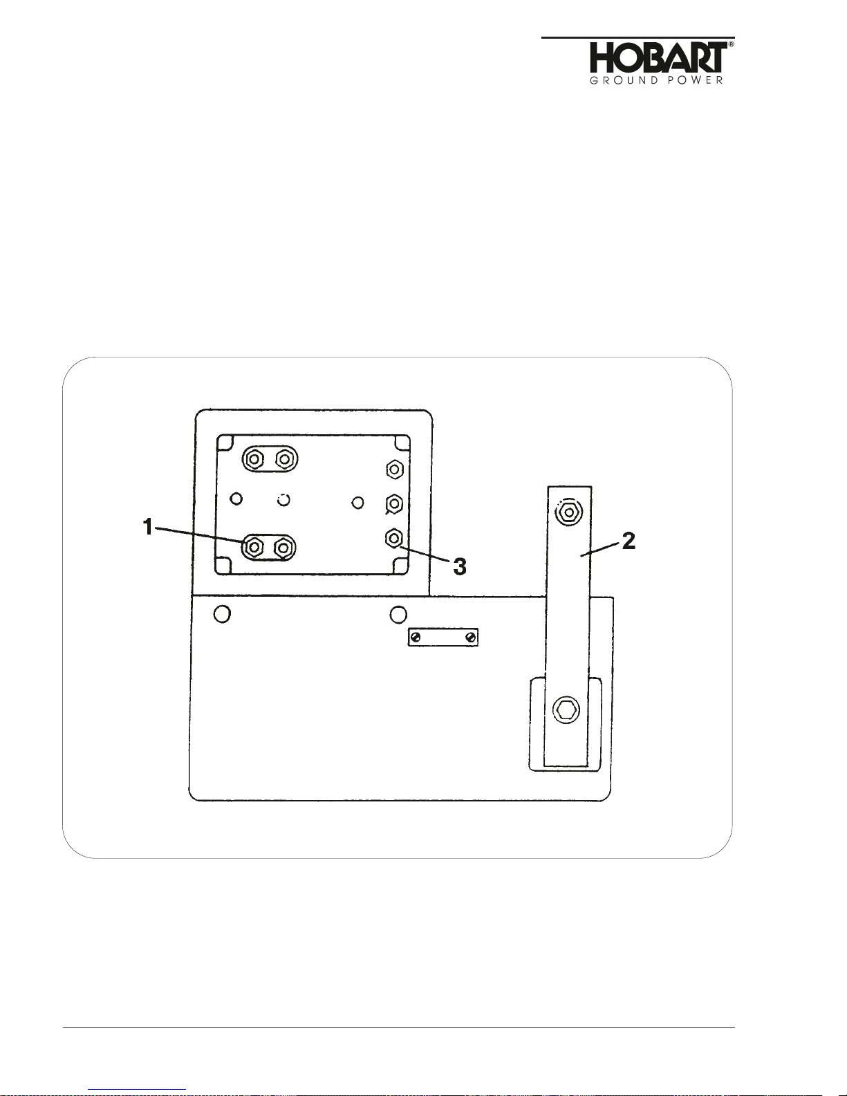
b. Cable connection
• Remove the screws that secure the lower panel (below control panel). Set the panel aside.
• Loosen the output cable clamp and thread the lugged end of the output cable through the
opening in the side of the unit.
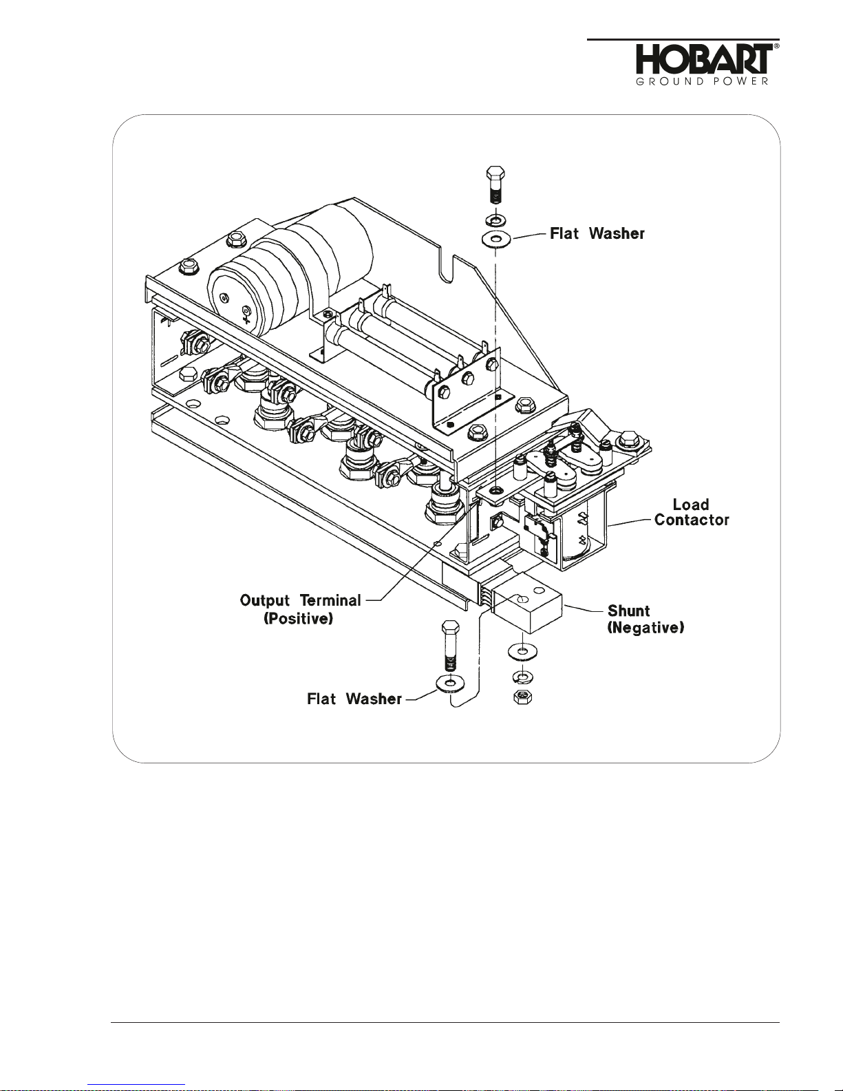
• Connect the POSITIVE cable lead to the output terminal on the contactor. Connect the
NEGATIVE cable lead to the shunt. ALWAYS place the lead under the flat washer shown.
• Tighten the cable clamp and install the lower panel.
• Store cables in cable tray provided on top of fender, or on hangers on side of canopy if
fenders are not used.
28-Volt Output Terminal Panel: Specification 7003A-3
Chapter 1-3 Dec 31/92
Page 2
1. Positive Output Connection
2. Negative Output Connectioon
3. Load Contactor
Figure 1
Page 27
OM-2063 / Operation and Maintenance Manual
Jet-Ex 4D / Spec. 7003A-3 and 7003B-3 / Generator Sets
2. Preparation for Storage
When a generator set is to be stored or removed from operation, special precautions should be taken to
protect the internal and external parts from rust and corrosion.
a. General
The unit should be prepared for storage as soon as possible after being removed from service.
Storage should be in a building which is dry and which may be heated during winter months.
Moisture absorbing chemicals are available for use where excessive packaged and sealed if
moisture absorbing chemicals are to be effective.
Dec 31/92 Chapter 1-3
Output Cable Connections: Specification 7003B-3
Figure 2
Page 3
Page 28

OM-2063 / Operation and Maintenance Manual
Jet-Ex 4D / Specs 7003A-3 and 7003B-3 / Generator Sets
b. Temporary Storage
When storing the unit for one month, prepare as follows:
(1)
Lubricate the unit completely in a ccordance with instructions in Section 2-2. This will include
changing engine oil, and filter elements.
(2)
Make certain the cooling system antifreeze solution is adequate to protect below the lowest
temperatures expected during the storage period.
(3)
Clean the exterior of the engine with fuel oil and dry with clean cloths and compressed air.
(4)
Seal all engine openings. Use a waterproof, vaporproof material that is strong enough to resist
puncture damage from air pressure.
c. Long Time Storage
(1)
Engine Protection
The Jet-Ex 4D generator set may be stored for long periods if the engine is given proper
protection from rust and corrosion. Refer to the Perkins Diesel Users Handbook (Series 4.236)
for proper procedures to be followed.
(2)
Generator Protection
To protect the generator and other electrical components, the complete unit should be packaged,
using moisture proof packaging and sealing materials. Place packages of moisture absorbing
chemicals, such as silica-gel, in the unit before packaging.
WARNING
Place warning tags in several places to make certain that the individual who
takes the unit out of storage is warned that engine oil and coolant have been
drained.
(3)
Battery Care
Remove battery and store in a cool dry place. Store the battery on wood rather than directly on
cement or metal.
3. Preparation for Shipping
Prepare the unit for shipping as follows:
• Seal all engine openings to prevent the entrance of water, dirt, and dust.
• Disconnect battery cables.
• Drain all fuel from tank and fuel lines as required by carrier rules.
• Crate the unit solidly to prevent damage to instruments, glass, and sheet metal.
Chapter 1-3 Dec 31/92
Page 4
Page 29

OM-2063 / Operation and Maintenance Manual
Jet-Ex 4D / Spec. 7003A-3 and 7003B-3 / Generator Sets
Section 4. Operation
1. General
This section contains information and instructions for the safe and efficient operation of the generator
set. Operating instructions are presented in a step-by-step sequence of procedures to be followed in
supplying power to an aircraft.
NOTE:Read ALL of the operating instructions before attempting to operate the equipment.
WARNING
Ear protection may be necessary when working close to this equipment.
2. Operating the Generator Set
a. Pre-start Inspection
(1)
Always be sure there is sufficient oil and coolant in the engine.
(2)
Be sure the fuel shutoff valve is open. The valve is located at the fuel tank outlet. Observe the
fuel gage. Make certain of sufficient fuel to complete the job to be done.
(3)
If the unit is trailer mounted and is not connected to a tow vehicle, be sure the parking brake is
applied and that the drawbar is raised and locked in the vertical position. Raising the drawbar to
the vertical position automatically applies the brakes, and they will be released when the drawbar
is lowered.
(4)
Open the engine compartment doors and inspect interior for rags, tools, and foreign material.
b. Pre-start Instructions
In all probability, the unit will be moved from one location to another many times during its lifetime of
service. Therefore, the following steps should be taken to optimize maximum efficient operation.
(1)
Check the supply of fuel, crankcase oil and radiator coolant. See Perkins Engine User’s Manual
for specifications.
(2)
Inspect the unit thoroughly to be sure it is in proper working order. Check all fuel lines and wire
connections to be certain they are secure. Tighten any loose screws, nuts or bolts.
(3)
Wipe off the entire unit and clean the air passages, control panel and other hard to reach places
with compressed air not over 25 psi
(4)
Make sure that no loose bars, tools, parts, etc., are in or on any part of the engine as they could
cause serious damage to the engine, generator, or personal injury to anyone standing nearby.
(5)
If the unit is operated indoors, make sure that an exhaust line is properly connected to the
engine exhaust system, and discharged out of doors. Avoid short bends or reduction in line sizes
in exhaust pipes. Locate the unit so as to necessitate the shortest possible exhaust line to insure
the least amount of back-pressure on the engine. Back-pressure can cause engine damage and
loss of power.
(6)
Check t he electrical system to make sure the connections are secure and properly connected.
Check t he battery electrolyte level.
(7)
Check air cleaner service indicator, and replace air cleaner element if indicator window is red.
(8)
Check the fuel/water separator and drain any water and/or solid contaminants if necessary.
(See Section 2-3, Servicing the Fuel Filter).
(172 kPa)
.
Dec 31/92 Chapter 1-4
Page 1
Page 30
OM-2063 / Operation and Maintenance Manual
Jet-Ex 4D / Specs 7003A-3 and 7003B-3 / Generator Sets
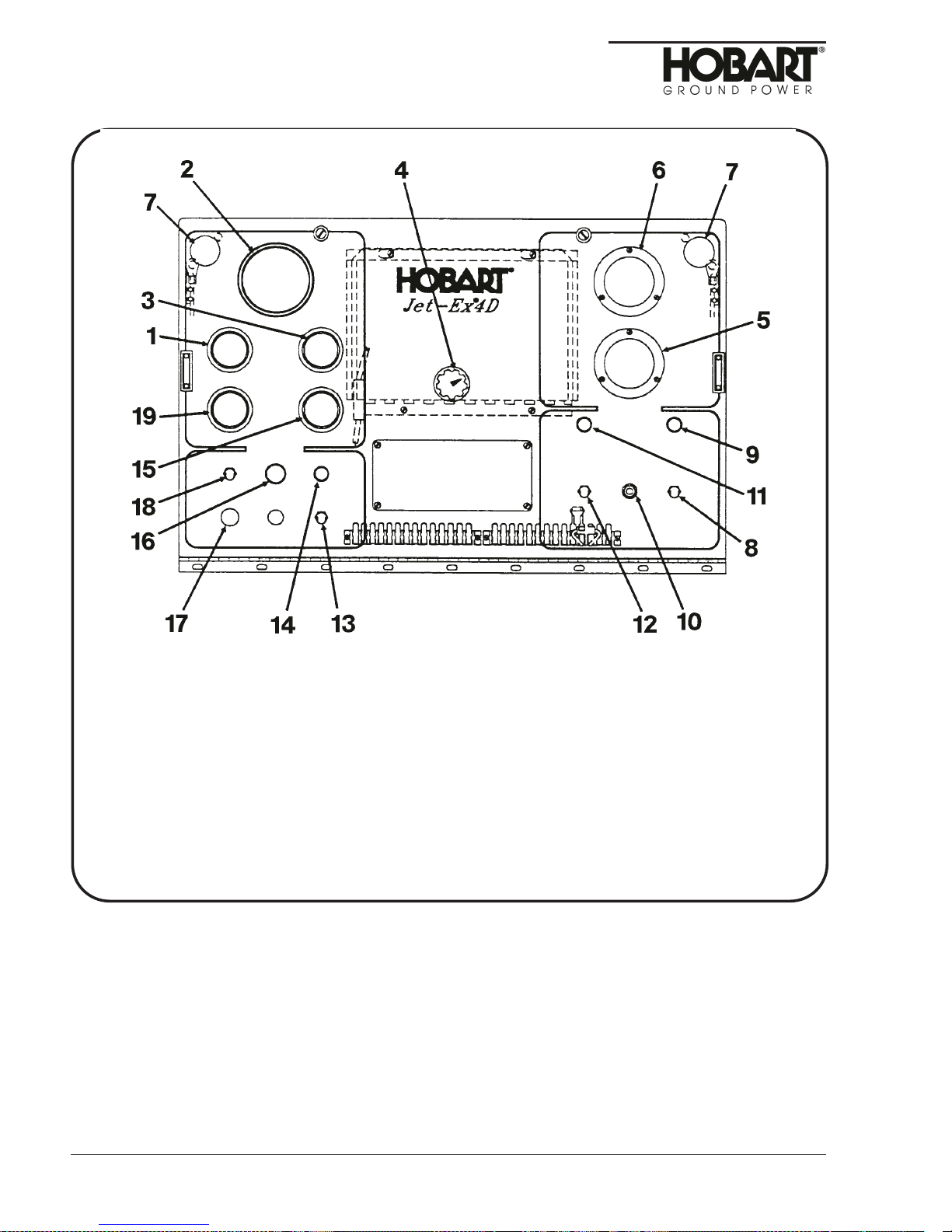
1. Oil Pressure Guage
2. Tachometer
3. Water Temperature Guage
4. Current Limit Control
5. Ammeter
(Generator)
6. Voltmeter
7. Panel Light
8. Panel Lights Switch
9. Panel Lights Fuse
11. Contactor Closed Switch
12. Contactor Closed Light
13. Speed Control Switch
14. Engine On Light
15. Hourmeter
16. Engine Control Switch
17. Engine Circuit Fuse
18. Engine Circuit
19. Ammeter
(Engine)
10. Push-To-Build-Up-Voltage Switch
Control Panel Assembly
Figure 1
c. Starting The Engine
Make sure that all Prestarting Instructions have been carried out, and reference to Initial Preparation
For Use has been checked for operating details.
NOTE:When operating in cold weather environments, read Adverse Weather Precautions before
starting the generator set.
(1)
Check engine oil, fuel and coolant levels.
(2)
Place speed control switch
(13)
in IDLE
(down)
position.
Chapter 1-4 Dec 31/92
Page 2
Page 31

OM-2063 / Operation and Maintenance Manual
Jet-Ex 4D / Spec. 7003A-3 and 7003B-3 / Generator Sets
CAUTION
If the engine stalls or falters in starting, wait three or four seconds before
re-engaging starter. This will prevent possible damage to starter or the engine.
DO NOT Operate the starter for periods longer than 15 seconds at a time. An
interval of at least two minutes should be allowed between cranking periods to
protect the starter from overheating.
(3)
Hold engine START-RUN-STOP switch (19) in START position.
(4)
Press and hold ENGINE START pushbutton (17). Release as soon as engine starts.
(5)
Release engine START-RUN-STOP switch (19) to RUN position when oil pressure builds up.
(6)
Observe engine RPM on the tachometer, and observe engine for excessive vibration. Idle speed
should be 1000 RPM + 50 RPM. If there is excessive vibration, adjust engine idle speed,
gradually increasing or decreasing it - whichever is necessary - until vibration is reduced. For idle
speed adjustment procedure, refer to Section 2-3, Para. 2,b, (4).
(7)
Allow engine to warm up before applying a load.
WARNING
The engine’ s entire exhaust system will get very hot and cause severe burns if
touched.
d. Generator Operation
(1)
Place speed control switch
(2)
Press BUILD UP VOLTAGE pushbutton
(3)
Adjust STARTING CURRENT rheostat
(4)
Deliver Power
(5)
Connect output cable to AIRCRAFT.
(6)
Hold CONTACTOR switch
CONTACTOR CLOSED light
(7)
Stop Operation Shutdown
(8)
Place CONTACTOR switch
contactor has opened and power is no longer available at the aircraft.
(9)
Place speed control switch
(10)
Disconnect output cable from aircraft receptacle and store cable in cable trays or on cable
hangers as the case may be.
(11)
Place START-RUN-STOP switch
(13)
in RATED RPM
(10)
(4)
(11)
in CLOSE position. Release to ON position as soon as green
(12)
comes on.
(11)
in OFF position. Light
(13)
in IDLE (down) position. Allow engine to run for 2 to 3 minutes.
(19)
in STOP position.
(up)
position. Engine speed will be 2000 RPM.
. Generator will produce rated voltage.
if necessary.
(12)
should go off to indicate load
e. Adverse Weather Precautions
(1)
Cold weather operation
Operation of engine-driven units at sub-zero temperatures requires special precautions and extra
servicing from both operation and maintenance personnel if poor performance or total functional
failure is to be avoided. Consult Maintenance and Operator’s Manual and recommendations
below.
(2)
Fuel system
Keep system clean and free from water which may collect in a low spot in the fuel line and
freeze, plugging the line. Fuel tanks should be kept FULL to prevent water condensation from
the air above the fuel.
Dec 31/92 Chapter 1-4
Page 3
Page 32

OM-2063 / Operation and Maintenance Manual
Jet-Ex 4D / Specs 7003A-3 and 7003B-3 / Generator Sets
(3)
Fuel
Keep fuel storage tanks or drums as full as possible to avoid condensation of moisture from the
air above the fuel. After filling or moving fuel containers, allow fuel to settle before using. Never
draw fuel from the extreme bottom of the container. Strain all fuel to remove any foreign matter.
When operating outdoors, take steps to prevent the entry of snow, water and ice into the fuel
containers.
(4)
Cooling system
Prior to cold weather, drain and flush the cooling system to remove accumulations of rust and
sediment. Mix and add antifreeze solution, check the cooling system connections for leaks. Add
a can of rust inhibitor to the radiator when system is winterized. This will keep system cleaner
and furnish lubrication for the water pump.
The engine is equipped with a water heater kit, which operates off of 115V AC, 50 or 60 cycle
line current, by plugging in the power cord located at the left, rear side of the unit. The heater is
connected to the engine cooling system between the engine block and the inlet side of the
radiator. Heated coolant is circulated through the cooling system by a thermal siphoning action.
A thermostat automatically turns the heater ON at 120°F (49°C) and OFF at 140°F (60°C).
CAUTION
DO NOT operate the heater while the engine is running. The heater is to be
used only when the engine is shut down for extended periods of time in cold
weather.
(5)
Lubrication
Drain the crankcase
Engine Oil Recommendations chart in the Perkins Engine User’s Manual for recommended
viscosity for various atmospheric temperatures. In cold weather, drain oil more frequently. Water
condenses and collects quickly, mixes with the oil and increases deposits to form a sludge.
Check oil frequently for this condition. Water in crankcase or oil lines may freeze and cause
serious damage to the oil pump, or shut off the oil supply.
(6)
Electrical system
In cold weather, the most efficient electrical system is needed to start the cold engine. Check
the entire system for loose connections or indication of bad wiring or shorted conditions.
(7)
Battery
Battery efficiency decreases sharply with lower temperatures. Maintain the specific gravity of the
battery between 1.275 and 1.300
attempting to start engine in sub-zero conditions.
f. Operation in Hot and Humid Conditions
(1)
Cooling system
Maintain a more frequent check of the coolant level in the radiator.
(2)
Battery
The specific gravity and proper level of the battery electrolyte should be maintained. Observe
recommendations in the Perkins Diesel User’s Manual for proper care of the battery.
(preferably when warm after running)
(fully charged condition)
and fill with a lighter grade of oil. See
. Make sure of full charge before
Chapter 1-4 Dec 31/92
Page 4
Page 33

OM-2063 / Operation and Maintenance Manual
Jet-Ex 4D / Spec. 7003A-3 and 7003B-3 / Generator Sets
g. Operation in Extremely Dusty Conditions
If unit is to be operated under dusty, out-of-door conditions, place in a sheltered area. Take
advantage of any natural barriers which may offer protection from blowing dust. If the installation is
more than temporary, erect a protection shield.
(1)
Fuel system
Change the fuel filter at prescribed intervals and keep fuel containers covered and protected
against dust entry.
(2)
Oil filter and air cleaner
These both need more frequent attention under dusty conditions, Check air cleaner daily.
Replace oil filter cartridge as needed.
(3)
Crankcase
The crankcase oil level will bear close attention. Dusty conditions tend to load crankcase oil with
dirt. Watch for dirty and gritty oil conditions, and change oil more frequently as required.
h. Operation in Salt Water Areas
(1)
Canopy
Wash canopy regularly to remove salt film. Repaint any damaged places and oil the side panel
hinges regularly.
(2)
Covering
To protect the engine and generator as much as possible from salt water atmosphere, keep the
side panels on the canopy closed, when not in use. It is advisable to keep the unit covered with a
tarpaulin, if available, while in operation. Salt water should be wiped from the engine, and all
terminals and connections in the electrical system wiped dry. Keep all linkage oiled.
(3)
Brushes
The brushes of the generator should be inspected regularly to make certain that they are free in
the holders. Lift the brushes in the brusholders about every two days to insure their freedom to
slide within the holder. Wipe dry all the parts that can be reached, and use compressed air, if
available, to dry the parts of the generator that cannot otherwise be reached. See
MAINTENANCE for brush care.
(4)
Field coils
The fields should be dried as thoroughly as possible. If they have become damp, proceed with
recommended procedure in MAINTENANCE section.
(5)
Battery terminals
Thoroughly clean the battery terminals and connections. Coat terminals and connections with
petroleum jelly to retard corrosion.
i. Miscellaneous
Once a month, oil hinges on the engine compartment doors and the hinged plexiglas cover.
Dec 31/92 Chapter 1-4
Page 5
Page 34

OM-2063 / Operation and Maintenance Manual
Jet-Ex 4D / Specs 7003A-3 and 7003B-3 / Generator Sets
This page intentionally left blank.
Chapter 1-4 Dec 31/92
Page 6
Page 35

OM-2063 / Operation and Maintenance Manual
Jet-Ex 4D / Specs 7003A-3 and 7003B-3 / Generator Sets
Chapter 2. Servicing/Troubleshooting
Section 1. Maintenance Inspection/Check
1. General
To make certain that generator set is always in good operating condition, it must be inspected,
maintained, and lubricated regularly and systematically.
WARNING
Stop operations at once if a serious or possibly dangerous fault is
discovered.
2. Maintenance Schedule
a. General
Figure 1 provides a suggested schedule for periodic checks and services. Refer to Section 2-2 for
lubrication requirements.
b. Maintenance Schedule Check Sheet
It is strongly recommended that the customer use a maintenance schedule check sheet. The check
sheet will provide a record of maintenance specific operation.
c. Time Intervals
The schedule is based on both hours of operation and calendar intervals. These two intervals are not
necessarily the same. The calendar period is included to make certain services are performed
regularly when equipment is being operated infrequently, or at manufacturer’s recommendations.
Perform all services on a “whichever comes first” basis.
NOTE:Refer to the Perkins Diesel User’s Manual for detailed engine maintenance information.
3. Engine and Related Components
See the Perkins Diesel User’s Manual for Series 4.236 engines.
4. Inspection and Cleaning
Every day, check for oil, coolant, or fuel leaks. Also check for loose electrical connection. Check oil
pressure with engine running at rated RPM
psi. Wipe accumulated water off from all e lectrical connections and instruments. Make sure that the
alternator ammeter is not discharging, which indicates that the battery is being charged.
Every week, wipe off accumulated dust, dirt and oil from the engine and generator. Check all parts for
loose connections and wear. If arcing has occurred at any electrical connections, recondition them and
securely refasten. Check engine oil and coolant levels.
(2000)
. Do not operate engine if oil pressure is less than 15
Dec 31/92 Chapter 2-1
Page 1
Page 36

OM-2063 / Operation and Maintenance Manual
Jet-Ex 4D / Specs 7003A-3 and 7003B-3/ Generator Sets
Recommended Service Intervals
Engine
Check oil level
Check coolant level
Check fuel quantity
Check gages and instruments for prpoer operation
Change engine oil
Change oil filter
Check and tighten drive belts
Clean and inspect exterior of radiator
Check exhuast system
Check cooling system
Check and adjust idle speed
Check and refill cooling system
Check//Replace fuel filter
Clean engine
Electrical System (12V DC)
Check lights
Check charging rate
Check battery water level
Check battery state of charge
Check wiring and connections
Check all instruments and gages
Check battery terminals and connectors
Electrical system (28.5V DC)
Check indicating light
Check operation of all instruments, meters, etc.
Check generator brushes for length, cleanliness
andfreeoperation
Check slip rings for smoothness and clealiness
Check the entire unit
Check overvoltage protection
Check all wiring connections
Trailer (Option)
Lubricate
Check tire inflation
Check and adjust wheel bearings
Lubricate wheel bearings
Check brake tension
10 hrs.
or
Daily
XX
100 hrs.
or
2 Weeks
X
X
X
X
X
(Twice yearly, summer and winter)
X
X
X
200 hrs.
or
1 Month
X
X
400 hrs.
or
2 Months
X
X
X
X
800 hrs.
or
6 Months
X
X
X
X
X
X
X
X
X
X
X
X
X
X
X
X
X
Inspection/Check/Maintenance Schedule
Chapter 2-1 Dec 31/92
Page 2
Figure 1
Page 37

OM-2063 / Operation and Maintenance Manual
Jet-Ex 4D / Specs 7003A-3 and 7003B-3 / Generator Sets
Every month, check generator for amperage and voltage output. Blow out generator windings with
compressed air, not over 25 psi
(172 kPa)
pressure or remove with a suction-type cleaner with a
non-metalic nozzle. If windings should become slightly damp, use space heaters or electrical light bulbs
to effectively dry out the windings. If dampness is excessive, apply external heat under a canvas cover,
well vented. Heating should not exceed 194
o
F
(90oC)
.
Pound out any dents in the canopy. Sand, prime, and repaint any dented or rusted spots.
Dec 31/92 Chapter 2-1
Page 3
Page 38

OM-2063 / Operation and Maintenance Manual
Jet-Ex 4D / Specs 7003A-3 and 7003B-3/ Generator Sets
This page intentionally left blank
Chapter 2-1 Dec 31/92
Page 4
Page 39

OM-2063 / Operation and Maintenance Manual
Jet-Ex 4D / Spec. 7003A-3 / Generator Sets
Section 2. Troubleshooting Procedures
1. General
Troubleshooting is an orderly process of checking and eliminating possible causes of trouble until the
exact cause of a trouble is found. As a rule, the best place to start looking for the cause of a trouble in a
circuit is at the source of power. Continue testing and checking the circuit, step-by-step, in an orderly
manner, until the cause of trouble is located. See connection and schematic diagrams.
2. Troubleshooting Chart
a. Description
The troubleshooting chart lists information under three headings:
(1)
Trouble, symptom, and condition,
(2)
Probable cause
(3)
Test, check and remedy
b. Use of the Troubleshooting Chart
Read the trouble symptoms and conditions before proceeding to causes and remedies. For example,
at the beginning of the troubleshooting chart under ENGINE, the first trouble listed is: “Engine will not
start. Starter will NOT crank engine.” If the starter WILL crank the engine, then obviously this is not
your symptom and condition. Go the next trouble and symptom directly below. If the starter will NOT
crank the engine, look to the right under PROBABLE CAUSE and TEST, CHECK, AND REMEDY
and find the various things which could cause the trouble and what to do to check and remedy them.
3. Equipment for Troubleshooting
A good quality, multi-scale voltmeter is the only instrument required similar clips, will be required. The 12
volt engine electrical system may be used for a 12 volt DC power source.
WARNING
Loose garments, neckties, and other hanging items must not be worn by
personnel near the fan or other exposed moving parts of this equipment while it
is running. Also, avoid contact with live electrical parts. Death or serious injury
could result!
4. Diagrams
For each of the the generator sets covered by this manual an electrical schematic and connection
diagram is provided in the Manufacturers Literature chapter of this manual. These diagrams can be
very helpful in troubleshooting. Components shown in the diagram are identified by reference
designators
reference designator by its full item name. For example, the symbol K403 identifies the overvoltage
relay, and M406 identifies the voltmeter.
(or item names in some instances)
. A legend appearing on the diagram identifies each
5. Illustrations
To aid maintenance personnel with troubleshooting, three illustrations are provided in this section,
showing the locations of various components of the generator set.
6. Connections and Wiring
Before condemning any electrical component, check all connections and wiring which could affect its
operation. In many instances a component may be non-functional simply because it is not receiving
power because of a loose connection or a poor ground. In most cases throughout the troubleshooting
chart, it will be assumed that connections and wiring have been checked.
Dec 31/92 Chapter 2-2
Page 1
Page 40

OM-2063 / Operation and Maintenance Manual
Jet-Ex 4D / Spec. 7003A-3 and 7003B-3 / Generator Sets
1. Radiator
2. Air cleaner
3. Muffler
4. Engine
5. Lifting yoke
6. Rectifier assembly
7. Fuel tank
8. Control panel
9. Generator
Chapter 2-2 Dec 31/92
Page 2
10. Fuel filter
11. Throttle control solenoid
12. Oil filter
13. Drain cock & switch
14. Load contactor
15. Batteries
16. Alternator
17. Fuel filter
18. Starter
Generator Set Components
Figure 1
19. Starter relay
20. Frame
21. Fuel tank support
22. Engine governor
23. Water temperature
sender
24. Oil pressure sender
Page 41

OM-2063 / Operation and Maintenance Manual
Jet-Ex 4D / Spec. 7003A-3 / Generator Sets
1. Oil Pressure Guage
2. Tachometer
3. Water Temperature Guage
4. Current Limit Control
5. Ammeter
6. Voltmeter
7. Panel Light
8. Panel Lights Switch
9. Panel Lights Fuse
10. Push-To-Build-Up-Voltage Switch
Dec 31/92 Chapter 2-2
(Generator)
Control Panel Assembly
Figure 2
11. Contactor Closed Switch
12. Contactor Closed Light
13. Speed Control Switch
14. Engine On Light
15. Hourmeter
16. Engine Control Switch
17. Engine Circuit Fuse
18. Engine Circuit
19. Ammeter
(Engine)
Page 3
Page 42

OM-2063 / Operation and Maintenance Manual
Jet-Ex 4D / Spec. 7003A-3 and 7003B-3 / Generator Sets
Chapter 2-2 Dec 31/92
Page 4
1. Excitation Rectifiers
2. Voltage Sensing Relay
3. Overvoltage Relay
4. Voltage Regulator
5. Voltage Regulator Fuse
Voltage Regulator Support
Figure 3
Page 43

OM-2063 / Operation and Maintenance Manual
Jet-Ex 4D / Spec. 7003A-3 / Generator Sets
Engine and Controls
Trouble, Symptom and Condition Probable Cause Test, Check, and Remedy
1. Engine will not start. Starter
will not crank engine.
a. Batteries discharged, sure
this voltage is reaching or
loose battery or ground
connection.
b.Engine push button start
switch
c. Defective starter relay
(L401)
(S401)
.
defective.
Check battery connections and
check voltage across battery.
Voltage should be approximately
12.8 VDC. starter relay input
terminal. If battery and
connections are good, proceed
to Step b.
Momentarily connect a jumper
between the hot side of the
starter relay
start switch terminal on the
starter relay (yellow-blue) wire.
If the starter operates, check
pushbutton start switch
2)
. Replace faulty switch. If
starter doesn’t crank, proceed
to Step c.
Momentarily connect a large
capacity jumper cable between
the hot side of the starter relay
(19, Fig. 1)
terminal. If the starter attempts
to crank the engine, the starter
solenoid is defective. Replace
it. If engine still won’t crank,
proceed to Step d.
(L401)
and the
(17, Fig.
and the starter input
d.Defective starter
e. Internal engine seizure.
(B401)
. If starter did not attempt to
operate in Step C above, the
starter is defective. Replace
starter. If starter did attempt to
operate, but couldn’t turn
engine, proceed to Step e.
CAUTION:Make certain that
engine start switch is
in “stop” position so
that engine does not
start.
Useasocketwrenchonthe
front crankshaft pulley to try to
turn engine by hand. If engine
will not turn, internal damage is
indicated.
Dec 31/92 Chapter 2-2
Page 5
Page 44

OM-2063 / Operation and Maintenance Manual
Jet-Ex 4D / Spec. 7003A-3 and 7003B-3 / Generator Sets
Engine and Controls (continued)
Trouble, Symptom and Condition Probable Cause Test, Check, and Remedy
Engine wll not start. Starter
will not crank engine
(continued).
2. Engine will not start. Starter
DOES crank engine.
a. Engine circuit fuse
blown -or-
b.Fuel valve at tank closed,
or no fuel in tank, engine
has lost its prime -or-
c. Defective engine start
switch
d.Defective fuel valve
solenoid
e. Defective fuel pump.
(S404)
(L404)
(F402)
-or-
.
NOTE:If engine is overcharged
with ether for cold weather
starting, it could seize up.
If so, wait approx. 1/2 hour
until it will be possible to
turn engine.
Replace engine circuit fuse
. Use type AGC-2O fuse.
Fig. 2)
Check and correct as required.
Check f or 12-V DC from
terminal 4 of S404 in “START”
position. If 12-V DC is not
measured, replace defective
switch.
Attempt to start engine while
applying 12-V DC to the fuel
valve solenoid. If the engine
starts, the solenoid is defective,
and should be replaced. If
engine still doesn’t start,
proceed to Step e.
Check f uel pump according to
instructions in the Perkins
Diesel User’s Manual.
(18,
3. Engine starts then stops. a. Fuel not turned on.
4. Engine starts then stops when
engine switch
released to “ON” position.
Chapter 2-2 Dec 31/92
Page 6
(S404)
is
b.Defective oil pressure
switch
engine block.
a. Open overtemperature
switch
engine switch
(S403)
(S402)
located on
or defective
(S404)
Turn on fuel shutoff valve.
Connect a jumper wire across
the “C” and “No” terminals of oil
pressure switch. Start engine
and check oil pressure. If it is
below 10 PSI
down the engine and check
lubrication system for leaks.
Check also the oil pump. If oil
pressure comes up to normal
and the engine continues to
run, the oil pressure switch is
defective. Replace oil pressure
switch.
Place a clip-lead jumper wire on
the water temperature switch
.
terminals and check for normal
operating temperature. If engine
then starts properly, replace
water temperature switch. If
not, replace engine switch.
(69 kPa)
shut
Page 45

OM-2063 / Operation and Maintenance Manual
Jet-Ex 4D / Spec. 7003A-3 / Generator Sets
Engine and Controls (continued)
Trouble, Symptom and Condition Probable Cause Test, Check, and Remedy
Engine starts then stops when
engine switch
released to “ON” position
(S404)
is
(continued).
5. Engine does not attain normal
idle RPM, or idles too fast.
6. Engine will not run at rated
(2000 RPM)
speed
b.Choked fuel filter, restriction
in air cleaner, or air in fuel
system.
a. Idle speed set either too
high or too low.
b.Loose throttle linkage
c. Defective full throttle
(L403)
solenoid
a. Speed control switch
(S406) defective.
.
Check for these faults according
to instructions in Perkins Diesel
User’s Manual.
Adjust idle speed to
approximately 1000
If solenoid core is pulled into
the full throttle solenoid
when S406 is in RATED RPM
position, check for loose control
rod between solenoid and
throttle. Tighten if required. If
solenoid core does not pull in,
proceed to Step c.
Check for l2-V-DC across two
terminals of solenoid when
S406 is in RATED RPM
position. If l2-V DC is
measured, but solenoid core
does not pull in, replace the
solenoid.
If engine will not go from idle to
rated speed when speed
control switch
RATED RPM position, turn off
engine and take resistance
measurements at speed control switch
terminalswithswitchinthe
RATED SPEED position.
+
50 RPM.
(13, Fig. 2)
(L403)
is in
7. Engine lacks power. a. Insufficient air to engine.
Dec 31/92 Chapter 2-2
b.Restricted exhaust system.
c. Low compression.
Zero resistance should be
measured between terminals
having red-blue and orange
yellow wires. Replace speed
control switch if measurement is
improper.
Check and service air cleaner
for clogged condition. Replace
as required.
Check exhaust pipe for
restrictions. Check muffler for
clogged condition. Replace as
required.
Check compression in all
cylinders according to Perkins
Engine User’s Manual.
Page 7
Page 46

OM-2063 / Operation and Maintenance Manual
Jet-Ex 4D / Spec. 7003A-3 and 7003B-3 / Generator Sets
Engine and Controls (continued)
Trouble, Symptom and Condition Probable Cause Test, Check and Remedy
8. Engine Overheats. a. Dirt or sludge in Coolant Drain coolant, flush radiator, put
in clean coolant. Refer to
Perkins Engine User’s Manual
in Chapter 5 for instructions.
b.Debris and dirt in radiator
core.
c. Fan belt slips or is broken.
Clean radiator core carefully.
Refer to Perkins Engine
User’s Manual.
Tighten belt or replace as
required
Chapter 2-2 Dec 31/92
Page 8
Page 47

OM-2063 / Operation and Maintenance Manual
Jet-Ex 4D / Spec. 7003A-3 / Generator Sets
Generator and Controls
Trouble, Symptom and Condition Probable Cause Test, Check, and Remedy
1. Generator will not build up
voltage at all when
push-to-build-up voltage switch
(S407)
running normally.
is operated. Engine
a. Flashing power not
reaching generator
(L406)
revolving field
b.Defective
push-to-build-up-voltage
switch
stuck in open position
c. Defective diode
d.Excessive brush wear, or
poor contact of brushes to
slip rings.
e. Voltage sensing relay
(K406)
contact 1-7 or 3-9 stuck in
open position
(S407)
defective. Relay
.
contacts
(CR401)
Check as follows:
Momentarily connect two
jumper leads across the
push-to-build-up-voltage switch;
one lead across the terminals
on the left side and the other
lead across the terminals on the
right side. If the voltage builds
up, replace switch.
Useohmmetertocheckdiode
on back of push-to
-build-up-voltage switch.
Replace diode if defective.
Check brushes closely for
excessive wear and check
brush contact with slip rings.
Replace brushes make sure
that brush contact with slip rings
is proper.
Connect a jumper lead between
pins 1 and 3 on voltage sensing
(2, Fig. 3)
relay
builds up when switch S407 is
pushed, voltage sensing relay is
defective and must be replaced.
If voltage sensing relay is good,
proceedtoStepf.
. If voltage then
CAUTION
DO NOT operate the generator set
to deliver power to an aircraft when
any protective device or other
component is jumpered.
Dec 31/92 Chapter 2-2
f. Generator revolving field
(L406)
defective.
Locate yellow and red-orange
wires on the right terminal strip
at lower rear of control panel.
Disconnect the yellow and
red-orange wires which go
down to the generator.
(Refer to
connection diagram 180435
Chapter 5)
Measure resistance between
thesetwowiresshouldbe6to
8 ohms. If reading indicates an
open, short or lower than
normal resistance, proceed to
Step g.
.
Page 9
Page 48

OM-2063 / Operation and Maintenance Manual
Jet-Ex 4D / Spec. 7003A-3 and 7003B-3 / Generator Sets
Generator and Controls (continued)
Trouble, Symptom and Condition Probable Cause Test, Check, and Remedy
Generator will not build up
voltage at all when
push-to-build-up voltage switch
(S407)
running normally (continued).
2. Generator builds up to only a
low voltage while
push-to-build-up voltage.
Switch is depressed.
3. Generator builds too high a
voltage.
is operated. Engine
g. Defective generator
armature
a. Generator voltage regulator
fuse
b.Defective control winding
rectifier
c. Generator voltage regulator
(VR4O2)
a. Defective voltage regulator
(VR4O2)
(G402)
(F403)
defective.
.
blown.
If check of the generator
revolving field
revealed no trouble, the
generator stator is defective.
Send unit to overhaul.
Replace voltage regulator fuse
(5, Fig. 3)
generator set to see if problem
is corrected. If not, proceed to
Step b.
Check control winding rectifiers
(3, Fig. 3)
see if they are good. If either
rectifieris defective, replace it.
If both rectifiers are good,
proceed to Step c.
Replace voltage regulator
(1, Fig. 3)
Replace voltage regulator
Fig. 3)
known to be good, and resume
operation of generator set. If
new voltage regulator produces
normal operating voltage, send
old voltage regulator to factory
for service.
with a voltage regulator
(Step f. above)
. Resume operation of
with an ohmmeter to
.
(2,
4. Load contactor will not close
when contactor close
(S408)
switch
Engine running normally,
voltage normal, no load
applied to output cable.
is operated.
a. Defective contactor close
(S408)
switch
b.Defective load contactor
(K402)
.
c. Overvoltage relay
defective.
.
(K403)
Momentarily connect a jumper
lead between terminals 4 and 5
(red and yellow-red wires)
the contactor close switch
Fig. 2)
. If the load contactor
closes momentarily, replace
contactor close switch.
If load contactor
not close when contactor close
switch is jumpered, it is likely
that the contactor is defective.
Replace contactor.
Connect a jumper lead between
terminals T and P on the
overvoltage relay
contactor will now close,
replace overvoltage relay.
(14, Fig. 1)
(2,Fig.3)
on
(11,
will
.If
Chapter 2-2 Dec 31/92
Page 10
Page 49

OM-2063 / Operation and Maintenance Manual
Jet-Ex 4D / Spec. 7003A-3 / Generator Sets
Generator and Controls (continued)
Trouble, Symptom and Condition Probable Cause Test, Check, and Remedy
5. Load contactor opens as soon
as contactor close switch is
released from its top
(spring-loaded)
6. Load contactor opens during
power delivery.
position
a. Defective contactor close
(S408)
switch
b.Defective resistor R406
.
(located in back of control
panel, on right terminal strip
at bottom of panel. See
connection diagram
180435)
c. Defective diode
d.Load contactor
defective.
a. Contactor opening could
have been normal because
of an overvoltage condition.
.
(CR4O2)
(K402)
Connect a jumper lead between
terminals 1 and 2
and yellow-red wires)
contactor close switch
2)
. If the load contactor now
remains closed, replace
contactor close switch.
Using an ohmmeter, check
resistor R406 for proper
resistance
open circuit is indicated, replace
resistor.
. This diode is also located on
the right terminal strip at bottom
rear of the control panel. Using
an ohmmeter, check this diode
for an open circuit. If diode is
defective, replace it.
If no fault was found in steps
4-a, b, and c above, the load
contactor
defective. Replace load
contactor.
Resume operation and closely
observe voltmeter
evidence of overvoltage.
(7.5 ohms)
(22, Fig. 1)
contactor opens
overvoltage condition exists,
proceed to Step b.
(orange-red
on the
(11, Fig.
.Ifan
is
(6, Fig. 2)
If
when no
for
Dec 31/92 Chapter 2-2
Page 11
Page 50

OM-2063 / Operation and Maintenance Manual
Jet-Ex 4D / Spec. 7003A-3 and 7003B-3 / Generator Sets
Generator and Controls (continued)
Trouble, Symptom and Condition Probable Cause Test, Check, and Remedy
Load contactor opens during
power delivery.
7. Output current cannot be
limited by operating current
limiting potentiometer
(continued)
b.Overvoltage relay
defective.
c. Overvoltage board out of
adjustment.
d.Load contactor
defective.
a. Defective current limiting
potentiometer
(K403)
(K402)
(R402)
Check overvoltage relay by
operating the machine under
load and gradually raising
voltage at the voltage regulator
(4, Fig. 3)
voltmeter
low voltage
gradually increase voltage until
relay functions to open load
contactor.
If relay trips at less than 32-V
DC, adjust potentiometer (P1)
on the overvoltage board
(3, Fig. 3)
correct problem, return old
board to factory for service.
If no fault was found in Step b
or c, replace load contactor
while observing
(6, Fig. 2)
(25V DC)
. If this does not
. Start with a
and
(14, Fig.1)
Shut down engine and check
current limiting potentiometer
(4, Fig. 2) with an ohmmeter.
To do this, disconnect the plug
(P404) from the regulator board
(4, Fig. 3) and take resistance
measurements from pin 2 to pin
9 and then from pin 2 to pin 10
on the plug. For each measurement, slowly turn potentiometer
through its entire range, while
observing the ohmmeter
readings. Resistance should be
from 0-10kΩ. Replace if
necessary. If it isn’t defective,
proceed to Step b.
Chapter 2-2 Dec 31/92
Page 12
b.Defective voltage regulator
(VR4O2)
.
Replace voltage regulator with
one known to be good, and
then operate the generator set
under sufficient load to observe
current limiting. If current
limiting potentiometer now
controls current properly, send
old voltage regulator to factory
for service.
Page 51

OM-2063 / Operation and Maintenance Manual
Jet-Ex 4D / Spec. 7003A-3 and 7003B-3 / Generator Sets
Section 2. Maintenance Procedures
1. General
A suggested Maintenance Schedule is provided in Section 1 of this Chapter. Each step of the schedule
is also covered in general in Section 1. This Section covers maintenance in more detail where
necessary.
WARNING
Stop operation immediately if a serious or possibly dangerous fault is discovered.
2. Lubrication
a. General
Proper lubrication is one of the most important steps in good maintenance procedure. Proper
lubrication means the use of correct lubricants and adherence to a proper time schedule. Lubrication
points, frequency of lubrication, and recommended lubricants
b. Lubrication Chart
Lubrication points are illustrated and identified by name on Lubrication Chart, Figure 1. Number
symbols used to designate the kind of lubricant required and the specification recommended are
identified in Figure 2. Letter symbols used to designate the normal lubrication period are identified in
Figure 3.
c. Generator
The 28.5 volt DC generator requires NO lubrication. The armature is sealed at the factory for lifetime,
maintenance free operation. The front end of the armature is supported by the engine main bearings.
d. Generator Controls
Generator controls and instruments require no periodic lubrication. A few drops of oil may be
required on door hinges occasionally to insure free and quiet operation.
e. Engine
Although the engine and its accessories require no more attention than any other similar installation,
they still inherently require a major portion of the generator set lubrication and maintenance.
Recommendations regarding engine lubrication have been taken from the Perkins Diesel Users
Manual for Series 4.236 engines.
(1)
Lubrication Schedule
Time schedules indicated on the Lubrication Chart, Figure 1, are approximate. They are based
on average operating conditions. It may be necessary to lubricate more frequently under severe
operating conditions such as: low engine temperature, high oil temperature, intermittent
operation, or dusty conditions. However, time intervals should not exceed those indicated in the
chart without careful evaluation.
(2)
Oil Specification
The use of quality lubricating oil, combined with proper oil drain and filter change intervals are
important factors in extending engine life. Lubricating oils must be equal to the U.S. Ordnance
specification MIL-L-46152 or MIL-L-2104C. Lubricating oils for use in Perkins diesel engines
must have a minimum viscosity index of 80.
(3)
Oil viscosity
Always insure that the correct viscosity grade of lubricating oil is used for the temperature range
in which the engine will operate as shown in Figure 3.
Jan 10/91 Chapter 2-3
Page 1
Page 52

OM-2063 / Operation and Maintenace Manual
Jet-Ex 4D / Spec. 7003A-3 and 7003B-3 / Generator Sets
(4)
Change lubrication engine oil (100 hours)
Oil should be changed after each 100 hours of engine operation. The generator set is equipped
with an hourmeter which records actual engine operating time. The ideal time to change oil is
soon after a power delivery run when the engine is at operating temperature.
NOTE:If lubricating oil is drained immediately after the unit has been run for some time, most of the
sediment will be in suspension in the oil and will drain without clinging to the internal surfaces.
Chapter 2-3 Dec 31/92
Page 2
Lubrication Chart
Figure 1
Page 53

OM-2063 / Operation and Maintenance Manual
Jet-Ex 4D / Spec. 7003A-3 and 7003B-3 / Generator Sets
Symbol Name Specification Notes
1 Grease, Automotive and
Industrial
2 Oil, Engine, Heavy Duty MIL-L-46152 or
3 Grease, Automotive Military MIL-G-10924B Wheel bearings
Ambient Temperature Range Viscosity #
0F(-18C)to30F(-1C) 10W
30 F (-1 C) to 80 F (27 C) 15W/40
Above80F(27C) 15W/40
Temperature and Oil Viscosity Chart
Federal VV-G-632 Sinclair LItholene Industrial
No.2; Mobile-Mobilplex 47
or equivalent.
See Perkins Engine User’s
MIL-L-2104C
Lubricants
Figure 2
Figure 3
Handbook for
recommended oil viscosity
CAUTION
(5)
Change oil as follows:
a.
b.
c.
d.
Symbol Time Interval
D 10 hours or Daily
BW 100 hours or Biweekly
M 200 hours or Monthly
BM 400 hours or Bimonthly
SA 800 hours or Semiannually
Symbols and Time Intervals
Figure 4
DO NOT use solvents as flushing oils in running engines.
Provide a container for catching used oil. Capacity should be greater than 2 gallons.
Remove drain plug located in oil pan. Allow sufficient time for oil to drain from valve train,
timing gear case, etc., before reinstalling plug.
Change oil filter while oil is draining, see Para. 2, E, (5) below.
Clean drain plug and reinstall. DO NOT over-tighten.
Jan 10/91 Chapter 2-3
Page 3
Page 54

OM-2063 / Operation and Maintenace Manual
Jet-Ex 4D / Spec. 7003A-3 and 7003B-3 / Generator Sets
e.
Remove filler cap on valve cover and refill crankcase with new, clean oil of proper
specification and viscosity, (
filter is changed.
f.
Start engine and allow it to idle. Oil pressure should come up to normal quickly. Check for oil
leaks at filter and drain plug.
g.
Stop engine. Allow several minutes for oil to drain to crankcase, then check oil level. It should
be at FULL mark on dipstick.
h.
Check hourmeter and record time of oil change.
i.
Change engine oil filter (100 hours)
j.
Place a container under the oil filter to catch oil drippings.
k.
Loosen filter with a special oil filter removal wrench. Several types are available. Discard oil
filter.
l.
Coat the gasket on the new filter with oil.
m.
Place the new filter in position on the cylinder block and spin on until the gasket contacts the
adapter face; then hand tighten another 1/2 turn. Do not over-tighten.
n.
Start engine and check filter gasket for leaks.
see Para. 2, E, (2) and Figure 4)
7 quarts are required when oil
3. Servicing the Air Cleaner
Refer to Figure 5. The air cleaner is a dry type with replaceable filter cartridges. A definite time schedule
for changing the filter cartridge cannot be determined because of varying operating conditions. Change
the filter cartridge when the red indicator “flag” becomes fully visible in the viewing chamber
locks in that position. Change the cartridge as follows:
(9)
and
a. Cartridge Removal
(1)
Open left front canopy door to gain access to the air cleaner.
(2)
Remove clamp assembly from air cleaner, and remove cup assembly with the baffle.
(3)
Remove wing nut and washer gasket.
(4)
Remove cartridge, and replace it with a new cartridge.
Air Cleaner Cartridge Replacement
Chapter 2-3 Dec 31/92
Page 4
Figure 5
Page 55

OM-2063 / Operation and Maintenance Manual
Jet-Ex 4D / Spec. 7003A-3 and 7003B-3 / Generator Sets
CAUTION
DO NOT attempt to clean or re-use the old air cleaner cartridge.
(5)
Inspect the interior of the cleaner housing. Make certain that it is free from all foreign material.
b. Cartridge Installation
(1)
Carefully install the new cartridge into the housing. Avoid bumping the cartridge tubes against
the housing sealing flange. Seat the cartridge properly within the housing. Press all edges and
corners of the cartridge firmly with fingers to make a positive air seal against the sealing flange of
the housing.
CAUTION
UNDER NO circumstances should the cartridge be pounded or struck in the
center to affect a seal.
(2)
Lock t he cartridge in place with the washer gasket and the wing nut. Then install the baffle into
(3)
the cup assembly and fasten it to the end of body with clamp. Tighten clamp
down in place.
4. Servicing the Fuel Filter
Refer to Perkins Diesel User’s Handbook in Chapter 6 for instructions on removal and replacement of
fuel filter elements. The glass bowl on the fuel/water separator should be checked daily for the
presence of water or solid contaminants and drained.
a. Draining the Fuel/Water Separator Bowl
(1)
Place a suitable container, large enough to hold a pint of fluid, under the separator bowl.
(2)
Loosen the vent cap.
(3)
Loosen the drain valve. It is not necessary to remove it. Close the drain valve when the bowl is
empty.
(4)
Reprime the unit by loosening the primer
pump knob and lifting it up and down.
Continue priming until fuel purges from the
vent. Tighten the pump knob and vent cap.
b. Replacing the Filter Element
(1)
Place a container, large enough to hold a
pint of fluid, under the filter.
(2)
Loosen the vent cap and drain valve to
drain fuel from the the filter assembly.
(3)
Remove the filter element with the drain
bowl attached.
(4)
Separate the drain bowl from the filter
element. Properly dispose the filter
element.
(5)
Clean the bowl, o-ring groove and o-ring.
(6)
Lubricate the o-ring and the gasket on top
of the new filter element with clean diesel
fuel.
(7)
Place the o-ring in the groove in the top of
the glass bowl, then attach the glass bowl
to the filter element.
Fuel/Water Separator
Figure 6
Jan 10/91 Chapter 2-3
Page 5
Page 56

OM-2063 / Operation and Maintenace Manual
Jet-Ex 4D / Spec. 7003A-3 and 7003B-3 / Generator Sets
(8)
Spin the bowl/element assembly back onto the filter head.
(9)
Loosen the pump knob and prime the filter until fuel purges from the vent.
(10)
Close the pump knob and vent cap.
5. Drive Belt Service
Check all drive belts and adjust if necessary each 200 hours. Refer to Perkins Diesel User’s Manual in
Chapter 6 for proper procedures.
6. Engine Cooling System
NOTE:Refer to the Perkins Diesel User’s Manual in Chapter 6 for detailed instructions on servicing the
engine’s cooling system.
During warm weather operation, when plain water is used as a coolant, the cooling system MUST be
protected against rust by a rust inhabiter additive. During cold weather operation the system MUST be
protected against freezing. The system should NEVER be operated on plain water, without a rust
inhabiter or antifreeze.
WARNING
When removing the cap from a very hot radiator, cover the cap with a thick cloth
and turn it slowly counterclockwise to the first stop. When pressure is
completely released, press downward and finish removing cap.
CAUTION
DO NOT add coolant to an extremely hot engine. This can result in a cracked
block or cylinder head.
a. Rust Inhibitor
Use only a corrosion inhibitor that is compatible with aluminum. Do not use inhibitors labeled as “acid
neutralizer”.
b. Antifreeze
A permanent type
coolant, when mixed as equal parts of water and the recommended antifreeze, will provide protection
to -35 degrees F.
(Ethylene Glycol)
antifreeze is recommended for use in the cooling system. The
7. Battery Service
a. General
Two 12-volt batteries connected in parallel supply power for operation of the engine electrical
system, clearance and panel lights, and for flashing the generator.
b. Battery Location and Accessibility
The battery is located in a tray directly beneath the cooling fan at the front of the unit. These battery
is easily accessible for service by removing two 1/4-inch wing nuts and lifting out the battery access
panel at the bottom front of the unit.
c. Battery Care
(1)
Never allow a battery which has been removed from a unit to sit on concrete, ground, or metal,
unless proper insulation is provided. A wooden platform or board will provide sufficient insulation.
(2)
Maintain stored batteries in a charged condition,
(3)
Be sure the battery is fastened securely in the compartment to avoid damage from vibration.
(4)
Maintain battery fluid at proper level.
Chapter 2-3 Dec 31/92
Page 6
Page 57

OM-2063 / Operation and Maintenance Manual
Jet-Ex 4D / Spec. 7003A-3 and 7003B-3 / Generator Sets
(5)
Keep battery terminal posts and lead cable connectors clean.
WARNING
Never allow sparks or open flame near batteries. avoid spilling electrolyte on
hands or clothing.
d. Liquid Level
The electrolyte in each cell should be above the plates at all times to prevent battery failure.
Check t he level of the electrolyte every two weeks. When electrolyte level is low, add pure
distilled water. Do not use hydrant water or any water which has been in contact with a metal
container. Acid should never be added except by a skilled battery man.
CAUTION
Never add any special battery dopes, solutions, or powders.
NOTE It is especially important to keep the battery at full charge for cold weather operation. Add distilled
water to the battery in freezing temperatures only when the engine is to operate for several hours, to
thoroughly mix the water and the electrolyte, or damage to the battery will result from the water
freezing.
e. Cleaning the Battery
If the top of the battery is dirty, they may be cleaned with a brush dipped in ammonia or soda
solution. Disconnect lead connectors from battery posts. Vent plugs should be tightened to prevent
cleaning solution from entering cells. Clean battery as required, using brush and cleaning solution.
Flush off the batteries with clean water. Special terminal cleaning tool. Make certain that vent holes
in filler caps are not clogged.
f. Testing a Battery
Tests are made on a battery to determine the state of charge and also its condition. The results of
these tests show whether the battery is good, needs recharging, or must be replaced. If a battery has
failed, is low in charge, or requires water frequently, the reason for the condition must be found and
corrected. Visually inspect the battery before testing, to determine if it has been damaged. Moisture
on the outside of the case, or low fluid level in one or more cells indicates possible battery damage
(cracked case, etc.)
used to determine the battery’s ability to deliver current. A battery hydrometer test determines the
charge condition of the battery.
• Test with Battery-Starter Tester
Connect battery to the tester according to instructions furnished with the instrument. Test battery
according to tester instructions. If the test determines that the battery has acceptable voltage,
this indicates that the battery has output capacity and will accept a charge if required.
• Test with Hydrometer
a.
Remove filler caps and check the specific gravity of the electrolyte in each cell. If specific
gravity is 1.230 or below, add water if necessary and charge the battery until it is fully
charged. A fully charged battery will give a specific gravity reading of 1.265 to 1.285. The
specific gravity of a fully discharged battery may range from 1.140 down to 1.120.
. The battery may be tested by two methods. A battery-starter Tester may be
NOTE:The battery is fully charged when all cells are gassing freely, and the specific gravity ceases to
rise for three successive readings taken at hourly intervals.
b.
If the battery starter test indicated that battery voltage was below the acceptable voltage
value, test each cell with the hydrometer. If the difference in specific gravity readings between
any two cells is 50 points (0.050) or more, the battery isn’t satisfactory for service and should
be replaced.
Jan 10/91 Chapter 2-3
Page 7
Page 58

OM-2063 / Operation and Maintenace Manual
Jet-Ex 4D / Spec. 7003A-3 and 7003B-3 / Generator Sets
8. Generator Maintenance
a. General
The only maintenance service required for the generator will be the cleaning and replacement of the
brushes and cleaning the slip rings.
b. Brush Service
If inspection reveals that brushes are gummy or sticking in the brusholders, they should be removed
and cleaned. Clean both the brushes and brusholders. Use a good, SAFE, commercial cleaner.
DRY ALL PARTS THOROUGHLY. Be sure brushes can move freely in brusholders.
WARNING
DO NOT use a flammable solvent. DO NOT use steam cleaner, or soaps and
detergents under pressure.
c. Generator Revolving Field Brush Replacement
(1)
Disconnect leads
(Fig. 7)
from connectors on brusholder caps.
CAUTION
When removing the lead wires, do so one at a time and replace each brush
accordingly, to insure that the lead wires are put pack onto the proper brushes.
(2)
Lift brush from brushholder for inspection. If brushes are worn unevenly or are shorter than 7/16
(11 mm)
inch
(3)
Inspect slip rings whenever brushes are removed for servicing brushes or brusholders. Note
surface conditions of rings. Surface should appear smooth and clean. Scoring or roughness of
slip rings may be caused by grit or abrasive substance in brushes, or by oil on the rings.
Moderately rough slip rings can be smoothed by holding grade 00 flint paper against their
surface while the rings are revolving slowly. If the rings are badly scored, the unit must be sent to
an overhaul facility for repair. After cleaning slip rings, blow dirt and grit out of the unit with
compressed air. Do not use over 25 psi
(4)
Slip new brushes into
brusholder guides, and place
caps on top, and screw them
into the guides to a “bottomed”
position. The spring attached to
the brush will determine the
pressure at which the brush
contacts the slip rings.
(5)
To fit new brushes to the slip
rings, lay a strip of No. 00 sandpaper, smooth side down, on
slip ring surface, and draw the
sandpaper in the direction of
rotation of the slip ring, lifting the
brush on the return stroke.
Continue until the brushes have
same curvature as the slip rings.
Blow all carbon dust out of the
machine using not over 25 psi
(172 kPa)
, replace them.
air pressure.
(172 kPa)
air pressure to blow dirt out.
Chapter 2-3 Dec 31/92
Page 8
Generator Revolving Field Brushes
Figure 7
Page 59

OM-2063 / Operation and Maintenance Manual
Jet-Ex 4D / Spec. 7003A-3 and 7003B-3 / Generator Set
Section 4. Adjustment/Test
1. General
The adjustments and test procedures presented below are required after major repairs, parts
replacement, or long storage.
2. Testing the Generator Set
Test values listed below will result when the generator set is operating properly. If your test results are
not within the limits shown, perform the applicable troubleshooting procedures given in Chapter 3.
If major repairs have been made or if critical components have been replaced, make sure that the
applicable adjustments have been made before testing the generator set. Adjustment procedures are
described in Para. 3 of this Section.
a. Pre-operational Test Procedures
(1)
Open engine compartment doors and inspect the interior for rags, tools, and other foreign
materials.
(2)
Check engine oil level.
(3)
Check coolant level.
(4)
Check battery water level.
(5)
Check for sufficient fuel.
(6)
Check drive belts. Each belt should have approximately 1/2 inch
(7)
Inspect all wiring for possible trouble spots such as loose wires or terminals, frayed insulation,
obvious shorts, etc.
(8)
Check panel lights, panel light switch, and fuse.
(9)
Connect cables from generator output terminals to a load bank. Use cables of the same size and
length as those used in service, preferably No. 2/0, not more than 30 feet
(13 mm)
slack.
(9 m)
long.
Dec 31/92 Chapter 2-4
Page 1
Page 60

OM-2063 / Operation and Maintenance Manual
Jet-Ex 4D / Spec. 7003A-3 and 7003B-3 / Generator Sets
1. Oil Pressure Gauge
2. Tachometer
3. Water Temperature Gauge
4. Current Limit Control
5. Ammeter
(Generator)
6. Voltmeter
7. Panel Light
8. Panel Lights Switch
9. Panel Lights Fuse
10. Push-To-Build-Up-Voltage Switch
Chapter 2-4 Dec 31/92
Page 2
11. Contactor Control Switch
12. Contactor Closed Light
13. Speed Control Switch
14. Engine On Light
15. Hourmeter
16. Engine Start Switch
17. Engine Circuit Fuse
18. Engine Circuit Switch
19. Ammeter
Operating Controls and Indicators
Figure 1
(Engine)
Page 61

OM-2063 / Operation and Maintenance Manual
Jet-Ex 4D / Spec. 7003A-3 and 7003B-3 / Generator Set
b. Operational Tests
(1)
Start the engine as described in 1-3; Para. 3
(2)
Inspect for oil, fuel and coolant leaks.
(3)
Check the engine ammeter
should read 35 to 60 psi
to 200 deg. F
(4)
Observe engine RPM on the tachometer, and observe engine for excessive vibration. Idle speed
should be 1000 RPM
idle speed, gradually increasing or decreasing it - whichever is necessary - until vibration is
reduced. Refer to Figure 2 below. To adjust idle speed, loosen idle speed retaining nut and
adjust idle speed screw on throttle assembly to raise idle speed, while observing tachometer and
observing engine vibration. turning idle speed screw INWARD increases idle speed, and turning
it OUTWARD decreases idle speed. When vibration has been satisfactorily reduced, tighten idle
speed retaining nut.
(5)
Check engine RPM’s at operating speed: 2000 RPM
(6)
Depress the PUSH TO BUILD UP VOLTAGE Switch to build up output voltage of generator.
(7)
Set current limit control
(8)
Adjust the load bank for a load of 550 amperes.
(9)
Place the contactor control switch
will glow and the contactor will close. Release the switch to the center ON position. The
tachometer
(82to93deg.C.)
(2)
will indicate 1950+25 RPM.
(20, Fig. 1)
(241 to 414 kPa)
when engine is hot.
+
50 RPM. If there is excessive vibration within this range, adjust engine
(4, Figure 1)
for a slight charge. Check oil pressure gauge
. Check coolant temperature gauge. It should read 180
to maximum, full clockwise, position.
(11)
in the CLOSE position. CONTACTOR CLOSED light
(a)
, and let it warm at idle speed.
(1)
.It
(12)
Dec 31/92 Chapter 2-4
Idle Speed Adjustment
Figure 2
Page 3
Page 62

OM-2063 / Operation and Maintenance Manual
Jet-Ex 4D / Spec. 7003A-3 and 7003B-3 / Generator Sets
(10)
Disconnect the load bank and check the overvoltage protection by adjusting voltage regulator
potentiometer R46
(1,Fig.3)
to increase the voltage. The overvoltage relay will trip and open the
loadcontactorat32to34voltsin2to10seconds.
(11)
Readjust the voltage to 28.5 volts, connect the load bank, set it at 550 amperes, and close the
contactor.
(12)
Remove load bank and check voltage regulation at no load. Voltage will be 28.5 volts.
Reconnect load bank and check voltage regulation with load bank set at 137, 275, 413, 550, and
660 amperes and check voltage at each setting. Voltage will be 28.5
load.
(13)
With current limit control
then set the current limit control
(4)
set to 2000, apply 600 to 700 amperes load to the generator and
(4)
to 400. Current displayed on ammeter
amperes.
NOTE:Voltage will not drop below 12 volts.
(14)
Set current limit control to 2000 and apply 1200 amperes load. Then set current limit control to
1000. Current displayed on ammeter will be 1000
(15)
Restart the engine, check the instruments a s directed in step
set for unusual vibration and noises.
+
1 volts at each different
(6)
will be 400+40
+
100 amperes and voltage will not drop
(3)
, and check the entire generator
3. Voltage Regulator Adjustment
a. 28.5 Volt Adjustment
(1)
The regulating voltage, in
the 28.5 volt range, is
determined by the position
of the wiper arm of the
multi-turn potentiometer
R46 clockwise
rotation increases the
voltage level at which the
unit operates. Conversely,
counterclockwise
rotation decreases the
voltage level.
b. Line Drop Compensation
(1)
Line drop compensation
allows the voltage at the
load end of the output
cable to remain constant
despite the voltage drop
associated with the output
cable. Clockwise
rotation of the single-turn
potentiometer
increases the
compensation. This
potentiometer should be
set for flat regulation of
voltage at the load end of
the output cable when
delivering rated load
current.
(CW)
(CCW)
(CW)
(R24)
Voltage Regulator Adjustment
Figure 3
Chapter 2-4 Dec 31/92
Page 4
Page 63

OM-2063 / Operation and Maintenance Manual
Jet-Ex 4D / Spec. 7003A-3 and 7003B-3 / Generator Set
Chapter 3. Overhaul/Major Repair
There is no overhaul or major repair information available other than what is mentioned in Chapter 2,
Servicing/Troubleshooting.
For repair information on the engine assembly, refer to the Perkin s User’s Manual.
Dec 31/92 Chapter 3-1
Page 1
Page 64

OM-2063 / Operation and Maintenance Manual
Jet-Ex 4D / Spec. 7003A-3 and 7003B-3 / Generator Set
This page intentionally left blank
Chapter 3-1 Dec 31/92
Page 2
Page 65

OM-2063 / Operation and Maintenance Manual
Jet-Ex 4D / Spec. 7003A-3 and 7003B-3 / Generator Sets
Chapter 4. Illustrated Parts List
Table of Contents
Section 1. Introduction
Section 2. Vendor Codes
Section 3. Illustrated Parts List
Generator Set w/Portable Mounting . . . . . . . . . . . . . . . . . . . . . . . . . . . . . . 2
Trailerw/FendersandCableTrays................................ 4
Trailer Assembly . . . . . . . . . . . . . . . . . . . . . . . . . . . . . . . . . . . . . . . . . . . . . . 6
Canopy A ssembly . . . . . . . . . . . . . . . . . . . . . . . . . . . . . . . . . . . . . . . . . . . . 10
GeneratorSetwithoutcanopy .................................. 12
ControlPanel................................................ 16
P.C. Board Box Assembly. . . . . . . . . . . . . . . . . . . . . . . . . . . . . . . . . . . . . . 18
Fuel Tank Support Assembly . . . . . . . . . . . . . . . . . . . . . . . . . . . . . . . . . . . 20
FullThrottleSolenoid ......................................... 22
BatteryInstallation............................................ 24
FuelSystem ................................................. 26
Filter,Fuel/WaterSeparator .................................... 28
CoolingSystem.............................................. 30
WaterHeaterInstallationKit.................................... 32
RectifierAssembly............................................ 34
RectifierAssembly............................................ 36
Brushholder Assembly . . . . . . . . . . . . . . . . . . . . . . . . . . . . . . . . . . . . . . . . 40
Lifting Yoke & Frame Assembly . . . . . . . . . . . . . . . . . . . . . . . . . . . . . . . . . 42
GeneratorAssembly .......................................... 44
Section 4. Numerical Index
Dec 31/92 Chapter 4-1
Page 1
Page 66

OM-2063 / Operation and Maintenance Manual
Jet-Ex 4D / Spec. 7003A-3 and 7003B-3 / Generator Sets
This page intentionally left blank
Chapter 4-1 Dec 31/92
Page 2
Page 67

OM-2063 / Operation and Maintenance Manual
Jet-Ex 4D / Spec. 7003A-3 / Generator Set
Section 2. Vendor Codes
1. Explanation of Vendor Code List
The following list is a compilation of vendor codes with names and addresses for suppliers of purchased
parts listed in this publication. The codes are in accordance with the Federal Supply Codes for
Manufacturer’s Cataloging Handbook H4-l, and are arranged in numerical order. Vendor codes are
inserted in the nomenclature column of the parts list directly following the item name and description. In
the event a manufacturer does not have a vendor code, the name and address of the manufacturer will
at the end of the listing in alphabetical order.
Code Vendor’s Name and Address
02231 Anchor Rubber Company, 840 S. Patterson Blvd. Dayton, Ohio 45402
03504 Clark Equipment, 324 E. Dewey Buchanan, MI 49107
04713 Motorola Inc., Semiconductor Products Div. Phoenix, Arizona 85008
05277 Westinghouse Electric Corp., Semi Conductor Div., Hill Street
Youngwood, Pennsylvania 15697
07525 Blackstone Corp., 111 Allen St. Jamestown, NW 14701
08452 Westinghouse, P.O. Box 300 Sykesville, MD 21784
1L906 Arden Industrial Products, 200 S. Owasso Blvd., St. Paul, MN 55164
1Y498 FB Wright, 100 E. Wilson Bridge Rd., Worthington, OH 43085
10988 J.I. Case Co., 700 Satet St., Racine, WI 53404
11702 Syracuse Rubber, 1135 S. Sycamore, Syracuse, IN 46567
13445 Cole-Herse, 20 Old Colony Ave. Boston, MA 02127
13446 Perkins Engines, Inc. 32500 Van Born Road Wayne, MI 48184
13704 Multiflex Seals, Inc., 16 E. Lafayette St. Hackensack, NJ 07601
14655 Cornell Dubilier, 209 W. Central St. Natick, MA 01760
15605 Eaton Corporation, 4201 N. 27th St., Milwaukee, Wisconsin 53216
16476 Datcon Instrument Co., P.O. Box 128, East Petersburg, PA 17520
16764 General Motors Corp., Delco-Remy Div., 2401 Columbus Ave.,
P.O. Box 2439 Anderson, IN 46018
18265 Donaldson Co., P.O. Box 1299, Minneapolis, Minn 55440
24161 Gates Rubber Co., 5610 Crawfordsville Rd., Suite 2002, Speedway, IN 46224
26659 HB Instrument Co., American and Bristol St., Philadelphia, PA 19140
28478 Deltrol Controls, 2745 S. 19th St., Milwaukee, WI 53215
Jan 10/91 Chapter 4-2
Page 1
Page 68

OM-2063 / Operation and Maintenance Manual
Jet-Ex 4D / Spec. 7003A-3 / Generator Set
Code Vendor’s Name and Address
3M915 General Fasteners Co., 11820 Globe Rd., Livonia, MI 48150
3S708 Tridon Tennessee, Inc., P.O. Box 65, Smyrna, TN 37167
31211 Motorola Automotive & Electronics Group, 1303 E. Algonquin Road,
Schaumburg, IL 60196
31510 Mainline Supply Co., Inc., 905 E. Third St., Dayton, OH 45402
31695 Facet Ent. Inc., US. No. 1 Bypass South, Henderson, NC 27536
33518 Detroit Diesel Corp., 515 11th St. NE, Canton, OH 44707
33955 Teleflex, Inc., 1816 57th St., Sarasota, FL 33580
4N430 Weatherhead Div. of Dana, 31000 Telegraph Rd., Birmingham, MI 48010
44655 Ohmite Mfg. Co., 3601 W. Howard St., Skokie, IL 60076
46992 Phoenix Electric, 3625 N. Halstead St., Chicago, IL 60613
49234 Protecto Seal Co., 225 W. Foster Avenue, Bensenville, IL 60106
5P059 Tech Products Corp., 5030 Linden Ave., Dayton, OH 45432
5Z126 Gateway Products Corp., 10 Power St., Leominster, MA 01453
5Z152 Cable Components, 20875 Enterprise Ave., Brookfield, WI 53005
51377 Kysor of Cadillac, 1100 Wright St., Cadillac, MI 49601
51589 ST - SEMICON, INC., 415 N. College Ave., Bloomington, Indiana 47401
53035 Hoover-NSK Bearing Co., 3861 Research Park Drive, P.O. Box 1507,
Ann Arbor, MI 48106
55752 Racor Division of Parker-Hannifin Co., P.O. Box 3208,
Modesto,CA 95353
56289 Sprague Electric Co., 87 Marshall St., No. Adams, Mass 01247
57448 Allis Chalmers Corp., 275 Ridgeway Avenue, P.O. Box 1367,
Aurora, Illinois 60507
59993 International Rectifier, 233 Kansas St., El Segundo, CA 90245
6K870 Murray Corp., 29501 Greenfield Rd., Southfield, Mi 48076
60741 Triplett Electrical Instrument Company, 286 Harmon Road,
Bluffton, Ohio 45817
61864 TRW-Inc. United Carr Div., 31 Burlington Nall Rd.,
Burlington, MA 01803
7S696 Essex Group, Power Conductor Div., HWY 52, Lafayette, IN 47905
70411 Anderson Brass Co.,100 S. Campbell Ave., Detroit, MI 48209
Chapter 4-2 Jan 10/91
Page 2
Page 69

OM-2063 / Operation and Maintenance Manual
Jet-Ex 4D / Spec. 7003A-3 / Generator Set
Code Vendor’s Name and Address
71400 Bussman Div. of McGraw-Edison Co., 114 Old State Rd.,
St. Louis, MO 63178
74400 Hobbs Division of Stewart-Warner Corp., P.O. Box 19424,
Springfield, IL 62794
74465 Hoof Products, 4051 W. 5lst St., Chicago, IL 60632
74559 CarlingSwitchCo.,505 New Park Ave.,
West Hartford, CT 06110
75175 K-D Lamp Co., 1910 Elm St., Cincinnati, OH 45210
76700 Nelson Muffler Corp., P.O. Box 428, Stoughton, WI 53589
77313 PRP Plastic Products, 200 Beech St., Urbana, OH 43078
77343 Potter & Brumfield, Inc., 200 Richland Creek Drive,
Princeton, IN 47671
78189 Illinois Tool Works Inc., St. Charles Rd., Elgin, IL 60120
78225 Stant Manufacturing Co., 1620 Columbia Ave.,
Connersville, IN 47331
78377 SCP Inc., 9115 George Ave., Cleveland, OH 44105
78388 Synchro-Start Products, Inc., 8109 N. Lawndale Ave.,
P.O. Box 147 Skokie, IL 60076-9990
78940 United Air Cleaners, 9705 S. Cottage Grove Ave.,
Chicago, IL 60628
79409 Woodhead Daniel Co., 3411 Woodhead Dr.,
Northbrook, IL 60062
8P583 All Phase Electric Supply, 2100 Clinton Ave. NW, Huntsville, AL 35804
81640 Eaton Corp., 2074 Whitfield Ave. E., Sarasota, FL 33580
82445 Abex Corp. Signal-Stat Div., 1200 Commerce Ave., Union, NJ 11211
83613 Kirkhill Inc., 12021 S. Woodroof Ave., Downey, CA 90241
88136 Trombetta Corp., 1633 E. North Ave., Milwaukee, WI. 53202
9L925 Hamilton Avnet, 4940 Research Dr., Huntsville, AL 35805
91636 Curtis, 34999 Curtis Blvd., Eastlake, OH 44094
94177 Modine Mfg. Co., 1500 Dekoven Ave., Racine, WI 53401
94222 Southco Inc., 210 N. Brinton Lk. Rd., Concordville, PA 19331
96152 Borg Warner Corp., 2195 S. Elwin Rd., Decatur, IL 62525
No Number Pipe & Supplies Inc., 329 E. Poplar St., Sidney, OH 45365
Jan 10/91 Chapter 4-2
Page 3
Page 70

OM-2063 / Operation and Maintenance Manual
Jet-Ex 4D / Spec. 7003A-3 / Generator Set
This page intentionally left blank
Chapter 4-2 Jan 10/91
Page 4
Page 71

OM-2063 / Operation and Maintenance Manual
Jet-Ex 4D / Spec. 7003A-3 and 7003B-3 / Generator Sets
Section 1. Introduction
1. General
The illustrated Parts List identifies, describes, and illustrates main assemblies, sub-assemblies, and
detail parts of Jet-Ex 4D Generator Sets manufactured by Hobart Brothers Company, Power
Systems Division, Troy, Ohio 45373 and identified by Specification Number 7003A-3 and
Specification Number 7003B-3.
2. Purpose
The purpose of this list is to provide parts identification and descriptive information to maintenance and
provisioning personnel for use in provisioning, requisitioning, purchasing, storing, and issuing of spare
parts.
3. Arrangement
Chapter 4 is arranged as follows:
Section 1 - Introduction
Section 2 - Vendor Codes
Section 3 - Illustrated Parts List
Section 4 - Numerical Index
4. Explanation of Parts List
a. Contents
The parts list contains a breakdown of the equipment into groups, assemblies, subassemblies, and
detail parts. All parts of the equipment are listed except:
(1)
Standard hardware items
available commercially.
(2)
Bulk items such as wire, cable, sleeving, tubing, etc., which are also commercially available.
(3)
Permanently attached parts which lose their identity by being welded, soldered, riveted, etc., to
other parts, weldments, or assemblies.
b. Parts List Form
This form is divided into six columns. Beginning at the left side of the form and proceeding to the
right, columns are identified as follows:
(1)
“FIGURE-ITEM NO.” Column
This column lists the figure number of the illustration applicable to a particular parts list and also
identifies each part in the list by an item number. These item numbers also appear on the
illustration. Each item number on an illustration is connected to the part to which it pertains by a
leader line. Thus the figure and item numbering system ties the parts list to the illustrations and
vice versa. The figure and index numbers are also used in the numerical index to assist the user
in finding the illustration of a part when the part number is known.
(2)
“HOBART PART NUMBER” Column
ALL part numbers appearing in this column are Hobart numbers. In all instances where the part
is a purchased item, the vendor’s identifying five-digit code and his part number will appear in the
“Nomenclature” column. Parts manufactured by Hobart reflect no vendor code or part number in
the “NOMENCLATURE” column.
(attaching parts)
such as nuts, screws, washers, etc., which are
Dec 31/92 Chapter 4-1
Page 3
Page 72

OM-2063 / Operation and Maintenance Manual
Jet-Ex 4D / Spec. 7003A-3 and 7003B-3 / Generator Sets
(3)
“AIRLINE PART NUMBER” Column
This column will appear blank as sent from Hobart Brothers, Ground Power. However it may
used for entering part numbers common to the individual customer.
(4)
“NOMENCLATURE” Column
The item identifying name appears in this column. The indenture method is used to indicate item
relationship. Thus, components, of an assembly are listed directly below the assembly and
indented one space. Vendor codes and part numbers for purchased parts are shown in this
column. Hobart modification to vendor items is also noted in this column.
(5)
“EFF” (Effective) Column
This column is used to indicate the applicability of parts to different models of equipment. When
more than one model of equipment is covered by the parts list, there are some parts which are
used only on one model. This column is used for insertion of a code letter “A”, “B”, etc., to
indicate these parts and to identify the particular model they are used on.
Parts coded “A” are used only on Specification 7003A-3 generator sets.
Parts coded “B” are used only on Specification 7003B-3 generator sets.
Uncoded parts are used for both specifications.
(6)
“UNITS PER ASSEMBLY” Column
This column indicates the quantity of parts required for an assembly or subassembly in which the
part appears. This column does not necessarily reflect the total used in the complete end item.
Chapter 4-1 Dec 31/92
Page 4
Page 73

OM-2063 / Operation and Maintenance Manual
Jet-Ex 4D / Spec. 7003A-3 and 7003B-3 / Generator Sets
Section 3. Parts List
1. Explanation of Parts List Arrangement
The parts list is arranged so that the illustration will appear on a left-hand page and the applicable parts
list will appear on the opposite right-hand page. Unless the list is unusually long, the user will be able to
look at the illustration and read the parts list without turning a page.
2. Symbols and Abbreviations
The following is a list of symbols and abbreviations used in the parts list.
* - item not illustrated
A, or AMP - ampere
AC - alternating current
AR - as required
DC - direct current
Fig. - Figure
hd. -head
hex - hexagon
Hz -Hertz
I.D. - inside diameter
IN -inch
kVA - kilovolt-ampere
uF - microfarad
No. - number
OM - Owners Manual
PRV - peak reverse voltage
PSI - pounds per square inch
Ref - reference
TM - Technical Manual
v -volt
(cycles-per-second)
(the item has been listed previously)
(when used as a prefix to a five-digit number, indicates vendor code)
NOTE:An item which does not reflect an index number is an assembly which is not illustrated in its
assembled state, or it is similar (right-hand, left-hand, top, etc.) to an item which is illustrated.
Dec 31/92 Chapter 4-3
Page 1
Page 74

OM-2063 / Operation and Maintenance Manual
Jet-Ex 4D / Spec. 7003A-3 and 7003B-3 / Generator Sets
Generator Set w/ Portable Mounting
Chapter 4-3 Dec 31/92
Page 2
Figure 1
Page 75

OM-2063 / Operation and Maintenance Manual
Jet-Ex 4D / Spec. 7003A-3 and 7003B-3 / Generator Sets
NOMENCLATURE
FIGURE & HOBART AIRLINE
ITEMNO. PARTNO. PARTNO. 1234567 EFF QTY
1- 7003A-3 GENERATOR SET W/ PORTABLE MTG. A 1
7003B-3 GENERATOR SET W/ P ORTABLE MTG. B 1
1- 1 181000-6 . TRAILER, ASSY. (See Fig. 2) A 1
181000-9 . TRAILER, ASSY. (See Fig. 2) B 1
1- 2 408556-2 . REFLECTOR, AMBER (FRONT) A 6
1- 3 408556-1 . REFLECTOR, RED (REAR) A 6
282554-1 . KIT, REFLECTOR B 1
1- 4 181851 . CONTROL PANEL ASSY. (See Fig. 4) 1
* 84B-1078 . LABEL, OPERATING INSTRUCTIONS 1
* 81B-1064 . LABEL, ENGINE DRIVE 1
* 400435 . LABEL, NAMEPLATE, 28V 1
* 402987 . NAMEPLATE, HOBART 3
* 83A-1103 . REEL, GROUNDING, V79409, NO. 143050 1
* 402025-3 . CABLE, OUTPUT 1
* 404469-3 . COVER, PROTECTIVE, POLYETHYLENE REF
* 181014 . CARTON, SHIPPING REF
* 484634 . BLOCK, CHOCK REF
* 80LF508 . PAINT, W HITE REF
* 283621 . HANDLE, GRIP 1
Revised Chapter 4-3
Mar 19/93 Page 3
Page 76

OM-2063 / Operation and Maintenance Manual
Jet-Ex 4D / Spec. 7003A-3 and 7003B-3 / Generator Sets
Chapter 4-3 Dec 31/92
Page 4
Trailer w/Fenders and Cable Trays
Figure 2
Page 77

OM-2063 / Operation and Maintenance Manual
Jet-Ex 4D / Spec. 7003A-3 and 7003B-3 / Generator Sets
NOMENCLATURE
FIGURE & HOBART AIRLINE
ITEMNO. PARTNO. PARTNO. 1234567 QTY
2- 181000-6 TRAILER W/FENDERS & CABLE TRAYS 1
2- 1 85B-1013 . WHEEL ASSY., V05404, NO. 12DC400D 4
2- 2 85A-1040 . RIM, 4" WIDE BASE, V05404, NO. 2036415251 1
* 181256 . KNOB, BRAKE LEVER 1
—- 181005 . BRAKE, ASSEMBLY 1
2- 3 181004 . . LEVER, BRAKE MOUNT ASSY. 1
2- 4 181001 . . BRAKE, SHOE ASSY. 1
2- 5 HF-1882A . . SHOE, BRAKE ASSY. 2
2- 6 484250 . . ROD, ADJUSTING, BRAKE 2
2- 7 484254 . . BRACKET, MTG., BRAKE SHOE ANGLE 2
2- 8 W-11242-12 . . WASHER, FLAT, 1/2", STEEL 2
2- 9 400954 . . CLEVIS, ADJUSTING, BRAKE, V10988, NO. 144256 2
2-10 W-11338-5 . . PIN, COTTER, 1/8 X 1, STEEL 4
2-11 401468 . . PIN, CLEVIS 2
2-12 181849 . TRAILER ASSEMBLY (See Fig. 3) 1
* 486270-10 . LABEL, WARNING (COMPOSITE) 1
2-13 181006 . FENDER, RIGHT 1
* 181007 . FENDER, LEFT 1
* 181225 . BUMPER, REAR 1
2-14 181009 . BRACKET, MTG., FENDER (LF &RR) 2
2-15 181010 . BRACKET, MTG., FENDER (RF & LR) 2
2-16 181013 . BRACKET, MTG., FENDER (LEFT CENTER) 1
* 181011 . BRACKET, MTG., FENDER (RIGHT CENTER) 1
Dec 31/92 Chapter 4-3
Page 5
Page 78

OM-2063 / Operation and Maintenance Manual
Jet-Ex 4D / Spec. 7003A-3 and 7003B-3 / Generator Sets
Chapter 4-3 Dec 31/92
Page 6
Trailer Assembly
Figure 3
Page 79

OM-2063 / Operation and Maintenance Manual
Jet-Ex 4D / Spec. 7003A-3 and 7003B-3 / Generator Sets
NOMENCLATURE
FIGURE & HOBART AIRLINE
ITEMNO. PARTNO. PARTNO. 1234567 QTY
3- 181849 TRAILER ASSEMBLY (For NHA, See Fig. 2) 1
3- 1 79A-1075 . DRAWBAR ASSY., V22938, NO. 6-3502 1
3- 2 79A-1057 . HINGE PIN, V22938, NO. 5416 1
3- 3 76A-1171 . COTTER PIN, V22938, NO. 4800-6 2
—- 79A-1045 . CENTER ARM ASSY., V22938, NO. 1-3854 1
3- 4 79A-1046 . . CENTER ARM, V22938, NO. 3854 1
3- 5 404529 . . LATCH PEDAL, V22938, NO. 3855 1
3- 6 404530 . . ROLL PIN, V22938, NO. 5000-1 1
3- 7 404528 . . SPRING, V22938, NO. 4006 1
3- 8 79A-1047 . FLAT WASHER, V22938, NO. 4701-3 1
3- 9 79A-1048 . CENTER PIN, V22938, NO. 5400-5 1
—- 85A-1017 . AXLE, REAR ASSY., V22938, NO. 1-363-2001 1
3-10 NO NUMBER . . AXLE, REAR, BEAM WELDMENT, V22938 1
—- 85A-1019 . . HUB ASSY., REAR AXLE, V22938, NO. 7-3601 2
3-11 85A-1020 ...CAP,GREASE,V22938,NO.6301 1
3-12 85A-1021 ...BEARING,CONE,OUTER,V22938,NO.6051 1
3-13 85A-1022 ...BEARING,CONE,INNER,V22938,NO.6050 1
3-14 85A-1023 ...SEAL,GREASE,V22938,NO.6300 1
3-15 85A-1024 . . . NUT, STUD, V22938, NO.4603-1 5
3-16 80A-1059 ...LOCKWASHER,V22938,NO.4700-5 5
—- 85A-1025 . . HUB, STUD & CUP ASSY., V22938, NO.3601-1 1
3-17 85A-1026 . . . HUB, V22938, NO. 3601 1
3-18 85A-1027 ...STUD,WHEEL,V22938,NO.6251-10 5
3-19 85A-1028 . . . CUP, BEARING, INNER, V22938, NO. 6155 1
3-20 85A-1029 . . . CUP, BEARING, OUTER, V 22938, NO. 6156 1
3-21 85A-1030 . . . . WASHER, SPINDLE, V22938, NO. 4701-10 2
3-22 85A-1031 . . . . NUT, SPINDLE, V22938, NO. 4600-1 2
3-23 80A-1052 . . . . PIN, COTTER, V22938, NO. 4800-5 2
—- 85B-1032 . . . AXLE, FRONT ASSY., V22938, NO. 1-363-205-1 1
3-24 NO NUMBER . . . . AXLE, FRONT BEAM ASSY., V22938 1
3-25 85A-1034 . . . . SPINDLE & KNUCKLE ASSY.
(LEFT),
V22938, NO. 1-3800 1
3-26 85A-1035 . . . . SPINDLE & KNUCKLE ASSY.
(RIGHT),
V22938, 3NO. 2-3800 1
3-27 84A-1081 . . . . PIN, KING, V22938, NO. 5401 1
3-28 84A-1082 . . . . PIN, ROLL, 3/8 X 2", V22938, NO. 5000-6 1
—- 85A-1019 . . . . HUB ASSY., FRONT AXLE, V22938, NO. 7-3601 2
3-29 85A-1020 . . . . . CAP, GREASE, V22938, NO. 6301 1
3-30 85A-1021 . . . . . BEARING, CONE, OUTER, V22938, NO. 6051 1
3-31 85A-1022 . . . . . BEARING, CONE, INNER, V22938, NO. 6050 1
3-32 85A-1023 . . . . . SEAL, GREASE, V22938, NO. 6300 1
3-33 85A-1024 . . . . . NUT, STUD, V22938, NO. 4603-1 5
3-34 85A-1059 . . . . . LOCKWASHER, V22938, NO. 4700-5 5
—- 85A-1025 . . . . . HUB, STUD & CUP ASSY., V22938, NO. 3601-1 1
3-35 85A-1026 . . . . . . HUB, V22938, NO. 3601 1
Dec 31/92 Chapter 4-3
Page 7
Page 80

OM-2063 / Operation and Maintenance Manual
Jet-Ex 4D / Spec. 7003A-3 and 7003B-3 / Generator Sets
This page intentionally left blank
Chapter 4-3 Dec 31/92
Page 8
Page 81

OM-2063 / Operation and Maintenance Manual
Jet-Ex 4D / Spec. 7003A-3 and 7003B-3 / Generator Sets
NOMENCLATURE
FIGURE & HOBART AIRLINE
ITEMNO. PARTNO. PARTNO. 1234567 QTY
3- 181849 TRAILER ASSEMBLY (CONTINUED) 1
3-36 85A-1027 . . . . . . STUD, WHEEL, V22938, NO. 6251-10 5
3-37 85A-1028 . . . . . . CUP, BEARING, INNER, V22938, NO. 6155 1
3-38 85A-1029 . . . . . . CUP, BEARING, OUTER, V22938, NO. 6156 1
3-39 85A-1030 . . . . WASHER, SPINDLE, V22938, NO. 4701-10 2
3-40 85A-1031 . . . . NUT, SPINDLE, V22938, NO. 4600-1 2
3-41 80A-1052 . . . . PIN, COTTER, V22938, NO. 4800-5 2
—- NO NUMBER . . . TIE ROD ASSY., V22938 2
3-42 85A-1038 . . . . TUBE, V22938, NO. 3900-197 2
3-43 79A-1051 . . . . NUT, JAM, R.H., V22938, NO. 4602-1 2
3-44 79A-1052 . . . . NUT, JAM, L.H., V22938, NO. 4602-2 2
3-45 79A-1053 . . . . BALL JOINT, R.H. W/NUT, V22938, NO. 3950-1 2
3-46 79A-1054 . . . . BALL JOINT, L.H. W/NUT, V22938, NO. 3950-2 2
* 79A-1035 . . . LUBE FITTING, V22938, NO. 5801 8
* 76A-1183 . . . LUBE FITTING, V22938, NO. 5800 10
Dec 31/92 Chapter 4-3
Page 9
Page 82

OM-2063 / Operation and Maintenance Manual
Jet-Ex 4D / Spec. 7003A-3 and 7003B-3 / Generator Sets
Chapter 4-3 Dec 31/92
Page 10
Canopy Assembly
Figure 4
Page 83

OM-2063 / Operation and Maintenance Manual
Jet-Ex 4D / Spec. 7003A-3 and 7003B-3 / Generator Sets
NOMENCLATURE
FIGURE & HOBART AIRLINE
ITEMNO. PARTNO. PARTNO. 1234567 QTY
4- 181852A CANOPY ASSY (For NHA See Fig. 1) 1
4- 1 181211 . PANEL, TOP, ASSY. A 1
282644 . PANEL, TOP, ASSY. B 1
4- 2 282626-1 . PANEL, GEN. LEFT, ASSY. 1
4- 3 489217 . STOP, CONTROL PANEL 1
4- 4 489258 . DOOR, CANOPY, ASSY. 2
4- 5 489259 . DOOR, CANOPY, ASSY. 2
4- 6 489270 . PANEL, CENTER, LEFT, CANOPY 1
4- 7 488640 . BRACKET, OUTPUT CABLE ASSY. 1
4- 8 489167 . SUPPORT, CONTROL PANEL, LT. ASSY. 1
4- 9 408556 . LIGHTS, CLEARANCE, V75175, NO. 525-0101 4
4-10 181316 . GUARD, LIGHTS 4
—- 281967 . COVER, CONTROLS ASSY. 1
4-11 488592 . . COVER, LEXAN 1
4-12 181152 . . PLATE, MAGNETIC CATCH 2
* 181263 . . LABEL, OPERATING INSTRUCTIONS 1
* 403091-9 . PLUG, HOLE, PLASTIC, V5Z152, No. DP-1250 1
4-13 489235 . PANEL, LOWER REAR 1
4-14 489168 . SUPPORT, CONTROL PANEL, RT ASSY. 1
4-15 489224 . PANEL, GEN. RIGHT., ASSY. 1
4-16 488799 . COVER, OUTPUT CABLES 1
4-17 489810 . PANEL, CENTER, RIGHT, CANOPY 1
4-18 489230 . PANEL, S IDE, RT, REAR ASSY. 1
4-19 489220 . SUPPORT, CONTROL PANEL 1
4-20 81B-1019 . LATCH, T-HANDLE, V94222 4
4-21 489229 . PANEL, S IDE, LT. 1
4-22 489156 . PANEL, ACCESS, BATTERY 1
4-23 489158 . PANEL, FRONT 1
4-24 489577 . SPACER, CONTROL PANEL HINGE 1
4-25 488633 . SUPPORT, FRONT PANEL 2
* 407366 . LABEL, CAUTION INSUFFICIENT COOLING 1
* 81B-1063 . LABEL, HOT WATER & STEAM 1
* 84A-1071 . LABEL, ACCESS PANEL 1
* 406001 . LABEL, DANGER, MOVING PART 2
* 402987 . NAMEPLATE, HOBART 1
4-26 406000 . LABEL, ENGINE FUEL 1
4-27 76B-1148 . LABEL, DIESEL 1
4-28 7J-422-0 . CLAMP, OUTPUT CABLE 1
* 400435 . NAMEPLATE, 28-V 1
* 180015 . STRAP, BACKUP, COVER CONTROLS 1
* 181179 . SHIELD, RAIN, MUFFLER 1
4-29 181161 . STRAP, REINFORCING, HINGE 1
Dec 31/92 Chapter 4-3
* Not Illustrated
Page 11
Page 84

OM-2063 / Operation and Maintenance Manual
Jet-Ex 4D / Spec. 7003A-3 and 7003B-3 / Generator Sets
Chapter 4-3 Dec 31/92
Page 12
Generator Set without Canopy
Figure 5
Page 85

OM-2063 / Operation and Maintenance Manual
Jet-Ex 4D / Spec. 7003A-3 and 7003B-3 / Generator Sets
NOMENCLATURE
FIGURE & HOBART AIRLINE
ITEMNO. PARTNO. PARTNO. 1234567 QTY
5- No Number GENERATOR SET WITHOUT CANOPY
(For NHA See Fig. 1) REF
5- 1 489151 . FRAME, MOUNTING ASSY. (See Fig. 17) 1
5- 2 281881-1 . BATTERY, 12-V (See Fig 10) A 2
402087-1 . BATTERY, 12-V (See Fig 10) B 2
5- 3 408409 . ENGINE, DIESEL, V13446, TYPE 4.236 1
5- 4 No Number . GOVERNOR, ENGINE 1
5- 5 489641 . GUARD, BELT, LEFT 1
5- 6 No Number . COOLING SYSTEM (See Fig. 13) 1
5- 7 406651 . AIR CLEANER, V18265, NO. FWG-06-5295 A 1
282569 . AIR CLEANER, V13215, NO. ECC06-5002 B 1
5- 8 408458 . MUFFLER, V76700, NO. U-49115 A 1
282388 . MUFFLER, V76700, NO. U-49115 B 1
5- 9 406538 . BRACKET, MOUNTING, AIR CLEANER
V18265, NO. PPPOO-7192 A 2
282570 . BRACKET, MOUNTING, AIR CLEANER B
5-10 W-10869-7 . CLAMP, HOSE, V35708, NO. H5-36 1
5-11 406974 . HOSE, AIR CLEANER A 1
282571 . HOSE, AIR CLEANER B 1
5-12 W-10869-5 . CLAMP, HOSE, V35708, NO. MH-12 1
402433 . CLAMP, HOSE 1
5-13 408436 . FILTER, AIR CLEANER, V18265, NO. 18-1052 A 1
5-14 281321 . RECTIFIER ASSEMBLY (See Fig. 14) A 1
282235 . RECTIFIER ASSEMBLY (See Fig. 14) B 1
5-15 No Number . FUEL SYSTEM (See Fig. 11) 1
5-16 359985 . BRACKET, FUEL FILTER 1
5-17 489661 . GENERATOR ASSEMBLY (See Fig. 18) 1
5-18 282220 . FULL THROTTLE SOLENOID ASSEMBLY
(For Details See Fig. 9) 1
5-19 489114 . SUPPORT, ENGINE, ASSY 2
5-20 489554 . SUPPORT, FUEL TANK
(For Details See Fig. 8) A 1
5-21 489639 . GUARD, BELT, RIGHT 1
5-22 405099 . FAN, ALTERNATOR, V16764, NO. 800612 1
* 181098 . BRACKET, MTG., ALTERNATOR 1
* 181099 . SPACER, ALT. BRACKET 1
* 181100 . SPACER, SCREW, ALTERNATOR 1
* 492098 . BRACKET, SUPPORT, WIRE, ALTERNATOR 1
5-23 407706 . MOTOR,STARTER, V16764, NO. 1998383 1
Dec 31/92 Chapter 4-3
* Not Illustrated
Page 13
Page 86

OM-2063 / Operation and Maintenance Manual
Jet-Ex 4D / Spec. 7003A-3 and 7003B-3 / Generator Sets
This page intentionally left blank
Chapter 4-3 Dec 31/92
Page 14
Page 87

OM-2063 / Operation and Maintenance Manual
Jet-Ex 4D / Spec. 7003A-3 and 7003B-3 / Generator Sets
NOMENCLATURE
FIGURE & HOBART
ITEMNO. PARTNO. 1234567 QTY
5-
(Continued)
* 403618-6 . BELT, FAN, V24161, No. 9002-2050 1
* 406149 . FAN, ENGINE, V13446, No. 31257017 1
5-24 403809-2 . SWITCH, OIL PRESSURE, V51377, No. C-25900-10 1
5-25 78B-1118-1 . SENDER, OIL PRESSURE, V16476, No. 02504 1
5-26 79B-1119-1 . SENDER, TEMPERATURE, V16476, No. 02019 1
5-27 403782-0 . SWITCH, WATER TEMPERATURE, V51377,
NO. 1002-4880-33 1
5-28 78B-1010 . DIODE, ALTERNATOR, V72582, NO. 05100420 1
5-29 W-10910-0 . TEE, STREET, BRASS, V4N430, NO. 3700X2 1
5-30 W-10119-1 . COUPLING, PIPE, STEEL, 1/8", V5Z126 1
5-31 W-10750-2 . NIPPLE, PIPE 1/8 x 1-1/2", V5Z126 2
5-32 W-7814-4 . BUSHING, PIPE, STEEL, 1/2 x 3/8", V5Z126 1
5-33 406768-1 . INDICATOR, RESTRICTION, V18265,
NO. RBX00-2251 1
5-34 180957 . ELBOW, EXHAUST 1
5-35 5CW-1932-0 . DRAIN, BLOCK, V4N430, NO. 145 1
5-36 80A-1117 . CLAMP, HOSE, V33518, NO.00672772 1
5-37 404154-8 . CLAMP, ELBOW EXHAUST 1
* W-11095-2 . BOLTS, STARTER, NYLOK, V3M915,
NO. M4DS-616-28Z, GRADE 5 3
* 281398 . SHROUD, RECTIFIER, ASSY. 1
5-38 489431 . CAPACITOR, ASSEMBLY 1
* 405278-6 . . CAPACITOR, 41000 MFD, 75VDC 1
* 361052-9 . . CLAMP, MTG., CAPACITOR 1
* 488800 . . SUPPORT, CAPACITOR 1
* 350488-94 . . INSULATOR, CAPACITOR 1
Dec 31/92 Chapter 4-3
* Not Illustrated
Page 15
Page 88

OM-2063 / Operation and Maintenance Manual
Jet-Ex 4D / Spec. 7003A-3 and 7003B-3 / Generator Sets
Chapter 4-3 Dec 31/92
Page 16
Control Panel
Figure 6
Page 89

OM-2063 / Operation and Maintenance Manual
Jet-Ex 4D / Spec. 7003A-3 and 7003B-3 / Generator Sets
NOMENCLATURE
FIGURE & HOBART AIRLINE
ITEMNO. PARTNO. PARTNO. 1234567 QTY
6- 181851 PANEL , CONTROL, ASSY (For NHA See Fig. 1) REF
6- 1 181252 . PANEL, CONTROL, ASSY. 1
6- 2 W-11166-5 . FUSE, AGC, 20A, V71400, TYPE SFE 1
6- 3 402658 . HOLDER, FUSE,V71400, TYPE HKP-HH 2
6- 4 406040 . BOOT, TOGGLE SWITCH, V13074, NO. H-1031A 4
6- 5 404856 . SWITCH, TOGGLE, V81640, NO. 8860K5 2
6- 6 181358 . GAUGE, HOURMETER, V74400, NO. 80001 1
6- 7 78A-1115-1 . AMMETER, V16476, NO. 06354 1
6- 8 489219 . SUPPORT, MAGNET, LEFT 1
6- 9 76A-1115 . LATCH, ADJUSTABLE, V94222, NO. 48-99-126-11 2
6-10 403127 . CATCH, MAGNETIC, V94222, NO.02-10-210-10 2
6-11 78A-1117-1 . GAUGE, OIL PRESSURE, V16476, NO. 06340 1
6-12 78A-1116-1 . GAUGE, WATER TEMP., V16476, NO. 06343 1
6-13 408596-1 . TACHOMETER, V11287, NO. 71076-00 1
6-14 84B-1003 . LIGHT, PANEL, 12V, V77977, NO. 431W 2
6-15 389535-3 . SUPPORT, ROPE, HINGED DOOR 2
6-16 401937-8 . BLOCK, TERMINAL, V91636, NO. GBSY-14-TB29 2
6-17 W-11166-3 . FUSE, AGC, 10A., V71400 1
6-18 489658-5 . DIODE, ASSY. 1
6-19 180591-2 . RESISTOR, 5W, ASSY. 1
6-20 402662 . SWITCH, TOGGLE, DPST, V74559, NO. 2GK71-73 1
6-21 20RT-353-1 . DIODE, CONTROLLED, AVALANCHE, V51589,
NO. ST-230ECAN 1
6-22 25MS-156 . BUS, JUMPER 1
6-23 180913-2 . LIGHT, PILOT, GREEN, 28V. 1
6-24 16DA-2162 . KNOB, RHEOSTAT, V44655, NO. 5150 1
6-25 401428-1 . POTENTIOMETER, 10K OHM, 2W., V44655,
NO. CMU-1031 1
6-26 488598 . COVER, 14V.,
(Option)
6-27 180913-1 . LIGHT, PILOT, ENGINE, GREEN, 12V. 1
6-28 402682 . SWITCH, TOGGLE, 3 PDT, V74559,
NO. HLA-211-73 1
6-29 30GH-1119 . SWITCH, PUSHBUTTON, V13445, NO. 9095-05 1
6-30 406815 . BOOT, PUSHBUTTON SWITCH, V13445, NO. 83280 1
6-31 180135 . PLUG, HARNESS 1
6-32 400642-3 . VOLTMETER, DC, V60741, NO. D-1007819T81 1
6-33 400641-12 . AMMETER, V60741, NO. 0-2000 1
6-34 489218 . SUPPORT, MAGNET, RIGHT 1
* 405608 . CLIP, WIRE 2
6-35 Y-971 . SWITCH, PUSHBUTTON, V15605, NO. 810865NR 1
6-36 403091-5 . PLUG, HOLE, 5/8 1
6-37 280691 . BOX, P C BOARD, ASSY. (See Fig. 7) 1
1
Dec 31/92 Chapter 4-3
Page 17
Page 90

OM-2063 / Operation and Maintenance Manual
Jet-Ex 4D / Spec. 7003A-3 and 7003B-3 / Generator Sets
Chapter 4-3 Dec 31/92
Page 18
P.C. Board Box Assembly
Figure 7
Page 91

OM-2063 / Operation and Maintenance Manual
Jet-Ex 4D / Spec. 7003A-3 and 7003B-3 / Generator Sets
NOMENCLATURE
FIGURE & HOBART AIRLINE
ITEMNO. PARTNO. PARTNO. 1234567 QTY
7- 280691 BOX, PC BOARD, ASSY. (For NHA, See Fig. 6) 1
7- 1 406003-2 . STRIP, TERMINAL, QUICK CONNECT 1
7- 2 W-11112-1 . SCREW, #10-24 x 1/2, RD. HD., MH., ST. 1
7- 3 180289 . BOARD, PC, OVERVOLTAGE ASSY. 1
7- 4 84A-1075 . MOUNT, RUBBER, 5P059, NO. 51083, 50 DURO 7
7- 5 W-11254-2 . WASHER, LK., STD. #8 14
7- 6 W-11245-15 . WASHER, FL., BRS. #8 7
7- 7 W-11287-3 . NUT, #8-32, SCR, MH, HEX, ST. 14
7- 8 181022-1 . BOARD, PC, REGULATOR 1
7- 9 W-11434-1 . HOLDER, FUSE 1
7-10 W-11166-3 . FUSE, AGC, 10A, V8P583 1
7-11 W-11110-3 . SCREW, #6-32 x 3/8, RD. HD. MH. ST. 8
7-12 W-11254-1 . WASHER, LK, STD, #6 14
7-13 W-11287-2 . NUT, #6-32, SCR, MH, ST 14
7-14 404065-2 . RECTIFIER, SILICON 2
7-15 W-11110-6 . SCREW, #6-32 x 3/4, RD. HD. MH. ST. 2
7-16 W-4541D . RESISTOR, 100 OHM, 25 WATT 1
7-17 W-10051-14 . CLAMP, WIRE, PLASTIC 1
7-18 W-11110-4 . SCREW, #6-32 x 1/2, RD. HD, MH. ST. 4
7-19 180593-1 . CAPACITOR, 0.1 MFD, 400V DC 1
7-20 181039 . BRACKET, RELAY, SOCKET, MTG. 1
7-21 403056-4 . RELAY, ENCLOSED, 24V DC, V77343 1
7-22 403055-2 . SOCKET, RELAY, KUP, V77343, NO.27E067 1
7-23 180591-1 . RESISTOR, 2 WATT ASSY. 1
7-24 280327 . BOX, P C BOARD, ASSY. 1
7-25 400828-2 . TIE, WIRE, PLASTIC 15
7-26 180963 . WIRE CHART 1
7-27 489658-6 . DIODE, ASSY., V9L925, NO.WBR100350 TVA1620 1
7-28 402461-5 . CAPACITOR, 100 MFD, 350V DC 1
7-29 41546 . SLEEVING, PLASTIC, BLACK, V7S696 4-1/2"
7-30 402197-1 . TERMINAL, QUICK DISCONNECT 2
7-31 W-11254-3 . WASHER, LK, STD, #10 1
7-32 W-11287-4 . NUT, #10-24, SCR, MH, HEX, ST. 1
7-33 280686 . INSULATOR, WALL, BOX 1
7-34 903520 . COMPOUND, RTV 0.5 oz.
7-35 W-11245-3 . WASHER, FL, #10, BRS. 1
7-36 402665-1 . HOUSING RECEPTACLE 2
Revised Chapter 4-3
Mar 19/93 Page 19
Page 92

OM-2063 / Operation and Maintenance Manual
Jet-Ex 4D / Spec. 7003A-3 and 7003B-3 / Generator Sets
Chapter 4-3 Dec 31/92
Page 20
Fuel Tank Support Assembly
Figure 8
Page 93

OM-2063 / Operation and Maintenance Manual
Jet-Ex 4D / Spec. 7003A-3 and 7003B-3 / Generator Sets
NOMENCLATURE
FIGURE & HOBART AIRLINE
ITEMNO. PARTNO. PARTNO. 1234567 QTY
8- 281397 SUPPORT, FUEL TANK, ASSY. REF
—- 489196-1 . PANEL, TERMINAL, OUTPUT, ASSY. 1
8- 1 489195 . . PANEL, OUTPUT 1
8- 2 84C-1092 . . CONTACTOR, 28-V, V26659, NO. JGA6003A 1
8- 3 489199 . . BUS, TERMINAL 1
8- 4 5CW-975 . . B USHING, INSULATOR, V77313 1
8- 5 5CW-2127 . . BUSHING, V1Y498 1
8- 6 W-11242-10 . . WASHER, FLAT, 3/8, ST 3
8- 7 W-11254-6 . . WASHER, LOCK, 3/8, ST 4
8- 8 W-11278-5 . . NUT, 3/8-16, HEX, ST 2
8- 9 400435 . . NAMEPLATE, 28-V 1
8-10 W-11097-31 . . SCREW, 3/8-16 X 1-3/4, HHC, ST 1
8-11 5CW-976A . . WASHER, INSULATOR, V1Y498 2
8-12 W-11097-3 . . SCREW, 3/8-16 X 1-1/4, HHC, ST 1
8-13 W-11242-18 . . WASHER, FLAT, 3/8, ST 1
8-14 405154-6 . RESISTOR, 10-OHM, 100W, V44655, NO. 0957 3
8-15 16DA-3493 . INSULATOR, WASHER 6
8-16 489579 . BRACKET, RESISTOR 1
8-17 W-11114-12 . SCREW, 1/4-20 x 7-1/4", RD. HD. ST. 3
* W-11242-5 . WASHER, FLAT, 1/4, ST. 3
* W-11254-4 . WASHER, LOCK, 1/4, ST. 3
* W-11278-7 . NUT, HEX, 1/4-20, ST. 3
8-18 489580 . INSULATOR, RESISTOR 1
8-19 281332 . SUPPORT, FUEL TANK 1
* Not Illustrated
Dec 31/92 Chapter 4-3
Page 21
Page 94

OM-2063 / Operation and Maintenance Manual
Jet-Ex 4D / Spec. 7003A-3 and 7003B-3 / Generator Sets
Chapter 4-3 Dec 31/92
Page 22
Full Throttle Solenoid
Figure 9
Page 95

OM-2063 / Operation and Maintenance Manual
Jet-Ex 4D / Spec. 7003A-3 and 7003B-3 / Generator Sets
NOMENCLATURE
FIGURE & HOBART AIRLINE
ITEMNO. PARTNO. PARTNO. 1234567 QTY
9- 489564 SOLENOID, FULL THROTTLE, ASSY. REF
9- 1 408557 . SOLENOID, ASSY., V88136, NO. P610-A1 1
9-1a 408559 . . MODULE, ELECTRONIC, V88136, NO. SS12-30A 1
9- 2 180413 . SUPPORT, SOLENOID 1
9- 3 W-11280-3 . NUT, 1/4-28, HEX, FULL, ST. 2
9- 4 DELETED
9- 5 408534 . FITTING, SWIVEL SPRING, V78388, NO. SA-3157-AB 1
9- 6 12CW-2146 . YOKE, CLEVIS, V03504, NO. 4-J-4200 1
* W-11562 . PIN, CLEVIS 1
* Not Illustrated
Dec 31/92 Chapter 4-3
Page 23
Page 96

OM-2063 / Operation and Maintenance Manual
Jet-Ex 4D / Spec. 7003A-3 and 7003B-3 / Generator Sets
Chapter 4-3 Dec 31/92
Page 24
Battery Installation
Figure 10
Page 97

OM-2063 / Operation and Maintenance Manual
Jet-Ex 4D / Spec. 7003A-3 and 7003B-3 / Generator Sets
NOMENCLATURE
FIGURE & HOBART AIRLINE
ITEMNO. PARTNO. PARTNO. 1234567 EFF QTY
10- No Number BATTERY INSTALLATION (For NHA See Fig. 5) REF
10- 1 388827-13 . CABLE ASSEMBLY
388827-18 . CABLE ASSEMBLY
10- 2 388828-1 . CABLE ASSEMBLY
(Positive)
(Positive)
(Negative)
A1
B1
10- 3 No Number . NUT, PLAIN, HEX, 5/16-18 2
10- 4 No Number . WASHER, FLAT, 5/16 IN. 4
10- 5 491687 . ROD, BATTERY CLAMP 2
10- 6 491962-1 . CLAMP, BATTERY 1
10- 7 281881-1 . BATTERY, 12V 2
10- 8 W-9360-229 . CABLE, BONDING 1
1
Dec 31/92 Chapter 4-3
Page 25
Page 98

OM-2063 / Operation and Maintenance Manual
Jet-Ex 4D / Spec. 7003A-3 and 7003B-3 / Generator Sets
Chapter 4-3 Dec 31/92
Page 26
Fuel System
Figure 11
Page 99

OM-2063 / Operation and Maintenance Manual
Jet-Ex 4D / Spec. 7003A-3 and 7003B-3 / Generator Sets
NOMENCLATURE
FIGURE & HOBART AIRLINE
ITEMNO. PARTNO. PARTNO. 1234567 QTY
11- No Number FUEL SYSTEM (For NHA See Fig. 5 ) REF
11- 1 76A-1152 . CAP, FUEL TANK, V49234, NO. 1275 TYPE B 1
11- 2 281988 . TANK, FUEL, STAINLESS, ASSY. 1
—- 281345 . . TANK, FUEL, STAINLESS 1
11- 3 5CW-3420-1 . . GUAGE, FUEL 1
11- 4 281301-3 . . PLUG, PIPE, 1/8-27 1
11- 5 402927-1 . CONNECTOR, MALE, V4N430 1
11- 6 491889-1 . HOSE, RUBBER, 15" LONG 6
11- 7 W-10869-14 . CLAMP, HOSE, V3S708, NO.350-00H-012 1
11- 8 402265 . VALVE, 1/4 TURN SHUTOFF 1
11- 9 405091-1 . ELBOW, MALE, BARBED 1
11-10 355325-4 . HOSE, RUBBER, 36" LONG 1
11-11 355325-6 . HOSE, RUBBER, 6" LONG 1
11-12 281972 . FILTER, FUEL/WATER, V55752, NO. 220R
(See Fig. 12) 1
* Not Illustrated
Dec 31/92 Chapter 4-3
Page 27
Page 100

OM-2063 / Operation and Maintenance Manual
Jet-Ex 4D / Spec. 7003A-3 and 7003B-3 / Generator Sets
Chapter 4-3 Dec 31/92
Page 28
Filter, Fuel/Water Separator
Figure 12
 Loading...