


HC24EO SERIES STEAMER
MODEL ML
HC24EO3 ML-136006
HC24EO5 ML-136007
701 S. RIDGE AVENUE
TROY, OHIO 45374-0001
937 332-3000
www.hobartcorp.com
FORM 37491 (May 2010)

HC24EO SERIES STEAMER
IMPORTANT FOR YOUR SAFETY
THIS MANUAL HAS BEEN PREPARED FOR PERSONNEL QUALIFIED TO
INSTALL THIS EQUIPMENT, WHO SHOULD PERFORM THE INITIAL FIELD
START-UP AND ADJUSTMENTS OF THE EQUIPMENT COVERED BY
THIS MANUAL.
WARNING
IMPROPER INSTALLATION, ADJUSTMENT, ALTERATION,
SERVICE OR MAINTENANCE CAN CAUSE PROPERTY
DAMAGE, INJURY OR DEATH. READ THE INSTALLATION,
OPERATING AND MAINTENANCE INSTRUCTIONS
THOROUGHLY BEFORE INSTALLING OR SERVICING
THIS EQUIPMENT.
© HOBART 2010
IN THE EVENT OF A POWER FAILURE, DO NOT
ATTEMPT TO OPERATE THIS DEVICE.
— 2 —

HC24EO SERIES STEAMER
TABLE OF CONTENTS
INSTALLATION, OPERATION AND CARE OF MODEL HC24EO SERIES STEAMERS .................5
GENERAL ....................................................................................................................................5
INSTALLATION ............................................................................................................................5
UNPACKING................................................................................................................................5
INSTALLATION CODES AND STANDARDS ..............................................................................5
LOCATION...................................................................................................................................5
LEVELING FEET .........................................................................................................................6
LEVELING ...................................................................................................................................6
ANCHORING STEAMER ............................................................................................................6
STACKING STAND ......................................................................................................................6
ELECTRICAL CONNECTIONS ...................................................................................................7
ELECTRICAL DATA .....................................................................................................................8
SERVICE CONNECTIONS .........................................................................................................8
Water Connections ................................................................................................................8
Water Treatment ....................................................................................................................8
Water Requirements ..............................................................................................................8
Drain Connection ...................................................................................................................8
VENT HOOD ...............................................................................................................................9
INSTALLATION STARTUP PROCEDURE ..................................................................................9
Calibration Procedure ..........................................................................................................10
OPERATION ....................................................................................................................................12
CONTROLS ...............................................................................................................................12
OPERATING THE STEAMER ...................................................................................................12
LOW WATER ............................................................................................................................12
SHUTDOWN .............................................................................................................................13
EXTENDED SHUTDOWN .........................................................................................................13
CLEANING ......................................................................................................................................14
COOKING COMPARTMENT DRAIN .........................................................................................14
COMPARTMENT .......................................................................................................................14
DOOR GASKET ........................................................................................................................14
LEAVE COMPARTMENT DOOR OPEN....................................................................................14
STAINLESS STEEL EQUIPMENT CARE AND CLEANING ......................................................15
MAINTENANCE ..............................................................................................................................17
REMOVAL OF LIME SCALE DEPOSITS ..................................................................................17
DOOR GASKET ........................................................................................................................17
COOKING HINTS ............................................................................................................................18
ACCEPTABLE PAN SIZES ........................................................................................................18
— 3 —

HC24EO SERIES STEAMER
COOKING GUIDELINES ...........................................................................................................18
Preparation ..........................................................................................................................18
Frozen Food Items ...............................................................................................................18
PRODUCTS TO BE COOKED IN SOLID PANS .......................................................................19
PRODUCTS TO BE COOKED IN PERFORATED PANS ..........................................................20
TROUBLESHOOTING ....................................................................................................................22
SERVICE AND PARTS INFORMATION ..........................................................................................23
— 4 —

HC24EO SERIES STEAMER
INSTALLATION, OPERATION AND CARE OF
MODEL HC24EO SERIES STEAMERS
PLEASE KEEP THIS MANUAL FOR FUTURE USE
GENERAL
Vulcan convection steamers are produced
with quality workmanship and material. Proper
installation, usage and maintenance will result
in many years of satisfactory performance.
It is suggested that you thoroughly read this
entire manual and carefully follow all of the
instructions provided.
The HC24EO3 Steamer is rated at 8.0 kW and
the HC24EO5 Steamer is rated at 12.0 kW.
Model HC24EO3 can accommodate three 21/2"
deep (6.4 cm) steam pans. Model HC24EO5
can accommodate ve 21/2" deep (6.4 cm)
steam pans. The HC24EO3 and HC24EO5
electric convection steamers are designed for
cooking vegetables, eggs, and other foods,
in commercial kitchens. The steamer has a
0 to 60 minute timer. The steamers are
designed for installation on countertops or on
optional stands.
INSTALLATION
Before installing, verify that the electrical supply
agrees with the specications on the data plate
located on the front of the steamer in the lower
right hand corner. If the supply and equipment
requirements do not agree, do not proceed with
the installation. Contact your dealer or VulcanHart immediately.
The HC24EO3 is shipped pre-wired for 208
V, 50 to 60 Hz, 3-phase. 240 V and single
phase operation require changes to the heater
connection 240 V, 50 to 60 Hz, 3-phase / 240 V,
50 to 60 Hz, 1-phase and 208 V, 50 to 60 Hz,
1-phase.
UNPACKING
This steamer was inspected before leaving the
factory. The transportation company assumes
full responsibility for safe delivery upon
acceptance of the shipment. Immediately after
unpacking, check for possible shipping damage.
If the steamer is found to be damaged, save
the packaging material and contact the carrier
within 15 days of delivery.
INSTALLATION CODES
AND STANDARDS
The steamer must be installed in accordance
with:
In the United States of America:
1. State and local codes.
2. National Electrical Code, ANSI/NFPA-70
(latest edition). Copies may be obtained from
The National Fire Protection Association,
Batterymarch Park, Quincy, MA 02269.
3. Vapor Removal from Cooking Equipment,
(NFPA-96, latest edition) available from
NFPA.
In Canada:
1. Local codes.
2. Canadian Electric Code, CSA C22.2 (latest
edition). Copies may be obtained from
The Canadian Standard Association, 5060
Spectrum Way, Suite 100, Mississauga,
Ontario, Canada L4W 5N6.
LOCATION
The HC24EO5 is voltage specic. It is available
at 208 V, 50 to 60 Hz, 3-phase / 240 V, 50 to 60
Hz, 3-phase or 480 V, 50 to 60 Hz, 3-phase. It
can be eld converted to single phase.
The installation location must allow adequate
clearances for servicing and proper operation.
Minimum clearance for proper air circulation is
2" (5.1 cm) on the sides and 6" (15.2 cm) on
the back.
— 5 —
HC24EO SERIES STEAMER
LEVELING FEET
This steamer is shipped with four 2" leveling
feet. Optional 4" leveling feet are available.
The 2" feet can be removed and the optional 4"
feet can be threaded into holes on the bottom
of the unit.
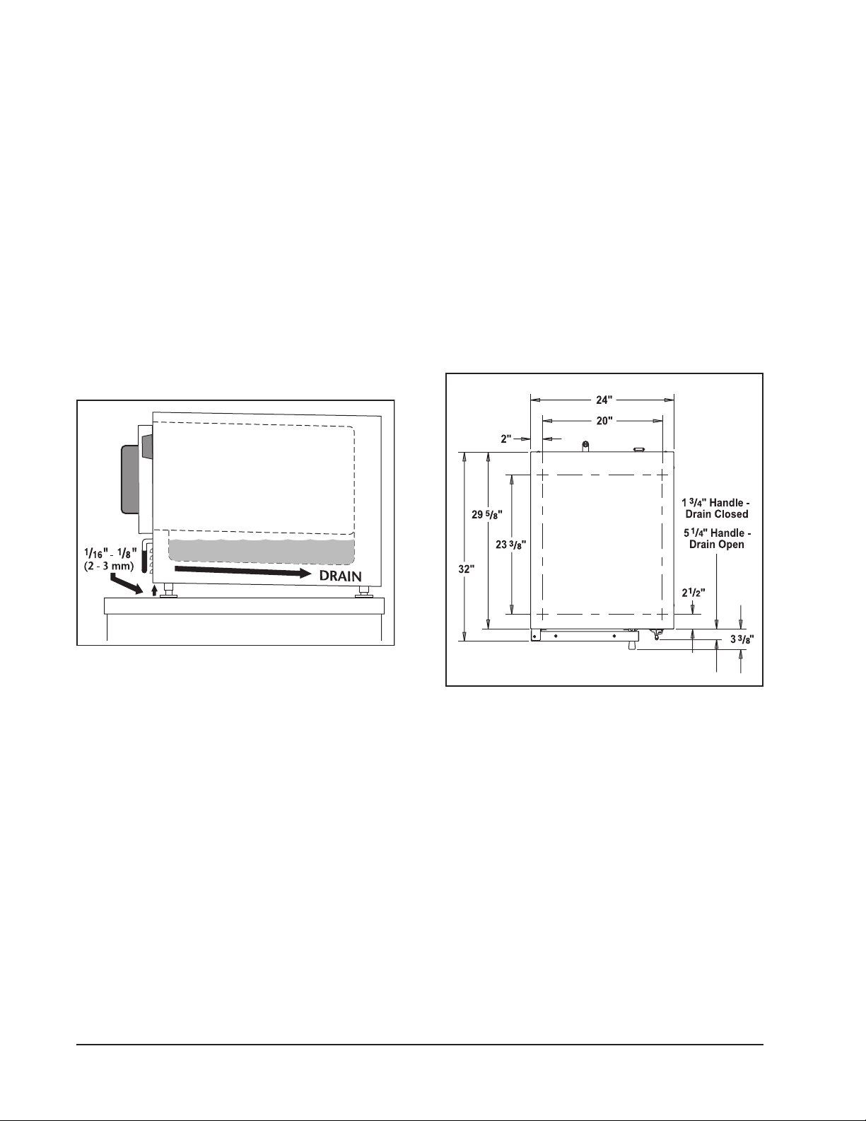
LEVELING
Position and level the unit using leveling feet.
Front of unit should be 1/16" to 1/8" higher than
the rear as indicated in Figure 1. Unit should
be level side to side.
Level the steamer front to back and side to side
by turning the adjustable feet.
ANCHORING STEAMER
1. Place steamer in the desired location on the
countertop and mark four corners. Remove
the steamer and drill 1/2" holes as indicated
in Figure 2.
2. Apply a bead of RTV or other NSF approved
sealant around the bottom edge of the
steamer. If anchoring the steamer, this
bottom seal is necessary to meet NSF
requirements.
3. Set steamer on countertop and bolt down
securely with 3/8" by 16" bolts (not supplied).
Screw length should be tabletop thickness
plus 1/2" for proper thread engagement.
Figure 1: Leveling Steamer
Figure 2: Anchoring Steamer
OPTIONAL ACCESSORIES
Optional accessories such as stands and stacking
kit will include directions for assembly.
— 6 —
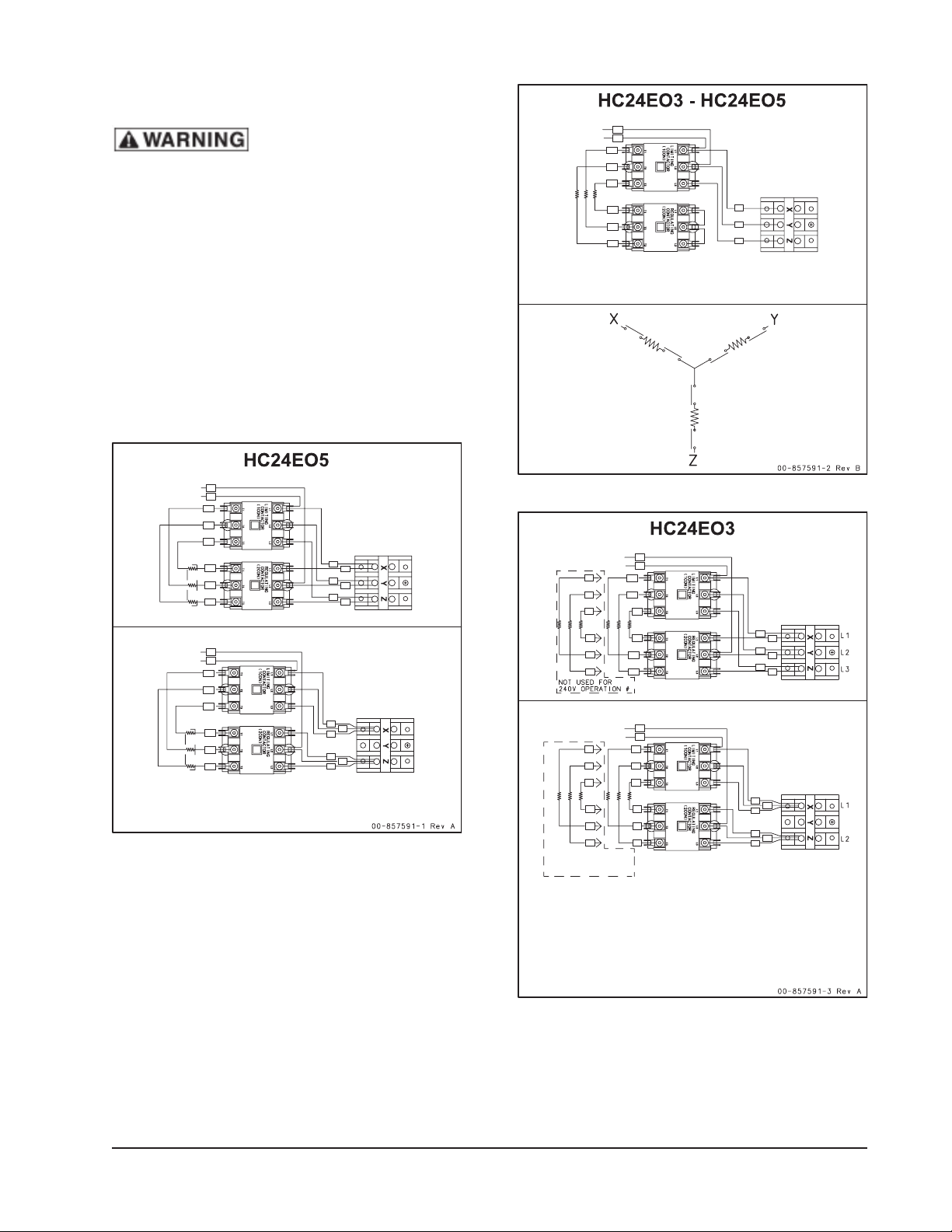
ELECTRICAL CONNECTIONS
To Control
Transformer *
To Control
Transformer *
3-PHASE, 208 V
3-PHASE, 240 V
1-PHASE, 208 V
1-PHASE, 240 V
B
BL
BR
YL
BL
BR
YL
21
24
21
22
23
24
25
26
22
25
23
26
BL
BR
YL
BL
BR
YL
A
B
A
*Primary taps of Control Transformer must be connected
according to the appliance data plate voltage marking and
actual connected supply.
To Control
Transformer *
3-PHASE, 380 V
3-PHASE, 415 V
3-PHASE, 480 V
B
BL
BR
YL
BL
BR
1CON L1 – T1
2CON T2 – L 2
1CON L2 – T2
2CON T3 –L3
2CON T1 –L1
1CON L3 - T 3
YL
21
22
23
A
*Primary taps of Control Transformer must be connected
according to the appliance data plate voltage marking and
actual connected supply.
To Control
Transformer *
To Control
Transformer *
3-PHASE, 208/240 V
1-PHASE, 208/240 V
B
BL
BR
YL
BL
BR
YL
21
24
21
22
23
24
25
26
22
25
23
26
BL
BR
YL
BL
BR
YL
GN
RD
OR
GN
RD
OR
GN
RD
OR
GN
RD
OR
A
B
A
*Primary taps of Control Transformer must be connected
according to the appliance data plate voltage marking and
actual connected supply.
** For operation from a 208 V supply, all 6 elements are to
be connected as shown. For 240 V supply, disconnect and
insulate element leads with Orange, Green and Red markers.
Not used for
240V operation **
: Electrical and grounding
connections must comply with the
applicable portions of the National
Electrical Code and/or other local
electrical codes.
When making electrical connections, use copper
wire suitable for at least 200°F (90°C). The
steamer must be grounded. The wiring diagram
is located on the inside of the right panel.
Steamers are wired for 3-phase and can be
converted to 1-phase by relocating the jumper
wires on the terminal block as shown on the
wiring diagram.
HC24EO SERIES STEAMER
— 7 —
HC24EO SERIES STEAMER
ELECTRICAL DATA
Model Volts KW Amp @ Amp @
1 PH 3 PH
HC24EO3 208 8 38.5 22.2
240 8 33.3 19.2
HC24EO5 208 12 57.7 33.3
240 12 50.0 28.9
480 12 N/A 14.4
SERVICE CONNECTIONS
Water Connections
No water supply connections are required, as
the steamer is lled manually.
Water Treatment
A local water treatment specialist should
be consulted before installation of steam
generating equipment.
life. Water conditions vary from one location
to another. Ask your municipal water supplier
for details about your local water supply prior
to installation. Presence of sediment, silica,
excess chlorides or other dissolved solids may
lead to a recommendation for alternate form(s)
of water treatment. Test the water with the test
strip included with the steamer. Other factors
affecting steam generation are iron content,
amount of chloridation and dissolved gases.
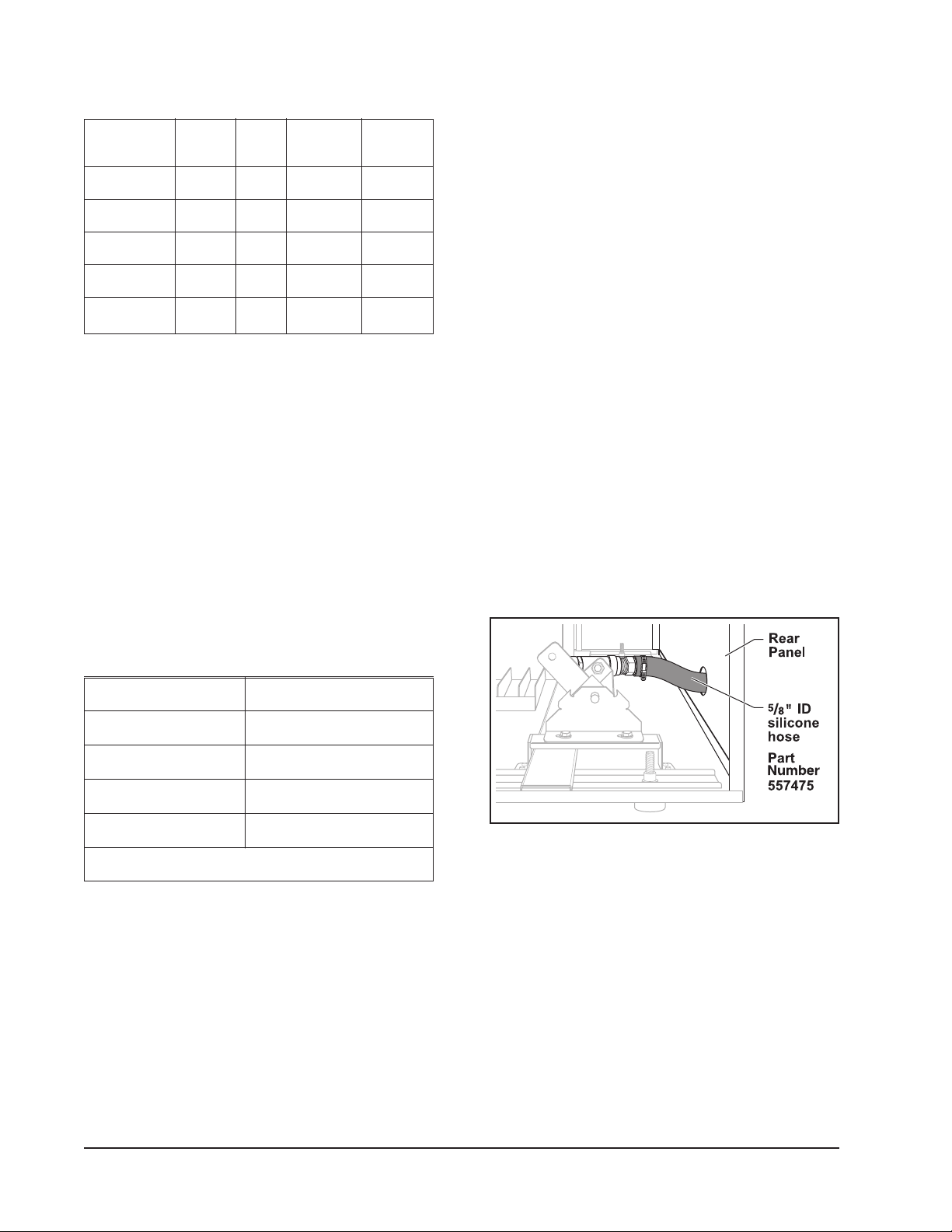
Drain Connection
The C24EO can be congured to drain through
either the rear panel or through the bottom
base plate.
The unit is congured to be drained through the
rear panel from the factory. The unit is supplied
with a 12" length of 5/8" ID hose. If this length is
insufcient, remove the hose and install a new
hose ordered to the desired length. The factory
5
/8" ID silicone hose part number is 557475.
Hose is sold by the foot.
See Figure 3.
Hardness* No more than 3 grains
Silica less than 13 ppm
Total Chlorine less than 4.0 ppm
PH range 6.5 to 8
Undissolved Solids less than 5 microns
*17.1 ppm = 1 grain of hardness
If the water supply fails to meet these standards,
it will be necessary to install a water conditioner.
The use of strainers or lters will not remove
minerals from the water.
Water Requirements
Proper water quality can improve the taste of
the food prepared in the steamer, reduce liming
in the steam generator and extend equipment
Figure 3: Rear Panel Drain Connection
(Viewed with right side panel removed)
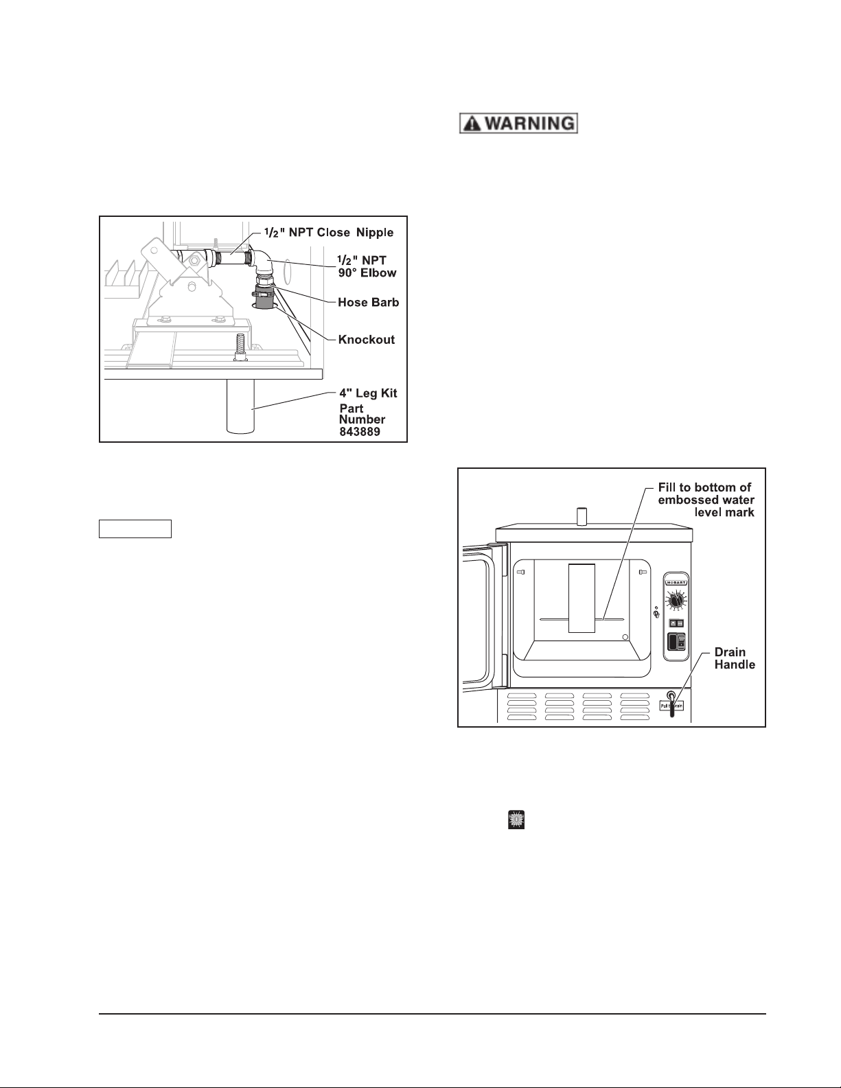
To eld congure the drain through the bottom
base plate, the 4" leg kit (part number 843889)
is required. Also required are a 1/2" NPT close
pipe nipple (11/8" long) and a 1/2" NPT 90°
elbow, which are available through local home
improvement or plumbing supply houses.
1. Remove right side panel.
2. Remove hose barb from drain.
3. Remove knockout from base plate.
— 8 —
HC24EO SERIES STEAMER
4. Install the 1/2" NPT close nipple (11/8" long)
into drain.
5. Install 1/2" NPT 90° elbow onto pipe nipple.
6. Re-use hose barb.
7. Install hose barb into elbow with clamp, cut
to desired length or route to drain.
Figure 4: Bottom Panel Drain Connection
(Viewed with right side panel removed)
INSTALLATION STARTUP PROCEDURE
: The steamer and its
parts are hot. Use care when operating,
cleaning or servicing the steamer. The
cooking compartment contains live steam
and hot water. Stay clear when opening
the door.
Once the steamer is installed, thoroughly test
the steamer before operation.
1. Check that the proper electrical connections
have been made.
2. Close the drain valve by pushing the Drain
Handle in, located in the lower right hand
corner. Open the door and pour water
into the cooking compartment up to the
water level mark (the water level mark is
visible on the back wall of the steamer).
Do not overfill.
NOTICE Do not connect steamer drain
solidly to any drain piping. The steamer drain
must vent to the atmosphere to avoid creating
a back pressure and possible back siphoning
into the compartment.
VENT HOOD
Local codes may require the steamer to be
located under an exhaust hood. Information
on the c onstructi on and insta llation of
ventilating hoods may be obtained from
Vapor Removal from Cooking Equipment,
NFPA Standard No. 96 (latest edition).
BEFORE FIRST USE
Thoroughly clean the steamer before using
for the rst time. See the CLEANING section
in this manual.
Figure 5: Water Level Mark
3. Rotate the Timer to CONTINUOUS position.
Fully depress the Power Switch to the
ON
position. The Power Switch will turn
amber, indicating the unit is turned on.
4. With the door open, press in on the door
switch (small rod), located above the
door latch. The COOK light will come on.
Release the door switch and the COOK
light will turn off.
— 9 —
HC24EO SERIES STEAMER
5. Close the compartment door and wait
approximately 10 minutes for unit to
preheat.
6. Rotate the Timer to 5 minutes. The Timer
will not start counting down until the cavity
has reached preheat temperature.
7. When the timer returns to 0, a buzzer will
sound signaling the end of the cooking
cycle. To silence the buzzer, turn the Timer
dial to the OFF position.
8. To turn the steamer off:
a. De pr es s th e Pow er Swi tc h to
the OFF
position.
b. Allow the steamer to cool.
c. Open the drain valve and drain the water
from the steamer.
d. Open the compartment door to allow
the inside to dry out.
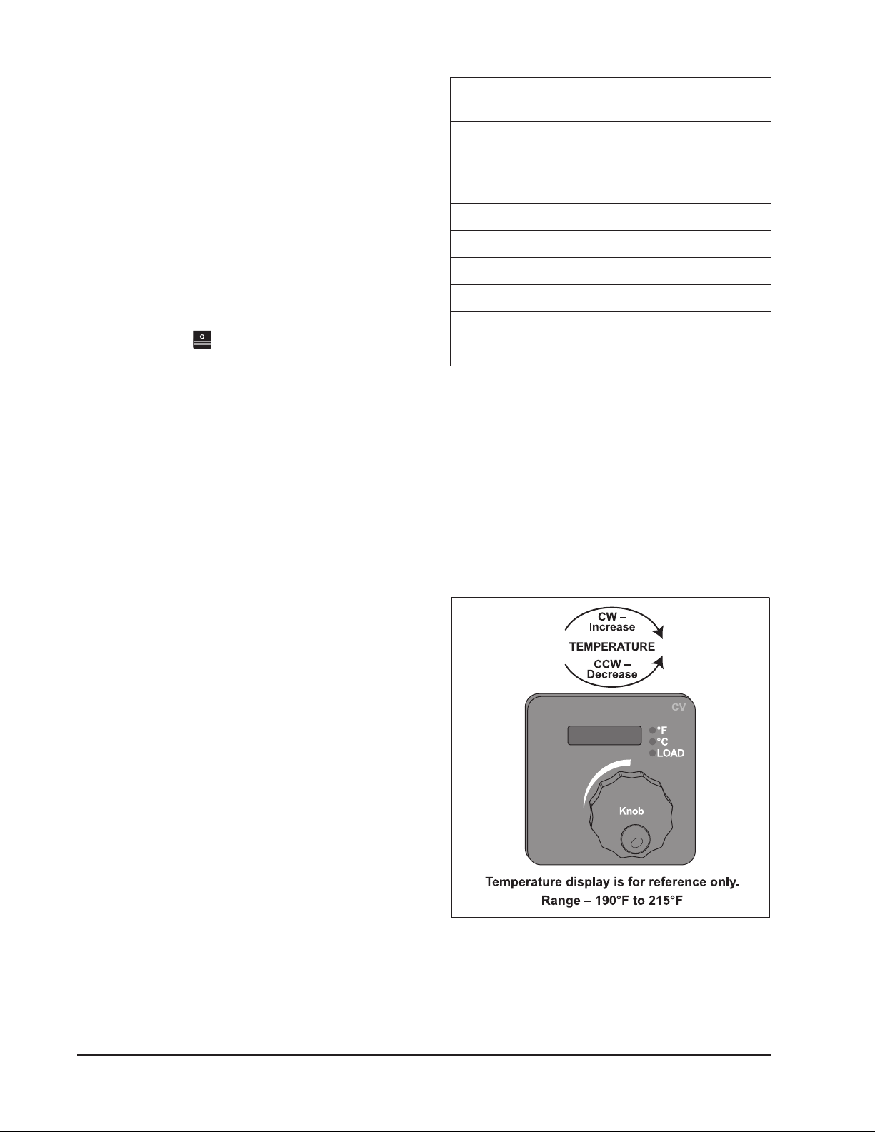
CALIBRATION PROCEDURE
ELEVATION DIGITAL
(FT) THERMOMETER - °F (C)
Sea Level 210 (99)
1,000 208 (98)
2,000 206 (97)
3,000 204 (96)
4,000 202 (94)
6,000 198 (93)
7,000 196 (91)
8,000 195 (90)
9,000 or above 194 (90)
1. Remove right side panel.
2. Place a temperature probe approximately
one inch down in the center of steam vent
pipe.
3. Turn steamer on by selecting CONTINUOUS
mode.
The right hand side panel must be removed
to access the temperature controller. To
achieve optimum steamer operation, rotate
the Temperature Control to the temperature
that corresponds to the elevation that it is
located at.
NOTE: The steamer is preset at the factory to
sea level.
A ha nd he l d d ig i ta l t he r mo m et er an d
thermocouple are required.
NOTE: If temperature setting is too high, the
boiling action will be excessive and cause
water droplets to exit the steam vent pipe
resulting in high water usage.
4. Using the table above, nd the corresponding
temperature for the elevation and set the
Temperature Control.
Figure 6: Temperature Control
— 10 —

HC24EO SERIES STEAMER
NOTE: Temperature Control is configured
by vendor to Fahrenheit and cannot
be changed to Celsius. The display
indicates set point temperature only.
a. Wait 3 seconds after releasing the
knob for the selection to be saved in
memory. Display will blink momentarily
to indicate temperature is saved.
b. Allow temperature to stabilize by
completing two heating cycles with
door closed.
NOTE: Temperature display on control is for
reference only. When calibrating, use
the recorded temperature from meter.
5. Record temperature reading from meter
when load light goes out.
6. Compare recorded temperature to the
temperature from table.
a. If recorded temperature is correct, no
adjustment is necessary.
b. If recorded temperature is not correct,
adjust temperature setting and re-check
the temperature reading with meter.
NOTE: If unit cannot be calibrated call your
Authorized Vulcan Servicer.
7. If correct temperature reading is not attained
after 3 attempts, call your Authorized Vulcan
Servicer.
— 11 —
HC24EO SERIES STEAMER
OPERATION
CONTROLS
: The steamer and its
parts are hot. Use care when operating,
cleaning or servicing the steamer. The
cooking compartment contains live steam
and hot water. Stay clear when opening
the door.
OPERATING THE STEAMER
1. Push the the drain lever in to close the drain
valve.
2. Open the door and pour water into the
cooking compartment up to the water level
mark. The water level mark is visible on the
back wall of the steamer. Unit capacity is 3
gallons. Do not overll.
3. Close door.
4. Verify Timer is in the OFF position.
5. Fully depress Power Switch to ON
position. Power light in switch will illuminate
amber.
6. Set timer to 5 minutes. In approximately 15
minutes unit will be preheated and ready to
cook.
7. Set timer to desired time (0 to 60 minutes)
or to CONTINUOUS position.
8. At the end of the timed cycle an audible
alarm will sound.
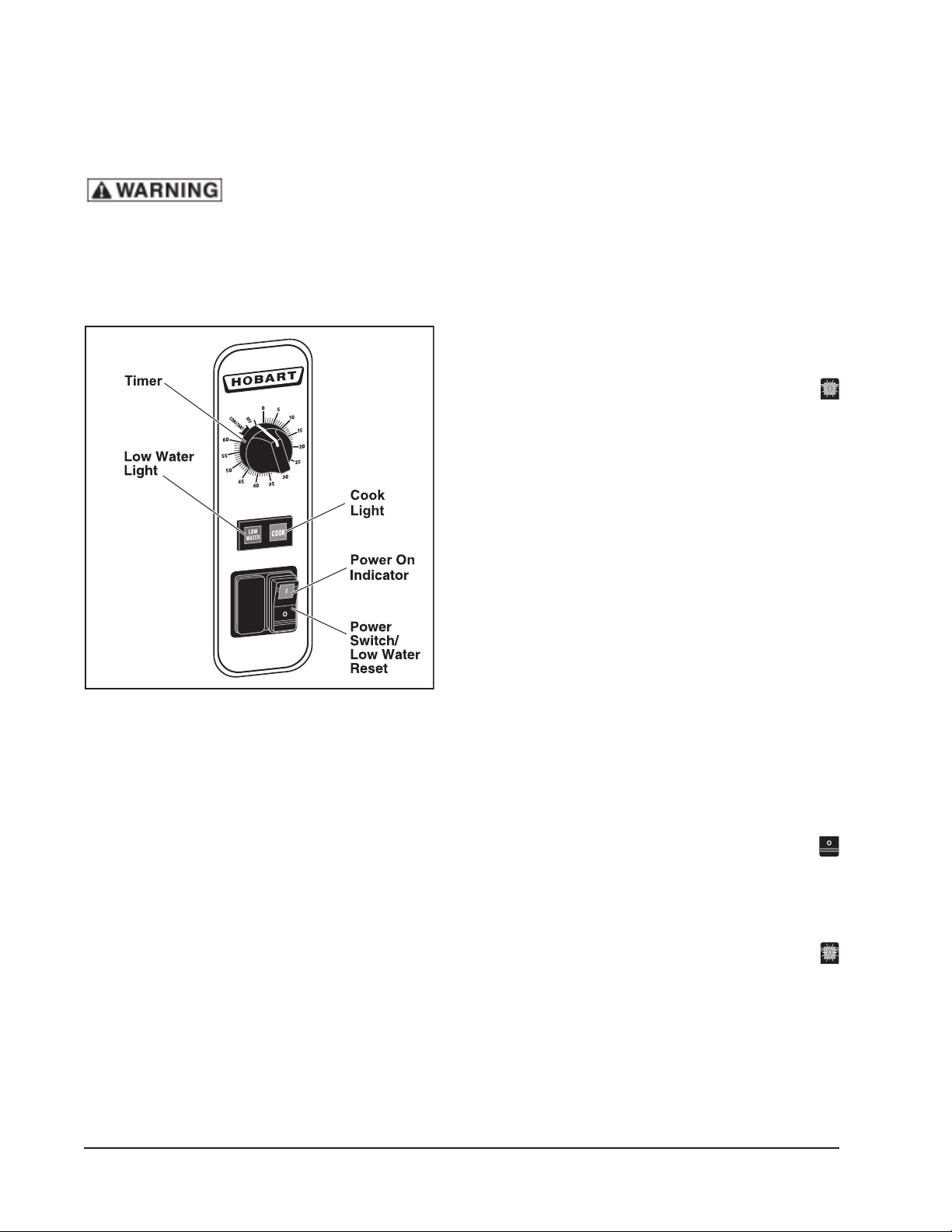
Figure 7: Controls
Power Switch/Low Water Reset: Turns
unit OFF/ON/RESETS LOW WATER LIGHT/
ALARM.
Low Water Light: When lit, indicates additional
water is required.
Timer: Selects the desired cooking time or
the CONTINUOUS position.
COOK Light: When lit, indicates the timer is
set and door is closed.
9. The unit returns to the idle temperature.
NOTE: Timer will not function until preheat has
been completed.
LOW WATER
1. When the Low Water light is illuminated
the unit needs to be relled with water. An
audible alarm will sound.
2. Fully depress Power Switch to OFF
position.
4. Rell unit with water.
5. Close door.
6. Fully depress Power Switch to ON
position to cancel Low Water alarm.
7. Timer will resume when steamer reaches
cooking temperature.
NOTE: Rell the unit when not in use or during
slow times to avoid running out of water.
Running out of water during a cooking
cycle will lengthen cook time.
— 12 —

HC24EO SERIES STEAMER
SHUTDOWN
1. Rotate Timer to OFF position.
2. Fully depress Power Switch to OFF
position.
3. Allow steamer to cool.
4. Open the drain valve and drain the water
from steamer.
5. Open the compartment door to allow the
inside to dry.
6. Follow cleaning instructions in this
manual.
EXTENDED SHUTDOWN
1. Fully depress Power Switch to OFF
position.
2. Clean the interior and exterior of unit.
3. Leave door open.
4. Disconnect power.
— 13 —
HC24EO SERIES STEAMER
CLEANING
COOKING COMPARTMENT DRAIN
Remove any particles or debris that may be
blocking the drain. Make a solution of warm
water with non-chloride detergent and pour
1
/2 gallon (1.9 liters) of it down the compartment
drain. Rinse by pouring 1/2 gallon (1.9 liters) of
hot water down the compartment drain.
Thoroughly clean the exposed surfaces
(sides, front, door and top) with a damp cloth
and polish with a clean cloth daily. To remove
discolorations, use a nonabrasive cleaner.
DOOR GASKET
Clean the gasket sealing surface of the
compartment door daily to remove food acids for
maximum gasket life. Do not use any solvents or
sharp instruments. Wash with a cloth moistened
in a solution of mild detergent and warm water.
Rinse with a fresh cloth moistened with warm
water to remove all traces of detergent.
Wipe dry with a clean cloth. Never apply food
oils or petroleum lubricants directly to the
door gasket. Petroleum-based solvents and
lubricants will reduce gasket life.
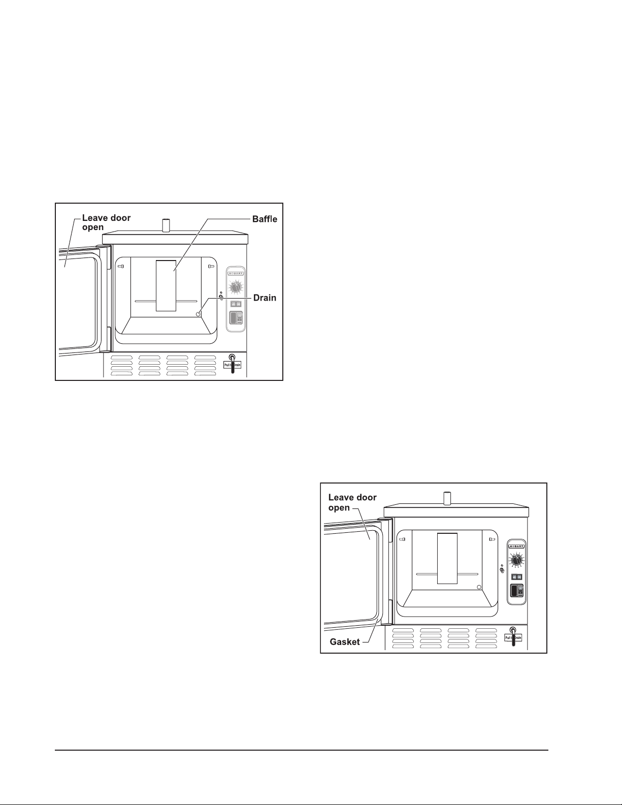
LEAVE COMPARTMENT DOOR OPEN
Figure 8: Oven Cavity
COMPARTMENT
The compartment, pan guides, and bafe
should be cleaned daily. The exterior should
be cleaned daily.
Remove the pan guides by lifting up and out.
Wash with a solution of warm water with nonchloride detergent. Rinse with warm water.
Remove the bafe from the compartment by
lifting up and out. Wash with a solution of warm
water with non-chloride detergent. Rinse with
warm water.
NOTE: Failure to reinstall bafe after cleaning
will affect cooking performance.
Wash the inside of the compartment with
a solution of warm water with non-chloride
detergent. Rinse with warm water.
Leave the compartment door slightly open
when the steamer is not in use. When the
compartment is idle, never latch the door and
apply pressure to the door gasket. Leaving the
gasket under pressure can cause permanent
deformation and reduce gasket life.
Figure 9: Leave Door Open
— 14 —

HC24EO SERIES STEAMER
STAINLESS STEEL EQUIPMENT CARE
AND CLEANING
Contrary to popular belief, stainless steels
ARE susceptible to rusting.
Corrosion on metals is everywhere. It is
recognized quickly on iron and steel as unsightly
yellow/orange rust. Such metals are called
“active” because they actively corrode in a
natural environment when their atoms combine
with oxygen to form rust.
Stainless steels are passive metals because
they contain other metals, like chromium, nickel
and manganese, that stabilize the atoms.
400 series stainless steels are called ferritic,
contain chromium, and are magnetic; 300 series
stainless steels are called austenitic, containing
chromium and nickel; and 200 series stainless,
also austenitic, contains manganese, nitrogen
and carbon. Austenitic types of stainless are
not magnetic, and generally provide greater
resistance to corrosion than ferritic types.
With 12 to 30% chromium, an invisible passive
lm covers the steel’s surface acting as a shield
against corrosion. As long as the lm is intact
and not broken or contaminated, the metal is
passive and stainless. If the passive lm of
stainless steel has been broken, equipment
starts to corrode and starts to rust.
Enemies of Stainless Steel
There are three basic things which can break
down stainless steel’s passivity layer and allow
corrosion to occur.
1. Mechanical abrasion.
Water comes out of the faucet in varying degrees
of hardness. Depending on what part of the
country you live in, you may have hard or soft
water. Hard water may leave spots, and when
heated leaves deposits behind that if left to sit, will
break down the passive layer and rust stainless
steel. Other deposits from food preparation and
service must be properly removed.
Chlorides are found nearly everywhere. They
are in water, food and table salt. One of the
worst chloride perpetrators can come from
household and industrial cleaners.
So what does all this mean?
Don’t despair!
Here are a few steps that can help prevent
stainless steel rust.
1. Use the proper tools.
When cleaning stainless steel products,
use non-abrasive tools. Soft cloths and
plastic scouring pads will not harm steel’s
passive layer. Stainless steel pads also
can be used but the scrubbing motion must
be in the direction of the manufacturers’
polishing marks.
2. Clean with the polish lines.
Some stainless steel comes with visible
polishing lines or grain. When visible lines
are present, always scrub in a motion
parallel to the lines. When the grain cannot
be seen, play it safe and use a soft cloth or
plastic scouring pad.
3. Use alkaline, alkaline chlorinated or nonchloride containing cleaners.
2. Deposits and water.
3. Chlorides.
Mechanical abrasion means those things that
will scratch a steel surface. Steel pads, wire
brushes and scrapers are prime examples.
While many traditional cleaners are loaded
with chlorides, the industry is providing
an ever-increasing choice of non-chloride
cleaners. If you are not sure of chloride
content in the cleaner used, contact your
cleaning supplier. If your present cleaner
contains chlorides, ask your supplier if
they have an alternative. Avoid cleaners
containing quaternary salts; it also can
attack stainless steel and cause pitting
and rusting.
— 15 —

HC24EO SERIES STEAMER
4. Treat your water.
Though this is not always practical,
softening hard water can do much to reduce
deposits. There are certain lters that can be
installed to remove distasteful and corrosive
elements. To insure proper water treatment,
call a treatment specialist.
5. Keep your food equipment clean.
Use alkaline, alkaline chlorinated or non-
chloride cleaners at recommended strength.
Clean frequently to avoid build-up of hard
stubborn stains. If you boil water in stainless
steel equipment, remember the single
most likely cause of damage is chlorides
in the water. Heating cleaners that contain
chlorides have a similar effect.
6. Rinse, rinse, rinse.
If chlorinated cleaners are used, rinse
and wipe equipment and supplies dry
immediately. The sooner you wipe off
standing water, especially when it contains
cleaning agents, the better. After wiping
equipment down, allow it to air dry; oxygen
helps maintain the stainless steel’s passivity
lm.
7. Never use hydrochloric acid (muriatic
acid) on stainless steel.
8. Regularly restore/passivate stainless
steel.
Recommended cleaners for specic
situations
Cleaning
Job
Routine
cleaning
Fingerprints
& smears
Stubborn
stains &
discoloration
Grease &
fatty acids,
blood, burnton-foods
Grease & oil
Restoration/
Passivation
Agent
Soap,
ammonia,
detergent,
Medallion
Arcal 20, LacO-Nu Ecoshine
Cameo, Talc,
Zud, First
Impression
Easy-off, DeGrease It Oven
Aid
Any good
commercial
detergent
Benet, Super
Sheen
Comments
Apply with cloth
or sponge
Provides barrier
lm
Rub in direction
of polish lines
Excellent
removal on all
nishes
Apply with
sponge or cloth
Review
1. Stainless steels rust when passivity (lm-shield) breaks down as a result of scrapes, scratches,
deposits and chlorides.
2 Stainless steel rust starts with pits and cracks.
3. Use the proper tools. Do not use steel pads, wire brushes or scrapers to clean stainless steel.
4. Use non-chlorinated cleaners at recommended concentrations. Use only chloride-free
cleaners.
5. Soften your water. Use lters and softeners whenever possible.
6. Wipe off cleaning agent(s) and standing water as soon as possible. Prolonged contact causes
eventual problems.
To learn more about chloride-stress corrosion and how to prevent it, contact the equipment
manufacturer or cleaning material supplier.
— 16 —

HC24EO SERIES STEAMER
Developed by Packer Engineering, Naperville, Ill., an independent testing laboratory.
MAINTENANCE
: The steamer and its
parts are hot. Use care when operating,
cleaning or servicing the steamer. The
cooking compartment contains live steam
and hot water. Stay clear when opening
the door.
Steamer must be cleaned daily. See CLEANING
section.
REMOVAL OF LIME SCALE DEPOSITS
: Read and follow the
instructions on the deliming material
package. Avoid contact with skin and eyes.
Wear plastic or rubber gloves and safety
goggles when handling. Wash thoroughly
after handling. If deliming solution comes
in contact with the skin or eyes, rinse
thoroughly with clean water.
: The steamer and its
parts are hot. Use care when operating,
cleaning or servicing the steamer. The
cooking compartment contains live steam
and hot water. Stay clear when opening
the door.
The steamer should be delimed when scale
is present in the cavity well. Deliming may be
required frequently depending on water quality
and scale build up. This is in accordance with
the minimum preventive maintenance schedule
required by warranty.
2. Plastic or rubber gloves.
3. Safety goggles or face shield.
4. Spray bottle.
5. 1-gallon container for mixing the deliming
solution.
NOTE: Deliming solution may cause the surface
of aluminum measuring tools to tarnish
or etch.
Procedure:
1. Turn steamer off. Drain the steamer.
2. One bag will treat a C24EO3 or C24EO5
steamer.
• 1 bag to 2 gallons warm water
3. Spray cavity walls with solution. Pour
solution into cavity well.
• Maximum steamer capacity 3 gallons
4. Fully depress Power Switch to ON
position and set Timer for 5 min. After timer
sounds, rotate Timer dial to OFF position
and fully depress Power Switch to OFF
position.
5. Let delime solution soak for a minimum of
30 minutes, maximum 60 minutes. If scale
is still present, repeat steps 1 through 5.
6. Drain the steamer and rinse thoroughly with
warm clean water.
7. Dry with a clean dry cloth.
8. Leave steamer door open when not in use.
DOOR GASKET
Items required (not provided):
1. Deliming Solution – Scale Release™
Part Number 854893-13 (qty. 1).
• Contact the local Authorized Vulcan
Servicer or refer to website
www.hobartcorp.com
If the door gasket is leaking due to a nick or
cut, it must be replaced. Damage to the gasket
sealing surface will cause steam leakage.
— 17 —

HC24EO SERIES STEAMER
COOKING HINTS
The steamer efficiently cooks vegetables and
other foods for immediate serving. Steam
cooking should be carefully time controlled.
Keep hot food holding-time to a minimum to
produce the most appetizing results. Prepare
small batches. Cook only enough to start
serving, then cook additional amounts to
meet demand.
ACCEPTABLE PAN SIZES
The steamer accommodates combinations
of full, half and one-third size pans, solid or
perforated.
Model Number of Pans Accommodated
Depth of Pan
1" 21/2" 4" 6"
C24EO3 6 3 2 1
PREPARATION
Prepare vegetables, fruits, meats, seafood and
poultry normally by cleaning, separating, cutting,
removing stems, etc. Cook root vegetables in
a perforated pan. Other vegetables may be
cooked in a perforated pan unless juices are
being saved. Liquids can be collected in a solid
12" x 20" pan placed under a perforated pan.
Perforated pans are used for frankfurters,
wieners and similar items when juices do not
need to be preserved. Solid pans are good
for cooking puddings, rice, and hot breakfast
cereals. Vegetables and fruits are cooked in
solid pans in their own juice. Meats and poultry
are cooked in solid pans to preserve their juice
or retain broth.
Canned foods can be heated in their opened
cans (cans placed in 12" x 20" solid pans) or
the contents may be poured into solid pans. DO
NOT place unopened cans in the steamer.
C24EO5 10 5 3 2
COOKING GUIDELINES
The steamer cooks vegetables, frankfurters,
eggs in their shells, and certain other meats
or food items at atmospheric pressure.
These cooking guidelines are suggestions only.
You should experiment with your food products
to determine the cooking times that will give you
the best results. Variables which affect cooking
time include size, weight, thickness of foods,
temperature, density, previous condition of
the foods (fresh, pre-blanched or frozen) and
degree of doneness desired.
Frozen Food Items
Separate frozen foods into smaller pieces to
allow more efcient cooking.
Use a pan cover for precooked frozen dishes
that cannot be cooked in the covered containers
in which they are packed if they require more
than 15 minutes of cooking time. When a cover
is used, approximately one-third additional
cooking time is necessary.
Cooking time for frozen foods depends on
the amount of defrosting required. If time
permits, allow frozen foods to partially thaw
overnight in a refrigerator. This will reduce
their cooking time.
— 18 —

HC24EO SERIES STEAMER
PRODUCTS TO BE COOKED IN SOLID PANS
PRODUCT TIME (MINUTES) WEIGHT PER PAN
Eggs, Scrambled 9 to 12 8 doz.
Rice, Long Grain (Cover with 4 cups water/lb.) 23 to 25 2 lbs.
Pasta (Place perforated pan inside solid pan,
cover with cold water)
Spaghetti Regular/Vermicelli 10 to 15
Macaroni - Shells/Elbows 13 to 18
Noodles - 1/2" Wide 10 to 15
Lasagna Noodles 13 to 18
Frozen Casseroles, Lasagna 33 to 35 Full Pan
Meat Loaf, 3-5 Lb. Each 38 to 40 15 lbs.
Beef
Ground Chuck 19 to 25 10 lbs.
Sliced as Purchased 33 to 40 10 lbs.
Shrimp, Frozen, 10 Shrimp per Lb. 4 to 5 4 lbs.
Beans
Baked 8 to 9 10 lb. Can
Refried 8 to 9 10 lb. Can
Canned Vegetables 5 to 6 10 lb. Can
Prunes, Dried 11 to 15
— 19 —

HC24EO SERIES STEAMER
PRODUCTS TO BE COOKED IN PERFORATED PANS
PRODUCT TIME (MINUTES) WEIGHT PER PAN
SEAFOOD
Clams
Frozen 9 to 12 3 doz.
Fresh, Cherrystone 4 to 6 3 doz.
King Crab, Frozen
Claws 3 to 4 21/2 lbs.
Legs 3 to 6 41/2 lbs.
Lobster Tail, Frozen 5 to 6 10 lbs.
Lobster, Live, 10" - 12" 4 to 5 4 Per Pan
Salmon Fillets, Frozen, 8 ounce each 4 to 5 71/2 lbs.
Scallops, Fresh 3 to 4 3 lbs.
Scrod Fillets, Fresh 3 to 5 4 lbs.
EGGS
Hard Cooked 14 to 15 4 doz.
Soft Cooked 8 to 10 4 doz.
Soft Yoke for Caesar Salad 5 to 8 4 doz.
MEATS
Chicken — Breasts, Legs, Thighs 19 to 20 15 lbs.
Turkey, Frozen
Breasts (2) 86 to 90 6 to 7 lbs. Each
Cut Lengthwise 53 to 55 20 to 25 lbs.
Corned Beef 40 to 75 6 to 8 lbs.
Hot Dogs and Wieners 2 to 3 80 to 100 Count
VEGETABLES
Asparagus Spears
Frozen 10 to 12 3 lbs.
Fresh 4 to 5 5 lbs.
Beans
Green 2" Cut, Frozen/Fresh 5 to 6 5 lbs.
Lima, Frozen 7 to 8 5 lbs.
Baby Lima, Frozen 4 to 5 5 lbs.
Brussel Sprouts, Frozen 5 to 6 5 lbs.
— 20 —

HC24EO SERIES STEAMER
PRODUCT TIME (MINUTES) WEIGHT PER PAN
VEGETABLES (Cont’d.)
Broccoli
Spears, Frozen 6 to 8 4 lbs.
Spears, Fresh 4 to 6 5 lbs.
Flowerettes, Frozen 4 to 6 5 lbs.
Cabbage, Fresh, 1/6 Cut 6 to 8 5 lbs.
Carrots
Baby Whole, Frozen 6 to 8 7 lbs.
Crinkle Cut, Frozen 7 to 8 4 lbs.
Sliced, Fresh 9 to 11 9 lbs.
Cauliower, Flowerettes
Frozen 4 to 6 4 lbs.
Fresh 7 to 8 5 lbs.
Celery, 1" Diagonal Cut 5 to 7 5 lbs.
Corn
Yellow Whole Kernel, Frozen 3 to 5 5 lbs.
Cobbettes, Frozen 6 to 8 27 Ears
Corn-On-Cob, Fresh 16 to 18 80 Ears
16 to 18 54 Ears
10 to 12 18 Ears
Peas, Green 4 to 6 5 lbs.
Potatoes, Whole Russet 50 to 55 40 lbs.
Spinach
Chopped, Frozen 15 to 17 6 lbs.
Defrosted 4 to 5 6 lbs.
Fresh Cut 2 to 3 2 lbs.
Squash, Acorn Halves 22 to 25 10 Halves
Zucchini, Slices 6 to 8 10 lbs.
Frozen Mixed Vegetables 6 to 7 5 lbs.
FRUIT
Fruit, Blanch for Peeling
Grapefruit, Oranges 2 to 3
Pineapple, Whole for Cutting 2 to 4
— 21 —

HC24EO SERIES STEAMER
TROUBLESHOOTING
SYMPTOMS
Steamer not steaming
Steamer not
steaming properly
Door leaks
Water does not drain
properly
Water foaming
POSSIBLE CAUSES
No main power source.
Door is open.
Power switch in OFF position.
Timer is off.
Needs water.
Excessive scale buildup in the
cavity well.
Not connected to correct voltage.
Damaged door gasket.
Damage to gasket sealing surface.
Blocked or obstructed steam vent.
Unit not level.
Drain clogged.
Cooking seafood without catch
pan.
REMEDY
Check the power source.
Close door.
Set power switch to ON.
Set Timer.
Add water.
Descale the steamer (see
REMOVAL OF LIME SCALE
DEPOSITS).
If voltage is not correct, contact
your Authorized Vulcan Servicer.
Check door gasket for damage.
If adjustment is needed, contact
your Authorized Vulcan Servicer.
Clear steam vent.
See leveling instructions in
the installation section of this
manual.
Unclog drain.
Use a catch pan. Drain and
replace water.
— 22 —

HC24EO SERIES STEAMER
SERVICE AND PARTS INFORMATION
To obtain service and parts information concerning this model, contact the Authorized Vulcan Servicer
in your area. Refer to our website, www.hobartcorp.com for a complete listing of Authorized Service
and Parts depots.
When calling for service, the following information (located on your machine data plate) must be
available:
Model Number
Serial Number
Manufacture Date (MD)
Voltage
— 23 —

HC24EO SERIES STEAMER
(05-10)
— 24 —
PRINTED IN U.S.A.
 Loading...