

Page 1
FRYER FILTER-IN-A-DRAWER
SUPPLEMENT TO INSTRUCTION MANUALS FOR:
Gas Fryer Models* Electric Fryer Models**
ML-135536 HG35F ML-126964 HFD40F
ML-135537 HG45F ML-126966 HFD50F
ML-135538 HG65F ML-126970 HFD85F
ML-135539 HG85F
ML-126965 HFC40F
ML-126953 HGD35F ML-126967 HFC50F
ML-126956 HGD45F ML-126971 HFC85F
ML-126959 HGD65F
ML-126962 HGD85F ML-126968 HD225F
ML-126954 HGC35F ML-126969 HC225F
ML-126957 HGC45F
ML-126960 HGC65F
ML-126963 HGC85F
* F-34085 and F-34086 Rev. A
** F-33637 Rev. B
701 S. RIDGE AVENUE
TROY, OHIO 45374-0001
937 332-3000
www.hobartcorp.com
FORM 34727 Rev. B (Jan. 2003)
Page 2

Table of Contents
GENERAL .............................................................................................................................................3
ASSEMBLY .....................................................................................................................................3
CONTROLS AND COMPONENT LOCATIONS — GAS FRYERS .................................................4
CONTROLS AND COMPONENT LOCATIONS — ELECTRIC FRYERS.......................................5
OPERATION.........................................................................................................................................6
FILTERING PROCEDURE WHEN USING LIQUID SHORTENING .........................................6
FILTERING PROCEDURE WHEN USING SOLID SHORTENING ...........................................7
FILTERING TIPS ............................................................................................................................8
PERIODICALLY REMOVE EXCESS DEBRIS FROM THE FILTER .........................................8
FLUSH AND DISCARD ................................................................................................................. 8
MAINTENANCE................................................................................................................................. 10
CLEANING THE FILTER DRAWER .......................................................................................... 10
FRYER BOIL-OUT INSTRUCTIONS......................................................................................... 11
TROUBLESHOOTING ...................................................................................................................... 12
SERVICE...................................................................................................................................... 12
© HOBART CORPORATION, 2003
–2 –
Page 3

OPERATION AND CARE OF
FRYER FILTER-IN-A-DRAWER
SAVE THESE INSTRUCTIONS
GENERAL
The Fryer Filter-In-A-Drawer filters the oil as it is pumped back to its respective tank. Valves inside the
doors under each fry tank must be set so only one tank is being drained, filtered and pumped back at
any one time.
The Fryer Filter-In-A-Drawer is used on the following Hobart Fryer Models:
Gas Fryers Electric Fryers
HG35F HGD35F HGC35F HFD40F HFC40F
HG45F HGD45F HGC45F HFD50F HFC50F
HG65F HGD65F HGC65F HFD85F HFC85F
HG85F HGD85F HGC85F HD225F HC225F
ASSEMBLY
1. After unpacking, wash the filter tank, crumb basket and filter screen. Use dishwashing
detergent and warm water, or clean the components in a dishwasher. Rinse the filter tank,
crumb basket and filter screen thoroughly. Wipe components dry with a clean cloth.
2. Pull the filter drawer out.
3. Place the filter tank in the filter drawer. Hang the crumb basket from the left tank handle inside
the filter tank (Figs. 1 and 2). Position the filter screen assembly flat on the bottom of the filter
tank so the filter orifice underneath the screen fits the suction hole in the bottom of the tank (Figs.
1 and 2). Close the drawer.
4. Make sure the two O-Rings are in place inside the filter suction port (Figs. 1 and 2). As the
drawer is closed, make sure the filter suction connector fits tightly into the filter suction port
(Figs. 1 and 2).
–3 –
Page 4
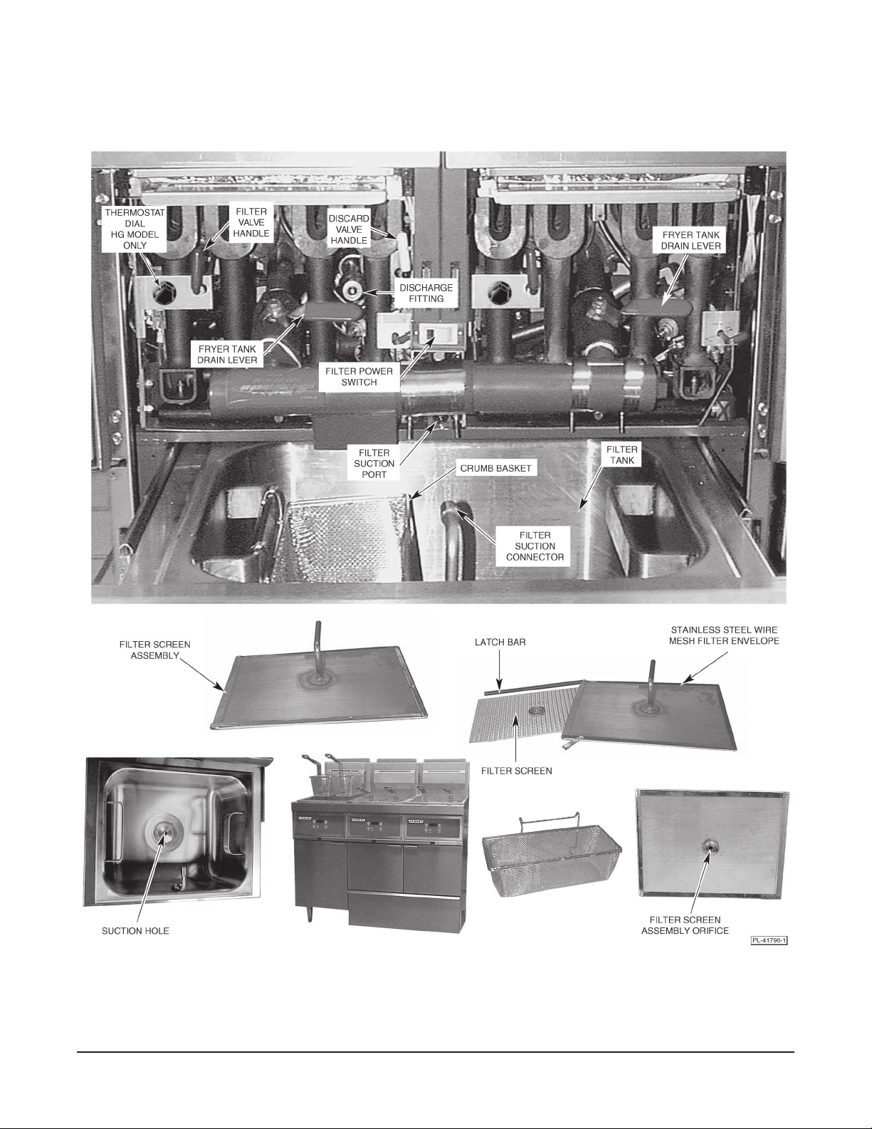
CONTROLS AND COMPONENT LOCATIONS — Gas Fryers
The filter tank cover is removed to show component locations.
Fig. 1
–4 –
Page 5

CONTROLS AND COMPONENT LOCATIONS — Electric Fryers
The filter tank cover is removed to show component locations.
Fig. 2
–5 –
Page 6

OPERATION
WARNING: HOT FRYING COMPOUND AND PARTS CAN CAUSE BURNS. USE CARE WHEN
OPERATING, CLEANING OR SERVICING THE FRYER. USE CARE WHEN FILTERING. DO NOT
LEAVE UNATTENDED.
WARNING: SPILLING HOT FRYING COMPOUND CAN CAUSE SEVERE BURNS. DO NOT
MOVE THE FRYER WITHOUT DRAINING ALL FRYING COMPOUND FROM THE TANK.
FILTERING PROCEDURE WHEN USING LIQUID SHORTENING
1. Turn the fryer's power OFF and open the doors (Fig. 3).
NOTE: HGC and HGD models have a drain valve interlock
system built in that will automatically shut the fryer off as soon
as the drain valve is opened.
2. Slowly turn the red fryer tank drain lever counterclockwise
(Fig. 5) until it stops. This allows the oil to drain into the filter
tank.
NOTE: Drain and filter only one fryer tank at a time.
Fig. 3
3. Pull the filter drawer out. Lift the filter tank cover up (Fig. 4). Make sure filter tank and parts are
properly assembled (pages 3 through 5).
4. Add 8 ounces of diatomaceous earth to the filter tank. Agitate to mix the diatomaceous earth
and shortening. Replace the filter tank cover. Slide the filter drawer back into place.
PL-41601
Fig. 4 Fig. 5
PL-41602
5. Turn the filter power switch ON (Fig. 6). The red pilot light in the filter power switch comes on.
PL-41603
Gas Fryer Electric Fryer
Fig. 6
–6 –
PL-41604
Page 7

6. To start filtering, pull out the red filter valve handle (Fig. 7) of the fryer tank to be filtered. Use
PL-41607
a brush to remove all the residue from the bottom of the tank into the drain tube. Let the oil recycle
for 1 to 3 minutes, flushing residue from the tank bottom into the filter.
PL-41605
Gas Fryer Electric Fryer
Fig. 7
7. Close the red fryer tank drain lever (Fig. 8) by turning
the lever clockwise until it stops. The fryer tank will now
refill.
8. After filtering is complete (all oil is removed from the
filter tank and air bubbles should appear in the fryer
tank), push in the red filter valve handle completely
(Fig. 9).
PL-41606
Fig. 8
PL-41608
Gas Fryer Electric Fryer
Fig. 9
9. Turn the filter power switch OFF (Fig. 6).
10. Close the fryer doors.
FILTERING PROCEDURE WHEN USING SOLID SHORTENING
1. Follow the fat melt procedure discussed in the
INSTRUCTION
2. Set the fryer thermostat at 350°F (177°C).
–7 –
PL-41609
manual supplied with your fryer.
Page 8

PL-41612
3. Once shortening has melted, stir oil to eliminate
COLD ZONE
- MIN -
- MAX -
COLD ZONE
PL-56013
- MIN -
- MAX -
solid shortening in the cold zone (Fig. 10). All
solid shortening must have melted completely.
4. Allow the fryer to idle at 350°F (177°C) for
10 minutes, if filtering from a cold start.
5. Turn the fryer off. Make sure filter tank and
parts are properly assembled (pages 3
through 5). Make sure the filter drawer is
completely closed before opening the drain
valve. Open the drain valve and drain the
shortening into the filter tank. Allow hot
Fig. 10
shortening to stand in the filter tank for
approximately 6 to 10 minutes. Then proceed
with steps 4 through 10 under Filtering
Procedure when Using Liquid Shortening on
pages 6 and 7.
FILTERING TIPS
• If filtering at the end of the day, make sure all the oil is returned to the fryer tank.
• Open the filter drawer approximately 1" to allow any oil in the return line to run back into the filter
tank. This will take about 30 seconds to complete.
• Close the filter drawer. If solid shortening is used, follow the "Melt" procedure the next morning.
PERIODICALLY REMOVE EXCESS DEBRIS FROM THE FILTER
The following operation is required after filtering one or more batches, as needed:
1. Pull the filter drawer out and remove the filter tank cover from the filter tank.
2. Remove the crumb basket and empty any debris into the trash.
3. Remove the filter screen assembly.
4. Scrape debris from the bottom of the filter tank and from the screen assembly into the trash.
NOTE: Scrape debris away from suction hole to avoid compacting debris in hole.
5. Reinstall the filter screen assembly and crumb basket.
6. Replace the filter tank cover. Close the drawer.
FLUSH AND DISCARD
1. Turn the fryer power OFF.
2. Make sure filter tank and parts are properly assembled
(pages 3 through 5). Open the fryer tank drain lever (Fig.
11) of the fryer tank that holds oil that is to be discarded.
Fig. 11
–8 –
Page 9

3. While holding the discard hose at the base of the fitting, use your free hand to slide the collar
away from the end of the female fitting (Fig. 12). Align the male and female parts of the quick
disconnect line and push the hose onto the male connector discharge fitting. Release the collar.
Pull the discharge hose away from the fryer to make sure discharge hose is fully inserted and
locked.
PL-41613
Gas Fryer Electric Fryer
Fig. 12
PL-41614
4. Turn the filter power switch ON (Fig. 13).
PL-41615
Gas Fryer Electric Fryer
Fig. 13
PL-41616
5. Place the nozzle in a suitable discharge container. To start the pump, pull the white discard
valve handle out (Fig. 14); the oil begins to flow through the discard hose. If the discharge
container is not large enough for the entire amount, stop the pump by pushing in the white
discard valve handle, empty the container and resume. When the last of the oil is in the
discharge container, stop the pump by pushing in the white discard valve handle, turn the filter
power switch OFF and disconnect the discharge hose (Fig. 15).
6. Clean the filter drawer following the instructions on page 10.
PL-41617
Fig. 14
–9 –
PL-41618
Fig. 15
Page 10

MAINTENANCE
PL-41621
PL-41622
PL-41619
PL-41620
WARNING: HOT FRYING COMPOUND AND PARTS CAN CAUSE BURNS. USE CARE WHEN
OPERATING, CLEANING OR SERVICING THE FRYER. USE CARE WHEN FILTERING.
WARNING: SPILLING HOT FRYING COMPOUND CAN CAUSE SEVERE BURNS. DO NOT
MOVE THE FRYER WITHOUT DRAINING ALL FRYING COMPOUND FROM THE TANK.
WARNING: DISCONNECT THE ELECTRICAL POWER TO THE MACHINE AND FOLLOW
LOCKOUT/TAGOUT PROCEDURES.
CLEANING THE FILTER DRAWER
1. Pull the filter drawer out and remove the filter tank cover.
2. After filter parts have cooled, lift the filter tank out of the
drawer (Fig. 16). Set the filter tank aside.
3. Lift the drawer from the drawer slides (Fig. 17) and set
the drawer aside.
4. Lift the drawer slides up and off the slide guides (Fig. 18).
5. Carry the parts to the sink area for cleaning.
6. Remove the crumb basket from the filter tank.
7. Remove and disassemble the filter screen assembly for
cleaning (Fig. 19). The top left side of the assembly has
a metal latch and bar. Slide the metal latch off the bar. Lift
the bar up to allow access to the internal filter.
NOTE: The filter screen assembly should be cleaned daily. The
filter screen assembly parts may be placed in a dishwasher or
cleaned using a sink spraydown hose with dish detergent.
However, periodic fryer boil-out cleaning is recommended to
remove thick grease residue on the filter screen assembly. This
residue may hinder the filtration process. If you notice that the oil
filter return time is taking longer than 4 minutes to complete the
filter cycle, boil-out of the screen assembly is recommended.
This can be performed as part of the normal fry tank boil-out
procedure (see Fryer Boil-Out Instructions on page 11).
8. Wash all parts of the filter, including the drawer and
drawer guides, in normal dishwashing detergent. All
parts are dishwasher-safe and can be cleaned in a
commercial dishwasher instead of by hand.
Fig. 16
Fig. 17
Fig. 18
9. Rinse parts thoroughly and wipe dry with a clean cloth.
All parts must be completely dried before reuse.
10. Reinstall all removed filter parts before operating the filter
system.
11. The top cover must be replaced before operating this
system.
–10 –
Fig. 19
Page 11

FRYER BOIL-OUT INSTRUCTIONS
CAUTION: Do not run water or boil-out solution through the filter motor or pump. Do not use
the filter during boil-out or cleaning of the fryer.
Before cleaning the fryer, read the entire cleaning instructions provided by the cleaning product's
manufacturer. Some cleaners will require a boil-out procedure at boiling temperature, and some will not.
If your cleaning product company calls for a boil-out procedure, follow their procedures after performing
steps 1 through 5. If boil-out is required, but no procedures are stated, follow steps 1 through 23.
1. Turn off the fryer that is to be boiled out.
2. Remove and set aside the filter drawer assembly.
3. Drain all shortening from the fryer to be boiled out. Drain old shortening into a suitable disposal
container and discard.
4. Remove the filter screen assembly from the filter drawer vessel and separate the screen into
two parts (see page 10).
5. Place the two separated parts of the screen assembly into the fryer tank that is to be boiled out.
6. Following the cleaning instructions on page 10, clean the remaining
drawer assembly parts.
7. Place a stock pot under the drain manifold opening (Fig. 20).
8. Close the drain valve and fill the fryer tank with hot water to the
- Max - fill line.
9. Set the fryer thermostat to 210°F to 225°F (99°C to 107°C) and
turn the fryer on.
10. Allow water to come to a slow boil.
Fig. 20
PL-41623
11. Add boil-out solution and mix thoroughly. The water in the fryer tank must be near boiling for
the boil-out solution to dissolve completely and achieve maximum benefit.
CAUTION: Adding boil-out solution to boiling water can cause the fryer to boil over.
12. Allow the fryer to simmer or slowly boil for 10 to 15 minutes. Watch the fryer to make sure it does
not boil over. During the boil-out process, scrub the tank using the cleaning brush provided with
the fryer. To avoid damage to the tank finish, do not use a metal brush or scouring pad.
13. Turn the fryer off and allow the boil-out solution to remain in the fry
tank for another 10 to 15 minutes. The hot boil-out solution will
continue to break down oil residue at water temperatures as low as
180°F (82°C).
14. Open the drain valve.
15. Drain the boil-out compound into the stock pot below the drain
manifold opening (Fig. 21). Monitor the contents of the stock pot.
PL-41625
The full content of the fryer tank may not fit into the stock pot. If not,
close the drain valve when the stock pot is almost full and discard
Fig. 21
the boil-out solution.
16. Replace the emptied stock pot below the drain manifold opening, and repeat steps 14 and 15
as many times as needed.
17. Close the drain valve and fill the tank with clean, hot water to the - Max - fill line; drain and discard
as in steps 14 and 15.
–11 –
Page 12

18. After rinsing the tank, close the drain valve and refill the tank with hot water to the - Max - fill line.
19. Add 1 cup (0.2 L) of vinegar per 20 lb (9 kg) of fryer capacity to neutralize any caustic ingredients
remaining from the boil-out solution.
20. Turn the fryer on and slow boil for a few minutes with the thermostat set at 210°F to 225°F (99°C
to 107°C).
21. Turn the fryer off and drain the tank (see steps 14 and 15).
22. Close the drain valve and rinse the tank again with hot water.
23. Drain fryer tank (see steps 14 and 15) and remove. Dry and reassemble the filter screen
assembly. Thoroughly dry the fryer tank. Close the drain valve. Reinstall the entire filter drawer
assembly to the fryer. Fill the tank to the - Min - fill line with fresh oil or shortening.
TROUBLESHOOTING
NOTE: If using solid shortening, after all filtered oil has been returned to the fryer tank and the filter
power switch is off, open the filter drawer approximately 1 inch. This allows the remaining shortening
in the line to drain into the filter tank to prevent possible clogging as the shortening cools and solidifies.
MOTPMYSESUACELBISSOP NOITCAEVITCERROCDETSEGGUS
tonliO
rogniretlif
;gnidracsid
rotompmup
.nosi
.evitareponisipmuP.6
rotompmuP
tonsi
.gninnur
.yawehtlladesolctonrewarD.1
.deggulpsineercsretliF.2
.)s(enilmetsysretlifnigolC.3
.kcihtootdna)C°941(F°003wolebsigninetrohS.4
.evlavdracsidronruterhtiwmelborplacinahceM.5
.degagneylluftonnoitcennocesohdracsiD.7
.noitcennocrewopV021kcehC.1
.nodenruttonsihctiwsrewopretliF.2
.dednetxetonsieldnahevlavdracsiD.3
.gnikrowtonrotompmuP.4
.rewardehtesolC.1
.neercsretlifnaelC.2
.ecivresllaC.3
.ecivresllaC.5
.ecivresllaC.6
.esohehttcennocerdnaevomeR.7
.elcatpecerV021otnitinugulP.1
.nohctiwsnruT.2
.eldnahevlavdracsidtuolluP.3
.ecivresllaC.4
SERVICE
Contact your local Hobart Service Office for any repairs or adjustments needed on this equipment.
.)C°941(F°003evobaerutarepmetesaercnI.4
FORM 34727 Rev. B (Jan. 2003) PRINTED IN U.S.A.
–12 –
 Loading...